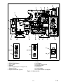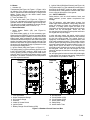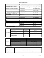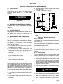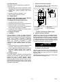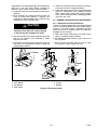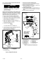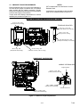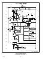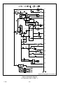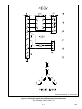
1
Diesel Generator Set
r
OPERATION AND SERVICE
for
69UG15
Generator Set Units
PID UG1450 and Higher
T--343 Rev --
OPERATION AND SERVICE MANUAL
DIESEL DRIVEN GENERATOR SET
MODEL
69UG15
TABLE OF CONTENTS
PARAGRAPH NUMBER
Page
SAFETY SUMMARY . . . . . . . . . . . . . . . . . . . . . . . . . . . . . . . . . . . . . . . . . . . . . . . . . . . . . . . . . . . . . . . . . . . .
Safety--i
GENERAL SAFETY NOTICES . . . . . . . . . . . . . . . . . . . . . . . . . . . . . . . . . . . . . . . . . . . . . . . . . . . . . . . . . . . . Safety--i
FIRST AID . . . . . . . . . . . . . . . . . . . . . . . . . . . . . . . . . . . . . . . . . . . . . . . . . . . . . . . . . . . . . . . . . . . . . . . . . . . . . Safety--i
OPERATING PRECAUTIONS . . . . . . . . . . . . . . . . . . . . . . . . . . . . . . . . . . . . . . . . . . . . . . . . . . . . . . . . . . . . Safety--i
MAINTENANCE PRECAUTIONS . . . . . . . . . . . . . . . . . . . . . . . . . . . . . . . . . . . . . . . . . . . . . . . . . . . . . . . . . . Safety--i
UNIT LABEL IDENTIFICATION . . . . . . . . . . . . . . . . . . . . . . . . . . . . . . . . . . . . . . . . . . . . . . . . . . . . . . . . . . . Safety--i
SPECIFIC WARNING AND CAUTION STATEMENTS . . . . . . . . . . . . . . . . . . . . . . . . . . . . . . . . . . . . . . . . Safety--i
DESCRIPTION . . . . . . . . . . . . . . . . . . . . . . . . . . . . . . . . . . . . . . . . . . . . . . . . . . . . . . . . . . . . . . . . . . . . . . . . . . . . . . .
1--1
1.1 INTRODUCTION . . . . . . . . . . . . . . . . . . . . . . . . . . . . . . . . . . . . . . . . . . . . . . . . . . . . . . . . . . . . . . . . . . . . .
1--1
1.2 CONFIGURATION IDENTIFICATION . . . . . . . . . . . . . . . . . . . . . . . . . . . . . . . . . . . . . . . . . . . . . . . . . . .
1--1
1.3 ENGINE . . . . . . . . . . . . . . . . . . . . . . . . . . . . . . . . . . . . . . . . . . . . . . . . . . . . . . . . . . . . . . . . . . . . . . . . . . . . .
1--5
1.3.1 Electronic Governor Module . . . . . . . . . . . . . . . . . . . . . . . . . . . . . . . . . . . . . . . . . . . . . . . . . . . . . . . .
1.3.2 Engine Air System . . . . . . . . . . . . . . . . . . . . . . . . . . . . . . . . . . . . . . . . . . . . . . . . . . . . . . . . . . . . . . . .
1--5
1--5
1.3.3 Lube Oil Filter Arrangement . . . . . . . . . . . . . . . . . . . . . . . . . . . . . . . . . . . . . . . . . . . . . . . . . . . . . . . .
1.3.4 Fuel System . . . . . . . . . . . . . . . . . . . . . . . . . . . . . . . . . . . . . . . . . . . . . . . . . . . . . . . . . . . . . . . . . . . . . .
1.4 ENGINE SCREW THREADS . . . . . . . . . . . . . . . . . . . . . . . . . . . . . . . . . . . . . . . . . . . . . . . . . . . . . . . . . . .
1.5 ALTERNATING CURRENT GENERATOR . . . . . . . . . . . . . . . . . . . . . . . . . . . . . . . . . . . . . . . . . . . . . . .
1.5.1 Principle of Operation . . . . . . . . . . . . . . . . . . . . . . . . . . . . . . . . . . . . . . . . . . . . . . . . . . . . . . . . . . . . . .
1.5.2 Alternating Current Generator Diagram . . . . . . . . . . . . . . . . . . . . . . . . . . . . . . . . . . . . . . . . . . . . . . .
1.6 BATTERY CHARGER . . . . . . . . . . . . . . . . . . . . . . . . . . . . . . . . . . . . . . . . . . . . . . . . . . . . . . . . . . . . . . . . .
1.7 OPERATING CONTROLS AND INSTRUMENTS . . . . . . . . . . . . . . . . . . . . . . . . . . . . . . . . . . . . . . . . .
1.7.1 Introduction . . . . . . . . . . . . . . . . . . . . . . . . . . . . . . . . . . . . . . . . . . . . . . . . . . . . . . . . . . . . . . . . . . . . . .
1.7.2 Control Panel and Related Components . . . . . . . . . . . . . . . . . . . . . . . . . . . . . . . . . . . . . . . . . . . . . .
1.8 SAFETY DEVICES . . . . . . . . . . . . . . . . . . . . . . . . . . . . . . . . . . . . . . . . . . . . . . . . . . . . . . . . . . . . . . . . . . .
1.9 UNIT SPECIFICATIONS . . . . . . . . . . . . . . . . . . . . . . . . . . . . . . . . . . . . . . . . . . . . . . . . . . . . . . . . . . . . . . .
1.10 ENGINE DATA . . . . . . . . . . . . . . . . . . . . . . . . . . . . . . . . . . . . . . . . . . . . . . . . . . . . . . . . . . . . . . . . . . . . . . .
OPERATION . . . . . . . . . . . . . . . . . . . . . . . . . . . . . . . . . . . . . . . . . . . . . . . . . . . . . . . . . . . . . . . . . . . . . . . . . . . . . . . . .
2.1 GENERATOR SET INSTALLATION . . . . . . . . . . . . . . . . . . . . . . . . . . . . . . . . . . . . . . . . . . . . . . . . . . . . .
2.2 GENERATOR SET REMOVAL . . . . . . . . . . . . . . . . . . . . . . . . . . . . . . . . . . . . . . . . . . . . . . . . . . . . . . . . .
2.3 STARTING AND STOPPING INSTRUCTIONS . . . . . . . . . . . . . . . . . . . . . . . . . . . . . . . . . . . . . . . . . . .
2.3.1 Pre-Start Inspection . . . . . . . . . . . . . . . . . . . . . . . . . . . . . . . . . . . . . . . . . . . . . . . . . . . . . . . . . . . . . . .
2.3.2 Starting Instructions . . . . . . . . . . . . . . . . . . . . . . . . . . . . . . . . . . . . . . . . . . . . . . . . . . . . . . . . . . . . . . .
2.3.3 Post-Start Inspection . . . . . . . . . . . . . . . . . . . . . . . . . . . . . . . . . . . . . . . . . . . . . . . . . . . . . . . . . . . . . .
2.3.4 Stopping Instructions . . . . . . . . . . . . . . . . . . . . . . . . . . . . . . . . . . . . . . . . . . . . . . . . . . . . . . . . . . . . . .
2.4 CONTROL CIRCUIT OPERATION . . . . . . . . . . . . . . . . . . . . . . . . . . . . . . . . . . . . . . . . . . . . . . . . . . . . . .
2.4.1 Sequence of Operation . . . . . . . . . . . . . . . . . . . . . . . . . . . . . . . . . . . . . . . . . . . . . . . . . . . . . . . . . . . .
TROUBLESHOOTING . . . . . . . . . . . . . . . . . . . . . . . . . . . . . . . . . . . . . . . . . . . . . . . . . . . . . . . . . . . . . . . . . . . . . . . . .
3.1 DIESEL ENGINE . . . . . . . . . . . . . . . . . . . . . . . . . . . . . . . . . . . . . . . . . . . . . . . . . . . . . . . . . . . . . . . . . . . . .
3.1.1 Engine Will Not Start . . . . . . . . . . . . . . . . . . . . . . . . . . . . . . . . . . . . . . . . . . . . . . . . . . . . . . . . . . . . . .
1--5
1--5
1--5
1--5
1--5
1--5
1--6
1--6
1--6
1--6
1--7
1--11
1--11
2--1
2--1
2--2
2--3
2--3
2--3
2--3
2--3
2--4
2--4
3--1
3--1
3--1
3.1.2
3.1.3
3.1.4
3.1.5
3.1.6
Engine Starts Then Stops . . . . . . . . . . . . . . . . . . . . . . . . . . . . . . . . . . . . . . . . . . . . . . . . . . . . . . . . . .
Engine Will Not Shut Off . . . . . . . . . . . . . . . . . . . . . . . . . . . . . . . . . . . . . . . . . . . . . . . . . . . . . . . . . . .
Starter Motor Malfunction . . . . . . . . . . . . . . . . . . . . . . . . . . . . . . . . . . . . . . . . . . . . . . . . . . . . . . . . . .
Malfunction In The Engine Starting Circuit . . . . . . . . . . . . . . . . . . . . . . . . . . . . . . . . . . . . . . . . . . . .
Miscellaneous Engine Troubleshooting . . . . . . . . . . . . . . . . . . . . . . . . . . . . . . . . . . . . . . . . . . . . . . .
i
3--1
3--2
3--2
3--2
3--3
T--343
TABLE OF CONTENTS - Continued
PARAGRAPH NUMBER
Page
3.2 BATTERY CHARGER (SOLID STATE) . . . . . . . . . . . . . . . . . . . . . . . . . . . . . . . . . . . . . . . . . . . . . . . . . .
3--3
3.3 ALTERNATING CURRENT GENERATOR . . . . . . . . . . . . . . . . . . . . . . . . . . . . . . . . . . . . . . . . . . . . . . .
3--4
3.4 AUTO RE-START OPTION . . . . . . . . . . . . . . . . . . . . . . . . . . . . . . . . . . . . . . . . . . . . . . . . . . . . . . . . . . . .
3--5
SERVICE AND PREVENTIVE MAINTENANCE . . . . . . . . . . . . . . . . . . . . . . . . . . . . . . . . . . . . . . . . . . . . . . . . . . .
4--1
4.1 INTRODUCTION . . . . . . . . . . . . . . . . . . . . . . . . . . . . . . . . . . . . . . . . . . . . . . . . . . . . . . . . . . . . . . . . . . . . .
4--1
4.2 PREVENTATIVE MAINTENANCE SCHEDULE . . . . . . . . . . . . . . . . . . . . . . . . . . . . . . . . . . . . . . . . . . .
4--1
4.3 BATTERY SERVICE . . . . . . . . . . . . . . . . . . . . . . . . . . . . . . . . . . . . . . . . . . . . . . . . . . . . . . . . . . . . . . . . . .
4--1
4.4 ENGINE SERVICE AND COMPONENTS . . . . . . . . . . . . . . . . . . . . . . . . . . . . . . . . . . . . . . . . . . . . . . . .
4--1
4.4.1 Bleeding the Fuel System . . . . . . . . . . . . . . . . . . . . . . . . . . . . . . . . . . . . . . . . . . . . . . . . . . . . . . . . . .
4--1
4.4.2 Servicing Fuel Pump Internal Filter . . . . . . . . . . . . . . . . . . . . . . . . . . . . . . . . . . . . . . . . . . . . . . . . . .
4--1
4.4.3 Fuel Filter . . . . . . . . . . . . . . . . . . . . . . . . . . . . . . . . . . . . . . . . . . . . . . . . . . . . . . . . . . . . . . . . . . . . . . . .
4--1
4.4.4 In--Line Fuel Filter . . . . . . . . . . . . . . . . . . . . . . . . . . . . . . . . . . . . . . . . . . . . . . . . . . . . . . . . . . . . . . . . .
4--1
4.4.5 Cooling System . . . . . . . . . . . . . . . . . . . . . . . . . . . . . . . . . . . . . . . . . . . . . . . . . . . . . . . . . . . . . . . . . . .
4--1
4.4.6 Servicing the Low Coolant Sensor . . . . . . . . . . . . . . . . . . . . . . . . . . . . . . . . . . . . . . . . . . . . . . . . . . .
4--4
4.4.7 Servicing Low Oil Pressure Switch . . . . . . . . . . . . . . . . . . . . . . . . . . . . . . . . . . . . . . . . . . . . . . . . . . .
4--4
4.4.8 Servicing Heater Switch . . . . . . . . . . . . . . . . . . . . . . . . . . . . . . . . . . . . . . . . . . . . . . . . . . . . . . . . . . . .
4--4
4.4.9 Servicing Poly V-belt . . . . . . . . . . . . . . . . . . . . . . . . . . . . . . . . . . . . . . . . . . . . . . . . . . . . . . . . . . . . . .
4--4
4.4.10 Lube Oil Filter . . . . . . . . . . . . . . . . . . . . . . . . . . . . . . . . . . . . . . . . . . . . . . . . . . . . . . . . . . . . . . . . . . . .
4--5
4.4.11 Engine Speed . . . . . . . . . . . . . . . . . . . . . . . . . . . . . . . . . . . . . . . . . . . . . . . . . . . . . . . . . . . . . . . . . . . .
4--5
4.4.12 Replacing the Engine Speed Sensor . . . . . . . . . . . . . . . . . . . . . . . . . . . . . . . . . . . . . . . . . . . . . . . . .
4--5
4.4.13 Engine Air Cleaner . . . . . . . . . . . . . . . . . . . . . . . . . . . . . . . . . . . . . . . . . . . . . . . . . . . . . . . . . . . . . . . .
4--5
4.4.14 Engine Crankcase Breather . . . . . . . . . . . . . . . . . . . . . . . . . . . . . . . . . . . . . . . . . . . . . . . . . . . . . . . .
4--6
4.4.15 Servicing Intake Heater . . . . . . . . . . . . . . . . . . . . . . . . . . . . . . . . . . . . . . . . . . . . . . . . . . . . . . . . . . . .
4--6
4.5 SERVICING THE ALTERNATING CURRENT GENERATOR . . . . . . . . . . . . . . . . . . . . . . . . . . . . . . .
4--6
4.5.1 Preventative Maintenance and Operating Precautions . . . . . . . . . . . . . . . . . . . . . . . . . . . . . . . . . .
4--6
4.5.2 Generator Repair/Test Procedures . . . . . . . . . . . . . . . . . . . . . . . . . . . . . . . . . . . . . . . . . . . . . . . . . . .
4--7
4.5.3 Bearing Replacement . . . . . . . . . . . . . . . . . . . . . . . . . . . . . . . . . . . . . . . . . . . . . . . . . . . . . . . . . . . . . .
4--8
4.5.4 Generator Removal and Installation . . . . . . . . . . . . . . . . . . . . . . . . . . . . . . . . . . . . . . . . . . . . . . . . . .
4--8
4.6 GENERAL GENERATOR SET MAINTENANCE . . . . . . . . . . . . . . . . . . . . . . . . . . . . . . . . . . . . . . . . . .
4--9
4.6.1 Maintenance Of Painted Surfaces . . . . . . . . . . . . . . . . . . . . . . . . . . . . . . . . . . . . . . . . . . . . . . . . . . .
4--9
4.6.2 Check and Replace Isolators/Shockmounts . . . . . . . . . . . . . . . . . . . . . . . . . . . . . . . . . . . . . . . . . . . 4--10
4.7 UNIDRIVE TORQUE REQUIREMENTS . . . . . . . . . . . . . . . . . . . . . . . . . . . . . . . . . . . . . . . . . . . . . . . . . 4--11
SCHEMATICS . . . . . . . . . . . . . . . . . . . . . . . . . . . . . . . . . . . . . . . . . . . . . . . . . . . . . . . . . . . . . . . . . . . . . . . . . . . . . . . .
5--1
5.1 INTRODUCTION . . . . . . . . . . . . . . . . . . . . . . . . . . . . . . . . . . . . . . . . . . . . . . . . . . . . . . . . . . . . . . . . . . . . .
5--1
T--343
ii
LIST OF ILLUSTRATIONS
FIGURE NUMBER
Figure 1-1 Generator Set . . . . . . . . . . . . . . . . . . . . . . . . . . . . . . . . . . . . . . . . . . . . . . . . . . . . . . . . . . . . . . . . . . . . . .
Figure 1-2 Generator Set -- Top View . . . . . . . . . . . . . . . . . . . . . . . . . . . . . . . . . . . . . . . . . . . . . . . . . . . . . . . . . . . .
Figure 1-3 Fuel System Diagram . . . . . . . . . . . . . . . . . . . . . . . . . . . . . . . . . . . . . . . . . . . . . . . . . . . . . . . . . . . . . . .
Figure 1-4 Lube Oil . . . . . . . . . . . . . . . . . . . . . . . . . . . . . . . . . . . . . . . . . . . . . . . . . . . . . . . . . . . . . . . . . . . . . . . . . . .
Figure 1-5 A--C Generator Circuit Diagram . . . . . . . . . . . . . . . . . . . . . . . . . . . . . . . . . . . . . . . . . . . . . . . . . . . . . . .
Figure 1-6 Standard Control Panel and Box . . . . . . . . . . . . . . . . . . . . . . . . . . . . . . . . . . . . . . . . . . . . . . . . . . . . . .
Figure 1-7 Customer Specific Control Panel and Box . . . . . . . . . . . . . . . . . . . . . . . . . . . . . . . . . . . . . . . . . . . . . .
Figure 1-8 Auto Restart Control Box and Panel . . . . . . . . . . . . . . . . . . . . . . . . . . . . . . . . . . . . . . . . . . . . . . . . . . .
Figure 2-1 Typical Generator Set Mounting - Standard Mount . . . . . . . . . . . . . . . . . . . . . . . . . . . . . . . . . . . . . .
Figure 2-2 Typical Generator Set Mounting - Quick Mount . . . . . . . . . . . . . . . . . . . . . . . . . . . . . . . . . . . . . . . . .
Figure 4-1 Mechanical Fuel Pump . . . . . . . . . . . . . . . . . . . . . . . . . . . . . . . . . . . . . . . . . . . . . . . . . . . . . . . . . . . . . .
Figure 4-2 Low Coolant Sensor . . . . . . . . . . . . . . . . . . . . . . . . . . . . . . . . . . . . . . . . . . . . . . . . . . . . . . . . . . . . . . . . .
Figure 4-3 Air Filter (Dry Element Type) . . . . . . . . . . . . . . . . . . . . . . . . . . . . . . . . . . . . . . . . . . . . . . . . . . . . . . . . .
Figure 4-4 Air Filter (Oil Bath Type) . . . . . . . . . . . . . . . . . . . . . . . . . . . . . . . . . . . . . . . . . . . . . . . . . . . . . . . . . . . . .
Figure 4-5 Engine Crankcase Breather . . . . . . . . . . . . . . . . . . . . . . . . . . . . . . . . . . . . . . . . . . . . . . . . . . . . . . . . . .
Figure 4-6 Rectifier Removal . . . . . . . . . . . . . . . . . . . . . . . . . . . . . . . . . . . . . . . . . . . . . . . . . . . . . . . . . . . . . . . . . . .
Figure 4-7 A-C Generator Rectifier Assembly . . . . . . . . . . . . . . . . . . . . . . . . . . . . . . . . . . . . . . . . . . . . . . . . . . . .
Figure 4-8 Truss and Isolator . . . . . . . . . . . . . . . . . . . . . . . . . . . . . . . . . . . . . . . . . . . . . . . . . . . . . . . . . . . . . . . . . . .
Figure 4-9 Engine Shockmounts . . . . . . . . . . . . . . . . . . . . . . . . . . . . . . . . . . . . . . . . . . . . . . . . . . . . . . . . . . . . . . . .
Figure 4-10 Generator Shockmounts . . . . . . . . . . . . . . . . . . . . . . . . . . . . . . . . . . . . . . . . . . . . . . . . . . . . . . . . . . . .
Figure 4-11 Unidrive Torque Requirements . . . . . . . . . . . . . . . . . . . . . . . . . . . . . . . . . . . . . . . . . . . . . . . . . . . . . . .
Figure 5-1 Schematic Diagram - Legend . . . . . . . . . . . . . . . . . . . . . . . . . . . . . . . . . . . . . . . . . . . . . . . . . . . . . . . . .
Figure 5-2 Schematic Diagram . . . . . . . . . . . . . . . . . . . . . . . . . . . . . . . . . . . . . . . . . . . . . . . . . . . . . . . . . . . . . . . . .
Figure 5-3 Schematic Diagram 460 Volt Alternating Current Generator . . . . . . . . . . . . . . . . . . . . . . . . . . . . . . .
Figure 5-4 Schematic Diagram 230 Volt Alternating Current Generator . . . . . . . . . . . . . . . . . . . . . . . . . . . . . .
Figure 5-5 Schematic Diagram - Legend . . . . . . . . . . . . . . . . . . . . . . . . . . . . . . . . . . . . . . . . . . . . . . . . . . . . . . . . .
Figure 5-6 Schematic Diagram . . . . . . . . . . . . . . . . . . . . . . . . . . . . . . . . . . . . . . . . . . . . . . . . . . . . . . . . . . . . . . . . .
Figure 5-7 Schematic Diagram 460 Volt Alternating Current Generator . . . . . . . . . . . . . . . . . . . . . . . . . . . . . . .
Page
1--3
1--4
1--5
1--5
1--6
1--7
1--8
1--8
2--1
2--2
4--1
4--4
4--5
4--6
4--6
4--8
4--8
4--9
4--10
4--10
4--11
5--1
5--2
5--3
5--4
5--5
5--6
5--7
LIST OF TABLES
TABLE NUMBER
Page
Table 1-1 Model Chart . . . . . . . . . . . . . . . . . . . . . . . . . . . . . . . . . . . . . . . . . . . . . . . . . . . . . . . . . . . . . . . . . . . . . . . . .
1--2
Table 1-2 Auto Restart Preset Values . . . . . . . . . . . . . . . . . . . . . . . . . . . . . . . . . . . . . . . . . . . . . . . . . . . . . . . . . . . .
1--9
Table 1-3 Auto Restart Sequencing . . . . . . . . . . . . . . . . . . . . . . . . . . . . . . . . . . . . . . . . . . . . . . . . . . . . . . . . . . . . . .
1--9
Table 1-4 Safety Devices . . . . . . . . . . . . . . . . . . . . . . . . . . . . . . . . . . . . . . . . . . . . . . . . . . . . . . . . . . . . . . . . . . . . . . . 1--11
Table 4-1 Preventative Maintenance Actions and Schedule . . . . . . . . . . . . . . . . . . . . . . . . . . . . . . . . . . . . . . . . . .
4--2
iii
T--343
SAFETY SUMMARY
GENERAL SAFETY NOTICES
The following general safety notices supplement the specific warnings and cautions appearing elsewhere in this
manual. They are recommended precautions that must be understood and applied during operation and maintenance
of the equipment covered herein. The general safety notices are presented in the following three sections labeled:
First Aid, Operating Precautions and Maintenance Precautions. A listing of the specific warnings and cautions
appearing elsewhere in the manual follows the general safety notices.
FIRST AID
An injury, no matter how slight, should never go unattended. Always obtain first aid or medical attention immediately.
OPERATING PRECAUTIONS
Always wear safety glasses and hearing protection.
Keep hands, clothing and tools clear of the radiator fan and rotating belts.
No work should be performed on the unit until all circuit breakers and start-stop switches are turned off and the
negative battery terminal has been disconnected..
Always work in pairs. Never work on the equipment alone.
In case of severe vibration or unusual noise, stop the unit and investigate.
MAINTENANCE PRECAUTIONS
Be sure power is turned off and the negative battery cable is disconnected before working on generator set.
Do not bypass any electrical safety devices, e.g. bridging an overload, or using any sort of jumper wires. Problems with
the system should be diagnosed, and any necessary repairs performed, by qualified service personnel.
In case of electrical fire, open circuit switch and extinguish with CO2 (never use water).
Fuel Tanks present explosion, fire and rupture hazards even if liquid fuel has been drained. Do not attempt any repairs,
especially repairs using flame, welder or torch, unless you have been properly trained and the tank has been emptied
of liquid fuel and fuel vapors and the tank is properly ventilated.
UNIT HAZARD LABEL IDENTIFICATION
To help identify the hazard labels on the Unit and explain the level of awareness each one carries, explanations with
appropriate consequences are provided below:
DANGER
Indicates an immediate hazard which WILL result in severe personal injury or death.
WARNING
Indicates hazards or unsafe conditions which COULD result in severe personal injury or death.
CAUTION
Indicates potential hazards or unsafe practices which COULD result in minor personal injury, product or property
damage.
Safety--i
T-343
SPECIFIC WARNING AND CAUTION STATEMENTS
The statements that follow are applicable to the generator set and appear elsewhere in this manual. These recommended precautions must be understood and applied during operation and maintenance of the equipment covered
herein.
WARNING
CAUTION
Never pour cold water into a hot engine.
Beware of moving poly V-belt, belt driven
components and hot exhaust components.
CAUTION
WARNING
Use only ethylene glycol, anti-freeze (with
inhibitors) in system. Use of glycol by itself
will damage the cooling system.
Under no circumstances should ether or
any other unauthorized starting aids be
used in conjunction with the air intake heater.
CAUTION
WARNING
Never open the radiator cap when the coolant is hot.
Beware of moving poly V-Belt and belt driven components.
WARNING
CAUTION
Beware of pinch points.
Always cover the engine inlet tube while the
air cleaner is being serviced.
WARNING
Do not use gasoline to clean air cleaner
parts.
CAUTION
Do not underfill or overfill the oil bath cups.
Overfilling of cups causes loss of capacity;
underfilling cups causes lack of filtering efficiency.
WARNING
Do not direct water or steam into the generator openings. Do not allow any soap and
water solutions to enter the alternator.
CAUTION
WARNING
When trying to restore residual magnetism,
be sure to wear safety glasses and non-conductive gloves. Use an insulated 12 gauge
(or higher) jumper wire. Cut off all but a few
strands from both ends of the jumper wire
to help prevent fusing.
High voltage (dielectric) testing must not be
performed to the machine without first observing NEMA rules. The insulation of this
generator winding may be safely checked
by using a megger. A high megger reading
indicates good insulation.
CAUTION
CAUTION
The rotor should not be pulled out from the
alternator more than 0.75 inches. Damage
to the bearing and windings may result.
Observe proper polarity when installing the
battery or connecting a battery charger, the
negative battery terminal must be
grounded. Reverse polarity may damage
the charging system. When charging the
battery in unit, isolate the battery by disconnecting the negative battery terminal first,
then the positive. Once the battery has been
charged, connect the positive battery terminal first, then the negative.
T-343
CAUTION
Continued
operation
with
failed
shockmounts may result in engine or generator damage.
Safety--ii
SECTION 1
DESCRIPTION
The 69UG15 is available as a standard configuration,
with an Auto Restart option or with Auto Restart and Low
Coolant Sensor. The Auto Restart option automatically
restarts the unit in the event of a unit shutdown. Auto
Restart also offers built--in indicators that signal low oil
pressure, high water temperature, overspeed, and
other overcrank conditions.
1.1 INTRODUCTION
The Carrier Transicold model 69UG15 under--mounted
diesel--driven generator sets provide electrical power
for all--electric refrigeration units.
The generator set (see Figure 1-1 and Figure 1-2)
consists of a diesel engine direct--connected to an
alternating current generator and mounted in a
structural steel frame. The engine is a vertical in--line,
four cylinder diesel manufactured by Kubota, while the
generator is a 15 kW, brushless, single bearing type
manufactured by Lima. The generator provides a
constant 460 or 230 VAC, three--phase, 60 hertz
electrical supply.
Electrical controls are mounted in a control box with
operating controls and gauges mounted on a control
panel, which also serves as the control box cover. The
control panel components are protected by a deflector
assembly or a windowed control box door.
Auxiliary engine equipment consists of the battery, solid
state battery charging system, “spin--on” lube oil filter,
fuel filter and other necessary components for proper
unit operation. The water pump and the radiator cooling
fan are belt--driven from the engine crankshaft. All
references to engine are as viewed from the fly wheel
end.
1.2 CONFIGURATION IDENTIFICATION
Generator set identification information is provided on a
label located below the left mounting pad to the left of the
access service door (front facing). The label provides
the generator set model number, serial number, and
parts identification number (PID). The model number
identifies the overall configuration, while the PID
provides information on specific optional equipment.
Separately bound manuals covering the diesel engine
are also available (see the following chart).
Manual/
Form No.
62---11335
62---11362
1--1
Equipment
Covered
V2203--DI
V2203--DI
Type of
Manual
Engine Parts List
Workshop
T-343
Table 1-1 Model Chart
LEGEND
A1
A2
B1
B2
B3
------
Standard Mount -- (See Figure 2-1)
B4
Quick Mount -- (See Figure 2-2)
C1
Receptacle Box -- with Circuit Breaker
C2
Receptacle Box -- with Circuit Breaker
C3
Receptacle Box -- Customer Specific
Electrical Wiring
Schematic and
PID
Model
Diagram Figures
UG1450
5-1, 5-2, 5-3, 5-4
UG1451
5-1, 5-2, 5-3, 5-4
69UG15--050S--05
UG1452
5-1, 5-2, 5-3, 5-4
UG1453
5-1, 5-2, 5-3, 5-4
UG1455
5-1, 5-2, 5-3, 5-4
69UG15--050S--06
UG1456
5-1, 5-2, 5-3, 5-4
69UG15--050S--07
UG1457
5-5, 5-6, 5-7
69UG15--050S--08
UG1458
5-1, 5-2, 5-3, 5-4
UG1459
5-1, 5-2, 5-3, 5-4
69UG15--050Q--06
UG1460
5-1, 5-2, 5-3, 5-4
UG1461
5-1, 5-2, 5-3, 5-4
UG1462
5-1, 5-2, 5-3, 5-4
69UG15--068S--05
UG1463
5-1, 5-2, 5-3, 5-4
69UG15--068Q--05
UG1464
5-1, 5-2, 5-3, 5-4
69UG15--080S--05
UG1465
5-1, 5-2, 5-3, 5-4
UG1466
5-1, 5-2, 5-3, 5-4
69UG15--080Q--05
UG1467
5-1, 5-2, 5-3, 5-4
T-343
1--2
-----
Receptacle Box -- Interlock
460 Volt -- Standard
460 Volt -- with Auto--Restart
460 Volt -- Customer Specific
Unit
Mounting
Receptacle
Box
Control Box
A1
A1
A1
A1
A1
A1
A1
A1
A2
A2
A1
A1
A1
A2
A1
A2
A2
B1
B1
B1
B1
B2
B2
B4
B3
B2
B2
B1
B1
B1
B1
B1
B1
B1
C1
C1
C1
C1
C1
C1
C2
C3
C1
C1
C1
C1
C1
C1
C1
C1
C1
5
1
3
2
4
16
15
14
13
12
11
15
10
9
8
7
6
15
15
230 VOLT
460 VOLT
14
1.
2.
3.
4.
5.
6.
7.
8.
14
14
Mechanical Fuel Pump
Injector Pump
Engine Speed Sensor
Poly V--Belt
Radiator
Controls (See Figure 1-6 or Figure 1-8)
Engine Oil Filter
Engine Shockmount (Typical)
9.
10.
11.
12.
13.
14.
15.
16.
Lube Oil Dipstick/Fill Cap
Starter
Air Cleaner
Generator Shockmount
Receptacle Box
Receptacle
Circuit Breaker
Air Filter Indicator (if equipped)
Figure 1-1 Generator Set
1--3
T-343
1
2
3
11
4
10
5
6
9
7
8
1.
2.
3.
4.
5.
6.
Fuel Tank
Exhaust Muffler
Solid State Battery Charger
Low Coolant Sensor (If Equipped)
Water Temperature Sensor
Water Temperature Switch
7.
8.
9.
10.
11.
Engine
Coolant Overflow Bottle
Alternating Current Generator
AC Generator Connection Box Access
Battery
Figure 1-2 Generator Set -- Top View (Top Frame Members Removed for Clarity)
T-343
1--4
1.3 ENGINE
3
4
1.
2.
3.
4.
1.5 ALTERNATING CURRENT GENERATOR
1.5.1 Principle of Operation
The Marathon Alternator Company (Lima) brushless
AC generator (see Figure 1-2, item 9) is a
self--regulated, rotating field synchronous unit. The
generator stator and exciter stator are combined in a
common housing. The generator field, exciter rotor, and
rotating rectifier assembly are mounted on a common
shaft. The output of the exciter rotor is applied to the
generator field winding through a rotating, full--wave
bridge, silicon rectifier unit.
All connections between the exciter stator windings and
the generator stator windings are internal within the
stator housing. Only the output power leads are
connected at the terminal box, which is located on top of
the generator.
1.5.2 Alternating Current Generator Diagram
Figure 1-5 shows the internal schematic diagram of the
generator, exciter, and rectifier unit. The generator is a
three--phase unit, and the exciter stator and exciter rotor
also have three--phase windings. A portion of the exciter
stator windings is connected across a tap on the
generator stator winding. This exciter shunt winding
provides the generator field excitation power required
for the generator no--load voltage. Another portion of the
exciter stator windings is connected in series with the
output of the generator and provides a compounding
excitation characteristic.
All threads used on the engine are metric.
8
9
6
2
4
7
3
1
1.
2.
3.
4.
Fuel Tank
Fuel Supply Line
Inline Fuel Filter
Mechanical
Fuel Pump (Engine)
Oil Filter (Primary)
Oil Pressure Sender
Oil Pressure Switch
Oil Pan
Figure 1-4 Lube Oil
1.4 ENGINE SCREW THREADS
5
2
1
The engine is a vertical, in--line four cylinder diesel
engine, which is direct--connected to the alternating
current generator. Information on the major engine
systems is provided in the following subparagraphs.
1.3.1 Electronic Governor Module
The electronic governor module is a solid state control
module preprogrammed for 1800 RPM. The electronic
governor module, along with the engine speed sensor,
replaced the manual governor in order to provide a
constant engine speed.
1.3.2 Engine Air System
The air cleaner (Item 11, Figure 1-1) is designed to
prolong engine life and performance by preventing dirt
and grit from entering the engine and causing excessive
wear on all operating parts. In order for the air filter to
operate properly, the operator must regularly maintain
the air cleaner equipment in accordance with the
instructions provided within this document.
1.3.3 Lube Oil Filter Arrangement
The engine lubricating oil filter is mounted in a horizontal
arrangement and shown in Figure 1-4.
1.3.4 Fuel System
The fuel system is fitted with an in--line pre--filter and a
fuel filter, which also acts as a water separator. The filter
is also fitted with a heater. The fuel system is shown in
Figure 1-3.
5. Fuel Filter and Water
Separator
6. Injection Pump
8. Fuel Bleed Valve
7. Injector Nozzles
9. Fuel Return Line
Figure 1-3 Fuel System Diagram
1--5
T-343
The rotor is, in effect, the secondary of a rotating current
transformer induction frequency converter. The exciter
rotor output voltage is applied to the generator field
windings by a three--phase, full wave rotating silicon
rectifier unit. The response time of the excitation system
is very fast as the exciter stator carries an alternating
current corresponding to the load current that appears
immediately on the exciter primary. An increase in load
current will cause an immediate increase in the exciter
secondary output voltage, which is rectified and applied
to the generator field windings. The inherent
compounding characteristics of the excitation system
provide excellent voltage regulation even under heavy
overload conditions.
1.6 BATTERY CHARGER
The solid state battery charger (see Figure 1-2) is
located to the left of the radiator. The charger is powered
by the generator, and this input is protected by a circuit
breaker located on the control panel. The battery
charger produces a tapered charge (25 amps
maximum) and is designed not to overcharge the
battery.
1.7 OPERATING CONTROLS AND
INSTRUMENTS
1.7.1 Introduction
Components required for monitoring and controlling the
unit are located in the control box, on the control panel
(see Figure 1-6) and on the receptacle box (see
Figure 1-1).
1.7.2 Control Panel and Related Components
a. Gauges and Senders
1. Oil Pressure Gauge (see Figure 1-6, Figure 1-7,
Figure 1-8)
The purpose of this gauge is to observe normal
operating engine oil pressure. Normal oil pressure is 35
to 60 psig (3.3 to 5.2 kg/cm2).
2. Oil Pressure Sender (see Figure 1-4)
This device senses engine lube oil pressure and
transmits a signal to the oil pressure gauge. The oil
pressure sender is located on the oil filter housing.
3. Water Temperature Gauge (see Figure 1-6,
Figure 1-7, Figure 1-8)
The function of this gauge is to observe water operating
temperature. The gauge is connected to the water
temperature sender.
4. Water Temperature Sender (see Figure 1-2)
This device senses engine water temperature and
transmits a signal to the water temperature gauge.
5. Low Coolant Sensor (see Figure 1-2)
This device senses the coolant level inside the radiator
and will complete a conductive circuit as long as the
probes remain immersed in coolant. When the coolant
level falls below the probes, a signal will be sent to the
auto restart module, shutting down the engine and all
12--volt circuitry.
6. Auto Restart Module
Auto start/restart is provided to simplify the start--up
process and provide an automatic restart feature that
will automatically attempt to restart the unit in the event
of shutdown. Four LEDs are used to indicate shutdown
from overcrank, overspeed, low oil pressure, and high
water temperature. A fifth LED is used to indicate the
unit is running. Refer to Table 1-2 for system preset
values.
The auto restart function will perform a series of six
attempts to restart the unit and make three attempts
within each series. Once the function has completed all
18 attempts, the unit will automatically lock out future
crank attempts. Refer to Table 1-3 for detailed
information on auto restart sequencing.
FIELD
SHUNT
SERIES
STATOR
GENERATOR
STATOR
L
O
A
D
ROTOR
RECTIFIER
ASSEMBLY
EXCITER
Figure 1-5 A--C Generator Circuit Diagram
CAUTION
Observe proper polarity when installing the
battery or connecting a battery charger. The
negative battery terminal must be
grounded. Reverse polarity may damage
the charging system. When charging the
battery in unit, isolate the battery by
disconnecting the negative battery terminal
first, then the positive. Once the battery has
been charged, connect the positive battery
terminal first, then the negative.
T-343
1--6
3. Ignition Switch (IGN)(Auto Restart) (see Figure 1-8)
The ignition switch is of the maintained contact type to
be used in the RUN/OFF positions. When switched to
the RUN position, it energizes the control module, which
in turn controls all functions of the genset.
1.8 SAFETY DEVICES
Safety devices, such as circuit breakers, fuses, and
safety switches, protect system components from
damage.
The AC generator, solid state battery charger, fuel
heater, high water temperature, safety relay, total time
meter and intake air heater are protected by circuit
breakers. If a safety device opens and there is an
interruption of electrical current, the electronic governor
module will be de--energized, which will also
de--energize the fuel solenoid, interrupt the fuel flow to
the engine and stop the engine.
In units with auto restart, the engine, engine control
devices, and engine monitoring devices are protected
by the auto restart module, low coolant sensor (if
equipped), circuit breaker, low oil pressure switch, and
high water temperature switch. These safety devices
monitor system operating conditions and open a set of
electrical contacts when an unsafe condition occurs. If a
safety device opens and there is an interruption of
electrical current, the electronic governor module will be
de--energized, which will also de--energize the fuel
solenoid, interrupt the fuel flow to the engine and stop
the engine.
De--energizing the fuel solenoid shuts off the fuel supply
to the engine; thus stopping the engine. Safety device
specifications are provided in Table 1-4.
b. Meters
1. Ammeter (A)
The ammeter (see Figure 1-6, Figure 1-7, Figure 1-8) is
an indicator of the charging system and unit electrical
draw. It indicates the rate of discharge or charge of the
battery. During start up, the intake heater draws
approximately 42 amps.
2. Total Time Meter (TT)
The total time meter (see Figure 1-6, Figure 1-7,
Figure 1-8) calculates the total hours and provides an
accurate readout of accumulated engine running time.
This data can be used to establish the proper periodic
maintenance schedule (refer to Section 4.1).
c. Manual Switches
1. Intake Heater Switch (HS) (see Figure 1-6,
Figure 1-7)
The intake heater switch is of the momentary type.
When held in the PREHEAT position, the switch allows
approximately 42 amps of battery current to flow into the
intake heater, which preheats the air within the intake
manifold and allows the engine to start. After starting the
engine, the intake heater switch should continue to be
held in the ON position for approximately 5 seconds until
the engine has developed enough oil pressure to close
the oil pressure safety switch.
2. Ignition Switch (IGN) (see Figure 1-6, Figure 1-7)
The ignition switch is of the momentary type to be used
in the OFF/ON/START positions. When held in the
START (ignition) position, it energizes the starter motor
solenoid, which in turn allows the starter motor to crank
the engine. The switch is released to the RUN position
once the engine has started.
CONTROL
PANEL
CONTROL
BOX
12
13
3
2
11
4
1
5
10
6
9
7
8
1.
2.
3.
4.
5.
6.
7.
Total Time Meter
Water Temperature Gauge
Oil Pressure Gauge
Ammeter
Intake Air Heater Switch
Ignition Switch
Battery Charger Circuit Breaker (CB5)
8.
9.
10.
11.
12.
13.
Ground Studs
Circuit Breaker (CB2)
Circuit Breaker (CB3)
Intake Heater Relay
Safety Relay
Intake Heater Timer
Figure 1-6 Standard Control Panel and Box
1--7
T-343
CONTROL
PANEL
CONTROL
BOX
3
2
11
10
1
4
5
12
9
6
7
8
13
1.
2.
3.
4.
5.
6.
7.
8.
9.
10.
11.
12.
13.
Total Time Meter
Water Temperature Gauge
Oil Pressure Gauge
Ammeter
Intake Air Heater Switch
Ignition Switch
Battery Charger Fuse
or Circuit Breaker (CB5)
Ground Studs
Safety Relay
Intake Heater Relay
Intake Heater Timer
Circuit Breaker (CB2)
Circuit Breaker (CB3)
Figure 1-7 Customer Specific Control Panel and Box
CONTROL
PANEL
3
4
CONTROL
BOX
5
13
14
2
1
6
12
7
11
8
10
9
9. Battery Charger Fuse
Total Time Meter
or Circuit Breaker (CB5)
Engine Start Alarm (Buzzer)
10. Ground Studs
Water Temperature Gauge
11. Circuit Breaker (CB2)
Auto Restart Module
12. Starter Relay (SR)
Oil Pressure Gauge
13. Low Coolant Relay (LR)
Ammeter
14. Intake Heater Relay (HR)
Engine Start/Intake Heater
15. Safety Relay (S)
Energized Light
16. Circuit Breaker (CB3)
8. Ignition Switch
Figure 1-8 Auto Restart Control Box and Panel
1.
2.
3.
4.
5.
6.
7.
T-343
1--8
15
16
Table 1-2 Auto Restart Preset Values
Indicator
Preset Value
Description
Overspeed
2100 RPM
Overspeed is the point at which the unit will signal for shutdown
Crank Disconnect
700 RPM
Crank Disconnect is the point at which the auto restart module
senses the engine has started and will disengage the starter
Shutdown Lockout
Delay
15 seconds
The oil pressure and water temperature inputs are ignored during
this 15 second delay (after start up)
Intake Heater Delay
30 seconds
preheat
3 minutes
postheat
The delay is used during start up. The intake heater delay begins
timing after the auto restart module signal is received. During the
entire delay, the intake heater circuit will be energized, an indicator
light will be illuminated, and an alarm will sound. When the delay
expires, the unit will crank.
Crank Attempts
18 attempts
A series of six attempts with three attempts in each series
(total of 18 attempts)
Table 1-3 Auto Restart Sequencing
*Engine crank and rest is repeated three times each series unless the engine starts.
Series
Attempt
Number
1
2
3
Intake
Heater
Energized
in
Seconds
30
30
30
Fuel
Solenoid
Engaged
X
X
X
Engine
Engine
Crank
Rest
Duration
Duration
(Seconds) (Seconds)
Up To 15
Up To 15
Up To 15
Engine Status
25
If the engine starts:
a. Run sequence begins
b. Intake heater remains energized for 3
minutes
If the engine fails to start:
a. Intake heater will de--energize.
b. Fuel solenoid will de--energize.
c. Crank output will de--energize.
d. Overcrank LED will flash once. Wait two
seconds and repeat.
e. Unit will rest 30 minutes and proceed to
the next series.
25
If the engine starts:
a. Run sequence begins.
b. Intake heater remains energized for 3
minutes.
If the engine fails to start:
a. Intake heater will de--energize.
b. Fuel solenoid will de--energize.
c. Crank output will de--energize.
d. Overcrank LED will flash twice. Wait two
seconds and repeat.
e. Unit will rest 30 minutes and proceed to
the next series.
25
If the engine starts:
a. Run sequence begins.
If the engine fails to start:
a. Intake heater will de--energize.
b. Fuel solenoid will de--energize.
c. Crank output will de--energize.
d. Overcrank LED will flash three times.
Wait two seconds and repeat.
e. Unit will rest five hours and proceed to
the next series.
1--9
T-343
Table 1-3 Auto Restart Sequencing (Continued)
Series
Attempt
Number
4
5
6
T-343
Intake
Heater
Energized
in
Seconds
30
30
30
Fuel
Solenoid
Engaged
X
X
X
Engine
Engine
Crank
Rest
Duration
Duration
(Seconds) (Seconds)
Up To 15
Up To 15
Up To 15
Engine Status
25
If the engine starts:
a. Run sequence begins.
If the engine fails to start:
a. Intake heater will de--energize.
b. Fuel solenoid will de--energize.
c. Crank output will de--energize.
d. Overcrank LED will flash four times. Wait
two seconds and repeat.
e. Unit will rest five hours and proceed to
the next series.
25
If the engine starts:
a. Run sequence begins.
If the engine fails to start:
a. Intake heater will de--energize.
b. Fuel solenoid will de--energize.
c. Crank output will de--energize.
d. Overcrank LED will flash five times. Wait
two seconds and repeat.
e. Unit will rest five hours and proceed to
the next series.
25
If the engine starts:
a. Run sequence begins.
If the engine fails to start:
a. Intake heater will de--energize.
b. Fuel solenoid will de--energize.
c. Crank output will de--energize.
d. Overcrank LED will illuminate solid and
lock out future crank attempts.
e. To reset, turn unit power switch OFF and
back ON.
1--10
Table 1-4 Safety Devices
Unsafe Condition
Low engine lubricating oil pressure
High engine cooling water temperature
Low coolant
Excessive current draw by the safety relay, fuel heater, water temperature gauge,
oil pressure gauge or total time meter
Excessive current draw by the electronic
governor module
Safety Switch
ENGINE
Low oil pressure switch (LOP) -Automatic reset
Water temperature switch (HWT) -Automatic reset
Low coolant sensor
Automatic reset
Switch Setting
Opens below 18 psig
(1.27 kg/cm2)
Opens at 230F (110C)
Opens with a loss of 32
ounces of coolant
Circuit breaker (CB--2) -Automatic reset
Trips at 30 amps
Fuse 1, 2, 3
Trips at 10 amps
Excessive current draw on intake heater
circuit
INTAKE HEATER
Circuit breaker (CB--3) -Automatic reset
BATTERY CHARGER
Opens at 50 amps
Excessive current draw on 230 volt feed
circuit
Circuit breaker (CB--5) -- Manual reset
Opens at 3 amps
GENERATOR
Circuit breaker (CB--1, 460 volt) -Manual reset
Circuit breaker (CB--4, 230 volt) -Manual reset
Trips at 26 amps
(460 VAC)
Trips at 48 amps
(230 VAC)
Excessive current draw by load
1.9 UNIT SPECIFICATIONS
Nominal Tank Sizes
Fill Capacity
52 gallons
(256 liters)
52 gallons
(256 liters)
67.5 gallons
(197 liters)
85 gallons
(322 liters)
50 Gallon Steel
a. Fuel Tanks
50 Gallon Aluminum
65 Gallon Steel
80 Gallon Aluminum
Draw Capacity
50 gallons*
(246 liters)
50 gallons*
(246 liters)
65 gallons*
(189 liters)
80 gallons*
(303 liters)
*Allows for DOT required 5% vapor space
b. Weights
Battery
Generator (A--C)
Engine (Dry) -- without Accessories
Unit (with 50 gal steel tank, dry)
Unit (with 50 gal aluminum tank, dry)
Unit (with 65 gal steel tank, dry)
Unit (with 80 gal aluminum tank, dry)
63 lb (28.6 kg)
280 lb (127 kg)
434 lb (197 kg) Approximate
1555 lb (705.3 kg)
1485 lb (673.6 kg)
1580 lb (716.7 kg)
1545 lb (700.8 kg)
1.10 ENGINE DATA
a. Bore/Stroke
b. Compression Ratio
c. Cylinders (Number)
d. Displacement
e. Firing Order
3.26 in. (38 mm) / 4.03 in. (102.4 mm)
21.5 : 1
Four
135.2 cubic inches (2.22 liters)
1--3--4--2
1--11
T-343
1.10 ENGINE DATA (Continued)
Oil Pressure Safety
Switch Setting
Opens
Capacity
18 psig (1.27 kg/cm2)
Engine -- 16.0 US quarts (15.1 liters), includes standard filter.
Dipstick in oil pan or fill cap
NOTE
To check oil level on engines with the dipstick mounted in the
fill cap, remove the cap and wipe the dipstick clean. Insert the
Oil Level Indicator cap back onto the oil fill tube, then remove to check level. It is
not necessary to screw the cap back into the fill tube when
f. Lubrication System
checking level. DO NOT add oil if level is within the “safe”
range. If needed, add oil to bring level within the “safe” range.
Screw cap fully into fill tube after checking level.
Use a heavy duty lubricating oil conforming to American PeLube Oil
troleum Institute (API) Service Classification CG, CH or CI,
Specification
Base Number 10 or above.
Outdoor Temperature
Fahrenheit
Centigrade
SAE
Lube Oil Viscosity
0F to 45F
--18C to 7C
10W30
45F and above
7C and above
10W30 or 15W40
Winter
Summer
Diesel No. 1
Diesel No. 2
g. Fuel and Fuel Heater
FHT
Thermostat (FHT)
Close on temperature fall @ 45+/-- 6.5F Open on temperature rise @ 75+/-- 6.5 F
Power Consumption: 150 Watts @ +/-- 10% at 14 VDC
h. Intake Heater Amperage
42 amps at 12 VDC
27 HP @ 1800 RPM at 3000 feet above sea level.
i. Horsepower
32 HP @ 1800 RPM at sea level.
6 U.S. quarts (5.68 liters) -- includes 1 quart (0.95 liter) in
Capacity
coolant recovery bottle. (Refer to section 4.4.5)
The cooling system may be factory charged with a 50/50 mix
of ethylene glycol and water. This mixture provides protection
Anti--Freeze:
to --34F (--37C). For replacement, use a low silicate anti-Conventional
freeze meeting GM specifications GM 6038M or equal. Again,
a 50/50 mix is recommended.
The cooling system may be factory charged with a 50/50 mix
of extended life coolant (ELC) and deionized water. This mixture provides protection to --34F (--37C). For replacement,
Anti--Freeze:
with extended life coolant (ELC) meeting GM specification
Extended Life
j. Cooling System
GM6277M and deionized water. Again, a 50/50 mix is recommended. Extended life coolant is red or orange in color.
DO NOT mix with conventional coolant.
Opens
230 +/-- 5F (110 +/-- 3C)
Water Temperature
Safety Switch
Resets
200F (93C) -- minimum
Setting
Starts to open
177 to 182F (80 to 84C)
Thermostat
Fully open
203F (95C)
Low Coolant
Opens
Loss of 32 ounces of coolant or more
Sensor
Closes
Refilling of radiator to proper level
k. Lubrication System
T-343
Oil Pressure
35 to 60 psig (3.3 to 5.2 kg/cm@)
1--12
SECTION 2
OPERATION
completion, remove safety chain before removing
forks of fork lift truck from unit.
2.1 GENERATOR SET INSTALLATION
The generator set is mounted under the center of the
trailer chassis and is easily handled with a fork lift truck
capable of handling 2,000 pounds. The fork lift pockets
provided are accessible from either side. Mounting
clamps are designed to be attached to outside I-beam
flanges only. Maximum chassis width is 38 inches on
center.
a. Standard Mount
1. Loosen mounting bolts (see Figure 2-1) sufficient to
push mounting plates to the outermost position.
2. Place forks into fork lift pockets of generator set. Attach safety chain between unit and fork truck.
3. Center generator under chassis slide mounting
plates fully onto chassis I-beams and torque mounting bolts to 80 - 90 ft-lbs (11.1 - 12.4 mkg). Upon
b. Quick Mount
1. Loosen mounting bolts (see Figure 2-2) sufficient to
bring clamp to open position. To orient in open position, lift nut end of bolt out of slot. Clamp will fall open.
2. Place forks into fork lift pockets of generator. Attach
safety chain between unit and fork truck.
3. Center the generator set in desired position under
chassis.
4. Lift clamp (item 1) in place, ensuring bolt (item 4) is
secured in slot.
5. Tighten bolt to 55 - 65 ft-lbs (7.6 - 9.0 mkg).
6. Upon completion, remove safety chain before removing forks of fork lift truck from unit.
CONTAINER FLOOR CROSS I ---BEAMS
REAR OF CHASSIS
A
A
FORK LIFT POCKET
ROADSIDE VIEW
5
1
2
6
3
4
7
8
SECTION A - A
1.
2.
3.
4.
Bolt
Washer, Spherical, Male
Mounting Plate
Generator Frame
5.
6.
7.
8.
Washer, Belleville
Washer, Spherical, Female
Tee Nut
Roll Pin
Figure 2-1 Typical Generator Set Mounting - Standard Mount
2--1
T-343
CONTAINER FLOOR CROSS I ---BEAMS
REAR OF CHASSIS
A
A
FORK LIFT POCKET
ROADSIDE VIEW
5
6
4
7
2
8
3
1
VIEW A - A
1.
2.
3.
4.
Angle Assembly, Clamp
Washer, Spherical, Male
Washer, Spherical, Female
Bolt
5.
6.
7.
8.
Washer, Spherical, Belleville
Roll Pin
Nut, Hex, 3/4-10
Frame Assembly
Figure 2-2 Typical Generator Set Mounting - Quick Mount
2.2 GENERATOR SET REMOVAL
b. Quick Mount
a. Standard Mount
1. Disconnect power cable to generator (if connected).
2. With fork lift in position and safety chain attached,
slide mounting plates back sufficiently to clear chassis.
3. Lower and remove generator.
T-343
1. Disconnect power cable to unit (if connected).
2. With fork lift in position and safety chain attached,
loosen mounting bolts, and lift end of bolts out of slot
to orient clamps to open position.
2--2
2.3 STARTING AND STOPPING INSTRUCTIONS
NOTE
Piston rings in engines that have operated less
than 100 hours may not be fully seated. This
may lead to the possibility of oil seepage from
the exhaust pipe. To properly seat the rings, operate the engine under full load for a period of 24
hours. If the condition persists, check valve
clearance when the engine is cold. (Refer to engine workshop manual listed in paragraph 1.2).
2.3.1 Pre-Start Inspection
a. Check engine lubrication and fuel filters, oil lines, and
connections for leaks. If required, tighten connections and/or replace gaskets.
b. Check engine lubricating oil level. (Refer to paragraph 1.10, table entry f.)
c. Check poly V-belt for fraying or cracks and proper tension. (Refer to paragraph 4.4.9).
a. Standard Units
1. Hold intake heater switch (see Figure 1-6) in the
PREHEAT position. Suggested hold times for a cold
engine are as follows:
d. Check radiator hoses for leaks and check radiator
coolant level. (Refer to paragraph 1.10, table entry j.)
e. Check radiator coil and generator air intake screen for
cleanliness. If required, clean using compressed air,
reversing the normal air flow.
COLD ENGINE PREHEAT TIMES
Ambient Temperature
78 F/ 26 C
32 F to 78 F
(0 C to 26 C)
18 F to 32 F
(--8 C to 26 C)
Below 18 F/-8 C
f. Check air cleaner for cleanliness and clean if necessary. (Refer to paragraph 4.4.13.)
g. Check in--line fuel filter and clean if necessary. (Refer
to paragraph 4.4.4.)
h. Drain water from fuel tank sump and filter bowl.
i. Fill fuel tank with diesel fuel. (Refer to paragraph 1.10,
table entry g.)
Time
5 seconds
10 seconds
20 seconds
30 seconds
2. With the intake heater switch held in the PREHEAT
position, place the ignition switch in the START position.
3. After the engine has started, continue to hold the intake heater switch in the PREHEAT position until the
engine develops sufficient oil pressure to close the
oil pressure safety switch (approximately 5
seconds). When released, the intake heater switch
will automatically return to the OFF position and the
heater will remain energized for 3 minutes.
b. Units with Auto Start
1. Place the Ignition switch (IGN) in the RUN position.
2. If the low coolant sensor (LCS) is immersed in coolant, the auto restart module will energize the heater
for 30 seconds and the safety buzzer will sound. After the 30 second delay, the unit will attempt to start.
j. Check air intake heater amperage. (Refer to paragraph 1.10, table entry h.)
k. Check battery terminals for cleanliness and secureness. If required, clean, then coat with a battery terminal sealant.
l. Check, and if required, tighten all electrical connections.
m.Check, and if required, tighten all hardware (brackets, etc.).
n. Ensure that the main generator set circuit breaker is
off (CB-1 for 460 volt units or CB4 for 230 volt units).
Connect power cable to refrigeration unit and proceed to paragraph 2.3.2.
2.3.2 Starting Instructions
2.3.3 Post-Start Inspection
a. Turn on CB-1 for 460 volt units or CB4 for 230 volt
units.
b. Check generator output with a voltmeter. In the no
load condition, output should be at 490 (+/- 10%)
volts with 1800 engine RPM. Place generator set
main circuit breaker in the ON position. Start refrigeration unit.
WARNING
Beware of moving poly V-belt, belt driven
components and hot exhaust components.
c. Run engine 10 minutes (check total time meter operation).
d. Listen for abnormal bearing noise (AC generator).
e. Check fuel lines, lube oil lines, and filters for leaks.
f. Check exhaust system for leaks.
2.3.4 Stopping Instructions
Place the ignition switch in the OFF position.
WARNING
Under no circumstances should ether or
any other unauthorized starting aids be
used in conjunction with the air intake heater.
2--3
T-343
The ignition switch (IGN) will be released. The intake air
heater switch (IH) will be held for 5 seconds, then
released after the IGN switch is realeased. When the
START switch is released, the starter will be
disengaged.
With the engine running, the battery charger provides
DC power to operate the control system and charge the
battery.
b. Units with Auto Start
When the ignition switch is placed in the RUN position,
12-volt DC power is applied to the low coolant sensor
(LCS) and the auto restart module simultaneously. If the
coolant level is below the sensor, all the indicator lights
on the auto restart module will blink once and the LCS
will open the contacts on the low coolant relay,
de-energizing the unit’s 12-volt DC circuitry. If the
coolant level is above the sensor, the auto restart
module will maintain power and all lights on the module
will illuminate. As the module performs its self test, the
lights will go out individually.
After the self test is complete, the module will energize
the intake heater and sound the audible alarm warning,
indicating that the unit has been powered on and will
start. The 30--second delay starts at this time. When the
30--second delay expires, power will be applied to the
electronic governor and the engine attempts to crank for
15 seconds.
When the engine starts, the intake heater will remain
energized for 3 minutes; during this time, the
engine/intake heater light and alarm will be energized,
the shutdown/lockout time delay of 15 seconds will
begin counting, and the starter will be disengaged.
During the shutdown/lockout time delay at start up, the
auto restart module will disregard the signals to the oil
pressure and engine temperature inputs, and the Run
sequence will begin (see Restart Procedure). If engine
does not start, refer to Table 1.3 for auto restart
sequencing.
2.4 CONTROL CIRCUIT OPERATION
WARNING
Beware of moving poly V-Belt and belt driven components.
2.4.1 Sequence of Operation
a. Standard Units
With the intake heater switch (IH) held in the ON
position, current flows through the ammeter to the
intake heater. While heater is on, the ammeter will show
a 40--amp draw.
A second set of contacts also energizes the safety relay
(S).
If the high water temperature switch (HWT) opens to
break the safety relay ground connection, the safety
relay will not energize, and the engine will not start,
To start the engine, the ignition switch (IGN) is held in
the START position. With the switch in the START
position, current flows to the start solenoid (SS), through
the SS contacts to the starter motor (SM). Current then
flows to the intake heater timer, intake heater relay (IHR)
and to the heater, while simultaneously powering the
electronic governor module (EG), fuel solenoid (FS),
and engine speed sensor (ESS).
The starter motor turns over the engine resulting in
pumping of fuel to the engine cylinders by the injection
pump. This fuel is ignited by heat of compression; thus
starting the engine. When the engine has developed
sufficient oil pressure, the low oil pressure switch
contacts close to maintain power to the safety relay.
Once the engine has started, the intake heater will
remain energized for 3 minutes.
T-343
2--4
SECTION 3
TROUBLESHOOTING
CONDITION
POSSIBLE CAUSE
REMEDY/
REFERENCE
SECTION
3.1 DIESEL ENGINE
3.1.1 Engine Will Not Start
Starter motor will not crank or low
cranking speed
Starter motor cranks, but fails to
start
Starter cranks and engages, but
dies after a few seconds
Battery insufficiently charged
Battery terminal post or battery defective
Electrical connections at starter are bad
Starter motor malfunctions
Starter motor solenoid defective
Open starting circuit
Incorrect grade of lubricating oil
Charge
Check
Correct
See 3.1.4
Engine Manual
See 3.1.5
Section 1.10.f.
No fuel in tank
Sections
1.9/1.10.g
Section 4.4.1
Drain Sump
Replace
Section 4.4.15
Section 4.4.7
Section 4.4.8
Engine Manual
Engine Manual
Check/ replace
Check/correct
Air inside the fuel system
Water inside the fuel system
Plugged fuel filters
Air intake heater is bad
Low oil / Oil pressure switch defective
Faulty heater switch
Plugged fuel lines to injector(s)
Mechanical lift fuel pump malfunction
Fuses F1, F2, F3, F4 are bad
Loose or no connection between wire harness and
electronic governor
Engine lube oil too heavy
Voltage drop in starter cable(s)
Section 1.10.f.
Check
No fuel in tank
Sections
1.9/1.10.g
Hold switch
Replace
Section 4.4.13
Section 4.4.14
Section 1.8
Check
Replace
Sections 1.10.g,
4.4.2, and 4.4.3
Engine Manual
Section 4.4.7
Check
Engine Manual
Engine Manual
Table 1-4
3.1.2 Engine Starts Then Stops
Engine stops after a few rotations
Fuel heater switch not held long enough
Fuel filter restricted
Air cleaner or hose restricted
Engine crankcase breather or hose restricted
Safety device open
Open wiring circuit to fuel solenoid
Fuel solenoid defective
Fuel supply restricted
Mechanical lift fuel pump malfunction
Low oil / Oil pressure switch defective
Leak in fuel system
Injector nozzle(s) defective
Injection pump defective
Generator internal overloads open
3--1
T-343
CONDITION
POSSIBLE CAUSE
REMEDY/
REFERENCE
SECTION
3.1.3 Engine Will Not Shut Off
Loose ground connection
Improperly seated fuel solenoid
Clean/Tighten
Correct
Starter motor will not crank or turns
slowly
Battery insufficiently charged
Battery cable connections loose or oxidized
Battery cables defective
Starter brushes shorted out
Starter brushes hang up, defective or have no contact
Starter solenoid damaged
Ignition switch defective
Engine lube oil too heavy
Charge
Check/Replace
Check/Replace
Engine Manual
Engine Manual
Engine Manual
Replace
Section 1.10.f.
Starter motor turns, but pinion does
not engage
Pinion or ring gear obstructed or worn
Engine Manual
Starter motor does not disengage
after switch has been released
Ignition switch is bad
Starter motor solenoid is bad
Check/Replace
Engine Manual
Pinion does not disengage after
engine is running
Starter is bad
Engine Manual
Engine will not shut off
3.1.4 Starter Motor Malfunction
3.1.5 Malfunction In The Engine Starting Circuit
No power to starter motor solenoid
Fuel solenoid does not energize or
does not remain energized
Intake heater does not energize
T-343
Battery defective
Loose electrical connections
Correct
Tighten
Battery defective
Loose electrical connections
Oil pressure switch defective
Water temperature safety switch open
Fuel solenoid defective
Intake heater switch is bad
Electronic governor module is bad
Correct
Tighten
Section 1.8
Section 1.8
Engine Manual
Check
(Engine Manual)
Replace
(Section 4.4.15)
Check/Replace
Intake heater switch is bad
Timer is bad
Heater element is bad
Heater relay is bad
Section 4.4.15
Section 4.4.15
Section 4.4.15
Section 4.4.15
3--2
CONDITION
POSSIBLE CAUSE
REMEDY/
REFERENCE
SECTION
3.1.6 Miscellaneous Engine Troubleshooting
Loss of power
Restriction in air cleaner
Air in fuel system
Air vent restricted
Restricted fuel lines
Fuel injection pump is bad
Injector(s) bad or incorrect type used
Incorrect fuel injection pump timing
Incorrect valve timing
Poor compression
Section 4.4.13
Section 4.4.1
Clean
Engine Manual
Engine Manual
Engine Manual
Engine Manual
Engine Manual
Engine Manual
Vibration
Engine shockmounts are bad
Poor compression
Replace
Engine Manual
Overheating
Restriction in air cleaner
Exhaust pipe restriction
Restriction in water jacket
Restriction in radiator
Coolant level too low
Loose water pump/alternator poly V-belt
Thermostat is bad
Water pump is bad
Section 4.4.13
Remove
Engine Manual
Section 4.4.5
Section 1.10.j.
Section 4.4.9
Engine Manual
Engine Manual
Excessive crankcase pressure
Plugged crankcase breather line
Section 4.4.14
3.2 BATTERY CHARGER (SOLID STATE)
Circuit breaker trips when charger is
turned on
Short in 12-volt wiring causing overload of charger
Locate and
remove short or
replace charger
Circuit breaker trips repeatedly,
even when not connected
Internal short
Replace charger
Bad cell in battery
Test battery for
defect according
to battery
manufacturer’s
instructions
Replace
Charger does not taper back after
charging for a few minutes
Charger is bad
3--3
T-343
CONDITION
POSSIBLE CAUSE
REMEDY/
REFERENCE
SECTION
3.2 BATTERY CHARGER (SOLID STATE) (CONTINUED)
Open input circuit breaker
Charger is not receiving AC input
Reset
Using a voltmeter, confirm
charger is receiving correct (230v)
AC voltage. If not,
check input
connections.
Charger output is not connected to 12 volt battery
Check output
wiring connections to battery.
Charger is bad
Replace
Low output voltage measured
across charger output
Battery not connected to charger. It is normal to
measure 12 volts or less across charger output with
no battery connected
Check charging
leads from
charger to battery
Reverse polarity connection to
battery has caused charger to stop
charging
Internal DC fuse blown and possible damage to
current carrying components
Replace
Charger does not charge
3.3 ALTERNATING CURRENT GENERATOR
Loss of residual magnetism in exciter field
Circuit breaker tripped
Open in stator windings
No voltage
Open or short in rotating rectifiers
Short circuited
Open in alternator field
Shorted exciter armature
Section 4.5.2.a.
Check
Section 4.5.4/
Replace
Section 4.5.1.c.
Section 4.5.4/
Replace
Section 4.5.4/
Replace
Section 4.5.4/
Replace
Low engine speed
Excessive load
High resistance connections - connections are
warm or hot
Shorted field
Section 4.4.11
Check
Tighten
Fluctuating voltage (May be indicated by flickering lights)
Fluctuating speed
Irregular speed of engine
Loose terminal or load connections
Bad bearing causing uneven air gap
Section 4.4.11
Engine Manual
Tighten
Section 4.5.1/
4.5.3
High voltage
Excessive engine speed
Section 4.4.11
Low voltage
T-343
3--4
Section 4.5.4/
Replace
CONDITION
POSSIBLE CAUSE
REMEDY/
REFERENCE
SECTION
3.3 ALTERNATING CURRENT GENERATOR (CONTINUED)
Overheating
Generator overloaded
Clogged ventilating screens
High temperature surrounding generator
Insufficient air circulation
Unbalanced load
Dry bearing
Check
Clean
Section 4.4.5
Section 4.5.1
Balance
Section 4.5.1/
4.5.3
Bad bearing
Section 4.5.1/
4.5.3
Section 4.5.1/
4.5.3
Section 4.5.4/
Replace
Section 4.5.4
Rotor scrubbing on stator
Mechanical Noise
Loose laminations
Loose or misaligned coupling
Generator frame produces shock
when touched
Static charge
Grounded armature of field coil
Check ground to
frame
Section 4.5.4/
Replace
3.4 AUTO RE-START OPTION
Wait 30 seconds for intake heater to be activated
Coolant level below the low coolant sensor
Relay defective
Ignition switch defective
When the Ignition switch is placed in 3 amp Fuse is bad
the RUN position, nothing happens-no lights illuminate
Loose connector on module
Auto restart module is bad
Miswired connectors
Wait
1.10.j.
Check/Replace
Check/Replace
Switch
Check and
Replace Fuse
Tighten
connector
Check for 12
volts at Pin 4/
Replace module
Check/Correct
wiring
Alarm sounds, but engine does not
crank
No voltage at Pin 2 of the connector
Check Starter Solenoid
Auto restart module is bad
Trace/Correct
See 3.1.1
Replace module
Engine starts, but the starter does
not disengage
Speed Sensor wiring loose
Speed Sensor is bad
Auto restart module is bad
Check/Correct
Replace
Replace module
3--5
T-343
CONDITION
POSSIBLE CAUSE
REMEDY/
REFERENCE
SECTION
3.4 AUTO RE-START OPTION (CONTINUED)
Engine starts, but shuts down from
over speed
Electronic governor module is bad
Replace
Engine cranks, but will not start
Electronic governor module is bad
See 3.1.1
Replace
See 3.1.1
Engine starts, but shuts down on
low oil
See 3.1.2
See 3.1.2
Engine starts, but shuts down on
high water temperature
See 3.1.6
See 3.1.6
T-343
3--6
SECTION 4
SERVICE AND PREVENTIVE MAINTENANCE
3. Turn filter (item 3) counter-clockwise and remove.
Check and clean.
4. To install, reverse steps 1 through 3.
4.1 INTRODUCTION
This section covers service for the generator set and
general engine service. Refer to the Kubota engine
workshop manual, Section 1.1, for other engine
servicing.
5
WARNING
3
Beware of moving V-belt and belt driven
components.
1
4.2 PREVENTATIVE MAINTENANCE SCHEDULE
A tabular listing of the recommended preventative
maintenance activities and schedule is provided in
Table 4-1.
4
1
4.3 BATTERY SERVICE
2
When replacing the battery, determine whether the unit
was supplied with a mat in the battery tray. If so
equipped, the mat must also be replaced.
1. Nut
2. Banjo
3. Filter
4.4 ENGINE SERVICE AND COMPONENTS
4. Copper Rings
5. Manual Priming Pump
Figure 4-1 Mechanical Fuel Pump
4.4.3 Fuel Filter
The full flow filter is located on the generator set frame
(see Figure 1-3).
To renew, remove the nut on top of filter housing, then
remove the bowl housing and filter element. Install new
filter element. Lightly oil new gasket with lube oil and
replace. Reassemble housing.
4.4.4 In--Line Fuel Filter
Loosen bowl by turning counter--clockwise. To renew,
remove in--line fuel strainer, check and clean, and
replace.
4.4.5 Cooling System
To ensure adequate cooling, the radiator must be clean,
externally and internally. To service the cooling system,
do the following:
1. Remove all foreign material from the radiator coil by
reversing the normal air flow. Compressed air or water may be used as a cleaning agent. It may be necessary to use warm water mixed with any good commercial dishwasher detergent. If a detergent is used,
rinse coil(s) with fresh water.
2. Drain coolant completely by opening drain cock and
removing radiator cap.
4.4.1 Bleeding the Fuel System
The unit is equipped with a mechanical fuel lift pump,
mounted on the engine next to the injection pump. The
fuel system is a closed circuit, which will require
bleeding if loss of fuel has occurred. To fill and bleed the
system, do the following:
1. Turn fuel bleed valve (Red, see Figure 1-3) counterclockwise until fully opened.
2. Turn the top of the manual priming pump (see
Figure 4-1) counter-clockwise to unlock it, and then
rapidly hand pump the manual plunger until a positive pressure (resistance) is felt. This will indicate
fuel flow.
3. Depress and turn the top of the manual priming
pump clockwise to lock in place.
4. Start engine. (Refer to section 2.3).
5. When engine is running properly, turn fuel bleed
valve clockwise until fully closed.
4.4.2 Servicing Fuel Pump Internal Filter
The internal fuel filter may become plugged or restricted
with foreign particles or wax, which can develop if the
wrong grade of fuel is used or untreated fuel is used in
cold weather, contaminating the fuel. If the internal filter
is plugged, the engine will lose power. Therefore, the
filter must be cleaned on a regular basis. The quality of
the fuel will affect the filter cleaning schedule (refer to
section 4.2).
CAUTION
Never pour cold water into a hot engine.
1. Turn nut (item 1) counter-clockwise to loosen and remove.
3. Close drain cock and fill system with clean, untreated
water to which between 3% and 5% of an alkaline
base radiator cleaner should be added; six ounces
(dry) = 151 grams to one gallon (3.8 liter) of water.
2. Remove banjo fitting (item 2) and let it hang loose,
making sure to keep copper rings (item 4) for replacement.
4--1
T-343
T-343
4--2
Perform
at
Pre-Trip
Inspection
X
1.10.f.
4.4.9
1.10.j.
3. Check engine lubrication oil level, add as required
4. Check poly V-Belt for fraying or cracks and proper tension, adjust as required
5. Check radiator hoses for leaks, check coolant level and 50/50 mixture
1.10.h.
10.Check intake heater amperage
X
X
19.Verify operation of engine protective devices
4.7
17.Tighten engine and generator mounting bolts
X
X
X
4.4.10
16.Change lubricating oil and filter(s) (See Note 1)
X
X
X
X
X
X
X
X
X
X
X
X
X
X
X
X
X
X
X
X
X
X
X
X
X
X
X
X
X
X
X
X
X
X
Annually
or Every
3000 Hours
Every
1000
Hours
Annually
or Every
3000 Hours
Extended
Service
Interval
Units*
Standard Service
Interval Units
18.Tighten all electrical connections in the control box
4.4.2
15.Clean mechanical fuel lift pump internal filter
X
13.Tighten all hardware (brackets, etc.)
4.4.13
X
12.Check for dirty/loose electrical connections, frayed cables/wires and cracked insulation
14.Clean oil bath air filter body and internal mesh (See Note 2)
X
11. Check battery terminals for tightness and cleanliness. Clean and coat terminals with
battery terminal sealant
X
X
1.10.g.
9. Fill fuel tank with diesel fuel; check fuel gauge operation
X
X
4.4.13.c.
7b. Dry element air filter with indicator: Check for cleanliness and clean/replace
as air filter indicator indicates
X
X
X
8. Drain water from fuel tank sump and fuel filter bowl
4.4.13.d.
7a. Oil bath air filter: Check for cleanliness and clean filter body and internal mesh.
Change oil every 250 hours
7. Check air cleaner
6. Check radiator coil and generator air intake for cleanliness
(Clean using compressed air, reversing air flow direction)
X
2. Check engine lubrication, fuel filter, and connections for leaks
X
X
1. Check (In Place) engine/generator shockmounts for cracks, cuts, abrasion or flaring
For Pre-Trip inspection, perform items 1 through 15; for “After Start-up” checks, perform items 32 through 36.
Description of Procedure
Reference
Paragraph
Table 4-1 Preventative Maintenance Actions and Schedule
4--3
T-343
X
X
X
See Engine
Manual
See Engine
Manual
See Engine
Manual
4.5.1
26.Check starter condition
27.Check engine compression
28.Check and adjust injector nozzles
29.Perform generator maintenance
X
X
X
X
31.Listen for abnormal bearing noise
32.Check fuel lines, lube oil lines and filters for leaks
33.Check exhaust system for leaks
34.Check with voltmeter. Generator output should be 490 volts AC +/-- 10 volts
(engine, 1800 RPM) with a nominal frequency of 60Hz +/- 0.1%
Turn refrigeration unit on and check generator 1800 RPM minimum under full load (15 kW)
NOTES:
1. 500 hour interval in extreme operation conditions
2. 250 hour interval in extreme operation conditions
3. Four years or 4000 hours if unit is factory charged with long life (red/orange) coolant
X
30.Check total time meter operation (Allow engine to run for 10 minutes)
After Starting Generator Set, perform the following:
X
4.4.5
25.Clean and flush coolant system
X
X
4.4.9
X
X
24.Check and, if required, replace poly V-Belt
4.4.14
22.Clean crankcase breather
X
X
X
X
X
See Note 3
X
X
X
X
X
Annually
or Every
3000 Hours
Annually
or Every
3000 Hours
Every
1000
Hours
X
4.4.3
21.Change fuel filter
Perform
at
Pre-Trip
Inspection
Extended
Service
Interval
Units
Standard Service
Interval Units
23.Remove and check engine/generator shockmounts for cracks, cuts, splits, abrasion or flaring 4.6.2
See Engine
Manual
20.Check water pump bearing end play
Description of Procedure
Reference
Paragraph
Table 4-1 Preventative Maintenance Actions and Schedule (Continued)
4. Run engine 6 to 12 hours and drain system while
warm. Rinse system three times after it has cooled
down. Refill system with water.
4. Reconnect the harness and refill the radiator to
proper level.
4.4.7 Servicing Low Oil Pressure Switch
1. Remove harness connection from low oil pressure
switch (LOP).
2. Remove pressure switch from engine.
3. Apply Teflon thread sealer to threads of new low oil
pressure switch.
4. Install new low oil pressure switch.
5. Reconnect harness connection to low oil pressure
switch.
4.4.8 Servicing Heater Switch
1. Remove control box cover.
2. Remove all connections going to heater switch (HS).
3. Remove heater switch from control box.
4. Install new heater switch.
5. Reconnect wire harness connections to switch.
6. Confirm that wires are connected to correct
terminals.
7. Reinstall control box cover.
4.4.9 Servicing Poly V-belt
CAUTION
Use only ethylene glycol, anti-freeze (with
inhibitors) in system. Use of glycol by itself
will damage the cooling system (Refer to
paragraph 1.10.j.).
5. Run engine to operating temperature. Drain system
again and fill with treated water/anti-freeze (see
above Caution note).
4.4.6 Servicing the Low Coolant Sensor
a. Testing the Low Coolant Sensor (LCS)
1. Verify the coolant level is correct.
2. Verify the wiring to the sensor is correct.
3. Check voltage (12.5 to 13.5 VDC) to the B terminal
with the ignition switch on (see Figure 4-2).
4. Check continuity between terminals A and C (see
Figure 4-2) while 12 VDC is applied to terminal B.
5. Drain the coolant from the system to below the level
of the coolant sensor and remove the sensor as
described in Section 4.4.6.b., steps 1 and 2 below.
6. With the sensor removed from the radiator and 12
VDC applied to terminal B, the circuit between
terminals A and C should be open.
WARNING
Beware of moving poly V-belt and belt
driven components.
WARNING
Beware of pinch points.
NOTE
A frayed, cracked or worn poly V-belt must be
replaced. After installing a new belt, check the
adjustment after running the unit for three or
four hours. This will allow for the initial stretch,
which is common on new belts. Once this initial
stretch has taken place, the belt should be
checked at regular intervals.
Figure 4-2 Low Coolant Sensor
CAUTION
The poly V-belt is driven by a sheave on the engine
crankshaft. Its two functions are: (1) to drive the radiator
fan and (2) to drive the water pump.
Never open the radiator cap when the
coolant is hot.
To replace the poly V-belt, perform the following steps:
1. Using the proper size socket, slowly rotate the crank
on the crank pulley nut. At the same time, use a flat,
blunt object to guide the belt off the crank pulley
towards radiator. Be careful not to damage grooves
on the pulley.
2. Replace the poly V-Belt by positioning the belt on the
water pump pulley, and while rotating the engine (as
in step 1), use a flat, blunt object to guide the belt
onto the crank pulley. Be careful not to damage
grooves on the pulley or belt.
b. Replacing the Low Coolant Sensor (LCS)
1. Loosen the radiator drain pet cock and drain coolant
to a point below the sensor into an approved
container.
2. Unplug the harness and remove sensor from
radiator header.
3. Apply Teflon thread tape or thread sealer to the LCS
threads and install sensor.
T--343
4--4
4.4.10 Lube Oil Filter
The primary oil filter is located near the radiator fan
(see Figure 1-4).
1. After warming up the engine, stop engine, remove
drain plug from oil reservoir and drain engine lube oil.
2. Replace filters. Lightly oil gasket on filter before
installing.
3. Add lube oil (Refer to paragraph 1.10.f).
4. Warm up engine and check for leaks.
4.4.11 Engine Speed
The engine speed is electronically controlled. DO NOT
ATTEMPT TO ADJUST ENGINE SPEED.
4.4.12 Replacing the Engine Speed Sensor
1. Disconnect the plug to the sensor.
2. Remove the bolt securing the sensor to the housing.
3. Remove the sensor from the housing.
4. Clean the recess in the housing to ensure that the
sensor seats properly when re-installed.
5. Re-install by sensor, replace the securing bolt and
connect the plug to the sensor.
4.4.13 Engine Air Cleaner
a. Inspection
c. Service Procedure (Dry Element)
The dry element or oil bath air cleaner should be
inspected regularly for leaks. A damaged air cleaner or
hose can seriously affect the performance and life of the
engine. The air cleaner is designed to effectively
remove contaminants from the air stream entering the
engine. An excessive accumulation of these
contaminants in the air cleaner will impair its operation.
Therefore, a service schedule must be set up and
followed.
Inspect the oil cup (see Figure 4-4) at regular intervals.
Initially, inspect daily or as often as conditions require.
Never allow more than 1/2 inch (12.7 mm) of dirt deposit
in the cup. More than 1/2 inch accumulation could result
in oil and dirt carrying over into the engine, causing
accelerated engine wear. Heavily contaminated oil will
not allow the air cleaner to function properly.
1. Stop the engine, remove air cleaner and install a
new element. Refer to Figure 4-3.
1
1
2
3
5
4
1. Air Outlet
2. Air Cleaner Body
3. Air Inlet
4. Cap Clamp
5. Air Filter Indicator
Figure 4-3 Air Filter (Dry Element Type)
d. Service Procedure (Oil Type)
CAUTION
1. Check all connections for mechanical tightness. Be
sure the air cleaner outlet pipe is not fractured.
2. In case of leakage and if adjustment does not correct
the trouble, replace necessary parts or gaskets.
Swollen or distorted gaskets must always be
replaced.
b. Air Filter Indicator
The air filter indicator is mounted on the unit frame and
connected to the engine air intake. Its function is to
indicate when the air cleaner element requires
replacing. In operation: When a plugged air cleaner
decreases intake manifold pressure to 500 mm (20”)
WG, the indicator moves to the red line. The air cleaner
element should be replaced and the indicator reset by
pressing the reset button.
Always cover the engine inlet tube while the
air cleaner is being serviced.
Stop the engine and remove the oil cup from the air
cleaner. Dispose of the oil in an environmentally safe
manner. Remove the inner cup from the oil cup and
clean both cups.
Reassemble and fill both oil cups to the indicated level
with oil specified in paragraph 1.10.f.
4--5
T-343
CAUTION
Do not underfill or overfill the oil bath cups.
Overfilling of cups causes loss of capacity;
underfilling cups causes lack of filtering
efficiency.
4
1
2
3
5
1
1. Screw
2. Breather Cover
3. Bleed Hole
2
Figure 4-5 Engine Crankcase Breather
3
4.4.15 Servicing Intake Heater
1. Remove harness connection from heater.
2. Remove intake transition mounting hardware.
3. Remove intake transition, heater and both gaskets.
4. Clean old gasket material off the transition and
manifold mounting services.
5. Install new heater with a new gasket on either side.
6. Assemble transition to heater and torque mounting
hardware (refer to the engine manual for torque
values).
7. Reconnect harness to heater connection point.
8. Coat stud on heater with protective coating.
4
5
6
1. Air Inlet Hood
2. Air Cleaner Body
3. Cap Clamp
4. Inner Oil Cup
5. Gasket
6. Oil Cup
Figure 4-4 Air Filter (Oil Bath Type)
e. Service - Body Assembly
The lower portion of the air cleaner should be inspected
each time the oil cup is inspected or serviced. If there is
any sign of contaminant buildup or plugging, the body
assembly should be removed and back flushed.
At least once a year or at regular engine service periods,
remove the entire air cleaner and perform the following:
1. Remove oil cups. Check and clean center tube.
4.5 SERVICING THE ALTERNATING CURRENT
GENERATOR
4.5.1 Preventative Maintenance and
Operating Precautions
Costly repairs and down time can usually be prevented
by operating electrical equipment under conditions that
are compatible with those under which the equipment
was designed. Follow the instructions outlined below to
insure maximum efficiency of the electrical equipment.
a. Cooling
Keep all cooling parts clean. DO NOT EXCEED
TEMPERATURE RISE OF 80C (176F) ABOVE A 40C
(104F) AMBIENT. This ensures that the NEMA Class
“F” insulation will not be damaged. DO NOT EXCEED
RATED LOAD except as specified for the equipment.
OPERATE GENERATOR AT RATED SPEED. Failure
to operate generators at rated load or speed will cause
overheating and possible damage to windings due to
over voltage or current.
WARNING
Do not use gasoline to clean air cleaner
parts.
2. Pump solvent through the air outlet with sufficient
force and volume to produce a hard, even stream out
of the bottom of the body assembly. Reverse flush
until all foreign material is removed.
4.4.14 Engine Crankcase Breather
The engine uses a closed type breather with the
breather line attached to the cylinder head cover (see
Figure 4-5). It is not necessary to dissemble valve style
elements for cleaning. However, the bleed hole should
be checked to ensure it is free of obstruction. Check
once a year or at every 3,000 hours maintenance
interval, whichever comes first.
T--343
4. Breather Valve
5. Breather Tube
4--6
Should the generator fail to build up voltage after being
disassembled for any reason, a momentary short-circuit
of any two generator leads (L1, L2 and L3) while
generator is running should be sufficient to correct this
condition.
b. Generator Windings (Drying)
WARNING
Do not direct water or steam into the
generator openings. Do not allow any soap
and water solutions to enter the alternator.
CAUTION
When trying to restore residual magnetism,
be sure to wear safety glasses and
non-conductive gloves. Use an insulated 12
gauge (or higher) jumper wire. Cut off all but
a few strands from both ends of the jumper
wire to help prevent fusing.
WARNING
High voltage (dielectric) testing must not be
performed to the machine without first
observing NEMA rules. The insulation of
this generator winding may be safely
checked by using a megger. A high megger
reading indicates good insulation.
As an alternate method, apply either an alternating
current or a direct current voltage of approximately 20
volts to any two generator leads (L1, L2 and L3) while
generator is running. Do not make a positive
connection, but rather touch the leads together until the
generator voltage begins to rise, then remove. Insert a
30 ampere fuse into the circuit to prevent any damage in
case the build-up voltage is not removed quickly
enough. Reflash field if generator output voltage does
not build up.
b. Winding Insulation Testing
Continuity test results for the stator winding tests are
provided in the following table:
Wire
Wire
Wire
Ohm*
Ohm*
Ohm*
Pair
Pair
Pair
T10-T1
I
T1-T8
I
T4-T5
I
T10-T2
I
T1-T9
I
T4-T6
I
T10-T3
I
T2-T3
I
T4-T7
I
T10-T4
I
T2-T4
I
T4-T8
I
T10-T5
I
T2-T5
0
T4-T9
I
T10-T6
I
T2-T6
I
T5-T6
I
T10-T7
0
T2-T7
I
T5-T7
I
T10-T8
0
T2-T8
I
T5-T8
I
T10-T9
0
T2-T9
I
T5-T9
I
T1-T2
I
T3-T4
I
T6-T7
I
T1-T3
I
T3-T5
I
T6-T8
I
T1-T4
0
T3-T6
0
T6-T9
I
T1-T5
I
T3-T7
I
T7-T8
0
T1-T6
I
T3-T8
I
T7-T9
0
T1-T7
I
T3-T9
I
T8-T9
0
Generators that have been in transit, recently steam
cleaned or in storage for long periods may be subjected
to extreme temperature and moisture changes. This
can cause excessive condensation, and the generator
windings should be thoroughly dried out before bringing
the generator up to full nameplate voltage. If this
precaution is not taken, serious damage to the
generator can result. The following steps should be
taken to effectively dry the generator windings:
1. Dry windings by placing generator in drying oven or
hot room, or dry with warm air blower directed
through windings.
2. If the generator has been operated and is being
placed into storage for any period of time, a P.D.
George #11127 type air-dry fungus resistant varnish
should be applied.
The finest insulation job can be very quickly broken
down by carelessly applying high voltage to windings in
a moisture saturated condition. Failure to follow these
guidelines could easily cause a breakdown, making it
necessary to return the generator to the factory for
repair.
c. Rotor Damage
If a rotor becomes defective, it should be returned to the
factory with full nameplate data. To repair a rotor, the
special tooling and technique of the factory are
necessary and essential. Should a failure occur, Carrier
Transicold should be notified immediately and steps will
be taken to return the generator for service.
d. Terminal Strip Cleaning
Open terminal box. Remove dust and debris, and clean
terminal strip with wire brush. Reapply protective
coating.
4.5.2 Generator Repair/Test Procedures
a. Restoring Residual Magnetism
The direct current (DC) necessary to magnetize the
alternator field is obtained from the exciter. Initially, upon
starting the generator, current flow and voltage are
induced into the exciter armature by the magnetic lines
of force set up by the residual magnetism of the exciter
field poles.
Residual magnetism of the exciter field poles may be
lost or weakened by a strong neutralizing magnetic field
from any source, or if the generator is not operated for a
long period of time.
* 0 = no resistance (closed circuit) & I = infinite resistance (open circuit)
4--7
T-343
3. Remove the two cap screws that secure each diode
assembly to the exiter. Once this procedure is
complete, the diode assemblies are free for removal.
4. A forward diode should have a low resistance when
the + of an ohm meter is connected to the exciter
rotor lead connection (anode) and the - to the diode
bridge (cathode), and a high resistance when the
polarity of the ohmmeter is reversed.
5. A reverse diode should have a high resistance when
the + of an ohm meter is connected to the exciter
rotor lead connection (anode) and the - to the diode
bridge (cathode), and a low resistance when the
polarity of the ohmmeter is reversed.
6. If both resistances are high or both are low, the diode
is defective and the diode assembly should be
replaced.
4.5.3 Bearing Replacement
When
operated
under
normal
conditions,
factory--lubricated shielded bearings will normally
provide years of trouble--free service. Excessive
bearing load and adverse environment conditions will
greatly shorten bearing life. To remove the bearings, do
the following:
1. Remove bearing cover (See Figure 4-6).
2. Remove bearing with a bearing or wheel puller.
3. Install new bearing. Ball bearings are pre-lubricated
and require no additional lubrication for the life of the
bearing.
4. Coat mating surface of bearing cover flange with
anti-corrosion compound (Tef-Gel, Carrier Part
Number 02-00083-00). Replace bearing cover.
4.5.4 Generator Removal and Installation
a. Removing the Generator
1. Remove covers and ground wire from frame of
generator set.
2. Remove connection box cover and disconnect
power leads.
3. Remove screen cover and generator exhaust baffle
from coupling end of generator.
4. Remove the six 8mm hex head bolts and washers
that secure the generator drive disc to the engine
flywheel. Turn bolts counter-clockwise with offset
wrench to start, then use flexible shaft and socket
assembly for removal of bolts.
5. Remove the twelve 3/8 inch hex head cap screws
and washers that secure generator frame to engine
flywheel housing.
6. Remove the four 5/8 inch bolts that secure the
generator mounting feet to the shockmount bracket,
then remove generator.
b. Installing the Generator
NOTE
For torque values refer to paragraph 4.7.
c. Diode Testing
The rectifier diode assemblies can be tested, and if
damaged, replaced. Over current, over voltage, over
speed, or reverse currents can damage the assembly or
diodes. To remove the diode assemblies and perform
diode testing, do the following:
1. Remove the bearing cover by removing the four bolts
(see Figure 4-6). Both the bearing and diode
assemblies will be visible.
a.
b.
c.
d.
g.
f.
e.
a.
b.
c.
d.
e. Bearing Cover Bolt
Rectifier Flange
f. Bearing
Rectifier Assembly
g. Bearing Cover Flange
Rectifier Bolt
Bearing Cover
Figure 4-6 Rectifier Removal
2. Mark and disconnect the alternator rotor wires at the
rectifier screw terminals. Note that the terminals are
marked with red paint for the forward diode assembly
and black for the reverse diode assembly. Mark and
disconnect the exciter leads from the double spade
terminals (see Figure 4-7).
a.
a.
b.
d.
c.
b.
a.
b.
c.
d.
d.
Diode Assembly
Diode Bridge
Exciter Rotor Lead Connection
Alternator Rotor Lead Connection
Figure 4-7 A-C Generator Rectifier Assembly
T--343
4--8
The generator is a single bearing type, which means the
shaft end of the rotor floats. Before installing the
generator, rotate shaft and check if bearing rotates.
1. Brush anti-seize lubricant (lube-plate) on the face of
flywheel.
2. Move generator into position and line up with the
holes on housing and flywheel. If required, turn
crankshaft to align threaded holes in flywheel with
generator drive disc mounting holes.
5. Secure the remaining bolts and washers (3/8 inch);
torque the 12 bolts in a staggered pattern.
6. Install and torque generator mounting bracket bolts
(5/8 inch). Install screen cover, generator exhaust
baffle, power leads, ground wiring and generator
cover. Install new gasket when installing generator
connection box cover.
4.6 GENERAL GENERATOR SET MAINTENANCE
4.6.1 Maintenance Of Painted Surfaces
The unit is protected against the corrosive atmosphere
in which it normally operates by a special paint system.
However, if the paint system is damaged, the base
metal can corrode. If the paint system is scratched or
damaged, do the following:
a. Clean area to bare metal using a wire brush, emery
paper or equivalent cleaning method.
b. Immediately following cleaning, spray or brush on a
zinc rich primer.
CAUTION
The rotor should not be pulled out from the
alternator more than 0.75 inches. Damage
to the bearing and windings may result.
3. Start the 8mm bolts (by hand) through the disc plate
and into the flywheel. Once alignment is made
torque the six bolts.
4. Secure two of the housing bolts (3/8 inch) on the top
and bottom of the generator housing to draw the
mating flanges together.
TRUSS
1
2
3
FRAME
c. After the primer has dried, spray or brush on finish
coat of paint to match original unit color.
6
7
1
2
4
TRUSS
5
4
5
UNIDRIVE
1.
2.
3.
4.
Bolt
Lock Washer
Flat Washer
Heat Shield
5. Isolator
6. Locknut
7. Nutplate
Figure 4-8 Truss and Isolator
4--9
T-343
4.6.2 Check and Replace Isolators/Shockmounts
a. Replacement Criteria
c.
1.
2.
3.
Generator Shockmount Replacement
Use the two lift eyes to lift and support the engine.
Remove shockmount hardware.
Raise the generator just enough to remove the
shockmounts (Figure 4-10 item 7).
4. Install new shockmounts.
5. Lower the engine enough to assemble hardware as
shown and torque. Refer to paragraph 4.7 for torque
values.
6. Remove chains from the lift eyes.
CAUTION
Continued
operation
with
failed
shockmounts may result in engine or
generator damage.
When a shockmount has been cut, split, abraded or has
flared due to normal deterioration, it must be replaced.
Damage to the mounts may not be visible when installed
and under load from the component. To correctly
inspect shockmounts, they must be removed.
b. Engine Isolator/Shockmount Replacement
GENERATOR
4
1. Use the two lift eyes to lift and support the engine.
2. Remove truss, unidrive isolator and all hardware as
shown in Figure 4-9, if equipped.
3. Remove all hardware as shown in Figure 4-9.
4
2
3
5
6
4. Raise the engine just enough to remove the
shockmounts (Figure 4-9 item 4).
5. Install new shockmounts.
NOTE
3
9
12
6. Lower the engine enough to assemble hardware as
shown and torque per paragraph 4.7.
7. Remove chains from the lift eyes.
INSTALL MOUNT
WITH LARGE
FLARE AT TOP
7
1
12
13
8
2
FRAME
FRAME
3
1.
2.
3
4.
5.
6.
7.
4
5
3
Screw (5/8)
Mounting Base
Flat Washer (5/8)
Locknut (5/8)
Locknut (1/2)
Flat Washer (1/2)
Shockmount
8.
9.
10.
11.
12.
13.
Support Plate
Snubbing Washer
Screw (1/2)
Screw (3/8)
Flat Washer (3/8)
Locknut (3/8)
Figure 4-10 Generator Shockmounts
4. Shockmount
5. Flat Washer
Figure 4-9 Engine Shockmounts
T--343
10
7
ENGINE
1. Bolt
2. Lock Washer
3. Snubbing Washer
1
11
8
For torque values refer to paragraph 4.7.
FRAME
3
4--10
4.7 UNIDRIVE TORQUE REQUIREMENTS
NOTES
SST is an abbreviation for 300 Series Corrosion
Resistant Steel.
Extensive damage may occur if the proper hardware is
not used and/or proper procedures are not followed
when working with the unidrive assembly. Periodic
inspection of hardware and bolt torque is recommended
to ensure the integrity of the unidrive.
Torque value and hardware requirements for unidrive
assembly are provided in Figure 4-11.
Loctite #242 or an equivalent product should be
used on ALL hardware shown in Figure 4-11.
ENGINE & GENERATOR SHOCKMOUNTS/ISOLATORS - TOP VIEW
1/2-13 x 3-1/2 lg - SST
(2 Req’d) 75 ft-lb (10.37 mkg)
TRUSS AND ISOLATOR
3/8-16 X 1-1/4 lg - SST
(4 Req’d) 30--39 ft-lb (4.15--5.39 mkg)
M8 X 1-1/4 lg - STL
(4 Req’d) 11 ft-lb (1.5 mkg)
Nut, Self Lock 3/8-16 - SST
(2 Req’d) 30--39 ft-lb (4.15--5.39 mkg)
3/8-16 x 1 lg - SST
(4 Req’d) 25 ft-lb (3.46 mkg)
5/8-18 x 2.00 lg - SST
(4 Req’d) 91--95 ft-lb (1.58--13.13 mkg)
ENGINE MOUNT - RIGHT SIDE VIEW
UNIDRIVE - SECTIONAL VIEW
Engine Flywheel
3/8-16 x 1-1/2 lg - SST
(12 Req’d) 25 ft-lb (3.46 mkg)
M8 x 15 MM lg - SST
(6 Req’d) 19 ft-lb (2.49 mkg)
Generator Disc Drive
5/8-11 x 4.00 lg - SST
(2 Req’d) 90 ft-lb (9.68 mkg)
Figure 4-11 Unidrive Torque Requirements
4--11
T-343
SECTION 5
SCHEMATICS
5.1 INTRODUCTION
This section contains the 12-volt DC control circuit schematics, the 460 volt alternating current generator schematic
and the 230 volt alternating current generator schematic. To identify the schematics applicable to your PID number
refer to Table 1-1.
Based On Drawings 62-11411-00 Rev62-11414-00 Rev Figure 5-1 Schematic Diagram - Legend
(Applies to Figures 5-2 thru 5-4)
5--1
T-343
IH
Based On Drawings 62-11411-00 Rev62-11414-00 Rev Figure 5-2 Schematic Diagram
(For Applicability, Refer to Table 1-1)
T-343
5--2
NOTE:
WHEN PE IS NOT FITTED, OUTPUT GROUND WIRES
ARE CONNECTED DIRECTLY AT GENERATOR TERMINAL STRIP TERMINAL T10.
Based On Drawings 62-11411-00 Rev62-11414-00 Rev Figure 5-3 Schematic Diagram 460 Volt Alternating Current Generator
(For Applicability, Refer to Table 1-1)
5--3
T-343
Based On Drawings 62-11411-00 Rev62-11414-00 Rev Figure 5-4 Schematic Diagram 230 Volt Alternating Current Generator
(For Applicability, Refer to Table 1-1)
T-343
5--4
Based On Drawing 62-11413-00 Rev A
Figure 5-5 Schematic Diagram - Legend
(Applies to Figures 5-6, 5-7)
5--5
T-343
Based On Drawing 62-11413-00 Rev A
Figure 5-6 Schematic Diagram
(For Applicability, Refer to Table 1-1)
T-343
5--6
Based On Drawing 62-11413-00 Rev A
Figure 5-7 Schematic Diagram 460 Volt Alternating Current Generator
(For Applicability, Refer to Table 1-1)
5--7
T-343
INDEX
A
F
AC Generator Description, 1--5
First Aid, Safety--i
Air Filter Indicator, 4--5
Fuel Filter, 4--1
Ammeter, 1--7
Fuel Pump Filter Service, 4--1
Auto Restart Module, 1--6
Fuel System, 1--5
Auto Restart Preset Values, 1--9
G
Auto Restart Sequencing, 1--9
Gauges and Senders, 1--6
B
Generator Principle of Operation, 1--5
Generator Removal and Installation, 4--8
Battery Charger, 1--6
Generator Repair, 4--7
Battery Service, 4--1
Generator Service, 4--6
Bearing Replacement, 4--8
Generator Set Installation, 2--1
Bleeding the Fuel System, 4--1
Generator Set Removal, 2--2
Generator Test Procedures, 4--7
C
Generator Windings, 4--7
H
Control Circuit Operation, 2--4
Control Panel, 1--6
Hazard Label Identification, Safety--i
Cooling System, 4--1
Heater Switch Service, 4--4
I
D
Diode Testing, 4--8
Dry Element Air Filter, 4--5
E
Ignition Switch, 1--7
In--Line Fuel Filter, 4--1
Insulation Testing, 4--7
Intake Heater Switch, 1--7
L
Electronic Governor Module, 1--5
Engine Air Cleaner, 4--5
Low Coolant Sensor, 1--6
Engine Air System, 1--5
Low Coolant Sensor Service, 4--4
Engine Crankcase Breather, 4--6
Low Oil Pressure Switch Service, 4--4
Engine Data, 1--11
Lube Oil Filter, 1--5, 4--5
Engine Description, 1--5
M
Engine Isolator/Shockmount Replacement, 4--10
Engine Screw Threads, 1--5
Maintenance Precautions, Safety--i
Engine Service, 4--1
Manual Switches, 1--7
Engine Speed, 4--5
Meters, 1--7
Engine Speed Sensor Replacement, 4--5
Model Chart, 1--2
Index--1
T-343
INDEX (Continued)
O
S
Safety Devices, 1--7
Oil Air Filter, 4--5
Operating Controls and Instruments, 1--6
Operating Precautions, Safety--i
Safety Notices, Safety--i
Safety Summary, Safety--i
Schematics, 5--1
Sequence of Operation, 2--4
Servicing Intake Heater, 4--6
Starting Insturctions, 2--3
Stopping Instructions, 2--3
P
Poly V--Belt Service, 4--4
Post--Start Inspection, 2--3
T
Torque Requirements, 4--11
Total Time Meter, 1--7
Troubleshooting, 3--1
Pre--Start Inspection, 2--3
Preventative Maintenance and
Operating Precautions , 4--6
Preventative Maintenance Schedule, 4--1, 4--2
T-343
U
Unit Introduction, 1--1
Unit Specifications, 1--11
Index--2
Carrier Transicold Division,
Carrier Corporation
Container Products Group
P.O. Box 4805
Syracuse, N.Y. 13221 U.S A
www.carrier.transicold.com
A member of the United Technologies Corporation family. Stock symbol UTX
©2008 Carrier Corporation D Printed in U. S. A. 0908