1
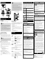
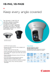
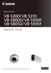
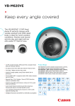
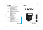
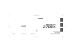
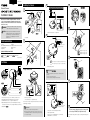
BIE-7004-001 ENGLISH Network Camera Installing the Camera 3 5 1 / / Installation Guide e a Please be sure to read the “Safety Precautions” section for correct use. After reading this Installation Guide, keep it in a readily accessible location for future reference. This camera is for indoor use only. d Ceiling Installation a WARNING To reduce a risk of fire or electric shock, do not 6 FRONT expose this product to rain or moisture. Caution Request a professional installer for all camera Wall Installation installation work. Never try to install the camera yourself. Doing so may result in unforeseen accidents such as dropping the camera or electric shock. d. Anchor or Structure / e. Safety Wire 4 a. Template f 2 Check Included Items Camera Template (VB-S30D/VB-S31D/VB-S800D) Installation Guide (This document) Setup CD-ROM Warranty Card Safety Wire Notice Please see the reverse side of this guide for details. Weight: Symbols Indicating Camera Model Camera specific functions will be listed using the icons below. : VB-S30D : VB-S31D © CANON INC. 2013 : VB-S800D 7 g Printed in Taiwan Approx. 270 g (9.6 oz.) Approx. 270 g (9.6 oz.) Approx. 240 g (8.5 oz.) LED : When powered on, during reboot, during normal use Part Names : When [Turn Off] is selected (see “Operation Guide”) 4 5 6 1 2 f. LAN cable / g. LED If Using a Memory Card Important The camera head will move and make noise when the power is turned on. 3 • Do not touch the camera head. • After the head stops moving, mount the camera. FRONT If Using the External Device Terminal or Audio Terminal 7 9 h 8 Serial_ _ _ _ _ _ _ _ _ _ _ _ _ _ _ _ _ b MAC_ _ _ _ _ _ _ _ _ _ _ _ _ _ _ _ _ _ 1. Camera Head / 2. Top Cover / 3. Memory Card Slot Cover / 4. Audio Input Terminal / 5. External Device I/O Terminal / 6. 100BT LAN Connector / 7. Safety Wire Attachment / 8. Tripod Mounting Screw Hole (a 1/4-20 UNC tripod mounting screw less than 5.5 mm (2.2 in.) in length will fit the screw hole) / 9. Rotation Dial 8 i j k c b. Memory Card Slot / c. Reset Switch (see “Operation Guide”) To remove the memory card, push it in and release it. The memory card will pop out slightly. Important •Insert a memory card before installing the camera. •When using a memory card with the camera for the first time, it is recommended to format the card after inserting it into the camera (see “Operation Guide”). Please see the reverse side of this guide for details. h. Protective Cover for Audio Input Terminal / i. Audio Input Terminal / j. Protective Cover for External Device I/O Terminal / k. External Device I/O Terminal 9 Perform camera settings by using the software found on the Setup CD-ROM (see “Operation Guide”). The contents of this guide are subject to change without any prior notice. External Dimensions 54 (2.13) 0( 43.2 (1.70) 3- 4.4 ( 0.17) (mounting screw holes) 21.0 (0.83) 54.5 (2.15) 4.7 11.0 (0.43) 53.5 (2.11) 50.0 (1.97) 2) •The External Device I/O Terminal consists of three terminals (IN, OUT, and GND). The GND terminal serves as both the external device input GND and the external device output GND. •The GND terminal is connected to the camera interior GND. •When using the external device input and output at the same time, couple the GND wire from the input cable with the GND wire from the output cable, conforming to the rating range, and connect it to the GND terminal. •Do not push the external device I/O terminal button with too much force. Doing so may cause the button to remain pushed-in. Internal Connection Diagram 1 kΩ 10 kΩ 10 kΩ IN 9.5 (0.37) Internal controller R0 .91 ) R2 3( 12 Unit : mm (in.) 0.1 µF See “Specifications” > “Others” > “Power Supply”. Important •Check with your dealer for more information about PoE devices. •Some PoE devices allow current limits for each port, but applying limits may interfere with performance. If using this type of PoE device, do not limit the operating current. •Some PoE devices have total consumption current limits for ports, which can interfere with performance when multiple ports are in use. For more information, check the instruction guide for your PoE device. External Device I/O Terminals External Device Input Terminals (IN) The external device input terminal consists of a positive terminal (IN) and negative terminal (GND). Connecting cables to the positive and negative terminals and opening or closing the circuit notifies the Viewer. Important When connecting sensors and switches, use those that have terminals which are isolated from internal power and GND. External Device Output Terminals (OUT) The external device output terminal consists of an OUT terminal and a GND terminal. Controls from the viewer can be used to open and close the circuit between the terminals. A MOSFET device is used for the output terminal. Rating range for load connected to output terminals. Rating between output terminals: Maximum voltage 50 V DC Continuous load current at or below 100 mA On resistance: Below 1 Ω Adaptive wiring for external device cables Rating Range: (same for contact input and output) Conductor Size: 0.42 – 0.80 mm ( 0.017 – 0.031 in.) dia. (AWG: No. 26 – 20) Stripped cable length should be approximately 11 – 13 mm (0.43 – 0.51 in.) This Installation Guide uses the following marks to indicate important information the user should know in order to use the product safely. In this section, explanations are provided for each mark so that readers will understand the level of importance for each. Be sure to observe these items. Warning Failure to follow the instructions accompanied by this symbol may result in death or serious injury. Caution Failure to follow the instructions accompanied by this symbol may result in injury. Caution Input terminal GND OUT Failure to follow the instructions accompanied by this symbol may result in property damage. This symbol indicates important or Important restricted items. Output terminal Note Connecting the Camera Power Supply Caution Symbols Indicating Safety Precautions Note Contains reference information for operation or additional explanations. GND Audio Input Terminals Camera has single audio input system supporting two types of microphone input: LINE IN and MIC IN. Before use, change [Audio Input] on the Setting Page (see “Operation Guide”). LINE IN is selected by default. •Dynamic MIC IN Input impedence: 20 kΩ – 40 kΩ •Condenser MIC IN Input impedence (microphone bias resistance): 2.2 kΩ ±20% Microphone power supply: plug-in power (voltage: 2.3 V) *Supported microphones: Condenser microphones with plug-in power support •LINE IN Input level: up to 1 Vp-p * Use a microphone with an amplifier. Installation Precautions Warning Do not install in the following places: •Places in strong direct sunlight, near heat-generating objects, or subject to high temperatures •Places near fire sources or flammable solvents (alcohol, thinner, fuel, etc.) •Humid or dusty places •Places subject to oily smoke or steam •Places subject to sea air •Confined or enclosed places Fire or electric shock may result. Specifications Please refer to the installation procedures or Operation Guide for specifications not listed below. Precautions for the LAN (power) cable: •Do not set any heavy objects on the LAN cable. •Do not pull, forcibly bend, scratch, or modify the LAN cable. Fire or electric shock may result. Camera Lens Safety Precautions 3.5x optical (4x digital zoom) zoom lens with auto focus Fixed focal length lens (4x digital zoom) Viewing Angle Horizontal: 77.7° (W) – 20.7° (T) Vertical: 40.4° (W) – 11.6° (T) Horizontal: 95.0°, Vertical: 60.0° Pan Angle Range 350° (±175°) Tilt Angle Range 90º (ceiling-mounted position: -90º – 0º) When the horizontal direction of the camera is 0° Rotation Angle Range 180° (±90°) Interface Network Terminal* LAN x 1 (RJ45, 100Base-TX (auto/full-duplex/half-duplex)) Audio Input Terminal (common for LINE IN & MIC IN) External Device I/O Terminal Memory Card 3.5 mm ( 0.14 in.) mini-jack connector (monaural) LINE IN x 1 or MIC IN x 1 Input x 1, Output x 1 micro SD Memory Card, micro SDHC Memory Card, micro SDXC Memory Card compatible. *LAN cables are category 5 or higher, with length 100 m (328 ft.) or shorter. Others Operating Environment Temperature: -10°C – +50°C (+14°F – +122°F), Humidity: 5% – 85% (without condensation) Storage Environment Temperature: -30°C – +60°C (-22°F – +140°F), Humidity: 5% – 90% (without condensation) ±5° (camera) in relation to a horizontal plane Installation Angle Power Supply PoE: PoE power supply via LAN connector (IEEE802.3af compliant) Power Consumption Max. 7.8 W Max. 7.6 W Max. 4.1 W Caution For installation or inspection of this camera, consult the dealer where you purchased the product. •This installation should be made by a qualified service person and should conform to all local codes. •When installing on a ceiling, make sure the surface is capable of withstanding the total weight of the ceiling mount cover and the camera, and is sufficiently reinforced if necessary. •Be sure to use installation screws designed for the type of ceiling the camera is to be installed. •Periodically check the parts and screws for rust and to see if they have loosened, in order to prevent injuries and equipment damage due to falling items. •Do not install in unstable places, places subject to significant vibration or impact, or places subject to salt damage or corrosive gas. •Be sure to attach the safety wire when installing the camera. Failure to do so may result in the camera falling or other accidents. •Do not touch the edges of metal parts with bare hands. •Be careful not to trap your fingers during installation of the camera. Injury may result. • • Do not turn the camera rotator by hand. Do not install on an unstable surface. Also, make sure the camera is installed ±5°off horizontal. •After turning off the power, do not turn the power on again for at least 5 seconds. •Take measures to remove static electricity before performing any procedures. Malfunction may result. •Take care not to damage wiring or pipes in the room. Damage to peripheral items may result. Precautions for Use Warning •If you discover defective conditions such as smoke, strange sounds, heat or strange odors, immediately stop using the camera and contact your nearest dealer. Fire or electric shock may result from continued use of the product. •Do not disassemble or modify the camera. •Do not damage the connecting cable. •Do not spill water or other liquid inside the camera, spray the camera with water, or otherwise make it wet. •Do not insert foreign objects into the camera. •Do not use flammable sprays near the camera. •Do not leave LAN cables connected when the camera is not in use for long periods. •Do not use flammable solvents such as alcohol, paint thinner or benzine when cleaning the camera. Fire or electric shock may result. Only for European Union and EEA (Norway, Iceland and Liechtenstein) These symbols indicate that this product is not to be disposed of with your household waste, according to the WEEE Directive (2012/19/EU), the Battery Directive (2006/66/EC) and/or national legislation implementing those Directives. If a chemical symbol is printed beneath the symbol shown above, in accordance with the Battery Directive, this indicates that a heavy metal (Hg = Mercury, Cd = Cadmium, Pb = Lead) is present in this battery or accumulator at a concentration above an applicable threshold specified in the Battery Directive. This product should be handed over to a designated collection point, e.g., on an authorized one-for-one basis when you buy a new similar product or to an authorized collection site for recycling waste electrical and electronic equipment (EEE) and batteries and accumulators. Improper handling of this type of waste could have a possible impact on the environment and human health due to potentially hazardous substances that are generally associated with EEE. Your cooperation in the correct disposal of this product will contribute to the effective usage of natural resources. For more information about the recycling of this product, please contact your local city office, waste authority, approved scheme or your household waste disposal service or visit www.canoneurope.com/weee, or www.canon-europe.com/battery. CANON INC. 30-2, Shimomaruko 3-chome, Ohta-ku, Tokyo 146-8501, Japan CANON EUROPA N.V. Bovenkerkerweg 59, 1185 XB Amstelveen, The Netherlands