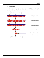
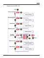
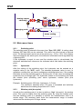
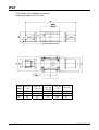
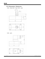
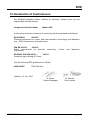
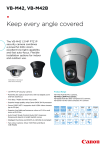
1
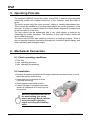
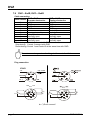
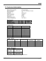
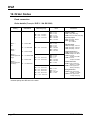
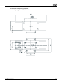
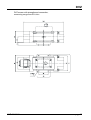
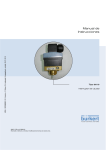
Operating Instructions for Compact Vortex Flow Meter Model: DVZ DVZ 1. Contents 1. 2. 3. 4. 5. 6. Contents ........................................................................................................ 2 Note .............................................................................................................. 3 Instrument Inspection .................................................................................... 3 Regulation Use.............................................................................................. 3 Operating Principle........................................................................................ 4 Mechanical Connection ................................................................................. 4 6.1 Check operating conditions:................................................................. 4 6.2 Installation............................................................................................ 4 7. Electrical Connection .................................................................................... 5 7.1 General ................................................................................................ 5 7.2 DVZ-...S300 ......................................................................................... 6 7.3 DVZ-...S30D ........................................................................................ 6 7.4 DVZ-...F300; DVZ-...L3x3 .................................................................... 6 7.5 DVZ-...L443 ......................................................................................... 7 7.6 DVZ-...C30 ........................................................................................... 7 7.7 DVZ-...C34 ........................................................................................... 7 7.8 DVZ-...Ex4R, DVZ-...Gx4R .................................................................. 8 8. Operation ...................................................................................................... 9 8.1 Switch point setting DVZ-...S300, DVZ-…S30D .................................. 9 8.2 Counter electronics DVZ-…Ex4R ........................................................ 9 8.3 Dosing electronics DVZ-…Gx4R ......................................................... 9 9. Adjustments – Compact Electronic DVZ-...C3.. .......................................... 10 9.1 Button function ................................................................................... 10 9.2 Settings .............................................................................................. 10 9.3 Value setting ...................................................................................... 11 9.4 Set-up mode ...................................................................................... 12 9.5 Main menu items ............................................................................... 14 10. Maintenance ............................................................................................... 16 11. Technical Information .................................................................................. 17 12. Order Codes ............................................................................................... 20 13. Dimensions ................................................................................................. 22 13.1 Dimensions - Sensor.......................................................................... 22 13.2 Dimensions - Electronics ................................................................... 28 14. Declaration of Conformance ....................................................................... 31 Manufactured and sold by: Kobold Messring GmbH Nordring 22-24 D-65719 Hofheim Tel.: +49(0)6192-2990 Fax: +49(0)6192-23398 E-Mail: [email protected] Internet: www.kobold.com page 2 DVZ K04/0810 DVZ 2. Note Please read these operating instructions before unpacking and putting the unit into operation. Follow the instructions precisely as described herein. The devices are only to be used, maintained and serviced by persons familiar with these operating instructions and in accordance with local regulations applying to Health & Safety and prevention of accidents. When used in machines, the measuring unit should be used only when the machines fulfil the EWG-machine guidelines. as per PED 97/23/EG In acc. with Article 3 Paragraph (3), "Sound Engineering Practice", of the PED 97/23/EC no CE mark. Diagram 8, Pipelines, Group 1, dangerous fluids 3. Instrument Inspection Instruments are inspected before shipping and sent out in perfect condition. Should damage to a device be visible, we recommend a thorough inspection of the delivery packaging. In case of damage, please inform your parcel service / forwarding agent immediately, since they are responsible for damages during transit. Scope of delivery: The standard delivery includes: • Compact Vortex Flow Meter • Operating Instructions model: DVZ 4. Regulation Use Any use of the Compact Vortex flow meter, model: DVZ, which exceeds the manufacturer’s specifications, may invalidate its warranty. Therefore, any resulting damage is not the responsibility of the manufacturer. The user assumes all risk for such usage. DVZ K04/0810 page 3 DVZ 5. Operating Principle The compact KOBOLD Vortex flow meter, model DVZ, is used for measuring and monitoring smaller and medium-sized flow of low viscosity, water-like fluids in pipes. The device works using the vortex process, making it virtually maintenance-free. This involves the installation of a sharp-edged object (the vortex generator) in the flow duct. A vortex is created behind the object whose frequency is proportional to the flow velocity of the fluid. The flow volume can be determined with a very great degree of accuracy by measuring the vortex frequency. This achieves a very high linearity across the whole measuring range. The device can be fitted with switching, frequency or analogue outputs. There is also an optional compact electronics package that includes a digital display, and both a switching and analogue output. 6. Mechanical Connection 6.1 Check operating conditions: • Flow rate • max. operating pressure • max. operating temperature 6.2 Installation • Remove all packing materials and transport retainers and ensure that no such materials remain in the device. • Install with flow in direction of arrow (universal mounting) • Avoid pressure and radial tension • Fasten the pipe at up stream and down stream at a distance of 50 mm from the connections Attention! Retransfer the unit on the metal bolting (not on the plastic housing!) Mount switches using the proper tightening torque according the following table! page 4 DVZ K04/0810 DVZ Nominal size of threads 3/8” 1/2” 3/4” 1” Proper tightening torque 22 bis 24 Nm 28 bis 30 Nm 28 bis 30 Nm 36 bis 38 Nm Note! The switch may be damaged if it is tightened above the tightening torque range. Also, if it is tightened below the tightening torque range, the connecting thread section may loosen. • Ensure inlet section of 10xDN and outlet section of 10xDN • Avoid valves or large reduction on the inlet section (this increases the inaccuracy of measurements) • Check the seals of the connections Attention! When used with an open output side, there is a danger of cavitation. 7. Electrical Connection 7.1 General Attention! Make sure that the voltage values of your system correspond with the voltage values of the measuring unit. • Make sure that the supply wires are de-energised. • Connect the supply voltage and the output signal to the plug PIN’s as stated below. • We recommend the use of wires with cross sectional area of min. 0,25 mm². DVZ K04/0810 page 5 DVZ 7.2 DVZ-...S300 2 Output N/O 1 5 GND 3 +Vs Output Common Output N/C 4 7.3 DVZ-...S30D 2 Output N/C GND 3 1 +Vs 4 Output N/O 7.4 DVZ-...F300; DVZ-...L3x3 Connection example DVZ-...L3x3 +Vs n.c. 2 n.c. 1 +Vs GND GND page 6 3 GND 2 1 +Vs 3 Signal 4 Out Signal 4 Out DVZ K04/0810 DVZ 7.5 DVZ-...L443 +Vs +Vs Signal Out GND GND 7.6 DVZ-...C30 2 Switch Out 2 1 +Vs GND 5 GND 3 Switch Out 1 4 7.7 DVZ-...C34 1 0(4)-20 mA 2 GND 5 GND DVZ K04/0810 3 +Vs 4 Switch out 1 page 7 DVZ 7.8 DVZ-...Ex4R, DVZ-...Gx4R Cable connection DVZ-...E14R DVZ-...G14R Wire number Counter electronics Dosing electronics 1 +24 VDC +24 VDC 2 GND GND 3 4-20 mA 4-20 mA 4 GND GND 5 n. c. control 2* 6 reset part quantity control 1* 7 relay S1 relay S1 normally open normally open 8 9 relay S2 relay S2 normally open normally open 10 *Start-dosing: Control 1 connect with GND Stop-dosing: Control 2 connect with GND Reset-dosing: Control 1 and Control 2 at the same time with GND Do not connect any external voltage to the control units! Plug connection -E34 R 0 (4) - 20 mA + Vs Output 1 Reset TM 5 4 d.c. *) 3 GND 30 VAC/DC / 2 A 1 3 8 S2 6 4 5 d.c.*) Don't connect! page 8 DVZ K04/0810 DVZ 8. Operation The units are preset and after electrical connection ready for operation. 8.1 Switch point setting DVZ-...S300, DVZ-…S30D Switch setting 0 1 2 3 4 5 6 7 8 9 Switch point switch function deactivated start of measuring range 20% of f.s. 30% of f.s. 40% of f.s. 50% of f.s. 60% of f.s. 70% of f.s. 80% of f.s. 90% of f.s. Flow above switch point: DUO-LED green Flow below switch point: DUO-LED red Measuring range overflow: DUO-LED orange flashing 8.2 Counter electronics DVZ-…Ex4R Operating please see Operating Instructions ZED-Z 8.3 Dosing electronics DVZ-…Gx4R Operating please see Operating Instructions ZED-D DVZ K04/0810 page 9 DVZ 9. Adjustments – Compact Electronic DVZ-...C3.. Connect the compact electronic according to previous connection diagram. After power on, the measuring range (end current) will be shown for 3 seconds. 9.1 Button function In the normal mode (measuring mode) : Press 3 sec. Setup mode : Switch point/Window point In the set-up mode : Next Step : Change Value Any time 3 Isec d or do not press a button for 20 sec Standard mode M d 9.2 Settings The following values can be changed at the temperature transmitter: Scale range 0...999 Switch point (SPo, SP1, SP2) -199...0 Hysteresis (HYS) Switch point ...999 Window point (duo point) (duo) contact-type (Con, Co1, Co2) N/O, N/C or Frequency (Fr)** 000...999 Start current (S-C)* 000...999 End current (E-C)* 0-- (0 mA), 4-- (4 mA) Start current selection (SCS) 000...999 Change Code (CCo) * Start- and end value of flow relating to 0/4-20 mA. ** not calibrated, frequency at f.s. approx. 500 -600Hz page 10 Factory setting 0,00 -0,00 --- (inactive) N/O 000 f.s. 4 mA 000 DVZ K04/0810 DVZ 9.3 Value setting From the main menu item (for example: switch point, "SPo"), press the "" button to set the value. The flow chart below illustrates the universal routine for changing individual parameters. [From the main menu item] 1. Adjust position 2. Adjust position 3. Adjust position Adjust decimal point save Save selected value or enter new value. [To the next main menu item] DVZ K04/0810 page 11 DVZ 9.4 Set-up mode Compact electronic DVZ-...C30.. 3 sec Code entering Code= Value setting Switching point 1 Value setting Switching point 2 Value setting Hysteresis Value setting Contact 1 function Contact 2 function N/C Frequency Save N/O N/C Save Code entering Value setting page 12 DVZ K04/0810 DVZ Compact electronic DVZ-...C34 3 sec Code entering Code= Value setting Switching point Value setting Hysteresis Value setting Window point Value setting Contact function N/O N/C Frequency Save Start current 7sec Value setting End current 7sec Value setting DVZ K04/0810 page 13 DVZ Analog output choosing 0-20 mA 7sec 4-20 mA Storing Changing code Value setting 9.5 Main menu items 9.5.1 Switching point The switching point is entered in the menu item "Spo, SP1, SP2". A setting value between 000 and 999 can be selected. This value can also include a decimal point. The decimal point can be set at two points (e.g. 10.0 or 1.00). If the display value exceeds the set switch point, the electronic is activated and is signalised by a lightning LED. If the hysteresis is equal to zero and the window point is de-activated, the electronic switches back whenever the indicated value falls below the switching point. 9.5.2 Hysteresis After the setting of the switching point, the hysteresis can be entered as a negative value in the "HYS" menu. The standard hysteresis value is zero. In operation condition this can lead to ambiguous switching behaviour, if the reading fluctuates around the switching point or window point. In this case, increasing the hysteresis can put things right. The hysteresis relates to the switching point and the window point (switching point minus hysteresis; window point plus hysteresis). Example: Switching point 100 l/min; Hysteresis: -2.5 l/min The electronic switches when 100 l/min is exceeded and switches back when the reading drops below 97.5 l/min. 9.5.3 Window point (duo-point) As well as the switching point, it is also to define a "duo" (duo-point), the window point. This must be higher than the switching point. By using the window point and the switching point it is possible to monitor the measurement value in a certain range. The switching point limits the measurement range to smaller values and the window point to larger values. page 14 DVZ K04/0810 DVZ If the window point (duo-point) is less than or equal to the switching point, an error report (Er4) will be indicated on the display and its value is deleted and its function is invalid (in the case that the window point and switching point out of adjustment). The value is set in the same way as the switching point. The window point is needed for process, in which monitoring of a certain temperature range is necessary. Example: Switching point: 100 L/min; window point: 150 L/min; hysteresis: -1 L/min The electronic switches when 100 l/min is exceeded. If the switching value remains between 99 L/min (100-1) and 151 L/min (150+1), the contact will also remain in active switching condition (LED on). If it exceeds 151 l/min or is below 99 l/min the electronic switches back. Switching behaviour The following diagram clarifies the switching behaviour of the electronic switch. The contact closes (contact type: no) when it drops below the switching point or the window point. It only opens again if the window point plus hysteresis is exceeded or if it drops below the switching point minus hysteresis. An LED indicates the switching condition of the switching point. Display bar (°C) LED on Hysteresis Time / t Display bar (°C) LED on Hysteresis Window point LED on Switchpoint Hysteresis Time / t DVZ K04/0810 page 15 DVZ 9.5.4 Contact type The function of the transistor switching output is set in menu item "Con, Co1 or Co2". The switching function switches from no - N/O contact to nc - N/C to Fr – frequency (only Con and Co1) and back. N/O contact: contact closes when switching point is exceeded N/C contact: contact opens when switching point is exceeded Frequency: frequency output synchronised with the vane frequency 9.5.5 Current output The current output is selected in menu items "S-C" Start current indicated value < > 0(4) mA "E-C" End current indicated value < > 20 mA "SCS" Start current selection (0-20 mA or 4-20 mA). The indicated value at which 0(4) mA flow is entered in menu item Start current. The indicated value at which 20 mA flow is entered in menu item End current. 9.5.6 Change Code The change code option "CCo" secures the unit against unauthorised tampering. If the code is different from 000, the user must input the code immediately after entering the adjustment mode. 10. Maintenance The measurement device requires no maintenance if the measurement medium does not cause deposits or include fibre parts, which wrap around the sensor or the gate. In order to avoid problems, we recommend the installation of a filter, such as the magnetic filter, type MFR. If it is necessary to clean the sensor, the sensor can be rinsed with a suitable liquid. Fiber parts or large particles can be carefully removed with tweezers, etc. Ensure that the sensor is not damaged. Work on the electronics can only be performed by the factory, or the warranty is otherwise voided. page 16 DVZ K04/0810 DVZ 11. Technical Information Measurement process: Mounting position: Response time: Accuracy: Repeat accuracy: Inlet / outlet runs: Protection: Media temperature: Ambient temperature: Vortex principle any, flow in direction of arrow 1s ±2.5% of f.s. ±1% of f.s. 10xDN IP 65 0...80 °C -10...+60 °C Max. Pressure Connection Standard version Reinforced version fixed 10 bar 20 bar rotatable 20 bar - Pressure loss Model DVZ-**04 DVZ-**07 DVZ-**10 DVZ-**16 DVZ-**22 DVZ-**32 DVZ-**40 DVZ-**50 DVZ-**63 DVZ-**80 DVZ-**99 Upper range value 4,5 L/min 6,5 L/min 10,0 L/min 16,0 L/min 22,0 L/min 32,0 L/min 40,0 L/min 50,0 L/min 63,0 L/min 80,0 L/min 100,0 L/min Pressure loss 420 mbar 650 mbar 780 mbar 600 mbar 450 mbar 370 mbar 450 mbar 400 mbar 380 mbar 400 mbar 350 mbar Weight - Sensor Measuring range bis 32 L/min bis 32 L/min bis 32 L/min 40...100 L/min 40...100 L/min Size Connection fixed ¼", 3/8", ½" ¾" 1" ¾" 1" approx. 450 g approx. 600 g approx. 1050 g approx. 1050 g approx. 900 g Connection strengthened approx. 600 g approx. 600 g approx. 950 g approx. 1300 g approx. 1150 g Connection rotatable approx. 800 g approx. 900 g approx. 950 g approx. 1350 g approx. 1400 g Weight - Electronics Model DVZ-...F3x0 DVZ-...S30x DVZ-...Lxx3 DVZ-...C3xx DVZ-...Exxx DVZ-...Gxxx Weight approx. 80 g approx. 300 g approx. 250 g Total weight = weight sensor + weight electronics DVZ K04/0810 page 17 DVZ Wetted parts Sensor housing: Sensor: Connections: Bluff body: Seal: DVZ-...S300, DVZ-…S30D Display: Switching output: Switch point: Power supply: Power consumption: Electrical connection: Measuring range overflow: DVZ-...F300, DVZ-…F390 Impulse output: Frequency at f.s. PPS, fibreglass-reinforced PVDF brass (from 32 L/min nickel plated from 40 L/min blank) or stainless steel 1.4404 PPS, fibreglass-reinforced or oxide ceramic (non-wear version) NBR, EPDM or FPM duo-LED for switching condition and when range limit is exceeded relay changeover, max. 1 A/30 VDC or active 24 VDC, N/C / N/O measuring range beginning from 90% f.s. in 10%-steps can be configured by the customer using a rotary switch 24 VDC ± 20% 12 mA plug M12x1.5 pole flash of the DUO-LED (red/green) from 105 % of f.s. Power supply: Power consumption: Electrical connection: Measuring range overflow: PNP, Open Collector, max. 200 mA 500 Hz (…F300) 50…1000 Hz (F390) 24 VDC ± 20% 5 mA plug M12x1 Fout approx. 2 kHz from 105 % of f.s. DVZ-...L303; DVZ-...L343 Output: Max. load: Power supply: Electrical connection: Measuring range overflow: 0(4)-20 mA, 3-wire 500 Ω 24 VDC ± 20% plug M12x1 Iout approx. 20,5 mA from 103 % of f.s. DVZ-...L443 (usage with AUF-3000) Output: 4-20 mA, 3-wire Max. load: 500 Ω Power supply: 24 VDC ± 20% Electrical connection: plug DIN 43650 Measuring range overflow: Iout approx. 20,5 mA from 103 % of f.s. page 18 DVZ K04/0810 DVZ DVZ-...C3 (Compact electronics)* Display: 3-digit LED Analogue output: (0)4...20 mA adjustable, max. 500 Ω (only DVZ-…C34*) Switching output: 1 or 2 Open Collector PNP or NPN, set at factory, max. 300 mA Contact function: N/C, N/O, frequency, programmable (frequency output not calibrated, frequency at f.s. approx. 500 -600Hz) Programming: with 2 keys Power supply: 24 VDC ± 20%, 3-wire Power consumption: approx. 100 mA Electrical connection: plug M12x1 Measuring range overflow: display “OF” from 105% of f.s. DVZ-...Exxx (Counter electronics)* Display: LCD, 2x8 digit, illuminated total, part and flow quantities, units selectable Quantity meter: 8-digit Analogue output: (0)4...20 mA adjustable Load: max. 500 Ω Switching output: 2 relays, max. 30 VAC/DC / 2 A / 60 VA Settings: via 4 buttons Functions: reset, MIN/MAX memory, flow monitor, monitoring for part and total quantity, language Power supply: 24 VDC ±20 %, 3-wire Power consumption: approx. 150 mA Electrical connection: cable connection or M12-plug DVZ-...Gxxx (Dosing electronics)* Display: LCD, 2x8 digit, illuminated, dosing, total and flow quantity, units selectable Quantity meter: 8-digit Dosage: 5-digit Analogue output: (0)4...20 mA adjustable Load: max. 500 Ω Switching output: 2 relays, max. 30 VAC/DC / 2 A / 60 VA Settings: via 4 buttons Functions: dosing (relay S2), start, stop, reset, fine dosing, correction amount, flow switch, total quantity, language Power supply: 24 VDC ±20 %, 3-wire Power consumption: approx. 150 mA Electrical connection: cable connection or M12-plug *more technical details see data sheet ZED in the brochure Z2 DVZ K04/0810 page 19 DVZ 12. Order Codes Fixed connection Order details (Example: DVZ-1 1 04 G2 S300) Storage body/ housing DVZ-1.. = PPS Connection material/seal ..04.. = 0.5 - 4.5 L/min ..07.. = 0.8 - 7.0 L/min ..10.. = 1.3 - 10.0 L/min ..G2.. = G 1/4 ..G3.. = G 3/8 ..G4.. = G 1/2 ..N2.. = 1/4 NPT ..N3.. = 3/8 NPT ..N4.. = 1/2 NPT ..16.. = 2.0 - 16.0 L/min ..G3.. = G 3/8 ..G4.. = G 1/2 ..G5.. = G 3/4 ..N3.. = 3/8 NPT ..N4..= 1/2 NPT ..N5.. = 3/4 NPT ..1.. = brass/ NBR ..2.. = st. steel/ NBR DVZ-2.. = ceramic ..4.. = brass/ EPDM DVZ-3..*= PPS/strengthened design ..5.. = st. steel/ EPDM ..7.. = brass/ FPM DVZ-4..*= ceramic/strengthe ned design Connection fixed Measuring range ..22.. = 3.2 - 22.0 L/min ..32.. = 4.0 - 32.0 L/min ..G4.. = G 1/2 ..G5.. = G 3/4 ..G6.. = G 1 ..N4.. = 1/2 NPT ..N5.. = 3/4 NPT ..N6.. = 1 NPT ..8.. = st. steel/ FPM ..40.. = 4,0 - 40,0 L/min ..50.. = 5,0 - 50,0 L/min ..63.. = 6,3 - 63,0 L/min ..80.. = 8,0 - 80,0 L/min ..G5.. = G 3/4 ..G6.. = G 1 ..N5.. = 3/4 NPT ..N6.. = 1 NPT ..99.. = 10,0 - 100 L/min Electronics switching output ..S300 = relay, M12-plug ..S30D =active 24 VDC, M12-plug frequency output ..F300 =M12-plug, 500 Hz ..F390 =M12-plug, 50…1000 Hz analogue output ..L303 =M12-plug, 0-20 mA ..L343 =M12-plug, 4-20 mA ..L443 =DIN-plug, 4-20 mA compact electronics** ..C30R =2xOpen Coll. PNP ..C30M =2xOpen Coll. NPN ..C34P =4-20 mA, 1xOpen Coll. PNP ..C34N =4-20 mA, 1xOpen Coll. NPN counter electronics ..E14R =LCD, 0(4)-20 mA, 2xrelay, 1 m cable ..E34R =LCD, 0(4)-20 mA, 2xrelay, M12-plug dosing electronics ..G14R =LCD, 0(4)-20 mA, 2xrelay, 1 m cable ..G34R =LCD, 0(4)-20 mA, 2xrelay, M12-plug *Reinforced version only in combination with fixed connection **Please specify flow direction in the order page 20 DVZ K04/0810 DVZ Axial rotatable connection Storage body/ housing Connection material/ Seal Measuring range DVZ-1.. = PPS DVZ-2.. = ceramic ..B2.. = G 1/4 ..B3.. = G 3/8 ..B4.. = G 1/2 ..P2.. = 1/4 NPT ..P3.. = 3/8 NPT ..P4.. = 1/2 NPT switching output ..S300 =relay, M12-plug ..S30D =active 24 VDC, M12-plug ..16.. = 2.0 - 16.0 L/min ..B3.. = G 3/8 ..B4.. = G 1/2 ..B5.. = G 3/4 ..P3.. = 3/8 NPT ..P4..= 1/2 NPT ..P5.. = 3/4 NPT analogue output ..L303 =M12-plug, 0-20 mA ..L343 =M12-plug, 4-20 mA ..L443 =DIN-plug, 4-20 mA ..4.. = brass/ EPDM ..5.. = st. steel/ EPDM ..7.. = brass/ FPM Electronics ..04.. = 0.5 - 4.5 L/min ..07.. = 0.8 - 7.0 L/min ..10.. = 1.3 - 10.0 L/min ..1.. = brass/ NBR ..2.. = st. steel/ NBR Connection rotatable ..22.. = 3.2 - 22.0 L/min ..32.. = 4.0 - 32.0 L/min ..8.. = st. steel/ FPM ..B4.. = G 1/2 ..B5.. = G 3/4 ..B6.. = G 1 ..P4.. = 1/2 NPT ..P5.. = 3/4 NPT ..P6.. = 1 NPT ..40.. = 4,0 - 40,0 L/min ..50.. = 5,0 - 50,0 L/min ..63.. = 6,3 - 63,0 L/min ..80.. = 8,0 - 80,0 L/min ..99.. = 10,0 - 100 L/min ..B5.. = G 3/4 ..B6.. = G 1 ..P5.. = 3/4 NPT ..P6.. = 1 NPT frequency output ..F300 =M12-plug. 500 Hz ..F390 =M12-plug, 50…1000 Hz compact electronics* ..C30R =2xOpen Coll. PNP ..C30M=2xOpen Coll. NPN ..C34P =4-20 mA, 1xOpen Coll. PNP ..C34N =4-20 mA, 1xOpen Coll. NPN counter electronics ..E14R =LCD, 0(4)-20 mA, 2xrelay, 1 m cable ..E34R =LCD, 0(4)-20 mA, 2xrelay, M12-plug dosing electronics ..G14R =LCD, 0(4)-20 mA, 2xrelay, 1 m cable ..G34R =LCD, 0(4)-20 mA, 2xrelay, M12-plug *Please specify flow direction in the order DVZ K04/0810 page 21 DVZ 13. Dimensions 13.1 Dimensions - Sensor AF DVZ-sensor with fixed connection, measuring range up to 32 L/min for Meas. ..04/..07/..10 range D1 1/4" AF 35 L1 100 L2 -L3 35 L4 -- page 22 ..04/..07/ ..10/..16 3/8" 35 100 -35 -- ..04/..07/..10/ ..16/..22/..32 ..16/..22/..32 1/2" 3/4" 35 34 106 120 -50 35 34 --- ..22/..32 1" -128 50 -46 DVZ K04/0810 DVZ AF DVZ-sensor with fixed connection, measuring range from 40 L/min o DVZ K04/0810 page 23 DVZ AF DVZ-sensor with strengthened connection, measuring range up to 32 L/min for Meas. ..04/..07/..10 range D1 1/4" AF 34 L1 100 L4 34 page 24 ..04/..07/ ..10/..16 3/8" 34 100 34 ..04/..07/..10/ ..16/..22/..32 1/2" 34 106 34 ..16/..22/..32 ..22/..32 3/4" 34 120 34 1" -128 46 DVZ K04/0810 DVZ AF DVZ-sensor with strengthened connection, measuring range from 40 L/min o DVZ K04/0810 page 25 DVZ DVZ-Sensor with rotatable connection, measuring range up to 32 L/min o Meas. ..04/..07/ range ..10 D1 D2 AF page 26 1/4" 24 19 ..04/..07/ ..10/..16 3/8" 28 24 ..04/..07/ ..16/..22/ ..10/..16/ ..22/..32 ..32 ..22/..32 1/2" 3/4" 1" 35 40 45 30 36 41 DVZ K04/0810 DVZ AF DVZ-Sensor with rotatable connection, measuring range from 40 L/min o Meas. range D1 D2 AF DVZ K04/0810 ..40/..50/ ..60/..80/ ..99 3/4" 40 36 ..40/..50/ ..60/..80/ ..99 1" 45 41 page 27 DVZ 13.2 Dimensions - Electronics DVZ-...S30x, DVZ-...F3x0, DVZ-...L3x3 DVZ-...L443 page 28 DVZ K04/0810 DVZ DVZ-...C3xx DVZ K04/0810 page 29 DVZ DVZ-...Exxx, DVZ-...Gxxx page 30 DVZ K04/0810 DVZ 14. Declaration of Conformance We, KOBOLD Messring GmbH, Hofheim-Ts, Germany, declare under our sole responsibility that the product: Compact Vortex Flow Meter Model: DVZ to which this declaration relates is in conformity with the standards noted below: EN 61326/A1 2004-05 Electrical equipment for control and instrumentation technology and laboratory use – EMC-requirements (industrial area) DIN EN 61010-1 1994-03 Safety requirements for electrical instruments. measuring-, control- and laboratory EN 60529, DIN VDE 0470-1 1992-11 Protection type housing (IP-Code) Also the following EEC guidelines are fulfilled: 2004/108/EC EMC Directive Hofheim, 16. Jan. 2007 H. Peters General Manager DVZ K04/0810 M. Wenzel Proxy Holder page 31