1
SmartCell ZX-250 User
Guide
35 Industrial Way
Rochester, NH 03866
USA
(603) 332-9400
Part Number 04-0034-04 Rev-A
Order Number 9032538
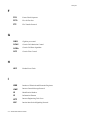
NOTICE
Cabletron Systems reserves the right to make changes in specifications and other information contained in this
document without prior notice. The reader should in all cases consult Cabletron Systems to determine whether any
such changes have been made. The hardware, firmware, and software described in this manual are subject to change
without notice.
IN NO EVENT SHALL CABLETRON SYSTEMS BE LIABLE FOR ANY INCIDENTAL, INDIRECT, SPECIAL,
OR CONSEQUENTIAL DAMAGES WHATSOEVER (INCLUDING, BUT NOT LIMITED TO, LOST PROFITS)
ARISING OUT OF OR RELATED TO THIS MANUAL OR THE INFORMATION CONTAINED IN IT, EVEN IF
CABLETRON SYSTEMS HAS BEEN ADVISED OF, KNOWN, OR SHOULD HAVE KNOWN, THE
POSSIBILITY OF SUCH DAMAGES.
Copyright 1997 - 98 by Cabletron Systems, Inc., P.O. Box 5005, Rochester, NH 03866-5005
All Rights Reserved
Printed in the United States of America
SmartCell ZX-250 User Guide
Part Number 04-0034-04 Rev-A
Order Number: 9032538
SmartCell, SPECTRUM, LANVIEW, MicroMMAC, and BRIM are registered trademarks and Element Manager,
EPIM, EPIMA, EPIM-F1, EPIM-F2, EPIM-F3, EPIM-T, EPIM-X, FOT-F, FOT-F3, HubSTACK, SEH, SEHI, and
TMS-3 are trademarks of Cabletron Systems, Inc. All other product names mentioned in this manual may be
trademarks or registered trademarks of their respective companies.
ii
SmartCell ZX-250 User Guide
FCC CLASS A NOTICE
This device complies with Part 15 of the FCC rules. Operation is subject to the following two conditions: (1) this
device may not cause harmful interference, and (2) this device must accept any interference received, including
interference that may cause undesired operation.
2p›F
This equipment has been tested and found to comply with the limits for a Class A
digital device, pursuant to Part 15 of the FCC rules. These limits are designed to
provide reasonable protection against harmful interference when the equipment is
operated in a commercial environment. This equipment uses, generates, and can
radiate radio frequency energy and if not installed in accordance with the
SmartCell ZX-250 User Guide, may cause harmful interference to radio
communications. Operation of this equipment in a residential area is likely to
cause interference in which case the user will be required to correct the
interference at his own expense.
>"•mamV
Changes or modifications made to this device which are not expressly
approved by the party responsible for compliance could void the user’s
authority to operate the equipment.
DOC CLASS A NOTICE
This digital apparatus does not exceed the Class A limits for radio noise emissions from digital apparatus set out in the
Radio Interference Regulations of the Canadian Department of Communications.
Le present appareil numerique n’emet pas de bruits radioelectriques depassant les limites applicables aux appareils
numeriques de la class A prescrites dans le Reglement sur le brouillage radioelectrique edicte par le ministere des
Communications du Canada.
SmartCell ZX-250 User Guide iii
DECLARATION OF CONFORMITY
ADDENDUM
Application of Council Directive(s):
89/336/EEC
73/23/EEC
Manufacturer’s Name:
Cabletron Systems, Inc.
Manufacturer’s Address:
35 Industrial Way
P. O. Box 5005
Rochester, NH 03866
Product Name:
SmartCell ZX-250
SmartCell ZX-250i
SmartCell ZX-250r
European Representative Name:
Mr. J. Solari
European Representative Address:
Cabletron Systems, Limited
Nexus House, Newbury Business Park
London Road, Newbury
Berkshire RG13 2PZ, England
Conformance to Directive(s)/Product Standards:
EC Directive 89/336/EEC
EC Directive 73/23/EEC
EN 55022
EN 50082-1
EN 60950
Equipment Type/Environment:
Networking Equipment, for use in a Commercial or Light
Industrial Environment.
We the undersigned, hereby declare, under our sole responsibility, that the equipment packaged with this
notice conforms to the above directives.
Manufacturer:
Full Name:
Title:
Location:
Mr. Ronald Fotino
Principal Compliance Engineer
Rochester, NH. U.S.A.
Legal Repersentative in Europe:
Full Name:
Title:
Location:
Mr. J. Solari
Managing Director - E.M.E.A.
Newbury, Berkshire, England
iv
SmartCell ZX-250 User Guide
SAFETY INFORMATION
CLASS 1 LASER TRANSCEIVERS
The ZX-IOM-29-4, ZX-IOM-29-4-IR, ZX-IOM-29-4-LR, ZX-IOM-39-1 and ZX-IOM-39-1-LR connectors use Class
1 Laser transceivers. Read the following safety information before installing or operating one of these modules.
The Class 1 Laser transceivers use an optical feedback loop to maintain Class 1 operation limits. This control loop
eliminates the need for maintenance checks or adjustments. The output is factory set, and does not allow any user
adjustment. Class 1 Laser transceivers comply with the following safety standards:
U
U
U
21 CFR 1040.10 and 1040.11 U. S. Department of Health and Human Services (FDA).
IEC Publication 825 (International Electrotechnical Commission).
CENELEC EN 60825 (European Committee for Electrotechnical Standardization).
When operating within their performance limitations, laser transceiver output meets the Class 1 accessible emission
limit of all three standards. Class 1 levels of laser radiation are not considered hazardous.
LASER RADIATION AND CONNECTORS
When the connector is in place, all laser radiation remains within the fiber. The maximum amount of radiant power
exiting the fiber (under normal conditions) is -12.6dBm or 55x10-6 watts.
Removing the optical connector from the transceiver allows laser radiation to emit directly from the optical port. The
maximum radiance from the optical port (under worst case conditions) is 0.8 W cm -2 or 8x10³ W m-2 sr-1.
Do not use optical instruments to view the laser output. The use of optical instruments to view laser output increases
eye hazard. When viewing the output optical port, you must remove power from the network adapter.
SmartCell ZX-250 User Guide v
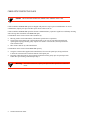
FIBER OPTIC PROTECTIVE CAPS
%"¤›apm
READ BEFORE REMOVING FIBER OPTIC PROTECTIVE CAPS.
Cable assemblies and MMF/SMF ports are shipped with protective caps to prevent contamination. To avoid
contamination, replace port caps on all fiber optic devices when not in use.
Cable assemblies and MMF/SMF ports that become contaminated may experience signal loss or difficulty inserting
and removing cable assemblies from MMF/SMF ports.
Contamination can be removed from cable assemblies by:
U
U
U
Blowing surfaces with canned duster (Chemtronics p/n ES1270 or equivalent).
Using a fiber port cleaning swab (Alcoa Fujikura LTS p/n ACT-01 or equivalent) saturated with
optical-grade isopropyl alcohol, gently wipe the end surface of ferrules first; then wipe down the
sides of both ferrules.
Blow ferrule surfaces dry with canned duster.
Contamination can be removed from MMF/SMF ports by:
U
U
Using the extension tube supplied with canned duster, blow into the optical port, being careful not
to allow the extension tube to touch the bottom of the optical port.
Reconnect cable and check for proper mating. If problems remain, gently wipe out optical port with
a DRY fiber port cleaning swab and repeat step 1.
>"•mamV
vi
To avoid contamination, replace port caps on all fiber optic devices when not
in use.
SmartCell ZX-250 User Guide
REGULATORY COMPLIANCE SUMMARY
SAFETY
The SmartCell ZX-250, SmartCell ZX-250i, and SmartCell ZX-250r meet the safety requirements of UL 1950, CSA
C22.2 No. 950, EN 60950, IEC 950, and 73/23/EEC.
EMC
The SmartCell ZX-250, SmartCell ZX-250i, and SmartCell ZX-250r meet the EMC requirements of FCC Part 15, EN
55022, CSA C108.8, VCCI V-3/93.01, EN 50082-1, and 89/336/EEC.
SmartCell ZX-250 User Guide vii
REVISION HISTORY
Document Name:
Document Part Number:
Document Order Number:
SmartCell ZX-250 User Guide
04-0034-04 Rev-A
9032538
Author: Bruce Jordan
Editor: Carre Gibson
Illustrator: Michael Fornalski
Cover Designer: Michael Fornalski
->Íi
Revision
Description
<>˜Ö>ÀßÊ£™™Ç
ä{†ääÏ{†ä£Ê-i܆"
Initial release
<Ö•ßÊ£™™Ç
ä{†ääÏ{†äÔÊ-i܆"
First revision
#VÍœLiÀÊ£™™Ç
ä{†ääÏ{†äÏÊ-i܆"
Second revision
>ÀV…Ê£™™n
ä{†ääÏ{†ä{Ê-i܆"
Third revision
viii
SmartCell ZX-250 User Guide
TABLE OF CONTENTS
1
Introduction. . . . . . . . . . . . . . . . . . . . . . . . . . . . . . . . . . . . . . . . . . . . . . . . . . 1-1
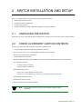
2
Switch Installation and Setup . . . . . . . . . . . . . . . . . . . . . . . . . . . . . . . . . . . . 2-1
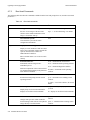
2.1
Unpacking The Switch . . . . . . . . . . . . . . . . . . . . . . . . . . . . . . . . . . . . . . . . . . . . . . . . . . . . . . . . . . . . . 2-1
2.2
Check Accessory Carton Contents . . . . . . . . . . . . . . . . . . . . . . . . . . . . . . . . . . . . . . . . . . . . . . . . . . . . 2-1
2.3
2.3.1
Inspecting the Switch . . . . . . . . . . . . . . . . . . . . . . . . . . . . . . . . . . . . . . . . . . . . . . . . . . . . . . . . . . . . . . 2-2
DS3 and E3 I/O Module Configuration . . . . . . . . . . . . . . . . . . . . . . . . . . . . . . . . . . . . . . . . . . . . . 2-4
2.4
2.4.1
2.4.2
2.4.3
Installing the Switch . . . . . . . . . . . . . . . . . . . . . . . . . . . . . . . . . . . . . . . . . . . . . . . . . . . . . . . . . . . . . . . 2-4
Desktop Installation . . . . . . . . . . . . . . . . . . . . . . . . . . . . . . . . . . . . . . . . . . . . . . . . . . . . . . . . . . . . 2-4
Rack Installation for ZX-250 . . . . . . . . . . . . . . . . . . . . . . . . . . . . . . . . . . . . . . . . . . . . . . . . . . . . . 2-6
Rack Installation for ZX-250r . . . . . . . . . . . . . . . . . . . . . . . . . . . . . . . . . . . . . . . . . . . . . . . . . . . . 2-8
2.5
Switch Configuration . . . . . . . . . . . . . . . . . . . . . . . . . . . . . . . . . . . . . . . . . . . . . . . . . . . . . . . . . . . . . 2-11
2.6
2.6.1
2.6.2
2.6.3
2.6.4
2.6.5
Using the Console . . . . . . . . . . . . . . . . . . . . . . . . . . . . . . . . . . . . . . . . . . . . . . . . . . . . . . . . . . . . . . . . 2-13
Console Commands . . . . . . . . . . . . . . . . . . . . . . . . . . . . . . . . . . . . . . . . . . . . . . . . . . . . . . . . . . . 2-13
Console Time-out. . . . . . . . . . . . . . . . . . . . . . . . . . . . . . . . . . . . . . . . . . . . . . . . . . . . . . . . . . . . . 2-15
Creating an Alias . . . . . . . . . . . . . . . . . . . . . . . . . . . . . . . . . . . . . . . . . . . . . . . . . . . . . . . . . . . . . 2-15
Ambiguous Commands . . . . . . . . . . . . . . . . . . . . . . . . . . . . . . . . . . . . . . . . . . . . . . . . . . . . . . . . 2-16
Console Help . . . . . . . . . . . . . . . . . . . . . . . . . . . . . . . . . . . . . . . . . . . . . . . . . . . . . . . . . . . . . . . . 2-16
2.7
2.7.1
2.7.2
2.7.3
SmartSwitch ATM Administrator . . . . . . . . . . . . . . . . . . . . . . . . . . . . . . . . . . . . . . . . . . . . . . . . . . . . 2-17
Installation Steps . . . . . . . . . . . . . . . . . . . . . . . . . . . . . . . . . . . . . . . . . . . . . . . . . . . . . . . . . . . . . 2-18
Starting SmartSwitch ATM Administrator the First Time . . . . . . . . . . . . . . . . . . . . . . . . . . . . . 2-19
Accessing Online Help. . . . . . . . . . . . . . . . . . . . . . . . . . . . . . . . . . . . . . . . . . . . . . . . . . . . . . . . . 2-20
3
IP Over ATM and LANE . . . . . . . . . . . . . . . . . . . . . . . . . . . . . . . . . . . . . . . . 3-1
3.1
3.1.1
Creating an IP over ATM VLAN . . . . . . . . . . . . . . . . . . . . . . . . . . . . . . . . . . . . . . . . . . . . . . . . . . . . . 3-1
ATM Addressing for IP over ATM . . . . . . . . . . . . . . . . . . . . . . . . . . . . . . . . . . . . . . . . . . . . . . . . 3-3
3.2
3.2.1
3.2.2
3.2.3
Creating an Emulated LAN. . . . . . . . . . . . . . . . . . . . . . . . . . . . . . . . . . . . . . . . . . . . . . . . . . . . . . . . . . 3-3
ATM Addressing for LAN Emulation . . . . . . . . . . . . . . . . . . . . . . . . . . . . . . . . . . . . . . . . . . . . . . 3-6
ELANs Across Multiple Switches . . . . . . . . . . . . . . . . . . . . . . . . . . . . . . . . . . . . . . . . . . . . . . . . . 3-6
Switch Clients . . . . . . . . . . . . . . . . . . . . . . . . . . . . . . . . . . . . . . . . . . . . . . . . . . . . . . . . . . . . . . . . 3-7
4
Switch Administration . . . . . . . . . . . . . . . . . . . . . . . . . . . . . . . . . . . . . . . . . . 4-1
4.1
Backing Up and Restoring Switch Configurations . . . . . . . . . . . . . . . . . . . . . . . . . . . . . . . . . . . . . . . . 4-1
4.2
4.2.1
4.2.2
4.2.3
ATM Routing . . . . . . . . . . . . . . . . . . . . . . . . . . . . . . . . . . . . . . . . . . . . . . . . . . . . . . . . . . . . . . . . . . . . 4-2
Creating an IISP Route . . . . . . . . . . . . . . . . . . . . . . . . . . . . . . . . . . . . . . . . . . . . . . . . . . . . . . . . . 4-2
UNI Routes . . . . . . . . . . . . . . . . . . . . . . . . . . . . . . . . . . . . . . . . . . . . . . . . . . . . . . . . . . . . . . . . . . 4-5
Route Metrics. . . . . . . . . . . . . . . . . . . . . . . . . . . . . . . . . . . . . . . . . . . . . . . . . . . . . . . . . . . . . . . . . 4-6
4.3
IP Routing . . . . . . . . . . . . . . . . . . . . . . . . . . . . . . . . . . . . . . . . . . . . . . . . . . . . . . . . . . . . . . . . . . . . . . . 4-7
4.4
Events and Alarms . . . . . . . . . . . . . . . . . . . . . . . . . . . . . . . . . . . . . . . . . . . . . . . . . . . . . . . . . . . . . . . . 4-9
SmartCell ZX-250 User Guide ix
Table of Contents
4.4.1
4.4.2
4.4.3
Event Categories. . . . . . . . . . . . . . . . . . . . . . . . . . . . . . . . . . . . . . . . . . . . . . . . . . . . . . . . . . . . . . . 4-9
Viewing Events and Alarms. . . . . . . . . . . . . . . . . . . . . . . . . . . . . . . . . . . . . . . . . . . . . . . . . . . . . 4-10
Deleting Events and Alarms. . . . . . . . . . . . . . . . . . . . . . . . . . . . . . . . . . . . . . . . . . . . . . . . . . . . . 4-11
4.5
4.5.1
4.5.2
4.5.3
4.5.4
PVC Connections . . . . . . . . . . . . . . . . . . . . . . . . . . . . . . . . . . . . . . . . . . . . . . . . . . . . . . . . . . . . . . . . 4-11
Point-to-Point PVCs . . . . . . . . . . . . . . . . . . . . . . . . . . . . . . . . . . . . . . . . . . . . . . . . . . . . . . . . . . . 4-12
Point-to-Multipoint PVCs . . . . . . . . . . . . . . . . . . . . . . . . . . . . . . . . . . . . . . . . . . . . . . . . . . . . . . 4-12
Connecting to Local Switch Client Through a PVC . . . . . . . . . . . . . . . . . . . . . . . . . . . . . . . . . . 4-14
Non-zero VPIs . . . . . . . . . . . . . . . . . . . . . . . . . . . . . . . . . . . . . . . . . . . . . . . . . . . . . . . . . . . . . . . 4-14
4.6
4.6.1
4.6.2
4.6.3
Traffic Management . . . . . . . . . . . . . . . . . . . . . . . . . . . . . . . . . . . . . . . . . . . . . . . . . . . . . . . . . . . . . . 4-17
Traffic Descriptors . . . . . . . . . . . . . . . . . . . . . . . . . . . . . . . . . . . . . . . . . . . . . . . . . . . . . . . . . . . . 4-17
Call Admission Control Policy. . . . . . . . . . . . . . . . . . . . . . . . . . . . . . . . . . . . . . . . . . . . . . . . . . . 4-19
EFCI, EPD, and RM Thresholds . . . . . . . . . . . . . . . . . . . . . . . . . . . . . . . . . . . . . . . . . . . . . . . . . 4-22
4.7
4.7.1
4.7.2
4.7.3
4.7.4
4.7.5
4.7.6
Upgrading and Changing Software . . . . . . . . . . . . . . . . . . . . . . . . . . . . . . . . . . . . . . . . . . . . . . . . . . . 4-23
Accessing the Boot Load Prompt . . . . . . . . . . . . . . . . . . . . . . . . . . . . . . . . . . . . . . . . . . . . . . . . . 4-23
Boot Load Commands . . . . . . . . . . . . . . . . . . . . . . . . . . . . . . . . . . . . . . . . . . . . . . . . . . . . . . . . . 4-24
Upgrading Boot Load Software . . . . . . . . . . . . . . . . . . . . . . . . . . . . . . . . . . . . . . . . . . . . . . . . . . 4-25
Upgrading POST Diagnostic Software . . . . . . . . . . . . . . . . . . . . . . . . . . . . . . . . . . . . . . . . . . . . 4-27
Upgrading Switch Operating Software . . . . . . . . . . . . . . . . . . . . . . . . . . . . . . . . . . . . . . . . . . . . 4-28
Using the Update Firmware Command . . . . . . . . . . . . . . . . . . . . . . . . . . . . . . . . . . . . . . . . . . . . 4-29
4.8
Saving Core Dumps. . . . . . . . . . . . . . . . . . . . . . . . . . . . . . . . . . . . . . . . . . . . . . . . . . . . . . . . . . . . . . . 4-30
4.9
4.9.1
4.9.2
4.9.3
4.9.4
4.9.5
4.9.6
4.9.7
4.9.8
4.9.9
4.9.10
4.9.11
4.9.12
4.9.13
4.9.14
4.9.15
Performing Hardware Maintenance. . . . . . . . . . . . . . . . . . . . . . . . . . . . . . . . . . . . . . . . . . . . . . . . . . . 4-32
Required Tools . . . . . . . . . . . . . . . . . . . . . . . . . . . . . . . . . . . . . . . . . . . . . . . . . . . . . . . . . . . . . . . 4-32
Internal Components . . . . . . . . . . . . . . . . . . . . . . . . . . . . . . . . . . . . . . . . . . . . . . . . . . . . . . . . . . 4-32
CPU Board . . . . . . . . . . . . . . . . . . . . . . . . . . . . . . . . . . . . . . . . . . . . . . . . . . . . . . . . . . . . . . . . . . 4-33
Main Switch Module . . . . . . . . . . . . . . . . . . . . . . . . . . . . . . . . . . . . . . . . . . . . . . . . . . . . . . . . . . 4-33
Extended Switch Module . . . . . . . . . . . . . . . . . . . . . . . . . . . . . . . . . . . . . . . . . . . . . . . . . . . . . . . 4-33
I/O Modules . . . . . . . . . . . . . . . . . . . . . . . . . . . . . . . . . . . . . . . . . . . . . . . . . . . . . . . . . . . . . . . . . 4-34
Removing a Switch Module . . . . . . . . . . . . . . . . . . . . . . . . . . . . . . . . . . . . . . . . . . . . . . . . . . . . . 4-34
Removing I/O Modules . . . . . . . . . . . . . . . . . . . . . . . . . . . . . . . . . . . . . . . . . . . . . . . . . . . . . . . . 4-36
Replacing a Switch Module . . . . . . . . . . . . . . . . . . . . . . . . . . . . . . . . . . . . . . . . . . . . . . . . . . . . . 4-37
Upgrading Main Switch Module (MSM-16 to MSM-32) . . . . . . . . . . . . . . . . . . . . . . . . . . . . . . 4-40
Adding an Expansion Switch Module . . . . . . . . . . . . . . . . . . . . . . . . . . . . . . . . . . . . . . . . . . . . . 4-40
Adding New I/O Modules . . . . . . . . . . . . . . . . . . . . . . . . . . . . . . . . . . . . . . . . . . . . . . . . . . . . . . 4-40
Adding a Power Supply Module (SmartCell ZX-250r Only) . . . . . . . . . . . . . . . . . . . . . . . . . . . 4-41
Removing a Power Supply Module (SmartCell ZX-250r Only) . . . . . . . . . . . . . . . . . . . . . . . . . 4-42
Replacing a Fuse. . . . . . . . . . . . . . . . . . . . . . . . . . . . . . . . . . . . . . . . . . . . . . . . . . . . . . . . . . . . . . 4-44
5
Troubleshooting . . . . . . . . . . . . . . . . . . . . . . . . . . . . . . . . . . . . . . . . . . . . . . 5-1
5.1
Troubleshooting IP over ATM . . . . . . . . . . . . . . . . . . . . . . . . . . . . . . . . . . . . . . . . . . . . . . . . . . . . . . . 5-1
5.2
Troubleshooting LAN Emulation . . . . . . . . . . . . . . . . . . . . . . . . . . . . . . . . . . . . . . . . . . . . . . . . . . . . . 5-2
5.3
Troubleshooting PNNI LinkS . . . . . . . . . . . . . . . . . . . . . . . . . . . . . . . . . . . . . . . . . . . . . . . . . . . . . . . . 5-3
5.4
5.4.1
5.4.2
5.4.3
Troubleshooting Congestion . . . . . . . . . . . . . . . . . . . . . . . . . . . . . . . . . . . . . . . . . . . . . . . . . . . . . . . . . 5-3
Diagnosing Congestion . . . . . . . . . . . . . . . . . . . . . . . . . . . . . . . . . . . . . . . . . . . . . . . . . . . . . . . . . 5-4
Global Congestion . . . . . . . . . . . . . . . . . . . . . . . . . . . . . . . . . . . . . . . . . . . . . . . . . . . . . . . . . . . . . 5-4
Port Congestion . . . . . . . . . . . . . . . . . . . . . . . . . . . . . . . . . . . . . . . . . . . . . . . . . . . . . . . . . . . . . . . 5-5
A
Acronyms . . . . . . . . . . . . . . . . . . . . . . . . . . . . . . . . . . . . . . . . . . . . . . . . . . A-1
x
SmartCell ZX-250 User Guide
Table of Contents
B
Specifications . . . . . . . . . . . . . . . . . . . . . . . . . . . . . . . . . . . . . . . . . . . . . . . B-1
B.1
Front Panel . . . . . . . . . . . . . . . . . . . . . . . . . . . . . . . . . . . . . . . . . . . . . . . . . . . . . . . . . . . . . . . . . . . . . .B-1
B.2
ZX-250r Redundant Power Supply Module . . . . . . . . . . . . . . . . . . . . . . . . . . . . . . . . . . . . . . . . . . . . .B-2
B.3
Technical Specifications . . . . . . . . . . . . . . . . . . . . . . . . . . . . . . . . . . . . . . . . . . . . . . . . . . . . . . . . . . . .B-3
C
Agent Support . . . . . . . . . . . . . . . . . . . . . . . . . . . . . . . . . . . . . . . . . . . . . . . C-1
C.1
C.1.1
C.1.2
C.1.3
C.1.4
C.1.5
C.1.6
C.1.7
MIB, SMI, MIB Files and Internet MIB Hierarchy . . . . . . . . . . . . . . . . . . . . . . . . . . . . . . . . . . . . . . . C-1
ZeitNet Cabletron Proprietary MIBs . . . . . . . . . . . . . . . . . . . . . . . . . . . . . . . . . . . . . . . . . . . . . . .C-2
Relation Between Object Identifier and the Represented Value . . . . . . . . . . . . . . . . . . . . . . . . . .C-3
Supported Protocols . . . . . . . . . . . . . . . . . . . . . . . . . . . . . . . . . . . . . . . . . . . . . . . . . . . . . . . . . . . .C-4
Supported SMI Formats . . . . . . . . . . . . . . . . . . . . . . . . . . . . . . . . . . . . . . . . . . . . . . . . . . . . . . . . .C-4
Zeitnet Cabletron Proprietary MIB Groups . . . . . . . . . . . . . . . . . . . . . . . . . . . . . . . . . . . . . . . . . .C-4
SmartCell ZX-250 MIB Support . . . . . . . . . . . . . . . . . . . . . . . . . . . . . . . . . . . . . . . . . . . . . . . . . .C-5
MIB Exceptions . . . . . . . . . . . . . . . . . . . . . . . . . . . . . . . . . . . . . . . . . . . . . . . . . . . . . . . . . . . . . . .C-6
C.2
C.2.1
Managing the SmartCell ZX-250 . . . . . . . . . . . . . . . . . . . . . . . . . . . . . . . . . . . . . . . . . . . . . . . . . . . . .C-7
Console Commands that Affect the Agent . . . . . . . . . . . . . . . . . . . . . . . . . . . . . . . . . . . . . . . . . .C-7
D
Technical Support . . . . . . . . . . . . . . . . . . . . . . . . . . . . . . . . . . . . . . . . . . . . D-1
D.1
Introduction . . . . . . . . . . . . . . . . . . . . . . . . . . . . . . . . . . . . . . . . . . . . . . . . . . . . . . . . . . . . . . . . . . . . . .D-1
D.2
Telephone Assistance . . . . . . . . . . . . . . . . . . . . . . . . . . . . . . . . . . . . . . . . . . . . . . . . . . . . . . . . . . . . . .D-1
D.3
FAX Service . . . . . . . . . . . . . . . . . . . . . . . . . . . . . . . . . . . . . . . . . . . . . . . . . . . . . . . . . . . . . . . . . . . . .D-1
D.4
Electronic Services . . . . . . . . . . . . . . . . . . . . . . . . . . . . . . . . . . . . . . . . . . . . . . . . . . . . . . . . . . . . . . . .D-1
D.5
Placing A Support Call . . . . . . . . . . . . . . . . . . . . . . . . . . . . . . . . . . . . . . . . . . . . . . . . . . . . . . . . . . . . .D-1
D.6
Hardware Warranty . . . . . . . . . . . . . . . . . . . . . . . . . . . . . . . . . . . . . . . . . . . . . . . . . . . . . . . . . . . . . . . .D-2
D.7
Software Warranty . . . . . . . . . . . . . . . . . . . . . . . . . . . . . . . . . . . . . . . . . . . . . . . . . . . . . . . . . . . . . . . .D-2
D.8
Repair Services . . . . . . . . . . . . . . . . . . . . . . . . . . . . . . . . . . . . . . . . . . . . . . . . . . . . . . . . . . . . . . . . . . .D-2
Index. . . . . . . . . . . . . . . . . . . . . . . . . . . . . . . . . . . . . . . . . . . . . . . . . . . . . . . .I-1
SmartCell ZX-250 User Guide xi
Table of Contents
xii
SmartCell ZX-250 User Guide
LIST OF FIGURES
Figure 2-1
Front panel of a SmartCell ZX-250 ATM switch . . . . . . . . . . . . . . . . . . . . . . . . . . . . . . . . . . . . . . . . . 2-2
Figure 2-2
Rear view of ZX-250. . . . . . . . . . . . . . . . . . . . . . . . . . . . . . . . . . . . . . . . . . . . . . . . . . . . . . . . . . . . . . . 2-2
Figure 2-3
Rear view of ZX-250r with both power supply modules . . . . . . . . . . . . . . . . . . . . . . . . . . . . . . . . . . . 2-3
Figure 2-4
Airflow space for the ZX-250 in desktop environment . . . . . . . . . . . . . . . . . . . . . . . . . . . . . . . . . . . . 2-5
Figure 2-5
Attaching mounting brackets. . . . . . . . . . . . . . . . . . . . . . . . . . . . . . . . . . . . . . . . . . . . . . . . . . . . . . . . . 2-6
Figure 2-6
After brackets are attached, mount the switch in the rack. . . . . . . . . . . . . . . . . . . . . . . . . . . . . . . . . . . 2-7
Figure 2-7
Attaching mounting brackets. . . . . . . . . . . . . . . . . . . . . . . . . . . . . . . . . . . . . . . . . . . . . . . . . . . . . . . . . 2-9
Figure 2-8
After brackets are attached, mount the switch in the rack. . . . . . . . . . . . . . . . . . . . . . . . . . . . . . . . . . 2-10
Figure 2-9
ZX-250 console and network connections . . . . . . . . . . . . . . . . . . . . . . . . . . . . . . . . . . . . . . . . . . . . . 2-12
Figure 2-10 SmartSwitch ATM Administrator . . . . . . . . . . . . . . . . . . . . . . . . . . . . . . . . . . . . . . . . . . . . . . . . . . . . 2-18
Figure 4-1
IISP route across PNNI domain . . . . . . . . . . . . . . . . . . . . . . . . . . . . . . . . . . . . . . . . . . . . . . . . . . . . . . 4-4
Figure 4-2
Routes needed for a second IISP switch . . . . . . . . . . . . . . . . . . . . . . . . . . . . . . . . . . . . . . . . . . . . . . . . 4-4
Figure 4-3
IP routing through SW1for connectivity to the Ethernet network . . . . . . . . . . . . . . . . . . . . . . . . . . . . 4-9
Figure 4-4
Memory locations affected by the boot load commands. . . . . . . . . . . . . . . . . . . . . . . . . . . . . . . . . . . 4-25
Figure 4-5
Internal components of the SmartCell ZX-250 ATM switch . . . . . . . . . . . . . . . . . . . . . . . . . . . . . . . 4-34
Figure 4-6
Remove the bezel from the chassis base. . . . . . . . . . . . . . . . . . . . . . . . . . . . . . . . . . . . . . . . . . . . . . . 4-35
Figure 4-7
Extractor lever arm function . . . . . . . . . . . . . . . . . . . . . . . . . . . . . . . . . . . . . . . . . . . . . . . . . . . . . . . . 4-35
Figure 4-8
Removing a switch module from the lower switch module position . . . . . . . . . . . . . . . . . . . . . . . . . 4-36
Figure 4-9
I/O module (installation/removal). . . . . . . . . . . . . . . . . . . . . . . . . . . . . . . . . . . . . . . . . . . . . . . . . . . . 4-37
Figure 4-10 Line up module on the nylon card guides. . . . . . . . . . . . . . . . . . . . . . . . . . . . . . . . . . . . . . . . . . . . . . 4-38
Figure 4-11 Push seated card in with even pressure. . . . . . . . . . . . . . . . . . . . . . . . . . . . . . . . . . . . . . . . . . . . . . . . 4-39
Figure 4-12 Complete seating of card with lever arms. . . . . . . . . . . . . . . . . . . . . . . . . . . . . . . . . . . . . . . . . . . . . . 4-40
Figure 4-13 Rear view of a ZX-250r redundant power supply module . . . . . . . . . . . . . . . . . . . . . . . . . . . . . . . . . 4-41
Figure 4-14 Rear view of ZX-250r with single power supply module. . . . . . . . . . . . . . . . . . . . . . . . . . . . . . . . . . 4-42
Figure 4-15 Holding screw for power supply module . . . . . . . . . . . . . . . . . . . . . . . . . . . . . . . . . . . . . . . . . . . . . . 4-43
Figure 4-16 RPS module extraction and replacement . . . . . . . . . . . . . . . . . . . . . . . . . . . . . . . . . . . . . . . . . . . . . . 4-43
Figure 4-17 Pry out the fuse assembly.. . . . . . . . . . . . . . . . . . . . . . . . . . . . . . . . . . . . . . . . . . . . . . . . . . . . . . . . . . 4-44
Figure 4-18 Detail of fuse assembly. . . . . . . . . . . . . . . . . . . . . . . . . . . . . . . . . . . . . . . . . . . . . . . . . . . . . . . . . . . . 4-45
Figure B-1
Front panel of the SmartCell ZX-250 ATM switch . . . . . . . . . . . . . . . . . . . . . . . . . . . . . . . . . . . . . . .B-1
Figure B-2
ZX-250r power supply module . . . . . . . . . . . . . . . . . . . . . . . . . . . . . . . . . . . . . . . . . . . . . . . . . . . . . . .B-2
Figure C-1
Internet MIB hierarchy . . . . . . . . . . . . . . . . . . . . . . . . . . . . . . . . . . . . . . . . . . . . . . . . . . . . . . . . . . . . .C-2
Figure C-2
ZeitNet Private MIBs . . . . . . . . . . . . . . . . . . . . . . . . . . . . . . . . . . . . . . . . . . . . . . . . . . . . . . . . . . . . . .C-3
SmartCell ZX-250 User Guide xiii
List of Figures
Figure C-3
xiv
ZeitNet Cabletron ZX-250 MIB object identifier example . . . . . . . . . . . . . . . . . . . . . . . . . . . . . . . . . C-4
SmartCell ZX-250 User Guide
LIST OF TABLES
Table 2-1
I/O module ID numbers. . . . . . . . . . . . . . . . . . . . . . . . . . . . . . . . . . . . . . . . . . . . . . . . . . . . . . . . . . . . . 2-3
Table 2-2
DS3 and E3 Module settings. . . . . . . . . . . . . . . . . . . . . . . . . . . . . . . . . . . . . . . . . . . . . . . . . . . . . . . . . 2-4
Table 2-3
Default accounts and passwords . . . . . . . . . . . . . . . . . . . . . . . . . . . . . . . . . . . . . . . . . . . . . . . . . . . . . 2-19
Table 4-1
Values for VPI and VCI . . . . . . . . . . . . . . . . . . . . . . . . . . . . . . . . . . . . . . . . . . . . . . . . . . . . . . . . . . . 4-15
Table 4-2
Traffic descriptor type number explanation . . . . . . . . . . . . . . . . . . . . . . . . . . . . . . . . . . . . . . . . . . . . 4-18
Table 4-3
Settings for QoS queues . . . . . . . . . . . . . . . . . . . . . . . . . . . . . . . . . . . . . . . . . . . . . . . . . . . . . . . . . . . 4-22
Table 4-4
Boot load commands . . . . . . . . . . . . . . . . . . . . . . . . . . . . . . . . . . . . . . . . . . . . . . . . . . . . . . . . . . . . . 4-24
Table B-1
Front Panel LEDs . . . . . . . . . . . . . . . . . . . . . . . . . . . . . . . . . . . . . . . . . . . . . . . . . . . . . . . . . . . . . . . . .B-1
Table B-2
Power Supply Module Lamps . . . . . . . . . . . . . . . . . . . . . . . . . . . . . . . . . . . . . . . . . . . . . . . . . . . . . . . .B-3
Table B-3
Hardware Specifications . . . . . . . . . . . . . . . . . . . . . . . . . . . . . . . . . . . . . . . . . . . . . . . . . . . . . . . . . . . .B-3
Table B-4
Physical Specifications . . . . . . . . . . . . . . . . . . . . . . . . . . . . . . . . . . . . . . . . . . . . . . . . . . . . . . . . . . . . .B-4
Table B-5
Environmental Specifications . . . . . . . . . . . . . . . . . . . . . . . . . . . . . . . . . . . . . . . . . . . . . . . . . . . . . . . .B-4
Table B-6
Power Specifications . . . . . . . . . . . . . . . . . . . . . . . . . . . . . . . . . . . . . . . . . . . . . . . . . . . . . . . . . . . . . . .B-4
Table B-7
ATM Port Specifications. . . . . . . . . . . . . . . . . . . . . . . . . . . . . . . . . . . . . . . . . . . . . . . . . . . . . . . . . . . .B-5
Table B-8
Protocols Standards and Specifications. . . . . . . . . . . . . . . . . . . . . . . . . . . . . . . . . . . . . . . . . . . . . . . . .B-5
Table B-9
Management Standards and Specifications. . . . . . . . . . . . . . . . . . . . . . . . . . . . . . . . . . . . . . . . . . . . . .B-6
Table B-10 RJ-45 to DB-9 Adapter (PC Serial Port Adapter) . . . . . . . . . . . . . . . . . . . . . . . . . . . . . . . . . . . . . . . . .B-6
Table C-1
Zeitnet proprietary MIB groupings . . . . . . . . . . . . . . . . . . . . . . . . . . . . . . . . . . . . . . . . . . . . . . . . . . .C-4
SmartCell ZX-250 User Guide xv
List of Tables
xvi
SmartCell ZX-250 User Guide
1 INTRODUCTION
Welcome to the SmartCell ZX-250 User Guide. This manual will help you quickly and easily install, configure, and
manage your SmartCell ZX-250 ATM switch.
By performing the steps described in chapters two and three of this manual, your switch will be physically installed,
accessible on your Ethernet network, and running either an IP over ATM VLAN or an emulated Ethernet LAN. Chapter
four explains procedures for switch use and maintenance. Chapter five shows you how to troubleshoot VLANs,
ELANs, and traffic management problems.
2p›F
4œÀÊ`iÍ>ˆ•i`Ê`iÃVÀˆ«Íˆœ˜ÃÊœvÊ.“>ÀÍ+i••Ê=9†ÔxäÊVœ˜Ãœ•iÊVœ““>˜`ÃÊ>˜`ÊÍ…iˆÀÊÖÃi]ÊÃiiÊ
Í…iÊ.“>ÀÍ+i••ÊÈ"äääÉ=9†ÔxäÊ-iviÀi˜ViÊ >˜Ö>•°
SmartCell ZX-250 User Guide 1-1
Introduction
1-2 SmartCell ZX-250 User Guide
2 SWITCH INSTALLATION AND SETUP
After you read this chapter, you will be able to perform the following tasks:
U
U
U
U
Initial installation of the switch
Complete the initial configuration
Use the console interface
Install the SmartSwitch ATM Administrator graphical management software
2.1
UNPACKING THE SWITCH
Remove the accessory carton from the ZX-250 shipping box. Carefully remove the switch from its packing material.
2.2
CHECK ACCESSORY CARTON CONTENTS
Open the accessory carton and check that it contains the following items:
— 7-foot UTP cable terminated on both ends with RJ-45 connectors
— 6-foot AC power cord (1 or 2 cords depending on switch model and options)
— RJ-45 to 9-pin female adapter (labeled PC)
— Console cabling instruction sheet
— Diskettes containing switch software, MIB files, SmartCell ATM Administrator software, and release notes
— Two rack-mount brackets
— two-hole brackets for ZX-250
— four-hole brackets for ZX-250r
— Rack mount bracket screws
— four #8-32 x 0.38 flat head screws for ZX-250
— four #8-32 x 0.38 flat head screws, four #6-32 x 0.38 flat head screws for ZX-250r
— SmartCell ZX-250 Release Notes
— SmartCell ZX-250 User Guide
— SmartCell 6A000/ZX-250 Reference Manual
2p›F
If any of these items are missing, contact Cabletron customer support
immediately.
SmartCell ZX-250 User Guide 2-1
Inspecting the Switch
2.3
Switch Installation and Setup
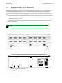
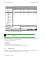
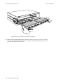
INSPECTING THE SWITCH
Depending on the configuration ordered, your switch looks similar to the drawing in Figure 2-1. You may have fewer
I/O modules than displayed in the drawing, in which case the missing modules are replaced by metal blanks.
Inspect the switch and make certain that its configuration corresponds to what was ordered. Check the following:
— Correct model number on the SmartCell ZX-250 switch sticker. On the ZX-250, the sticker is on the back. On
the ZX-250r, the sticker is on the bottom.
— Voltage rating on the power sticker.
— Input/Output (I/O) modules are of the correct type and quantity. Check the ID numbers on the I/O module
faceplates (see Table 2-1).
2p›F
All Single-Mode fiber connectors on I/O modules are blue.
Figure 2-1 Front panel of a SmartCell ZX-250 ATM switch
SP
ZX-250
THIS DEVICE COMPLIES WITH PART 15 OF THE FCC RULES.
OPERATION IS SUBJECT TO THE FOLLOWING TWO CONDITIONS:
(1) THIS DEVICE MAY NOT CAUSE HARMFUL INTERFERENCE, AND
(2) THIS DEVICE MUST ACCEPT ANY INTERFERENCE RECEIVED,
INCLUDING INTERFERENCE THAT MAY CAUSE UNDESIRED OPERATION.
LISTED
C
R
R
16EO
ITE MULTIPORT
SWITCH UNIT
CAUTION: FOR CONTINUED PROTECTION AGAINST RISK OF
FIRE, REPLACE ONLY WITH SAME TYPE AND RATING OF FUSE.
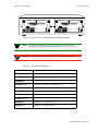
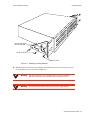
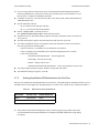
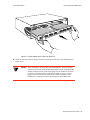
Figure 2-2 Rear view of ZX-250
2-2 SmartCell ZX-250 User Guide
id
FUSE:
4A, 250V
SN
LINE:
115V ~ 2.6A
60/50 Hz
NET.
ADD.
Switch Installation and Setup
Inspecting the Switch
CAUTION: For
continued protection
against risk of fire,
replace only with same
type and rating of fuse.
CAUTION: For
continued protection
against risk of fire,
replace only with same
type and rating of fuse.
Line:
100 - 125V ~ 3.2A
200 - 240V ~ 1.6A
50/60 Hz
AC Power OK
DC Power OK
Line:
100 - 125V ~ 3.2A
200 - 240V ~ 1.6A
50/60 Hz
AC Power OK
DC Power OK
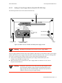
Figure 2-3 Rear view of ZX-250r with both power supply modules
2p›F
The ZX-250r (redundant power supply model) performs power sensing,
automatically configuring itself for the applied line voltage (115V or 230V).
>"•mamV
NEVER pick up the SmartCell ZX-250r by its power supply handles.
Table 2-1
I/O module ID numbers
Face Plate Number
Physical specifications
ZX-IOM-21-4
155 Mbps OC-3/STM-1, MMF/SC (4 port)
ZX-IOM-22-4
155 Mbps STS-3c/STM-1, UTP-5/RJ-45 (4port)
ZX-IOM-29-4
155 Mbps OC-3/STM-1, SMF-IR/SC (1port) MMF/SC (3 port)
ZX-IOM-29-4-IR
155 Mbps OC-3/STM-1, SMF-IR/SC (4 port)
ZX-IOM-29-4-LR
155 Mbps OC-3/STS-1, SMF-LR/SC (4 port)
ZX-IOM-31-1
622 Mbps OC-12/STM-4, MMF/SC (1 port)
ZX-IOM-39-1
622 Mbps OC-12/STM-4, SMF-IR/SC (1 port)
ZX-IOM-39-1-LR
622 Mbps OC-12/STM-4, SMF-LR/SC (1 port)
ZX-IOM-67-4
45 Mbps DS-3, Coax/BNC (4 port)
ZX-IOM-77-4
34 Mbps E-3, Coax/BNC (4 port)
SmartCell ZX-250 User Guide 2-3
Installing the Switch
Switch Installation and Setup
If the switch’s hardware or software configuration is incorrect, contact Cabletron customer support immediately.
2.3.1
DS3 and E3 I/O Module Configuration
Table 2-2 shows the pre-configured values for both the DS3 (ZX-IOM-67-4) and E3 (ZX-IOM-77-4) I/O modules.
These values cannot be changed. Accordingly, configure the connecting device’s interface to use these values.
Table 2-2
DS3 and E3 Module settings
Protocol
Mode
Framing
Empty Cell
Timing
Scrambling
Length
DS3
plcp
cbit
unassigned
internal
off
greater than 225 ft.
E3
plcp
G.751
unassigned
internal
off
N/A
2.4
INSTALLING THE SWITCH
SmartCell ZX-250 switches are designed to operate either while sitting on a desktop on their rubber feet or while
mounted in a rack by side-panel mounting brackets.
2.4.1
Desktop Installation
ZX-250 switches can be installed on any clean, dry, stable surface (desktop) that allows for at least four inches of clear
space on both sides of the switch:
U
U
ZX-250 — 17.5 inches wide by 14.5 inches deep
ZX-250r — 17.5 inches wide by 20.5 inches deep
2p›F
Because the ZX-250r power supply modules install from the back of the switch,
you may want to select a surface that provides sufficient room to remove and
install the power supply modules.
2-4 SmartCell ZX-250 User Guide
Switch Installation and Setup
Installing the Switch
Airflow
4 in.
Minimum
Clearance
for Airflow
4 Inches
Minimum
Clearance
for Airflow
Figure 2-4 Airflow space for the ZX-250 in desktop environment
s• Place the switch on the desktop so that it rests on its rubber feet. Do not place other objects closer
than four inches from the sides of the switch. This clear space must be maintained to insure proper
air flow.
%"¤›apm
Do not place the ZX-250 switch on its side. Doing so will impede airflow,
resulting in equipment overheating and eventual loss of operation or component
damage.
¢• Check the power label on the back of the switch to make sure that the required line voltage
corresponds to the line voltage you are using.
2p›F
The ZX-250r (redundant power supply model) performs power sensing,
automatically configuring itself for the applied line voltage (115V or 230V).
•• Insert the supplied power cord into the 3-prong power plug receptacle on the back of the switch.
T• +•Ö}ÊÍ…iÊ«œÝiÀÊVœÀ`ʈ˜ÍœÊ>˜Ê"+ÊœÖÍ•iÍÊÍ…>ÍÊ>VVi«ÍÃÊφ«Àœ˜}Ê«•Ö}ð
SmartCell ZX-250 User Guide 2-5
Installing the Switch
%"¤›apm
2p›F
Switch Installation and Setup
The SmartCell ZX-250 switch must be attached to a grounded 3-prong outlet.
Ensure that the outlet has a proper safety ground. Do not defeat the safety
ground by using a 2-prong adapter or extension cord. Doing so voids the new
product warranty.
For information on power consumption, see Appendix B, “Specifications.”
This desktop installation is complete. Proceed to the “Switch Configuration” section.
2.4.2
Rack Installation for ZX-250
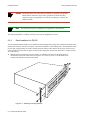
You can install the SmartCell ZX-250 in a standard 19-inch mounting rack by using the provided side-mount brackets.
Each switch occupies 4.5 inches of rack space or between two and three “rack mounting units.” This installation results
in an air gap of approximately 0.5 inches vertically between switches. There must be an air gap of at least four (4)
inches on either side of the rack for proper air flow to the cooling fans. (the ZX-250 chassis are 17.5 inches wide by
14.5 inches deep.)
s• With the ZX-250 switch resting on a flat surface, use a Phillips screwdriver to mount the brackets
on both sides of the front of the switch (see Figure 2-5). Use two (2) #8-32 x 0.38 flat-head screws
to attach each bracket to the side of the chassis.
Figure 2-5 Attaching mounting brackets.
2-6 SmartCell ZX-250 User Guide
Switch Installation and Setup
Installing the Switch
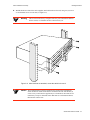
¢• With the brackets in front of the rack’s uprights, attach the brackets to the rack, using two (2) #10-32
x 0.50 flat-head screws on each side (see Figure 2-6).
>"•mamV
The ZX-250 switch is heavy enough to make one-person installation difficult.
For this reason, it is advisable to have someone assist you.
Figure 2-6 After brackets are attached, mount the switch in the rack.
%"¤›apm
The mounting brackets must be attached to the switch before mounting the
switch on the rack. Each switch must be mounted to the rack with all four (4)
screws. Every switch must be supported by its own brackets. DO NOT stack a
unit directly on top of a mounted switch. DO NOT use rack-mounted shelves
that interfere with air flow.
SmartCell ZX-250 User Guide 2-7
Installing the Switch
Switch Installation and Setup
•• Check the power label on the back of the switch to make sure that the required line voltage
corresponds to the line voltage you are using.
T• Insert the supplied power cord into the 3-prong power receptacle on the back of the switch.
Q• +•Ö}ÊÍ…iÊ«œÝiÀÊVœÀ`ʈ˜ÍœÊ>Ê>˜Ê"+ÊœÖÍ•iÍÊÍ…>ÍÊ>VVi«ÍÃÊφ«Àœ˜}Ê«•Ö}ð
%"¤›apm
2p›F
The SmartCell ZX-250 switch must be attached to a grounded 3-prong outlet.
Ensure that the outlet has a proper safety ground. Do not defeat the safety
ground by using a 2-prong adapter or extension cord. Doing so voids the new
product warranty.
For information on power consumption, see Appendix B, “Specifications.”
Rack installation is complete. Proceed to the section: “Switch Configuration.”
2.4.3
Rack Installation for ZX-250r
You can install the SmartCell ZX-250r switch in a standard 19-inch mounting rack by using the provided side-mount
brackets. Each switch occupies 4.5 inches of rack space or between two and three “rack mounting units.” This
installation results in an air gap of approximately 0.5 inches vertically between switches. There must be an air gap of
at least four (4) inches on either side of the rack for proper air flow to the cooling fans. (ZX-250r chassis are 17.5 inches
wide by 20.5 inches deep.)
>"•mamV
If you perform the following procedure with the SmartCell ZX-250r power
supplies installed, make certain that the they are locked in place.
NEVER lift or move the SmartCell ZX-250r by its power supply handles.
s• With the SmartCell ZX-250r switch resting on a flat surface, use a Phillips screwdriver to remove
two (2) #6-32 screws from each side of the switch chassis (see Figure 2-7). These screws are
replaced by screws included with the SmartCell ZX-250r rack mount components.
¢• Mount the brackets on both sides of the front of the switch (see Figure 2-7). Attach each bracket to
the side of the chassis using two (2) #8-32 x 0.38 flat-head screws and two (2) #6-32 x 0.38 flat-head
screws.
2-8 SmartCell ZX-250 User Guide
Switch Installation and Setup
Installing the Switch
Remove two screws
on side of ZX-250
#6-32 X 0.38
#8-32 X 0.38
Figure 2-7 Attaching mounting brackets.
•• With the brackets in front of the rack’s uprights, attach the brackets to the rack, using two (2) #10-32
x 0.50 flat-head screws on each side (see Figure 2-8).
>"•mamV
The ZX-250r switch is heavy enough to make one-person installation
difficult. For this reason, it is advisable to have someone assist you.
>"•mamV
Do not pick up the SmartCell ZX-250r by its power supply handles.
SmartCell ZX-250 User Guide 2-9
Installing the Switch
Switch Installation and Setup
Figure 2-8 After brackets are attached, mount the switch in the rack.
%"¤›apm
The mounting brackets must be attached to the switch before mounting the
switch on the rack. Each switch must be mounted to the rack with all four (4)
screws. Every switch must be supported by its own brackets. DO NOT stack a
unit directly on top of a mounted switch. DO NOT use rack-mounted shelves
that interfere with air flow.
T• Insert the supplied power cord into the 3-prong power receptacle on the back of the switch.
Q• +•Ö}ÊÍ…iÊ«œÝiÀÊVœÀ`ʈ˜ÍœÊ>Ê>˜Ê"+ÊœÖÍ•iÍÊÍ…>ÍÊ>VVi«ÍÃÊφ«Àœ˜}Ê«•Ö}ð
%"¤›apm
The SmartCell ZX-250r switch must be attached to a grounded 3-prong outlet.
Ensure that the outlet has a proper safety ground. Do not defeat the safety
ground by using a 2-prong adapter or extension cord. Doing so voids the new
product warranty.
2-10 SmartCell ZX-250 User Guide
Switch Installation and Setup
2p›F
Switch Configuration
For information on power consumption, see Appendix B, “Specifications.”
Rack installation for the ZX-250r is complete. Proceed to the next section: “Switch Configuration.”
2.5
SWITCH CONFIGURATION
Initial configuration of your ZX-250 switch consists of setting the name, Ethernet IP address, and subnet mask. Once
this is done, the switch can be reached for additional configuration and administration through your Ethernet network.
Perform the following steps to configure initial switch parameters:
s• Configure a dumb terminals or PCs running emulation software to use the following communication
parameters:
†
†
†
†
†
Baud rate = 9600
Data bits = 8
Stop bits = 1
Parity = none
Flow Control = none
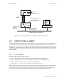
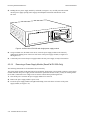
¢• Plug one end of the supplied RJ-45 UTP cable into the 9-pin COM port RJ-45 adapter.
2p›F
For information about adapter wiring configurations, see Appendix B,
“Specifications.”
Plug the other end of the UTP cable into the ZX-250 female RJ-45 jack labeled Terminal, located at the bottom
center of the switch’s front panel (see Figure 2-9).
•• Connect the switch to your network by plugging a UTP cable into the ZX-250 female RJ-45 jack
labeled Ethernet, located at the lower right of the switch’s front panel (see Figure 2-9).
SmartCell ZX-250 User Guide 2-11
Switch Configuration
Switch Installation and Setup
1
C
NO SYNC
NO SYNC
DATA
DATA
1
D
2
3
4
1
NO SYNC
A
2
3
4
2
3
4
NO SYNC
B
DATA
MON
DATA
DIAG
TEST
RESET
FAIL
STATUS
POWER
TERMINAL
ZX-250
Terminal
RJ-45
Port
RX DATA
ETHERNET
TX DATA
Ethernet
RJ-45
Port
Ethernet
Hub
Terminal
Figure 2-9 ZX-250 console and network connections
T• Start the dumb terminal or PC and its terminal emulation software; then turn on the ZX-250 switch.
Q• As the SmartCell ZX-250 powers up, a series of diagnostic messages appears on the terminal’s
screen.
–• After the diagnostics are finished, the switch prompts for a password. Enter the default password,
“admin.”
•• 0…iÊÃ݈ÍV…Ê«Àœ“«ÍÃÊvœÀÊÍ…iʈ˜vœÀ“>͈œ˜Ê˜iViÃÃ>ÀßÊ͜ʓ>ŽiÊÍ…iÊÃ݈ÍV…Ê>VViÃÈL•iÊÍ…ÀœÖ}…ÊßœÖÀÊ.Í…iÀ˜iÍÊ
˜iÍÝœÀŽ°
U
U
U
Switch name
IP address
Subnet mask
Once you enter these parameters and reboot the switch, you can log off the local console connection. You can perform
all additional configuration over your network using a telnet connection.
2p›F
Only one console connection is allowed at any time. To reach the SmartCell
ZX-250 through telnet, you must exit the local terminal connection by entering the
exit command.
2-12 SmartCell ZX-250 User Guide
Switch Installation and Setup
Using the Console
The following is an example of the initial configuration session:
SmartCell ZX Version 2.1 (c) Cabletron Inc.
< “admin” is the default password
password:: admin
The current user is Administrator
Could not find setup file
Running Setup Automatically
< a switch name
SwitchName() : My_ZX250
< an IP address
IPAddress(0.0.0.0) : 210.160.77.254
< a subnet mask
IPNetMask(255.0.0.0) : 255.255.255.0
Confirm(y/n)?:y
Changing IP Address on System. Telnet session (if any) will be lost.
SmartCell ZX #
Before continuing to chapter 3, “IP over ATM and LANE,” read the following sections for information about
U
U
Using the SmartCell X-250 console
Installing and getting started with the Windows-based SmartSwitch ATM Administrator application
2.6
USING THE CONSOLE
Use the ZX-250 console interface to configure and manage your switch. The following is a description of the console
interface and its operation.
2.6.1
Console Commands
2p›F
For detailed descriptions of console commands, see the SmartCell 6A000/ZX-250
Reference Manual.
All console commands use the syntax:
operator switch-attribute [<parameter 1> <parameter 2>... <parameter n>]
Where the operator is one of the following:
show
add
( display): Show the current values used by a switch-attribute.
( create): Add a new instance of a switch-attribute.
delete
( remove): Delete an instance of a switch-attribute.
modify
( set): Change the values that currently define a switch-attribute.
start:
Start a process on the switch; for example, start the LAN Emulation Configuration Server.
restart:
Restart a process on the switch; for example, restart a client.
flush:
Remove assigned values; for example, flush a route table.
alias:
Create easier names for often-used commands and their parameters.
SmartCell ZX-250 User Guide 2-13
Using the Console
Switch Installation and Setup
Entering parameters at the command line is optional. If a command requires parameter values, it prompts you for them.
For instance, in the example below, show is the operator, portconfig is the switch-attribute, and a1 is the parameter
indicating that you want to show configuration information about port A1.
SmartCell ZX # show portconfig a1
==================================================
Port: A1
-------------------------------------------------Parameter
Configured
Current
-------------------------------------------------Sig Type
autoConfig
pnni10
Sig Role
other
symmetric
Interface Type
private
private
Max vpi bits
0
0
Max vci bits
12
12
Max SVC vpci
0
0
Min SVC vci
32
32
Max Vccs
4096
4096
-------------------------------------------------Other parameters
-------------------------------------------------Port Admin Status
UP
Ilmi Admin Status
Enabled AddressRegistration Connectivity
Oper State
UP
Trans Type
STS-3c
Media Type
MMF (S)
Bandwidth
155 MB
SmartCell ZX #
If you don’t specify parameters with the command, the console prompts you for an input value and provides a default
value displayed in parenthesis. For example, if you enter show portconfig without specifying a port (as a parameter),
the following appears. Here, the default of “all” ports is presented. You can either accept the default by pressing Enter,
or you can enter a specific port number. Taking the default displays the following:
SmartCell ZX # show portconfig
PortNumber(ALL)
:
Port
Intf
Sig
Trans
Media
Speed
Oper
ID
Type
Type
Type
Type
(MB/s)
State
==============================================================================
A1
private
pnni10
STS-3c MMF (S)
155 MB
UP
A2
private
autoConfig
STS-3c MMF (S)
155 MB
DOWN
A3
private
autoConfig
STS-3c MMF (S)
155 MB
DOWN
A4
private
autoConfig
STS-3c MMF (S)
155 MB
DOWN
B1
private
autoConfig
STS-3c MMF (S)
155 MB
DOWN
B2
private
autoConfig
STS-3c MMF (S)
155 MB
DOWN
B3
private
autoConfig
STS-3c MMF (S)
155 MB
DOWN
B4(CPU) private
uni31
STS-3c MMF (S)
155 MB
UP
C1
private
autoConfig
STS-3c SMF (I)
155 MB
DOWN
C2
private
autoConfig
STS-3c MMF (S)
155 MB
DOWN
C3
private
autoConfig
STS-3c MMF (S)
155 MB
DOWN
C4
private
autoConfig
STS-3c MMF (S)
155 MB
DOWN
D1
private
autoConfig
STS-3c CAT5 UTP 155 MB
DOWN
D2
private
autoConfig
STS-3c CAT5 UTP 155 MB
DOWN
D3
private
autoConfig
STS-3c CAT5 UTP 155 MB
DOWN
D4
private
autoConfig
STS-3c CAT5 UTP 155 MB
DOWN
SmartCell ZX #
2p›F
When you accept the (all) default for show, the information displayed is often
abridged.
2-14 SmartCell ZX-250 User Guide
Switch Installation and Setup
2.6.2
Using the Console
Console Time-out
The console can be configured to exit if it does not sense a key stroke within a defined length of time. By default, the
SmartCell ZX-250 is set to never time-out (value = 0). To activate the time-out feature, use the set ConsoleTimeOut
command to adjust the time-out period:
SmartCell ZX # set consoletimeout
Timeout(0)
Confirm (y/N)? : y
SmartCell ZX #
2.6.3
Creating an Alias
Use the add
alias
: 30 <Will time-out in 30 minutes without input
command to create shorter or easier-to-remember names for command lines. For example:
SmartCell ZX # add alias
AliasName()
AliasedString()
SmartCell ZX #
: traffic
: set switchtrafficcongestion
The above example creates an alias (traffic) that you can enter in place of the command set
For example:
SwitchTrafficCongestion.
SmartCell ZX # traffic
Queue1EFCIThreshold(4096)
Queue2EFCIThreshold(4096)
Queue3EFCIThreshold(4096)
Queue4EFCIThreshold(4096)
LowEPDWatermark(10922)
HighEPDWatermark(21845)
RMCellMarkingEnable(1)
EFCIMarkingEnable(1)
SmartCell ZX #
Enter the show
:
:
:
:
:
:
:
:
alias command to display a list of all defined aliases and the command lines to which they correspond.
:SmartCell ZX # show alias
AliasName(ALL)
:
Alias List
==============================================================================
Index Alias Name
: Aliased Command
1
PING
: Start ping
2
xxx
: show portconfig
3
traffic
: set switchtrafficcongestion
SmartCell ZX #
SmartCell ZX-250 User Guide 2-15
Using the Console
2.6.4
Switch Installation and Setup
Ambiguous Commands
If you enter part of a command, and that part is not unique, the console displays a numbered list of possible matching
commands. For example, entering show pnnin is ambiguous because there are several commands that start with
“pnnin.” In response, the SmartCell ZX-250 displays a list of the possible commands:
< “pnnin” is ambiguous
SmartCell ZX # show pnnin
Objects beginning with pnnin for action show
0 :
PnniNeighbor
1 :
PnniNetworkLink
2 :
PnniNetworkNode
3 :
PnniNode
4 :
PnniNodeTimer
< I meant PnniNode, so I enter number three (3) from the list
(#)Command (Q)uit? : 3
SmartCell ZX # show PnniNode
Selecting number three from the list automatically enters the corresponding command; pressing enter executes the
command:
PNNI Node Information
================================================================================
Level
: 80
Node Id
: 50:a0:39:00:00:00:00:00:00:00:00:00:28:c1:80:00:20:d4:28:c1:80:00
Lowest
: TRUE
Admin Status : UP
Oper Status : UP
Atm Address : 39:00:00:00:00:00:00:00:00:00:28:c1:80:00:20:d4:28:c1:80:00
Peer Group Id: 50:39:00:00:00:00:00:00:00:00:00:00:00:00
Rst Transit : FALSE
Rst Branching: FALSE
DB Overload : FALSE
Ptse
: 2
SmartCell ZX #
2.6.5
Console Help
The console provides several levels of help for console commands. For example, to list the switch attributes that can
be used with a particular operator, enter the word help (or ?) followed by the operator.
SmartCell ZX # help add
HELP ---add
==============================================================================
add
[ AlarmConfig | Alias | ATMRoute | BUSELAN | Community | ELAN |
Interface | IPATMClient | IPATMPVC | LANEClient | LECSELAN |
LECSELANLEC | LECSTLVSET | LESELAN | NetPrefix | PnniMetrics |
PnniSummaryAddress | PVC | Route | ServiceRegistry |
TrafficDescriptor | TrapCommunity ]
SmartCell ZX #
2-16 SmartCell ZX-250 User Guide
Switch Installation and Setup
SmartSwitch ATM Administrator
To obtain an explanation of a command and its parameters, enter the word help (or ?) before the command.
SmartCell ZX # ? add laneclient
Create LANE Client
============================================================================
ClientNumber
Local Client Number (0-127)
LanName
Name of the ELAN to join
ServerType
Type of LANE Server [LECS, LES]
ServerAddress
ATM Address of the LANE Server
IPAddress
IP Address of the Client
NetMask
IP Netmask of the Client
MTU
MTU for the Client [1516, 9234, NONE]
SmartCell ZX #
While entering a command, you can obtain help about the current parameter by entering a question mark (?) at the
prompt. For example:
SmartCell ZX # add atmroute
PortNumber(A1)
: a3
AtmAddress()
: 39:00:00:00:00:00:00:00:00:00:14:72:80
PrefixLength(104)
:
Index(0)
:
Type(Internal)
: ?
The type of reachability. Use Internal, Exterior, or Reject.
Type(Internal)
:exterior
Scope(0)
:
MetricsTag(0)
:
SmartCell ZX #
2p›F
2.7
Press the Esc key to back out of any command before you enter the last value.
SMARTSWITCH ATM ADMINISTRATOR
SmartSwitch ATM Administrator is a Windows application that manages SmartCell ATM switches. It supports the
following operations:
U
U
U
U
U
Switch management
Emulated Local Area Network (ELAN) management
Connection management
Alarm management
Switch discovery
Additionally, the SmartSwitch ATM Administrator provides the following capabilities that are not available from the
console interface:
U
U
U
U
Use a graphical user interface
Perform drag and drop operations
Manage all switches from one console
Perform transactions across multiple switches (for example, create an ELAN when the servers are
not co-located
SmartCell ZX-250 User Guide 2-17
SmartSwitch ATM Administrator
Switch Installation and Setup
Figure 2-10 SmartSwitch ATM Administrator
2p›F
Capabilities that are not available from the SmartSwitch ATM Administrator are
debugging and tracing.
SmartSwitch ATM Administrator can be installed on a PC running Windows NT 4.0, Windows NT 3.51, or Windows
95, and requires the following PC hardware configuration:
U
U
U
U
U
Pentium 133 Mhz or faster processor
20 MB disk space
32 MB RAM
Monitor with resolution of at least 800 x 600 pixels
Network connections (either Ethernet or ATM) to the switches you manage
2.7.1
Installation Steps
The installation process for SmartSwitch ATM Administrator is essentially the same for all the supported operating
systems. Follow these instructions for installation on NT 4.0, NT 3.5.1, or Win95.
2-18 SmartCell ZX-250 User Guide
Switch Installation and Setup
SmartSwitch ATM Administrator
s• If you are using diskettes, make backup copies of the SmartSwitch ATM Administrator diskettes.
Put the original diskettes in a safe place; use them if your backup copies become unusable. Use your
backup copies to complete the installation procedure.
¢• Load Disk 1 into drive a or note the network <path> to the directory that contains the SmartSwitch
ATM Administrator files.
•• Start the installation software:
†
†
NT 4.0 or Win95, click Start then click Run
NT 3.5.1, select the File menu and click Run
T• Enter a:\setup.exe to install from drive a:
OR <path>\Disk1\setup.exe to install from the network
Q• The Software License Agreement dialog box appears. Follow the instructions on the screen and click
Yes to proceed.
–• The Welcome dialog box appears. Read the instructions and click Next to proceed.
•• The Choose Destination Location screen appears. Follow the instructions on the screen and click
Next. Setup performs the following tasks:
†
†
†
Copies several files to c:\ZXAdmin or to the destination you specified
Creates a program group called SmartCell ZX Network Management Tools (Common)
Creates icons in the group:
SmartSwitch ATM Administrator – starts the application
Online Help – starts the on-line help
Readme – displays release notes
UnInstall SmartSwitch ATM Administrator – removes the application from your PC
G• The Setup Complete dialog box appears. Read the message and click Finish.
n• The Information dialog box appears. Click OK.
2.7.2
Starting SmartSwitch ATM Administrator the First Time
When you use SmartSwitch ATM Administrator for the first time, you should change the default passwords to prevent
unauthorized access to the application. The application arrives with two user accounts set up, as described in Table 2-3.
Table 2-3
Default accounts and passwords
User Name
Access Level
Default Password
admin
Administrator
admin
guest
Guest
guest
s• In the SmartCell ZX Network Management Tools (Common) program group, double click on the
icon labeled SmartSwitch ATM Administrator. The SmartSwitch ATM Administrator Login dialog
box appears.
SmartCell ZX-250 User Guide 2-19
SmartSwitch ATM Administrator
Switch Installation and Setup
¢• Enter the default user name, admin. The user name is case sensitive.
•• Enter the default password, admin, and click the OK button or press Enter. The password is case
sensitive.
T• The SmartSwitch ATM Administrator window appears. On the Applications menu, select User
Management.
2.7.3
Accessing Online Help
All SmartSwitch ATM Administrator operations (including changing passwords and adding users) are documented
within the application’s online help. Follow these instructions to access the on-line help facility.
s• From the Help menu, select SmartSwitch ATM Administrator Help Topics.
¢• The Help Topics dialog box appears. You have three options for viewing online help:
†
Click the Contents tab to show the Table of Contents of the online help. Click on the topic you
wish to read about.
†
†
Click the Index tab to select from an alphabetical list of help topics.
Click the Find tab to search for a particular topic.
2-20 SmartCell ZX-250 User Guide
3 IP OVER ATM AND LANE
This chapter describes working with the SmartCell ZX-250 IP over ATM VLAN and emulated LAN capabilities. At
the end of this chapter you will be able to use your SmartCell ZX-250 switch to
U
U
Create an IP over ATM VLAN
Create an emulated Ethernet LAN (LANE)
3.1
CREATING AN IP OVER ATM VLAN
This section describes implementing IP over ATM on your SmartCell ZX-250 switch. The following assumptions are
made:
U
U
U
The ZX-250 switch will have a client on the IP over ATM VLAN
The ARP server will reside on the switch and correspond to the address of the switch client
All end nodes (computers, edge devices, and so on) support Switched Virtual Circuits (SVCs)
s• Log into the switch, either through the terminal port or through the Ethernet interface by telnet.
¢• Create a client on the switch and assign it as the ARP server for the VLAN.
SmartCell ZX # add ipatmclient
ClientNumber(0) : 1
ServerType(NONE) : local < the ARP server is assigned to the switch client
ServerAddress() :
< IP address is for example only
IPAddress() : 90.1.1.1
< subnet mask is for example only
NetMask(255.0.0.0) : 255.255.255.0
MTU(9180) :
SmartCell ZX #
The example above creates a client on the switch, designates the client as the ARP server for the VLAN
(ServerType = local), and assigns the client an IP address and subnet mask.
2p›F
The command add ipatmclient always prompts you with a subnet mask that is
appropriate for the IP address. However, if necessary, you can change the subnet
mask to correspond to the strategy employed within your networks.
2p›F
Never create an IP over ATM VLAN (or an IP over ATM client) with the same
subnet as the SmartCell ZX-250 Ethernet port.
SmartCell ZX-250 User Guide 3-1
Creating an IP over ATM VLAN
IP Over ATM and LANE
•• Enter the show client command to make sure the client is operational and to obtain the 20-byte
ATM address of the ARP server. For instance, if you used the client number (client 1) from the
example in step 2, enter the following command.
SmartCell ZX # show client 1
IP/ATM Client 1
============================================================================
Client State
: Operational
Client Address
: 39:00:00:00:00:00:00:00:00:00:14:41:80:00:00:5A:01:01:01:00
Server
: is local
Server Connection : Established
MTU
: 9180
IP Address
: 90.1.1.1
IP NetMask
: 255.255.255.0
SmartCell ZX #
T• Physically connect your end nodes and edge devices to the ZX-250 ports.
2p›F
Your end nodes do not need to be physically attached to the switch that contains
the ARP server. For example, an end station is connected to a ZX-250 switch that
is connected through a route to the switch containing the ARP server . No special
configuration is needed for this end station to participate in the VLAN because the
end station automatically finds its path across the route to the ARP server and the
other VLAN members.
Q• Configure the ATM interface or adapter for end nodes and edge devices. Typically, configuration
consists of designating IP over ATM as the protocol, assigning the device an IP address, and
specifying the 20-byte ATM address of the ARP server (the switch’s client address). For details on
the SmartCell ZX-250 automatic addressing scheme for IP over ATM, see Section 3.1.1.
–• As your end devices are configured and started, they register with the ARP server. You can test
whether your IP over ATM VLAN is functional by pinging from one end device to another.
To make certain that all end devices are registered with the ARP server, you can inspect the switch’s ARP table using
the show ipatmarp command. For example, if three end devices with IP addresses 90.1.1.2, 90.1.1.3, and 90.1.1.4 are
added to the VLAN, the following ARP table entries should exist:
SmartCell ZX # show ipatmarp
ClientNumber(ALL)
:
IP/ATM Server 1 ARP Table
IP Address
ATM Address
============================================================================
90.1.1.2 39:00:00:00:00:00:00:00:00:00:14:41:80:00:00:5A:01:01:02:00
IP/ATM Server 3 ARP Table
IP Address
ATM Address
============================================================================
90.1.1.3 39:00:00:00:00:00:00:00:00:00:14:41:80:00:00:5A:01:01:03:00
IP/ATM Server 5 ARP Table
IP Address
ATM Address
============================================================================
90.1.1.4 39:00:00:00:00:00:00:00:00:00:14:41:80:00:00:5A:01:01:04:00
SmartCell ZX #
3-2 SmartCell ZX-250 User Guide
IP Over ATM and LANE
2p›F
Creating an Emulated LAN
If configured devices fail to join the VLAN, see Chapter 4, Section 4.2.2, “UNI
Routes.” Also, see Chapter 5, Section 5.1, “Troubleshooting IP Over ATM.”
You have completed the process for creating an IP over ATM VLAN. Continue to the next section for instructions on
creating an emulated LAN or go to Chapter 4, “Switch Administration,” for information about SmartCell ZX-250
switch operations and maintenance.
3.1.1
ATM Addressing for IP over ATM
The SmartCell ZX-250 provides a default format for ATM addresses used by IP over ATM. The default format is
constructed as follows:
netprefix + two zero bytes + IP address of the device (in hex) + a trailing zero byte
Where the netprefix is constructed from
39 + nine zero bytes + the last three bytes of the device’s MAC address
For instance, if the switch’s MAC address is 00:20:D4:14:41:80 and the switch’s client IP address is 90.1.1.1, then
the 20-byte ATM address of the ARP server is
39:00:00:00:00:00:00:00:00:00:14:41:80:00:00:5A:01:01:01:00
Where
39:00:00:00:00:00:00:00:00:00:14:41:80 = netprefix
00:00 = two trailing zeros
5A:01:01:01 = IP address 90.1.1.1 in hexadecimal
00 = trailing zeros byte
3.2
CREATING AN EMULATED LAN
This section describes the steps for implementing an Ethernet Emulated LAN (ELAN) on your SmartCell ZX-250
switch. The following assumptions are made:
U
U
The SmartCell ZX-250 switch will contain a client on the ELAN.
U
All end nodes support Switched Virtual Circuits (SVCs).
All end nodes (computers, edge devices, other switches, and so on) support the Well Known LECS
Address or can obtain the address of the LECS using ILMI.
2p›F
An ELAN comes pre-configured on SmartCell ZX-250 switches. The ELAN
name is “ELAN000.” To use this ELAN, start the LECS, configure your end nodes
and edge devices to use this ELAN000, and then plug them into the SmartCell
ZX-250.
SmartCell ZX-250 User Guide 3-3
Creating an Emulated LAN
IP Over ATM and LANE
s• Enter the start LECS command to activate LANE server services on this switch.
SmartCell ZX # start lecs
NOTICE - 'LECS' ***** LECS started *****
SmartCell ZX #
¢• Create an ELAN on your SmartCell ZX-250 switch by executing the add elan command. The
following is an example.
SmartCell ZX # add elan
<1 is used instead of the default, (0)
ELANNumber(0) : 1
ELANName(ELAN001): Marketing <ELAN is named Marketing instead of the default, (ELAN000)
ConnectMethod(SVC):
<The default (Ethernet) is used
ELANType(802.3)
Multipoint(YES) :
MTU(1516) :
Distribute(PROXY) :
SmartCell ZX #
•• Create a client for the switch on the ELAN. For example, enter
SmartCell ZX # add laneclient
<One is used instead of the default, (0)
ClientNumber(0) :1
LanName(ELAN001) : Marketing < ELAN name is Marketing, not the default, (ELAN001)
ServerType(LECS) :
<No LANE server address is specified; see note below
ServerAddress()
IPAddress() : 90.1.1.1 < IP address and subnet mask are included only as examples
NetMask(255.0.0.0): 255.255.255.0
MTU(1516) :
SmartCell ZX #
2p›F
The command add laneclient always prompts you with a subnet mask that is
appropriate for the IP address. However, if necessary, you can change the subnet
mask to correspond to the strategy employed within your networks.
2p›F
When you create a client, it automatically finds the LECS address using ILMI.
As the local client joins the ELAN, the following messages are sent to the Event log:
NOTICE - 'ZLESSRV'
14:41:82:00
NOTICE - 'ZLESSRV'
14:41:82:00
%"¤›apm
LES Join 39:00:00:00:00:00:00:00:00:00:14:41:80:00:20:D4:
BUS Connect 39:00:00:00:00:00:00:00:00:00:14:41:80:00:20:D4:
Never create an ELAN (or ELAN client) with the same subnet as the SmartCell
ZX-250 Ethernet port.
3-4 SmartCell ZX-250 User Guide
IP Over ATM and LANE
Creating an Emulated LAN
T• Enter the show client command to make certain that the client is operational.
SmartCell ZX # show client 1
LANE Client 1
============================================================================
Client State
: Operational
Client Address
: 39:00:00:00:00:00:00:00:00:00:14:41:80:00:20:D4:14:41:81:00
LAN Name
: Marketing
LECS Addr Source : ILMI
LECS Address
: 39:00:00:00:00:00:00:00:00:00:14:41:80:00:20:D4:14:41:80:01
LES Address
: 39:00:00:00:00:00:00:00:00:00:14:41:80:00:20:D4:14:41:82:02
LAN Type
: 802.3
MTU
: 1516
IP Address
: 90.1.1.1
IP NetMask
: 255.255.255.0
SmartCell ZX #
2p›F
While creating an ELAN client for the switch is not absolutely necessary, it does
provide management connectivity with the switch over its ATM ports (instead of
the Ethernet port). See Chapter 4, “Switch Administration” for information about
how to reach switches not directly connected to the Ethernet network.
Q• Physically connect your end nodes and edge devices to the SmartCell ZX-250 ports.
–• Configure the ATM interface or adapter for all end nodes and edge devices. Typically, configuration
consists of specifying LAN Emulation as the protocol, assigning the device an IP address that
corresponds to the subnet of the switch’s client, and indicating that you want the device to either
acquire the LECS address through ILMI or use the Well Known Address as the address for the
LECS. For details on the SmartCell ZX-250 automatic addressing scheme for LANE, see
Section 3.2.1.
•• As each end device registers with the LES and BUS, messages are sent to the event log of the
SmartCell ZX-250 containing the LECS. You can check connectivity by pinging between end nodes.
2p›F
If configured devices fail to join the ELAN, see Chapter 4, Section 4.2.2, “UNI
Routes.” Also, see Chapter 5, Section 5.2, “Troubleshooting LAN Emulation.”
Your ELAN is now operational. Additional ELANs can be created in the same way. See Chapter 4, “Switch
Administration,” for information about SmartCell ZX-250 switch operations and maintenance.
2p›F
While it is possible for a single ELAN on the SmartCell ZX-250 switch to support
multiple subnets, in general, switch performance is best (and management easiest)
when the “One-subnet-per-ELAN” rule is observed.
SmartCell ZX-250 User Guide 3-5
Creating an Emulated LAN
3.2.1
IP Over ATM and LANE
ATM Addressing for LAN Emulation
The SmartCell ZX-250 provides a default format for ATM addresses used by LAN emulation. The default format is
constructed as follows:
netprefix + the MAC address of the device + a Selector Byte
Where the netprefix is constructed from
39 + nine zero bytes + the last three bytes of the switch’s MAC address
The Selector Byte specifies to whom the ATM address belongs.
00 = LEC
01 = LECS
02 = LES or BUS
For instance, if the switch’s MAC address is 00:20:D4:14:41:80, then the 20-byte ATM address of the LECS is:
39:00:00:00:00:00:00:00:00:00:14:41:80:00:20:D4:14:41:80:01
Where
39:00:00:00:00:00:00:00:00:00:14:41:80 = netprefix
00:20:D4:14:41:80 = the switch’s MAC address
01 = the Selector Byte indicating that this is the LECS
Additionally, within both the LES and BUS addresses, the byte that corresponds to the last byte of the MAC address
is summed with the ELAN number. For example, the ATM address of the LESs on ELAN000, ELAN001, and
ELAN010 are
LES for ELAN000 = 39:00:00:00:00:00:00:00:00:00:14:41:80:00:20:D4:14:41:80:02
LES for ELAN001 = 39:00:00:00:00:00:00:00:00:00:14:41:80:00:20:D4:14:41:81:02
LES for ELAN010 = 39:00:00:00:00:00:00:00:00:00:14:41:80:00:20:D4:14:41:8A:02
3.2.2
ELANs Across Multiple Switches
ELANs can exist within a single switch, or they can span multiple switches. When an ELAN spans multiple switches,
it’s important that all switches within the group use the same LECS. The general rule is: “Within an administrative
domain (a group of switches with related ELANs), there should be one and only one LECS.” For this reason, never
start the LECS on more than one switch within the administrative domain.
2p›F
If an uplink or end node does not support PNNI, or if its version of ILMI is
incompatible, it may be necessary to set up a static route between the device and
the rest of the ELAN. See Section 4.2, “ATM Routing.”
3-6 SmartCell ZX-250 User Guide
IP Over ATM and LANE
3.2.3
Creating an Emulated LAN
Switch Clients
It is important to understand the concept of SmartCell ZX-250 switch client connections. A client connection is
actually a connection between the VLAN and the SmartCell ZX-250 CPU; this CPU connection appears as if the
switch is an end station on the VLAN. The SmartCell ZX-250 uses local clients to connect itself to the VLANs that it
supports.
This is analogous to a phone company that supports a communication system. Even though the phone company
maintains the circuits, a call to the phone company itself cannot be made unless the phone company has its own number
and connection on its own phone system. Similarly, VLAN membership (and the reachability) of a SmartCell ZX-250
on any particular VLAN depends upon whether the SmartCell ZX-250 has a local client connection for that VLAN.
Clients are created using the command add
laneclient
for LAN emulation, and add
ipatmclient
for IP over ATM.
For example, the following command adds a switch client to the ELAN elan1:
SmartCell ZX# add laneclient
ClientNumber(0)
LanName(ELAN001)
ServerType(LECS)
ServerAddress()
IPAddress()
NetMask(255.255.0.0)
MTU(1516)
SmartCell ZX#
: 1
: elan1
:
:
: 128.213.77.95
:
:
Prior to creating this local client connection, end devices could communicate with each other through elan1, but they
could not communicate with the SmartCell ZX-250.
SmartCell ZX-250 User Guide 3-7
Creating an Emulated LAN
3-8 SmartCell ZX-250 User Guide
IP Over ATM and LANE
4 SWITCH ADMINISTRATION
This chapter contains software and hardware administrative tasks that you may need to perform on your SmartCell
ZX-250. Administrative tasks include:
U
U
U
U
U
U
U
U
U
U
U
Backing up switch configuration
Creating routes and connecting switches
Using switch events and alarms
Creating PVC connections
Managing switch traffic
Using low-level boot load switch commands
Upgrading switch software
Saving switch core dumps to a TFTP server
Disassembling the switch for component upgrade or replacement
Adding or replacing a ZX-250r power supply
Checking and replacing fuses
4.1
BACKING UP AND RESTORING SWITCH
CONFIGURATIONS
Once your SmartCell ZX-250 ATM switch is up and running (or you have made extensive changes to the
configuration), you should back up the switch configuration. If the flash RAM gets formatted or corrupted, you can
restore the switch configuration from the backup file.
2p›F
The backup command backs up only the configuration files. It does not back up
an image of the switch’s operating software.
To perform a back up or restore, you must have TFTP server software running on an end station that’s reachable by the
SmartCell ZX-250. The backup command copies the configuration files on the switch to a directory specified by the
TFTP server software. Often, this directory is /tftpboot; however, it may be different with your TFTP server software.
Backup file names can be anything. Both the target backup directory and its file must exist and have appropriate
read/write permissions for the backup to complete successfully.
The backup command prompts you for the IP address of the TFTP server end station, the backup path, and the name
of the file within which you are saving the configuration. For example, if the IP address of the TFTP server end station
is 90.1.1.100, and you want to save the switch configuration in the file named config-1 under the directory /back_dir,
enter the following:
SmartCell ZX# backup switch
ServerIP() : 90.1.1.100
Path() : /back_dir/config-1
SmartCell ZX#
SmartCell ZX-250 User Guide 4-1
ATM Routing
Switch Administration
Once you enter the backup command, the switch stores the IP address of the TFTP server, the path, and the backup file
name. The next time the backup or restore commands are entered, these values are presented as the default IP address
and path. For example, when the restore command is entered, the following appears:
SmartCell ZX# restore switch
ServerIP(90.1.1.100) :
Path(/back_dir/config-1) :
SmartCell ZX #
Backup file is valid.
Restoring a backup file will completely replace any data stored in the flash.
Are you sure this is what you want to do?
Confirm(y/n)?: y
SmartCell ZX #
2p›F
4.2
The switch must be rebooted for the restore to take effect.
ATM ROUTING
The SmartCell ZX-250 default routing protocol is PNNI version 1.0. PNNI provides automatic and dynamic
connectivity among all PNNI nodes within the same peer group. For purposes of interoperability, however, the
SmartCell ZX-250 also supports these additional ATM routing protocols:
U
U
IISP — Use to connect with devices that do not support PNNI
UNI — Use to connect end stations (also to connect devices whose implementation of ILMI is
incompatible with the SmartCell ZX-250)
2p›F
4.2.1
Both IISP and UNI routes are created and modified using the ATMRoute command.
The proper route type is determined by the SmartCell ZX-250 through interface
signaling information.
Creating an IISP Route
Use the add ATMRoute command to create an IISP route that links the SmartCell ZX-250 to a device that supports only
IISP routing. For example,
s• Physically connect port b2 of the SmartCell ZX-250 to the IISP device.
¢• Enter show NetPrefix to determine the net prefix of port b2 on the SmartCell ZX-250:
SmartCell ZX # show netprefix b2
Port
NetPrefix
==============================================================================
B2
39:00:00:00:00:00:00:00:00:00:14:41:80
SmartCell ZX #
•• Determine the address of the IISP device. (For this example, this could be a port address, we use
52:00:00:00:00:00:00:00:00:00:14:51:80)
4-2 SmartCell ZX-250 User Guide
Switch Administration
ATM Routing
T• Enter the add ATMRoute command to create a static route to the IISP device:
SmartCell ZX # add atmroute
PortNumber(A1) : b2
AtmAddress() : 52:00:00:00:00:00:00:00:00:00:14:51:80
PrefixLength(104) :
Index(0) :
Type(Internal) :exterior
Scope(0) :
MetricsTag(0) :
SmartCell ZX #
2p›F
The add ATMRoute command allows you to specify a set of metrics to be used with
the route. For more on metrics and metric tags, see Section 4.2.3 “Route Metrics.”
Q• Enter the show ATMRoute command to determine whether the route was created:
SmartCell ZX # show atmroute
AddressNumber(ALL)
:
No. Port Route Address
Type Protocol
================================================================================
1
B4 39:00:00:00:00:00:00:00:00:00:14:41:80:00:20:d4:14:41:80
I
MGMT
2
B4 39:00:00:00:00:00:00:00:00:00:14:41:80:00:20:d4:14:41:81
I
MGMT
3
-- 39:00:00:00:00:00:00:00:00:00:14:59:00
I
PNNI
4
-- 39:00:00:00:00:00:00:00:00:00:28:e9:80
I
PNNI
5
-- 39:00:00:00:00:00:00:00:00:00:28:f5:00
I
PNNI
6
B4 47:00:79:00:00:00:00:00:00:00:00:00:00:00:a0:3e:00:00:01
I
MGMT
7
B2 52:00:00:00:00:00:00:00:00:00:14:51:80
I
MGMT
SmartCell ZX #
The route to the IISP device appears on the last line (Route No. 7).
–• Create a route on the IISP device that refers to the net prefix
(39:00:00:00:00:00:00:00:00:00:14:41:80) of port b2 on the SmartCell ZX-250.
2p›F
For IISP routes to work with certain devices, ILMI may also need to be disabled
on the SmartCell ZX-250. Use the set PortConfig command to disable ILMI on
the SmartCell ZX-250 on a per-port basis.
IISP Routing Considerations
When creating routes between the SmartCell ZX-250 (running PNNI) and IISP devices, the criteria that characterize
IISP connectivity still apply. To reach a SmartCell ZX-250 within the PNNI domain, the IISP device must have a
configured route that points directly to a port on the target SmartCell ZX-250. Conversely, there must be a SmartCell
ZX-250 that has a direct physical link (and a route over that link) to the IISP device. The following two examples
illustrate this point.
In Figure 4-1 Switch A is an IISP device connected to the PNNI domain through Switch B. Switch A contains an LEC,
which is a member of an ELAN whose LECS is on Switch C (within the PNNI domain). If the LEC on Switch A is to
make contact with the LECS on Switch C, Switch A must contain an IISP route (denoted by the dotted line) directly
to switch C. Furthermore, Switch B must contain a route to switch A over the physical link that connects the two
switches.
SmartCell ZX-250 User Guide 4-3
ATM Routing
Switch Administration
2p›F
Dotted lines in the diagrams below represent one-way routes to the devices
pointed to by the arrowheads. Each route is defined on the device from which the
dotted line originates.
A
B
LEC
Physical link
C
IISP route
IISP Domain
PNNI Domain
LECS
Figure 4-1 IISP route across PNNI domain
A second IISP device (Switch D) is added behind Switch A. If Switch D also needs to reach Switch C for LECS
support, you must define additional IISP routes between Switches D and C, B and D, and A and D. Figure 4-2 shows
the typical “route to every point reached” IISP topology.
D
A
LEC
B
LEC
Physical link
C
IISP route
LECS
IISP Domain
PNNI Domain
Figure 4-2 Routes needed for a second IISP switch
4-4 SmartCell ZX-250 User Guide
Switch Administration
4.2.2
ATM Routing
UNI Routes
Use the add ATMRoute command to create UNI routes. For example, connect an end station adapter (with MAC address
00:11:22:33:44:55) to port A2 of the SmartCell ZX-250. If the adapter does not support ILMI or its ILMI is
incompatible with the SmartCell ZX-250, you must create a static UNI route between the adapter and port A2 of the
SmartCell ZX-250.
s• Enter the show netprefix command to obtain the netprefix of port A2
SmartCell ZX # show netprefix
PortNumber(ALL)
: a2
Port#
NetPrefix
============================================================================
A2
39:00:00:00:00:00:00:00:00:00:14:59:00
SmartCell ZX #
¢• Reconfigure the adapter with an ATM address made from the netprefix of port A2 and the adapter’s
MAC address: 39:00:00:00:00:00:00:00:00:00:14:59:00:00:11:22:33:44:55:00.
•• Use the add ATMRoute command to create a static UNI route that specifies port A2 and the adapter’s
new ATM address.
SmartCell ZX # add atmroute
PortNumber(A1)
AtmAddress()
PrefixLength(152)
Index(0)
Type(Internal)
Scope(0)
MetricsTag(0)
SmartCell ZX #
: a2
: 39:00:00:00:00:00:00:00:00:00:14:59:00:00:11:22:33:44:55:00
:
:
:
:
:
T• Enter the show ATMRoute command to check that the UNI route was added.
SmartCell ZX # show atmroute
AddressNumber(ALL)
:
No. Port Route Address
Type Protocol
================================================================================
1
B4 39:00:00:00:00:00:00:00:00:00:14:41:80:00:20:d4:14:41:80
I
MGMT
2
B4 39:00:00:00:00:00:00:00:00:00:14:41:80:00:20:d4:14:41:81
I
MGMT
3
-- 39:00:00:00:00:00:00:00:00:00:14:59:00
I
PNNI
4
A2 39:00:00:00:00:00:00:00:00:00:14:59:00:00:11:22:33:44:55
I
MGMT
5
-- 39:00:00:00:00:00:00:00:00:00:28:e9:80
I
PNNI
6
-- 39:00:00:00:00:00:00:00:00:00:28:f5:00
I
PNNI
7
B4 47:00:79:00:00:00:00:00:00:00:00:00:00:00:a0:3e:00:00:01
I
MGMT
8
B2 52:00:00:00:00:00:00:00:00:00:14:51:80
I
MGMT
SmartCell ZX #SmartCell ZX #
The UNI route appears in the table as route number four (No. 4).
2p›F
For UNI routes to work with certain devices, ILMI may also need to be disabled
on the SmartCell ZX-250. Use the set PortConfig command to disable ILMI on
the SmartCell ZX-250 on a per-port basis.
SmartCell ZX-250 User Guide 4-5
ATM Routing
4.2.3
Switch Administration
Route Metrics
Route metrics are assigned to routes using a metric tag (one of the input parameters for add ATMRoute). The metric tag
specifies a particular pair of incoming and outgoing metrics contained within a list of metrics. Metrics are created using
the add PNNIMetric command. Each metric pair specifies a set of values that describe a route’s Service Category, cell
rates, bandwidth, and administrative weight. Locally, metric values determine the behavior of the link, while
network-wide, PNNI’s Generic Call Admission Control (GCAC) assesses metrics when establishing calls.
In the following example, a metric pair is created (with metric tag of nine) that specifies CBR as the Service Category,
administrative weight of 200, Max Cell Rate of 1000 cells per second, and an Available Cell Rate of 750 cells per
second.
First, we create the outgoing member of the metric pair:
SmartCell ZX # add pnnimetrics
MetricsTag(1)
TrafficDirection(Outgoing)
ServiceCategory(UBR)
GCAC_CLP(2)
AdminWeight(5040)
MaxCellRate(-1)
AvailableCellRate(-1)
MaximumCellTransferDelay(-1)
CellDelayVariation(-1)
CellLossRatioForCLP=0(-1)
CellLossRatioForCLP=0+1(-1)
CellRateMargin(-1)
VarianceFactor(-1)
:
:
:
:
:
:
:
:
:
:
:
:
:
9
:
:
:
:
:
:
:
:
:
:
:
:
:
9
incoming
cbr
< 1st pair member, we accept the default
cbr
200
1000
750
Next, we create the incoming member of the metric pair:
SmartCell ZX # add pnnimetrics
MetricsTag(1)
TrafficDirection(Outgoing)
ServiceCategory(UBR)
GCAC_CLP(2)
AdminWeight(5040)
MaxCellRate(-1)
AvailableCellRate(-1)
MaximumCellTransferDelay(-1)
CellDelayVariation(-1)
CellLossRatioForCLP=0(-1)
CellLossRatioForCLP=0+1(-1)
CellRateMargin(-1)
VarianceFactor(-1)
SmartCell ZX #
4-6 SmartCell ZX-250 User Guide
200
1000
750
< 2nd pair member, we set as incoming
Switch Administration
Enter show
PNNIMetric
IP Routing
to view the newly created metric pair:
SmartCell ZX # show pnnimetrics
Metrics(ALL)
:
Metrics Metrics Tag Direction Index
GCAC CLP Admin Wt Service Categories
================================================================================
1
0x9
Incoming 0x10
CLP0+1
200
CBR
2
0x9
Outgoing 0x10
CLP0+1
200
CBR
3
0x111113
Outgoing 0x1
CLP0+1
5040
UBR
4
0x111113
Outgoing 0x2
CLP0+1
5040
ABR
5
0x111113
Outgoing 0x4
CLP0
5040
NRTVBR
6
0x111113
Outgoing 0x18
CLP0
5040
CBR RTVBR
7
0x111114
Outgoing 0x1
CLP0+1
5040
UBR
8
0x111114
Outgoing 0x2
CLP0+1
5040
ABR
9
0x111114
Outgoing 0x4
CLP0
5040
NRTVBR
10
0x111114
Outgoing 0x18
CLP0
5040
CBR RTVBR
SmartCell ZX #
The newly created metric pair appears at the top of the list.
Once the metric is created, we can specify its metric tag number within the definition of a route:
SmartCell ZX # add atmroute
PortNumber(A1)
AtmAddress()
PrefixLength(104)
Index(0)
Type(Internal)
Scope(0)
MetricsTag(0)
SmartCell ZX #
: b2
: 39:00:00:00:00:00:00:00:00:00:55:77:88
:
:
:
:
< The index tag of our metric pair
: 9
Administrative Weight and Parallel Routes
A route’s administrative weight defines its desirability to the PNNI routing service with regard to computing a path to
a particular location. The lower the administrative weight, the more desirable the route. For example, a route with
administrative weight 200 is considered a better route than one with the default weight of 5040. As a result, the
administrative weight provides a quantitative way to control which routes are favored for call set up.
The ability to control the PNNI routing service in this fashion allows for parallel routes into an IISP domain to be
weighted such that one route is designated as the default, while the other becomes the backup route. This
default/backup routing topology is typically used where a link to a particular domain requires a high degree of
reliability. If the default route becomes congested or reaches its bandwidth limit, the routing service can initiate load
sharing by routing additional calls through the backup route.
4.3
IP ROUTING
The SmartCell ZX-250 switch provides limited IP routing. IP routing allows switches that are not connected directly
to the Ethernet to communicate with an Ethernet-based NMS. The connection is made by adding IP routes on the
non-connected switches that specify a client on a connected switch as their gateway to the Ethernet.
SmartCell ZX-250 User Guide 4-7
IP Routing
Switch Administration
2p›F
SmartCell ZX-250 IP routing performance is inadequate for routing between
VLANS. If you need to create routes between VLANs on your SmartCell ZX-250,
use a Cabletron recommended router equipped with an ATM interface. Consult
Cabletron Customer Support for router product information.
For example,
†
†
†
†
†
†
Switch SW1 and the NMS are on an Ethernet network with the address 128.205.99.0.
The IP address of SW1’s Ethernet port is 128.205.99.254.
The IP address of SW1’s LANE client is 90.1.1.254.
The IP address of SW2’s LANE client is 90.1.1.33.
SW2 is not physically connected to the Ethernet network.
SW2 is connected to SW1 through PNNI, and are both part of the same emulated LAN.
To reach SW2 with the Ethernet-based NMS, define an IP route on SW2 that assigns SW1’s switch client as SW2’s
default gateway to the network 128.205.99.0. Enter the following on SW2 (see Figure 4-3):
SmartCell ZX # add route
DestNetIP() : 128.205.99.0
GatewayIP() : 90.1.1.254
SmartCell ZX #
< address of the Ethernet network to reach
< IP address of SW1’s LANE client
Switch SW2 can communicate with the NMS on the Ethernet network. To see the route, enter the show
command on SW2.
SmartCell ZX # show route
ROUTE NET TABLE
destination
gateway
flags Refcnt Use
Interface
-----------------------------------------------------------------------0.0.0.0
0.0.0.0
1
0
0
zn0
90.1.1.0
90.1.1.33
1
0
1688
zn1
128.205.99.0
90.1.1.254
1
3
5660
ei0
-----------------------------------------------------------------------ROUTE HOST TABLE
destination
gateway
flags Refcnt Use
Interface
-----------------------------------------------------------------------127.0.0.1
127.0.0.1
5
0
0
lo0
-----------------------------------------------------------------------SmartCell ZX #
2p›F
The NMS must contain a route that specifies the Ethernet interface of the Ethernet
connected switch as the gateway to the ELAN subnet.
4-8 SmartCell ZX-250 User Guide
route
Switch Administration
Events and Alarms
IP Route
ELAN
ATM Link
SW2
Switch client
on SW2, 90.1.1.33
Switch client on SW1 is
defined as SW2’s
gateway to the Ethernet
NMS
Switch client
on SW1,
90.1.1.254
SW1
Ethernet interface
128.205.99.254
Ethernet network 128.205.99.0
Figure 4-3 IP routing through SW1for connectivity to the Ethernet network
4.4
EVENTS AND ALARMS
The SmartCell ZX-250 switch records and reports its operation in real-time through the use of events and alarms. An
event is an occurrence of a significant activity. For instance, a port going down or a client joining an ELAN are
examples of events. Alarms are a specific class of events defined as “events that the user needs to know about or attend
to immediately.” Alarms do not always indicate switch faults. Alarms may also be informational events. For instance,
“LECS Operational” is an example of an alarm that is not a switch fault, but is an activity that the user should know
about immediately.
4.4.1
Event Categories
Events are grouped into the following categories:
U
U
U
U
Critical — Impacts the entire switch, leaving the system unavailable or in a degraded state
Major — Impacts a feature of the switch, leaving the feature unavailable or in a degraded state
Minor — Impacts the system or feature, leaving it in a sub-optimal state
Informational — An occurrence of an activity that the user should know about
Both events and alarms are stored within circular memory buffers. When the buffers become full, older events and
alarms are overwritten by newer entries. Both events and alarms are stored in shared RAM. However, the 40 most
recent alarms are also stored in flash RAM. Storing these 40 alarms in flash RAM makes them persistent between
reboots of the SmartCell ZX-250, and provides information about the state of the switch prior to reboot.
SmartCell ZX-250 User Guide 4-9
Events and Alarms
4.4.2
Use the show
Switch Administration
Viewing Events and Alarms
events
command to view a list of the currently logged events. For example,
SmartCell ZX # show events
Index(ALL)
:
0 MINOR EVENT
000:00:08:410
--------------------------------------------------SAAL connection has become active, initiated by the peer
Port ID 0x0000000b
Protocol 0x02
1 MINOR EVENT
000:00:08:578
--------------------------------------------------SAAL connection has become active, initiated by the peer
Port ID 0x0000000b
Protocol 0x02
2 MINOR EVENT
000:00:29:560
--------------------------------------------------Sendto failed for IP address 206.61.231.153
More(<space>/q)?:
Events are displayed in the following format:
U
U
U
U
U
U
Event number — The index number of the event in the circular buffer
Event ID — Unique ID assigned to the event
Time — Time of event, in switch up-time in hours, minutes, seconds, and milliseconds
Category — Whether this event is critical, major, minor, or informational
Object — The object affected by the event (port, LEC, and so on)
Description — Brief message describing the event
Event messages can be automatically displayed on the SmartCell ZX-250 console. Use the set
command to display events on the console as they occur:
SmartCell ZX # set eventdisplay
EventDisplay(OFF)
SmartCell ZX #
2p›F
EventDisplay
: on
Depending on the activity of your SmartCell ZX-250, the appearance of events on
the SmartCell ZX-250 may be too frequent to use the SmartCell ZX-250 console
comfortably. It is recommended that you turn on the automatic display of events
only when troubleshooting.
4-10 SmartCell ZX-250 User Guide
Switch Administration
Use the show
alarms
PVC Connections
command to view a list of the currently logged alarms. For example,
SmartCell ZX # show alarms
Index(ALL)
:
0 000:00:31:164
--------------------------------------------------LECS Operational
--------------------------------------------------Failed to re-establish SAAL connection
Port ID 0x0000000b
T309
10000
1 043:15:56:718
--------------------------------------------------Failed to re-establish SAAL connection
Port ID 0x0000000b
T309
10000
2 043:29:55:392
More(<space>/q)?:
Alarms are displayed in the following format:
U
U
U
U
U
Alarm number — The index number of the alarm in the circular buffer
Alarm ID — Unique ID assigned to the alarm
Time — Time of alarm, in switch up-time in hours, minutes, seconds, and milliseconds
Object — The object affected by the alarm (port, LEC, and so on)
Description — Brief message describing the alarm
Alarm messages can be automatically displayed on the SmartCell ZX-250 console. Use the set
command to display alarms on the console as they occur:
SmartCell ZX # set alarmdisplay
alarmDisplay(OFF)
SmartCell ZX #
4.4.3
: on
Deleting Events and Alarms
To delete events or alarms currently logged within your SmartCell ZX-250, use the delete
commands, respectively.
4.5
AlarmDisplay
events and delete alarms
PVC CONNECTIONS
The SmartCell ZX-250 supports Permanent Virtual Circuits (PVCs), both point-to-point and point-to-multipoint. Use
PVCs to connect devices (that do not support SVCs) to a switch’s local client. Also, use PVCs to make connections
through the SmartCell ZX-250 between devices that support only PVCs.
Use point-to-point PVCs to connect one end node to another for two-way communication. Use point-to-multipoint
PVCs to connect a broadcast end node to a group of receiving end nodes; traffic is one way.
2p›F
PVCs use traffic descriptors to define their traffic characteristics. If you are
unfamiliar with traffic descriptors, see Section 4.6.1, “Traffic Descriptors.”
SmartCell ZX-250 User Guide 4-11
PVC Connections
4.5.1
Switch Administration
Point-to-Point PVCs
The procedure for setting up a PVC connection between two end nodes through the SmartCell ZX-250 consists of
specifying the ports and the virtual path and virtual channel identifiers (VPI and VCI).
s• Use add trafficdescriptor to define a traffic descriptor to use with the PVC
SmartCell ZX # add trafficdescriptor
TrafficType(UBR)
TrafficDescriptorType(2)
PCRCLP01(100)
PCRCLP0(0)
SCRCLP01(0)
SCRCLP0(0)
MBSCLP01(0)
MBSCLP0(0)
QOSCLASS(1)
AalType(5)
SmartCell ZX #
: cbr
:
:
:
:
:
:
:
:
:
For this example, we specify CBR as the traffic type, then take the remaining defaults. Enter the show
trafficdescriptor command to obtain the index number of the new traffic descriptor. In this example, the index
number is two (2).
SmartCell ZX # show trafficdescriptor
==================================================================================
TD# Traff
Desc QoS Peak Cell Rate Sust Cell Rate Max Burst Size Aal
Type
Type
(Kb/s)
(Kb/s)
(Kb/s)
Type
CLP_0 CLP_0+1 CLP_0 CLP_0+1 CLP_0 CLP_0+1
==================================================================================
2
CBR
2
1
0
100
0
0
0
0
5
176 NRTVBR
2
1
0
1585
0
0
0
0
5
SmartCell ZX #
¢• Use add pvc to create the PVC; specify the ports through which the connection is established, the
VPI/VCI pair to use with each port, and the traffic descriptor to use.
SmartCell ZX # add pvc
ConnType(PTP)
LowPortID()
LowVPI()
LowVCI()
HighPortID()
HighVPI()
HighVCI()
FwdTrafficDescriptorIndex()
BkwTrafficDescriptorIndex()
SmartCell ZX #
:
:
:
:
:
:
:
:
:
c1
0
100
b2
0
100
2
2
<we specify port c1
<we specify VPI = 0
<we use VCI = 100
<we specify port b2
<we use our created traffic descriptor
<we use our created traffic descriptor
The example above creates a PVC between ports C1 and B2 with VPI/VCI = 0/100.
•• Plug the end nodes into the specified SmartCell ZX-250 ports (C1 and B2).
T• Configure each end node with the proper IP address, subnet mask, and VPI/VCI pair = 0/100.
The end nodes can communicate with each other through the point-to-point PVC connection.
4.5.2
Point-to-Multipoint PVCs
Instructions in this section describe how to set up a point-to-multipoint connection through your SmartCell ZX-250.
Example: Create a point-to-multipoint connection between a broadcasting workstation on port A1 and three other
workstations connected to ports B2, B3, and C1.
4-12 SmartCell ZX-250 User Guide
Switch Administration
PVC Connections
s• Use add trafficdescriptor to create two new traffic descriptors, one for the forward direction, the
other for the backward direction. For this example, for the forward traffic descriptor, we select UBR
and accept the defaults.
SmartCell ZX # add trafficdescriptor
TrafficType(UBR)
TrafficDescriptorType(11)
PCRCLP01(100)
PCRCLP0(0)
SCRCLP01(0)
SCRCLP0(0)
MBSCLP01(0)
MBSCLP0(0)
QOSCLASS(0)
AalType(5)
md1 #
<this is the forward descriptor
<we use UBR for this example
:
:
:
:
:
:
:
:
:
:
<we take the default values
However, on a point-to-multipoint connection there should be no traffic in the backward direction, so we define the
backward traffic descriptor with its Cell Loss Priorities set to zero (0)
md1 #add trafficdescriptor
TrafficType(UBR)
TrafficDescriptorType(11)
PCRCLP01(100)
PCRCLP0(0)
SCRCLP01(0)
SCRCLP0(0)
MBSCLP01(0)
MBSCLP0(0)
QOSCLASS(0)
AalType(5)
SmartCell ZX #
<this is the backward descriptor
:
:
:0
:
:
:
:
:
:
:
<we set everything to zero
¢• Use show trafficdescriptor to obtain the new traffic descriptors’ index numbers.
SmartCell ZX # show trafficdescriptor
==================================================================================
TD# Traff
Desc QoS Peak Cell Rate Sust Cell Rate Max Burst Size Aal
Type
Type
(Kb/s)
(Kb/s)
(Kb/s)
Type
CLP_0 CLP_0+1 CLP_0 CLP_0+1 CLP_0 CLP_0+1
==================================================================================
2
CBR
2
1
0
100
0
0
0
0
5
6
UBR
11
0
0
100
0
0
0
0
5
7
UBR
11
0
0
0
0
0
0
0
5
176 NRTVBR
2
1
0
1585
0
0
0
0
5
SmartCell ZX #
In the example above, traffic descriptor six (6) will be used in the forward direction, and traffic descriptor seven (7)
will be used in the backward direction.
•• Use add pvc to successively create point-to-multipoint PVCs for ports B2, B3, and C1.
SmartCell ZX # add pvc
ConnType(PTP)
LowPortID()
LowVPI()
LowVCI()
HighPortID()
HighVPI()
HighVCI()
FwdTrafficDescriptorIndex()
BkwTrafficDescriptorIndex()
SmartCell ZX #
:
:
:
:
:
:
:
:
:
pmp
a1
0
101
b2
0
101
6
7
T• Perform step 3 for ports B3 and C1.
Q• Connect the workstations to their respective ports.
SmartCell ZX-250 User Guide 4-13
PVC Connections
Switch Administration
–• Configure the workstations for the same subnet and VPI/VCI pair = 0/101.
The broadcasting workstation on port A1 can send traffic to the receiving workstations on ports B2, B3, and C1.
4.5.3
Connecting to Local Switch Client Through a PVC
All PVC connections to the SmartCell ZX-250 local clients use B4 (the CPU port) as the HighPort.
Follow these instructions to connect an end node to a SmartCell ZX-250 local client through a point-to-point PVC.
s• Use add pvc to create the PVC.
SmartCell ZX # add pvc
ConnType(PTP)
LowPortID()
LowVPI()
LowVCI()
HighPortID()
HighVPI()
HighVCI()
FwdTrafficDescriptorIndex()
BkwTrafficDescriptorIndex()
SmartCell ZX #
:
:
:
:
:
:
:
:
:
a1
0
100
b4
0
100
2
2
<we use a point-to-point PVC
<for this example, we connect through port a1
<HighPort must be b4
¢• Use add ipatmclient to create the IP over ATM local client.
SmartCell ZX # add ipatmclient
ClientNumber(0)
ServerType(NONE)
ServerAddress()
IPAddress()
NetMask(255.0.0.0)
MTU(9180)
SmartCell ZX #
<we use client # 2 in this example
: 2
: local <ARP server on the switch
:
: 10.1.1.0
:
:
•• Use add ipatmpvc to associate the end node’s IP address with the PVC.
SmartCell ZX # add ipatmpvc
ClientNumber(0)
DestinationIP()
DestinationVPI(0)
DestinationVCI(33)
SmartCell ZX #
<specify local client number
: 2
: 10.1.1.22 <end node’s IP address
:
<VCI was specified as 100
: 100
T• Connect the end node to port A1 of the SmartCell ZX-250.
Q• Configure the end node with IP address 10.1.1.22, subnet mask 255.0.0.0, and VPI/VCI pair = 0/100.
4.5.4
Non-zero VPIs
The SmartCell ZX-250 uses 12 bits to define VPI/VCI pairs. The vccmask determines how many of the 12 bits are used
for the VPI and how many are used for the VCI. The vccmask uses a 2-bit register to hold four different VPI/VCI 12-bit
combinations. Table 4-1 shows the registers and the values that come preconfigured on the SmartCell ZX-250.
4-14 SmartCell ZX-250 User Guide
Switch Administration
PVC Connections
Table 4-1
Values for VPI and VCI
VCC Mask Index
VPI Bits
VPI Values
VCI Bits
VCI Values
0
0
0
12
0 to 4096
1
2
0 to 3
10
0 to 1023
2
4
0 to 15
8
0 to 255
3
6
0 to 63
6
0 to 63
Use the show
vccmask
command to view the four preconfigured VPI/VCI combinations.
SmartCell ZX # show vccmask
MaskIndex
VpiShift
VciShift
(In bits)
(In bits)
============================================================================
0
0
12
1
2
10
2
4
8
3
6
6
SmartCell ZX #
VCCMask combinations dictate what numerical values can be used for VPI/VCI pairs. Any VPI and VCI pairs that fit
the bit distribution of one of the indexed combinations can be used for defining a PVC. If the VPI and VCI values do
not fit one of the indexed combinations, the SmartCell ZX-250 uses the closest matching indexed combination.
If you need to use values for VPI and VCI that do not fall within the range of one of the preconfigured indexed
combinations, use the set vccmask command to replace one of the preconfigured combinations.
For example, change VCCMask indexed combination zero (0) from VPI = 0 bits and VCI = 12 bits to
VPI = 3 bits and VCI = 9 bits.
s• Use set vccmask to change the VPI/VCI values to 3/9.
SmartCell ZX # set vccmask
MaskIndex(0)
VPIShift(0)
VCIShift(12)
SmartCell ZX #
: <we replace the first VPI/VCI pair
: 3
: 9
¢• Use the show vccmask command to see the new VPI/VCI combination.
SmartCell ZX # show vccmask
MaskIndex
VpiShift
VciShift
(In bits)
(In bits)
============================================================================
<for index 0, VPI/VCI now equals 3/9
0
3
9
1
2
10
2
4
8
3
6
6
SmartCell ZX #
SmartCell ZX-250 User Guide 4-15
PVC Connections
Switch Administration
•• Use the set portconfig command to reconfigure a port to use the new values for VPI and VCI. For
example, to set up a PVC on port A1 using the new VPI/VCI bit ranges (3/9), enter
SmartCell ZX # set portconfig a1
PortAdminStatus(up)
IlmiAdminStatus(enable)
IlmiAddressRegistration(enable)
IlmiConnectivity(enable)
SigType(autoConfig)
SigRole(other)
InterfaceType(private)
MaxVpiBits(0)
MaxVciBits(12)
MaxSvcVpi(7)
MinSvcVci(32)
MaxVccs(4096)
SmartCell ZX #
:
:
:
:
:
:
:
: 3
: 9
:
:
:
T• Use show portconfig to see the change to port A1.
SmartCell ZX # show portconfig a1
==================================================
Port: A1
-------------------------------------------------Parameter
Configured
Current
-------------------------------------------------Sig Type
autoConfig
pnni10
Sig Role
other
symmetric
Interface Type
private
private
<VPI on port A1 can now be any 3-bit number
Max vpi bits
3
0
<VCI on port A1 can now be any 9-bit number
Max vci bits
9
9
Max SVC vpci
7
0
Min SVC vci
32
32
Max Vccs
4096
4096
-------------------------------------------------Other parameters
-------------------------------------------------Port Admin Status
UP
Ilmi Admin Status
Enabled AddressRegistration Connectivity
Oper State
UP
Trans Type
STS-3c
Media Type
MMF (S)
Bandwidth
155 MB
SmartCell ZX #
PVCs can be configured for port A1 using VPI values from 0 to 7 and VCI values from 0 to 511.
2p›F
Do not set the VCI part of the VCCMask to fewer than 5 bits.
2p›F
Do not change the VCCMask for the CPU port (B4).
4-16 SmartCell ZX-250 User Guide
Switch Administration
4.6
Traffic Management
TRAFFIC MANAGEMENT
This section describes how the SmartCell ZX-250 manages bandwidth and congestion. It briefly describes console
commands that affect how the SmartCell ZX-250 manages traffic. This section also provides guidelines for setting
some traffic control parameters.
2p›F
For information on troubleshooting traffic congestion problems, see Chapter 5,
“Troubleshooting.”
The SmartCell ZX-250 has extensive abilities for managing the flow of traffic. Traffic management includes all
operations performed by the SmartCell ZX-250 that ensure optimum switch throughput, where throughput is based on
rate of packet loss, available bandwidth, and traffic processing overhead. Under most conditions, the SmartCell
ZX-250 can efficiently and automatically manage switch traffic. However, if necessary, you can adjust the switch
traffic management parameters. For example, it might be necessary to adjust parameters for a port that carries a large
amount of CBR traffic or a very large number of simultaneous connections.
The SmartCell ZX-250 provides console commands that affect traffic flow on a global, port, or category of service
level. These console commands affect switch traffic flow by controlling
U
U
U
U
U
Bandwidth allocation
Call Admission Control (CAC) policies
The service category for a connection
Buffer memory allocation
Threshold settings for anti-congestion routines
%"¤›apm
4.6.1
Do not change traffic control settings unless you have expert-level experience
with ATM switching. Back up the switch configuration before making changes.
Also, make notes of the changes you make to the traffic control parameters.
Traffic Descriptors
Traffic characteristics of an ATM source are signaled through a set of traffic descriptors during connection
establishment. The SmartCell ZX-250 uses traffic descriptors for resource allocation during call set up and guarantees
the Quality of Service (QoS) across the connection. The source traffic descriptor is a set of parameters that describes
the expected bandwidth utilization of a connection. You can set these parameters,
U
U
U
Peak Cell Rate (PCR)
Sustainable Cell Rate (SCR) and Maximum Burst Size (MBS)
Minimum Cell Rate (MCR) and Initial Cell Rate (ICR) — signaled through UNI4.0 signaling only
Traffic descriptors vary for each QoS. If a connection is bi-directional, a traffic descriptor has to be assigned to each
direction and need not be the same in both directions.
SmartCell ZX-250 user data cells are classified according to the state of a cell loss priority (CLP) bit in the header of
each cell. A CLP 1 cell has a lower priority than a CLP 0 cell and is discarded first. Source traffic descriptors can
specify CLP 0 cell traffic, CLP 1 cell traffic, or the aggregate CLP 0+1 traffic.
SmartCell ZX-250 User Guide 4-17
Traffic Management
Switch Administration
Use the trafficdescriptor commands to view, create, and delete traffic descriptors.
For example, use the show
trafficdescriptor
command to view all currently defined traffic descriptors.
SmartCell ZX# show trafficdescriptor
==================================================================================
TD# Traff
Desc QoS Peak Cell Rate Sust Cell Rate Max Burst Size Aal
Type
Type
(Kb/s)
(Kb/s)
(Kb/s)
Type
CLP_0 CLP_0+1 CLP_0 CLP_0+1 CLP_0 CLP_0+1
==================================================================================
2
CBR
2
1
0
100
0
0
0
0
5
6
UBR
11
0
0
100
0
0
0
0
5
7
UBR
11
0
0
0
0
0
0
0
5
176 NRTVBR
2
1
0
1585
0
0
0
0
5
SmartCell ZX#
2p›F
You cannot use the default traffic descriptors for user-defined PVCs. All traffic
descriptors used to define PVCs must be created by the user.
The Descriptor Type parameter in the example above corresponds to the traffic descriptor types defined in the
UNI3.0/UNI3.1 specification. Descriptor types are specified numerically and correspond to the descriptions in
Table 4-2.
Table 4-2
Traffic descriptor type number explanation
Type Number
Descriptor Characteristics
1
No Traffic Descriptor
2
Traffic Descriptor with no CLP and no SCR
3
Traffic Descriptor with CLP, no Tagging, and no SCR
4
Traffic Descriptor with CLP, Tagging, and no SCR
5
Traffic Descriptor with no CLP and SCR
6
Traffic Descriptor with CLP, no Tagging, and SCR
7
Traffic Descriptor with CLP, Tagging, and SCR
11
Traffic Descriptor with CLP and best effort
4-18 SmartCell ZX-250 User Guide
Switch Administration
Traffic Management
A user-defined PVC must have user-defined traffic descriptors. For instance, if a video link over a PVC requires a
constant data flow of 5000 kb/s and a peak cell rate of 8000 kb/s, create a traffic descriptor for CBR traffic that specifies
5000 as the sustained cell rate and 8000 as the peak cell rate.
SmartCell ZX # add trafficdescriptor
TrafficType(UBR)
TrafficDescriptorType(2)
PCRCLP01(100)
PCRCLP0(100)
SCRCLP01(0)
SCRCLP0(0)
MBSCLP01(0)
MBSCLP0(0)
QOSCLASS(1)
AalType(5)
SmartCell ZX #
:
:
:
:
:
:
:
:
:
:
cbr
3
8000
5000
10000
Each traffic descriptor is identified by a unique index number. Use the index number to specify which traffic descriptor
to use when setting up a PVC. For example, the add pvc command prompts you for the traffic descriptor index.
SmartCell ZX# add pvc
ConnType(PTP)
LowPort( )
LowVPI( )
LowVCI( )
HighPort( )
HighVPI( )
HighVCI( )
FwdTrafficDescriptorIndex( )
BkwTrafficDescriptorIndex( )
SmartCell ZX#
:
: b1
:0
:100
: b2
:0
:100
: 3 < forward traffic descriptor index
: 2 < backward traffic descriptor index
Notice in the example above that you can use different traffic descriptors for forward and backward traffic.
4.6.2
Call Admission Control Policy
Call Admission Control (CAC) policy defines the bandwidth allocation scheme used by the CAC when setting up
connections. The SmartCell ZX-250 offers three schemes that can be set on a per-port, per-service class basis,
U
U
U
Conservative
Moderate
Liberal
Under conservative policy, the CAC allocates bandwidth closest to the requested bandwidth and QoS parameters.
Conversely, liberal policy causes the CAC to allocate the least amount of bandwidth. And the CAC under moderate
policy allocates intermediate amounts of bandwidth.
Depending on the type of traffic on your network, each of these CAC policies has its advantages. For instance, liberal
policy allows a larger number of connections over that of the conservative or moderate policy. Liberal policy assumes
that the traffic pattern of individual VCs does not overlap most of the time. For example, if VC1 and VC2 are created
under the liberal CAC policy, it’s assumed that the probability of both VCs sending large bursts of cells at the same
time is relatively low. On the other hand, conservative policy assumes that there might be a larger overlap of traffic
from different VCs, and provides each VC with bandwidth closer to the requested bandwidth. This higher bandwidth
provides a guarantee of quality for each VC.
SmartCell ZX-250 User Guide 4-19
Traffic Management
Switch Administration
Use the command show CACEqBwAllocScheme to view the current CAC policies used by each port for each service
type and referenced by VPI.
SmartCell ZX # show caceqbwallocscheme
PortID(ALL)
:
Vpi(0)
:
===========================================================
Port#
VPI
Alloc Scheme
for
CBR
RT-VBR NRT-VBR UBR
ABR
===========================================================
A1
0
CON
CON
CON
LIB
CON
A2
0
CON
CON
CON
LIB
CON
A3
0
CON
CON
CON
LIB
CON
A4
0
CON
CON
CON
LIB
CON
B1
0
CON
CON
CON
LIB
CON
B2
0
CON
CON
CON
LIB
CON
B3
0
CON
CON
CON
LIB
CON
B4(CPU)
0
CON
CON
CON
LIB
CON
C1
0
CON
CON
CON
LIB
CON
C2
0
CON
CON
CON
LIB
CON
C3
0
CON
CON
CON
LIB
CON
C4
0
CON
CON
CON
LIB
CON
D1
0
CON
CON
CON
LIB
CON
D2
0
CON
CON
CON
LIB
CON
D3
0
CON
CON
CON
LIB
CON
D4
0
CON
CON
CON
LIB
CON
SmartCell ZX #
If there are a large number of connections of a particular QoS on a particular port, and these connections begin to slow
down and show signs of congestion, use the set CACEqBwAllocScheme command to change the CAC policy to
moderate or conservative.
SmartCell ZX # set caceqbwallocscheme
PortID(A1)
Vpi(0)
SeriveCategory(CBR)
AllocScheme(LIBERAL)
SmartCell ZX #
: b2
:
: ubr
:conservative
The SmartCell ZX-250 performs buffering using a shared-memory architecture. Buffer space is divided into queues
for each QoS. In turn, ports are allocated some portion of each of the QoS queues. This allocation is controlled on a
per-port basis by the porttrafficcongestion commands.
Qos is defined on an end-to-end basis in terms of cell loss ratio, cell transfer delay, and cell delay variation.
4-20 SmartCell ZX-250 User Guide
Switch Administration
For example, enter the show
Traffic Management
porttrafficcongestion
command to view current buffer utilization.
SmartCell ZX # show porttrafficcongestion
PortNumber(ALL)
:
Port ID
Queue 1
Queue 2
Queue 3
Queue 4
Min
Max
Min
Max
Min
Max
Min
Max
============================================================================
A1
20 1000
20 2000
20 1000
20 16384
A2
20 1000
20 2000
20 1000
20 16384
A3
20 1000
20 2000
20 1000
20 16384
A4
20 1000
20 2000
20 1000
20 16384
B1
20 1000
20 2000
20 1000
20 16384
B2
20 1000
20 2000
20 1000
20 16384
B3
20 1000
20 2000
20 1000
20 16384
B4(CPU)
20 1000
20 2000
20 1000
20 16384
C1
20 1000
20 2000
20 1000
20 16384
C2
20 1000
20 2000
20 1000
20 16384
C3
20 1000
20 2000
20 1000
20 16384
C4
20 1000
20 2000
20 1000
20 16384
D1
20 1000
20 2000
20 1000
20 16384
D2
20 1000
20 2000
20 1000
20 16384
D3
20 1000
20 2000
20 1000
20 16384
D4
20 1000
20 2000
20 1000
20 16384
SmartCell ZX #
Min and Max are thresholds set on a per-queue, per-port basis and are measured in cells (53 bytes). The Min threshold
is the amount of buffer space guaranteed to a call of a particular QoS on the corresponding port. The Max threshold is
the maximum amount of buffer space that a call of a particular QoS is allowed on the corresponding port.
QoS corresponds to the queues as follows:
U
U
U
U
Queue 1 — Constant Bit Rate (CBR)
Queue 2 — Real Time Variable Bit Rate (rt-VBR)
Queue 3 — Non-real Time Variable Bit Rate (Nrt-VBR)
Queue 4 — Unspecified Bit Rate (UBR)
If calls of a particular QoS type are being dropped on a particular port, use the set
to raise the port’s queue Min threshold.
porttrafficcongestion command
For example, to change both the Min and Max amounts of buffer space used for CBR calls on port a3, enter the
following:
SmartCell ZX # set porttrafficcongestion
Port(ALL)
Queue1MinimumCellCounter(20)
Queue2MinimumCellCounter(20)
Queue3MinimumCellCounter(20)
Queue4MinimumCellCounter(20)
Queue1MaximumCellCounter(1000)
Queue2MaximumCellCounter(2000)
Queue3MaximumCellCounter(1000)
Queue4MaximumCellCounter(16384)
SmartCell ZX #
: a3
: 1000 < Min for CBR queue
:
:
:
: 10000 < Max for CBR queue
:
:
:
SmartCell ZX-250 User Guide 4-21
Traffic Management
Switch Administration
Quality of Service Queue Allocation Guidelines
The following values are recommended settings for the Min and Max thresholds for the QoS queues under specific
sustained traffic conditions. Use the settings in Table 4-3 as guidelines for threshold settings.
Table 4-3
Settings for QoS queues
QoS Queue
Recommended Settings
CBR
fewer than 100 connections on a port: Min = 50, Max = 1000
CBR
more than 100 connections on a port: Min = 100, Max = 1000
rt-VBR
bandwidth utilization less than 20%: Min = 10, Max = 1000*
rt-VBR
bandwidth utilization more than 20%: Min = 100, Max = 4000*
Nrt-VBR
for port B4 (CPU): Min = 100, Max = 4000
Nrt-VBR
for all other ports: Min = 10, Max = 1000
UBR
Min = 32, Max = 16,000
* Use the show
4.6.3
cacstats
command to view bandwidth utilization.
EFCI, EPD, and RM Thresholds
To control switch congestion, the SmartCell ZX-250 implements standard resource management cell (RM-cell)
marking, explicit forward congestion indicator cell marking (with backward RM cell marking), and early packet
discard (EPD). These congestion control schemes are triggered when the number of cells within shared memory
reaches user-definable thresholds. Use the switchtrafficcongestion commands to view and set these thresholds.
For example, enter the show
switchtrafficcongestion
command.
SmartCell ZX # show switchtrafficcongestion
Switch Traffic Congestion Parameters
============================================================================
Queue 1 EFCI Threshold
: 4096 cells
Queue 2 EFCI Threshold
: 4096 cells
Queue 3 EFCI Threshold
: 4096 cells
Queue 4 EFCI Threshold
: 4096 cells
Low EPD Threshold
: 10922 cells
High EPD Threshold
: 21845 cells
Switch Discard Threshold
: 30508 cells
RM Cell Marking Enable
: ON
EFCI Cell Marking Enable
: ON
SmartCell ZX #
EFCI thresholds are set on a per-QoS-queue basis, while EPD thresholds are set with respect to the total amount of
shared buffer used by all classes of service.
For most types of traffic, EPD triggering is tied to the low EPD threshold. Signaling traffic, however, is tied to the high
EPD threshold; this assures that signaling packets are discarded only when congestion is most severe.
Use the set switchtrafficcongestion command to change thresholds for EFCI and EPD and to enable or disable
RM and EFCI cell marking.
4-22 SmartCell ZX-250 User Guide
Switch Administration
Upgrading and Changing Software
Along with EFCI and backward RM cell marking, the SmartCell ZX-250 uses standard RM cell marking. The switch
discard threshold (show switchtrafficcongestion) corresponds to total shared buffer utilization and represents the
point at which the switch considers itself congested and starts marking RM cells.
2p›F
The switch discard threshold is not user configurable and is shown only for
information.
For information on troubleshooting congestion problems, see Chapter 5, “Troubleshooting.”
4.7
UPGRADING AND CHANGING SOFTWARE
This section describes the low-level boot load commands. Boot load commands are used for setting switch start-up
behavior and for performing firmware downloads. Use the boot load commands to:
U
U
U
U
U
Set which copy of the boot load firmware is the default copy
Clear all configurations stored within the flash file system
Check boot load firmware version numbers
Load switch firmware upgrades
Set whether power-on system tests (POST) are automatically run at start-up
4.7.1
Accessing the Boot Load Prompt
Boot load commands are executed from the boot load prompt. The boot load prompt is not part of the switch console,
and is accessible only after a reboot and before the switch software is loaded. Consequently, the boot load commands
can be used only through a terminal connection.
Perform the following steps to gain access to the boot load prompt:
s• Connect a dumb terminal (or PC running terminal emulation software) to the RJ-45 terminal port on
the front of the SmartCell ZX-250.
¢• Enter the reboot command from the terminal.
•• Wait for the following message to appear:
“Press any key to exit to boot load prompt.”
T• Before the countdown reaches zero, press a key to access the boot load prompt. Notice that the boot
load prompt (=>) differs from the prompt used by the switch console.
SmartCell ZX-250 User Guide 4-23
Upgrading and Changing Software
4.7.2
Switch Administration
Boot Load Commands
The following table describes the commands available from the boot load prompt, their use, and their associated
parameters.
Table 4-4
Boot load commands
Command
Action
Parameters
chpi
Change default boot load image:
chpi 0
= set boot load image 0 as default
Sets one of two images of the boot load
software as the default. Default boot load
image is executed at start-up.
chpi 1
= set boot load image 1 as default
Clear flash file system:
none
clfs
Clear flash file system of all switch
configuration information.
dcfg
Display boot load configuration:
none
Displays revision numbers of both boot load
images, the switch MAC address, and the file
space (in hexadecimal) available for
additional MAC addresses.
Shows whether POST is set to run at switch
start-up.
df
go
Download Software:
df B
= download boot load software
Downloads software images from a
TFTP/Bootp server.
df S
= download switch operating software
df P
= download diagnostics (POST)
Different components of the switch software
are downloaded, depending on the parameter
used with this command.
df (none) = download switch operating
software
Run switch software:
go V
Exit the boot load prompt, and run switch
operating software.
go P
= run switch software, do not run POST
= run POST before running switch
software
go (none) = run switch software, do not run
POST
he
Show help:
Displays help for a boot load command or
displays list of all boot load commands.
ponf
POST on or off:
Changes start-up action: either run POST
before running switch software or skip POST
and go directly to switch software.
4-24 SmartCell ZX-250 User Guide
he
[<command>] = display help for command
specified
he
= display list of all boot load commands
ponf V
= run switch software after start-up
timeout
ponf P = run POST before running switch
software
Switch Administration
Upgrading and Changing Software
Image is downloaded into boot PROM by df b
chpi sets which is the default boot image
initial boot routines
boot image 0
POST is downloaded into
flash RAM by df p
ponf turns POST on and off.
POST diagnostics
boot image 1
MAC addresses
configuration storage
SmartCell ZX-250 switch
operating software
boot PROM
Cleared by clfs
go runs switch software in
DRAM
Switch software is downloaded
to flash RAM by df s
flash RAM
Figure 4-4 Memory locations affected by the boot load commands
4.7.3
Upgrading Boot Load Software
Two images of the boot load software reside in flash RAM. The two images are identified as boot load image 0 and
boot load image 1. Both boot load images can be upgraded by using a TFTP/Bootp server. However, an upgrade is
always written over the boot load image that is not currently running. This insures that if a boot load upgrade fails,
there is still one good boot load image to fall back on.
Follow the steps below to upgrade the switch boot load software.
s• Set up the TFTP/Bootp server software on a workstation.
¢• Connect both the TFTP/Bootp server and the SmartCell ZX-250 to your Ethernet network. Make
sure that the TFTP/Bootp server can be reached by the SmartCell ZX-250 Ethernet interface.
•• Connect a dumb terminal (or PC running terminal emulation software) to the SmartCell ZX-250
Terminal port.
T• Copy the SmartCell ZX-250 boot load software image into the appropriate location on the
TFTP/Bootp server. (In this example, the software is copied to c:\tftpboot\images\boot.ima.)
SmartCell ZX-250 User Guide 4-25
Upgrading and Changing Software
Switch Administration
Q• Set up the TFTP/Bootp server tables (or equivalent file) with:
†
†
†
SmartCell ZX-250 MAC address
IP address of the SmartCell ZX-250 Ethernet interface
path to the image file on the TFTP/Bootp server
–• From the terminal connection, enter the reboot command.
•• When the following message appears,
“Press any key to exit to boot load prompt.”
stop the countdown by pressing any key. The boot load prompt (=>) appears on the terminal screen.
G• Enter the df B command. The SmartCell ZX-250 contacts the TFTP/Bootp server and downloads
the file into the boot load image location that corresponds to the boot load image not currently
running. For example, if boot load image 0 is running, df B downloads the file into boot load image
1, leaving boot load image 0 untouched.
=>df b
You've requested a Boot Load Software download
Are you sure?(Y/N)y
Initializing ethernet...
Starting Bootp...
Boot file: c:\tftpboot\images\boot.ima
Using TFTP to get bootfile "c:\tftpboot\boot\boot.ima" .
........................................................
.................................................
Validity checks of the Boot Load Software Downloaded file...
All Validity checks OK
Programming downloaded image into Boot Load Software1 area, please wait...
New Boot Load Software programmed successfully.
Modifying Control/Stat field to reflect new image change, please wait...
Control/Stat field programmed successfully.
Please reboot to execute new Boot Load Software
=>
n• If the new boot load software passes the validity checks, it is marked as the new default image. In
the example above, boot load image 1 becomes the new default image.
s¥ Reboot the SmartCell ZX-250. The following message appears on the terminal screen:
Preparing to run Default Boot Load Software: 1
Enter 0 or 1 to override and force which Boot Load Software to run:
Default Boot Load Software1 Status Good
Boot Load Software1 Flash CRC checked OK
Copied Boot Load Software1 text into DRAM
Copied Boot Load Software1 data into DRAM
Default Boot Load Software Good
SmartCell ZX Start-up Code Version 1.0.1, Sep 18 1997
Copyright 1997, Cabletron Systems Inc.
ss• Notice that boot load image 1 (Boot Load Software1) is specified as the new default image.
4-26 SmartCell ZX-250 User Guide
Switch Administration
Upgrading and Changing Software
Changing the Default Boot Load Image
Continuing with the example above, perform the following steps to set boot load image 0 back to being the default.
s• Reboot the SmartCell ZX-250.
¢• When the following message appears
“Preparing to run Default Primary Image: 1
Enter 0 or 1 to override and force one of these primary image sectors to run:”
press the zero (0) key. The SmartCell ZX-250 loads boot load image 0.
•• Use the chpi command to make boot load image 0 the default.
=>chpi 0
Old Default Primary Image Number: 1
Erasing Sector in Primary Flash sector4
Programming control/stat info into Primary Flash sector4
New Default Primary Image Number: 0
=>
T• Reboot the SmartCell ZX-250. Boot load image 0 is now used as the default image.
Preparing to run Default Primary Image: 0
Enter 0 or 1 to override and force one of these primary image sectors to run:
4.7.4
Upgrading POST Diagnostic Software
s• Set up the TFTP/Bootp server software on a workstation.
¢• Connect both the TFTP/Bootp server and the SmartCell ZX-250 to your Ethernet network. Make
sure that the TFTP/Bootp server can be reached by the SmartCell ZX-250 Ethernet interface.
•• Connect a dumb terminal (or PC running terminal emulation software) to the SmartCell ZX-250
Terminal port.
T• Copy the SmartCell ZX-250 diagnostic software image into the appropriate location on the
TFTP/Bootp server. (In this example, the software is located at c:\tftpboot\images\post.ima.)
Q• Set up the TFTP/Bootp server tables (or equivalent file) with:
†
†
†
SmartCell ZX-250 MAC address
IP address of the SmartCell ZX-250 Ethernet interface
path to the POST file on the TFTP/Bootp server
–• From the terminal connection, enter the reboot command.
•• When the following message appears,
“Press any key to exit to boot load prompt.”
stop the countdown by pressing any key. The boot load prompt (=>) appears on the terminal screen.
G• Enter the df P command. The SmartCell ZX-250 contacts the TFTP/Bootp server and downloads
the diagnostic software into flash RAM.
=>df p
You've requested a POST Software download
Are you sure?(Y/N)y
Initializing ethernet...
Starting Bootp...
Boot file: c:\tftpboot\images\post.ima
Using TFTP to get bootfile "c:\tftpboot\images\post.ima" .
............................................................................
SmartCell ZX-250 User Guide 4-27
Upgrading and Changing Software
Switch Administration
............................................................................
............................................................................
............................................................................
.......................................
Validity checks of POST software Downloaded file...
All Validity checks OK
Programming downloaded image into POST Software section, please wait...
New POST Software programmed successfully
=>
n• Check whether the diagnostic download is successful by entering the go P command. This forces
the SmartCell ZX-250 to run POST before starting the switch software.
4.7.5
Upgrading Switch Operating Software
2p›F
SmartCell ZX-250 operating software can also be updated using the switch
console update firmware command. See Section 4.7.6, “Using the Update
Firmware Command.”
s• Set up the TFTP/Bootp server software on a workstation.
¢• Connect both the TFTP/Bootp server and the SmartCell ZX-250 to your Ethernet network. Make
sure that the TFTP/Bootp server can be reached by the SmartCell ZX-250 Ethernet interface.
•• Connect a dumb terminal (or PC running terminal emulation software) to the SmartCell ZX-250
Terminal port.
T• Copy the SmartCell ZX-250 switch operating software image into the appropriate location on the
TFTP/Bootp server. (In this example, the software is located at c:\tftpboot\images\server.ima.)
Q• Set up the TFTP/Bootp server tables (or equivalent file) with:
†
†
†
SmartCell ZX-250 MAC address
IP address of the SmartCell ZX-250 Ethernet interface
path to the POST file on the TFTP/Bootp server
–• From the terminal connection, enter the reboot command.
•• When the following message appears,
“Press any key to exit to boot load prompt.”
stop the countdown by pressing any key. The boot load prompt (=>) appears on the terminal screen.
G• Enter the df s command. The SmartCell ZX-250 contacts the TFTP/Bootp server and downloads
the switch operating software into flash RAM.
=>df s
You've requested a Switch Software download
Are you sure?(Y/N)y
Initializing ethernet...
Starting Bootp...
Boot file: c:\tftpboot\images\server.ima
Using TFTP to get bootfile "c:\tftpboot\images\server.ima" .
...........................................................................
.................................
4-28 SmartCell ZX-250 User Guide
Switch Administration
Upgrading and Changing Software
...........................................................................
...........................................................................
...................................................
Validity checks of the Switch Software Downloaded file...
All Validity checks OK
Programming downloaded image into Switch Software section, please wait...
New Switch Software programmed successfully
=>
n• Check whether the switch download is successful by entering the go command.
4.7.6
Using the Update Firmware Command
You can upgrade the operating software of the SmartCell ZX-250 while the switch is running its current software. This
procedure is known as a hot upgrade and is accomplished by the update firmware command.
When the SmartCell ZX-250 switch is started (or rebooted), it copies its operating software from flash RAM to the
CPU’s program memory. When a hot upgrade is performed, the image in flash RAM is erased and replaced with the
new software image. While the upgrade is occurring, the switch continues to run its copy in program memory. When
the switch is rebooted, the new software image residing in flash RAM is copied into system memory and then run.
To use the hot upgrade feature, the SmartCell ZX-250 must have network access to an end station running TFTP server
software. The SmartCell ZX-250 operating software file must reside within the directory specified by the TFTP server
software. Often, this directory is /tftpboot. However, it may be different with your TFTP server software.
The following is an example of a hot upgrade:
SmartCell ZX # update firmware
ServerIP()
: 214.95.77.240
Path()
: luxor/server.ima
You are updating the code image in the flash.
Are you sure this is what you want to do?
Confirm(y/n)?:y
Verifying bootfile luxor/server.ima on 214.95.77.240... passed.
Erasing Flash.
Using TFTP to get and program bootfile luxor/server.ima from 204.95.77.240.
2785K (2852012 bytes) received.
Flash update succeeded.
You will have to reboot for the new image to take effect.
SmartCell ZX #
Notice that the update firmware command does not use Bootp to find the TFTP server. Instead, the update firmware
command requires that you specify the IP address of the TFTP server, the path to the image file, and the file name.
Unsuccessful Update
If the update firmware command fails, DO NOT turn off or attempt to reboot your SmartCell ZX-250 switch. In its
current state, the operating software normally stored in flash RAM is erased. The switch is functioning only because
it is running the image of the operating software that resides in volatile system memory.
If possible, determine why the update
U
U
U
U
firmware
command failed. Common causes for failure are:
Incorrect path and file names
Improper permission settings on the directory containing the upgrade software
SmartCell ZX-250 is not physically connected to the network
SmartCell ZX-250 cannot reach the TFTP server’s subnet
SmartCell ZX-250 User Guide 4-29
Saving Core Dumps
Switch Administration
If the problem is corrected, enter the update firmware command to continue with the upgrade process. However, if
you are unable to correct the problem, use the df (download flash) command and a TFTP/Bootp server to replace the
operating software on your SmartCell ZX-250. Follow the procedure outlined below:
s• Set up TFTP/Bootp server software on a workstation.
¢• Connect both the TFTP/Bootp server and the SmartCell ZX-250 to your Ethernet network. Make
sure that the TFTP/Bootp server can be reached by the SmartCell ZX-250 Ethernet interface.
•• Connect a dumb terminal (or PC running terminal emulation software) to the SmartCell ZX-250
Terminal port.
T• Copy the SmartCell ZX-250 operating software image into the appropriate location on the
TFTP/Bootp server.
Q• Set up the TFTP/Bootp server tables (or equivalent file) with the SmartCell ZX-250 MAC address
and IP address. You may also need to specify the path to the image file to be downloaded.
–• From the terminal connection, enter the reboot command.
•• When the following message appears,
“Press any key to exit to boot load prompt. “
stop the countdown by pressing any key. The boot load prompt (=>) appears on the terminal screen.
G• Enter the df s command. The SmartCell ZX-250 contacts the TFTP/Bootp server and downloads
the operating software into its flash RAM.
=>df s
You've requested a Switch Software download
Are you sure?(Y/N)y
Initializing ethernet...
Starting Bootp...
Boot file: c:\tftpboot\images\server.ima
Using TFTP to get bootfile "c:\tftpboot\images\server.ima" .
...........................................................................
...........................................................................
...........................................................................
...........................................................................
...................................................
Validity checks of the Switch Software Downloaded file...
All Validity checks OK
Programming downloaded image into Switch Software section, please wait...
New Switch Software programmed successfully
=>
n• Enter the go command to start the SmartCell ZX-250.
4.8
SAVING CORE DUMPS
The SmartCell ZX-250 core dump feature allows you to specify a local Ethernet host where, in the event of a system
failure, the SmartCell ZX-250 sends a copy of its memory. SmartCell ZX-250 system memory is saved to two files,
one containing CPU memory (core_cpu), the other common memory (core_cmn). These files can then be sent to
Cabletron customer support for analysis.
2p›F
To use the core dump feature, the local Ethernet host must be running TFTP server
software, and you must have write access to the TFTP directory.
4-30 SmartCell ZX-250 User Guide
Switch Administration
Enter the set
Saving Core Dumps
CoreDump
command to enable the core dump feature. For example,
SmartCell ZX # set coredump
EnableCoreDump(n)
ServerIP()
CoreDumpFile()
userName()
UserPassword()
SmartCell ZX #
:
:
:
:
y
204.95.77.240
/tftpboot/bobr/core
bobr
:
< “y” to enable core dump feature
< IP address of my TFTP server
< full path name for core dump files
< login name on the server
< password
2p›F
The set CoreDump command uses FTP to create the core_cpu and core_cmn
files. If your server does not run FTP, create these files manually. Then execute the
set CoreDump command.
2p›F
On UNIX systems, make sure that the permissions are set correctly so that data
can be written.
2p›F
For security, the set CoreDump command retains your password only long enough
to create the core dump files. Your password is then dropped from system
memory.
To see the current core dump configuration, enter the show
coredump
command.
SmartCell ZX # show coredump
Core Dump Enabled
: Yes
Core Dump Server IP : 204.95.77.240
Core Dump File
: /tftpboot/bobr/core
SmartCell ZX #
SmartCell ZX-250 User Guide 4-31
Performing Hardware Maintenance
Switch Administration
If a system failure occurs while the core dump feature is enabled, the SmartCell ZX-250 console appears similar to the
example below. The SmartCell ZX-250 then begins sending images of its memory to the core dump files on the TFTP
server.
Illegal access. Bus Error.
IP: e0103288
PFP: e04be080
r0(pfp): e04be040
r1(sp): e04be0c0
r2(rip): e00dd7dc
r3
: 00000000
r4
: e00f8f0c
r5
: e0409f10
r6
: 00000003
r7
: e00f8f0c
r8
: e0409f40
r9
: 00000003
r10
: 00000030
r11
: e00f8f0f
r12
: 00000008
r13
: 00000001
r14
: e00d22f0
r15
: 00000008
d2000000: Core Dump
Common DRAM dumped to /tftpboot/bobr/core_cmn
CPU DRAM dumped to /tftpboot/bobr/core_cpu
ffffffff ffffffff ffffffff ffffffff
*................*
d2000010: ffffffff ffffffff ffffffff ffffffff
*................*
d2000020: ffffffff ffffffff ffffffff ffffffff
*................*
d2000030: ffffffff ffffffff ffffffff ffffffff
*................*
d2000040: ffffffff ffffffff ffffffff ffffffff
*................*
d2000050: ffffffff ffffffff ffffffff ffffffff
*................*
d2000060: ffffffff ffffffff ffffffff ffffffff
*................*
d2000070: ffffffff ffffffff ffffffff ffffffff
*................*
d2000080: ffffffff ffffffff ffffffff ffffffff
*................*
d2000090: ffff
SmartCell ZX Start-up Code
Cabletron Systems Inc.
Copy the information displayed on the console and send it to your Cabletron customer support representative along
with the core dump files.
4.9
PERFORMING HARDWARE MAINTENANCE
This section gives generic instructions about how to access all user upgradable and replaceable components in the
SmartCell ZX-250 ATM switch.
4.9.1
U
U
U
U
Required Tools
Number 1 Phillips head screw driver
Small flat-blade screw driver
Medium flat-blade screw driver
Cabletron-approved ESD grounding device (such as a wrist strap)
4.9.2
Internal Components
Figure 4-5 is a diagram of the internal components common to the SmartCell ZX-250 family of switches. The five
major components of the ZX-250 are
U
U
U
CPU board
Main Switch Module
I/O modules (at least two)
4-32 SmartCell ZX-250 User Guide
Switch Administration
U
U
U
Performing Hardware Maintenance
Extended Switch Module (optional)
Backplane
Removable power supply (optional)
Almost all user-replaceable and user-upgradable components are accessed and removed from the front of the ZX-250
chassis. The exception is the redundant power supply modules, accessed from the back of the ZX-250r chassis. User
serviceable components include:
U
U
U
U
Main Switch Module (MSM)
Expansion Switch Module (ESM)
I/O Modules (IOM)
Redundant Power Supply Module (ZX-250r only)
4.9.3
CPU Board
The CPU board contains processor, flash RAM, and system memory. The CPU board is not intended for end-user
access or service. For this reason, flash RAM and system memory can be upgraded only by qualified Cabletron
personnel.
%"¤›apm
4.9.4
Attempts to access or remove the CPU board, its flash RAM, system memory,
or any other CPU board components will void your warranty.
Main Switch Module
The Main Switch Module (MSM) contains the main switching fabric of the SmartCell ZX-250 switch (see Figure 4-5).
The MSM is also one of the boards into which the I/O Modules (IOMs) are plugged. The MSM can support up to two
IOMs, each with four I/O ports. An additional two IOMs can be added to the ZX-250 by installing an Extended Switch
Module. The MSM is user-serviceable.
4.9.5
Extended Switch Module
The Extended Switch Module (ESM) provides the switch fabric to support an additional two IOMs (for a total of 15
ports). The IOMs plug into the top of the ESM and then the boards are slid into the ZX-250 chassis as a single unit.
The ESM is user serviceable (see Figure 4-5).
SmartCell ZX-250 User Guide 4-33
Performing Hardware Maintenance
Switch Administration
Backplane
Power Supply
Extended Switch Module
IO Modules
CPU Board
Main Switch Module
Figure 4-5 Internal components of the SmartCell ZX-250 ATM switch
4.9.6
I/O Modules
The I/O Modules (IOMs) plug into the DIN connectors on the top of both the MSM and the ESM (see Figure 4-5). All
ZX-250 switches can (with an ESM installed) support up to four IOMs, providing a total of 15 ATM ports (Port B4 is
reserved for use by the CPU). To access, add, or replace IOMs, the switch module to which they correspond must be
accessed. IOMs are user serviceable.
4.9.7
Removing a Switch Module
The SmartCell ZX-250 ATM switch’s MSM is located in the bottom switch module slot; the ESM (if present) is located
in the top slot. When accessing the switch modules, use the following procedure:
s• Power off the unit by switching the power switch (located in the back) to off.
¢• Disconnect all user port cables from I/O modules. It may be useful to label cables for easy
reinstallation.
•• Ground yourself using a Cabletron-approved ESD device and appropriate safety procedures.
T• Remove the front bezel from the chassis base by gently separating the six spring-loaded fasteners on
the bezel from the chassis base using a non-marring pry tool or your fingers (see Figure 4-6).
Q• Remove filler blanks for any uninstalled I/O modules, if applicable.
4-34 SmartCell ZX-250 User Guide
Switch Administration
Performing Hardware Maintenance
Figure 4-6 Remove the bezel from the chassis base.
–• Remove the two Phillips-head screws from the outside edges of the switch module faceplate.
•• Unfasten the switch module from the chassis, using the two extractor lever arms. Gently pull the
module from the chassis, applying even and gentle pressure to both sides to avoid distorting the
board (see Figure 4-7and Figure 4-8).
Figure 4-7 Extractor lever arm function
SmartCell ZX-250 User Guide 4-35
Performing Hardware Maintenance
%"¤›apm
Switch Administration
The MSM must always be replaced in the lower switch module slot, and the
ESM must always be replaced in the upper switch module slot. Placing the
boards in the incorrect slot causes the ZX-250 switch to fail.
Figure 4-8 Removing a switch module from the lower switch module position
4.9.8
Removing I/O Modules
s• Ground yourself using a Cabletron-approved ESD device and appropriate safety procedures.
¢• Once a switch module is removed from the chassis, unfasten the IOMs from the switch module (see
Figure 4-9), using a screw driver (2 screws from the bottom, 1 screw from the front).
•• Remove the IOMs from the switch module (one at a time) by lifting them upward from the switch
module, disconnecting them from the switch modules’s DIN connector (see Figure 4-9).
4-36 SmartCell ZX-250 User Guide
Switch Administration
Performing Hardware Maintenance
.
Figure 4-9 I/O module (installation/removal).
4.9.9
Replacing a Switch Module
To replace a switch module, perform the steps listed above in reverse order. Follow these instructions to replace the
switch modules back into the chassis:
%"¤›apm
The MSM must always be replaced in the lower switch module slot, and the
ESM must always be replaced in the upper switch module slot. Placing a board
in the incorrect slot causes the ZX-250 switch to fail.
s• Ground yourself using a Cabletron-approved ESD device and appropriate safety procedures.
¢• Line up switch module on the nylon card guides, hands on sides of card (see Figure 4-10). Then
guide the card into the chassis until it touches the backplane.
SmartCell ZX-250 User Guide 4-37
Performing Hardware Maintenance
Switch Administration
.
Figure 4-10 Line up module on the nylon card guides.
•• Thumbs on front, hands supporting card, push card in with even pressure (see Figure 4-11) until it
seats into its backplane connector. Make sure the module is inserted into the chassis as far as it can
go before using the extractor lever arms.
4-38 SmartCell ZX-250 User Guide
Switch Administration
Performing Hardware Maintenance
Figure 4-11 Push seated card in with even pressure.
T• Hands on each side of chassis, using even pressure, push on extractor lever arms with thumbs (see
Figure 4-12)
%"¤›apm
If the module does not insert easily, DO NOT FORCE it. This may damage
connectors or pins. Pull out the module and attempt to reinsert, checking that the
module is lined up correctly on the nylon guides. For the extractor lever arms to
be effective, the module must be pushed in far enough for the lever arms to
engage slots on the inside walls of the chassis. Failure to properly seat the
module prior to using the lever arms may damage the chassis sheet metal.
SmartCell ZX-250 User Guide 4-39
Performing Hardware Maintenance
Switch Administration
Figure 4-12 Complete seating of card with lever arms.
4.9.10
Upgrading Main Switch Module (MSM-16 to MSM-32)
To upgrade the MSM-16 to a MSM-32, you must order the MSM-32 from Cabletron Systems. Then, follow the
procedures for removing the switch module and replace the current MSM-16 with the new MSM-32. See instructions
at the beginning of this section.
4.9.11
Adding an Expansion Switch Module
Follow the instructions for replacing a switch module, with the following additional instructions:
s• Remove blank filler panels after removing the front bezel.
¢• Install new ESM complete with I/O modules as shipped.
4.9.12
Adding New I/O Modules
Follow the instructions for removing and replacing switch and I/O modules, removing blank filler panel after removing
the appropriate switch module.
4-40 SmartCell ZX-250 User Guide
Switch Administration
4.9.13
Performing Hardware Maintenance
Adding a Power Supply Module (SmartCell ZX-250r Only)
The following instructions are for the SmartCell ZX-250r only.
Handle
ZX-RPS
4A, 250V FAST ACTING
CAUTION: For
continued protection
against risk of fire,
replace only with same
type and rating of fuse.
Line:
100 - 125V ~ 3.2A
200 - 240V ~ 1.6A
50/60Hz
AC Power OK
DC Power OK
Holding Screw
Power Block Assembly
with Fuse Holder
Lamps
Figure 4-13 Rear view of a ZX-250r redundant power supply module
>"•mamV
NEVER pick up the SmartCell ZX-250r by its power supply handles.
The power supply modules for the ZX-250r are hot swappable, which means you can install or replace a power supply
module while the other power supply and the ZX-250r are operational. Because of this, you may be working with a
device that is connected to line voltage. Exercise extreme caution when performing this task.
s• Remove the two Phillips-head screws that hold the power supply module blank in place, and
carefully remove the blank (see Figure 4-14).
¢• Make sure that the power switch on the new power supply module is switched to off. Also, remove
the power cord if connected.
>"•mamV
At this point, you have direct access to the power bus on the backplane, which
carries potentially hazardous voltage. DO NOT insert hands into the power
supply opening. DO NOT touch the backplane. DO NOT insert any metal or
conductive objects into the power supply opening.
SmartCell ZX-250 User Guide 4-41
Performing Hardware Maintenance
Switch Administration
•• Holding the new power supply module by its handle (see Figure 4-16), carefully insert the module
into the power supply opening until it engages the backplane and is flush with the back of the
ZX-250r.
Figure 4-14 Rear view of ZX-250r with single power supply module
T• Using a medium-size, flat-blade screw driver, secure the power supply module to the chassis by
tightening the holding-screw at the lower left corner of the power supply module (see Figure 4-13
and Figure 4-15).
Q• Connect the power cord to the power supply module. The new power supply is ready to be turned on.
4.9.14
Removing a Power Supply Module (SmartCell ZX-250r Only)
The following instructions are for the SmartCell ZX-250r only.
The power supply modules for the ZX-250r are hot swappable, which means you can install or replace a power supply
module while the other power supply and the ZX-250r are operational. Because of this, you may be working with a
device that is connected to line voltage. Exercise extreme caution when performing this task.
s• Turn off the power switch on the power supply module to be removed.
¢• Remove the power supply module’s power cord.
•• Locate the power supply module’s straight-head holding screw at the lower left corner of the power
supply module (see Figure 4-15).
4-42 SmartCell ZX-250 User Guide
Switch Administration
Performing Hardware Maintenance
Flat-blade Holding
Screw
Figure 4-15 Holding screw for power supply module
T• Using a medium-size, flat-blade screw driver, loosen the holding screw by turning it at least 90
degrees counter clockwise.
Q• Grasp the power supply module by its handle, then gently pull the power supply module directly out
of the ZX-250 chassis (see Figure 4-16).
Figure 4-16 RPS module extraction and replacement
SmartCell ZX-250 User Guide 4-43
Performing Hardware Maintenance
>"•mamV
Switch Administration
At this point, you have direct access to the power bus of the backplane, which
carries potentially hazardous voltage. DO NOT insert hands into the power
supply opening. DO NOT touch the backplane. DO NOT insert any metal (or
conductive) objects into the power supply opening.
–• Replace the power supply with a new power supply module or with the sheet metal blank.
%"¤›apm
4.9.15
If you do not replace the power supply module, you MUST install the sheet
metal blank in its place. Failing to do so affects the fan’s airflow and may cause
overheating and component failure. You also must replace the blank to maintain
EMI integrity.
Replacing a Fuse
Use the following instructions to replace a spent fuse.
s• Turn the power switch to off, and remove the power cord.
¢• Access the fuse assembly (part of the power plug assembly) in the back of the switch.
•• With a flat-blade screw driver, gently pry out the plastic fuse assembly (see Figure 4-17).
ZX-250r
ZX-250 and ZX-250i
Figure 4-17 Pry out the fuse assembly.
4-44 SmartCell ZX-250 User Guide
Switch Administration
Performing Hardware Maintenance
T• Remove the spent fuse from holder (1). Push out the small storage drawer (2) behind the fuse holder,
remove the fresh fuse and place in holder.
(1)
(2)
Figure 4-18 Detail of fuse assembly.
Q• Replace the fuse assembly by pushing it back into the power plug assembly.
SmartCell ZX-250 User Guide 4-45
Performing Hardware Maintenance
4-46 SmartCell ZX-250 User Guide
Switch Administration
5 TROUBLESHOOTING
This chapter provides basic troubleshooting for diagnosing and fixing problems with VLAN, emulated LANs, and
ATM traffic congestion.
5.1
TROUBLESHOOTING IP OVER ATM
You have configured an IP over ATM VLAN, but your network applications are not working. Use these questions and
tests to help determine the cause of the problem.
s• Check for connectivity: Try pinging between end nodes and from the SmartCell ZX-250 (using
start ping)
to its end nodes. If you cannot ping, check physical connectivity (disconnected cable
and so on).
¢• Check IP routes and addresses.
U
Use the show
†
†
†
U
U
command to check the SmartCell ZX-250 route table.
Are the destination addresses correct for the specified gateways?
Are there any routing loops?
Are one or more of the destination addresses mapped to the wrong subnet?
Use show
†
†
†
route
client
(ARP server is on SmartCell ZX-250) to check the local client.
Does the client have the correct IP address?
Is the subnet correct? Is the ATM address correct?
Is the server type correct?
Check end node configurations.
†
Are end nodes configured correctly?
•• Check ARP statistics.
U
Use show
†
†
U
(if the ARP server is on the SmartCell ZX-250).
Are there entries in the table?
Are the ATM addresses correct?
Use show
†
†
ipatmarp
clientarp
(ARP server is not on SmartCell ZX-250) to check local client’s ARP Table.
Are there entries in the table? If not, recheck client and end node configuration.
Are the ATM addresses correct?
T• Check ILMI, UNI routes, and PVCs (if applicable).
U
If using SVCs, use show ATMRoute to check whether static UNI routes are correct and whether
dynamic UNI routes are established and correct. If dynamic routes are incorrect or missing, try
creating static routes instead.
U
If using PVCs, use show
ports.
U
If using PVCs, use show
IP addresses.
pvc
to check if PVCs connect the correct resources through the correct
ipatmpvc to check if local switch clients are mapped to the correct end node
SmartCell ZX-250 User Guide 5-1
Troubleshooting LAN Emulation
Troubleshooting
Q• If working through these questions does not solve the problem, contact Cabletron Systems Customer
Service. (See Appendix D, “Technical Support.”)
5.2
TROUBLESHOOTING LAN EMULATION
You have configured an Emulated LAN and your network applications are not working. Use these questions and tests
to help determine the cause of the problem.
s• Check for connectivity. Try pinging between end nodes. Ping from the SmartCell ZX-250 (using
start ping)
to its end nodes. If you cannot ping, check physical connectivity (disconnected cable
and so on).
¢• Check IP routes and addresses.
U
Use show
†
†
†
U
U
command to check the SmartCell ZX-250 route table.
Are the destination addresses correct for the specified gateways?
Are there any routing loops?
Are one or more of the destination addresses mapped to the wrong subnet?
Use show
†
†
†
†
route
client
to check the SmartCell ZX-250 local ELAN client.
Does the client have the correct IP address?
Is the subnet correct?
Is the ATM address correct?
Is the server type correct?
Check end nodes configurations.
†
Are end nodes configured correctly?
•• If the ELAN spans multiple switches, check the following:
†
†
Is the LECS address correct on all switches?
†
If using the Well Known LECS Address, are all switches correctly mapped?
Can all switches reach the switch providing LECS support?
T• Check the LECS database.
U
Use show
†
†
lecselan
to check the names and numbers of ELANs.
Are ELAN names correct?
Is the ATM address of the LES correct?
Q• Check whether BUS is connected.
U
Use show busclient to check whether devices are registered with the BUS. If clients are registered,
check end node configuration. If not registered, check Multi-point signaling.
U
Use set
†
U
leselan
to turn off MP signaling on a per-ELAN basis.
Do devices begin to register with the LES and BUS once Multi-point signaling is turned off?
Check IISP routes to the switch containing the LES and BUS.
†
†
Are all IISP routes correct?
Does a new IISP route need to be added so devices can reach the LES and BUS?
5-2 SmartCell ZX-250 User Guide
Troubleshooting
Troubleshooting PNNI LinkS
–• If working through these questions does not solve the problem, contact Cabletron Systems Customer
Service. (See Appendix D, “Technical Support.”)
5.3
TROUBLESHOOTING PNNI LINKS
You have physically connected another company’s ATM switch with your SmartCell ZX-250. Each switch supports
PNNI, but there is no connectivity between the two devices. Use the following procedure to diagnose and resolve the
problem.
Examine the link state on each switch (show
U
Is the connecting port on each switch configured for PNNI? If no, configure both ports for
PNNI.
2p›F
†
U
on SmartCell ZX-250).
If the link does not appear in the Link list, check the following:
†
U
PNNILink
On the SmartCell ZX-250, use the show portconfig command to determine
whether the port is PNNI. If show portconfig displays autoConfig as the port
configuration, use the set portconfig command to disable ILMI and manually
set the port to PNNI.
Examine the VCC masks for each switch. Are the switches using compatible VPI/VCI pairs? If
not, adjust the VCC mask so that both switches use compatible VPI/VCI pairs.
If link state is “attempt,” check the following:
†
Is the PNNI peer group ID the same on both switches? If not, set both peer group IDs to the same
value.
†
Is the PNNI node ID the same for both switches? If not, set the PNNI node ID to the same value.
Especially check that the first two octets (peer-group level and lowest-level node) of the node
ID are the same for both switches.
If the link state is “2WayInside,” check the ATM route tables on each switch (show
SmartCell ZX-250).
†
ATMRoute
on
If the switches are supporting end systems or have clients, does the net prefix of each switch
appear in the ATM route table of the other?
If no, check both switches for signaling and ILMI misconfiguration.
If yes, contact Cabletron Systems Customer Service.
5.4
TROUBLESHOOTING CONGESTION
If the bandwidth of your SmartCell ZX-250 begins to decrease, and if connections are being lost or packets are being
dropped at a high rate, it’s possible that your switch is becoming congested. Congestion can occur on the port level,
the global switch level, or both levels.
If you suspect that your SmartCell ZX-250 switch is experiencing congestion, follow the steps outlined below to
diagnose and resolve the cause of congestion.
SmartCell ZX-250 User Guide 5-3
Troubleshooting Congestion
5.4.1
Troubleshooting
Diagnosing Congestion
s• Enter the show portstats command, and take the default of (all).
¢• If cells are not being dropped on all ports, proceed to the “Port Congestion” section.
•• If cells are being dropped on all ports, the indication is global congestion. Proceed to the “Global
Congestion” section.
5.4.2
Global Congestion
s• Is the total cell drop rate equal to the Unknown VC cell drop rate?
U
U
If yes, the switch is improperly set up. Check the switch configuration.
If no, this indicates global congestion. Continue.
¢• Set the porttrafficcongestion values to those recommended in the “QoS Queue Allocation
Guidelines” section. Has the congestion subsided?
U
U
If yes, you are done.
If no, continue.
•• Have you changed the EPD threshold?
U
U
If yes, replace it to the default setting. If congestion subsides, you are done.
If no, continue.
T• Enter the show cacinfo command for each port. Is the allocated bandwidth small and is the traffic
mostly UBR?
U
U
If no, go back to step 4 and check next port.
If yes, continue.
Q• Enter the show porttrafficcongestion command. Is the UBR queue Max threshold large?
U
U
If no, go back to 4.
If yes, continue.
–• Reduce the UBR queue Max threshold by a small amount, then wait a few minutes.
•• Enter the show portstats command, and take the default of all. Is the number of cells dropped
increasing for this port, and quickly decreasing for all other ports?
U
U
If yes, proceed to the “Port Congestion” section.
If no, continue.
G• Is the number of cells being dropped by all other ports decreasing somewhat?
U
U
If no, go back to step 6.
If yes, continue.
n• Enter the set caceqbwallocscheme command and set call admission control for this port to a more
conservative policy (moderate or conservative).
s¥ Go back to step 4 until all ports have been checked.
5-4 SmartCell ZX-250 User Guide
Troubleshooting
5.4.3
Troubleshooting Congestion
Port Congestion
s• Enter the show portstats command a few times, noting the value for cells dropped and unknown
VCs dropped. Is the difference for cells dropped equal to the difference for VCs dropped?
U
U
If yes, the switch is improperly set up. Check the switch configuration.
If no, this indicates port congestion. Continue.
¢• Enter the show cacinfo command for this port. Note the bandwidth allocated for each Quality of
Service on this port.
•• For each class of service, enter the set porttrafficcongestion command. Set the Max threshold
to the value recommended in the “Quality of Service Queue Allocation Guidelines” section.
T• Have you performed step 3 for every class of service for this port?
U
U
If no, go to step 3.
If yes, continue.
Q• Enter the set caceqbwallocscheme command for this port. Set call admission control for this port
to a more conservative policy (moderate or conservative).
–• Check VC statistics for this port using either the show pvc /d or show svc /d command, whichever
is appropriate.
•• If the port belongs to the high virtual channel link (VCL), read the forward stats. If the port belongs
to the low VCL, read the backward stats. If the port belongs to both high and low VCLs, read both
stats.
G• Is the number of cells received increasing?
U
U
If no, go step 6.
If yes, continue.
n• Convert allocated bandwidth (kb/s) to cells (48 bytes).
Bandwidth in cells = (1024 X Allocated Bandwidth) / 384
where 384 = 48 cells X 8
s¥ Is the Allocated Bandwidth less than the Cell Reception Rate?
U
U
If no, go to step 6.
If yes, this VC is misbehaving. Take appropriate action, for example, terminate the VC.
SmartCell ZX-250 User Guide 5-5
Troubleshooting Congestion
5-6 SmartCell ZX-250 User Guide
Troubleshooting
APPENDIX A ACRONYMS
A
AAL
ATM Adaptation Layer
AAL1
ATM Adaptation Layer Type 1
AAL2
ATM Adapter Layer Type 2
AAL3/4
ATM Adapter Layer Type 3/4
AAL5
ATM Adapter Layer Type 5
AALM
ATM Adaptation Layer Mux
ABR
Available Bit Rate
AFI
Authority and Format Identifier
ANSI
American National Standards Institute
API
Application Programming Interface
ARP
Address Resolution Protocol
ASCII
American Standard Code for Information Interchange
ATM
Asynchronous Transfer Mode
AVCR
Available Cell Rate
BE
Bridged Ethernet
BER
Bit Error Ratio (Rate)
B-ICI
Broadband Inter-Carrier Interface
B-ISDN
Broadband Integrated Services Digital Network
B
SmartCell ZX-250 User Guide A-1
Acronyms
BOOTP
Boot Protocol
BUS
Broadcast and Unknown Server
CAC
Call Admission Control
CAN
Campus Area Network
CAT-3
Category 3 unshielded twisted pair cable
CAT-5
Category 5 unshielded twisted pair cable
CBR
Constant Bit Rate
CCITT
Comite Consultatif Internationale de Telegraphique et Telephonique
(Consultative Committee on International Telegraphy and Telephony)
CCR
Current Cell Rate
CDV
Cell Delay Variation
CER
Cell Error Ratio
CES
Circuit Emulation Service
CI
Congestion Indicator
CLP
Cell Loss Priority
CLR
Cell Loss Ratio
CMIP
Common Management Information Protocol
COM
Communication
COS
Class of Service
CPE
Customer Premise Equipment
CPU
Central Processing Unit
CRC
Cyclic Redundancy Check
CRS
Cell Relay Service
CS
Convergence Sublayer
CTD
Cell Transfer Delay
C
A-2 SmartCell ZX-250 User Guide
Acronyms
D
DCC
Digital Cross Connect, generic DACS or Direct Connect Card, data interface module
DF
Download Flash
DS-0
Digital Signaling 0
DS-1
Digital Signaling 1
DS-3
Digital Signaling 3
DTE
Data Terminal Equipment
DTL
Designated Transit List
DVT
Delay Variation Tolerance
E-1
European standard for digital transmission service at 2 Mb/s.
E-3
European standard for digital transmission service at 34.4 Mb/s (transports 16 E1
circuits)
E-NET
Ethernet
EFCI
Explicit Forward Congestion Indicator
EISA
Extended Industry Standard Architecture
ELAN
Emulated Local Area Network
EMI
Electro-Magnetic Interference
ENR
Enterprise Network Roundtable
EOF
End of Frame
EPD
Early Packet Discard
EPROM
Erasable Programmable Read-Only Memory
ESD
Electro-Static Device
ESI
End System Identifier
ESM
Expansion Switch Module
E
SmartCell ZX-250 User Guide A-3
Acronyms
F
FCS
Frame Check Sequence
FIFO
First In First Out
FTP
File Transfer Protocol
GB/S
Gigabits per second
GCAC
Generic Call Admission Control
GCRA
Generic Cell Rate Algorithm
GFC
Generic Flow Control
HEC
Header Error Check
IEEE
Institute of Electrical and Electronic Engineers
ICMP
Internet Control Message Protocol
ID
Identification Number
IE
Information Element
IETF
Internet Engineering Task Force
IISP
Interim Inter-Switch Signaling Protocol
G
H
I
A-4 SmartCell ZX-250 User Guide
Acronyms
ILMI
Integrated Local Management Interface
I/O
Input/Output
IOM
Input/Output Module
IP
Internet Protocol
IP/ATM
Internet Protocol over ATM
IPX
Internetwork Packet Exchange protocol
ITU-TSS
International Telecommunications Union-Telecommunications Standards Sector
ISDN
Integrated Service Digital Network
JPEG
Joint Photographic Experts Group
KB/S
Kilobits per second
LAN
Local Area Network
LANE
LAN Emulation
LE
LAN Emulation
LE-ARP
LAN Emulation-Address Resolution Protocol
LEC
LANE Client
LECS
LAN Emulation Configuration Server
J
K
L
SmartCell ZX-250 User Guide A-5
Acronyms
LECSELA LAN Emulation Configuration Server Emulated LAN
N
LES
LANE Server
LESELAN LANE Server Emulated LAN
LIS
Logical IP Subnetwork
LLC
Logical Link Control
LMI
Local Management Interface
MAC
Media Access Control
MAN
Metropolitan Area Network
MB/S
Megabits per second
MBS
Maximum Burst Size
MCR
Minimum Cell Rate
MIB
Management Information Base
MMF
Multi-Mode Fiber
MP
Multi-Point
MSM
Main Switch Module
MTU
Maximum Transfer Unit
NAKS
Negative Acknowledges
NDIS
Network Driver Interface Specification
M
N
A-6 SmartCell ZX-250 User Guide
Acronyms
NETBEUI NetBIOS Extension User Interface
NFS
Network File System
NIC
Network Interface Controller/Card
NLS
Natural Language Syntax
NMS
Network Management System
NNI
Network Node Interface or Network-to-Network Interface
NRT-VBR Non Real Time - Variable Bit Rate
NRZ
Non-Return to Zero
NSAP
Network Services Access Point
OAM
Operations and Maintenance
OAM&P
Operations, Administration, Maintenance and Provisioning
OC-1
Optical Carrier 1
OC-N
Optical Carrier n (where "n" is an integer)
ODI
Open Data-link Interface
OOB
Out of Band
OSI
Open Systems Interconnection
PC
Personal Computer
PC
Priority Control
PCI
Peripheral Component Interconnect
PCR
Peak Cell Rate
O
P
SmartCell ZX-250 User Guide A-7
Acronyms
PDU
Protocol Data Unit
PGL
Peer Group Leader
PMD
Physical Media Dependent Sub-layer
PMP
Point-to-Multipoint
P-NNI
Private Network Node Interface or Private Network-to-Network Interface
PPD
Partial Packet Discard
PROM
Programmable Read-Only Memory
PTI
Payload Type Indicator
PTP
Point-to-Point
PTSE
PNNI Topology State Element
PTSE
PNNI Topology State Packet
PVC
Permanent or Provisioned Virtual Circuit
QOS
Quality of Service
QSAAL
Q-Signaling ATM Adaptation Layer. (Q represents the Q-series of the
ITU-T (International Telecommunications Union).
R
Read-Only Access
RAM
Random Access Memory
RCC
Routing Control Channel
RCR
Raw Cell Received
RD
Receive Deactivated
RFC
Request for Comment
Q
R
A-8 SmartCell ZX-250 User Guide
Acronyms
RM
Resource Management
RMA
Return Merchandise Authorization
RQU
Receive Queue Underrun
RS-#
Recommended Standard defined by Electronic Industries Association
RT-VBR
Real Time - Variable Bit Rate
RW
Read-Write Access
SAAL
Signaling ATM Adaptation Layer
SAR
Segmentation And Reassembly
S
SAR-PDU SAR Protocol Data Unit
SBE
System Bus Error
SCR
Sustainable Cell Rate
SDH
Synchronous Digital Hierarchy
SEAL
Simple Efficient Adaptation Layer
SMF
Single Mode Fiber
SMDS
Switched Multimegabit Data Service
SNMP
Simple Network Management Protocol
SONET
Synchronous Optical Network
STM-1
Synchronous Transport Module 1
STM-N
Synchronous Transport Module n (where ‘n' is an integer)
STM-NC
Synchronous Transport Module n - concatenated (where ‘n' is an integer)
STP
Shielded Twisted Pair
STS-1
Synchronous Transport Signal 1
STS-N
Synchronous Transport Signal n (where ‘n' is an integer)
STS-NC
Synchronous Transport Signal n - concatenated (where ‘n' is an integer)
SmartCell ZX-250 User Guide A-9
Acronyms
SVC
Switched Virtual Circuit
SVCC
Switched Virtual Channel Connection
T-1
Transmission System 1
T-3
Transmission System 3
TAXI
Transparent Asynchronous Transmitter/Receiver Interface
TCP
Transmission Control Protocol
TD
Traffic Descriptor
TDM
Time-Division Multiplexing
TFTP
Trivial File Transfer Protocol
TLV
Type, Length and Value
UBR
Unspecified Bit Rate
UME
UNI Management Entity
UNI
User-Network Interface
UP
Unnumbered Poll
UPC
Usage Parameter Control
UTOPIA
Universal Test and Operations Physical Interface for ATM
UTP
Unshielded Twisted Pair
T
U
A-10 SmartCell ZX-250 User Guide
Acronyms
V
VBR/RT
Variable Bit Rate/Real Time
VBR/NRT Variable Bit Rate/Non-real Time
VC
Virtual Circuit
VCC
Virtual Channel Connection
VCI
Virtual Channel Identifier
VCL
Virtual Channel Link
VLAN
Virtual LAN
VP
Virtual Path
VPC
Virtual Path Connection
VPI
Virtual Path Identifier
VPN
Virtual Private Network
VT
Virtual Tributary
WAN
Wide Area Network
W
SmartCell ZX-250 User Guide A-11
Acronyms
A-12 SmartCell ZX-250 User Guide
APPENDIX B SPECIFICATIONS
This appendix contains SmartCell ZX-250 switch hardware, product features, technical specifications, and adapter
pin-out descriptions.
$•s
)832:˜6"2'/
Figure B-1 illustrates the front panel of the SmartCell ZX-250 switch:
NO SYNC
DATA
4
NO SYNC
MON
MON
DIAG
DATA
DIAG
TEST
1
NO SYNC
1
3
4
2
3
4
DATA
D
2
3
4
1
NO SYNC
A
2
NO SYNC
DATA
C
NO SYNC
B
DATA
MON
DATA
DIAG
TEST
RESET
FAIL
STATUS
POWER
RX DATA
TERMINAL
ZX-250
RESET
Button
FAIL
Console Terminal
(RJ-45)
ETHERNET
TX DATA
STATUS POWER
Ethernet Port
(10Base-T)
RX DATA
TX DATA
RX DATA
TX DATA
Figure B-1 Front panel of the SmartCell ZX-250 ATM switch
Table B-1
LED
Front Panel LEDs
Function
FAIL (red)
Normally OFF; ON indicates CPU failed.
STATUS (amber)
Normally OFF; ON indicates an error condition that prevents
alarm information from being displayed to the console.
POWER (green)
Normally ON; OFF indicates the CPU is not receiving power from
the power supply.
SmartCell ZX-250 User Guide B-1
ZX-250r Redundant Power Supply Module
Table B-1
Specifications
Front Panel LEDs (Continued)
LED
Function
RX DATA (green)
Normally FLASHING intermittently if there is receive activity on
the port; indicates the Ethernet port is up and receiving Ethernet
frames.
TX DATA (green)
Normally FLASHING intermittently if there is transmit activity on
the port; indicates the Ethernet port is up and transmitting Ethernet
frames.
2p›F
$•¢
The ‘MON’ and ‘DIAG’ functions are not used in this release.
!?_¢Q¬8˜8'&<2&"2:˜63>'8˜9<66/ ˜13&</'
The redundant power supply modules used by the ZX-250r provide voltage auto-sensing for either 115 or 230 volts
AC. The modules are also hot swappable. The ZX-250r can be run with either one or two power supply modules
installed. Using both power supply modules with the ZX-250r provides redundancy for enterprise backbone use.
Figure B-2 shows the details of a ZX-250r power supply module.
Handle
ZX-RPS
4A, 250V FAST ACTING
CAUTION: For
continued protection
against risk of fire,
replace only with same
type and rating of fuse.
Line:
100 - 125V ~ 3.2A
200 - 240V ~ 1.6A
50/60Hz
AC Power OK
DC Power OK
Holding Screw
Power Block Assembly
with Fuse Holder
Figure B-2 ZX-250r power supply module
B-2 SmartCell ZX-250 User Guide
Lamps
Specifications
Technical Specifications
>"•mamV
Never pick up the SmartCell ZX-250r by the handles of its power supply.
When only one power supply is installed, a sheet metal blank MUST be installed in place of the missing power supply.
Failing to do so affects the fan’s air flow and may cause overheating and component failure. The blank also must be
installed to maintain EMI integrity.
Table B-2
Power Supply Module Lamps
Lamp
Meaning
AC Power OK
The power supply is connected to AC line voltage
DC Power OK
The power supply is producing DC power for the
switch
$••
:'%+2,%"/˜96'%,),%":,329
Table B-3
Hardware Specifications
Model
SmartCell ZX-250i
SmartCell ZX-250r
Processor
i960CF, 33 MHz
i960CF, 33 MHz and R4700
150 mhz
Switching
engine
2.5 Gbps, non-blocking
2.5 Gbps, non-blocking
Switch latency
< 11 microseconds
< 11 microseconds
CPU/SAR
memory
8 MB
8 MB
CPU-only
memory
32 MB
32 MB
Buffer memory
(cells)
32 K
32 K
flash memory
8 MB
8 MB
Power supplies
Single, non-redundant
Single or dual, hot swappable
SmartCell ZX-250 User Guide B-3
Technical Specifications
Specifications
Table B-4
Physical Specifications
Specification
SmartCell ZX-250i
SmartCell ZX-250r
Dimensions
4.6" x 17.4" x 15.1"
4.6" x 17.4" x 20.5"
11.4 cm x 43.1 cm x 36.8 cm 11.4 cm x 43.1 cm x 45.7 cm
Product weight
(full)
27.5 lbs
37 lbs
11.8 kg
14.9 kg
Shipping weight
32 lbs
39 lbs
14.5 kg
17.7 kg
Table B-5
Environmental Specifications
Specification
Value
Operating temperature
ZX-250i 0 to +40 C (32 to
104 F)
ZX-250r 0 to +50 C (32 to
122 F)
Operating humidity
Table B-6
5 to 90% (non-condensing)
Power Specifications
Specification
Value
Power dissipation
Maximum 250 watts
Power voltage range
90 to 120 VAC or 200 to 240 VAC
Power frequency range
50 to 60 Hz
B-4 SmartCell ZX-250 User Guide
Specifications
Technical Specifications
Table B-7
ATM Port Specifications
Media
Port Speed
Framing
SMF-IR
155 Mbps or
622 Mbps
Max. Rx
power
Min. Rx
power
Range
Max. Tx
Power
Min. Tx
power
STS-3 or STM-1 SC
STS-12 or STM-4
-8 dBm
-15 dBm
-7 dBm
-28 dBm
15 Km
SMF-LR 622 Mbps
STS-12 or STM-4 SC
--
-3 dBm
-7 dBm
-28 dBm
40 Km
MMF
155 Mbps or
622 Mbps
STS-3 or STM-1 SC
STS-12 or STM-4
-19 dBm -14 dBm
-14 dBm
-31 dBm
2 Km
Cat. 5
UTP
155 Mbps
STS-3 or STM-1
RJ-45
v
--
--
--
100 m
75 ohm
coax
44.7 Mbps
DS-3
nonchannelized
BNC,
female
n/a
n/a
n/a
n/a
150 m to
DSX
75 ohm
coax
44.7 Mbps
DS-3
nonchannelized
BNC,
female
n/a
n/a
n/a
n/a
150 m to
DSX
75 ohm
coax
34.3 Mbps
E-3
nonchannelized
BNC,
female
n/a
n/a
n/a
n/a
150 m to
DSX
Table B-8
Connector
Protocols Standards and Specifications
Protocol
Standard
Signaling
ATM Forum UNI 3.0
ATM Forum UNI 3.1
ATM Forum UNI 4.0
ATM Forum ILMI 4.0
ATM routing protocols
IISP, PNNI Phase 1.0, UNI
LAN protocols
ATM Forum LANE 1.0 (Ethernet and Token Ring)
IETF RFC 1577 Classical IP over ATM
SmartCell ZX-250 User Guide B-5
Technical Specifications
Table B-9
Specifications
Management Standards and Specifications
Management Protocol
Supported MIBs
SNMPv2c
MIB II (RFC 1213)
Interface Table MIB (RFC 1573)
AToM MIB (RFC 1695)
AToM2 MIB (pre-standard)
LANE MIB (ATM Forum)
ILMI 4.0 MIB (ATM Forum)
IP over ATM MIB (pre-standard)
PNNI MIB
Switch hardware MIB
Table B-10 RJ-45 to DB-9 Adapter (PC Serial Port Adapter)
RJ-45 Pin
RJ-45 Color
DB-9 Pin
DB-9 Description
1
Blue
2
Receive
4
Red
3
Transmit
5
Green
5
Ground
B-6 SmartCell ZX-250 User Guide
APPENDIX C AGENT SUPPORT
This appendix briefly describes the support provided for managing the SmartCell ZX-250 using Simple Network
Management Protocol (SNMP).
C.1
MIB, SMI, MIB FILES AND INTERNET MIB
HIERARCHY
A MIB (Management Information Base) is the term used to represent a virtual store of management data on a device.
Given the structure of management data, it can be operated upon (retrieved, created or modified) using the SNMP
protocol. The structure of that data is defined using a subset of a notation called Abstract Syntax Notation (ASN.1).
This subset is called SMI (Structure of Management Information). A file containing the definition of that structure is
called a MIB file. To provide for a uniform naming convention for all MIBs, from all vendors, for all kinds of data, a
standard format is used. This format is a hierarchy and is termed the Internet MIB Hierarchy.
The MIB structure is logically represented by a tree hierarchy (see Figure C-1). The root of the tree is unnamed and
splits into three main branches: Consultative Committee for International Telegraph and Telephone (CCITT),
International Organization for Standardization (ISO), and joint ISO/CCITT.
These branches and those that fall below each category have short text strings and integers to identify them. Text
strings describe object names, while integers allow computer software to create compact, encoded representations of
the names. For example, the ZeitNet MIB variable znIpAtmClient is an object name and is also represented by the
number one.
An object identifier in the Internet MIB hierarchy is the sequence of numeric labels on the nodes along a path from the
root to the object. The object for the Internet Standard for MIB II is represented by the object identifier 1.3.6.1.2.1. It
also can be expressed as iso.org.dod.internet.mgmt.mib (see Figure C-1).
2p›F
For the authoritative reference on the concepts described in this section, refer to
RFCs 1901 through 1908.
SmartCell ZX-250 User Guide C-1
MIB, SMI, MIB Files and Internet MIB Hierarchy
Agent Support
t
root
CCITT
0
ISO
1
joint
ISO/CCITT
2
org
3
DOD
6
internet
1
directory
1
mgmt
2
experimental
3
private
4
MIB
1
Label from the root to
this point is 1.3.6.1.2.1
Figure C-1 Internet MIB hierarchy
C.1.1
ZeitNet Cabletron Proprietary MIBs
The location of some of ZeitNet proprietary MIBs in the Internet hierarchy is shown in Figure C-2. All nodes starting
with “zn” represent Zeitnet objects.
The private ZeitNet MIB is represented by the object identifier 1.3.6.1.4.1.1295, or
iso.org.dod.internet.private.enterprise.zeitnet. The ZeitNet proprietary MIBs include the subtrees shown in Figure C-2.
C-2 SmartCell ZX-250 User Guide
Agent Support
MIB, SMI, MIB Files and Internet MIB Hierarchy
.
MIB
1
Label from the root to
this point is 1.3.6.1
atomMIB
37
Private
4
enterprise
1
atmForum
353
znSwitchObjedcts
3333
ZeitNet
1295
znCommonMIB
199
znProducts
1
znCommonObjs
300
znManagedObjects
2
znTrapObjs
301
znAdminPolicyVal
202
znIpAtm
200
Figure C-2 ZeitNet Private MIBs
In Figure C-2, the ZeitNet proprietary group is identified by 1.3.6.1.4.1.1295; its subgroup, called znProducts, is
identified by 1; and the first variable is znManagedObjects with a value of 2. Therefore, the object znManagedObjects
has an object identifier of 1.3.6.1.4.1.1295.2.
C.1.2
Relation Between Object Identifier and the Represented Value
In Figure C-3, the znLec object (representing Lan Emulation Client information) has an Object Identifier of
1.3.6.1.4.1.1295.2.3333.9.1.1. The znLecDDCount object representing the number of Data direct connections
maintained by one LEC (Lan Emulation Client) has a object identifier of 1.3.6.1.4.1.1295.2.3333.9.1.1.1.1. Querying
for the value represented by this object identifier (using the SNMP protocol), returns the actual number of data direct
connections for the identified LEC.
SmartCell ZX-250 User Guide C-3
MIB, SMI, MIB Files and Internet MIB Hierarchy
Agent Support
:
Label from the root to this point
is 1.3.6.1.4.1.1295
znManagedObjects
2
znIpATM (1295.2.200)
znCommon (1295.2.300)
znTrap (1295.2.301)
znIisp (1295.2.3333)
znLec (1295.2.3333.9.1.1)
znLecDDCount (.1.1)
Figure C-3 ZeitNet Cabletron ZX-250 MIB object identifier example
C.1.3
Supported Protocols
The SmartCell ZX-250 supports Simple Network Management Protocol (SNMP). Both the SNMPv1 and SNMPv2c
formats of the protocol are supported.
C.1.4
Supported SMI Formats
Zeitnet proprietary MIBs are defined using SNMPv2 format of the SMI.
C.1.5
Zeitnet Cabletron Proprietary MIB Groups
The following table of Zeitnet proprietary MIB groups lists group name, object identifier, and group function.
Table C-1
Name
Zeitnet proprietary MIB groupings
Object Identifier
Function
zeitnet
1.3.6.1.4.1.1295
All Zeitnet Proprietary Objects
znProducts
1.3.6.1.4.1.1295.1
ZeitNet product specific
znManagedObjects
1.3.6.1.4.1.1295.2
Various classes of Managed entities
znIpAtm
1.3.6.1.4.1.1295.2.200
IP ATM services
znIpAtmClient
1.3.6.1.4.1.1295.2.200.1
IP ATM Client Services
C-4 SmartCell ZX-250 User Guide
Agent Support
MIB, SMI, MIB Files and Internet MIB Hierarchy
Table C-1
Zeitnet proprietary MIB groupings (Continued)
Name
Object Identifier
Function
znIpAtmServer
1.3.6.1.4.1.1295.2.200.2
IP ATM Server Services
znCommonObjs
1.3.6.1.4.1.1295.2.300
Zeitnet Specific Information
znTrapObjs
1.3.6.1.4.1.1295.2.301
ZeitNet Traps
znSwitchObjects
1.3.6.1.4.1.1295.2.3333
Switch/hardware specific information
znSystem
1.3.6.1.4.1.1295.2.3333.1
Hardware and software system level information
znSwitchDiscoveryTable
1.3.6.1.4.1.1295.2.3333.1.34
Neighbor switch configuration
znConfig
1.3.6.1.4.1.1295.2.3333.2
Switch software configuration management.
znModule
1.3.6.1.4.1.1295.2.3333.3
Switch Module information.
znPort
1.3.6.1.4.1.1295.2.3333.4
Switch Port Information.
znPortTrafficCongTable
1.3.6.1.4.1.1295.2.3333.4.3
Traffic management
znSignalling
1.3.6.1.4.1.1295.2.3333.5
Signalling timer information
znSar
1.3.6.1.4.1.1295.2.3333.8
SAR specific information.
znVlan
1.3.6.1.4.1.1295.2.3333.9
Zeitnet Lane Services Group
znLanEmulation
1.3.6.1.4.1.1295.2.3333.9.1
Zeitnet LAN Emulation Group
znLec
1.3.6.1.4.1.1295.2.3333.9.1.1
LAN Emulation Client Specific
znLes
1.3.6.1.4.1.1295.2.3333.9.1.2
Lan Emulation Server Specific
znBus
1.3.6.1.4.1.1295.2.3333.9.1.3
Broadcast and Unknown Server information.
znLecs
1.3.6.1.4.1.1295.2.3333.9.1.4
Lan Emulation Configuration Server Info
znSSCOP
1.3.6.1.4.1.1295.2.3333.12
SSCOP Configuration
znEventTable
1.3.6.1.4.1.1295.2.3333.13.2
Event table
znEventAlarmTable
1.3.6.1.4.1.1295.2.3333.13.5
Alarm table
C.1.6
SmartCell ZX-250 MIB Support
The SmartCell ZX-250 is shipped with the following MIBs:
U
U
U
U
U
U
U
U
MIB II (RFC 1213)
Interface Table MIB (RFC 1573)
AToM MIB (RFC 1695)
AToM2 MIB (pre-standard)
LANE MIB (ATM Forum)
ILMI 4.0 MIB (ATM Forum)
IP over ATM MIB (pre-standard)
SmartCell ZX-250 Switch MIBs (proprietary)
SmartCell ZX-250 User Guide C-5
MIB, SMI, MIB Files and Internet MIB Hierarchy
2p›F
C.1.7
Agent Support
Along with the MIBs, the diskette also contains a README file and the release
note.
MIB Exceptions
With the current implementation of MIB files, conformance to ATM standards for the SmartCell ZX-250 ATM switch
includes the following exceptions.
Non-Conformance
U
U
U
U
U
atmInterfaceIlmiVpi — Read-only
atmInterfaceIlmiVci — Read-only
aal5VccTable — Not supported
atmSvcVcCrossConnectRowStatus Set — Not supported
atmConfigSigType — The values given below are not supported:
†
†
U
U
U
U
U
U
ituDss2
atmfBici2Dot0
znIpAtmClientDDVcType — Accepts only pvc(2) in sets
lecMulticastSendType — Accepts only best effort (1)
lecMulticastSendAvgRate — Accepts values only up to 370370
lecMulticastSendPeakRate — Accepts values only up to 370370
leArpEntryType — Accepts only staticVolatile (4) and staticNonVolatile (5)
lesControlTimeout — Read-only
Not Supported
The following MIB objects are not supported. If used, these objects return either the value zero or the message, “Not
supported.”
U
U
U
U
U
U
U
U
U
U
atmInterfaceMaxVpcs
atmInterfaceConfVpcs
atmInterfaceDs3PlcpTable
atmInterfaceTCTable
atmVplTable
atmVpCrossConnectIndexNext
atmVpCrossConnectTable
atmSvcVpCrossConnectTable
atmSigSupportTable
atmSigDescrParamTable
C-6 SmartCell ZX-250 User Guide
Agent Support
U
U
U
U
U
U
U
U
U
U
Managing the SmartCell ZX-250
atmIfAdminAddrTable
atmVclAddrBindTable
atmAddrVclTable
atmVplStatTable
atmVplLogicalPortTable
atmVclGenTable
atmfMyOsiNmNsapAddress
atmfVpcTable
lecRouteDescrTable
leRDArpTable
C.2
MANAGING THE SMARTCELL ZX-250
Your SmartCell ZX-250 must be IP reachable by the NMS before it can be managed. The default connection between
the SmartCell ZX-250 and the NMS is the SmartCell ZX-250 Ethernet interface. Use the show SwitchConfig
command to find the IP address of the SmartCell ZX-250. An NMS can use this IP address to reach the SmartCell
ZX-250 through Ethernet. An NMS can also manage the SmartCell ZX-250 through one of its ATM ports if the
SmartCell ZX-250 has a client connection into a VLAN or emulated LAN.
Note that the SmartCell ZX-250 itself, is not reachable through ATM until a client for the switch is created and
participates as a member of a VLAN or ELAN. Your NMS uses that switch client’s address to access and manage the
switch.
To create a client for the switch, use the add
LANs.
IPATMClient
command for VLANs and add
LANEClient
for emulated
Use the set MyNmAddr command to tell the SmartCell ZX-250 which interface to use when communicating with your
NMS. For detailed information about these commands, see the SmartCell 6A000/ZX-250 Reference Manual.
C.2.1
Console Commands that Affect the Agent
The following is a list of the console commands that affect the operation of the SmartCell ZX-250 SNMP agent. For
detailed descriptions of these commands, see the SmartCell 6A000/ZX-250 Reference Manual.
U
U
U
U
Community: Sets the community strings for the SmartCell ZX-250
TrapCommunity: Specifies the NMS to which traps are sent
MyNMAddr: Specifies the IP address through which the switch is managed
TrustedNMS:Specifies the IP address of the NMS allowed to perform the following commands:
†
†
†
†
update firmware
backup
restore
reboot
SmartCell ZX-250 User Guide C-7
Managing the SmartCell ZX-250
C-8 SmartCell ZX-250 User Guide
Agent Support
APPENDIX D TECHNICAL SUPPORT
This appendix tells you what to do if you need technical support for your SmartCell ZX-250 switch.
D.1
INTRODUCTION
Cabletron offers several support and service programs that provide high-quality support to our customers. For technical
support, first contact your place of purchase. If you need additional assistance, contact Cabletron Systems, Inc. There
are several easy ways to reach Cabletron Customer Support and Service.
D.2
TELEPHONE ASSISTANCE
Our Technical Support Center is available Monday through Friday, 8am to 8pm Eastern Time, by calling
603-332-9400.
D.3
FAX SERVICE
You can fax support questions to us any time at 603-337-3075.
D.4
ELECTRONIC SERVICES
This service provides online access to Cabletron’s Bulletin Board Service. The BBS may be accessed by dialing
603-335-3358. Our internet account can be reached at [email protected]. You can also check our home pages on the
World Wide Web.
U
U
http://www.Cabletron.com
http://www.ctron.com
D.5
PLACING A SUPPORT CALL
To expedite your inquiry, please provide the following critical information:
U
U
U
U
U
U
Your Name
Your Company Name
Address
Email Address
Phone Number
FAX Number
SmartCell ZX-250 User Guide D-1
Hardware Warranty
Technical Support
U
Detailed description of the issue (including history, what you've tried, and conditions under which
you see this occur)
U
Hardware model number, software version and switch configuration (that is, what part types are in
what slots)
D.6
HARDWARE WARRANTY
Cabletron warrants its products against defects in the physical product for one year from the date of receipt by the end
user (as shown by Proof of Purchase). A product that is determined to be defective should be returned to the place of
purchase. For more detailed warranty information, please consult the Product Warranty Statement received with your
product.
D.7
SOFTWARE WARRANTY
Cabletron software products carry a 90-day software warranty. During this period, customers may receive updates and
patches for verified, reported software issues.
D.8
REPAIR SERVICES
Cabletron offers an out-of-warranty repair service for all our products at our Santa Clara Repair Facility. Products
returned for repair will be repaired and returned within 5 working days. A product sent directly to Cabletron Systems,
Inc. for repair must first be assigned a Return Material Authorization (RMA) number. A product sent to Cabletron
Systems, Inc., without an RMA number displayed outside the box will be returned to the sender unopened, at the
sender’s expense.
To obtain an RMA number, contact the Cabletron Technical Support. When you call for an RMA number, your support
representative will spend a few minutes with you, making sure the board is defective. Once they confirm the board is
defective, they will assign an RMA number. Payment, shipping instructions, and turnaround time will be confirmed
when the RMA number is assigned.
D-2 SmartCell ZX-250 User Guide
INDEX
A
accessing the boot load prompt .............. 4-23
accessory carton ....................................... 2-1
adapter pin-out ........................................ B-6
add .......................................................... 2-13
adding a PVC ......................................... 4-11
adding a UNI route................................... 4-5
adding an ELAN ...................................... 3-4
adding an IISP route................................. 4-2
administering the switch .......................... 4-1
administrative weight ............................... 4-7
agent support ........................................... C-1
alarms ....................................................... 4-9
auto display...................................... 4-11
deleting ............................................ 4-11
description ....................................... 4-11
ID ..................................................... 4-11
number ............................................. 4-11
object ............................................... 4-11
time .................................................. 4-11
viewing ............................................ 4-10
alias ........................................................ 2-13
ambiguous commands............................ 2-16
ARP server ............................................... 3-1
assigning route metrics............................. 4-6
ATM addressing for IP over ATM........... 3-3
ATM port specifications ......................... B-5
ATM routing ............................................ 4-2
attaching mounting brackets .................... 2-6
B
backing up and restoring switch configurations4-1
backup ...................................................... 4-1
backward traffic descriptor .................... 4-12
bandwidth allocation .............................. 4-17
boot load commands .............................. 4-24
chpi .................................................. 4-24
clfs ................................................... 4-24
dcfg .................................................. 4-24
df...................................................... 4-24
go ..................................................... 4-24
he ..................................................... 4-24
memory locations affected............... 4-25
ponf .................................................. 4-24
boot load prompt .................................... 4-23
boot load software .................................. 4-25
buffer memory allocation ....................... 4-17
C
CAC...............................................4-17, 4-19
call admission control............................. 4-17
conservative .....................................4-19
liberal ............................................... 4-19
moderate .......................................... 4-19
call admission control policy.................. 4-19
cbit............................................................ 2-4
CBR ........................................................ 4-21
changing the default boot load image .... 4-27
chpi ................................................4-24, 4-27
clfs .......................................................... 4-24
client .........................................................3-4
CLP......................................................... 4-17
configuration .......................................... 2-11
congestion................................................. 5-3
congestion management ......................... 4-22
backward RM cell marking ............. 4-23
diagnosing congestion ....................... 5-4
EPD threshold.................................. 4-22
global congestion ............................... 5-4
port congestion................................... 5-5
resource management cells .............. 4-22
troubleshooting .................................. 5-3
console.................................................... 2-13
console command
help .................................................. 2-16
console commands ................................. 2-13
add.................................................... 2-13
affecting the agent............................. C-7
alias .................................................. 2-13
create................................................ 2-13
delete................................................ 2-13
display..............................................2-13
flush ................................................. 2-13
modify..............................................2-13
remove ............................................. 2-13
restart ............................................... 2-13
SmartCell ZX-250 User Guide I-1
Index
set..................................................... 2-13
show................................................. 2-13
start .................................................. 2-13
console help............................................ 2-16
console time-out ..................................... 2-15
constant bit rate ...................................... 4-21
core dumps .............................................4-30
commands ........................................ 4-31
console output.................................. 4-32
files .................................................. 4-30
TFTP server ..................................... 4-30
create ......................................................2-13
creating an alias...................................... 2-15
creating an emulated LAN ....................... 3-3
creating an IISP route............................... 4-2
creating an IP over ATM VLAN.............. 3-1
D
dcfg......................................................... 4-24
default boot load image .......................... 4-27
default ELAN ........................................... 3-3
delete ......................................................2-13
desktop installation................................... 2-4
df........................4-24, 4-26, 4-27, 4-28, 4-30
display .................................................... 2-13
DS3........................................................... 2-4
empty cell........................................... 2-4
framing............................................... 2-4
length ................................................. 2-4
mode .................................................. 2-4
scrambling.......................................... 2-4
timing................................................. 2-4
E
E3 ............................................................. 2-4
empty cell........................................... 2-4
mode .................................................. 2-4
scrambling.......................................... 2-4
timing................................................. 2-4
early packet discard................................ 4-22
EFCI ....................................................... 4-22
ELAN ....................................................... 3-3
adding an emulated LAN................... 3-4
ATM addressing ................................ 3-6
client ...........................................3-4, 3-5
default emulated LAN ....................... 3-3
I-2 SmartCell ZX-250 User Guide
events and alarms...............................3-4
ILMI.................................... 3-3, 3-4, 3-6
LECS..................................................3-4
selector bytes......................................3-6
switch clients......................................3-7
ELANs across multiple switches..............3-6
empty cell .................................................2-4
emulated LAN client ................................3-4
environmental specification .................... B-4
EPD ........................................................4-22
EPD thresholds .......................................4-22
event categories
critical ................................................4-9
informational......................................4-9
major ..................................................4-9
minor..................................................4-9
event messages for emulated LANs .........3-4
events........................................................4-9
auto display ......................................4-10
category............................................4-10
deleting.............................................4-11
description........................................4-10
ID .....................................................4-10
number .............................................4-10
object................................................4-10
time ..................................................4-10
viewing.............................................4-10
events and alarms .....................................4-9
F
flush ........................................................2-13
forward traffic descriptor........................4-12
framing .....................................................2-4
front panel................................................ B-1
front panel LEDs ..................................... B-1
G
go ............................................................4-24
H
hardware specifications ........................... B-3
hardware warranty ...................................D-2
he ............................................................4-24
help .........................................................2-16
SmartSwitch ATM Administrator ...2-20
Index
I
M
I/O modules.............................................. 2-3
ZX-IOM-21-4 .................................... 2-3
ZX-IOM-22-4 .................................... 2-3
ZX-IOM-29-4 .................................... 2-3
ZX-IOM-29-4-IR............................... 2-3
ZX-IOM-29-4-LR.............................. 2-3
ZX-IOM-31-1 .................................... 2-3
ZX-IOM-39-1 .................................... 2-3
ZX-IOM-39-1-LR.............................. 2-3
ZX-IOM-67-4 .................................... 2-3
ZX-IOM-77-4 .................................... 2-3
ID numbers............................................... 2-3
IISP........................................................... 4-2
ATMroute .......................................... 4-3
net prefix............................................ 4-2
routing considerations........................ 4-3
through a PNNI domain..................... 4-3
topology ............................................. 4-4
viewing routes.................................... 4-3
IISP route ................................................. 4-2
incoming metric ....................................... 4-6
initial cell rate......................................... 4-17
initial configuration................................ 2-13
initial password ...................................... 2-13
inspecting the switch ................................ 2-2
installation ................................................ 2-4
installing the switch.................................. 2-4
IP address ............................................... 2-13
IP over ATM ............................................ 3-1
addressing .......................................... 3-3
ARP server......................................... 3-1
client .................................................. 3-2
MAC address ..................................... 3-3
troubleshooting .................................. 5-1
IP routing.................................................. 4-7
management standards ............................ B-6
managing the SmartCell ZX-250 ............ C-7
maximum burst size ............................... 4-17
metric pairs............................................... 4-6
MIB ......................................................... C-1
non-conformance .............................. C-6
not supported .................................... C-6
MIB exceptions ....................................... C-6
MIB files ................................................. C-1
minimum cell rate................................... 4-17
mode .........................................................2-4
modify .................................................... 2-13
mounting brackets .................................... 2-6
mounting rack........................................... 2-6
multiple switch emulated LANs............... 3-6
L
LAN emulation......................................... 3-3
troubleshooting .................................. 5-2
LAN emulation addressing ...................... 3-6
LANE
troubleshooting .................................. 5-2
LECS ........................................................ 3-4
LEDs ....................................................... B-1
length........................................................ 2-4
local clients............................................... 3-7
N
net prefix .................................................. 4-2
non-real time variable bit rate ................ 4-21
non-zero VPIs......................................... 4-14
Nrt-VBR ................................................. 4-21
O
operating temperature.............................. B-4
operator................................................... 2-13
outgoing metric ........................................ 4-6
P
parallel routes ........................................... 4-7
password................................................. 2-13
PC serial port adapter pin-out.................. B-6
peak cell rate........................................... 4-17
physical specifications............................. B-4
placing a support call............................... D-1
plcp ........................................................... 2-4
PNNI.........................................................4-3
troubleshooting .................................. 5-3
PNNIMetric.............................................. 4-7
point-to-multipoint PVCs....................... 4-12
point-to-point PVCs ............................... 4-12
ponf......................................................... 4-24
power on system test .............................. 4-27
power specifications................................ B-4
proprietary MIB groups........................... C-4
SmartCell ZX-250 User Guide I-3
Index
proprietary MIBs ..................................... C-2
protocols standards.................................. B-5
PVC ........................................................ 4-11
backward traffic descriptor .............. 4-12
connecting to a local client .............. 4-14
forward traffic descriptor................. 4-12
IPATMPVC ..................................... 4-14
non-zero VPIs .................................. 4-14
point-to-multipoint...........................4-12
point-to-point ................................... 4-12
traffic descriptor............................... 4-12
VCI bits............................................ 4-14
VPI bits ............................................ 4-14
PVC connections ....................................4-11
PVC VCC mask ..................................... 4-14
PVCs....................................................... 4-11
Q
QoS......................................................... 4-17
CBR ................................................. 4-21
maximum burst size......................... 4-17
minimum cell rate ............................ 4-17
Nrt-VBR .......................................... 4-21
peak cell rate ....................................4-17
queue allocation guidelines.............. 4-22
rt-VBR .............................................4-21
sustained cell rate............................. 4-17
UBR ................................................. 4-21
QoS queues.............................................4-21
R
rack installation .................................2-6, 2-8
real time variable bit rate........................ 4-21
redundant power supply .......................... B-2
redundant power supply lamps................ B-3
remove.................................................... 2-13
repair services.......................................... D-2
resource management cells..................... 4-22
restart......................................................2-13
restore ....................................................... 4-1
RJ-45 to DB-9 adapter............................. B-6
RM cells ................................................. 4-22
route metric tags ....................................... 4-6
route metrics............................................. 4-6
administrative weight......................... 4-7
incoming ............................................ 4-6
I-4 SmartCell ZX-250 User Guide
outgoing .............................................4-6
parallel routes.....................................4-7
parameters ..........................................4-7
PNNIMetrics ......................................4-7
routing ......................................................4-2
routing considerations ..............................4-3
routing IP ..................................................4-7
routing to Ethernet interface.....................4-7
rt-VBR ....................................................4-21
S
scrambling ................................................2-4
selector bytes ............................................3-6
service category......................................4-17
set............................................................2-13
show........................................................2-13
SmartCell ZX-250 MIB support.............. C-5
SmartSwitch ATM Administrator ..........2-17
accessing online help .......................2-20
adding users .....................................2-19
default passwords.............................2-19
help...................................................2-20
initialization .....................................2-19
installation steps...............................2-18
password ..........................................2-19
starting .............................................2-19
SMI.......................................................... C-1
SMI formats............................................. C-4
SNMP
agent support..................................... C-1
MIB exceptions................................. C-6
MIB support ...................................... C-5
non-conformance .............................. C-6
not supported..................................... C-6
object identifier ................................. C-3
represented value .............................. C-3
supported protocols........................... C-4
SNMPv2c ................................................ B-6
software warranty ....................................D-2
specifications ........................................... B-1
ATM ports......................................... B-5
environmental ................................... B-4
front panel ......................................... B-1
hardware............................................ B-3
management standards ...................... B-6
physical ............................................. B-4
power ................................................ B-4
Index
protocols standards ........................... B-5
ZX-250r redundant power supply..... B-2
start......................................................... 2-13
starting the LECS ..................................... 3-4
subnet mask............................................ 2-13
supported MIBs....................................... B-6
supported SMI formats............................ C-4
sustained cell rate ................................... 4-17
switch administration ............................... 4-1
switch clients............................................ 3-7
switch configuration............................... 2-11
switch operating software ...................... 4-28
switch-attribute....................................... 2-13
T
tags ........................................................... 4-6
technical support ..................................... D-1
electronic services............................. D-1
fax service......................................... D-1
placing a support call........................ D-1
telephone assistance.......................... D-1
terminal settings ..................................... 2-11
TFTP server.............................................. 4-1
TFTP/Bootp server................................. 4-25
threshold settings for anti-congestion .... 4-17
thresholds ............................................... 4-21
time-out .................................................. 2-15
timing ....................................................... 2-4
topology.................................................... 4-4
traffic descriptors ..........................4-12, 4-17
maximum burst size......................... 4-17
minimum cell rate............................ 4-17
peak cell rate.................................... 4-17
sustained cell rate............................. 4-17
type number ..................................... 4-18
traffic management................................. 4-17
bandwidth allocation........................ 4-17
call admission control...................... 4-17
call admission control policy........... 4-19
CLP.................................................. 4-17
early packet discard ......................... 4-22
EFCI................................................. 4-22
QoS .................................................. 4-17
RM cells........................................... 4-22
service category ............................... 4-17
thresholds......................................... 4-17
traffic descriptors............................. 4-17
troubleshooting......................................... 5-1
congestion .......................................... 5-3
diagnosing congestion ....................... 5-4
global congestion ............................... 5-4
IP over ATM...................................... 5-1
LAN emulation .................................. 5-2
PNNI .................................................. 5-3
port congestion................................... 5-5
U
UBR........................................................ 4-21
UNI........................................................... 4-2
UNI route
ATMroute .......................................... 4-5
constructing an ATM address............4-5
viewing .............................................. 4-5
UNI routes ................................................4-5
unpacking the switch................................ 2-1
unspecified bit rate ................................. 4-21
update firmware.............................4-28, 4-29
unsuccessful Update ........................ 4-29
update firmware command..................... 4-29
upgrading
chpi .................................................. 4-24
clfs.................................................... 4-24
dcfg .................................................. 4-24
df ...................................................... 4-24
go ..................................................... 4-24
he...................................................... 4-24
ponf .................................................. 4-24
upgrading boot load software................. 4-25
upgrading POST diagnostic software..... 4-27
upgrading software................................. 4-23
upgrading switch operating software ..... 4-28
using the console .................................... 2-13
V
VCC mask index .................................... 4-14
VCI ......................................................... 4-14
VCI bits .................................................. 4-14
viewing alarms ....................................... 4-10
viewing events........................................ 4-10
viewing routes .......................................... 4-3
viewing traffic descriptors...................... 4-13
viewing UNI routes .................................. 4-5
VPI ......................................................... 4-14
SmartCell ZX-250 User Guide I-5
Index
VPI bits................................................... 4-14
VPI/VCI pairs......................................... 4-14
Z
ZeitNet Cabletron proprietary MIBs ....... C-2
ZX-250r redundant power supply ........... B-2
ZX-IOM-21-4........................................... 2-3
ZX-IOM-22-4........................................... 2-3
ZX-IOM-29-4........................................... 2-3
ZX-IOM-29-4-IR ..................................... 2-3
ZX-IOM-29-4-LR .................................... 2-3
ZX-IOM-31-1........................................... 2-3
ZX-IOM-39-1........................................... 2-3
ZX-IOM-39-1-LR .................................... 2-3
ZX-IOM-67-4........................................... 2-3
ZX-IOM-77-4........................................... 2-3
I-6 SmartCell ZX-250 User Guide