1
297-8991-910
DMS-100 Family
Ethernet Interface Unit
User Guide
TELECOM12
Standard
03.01
August 1999
DMS-100 Family
Ethernet Interface Unit
User Guide
Document number: 297-8991-910
Product release: TELECOM12
Document release: Standard 03.01
Date: August 1999
© 1998 Northern Telecom
All rights reserved
Printed in the United States of America
NORTHERN TELECOM CONFIDENTIAL:
The information contained in this document is the property of
Northern Telecom. Except as specifically authorized in writing by Northern Telecom, the holder of this document shall keep the
information contained herein confidential and shall protect same in whole or in part from disclosure and dissemination to third
parties and use same for evaluation, operation, and maintenance purposes only.
Information is subject to change without notice.
DataSPAN, DMS, DMS-100, DMS-100/200, DMS-200, MAP, Meridian, Nortel, SuperNode, and SuperNode Data Manager are
trademarks of Northern Telecom. Ethernet is a trademark of Xerox Corporation. MacIntosh is a trademark of Apple Corp. Sun is a
trademark of Sun Microsystems. HP is a trademark of Hewlett-Packard Ltd.
iv
297-8991-910 Standard 03.01 August 1999
v
Publication history
August 1999
TELECOM12 Standard 03.01 Updated Chapter 2 and Appendix C in response
to Feature 59010371, FTP Extended Functionality.
May 1999
TELECOM09 Standard 02.02 Implemented design comments.
March 1999
TL09 Standard 02.01 Updated table IPNETWRK with correct datafill.
Implemented design review comments.
TL08 Standard 02.01 References to file transport access manager (FTAM)
deleted.
TL07
February 1998
TL07 Standard 01.01 First standard release of this document.
DMS-100 Family EIU User Guide TELECOM12
vi Publication history
297-8991-910 Standard 03.01 August 1999
vii
Contents
About this document
xv
When to use this document xv
How to check the version and issue of this document xv
References in this document xv
Internet request for comment documents xvi
What precautionary messages mean xvii
How commands, parameters, and responses are represented
Input prompt (>) xviii
Commands and fixed parameters xix
Variables xix
Responses xix
Chapter 1:
Introduction to the EIU
xviii
21
Overview of the EIU 22
System architecture 23
DMS-bus interface and expansion 24
Inter-message switch links required with LPP 25
Data communications interface architecture 25
Hardware description 28
Ethernet interface card (NT9X84) 31
Ethernet physical interfaces 32
Grounding requirements 33
Capabilities, limitations, and restrictions 33
EIU hardware capabilities and limitations 34
System-wide limitations 36
Limitations associated with maintenance 36
Limitations associated with protocols 37
Feature packaging 38
EIU provisioning requirements 39
DMS-bus inter-MS provisioning 39
DMS-bus external MS provisioning 40
EIU provisioning 41
EIU sparing and redundancy 41
Billing 42
Service orders 42
User interface characteristics 42
Logs, alarms, and OMs 43
Log reports 43
Alarms 43
DMS-100 Family EIU User Guide TELECOM12
viii Contents
Operational measurements
Chapter 2:
43
EIU messaging protocols
45
Software architecture 46
Supported protocols 49
Addressing 54
Protocol engineering 61
IP throttling 61
TCP connection management 61
FTP session control 63
Protocol buffer engineering 63
IP throttling 65
IP throttling for LPP 65
IP throttling for SSLPP 66
Chapter 3:
EIU datafill
Interdependency and auto-configuration 68
Table LIUINV 68
Datafill sequence and implications 69
Table LIUINV datafill 69
EIU MAC addresses 72
IP addresses 73
Sample datafill for table LIUINV 73
Table IPNETWRK 73
Datafill sequence and implications 74
Datafill for table IPNETWRK 74
Sample datafill for table IPNETWRK 77
Supplementary information 78
Table IPROUTER 78
Datafill sequence and implications 79
Datafill 79
Sample datafill for table IPROUTER 80
Table IPHOST 80
Datafill sequence and implications 81
Datafill 81
Sample datafill for table IPHOST 89
Table IPTHRON 89
Datafill sequence and implications 91
Datafill 91
Sample datafill for table IPTHRON 93
Table IPPROTO 93
Datafill sequence and implications 94
Datafill 94
Sample datafill for table IPPROTO 94
Table ENSITES 95
Datafill sequence and implications 95
Datafill 95
Sample datafill for table ENSITES 95
Table ENTYPES 95
Datafill sequence and implications 95
297-8991-910 Standard 03.01 August 1999
67
Contents ix
Datafill 95
Sample datafill for table ENTYPES 96
Table EXNDINV 96
Datafill sequence and implications 97
Datafill 98
Sample datafill for table EXNDINV 102
Chapter 4:
EIU maintenance
103
EIU MAP level 104
Manual busy state 104
In-service state 104
EIU diagnostics 104
Out-of-service diagnostics 104
In-service diagnostics 105
In-service leaky bucket audit 105
EIU overload control 106
EIU sparing requirements 107
Automated system maintenance 108
Manual system maintenance 109
Logs relevant to EIU OA&M 110
OMs relevant to EIU OA&M 110
Appendix A:
EIU installation checklist
111
Appendix B:
EIU troubleshooting
113
Tools 114
Troubleshooting checklist
Appendix C:
114
Using FTP
117
What is FTP? 118
Automatic Record Length Detection 118
Volume listing 120
FTP cookbook 120
FTP on the DMS-100 switch 120
Obtaining the IP address of the SuperNode host
Tutorial: basic FTP operations 123
Tutorial: moving files 126
Tutorial: advanced operations 131
FTP operations reference 135
Appendix D:
Using telnet
Telnet access to a switch
Appendix E:
122
141
142
Understanding IP and IP addressing
145
What is internetworking? 145
What is routing? 146
Routing and routed protocols 146
Planning overview 147
Mapping the network 147
Choosing IP addresses 149
DMS-100 Family EIU User Guide TELECOM12
x Contents
IP addresses 150
Address masks 157
Network numbering example 158
Firewalls and network security 159
Variable-width subnetworks 160
Protocols related to Internet Protocol 160
Internet Protocol 160
Internet control message protocol 161
Transmission control protocol 161
User datagram protocol 161
Address resolution protocol 161
Reverse ARP 162
Proxy ARP 162
Inverse ARP 162
Bootstrap Protocol 162
File transfer protocol 163
Open shortest path first 163
Routing information protocol 163
Telnet 163
Appendix F:
EIU supported configurations
165
Appendix G:
IP network number requests
171
Overview 171
Considerations for obtaining IP addresses 171
NIC IP network number request form 172
Appendix H:
ASU background information
Application-specific units and supported services
Link interface unit 177
Ethernet interface unit 177
Frame relay interface unit 178
X.25/X.75 link interface unit 178
Network interface unit 179
Voice processor unit and ADAS 179
ASUs and Cellular digital packet data 179
External routers 180
Platforms 180
Link peripheral processor 180
Single-shelf link peripheral processor 182
SuperNode SE link interface shelf 183
Appendix I:
Obtaining a MAC address
Overview 185
MAC address format 185
How to get the MAC address for an EIU
List of terms
297-8991-910 Standard 03.01 August 1999
177
177
185
187
189
xi
List of figures
Figure 1
Figure 2
Figure 3
Figure 4
Figure 5
Figure 6
Figure 7
Figure 8
Figure 9
Figure 10
Figure 11
Figure 12
Figure 13
Figure 14
Figure 15
Figure 16
Figure 17
Figure 18
Figure 19
Figure 20
Figure 21
Figure 22
Figure 23
Figure 24
Figure 25
Figure 26
Figure 27
Figure 28
Figure 29
Figure 30
Figure 31
Figure 32
Figure 33
Overall architecture of enhanced SuperNode system 24
Ethernet interface data flow 26
EIU mapping to lower levels of the OSI communications model
Link interface shelf, with 2-slot EIU locations 29
SSLPP, with 2-slot EIU locations 30
DMS SuperNode switch LPP with an EIU 30
DMS SuperNode FLIS with an EIU 31
Ethernet interface architecture 32
Example of DMS-bus intermessage switch configuration 40
MAP display level hierarchy 42
SuperNode TCP/ IP protocol stack 47
SuperNode TCP/IP message flow 48
Typical configuration for LAN and SuperNode subnets 56
An example SuperNode Ethernet 59
Datafill example for table LIUINV 73
Datafill examples for table IPNETWRK 77
Datafill example for table IPROUTER 80
Datafill example for table IPHOST 89
Datafill example for table IPTHRON 93
Datafill example for table IPPROTO 94
Datafill example for table ENSITES 95
Datafill example for table ENTYPES 96
Table EXNDINV filters IP packets 97
Datafill example for table EXNDINV 102
EIU redundant configuration 108
Simple network map 148
Detailed network diagram 149
IP address structure 150
IP addressing: class A 152
Subnet mask: class A 153
IP addressing: class B 154
Subnet mask: class B 155
IP addressing: class C 156
28
DMS-100 Family EIU User Guide TELECOM12
xii
Figure 34
Figure 35
Figure 36
Figure 37
Figure 38
Figure 39
Figure 40
Figure 41
Figure 42
Figure 43
Figure 44
Figure 45
Figure 46
Figure 47
Subnet mask: class C 156
IP addressing: class D 157
IP addressing: class E 157
Address mask example 158
Simple network numbering 159
Host configuration 166
Router configurations 167
Host and router configuration 168
Interface configuration part 1 169
Interface Configuration part 2 170
LPP architecture 181
SSLPP architecture 183
SNSE-LIS architecture 184
EIU MAC address format 186
297-8991-910 Standard 03.01 August 1999
xiii
List of tables
Table 1
Table 2
Table 3
Table 4
Table 5
Table 6
Table 7
Table 8
Table 9
Table 10
Table 11
Table 12
Table 13
Table 14
Table 15
Table 16
Table 17
Table 18
Table 19
Table 20
Table 21
Table 22
Table 23
Table 24
Table 25
Table 26
Table 27
Table 28
Table 29
Table 30
Table 31
Table 32
Table 33
DMS-Core feature packages 38
DMS-bus port engineering requirements for peripherals 41
IP routing table 60
IP route list table 60
TCP connection limits by SuperNode subsystem 62
UDP connection limits by SuperNode subsystem 62
Buffer allocation per end point 64
IP throttling values for LPP 65
IP throttling values for SSLPP 66
Summary of data schema tables required for EIU provisioning 67
Field descriptions for table LIUINV for EIU datafill 69
Field descriptions for table IPNETWRK for EIU datafill 75
Field descriptions for table IPROUTER for EIU datafill 79
Field descriptions for table IPHOST for EIU datafill 81
Field descriptions for conditional datafill for NODENAME = AP 83
Field descriptions for conditional datafill for NODENAME = APU 84
Field descriptions for conditional data for NODENAME = CM 85
Field descriptions for conditional datafill for NODENAME = EIU 86
Field descriptions for conditional datafill for NODENAME = ELIU 87
Field descriptions for conditional datafill for NODENAME = FP 88
Field descriptions for conditional datafill for NODENAME = MS 89
Field descriptions for table IPTHRON for EIU datafill 91
Field descriptions for table IPPROTO for EIU datafill 94
Field descriptions for table ENSITES for EIU datafill 95
Field descriptions for table ENTYPE for EIU datafill 96
Field descriptions for table EXNDINV for EIU datafill 98
EIU LAN fault leaky bucket parameters 106
EIU installation checklist 112
Tools for EIU troubleshooting 114
EIU troubleshooting checklist 114
Examples of filenames with record length in their extension 119
Examples of filenames without record length in their extension 119
FTP commands on the DMS-100 switch 121
DMS-100 Family EIU User Guide TELECOM12
xiv
Table 34
Table 35
Table 36
Table 37
FTP operations reference: workstation to DMS
FTP operations reference: DMS to workstation
IP address classes 150
NIC IP address request form 172
297-8991-910 Standard 03.01 August 1999
136
138
xv
About this document
This document is a source of information for the Ethernet interface unit (EIU)
product. The document provides the following information:
•
hardware description
•
protocol descriptions
•
datafill requirements
•
maintenance
•
background information supporting the main chapters
When to use this document
Use this document for understanding the installation of the EIU, and for
operating and maintaining the EIU.
How to check the version and issue of this document
The version and issue of the document are indicated by numbers, for example,
01.01.
The first two digits indicate the version. The version number increases each
time the document is updated to support a new software release. For example,
the first release of a document is 01.01. In the next software release cycle, the
first release of the same document is 02.01.
The second two digits indicate the issue. The issue number increases each time
the document is revised but rereleased in the same software release cycle. For
example, the second release of a document in the same software release cycle
is 01.02.
To determine which version of this document applies to the software in your
office and how documentation for your product is organized, consult the
release information in “Publication history” on page v of this document.
References in this document
The following documents can be consulted for additional information or are
referred to in this document:
DMS-100 Family EIU User Guide TELECOM12
xvi
•
Commands Reference Manual, 297-1001-822
•
DMS SuperNode DataSPAN Frame Relay Service Maintenance Guide,
297-5111-501
•
DMS SuperNode SCP II Maintenance Guide, 297-5131-541
•
Link Interface Unit (LIU7) Memory Calculation, System Engineering
Bulletin SEB 92-01-001
•
Link Interface Unit (LIU7) Memory Calculation for an End Office, System
Engineering Bulletin SEB 92-03-004
•
Link Interface Unit (LIU7) Memory Calculation for an Integrated Node,
System Engineering Bulletin SEB 92-03-005
•
LPP/ELPP/LIU7/DLIU Performance, Throughput, and Capacity, System
Engineering Bulletin SEB 92-12-001
•
DMS-100 Alarm Clearing and Performance Monitoring Procedures,
297-xxxx-543
•
DMS-100 Card Replacement Procedures, 297-xxxx-547
•
DMS-100 Log Reports Reference Manual, 297-xxxx-840
•
DMS-100 Office Parameters Reference Manual,
297-xxxx-855
•
DMS-100 Operational Measurements Reference Manual, 297-xxxx-814
•
DMS-100 PM Software Release Document, 297-8981-599
•
DMS-100 Recovery Procedures, 297-xxxx-545
•
DMS-100 Routine Maintenance Procedures,
297-xxxx-546
•
DMS-100 Translations Guide, 297-xxxx-350
•
DMS-100 Trouble Locating Procedures, 297-xxxx-544
•
Peripheral Modules Maintenance Guide, 297-xxxx-592
•
Provisioning Rules for LPP, SSLPP, and SNSE LIS, System Engineering
Bulletin SEB 92-02-001
•
SuperNode Data Manager Simplex User Guide, 297-5051-900
Internet request for comment documents
The following documents contain information related to Internet Protocol.
These documents are available from the Internet Network Information Center
servers.
•
An Ethernet Address Resolution Protocol, RFC826
•
Bootstrap Protocol, RFC951
297-8991-910 Standard 03.01 August 1999
xvii
•
Clarifications and Extensions for the Bootstrap Protocol, RFC1542
•
File Transfer Protocol, RFC959
•
Internet Control Message Protocol, RCF792
•
Internet Protocol, RFC791
•
OSPF Version 2, RFC1583
•
Reverse Address Resolution Protocol, RFC903
•
Routing Information Protocol, RFC1058
•
Telnet Protocol Specifications, RFC495
•
Transmission Control Protocol, RFC793
•
User Datagram Protocol, RFC768
•
Using ARP to Implement Transparent Subnet Gateways, RFC1027
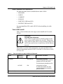
What precautionary messages mean
The types of precautionary messages used in Northern Telecom (Nortel)
documents include attention boxes and danger, warning, and caution
messages.
An attention box identifies information that is necessary for the proper
performance of a procedure or task or the correct interpretation of information
or data. Danger, warning, and caution messages indicate possible risks.
Examples of the precautionary messages follow.
ATTENTION Information needed to perform a task
ATTENTION
If the unused DS-3 ports are not deprovisioned before a DS-1/VT Mapper
is installed, the DS-1 traffic will not be carried through the DS-1/VT
Mapper, even though the DS-1/VT Mapper is properly provisioned.
CAUTION
Possibility of service interruption or degradation
CAUTION
Possible loss of service
Before continuing, confirm that you are removing the card
from the inactive unit of the peripheral module. Subscriber
service will be lost if you remove a card from the active unit.
DMS-100 Family EIU User Guide TELECOM12
xviii
CAUTION
Possibility of equipment damage
CAUTION
Damage to the backplane connector pins
Align the card before seating it, to avoid bending the
backplane connector pins. Use light thumb pressure to align
the card with the connectors. Next, use the levers on the card
to seat the card into the connectors
CAUTION
Possibility of static electricity damage
CAUTION
Static electricity damage
Wear a static discharge wrist strap connected to the wriststrap grounding point of a frame supervisory panel (FSP) or
a modular supervisory panel (MSP). This precaution protects
the cards against damage caused by static electricity.
DANGER
Possibility of personal injury
DANGER
Risk of personal injury
Handle the card by the edges only. Do not touch the
components on the card. These components reach very high
temperatures, and can burn causing personal injury.
DANGER
Possibility of electrocution
DANGER
Risk of electrocution
Do not open the front panel of the inverter unless fuses F1,
F2, and F3 have been removed. The inverter contains high
voltage lines. Until the fuses are removed, the high voltage
lines are active, and you risk being electrocuted.
How commands, parameters, and responses are represented
Commands, parameters, and responses in this document conform to the
following conventions.
Input prompt (>)
An input prompt (>) indicates that the information that follows is a command:
>BSY
297-8991-910 Standard 03.01 August 1999
xix
Commands and fixed parameters
Commands and fixed parameters that are entered at a MAP terminal are shown
in uppercase letters:
>BSY
CTRL
ctrl_no
Variables
Variables are shown in lowercase letters:
>BSY
CTRL
ctrl_no
The letters or numbers that the variable represents must be entered. Each
variable is explained in a list that follows the command string.
Responses
Responses correspond to the MAP display and are shown in a different
typeface:
FP 3 Busy CTRL 0: Command request has been submitted.
FP 3 Busy CTRL 0: Command passed.
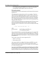
The following excerpt from a procedure shows the command syntax used in
this document:
Step
Action
1
Start the FTP tool by typing
>ftp nnn.nnn.nnn.nnn
and pressing the Enter key.
where
nnn
is the portion of the IP address that identifies the node
Example:
>ftp 47.187.112.215
Example of a MAP response:
Allocated a Session ID Successfully 220 bcaryfc6 FTP
server
(Version $Revision: 1.21 $ $Date: 88/12/21 10:19:25 $) r
DMS-100 Family EIU User Guide TELECOM12
xx
297-8991-910 Standard 03.01 August 1999
21
Chapter 1: Introduction to the EIU
This chapter describes the Ethernet interface unit (EIU).
CAUTION
Possible loss of network security
Using the EIU and a telnet or file transfer protocol (FTP)
session to establish a maintenance and administration
position (MAP) session can introduce a security risk to both
the DMS node and its subtending network.
When establishing and operating a MAP session in this way,
there is limited security for clear text (user identification and
passwords) and for Internet Protocol (IP) addresses for
screening. This limited security makes an open local area
network (LAN) vulnerable to entry by unauthorized persons.
Nortel recommends that the operating company, as a
minimal precaution, integrate intermediate security servers
with encryption to avoid unauthorized access to the switch.
For alternative approaches, contact your Nortel
representative to discuss state-of-the-art secure OA&M data
communications equipment products.
By using the EIU, telnet, and FTP software, the operating
company assumes any and all risks associated with the
implementation and use of this hardware and software.
Topics in the chapter include the following:
•
overview of the EIU
•
system architecture
•
hardware description
•
limitations and restrictions
•
feature packaging
DMS-100 Family EIU User Guide TELECOM12
22 Chapter 1: Introduction to the EIU
•
EIU provisioning requirements
•
billing
•
service orders
•
user interface characteristics
•
logs, alarms, and operational measurements (OM)
Overview of the EIU
The EIU is an application-specific unit (ASU) that supports Ethernet
connectivity on the DMS-100 switch. You can configure the EIU as either an
IP router or an OSI router. The EIU also supports host services.
The EIU is intended primarily as a high-speed interface that provides
connectivity in a co-located environment such as that in a Central Office.
However, if the EIU is deployed in a LAN extending beyond the co-located
environment, you should observe the limitations and network security notes in
the caution above.
The following list summarizes the router and host services that use dedicated
EIUs. For general information on ASUs, refer to “Appendix G: ASU
background information”.
Note: The following applications may not be available in all product lines
or markets. For more information, consult with the specific Product Line
Manager or contact Nortel Networks.
•
Automated directory assistance service (ADAS). ADAS provides
assistance to an operator by automatically prompting subscribers for
directory assistance information. ADAS uses the EIU to support
messaging between an ADAS OA&M position and the DMS-100 switch.
•
Billing server. Billing server allows the DMS-100 switch to forward
billing and OM information from a DMS file processor (FP) to an external
operating company billing processor. The OM data is sent to the
downstream processor through a different EIU. The system throttles the
billing server traffic at 36 kbyte/sec. Note that this application is only
supported on DMS-250 or combinations with DMS-250 and GSM product
lines.
•
Automatic file transfer (AFT). The AFT application lets the operating
company use TCP/IP to transport billing and operational measurement
(OM) data from the DMS-250 IOC (input/output controller) disks to the
downstream processor over an Ethernet LAN. One EIU can support both
billing and OMs. For this application, the recommended number of EIUs
is two: one EIU is dedicated to billing data and the other is to OMs.
AFT is also referred to as Madley AFT. Limited availability.
297-8991-910 Standard 03.01 August 1999
Chapter 1: Introduction to the EIU 23
•
Cellular digital packet data (CDPD). The CDPD service transports
datagrams between the mobile and private/public data networks.
•
Programmable service node (PSN). PSN is a flexible platform that lets
operating companies rapidly deploy advanced services into their network.
Deployment is achieved through a service control unit (SCU). The SCU is
an external computing platform that controls the call processing on the
switch using a high-speed data link.
•
Remote management system (RMS). RMS provides telnet and file
transfer protocol (FTP) functionality to the DMS-250 switch. Telnet is a
protocol for remote terminal access.
•
Intelligent Call Manager (ICM). ICM provides the protocol support for
Computer Telephony Integration applications (for example, Symposium
Call Center Server, SSCS) in accessing the DMS via TCP/IP protocols.
System architecture
The data communications environment supports data links that are not tied to
the call processing network functions of the switch. These links do not use the
DMS network or line access capabilities. This characteristic is important when
supporting OAM links. These links must become functional in the early stages
of switch initialization and remain functional through all but catastrophic
failures, including call processing failures.
The EIU is a gateway between the DMS-bus and an Ethernet that supports user
data links. The EIU is a concentration point between remote peripherals
(workstations, terminals, and routers) and the DMS-bus. The remote
peripherals are not terminated on the EIU, but on concentrators. These remote
peripherals allow the network engineers to connect alternate link levels and
asynchronous terminal equipment (MAP terminals, printers, and so on) to the
system. The Ethernet also provides a link between the DMS-100 switch and
the workstations used for processing.
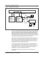
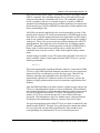
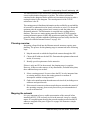
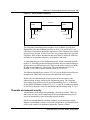
Figure 1 shows an overview of the architecture of the enhanced SuperNode
system.
DMS-100 Family EIU User Guide TELECOM12
24 Chapter 1: Introduction to the EIU
Figure 1
Overall architecture of enhanced SuperNode system
SLM
9-track tape
DMS-core
Network
IOC
DMS-bus
SOS
SOS
UNIX
SOS
FP
(flexible
file system)
AP
(provisionable
computing)
AP
(provisionable
computing)
EIU
Ethernet
Communications server
(flexible data
communications interface)
Workstation
X.25
DMS-bus interface and expansion
Two methods are used to interface processing engines to the DMS-bus. Direct
links between the processors and the DMS-bus is the primary method for
establishing this connection. A secondary method involves the LPP, which is
used to fan out the message switch (MS). By having two methods, the DMS100 switch has the flexibility for provisioning software functions to processors
based on price, performance, and packaging criteria.
The LPP extends the MS fanout within a single cabinet. This fanout is
accomplished by using a second-level MS pair to provide switching, and by
extending the messaging capability through an extended messaging bus. These
297-8991-910 Standard 03.01 August 1999
Chapter 1: Introduction to the EIU 25
second-level message switches are referred to as local message switches
(LMS).
The frame transport bus (F-bus) is a 32-Mbit/s messaging bus that resembles
the MS in its protocol. The use of a narrower data path allows access to two
buses through a single backplane. This feature lets a single processor card
connect to both planes of the LMS and to survive faults on one plane. Links
interconnecting planes of the LMSs are provided to allow transparent message
rerouting in the case of single faults.
Note: Because the interconnecting F-bus is a wire bus, it is limited to a
single cabinet.
Inter-message switch links required with LPP
Inter-message switch links (IML) between the MS planes are also required to
improve robustness. For example, two peripherals (such as an applications
processor and an EIU) can lose communication with each other if they
message through different planes of the MS. In this scenario, assume that one
peripheral is messaging through plane 0 only because of a failure. If the second
peripheral loses its link to plane 0, the two peripherals cannot communicate
even though they can communicate to the DMS-core for maintenance
purposes.
For this reason, there is a pair of IMLs in integrated service node (ISN)
switches. These IMLs are DS512 links that operate at 1024 Kbit/s. Other
improvements to the MS hardware are also required to conform with the ISN
maintenance strategies.
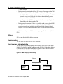
Data communications interface architecture
The overall architecture of the data communications subsystem is based
partially on the premise that the processing and the access method for these
entities must be separate.
For this reason, application processors (AP) have the intelligence to drive the
link protocols. This arrangement allows freedom to change access methods
and allows flexibility in satisfying the processing requirements for each
protocol. The emphasis is on providing locally attached, nonswitched
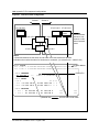
connections primarily for OAM interfaces. An example of the overall data
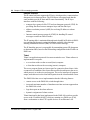
flow for the data communications environment is shown in figure 2.
DMS-100 Family EIU User Guide TELECOM12
26 Chapter 1: Introduction to the EIU
Figure 2
Ethernet interface data flow
DMS-bus
Messaging path
User AP
(protocol
processing, for
example, terminal drivers)
Data
communications
processor
(transport
interface)
Ethernet
LAN
Workstations
Communications
server
Terminals
Data
links
Given the cost of the SuperNode cabinet infrastructure, providing the standard
hard connection interfaces in this mechanical environment is not possible. For
this reason, interfaces are placed outside the boundaries of these cabinets.
Engineering approaches to LANs also address a similar problem. In LANs, it
is not economic to provide all types of data interfaces at each node on the LAN.
The communications server provides a range of communications services to all
users on the LAN and may be located anywhere on the LAN.
Another major functional requirement that the EIU satisfies is providing
connectivity to commercially available workstations for value-added services.
This requirement is provided through a standard interconnect media. The
majority of these workstations support an Ethernet interface for local area
networking. The EIU also supports this protocol.
The EIU supports packet communication into a LAN. The standards for its
physical implementation are defined in IEEE 802.3. The EIU supports a
10 Mbit/s base band bus type of LAN for broadcast. The LAN uses a carrier
sense multiple access with collision detection (CSMA/CD) method for
arbitrating access to the communications channel.
Lastly, the EIU also provides a protocol gateway into the DMS-100
environment.
297-8991-910 Standard 03.01 August 1999
Chapter 1: Introduction to the EIU 27
The Ethernet interface takes advantage of commercially supported peripherals
and functions. These interface devices are selected and qualified for
applications in the DMS-100 switch, with particular attention to hardware
compliance, maintainability, and the protocol set provided. The following
devices are commercially available:
•
LAN repeaters to locally extend the range of the LAN
•
LAN gateways to extend the range of the LAN to a metropolitan-area
network (MAN) or a wide-area network (WAN)
•
asynchronous terminals and printers through communications servers at up
to 19.2 Kbit/s
•
synchronous data links through communications servers at up to 56 Kbit/s
•
IBM mainframe access through channel interconnect units
•
workstations (for example, Sun, HP, IBM), Macintoshs, and PCs
•
servers
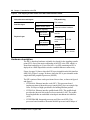
The EIU is a simplex engine. A simplex engine is sufficient for the EIU
because the facilities that are connected through the EIU are not critical to the
operation of the switch (that is, for call processing). Sets of EIUs may be used
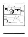
with one or more EIUs available as a warm standby spare. The mapping of the
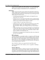
EIU architecture to the OSI reference model is shown in figure 3 on page 28.
For more information on EIU sparing, refer to “EIU sparing and redundancy”
on page 41.
DMS-100 Family EIU User Guide TELECOM12
28 Chapter 1: Introduction to the EIU
Figure 3
EIU mapping to lower levels of the OSI communications model
OSI reference model layers
EIU partitioning
Logical link control
EIU software
Data link Layer
Media access control
Ethernet interface hardware
Physical signaling
Attachment
unit interface
Physical Layer
Attachment
unit interface
AUI PB
15-conductor
connectorized
cable
Media access unit
External
equipment
Transmission medium
RG-58 coaxial
cable
UTP PB
4-wire twisted
pair, LAN hub
Hardware description
The EIU is based on hardware originally developed for the signaling transfer
point (STP). One of the main components of the STP is the LPP, which is a
frame that can hold up to 36 two-slot ASUs. An LPP containing an EIU is
deployed in a DMS SuperNode switch to establish Ethernet connectivity.
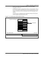
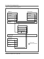
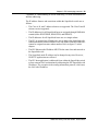
Figure 4 on page 29 shows where the EIU is provisionable on the link interface
shelf (LIS). Figure 5 on page 30 shows where the EIU is provisionable on the
single-shelf link peripheral processor (SSLPP).
The EIU consists of three cards provisioned in two slots, as shown in figure 4
and figure 5:
•
NT9X84AA, Ethernet interface card (EIC). This processor board
implements most of the media access control (MAC) layer on a single chip.
It has 384 kbyte of high-speed buffer for holding Ethernet packets.
•
NT9X85AA, Ethernet interface paddle board (EIP). This paddle board
provides the physical link to the local area network (LAN). The paddle
board implements an unshielded twisted-pair attachment unit interface
(AUI).
•
NTEX22BA/BB, Integrated processor and F-bus card (IPF). This
processor board contains a Motorola M68020 processor and 8 Mbyte of
297-8991-910 Standard 03.01 August 1999
Chapter 1: Introduction to the EIU 29
RAM. The NTEX22CA provides 32 Mbyte of RAM and higher
throughput performance.
NTEX22 also contains a peripheral bus (P-bus) to F-bus interface. The Pbus to F-bus interface connects the processor bus with the frame bus, which
in turn is connected to the local message switch (LMS) through the rate
adaptor.
The IPF card is a common processor card used by almost all ASUs and
runs the Support Operating System (SOS).
Figure 4
Link interface shelf, with 2-slot EIU locations
Top view of LIS shelf
2-slot ASU
Rear paddle boards
NT9X85
Ethernet AUI PB
2-slot EIU
Front cards
NT9X84 Ethernet interface card
NTEX22
Integrated processor and F-bus card
DMS-100 Family EIU User Guide TELECOM12
30 Chapter 1: Introduction to the EIU
Figure 5
SSLPP, with 2-slot EIU locations
Top view of SSLPP shelf
2-slot ASU
Rear paddle boards
NT9X85
Front cards
Ethernet AUI PB
NT9X84
2-slot EIU
NTEX22
Ethernet interface card
Integrated processor and F-bus card
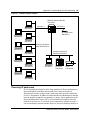
Figure 6 shows the placement of an LPP provisioned with an EIU on a DMS
SuperNode switch.
Figure 6
DMS SuperNode switch LPP with an EIU
F-bus 0
MS 0
DS30 links
EIU
LMS
plane 0
EIU
MS 1
Ethernet
LMS
plane1
EIU
F-bus 1
Figure 7 shows EIU links to the MS on the fiberized link interface shelf (FLIS).
297-8991-910 Standard 03.01 August 1999
Chapter 1: Introduction to the EIU 31
Figure 7
DMS SuperNode FLIS with an EIU
F-bus 0
MS 0
DS512 links
EIU
Bus
plane 0
EIU
MS 1
Ethernet
Bus
plane1
EIU
F-bus 1
Ethernet interface card (NT9X84)
The EIC is based on commercial Ethernet interface chips. It supports one
Ethernet communications link and processes all of the level 1 and part of the
level 2 protocols for the Ethernet in hardware.
The card consists of a common message buffer that is accessed by both the
processor and the Ethernet interface chip. On the Ethernet side, an independent
controller uses memory-based data structures to locate and transmit and
receive data from the links. The controller chip is an Advanced Micro Devices
AM7990 LANCE device (a LAN controller for Ethernet) with support devices.
The buffer memory is organized as 192 kilowords x 16 bits (384 kbyte) with
parity, and is directly accessible by the processor. Both byte and word access
is supported. The processor and the Ethernet control chip contend for access to
this memory. The architecture of the memory controller ensures that sufficient
memory access bandwidth is allocated to the Ethernet controller, so that
underrun or overrun conditions do not occur during transmission or reception
of a message.
Figure 8 illustrates the memory and buffer architecture.
DMS-100 Family EIU User Guide TELECOM12
32 Chapter 1: Introduction to the EIU
Figure 8
Ethernet interface architecture
P-bus
LPP
NTEX22
CPU/IPF
Ethernet
Ethernet
memory
controller
Multiport
buffer memory
Ethernet
controller
MAU
Ethernet
coaxial cable
Ethernet physical interfaces
The physical interface to the Ethernet system is defined by the paddle board
located behind the EIC. The interfaces available are described in the following
sections.
Attachment unit interface—NT9X85AA
This card is a 15-pin D-type connector that provides the interface between the
Ethernet controller and the media access unit (MAU). This is the most generic
interface and supported as an industry standard (IEEE 802.3 10Base5
implementation).
Note: This interface is compatible with all implementations of Ethernet
through external equipment.
The MAU is different depending on the implementation of the LAN.
For a 10Base5 coax LAN, the MAU has coaxial connections on either side
using field installed N-type connectors. The AUI connection is on an adjacent
side. The coax cable is about 0.5 in. in diameter and has a bending radius of
0.5 m and the minimum amount of cable between transceivers is 2.5 m. These
physical restrictions must be taken into account when installing the MAU.
MAUs have a range of 500 m per bus segment which may be bridged together
to form a LAN that is a maximum of 2500 m long. The disadvantages of this
implementation are installation and difficulty of maintenance.
297-8991-910 Standard 03.01 August 1999
Chapter 1: Introduction to the EIU 33
For a 10BaseT twisted-pair LAN, the AUI connection is usually on one side
with an RJ-11 telephone jack on the other. Typically, standard office four-wire
circuits are used to connect the MAU to the hub. The hub is an electronic
replacement for the multiple access properties of the coaxial cable. It generates
the broadcast function for each message received. It is usually an AC-powered
unit mounted in a 19-in rack. The hub has either RJ-11 telephone jacks or a
specialized interconnect through a punch-block distribution system.
Typical unshielded twisted-pair (UTP) systems offer a LAN radius of 100 m,
allow cascading of hubs, and may allow the use of other types of interconnect
(fiber or standard coax) to increase the radius. The star configuration, in
combination with the centralized electronic implementation of the LAN
function, allows fault location and isolation capabilities that are more in line
with standard DMS-100 maintenance practices.
Unshielded twisted-pair (NT9X85BA)
This interface contains a UTP MAU and hub integrated onto the paddle board.
The card provides a 4-wire twisted-pair connection externally. Up to four
external LAN devices can be connected to the hub. This development provides
a cost reduction over an OEM 10BaseT LAN configuration and puts
maintenance of the hub more in line with standard DMS-100 maintenance
practices.
Grounding requirements
Isolated system ground (ISG) is not mandatory. The EIU will operate properly
in both ISG and non-ISG environments. This section provides information on
grounding for equipment and facilities associated with the EIU.
ISG issues are most prevalent in the area of Ethernet peripherals. Because
these devices are AC powered, they may violate the ISG requirements. Devices
can be powered from a protected AC source to isolate the frame and logic
grounds and to provide continued service in the event of a commercial AC
power failure.
In addition, the implementation of the AUI is not compliant with the IEEE
802.3 specification. In particular, the shield of the AUI cable is not connected
to logic ground. Instead, the cable is connected to frame ground to satisfy the
ISG requirement. The Ethernet interface is further transformer-isolated in the
transceiver (the MAU) and the shield ground is capacitively coupled to the case
of the unit.
Capabilities, limitations, and restrictions
This section describes the known limitations and restrictions for the EIU.
The operating company can install the EIU only on SuperNode shelves,
including the LPP (but not the 24-slot LPP), FLIS, and SuperNode SE link
DMS-100 Family EIU User Guide TELECOM12
34 Chapter 1: Introduction to the EIU
interface shelf (SNSE LIS). Nortel has tested the EIU for installation,
operation, administration, and maintenance on each of these platforms.
EIU hardware capabilities and limitations
The following points describe EIU-specific limitations:
•
An Ethernet message is 1518 bytes long, including 128 transmit and 128
receive buffers.
•
The EIP (NT9X85AA) implements the unshielded twisted-pair AUI
interface, which provides the physical link to the LAN. The EIC
(NT9X84AA) implements most of the MAC layer.
•
Only the 2-card EIU, based on the IPF (NTEX22BA/BB), is supported.
•
The 4-Mbyte EIU (NTEX22AA) is not supported.
•
The 8-Mbyte EIU, based on the IPF NTEX22BB, is now standard. All
customer sites must upgrade.
•
The EIU and the TCP/IP protocols are suitable for connecting low- to
medium-speed peripherals, such as terminal servers and workstations, to
the SuperNode switch.
The EIU acts as an IP router for IP capable nodes such as the DMS-core,
file processors (FP) and application processors (AP). The EIU can perform
this function subject to the limitations identified in this document. The
TCP/IP protocols allow interworking with a very large number of third
party vendor’s equipment.
•
The EIU, unlike equipment from many other major manufacturers, can
withstand a broadcast storm1 or a babbling node. This capability is
possible because of the overload control feature. This capability follows
the standard DMS-100 maintenance philosophy, which states that a node
must be maintainable even under overload conditions.
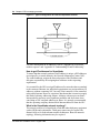
In a lab environment, it has been demonstrated that a moderately heavily
loaded LAN with broadcast messages caused workstations and a router to
lock up, while the EIU remained functional. The workstations were
overloaded to the point that all activity within the operating system
stopped:
— the on-screen clock stopped ticking
— the cursor did not respond to mouse movements
— keystrokes were ignored
— outgoing LAN activity stopped
1. A broadcast message is issued from a single node and is received and processed by all nodes
on the network. A broadcast storm occurs when a faulty node broadcasts a message to all other
nodes for which it expects a reply. For each reply, the node may in turn issue another broadcast
message causing the number of messages to multiply rapidly until the network is congested.
297-8991-910 Standard 03.01 August 1999
Chapter 1: Introduction to the EIU 35
— programs were not aware that a period of time had elapsed
— The router stopped routing packets.
The EIU remained fully functional throughout the broadcast storm test.
Although traffic from the EIU stopped, this stoppage was due to all other
components on the LAN being nonfunctional and there was nothing left for
the EIU to communicate with. The test demonstrated that maintenance
personnel could remote login to the EIU, start a CI process, look at some
OMs, and remote logout. The EIU could also successfully complete an inservice test and could be manual busied, then returned to service after
successfully completing the out-of-service test.
•
IP throttling was introduced to address customer concerns on co-residency
of EIUs with other ASUs in an LPP frame. The IP throttling feature
provides partial protection for the DS30 links at the expense of EIU
throughput. Similarly, throttling has been implemented for EIUs on FLIS
and SNSE LIS to protect the links between the MS and EIU from
overloading.
When deployed, fiber SR128 links through the MS will provide enhanced
capacity to alleviate link capacity overload.
•
The SNSE LIS and LPP have been product integrity tested with up to eight
EIUs. Capacity engineering rules restrict the number of EIUs supported
per platform to less than eight. Refer to Provisioning Rules for LPP, SSLPP,
and SNSE LIS, System Engineering Bulletin SEB 92-02-001.
•
The DMS-100 switch supports a maximum of eight EIUs per switch. Each
of the eight EIUs can be configured on a separate LAN. However, EIUs
configured on the same LAN can provide simple load balancing of IP
traffic between EIUs, and tolerance to failure of a single EIU. For more
information on redundancy and sparing, refer to “EIU sparing and
redundancy” on page 41.
•
The EIU can screen IP packets whereby only IP packets from a specified
list of source IP address are accepted into the SuperNode switch and others
rejected. This list of IP addresses is bound in by and is the responsibility of
user applications (for example, EXNDINV).
•
OSI and TCP/IP protocols cannot co-exist on the EIU.
•
Theoretically, the EIU is capable of routing approximately 350 kbyte/s
with 1536 kbyte packets at the IP level. That measurement equals about 2.5
Mbit/s. This performance measurement is the rate at which the EIU routes
to the F-bus. However, throttling values limit throughput. Refer to
Provisioning Rules for LPP, SSLPP, and SNSE LIS, System Engineering
Bulletin SEB 92-02-001.
DMS-100 Family EIU User Guide TELECOM12
36 Chapter 1: Introduction to the EIU
System-wide limitations
The EIU is collocated in an LPP shelf with other ASUs such as the link
interface unit (LIU7) and frame relay interface unit (FRIU). The exact
configuration of ASU-type units depends on the applications. The LPP is
connected to the DMS-bus through eight DS30 links in a load-sharing
arrangement.
Each DS30 has a transfer capacity of approximately 256 Kbyte/s. A single EIU
can route long messages (1518 bytes) from the LAN to the DMS-bus at a rate
that can overload the DS30 and cause the link to fail (SysB state). This link
failure causes traffic to switch to an alternate DS30 link. If the system
maintains the level of traffic that caused the initial failure, each DS30 link
topples one by one until the LPP is isolated from the DMS-bus. Further, as
each DS30 link overloads, all pending messages on that link are lost, including
SS7 messages.
Note: When deployed, fiber SR128 links through the MS will provide
enhanced capacity to alleviate link capacity overload.
The IP throttling feature throttles IP messages to and from the EIU to provide
a measure of protection against DS30 link overload. Application groups can
engineer throttling to permit them to override the defaults. Complete
protection is still not guaranteed due to other message sources, such as SIPC,
MTS, logs, and OMs. Further, multiple EIUs on the same LPP can still
simultaneously send a large message on the same link which, when combined
with other messages in the LMS RX FIFO queue, can still cause an overload.
IP throttling has also been implemented to protect the links between the MS
and EIUs that are on FLIS or SNSE LIS.
A problem common to all ASU types is that the F-bus receive buffers can be
overloaded. If this happens too many times within a certain time interval, the
rate adaptor detects the error and fails the link. Engineering rules are required
to ensure any ASU type is not overloaded. Refer to Provisioning Rules for LPP,
SSLPP, and SNSE LIS, System Engineering Bulletin SEB 92-02-001.
Limitations associated with maintenance
The operating company can datafill a maximum of eight EIUs in the LIUINV
table. That is, the maximum number of EIUs on a switch is eight. As a further
limitation, each LPP can have a maximum of four EIUs. The FLIS can have up
to eight EIUs.
These limitations are not only a datafill issue. Other factors must be studied
before these values can be increased, such as traffic load through an LPP or
FLIS, EMI emissions, and routing issues. Currently, with 8 EIUs and 28 LIU7s
in a 36 processor LPP configuration, the emissions are just within allowable
limits.
297-8991-910 Standard 03.01 August 1999
Chapter 1: Introduction to the EIU 37
The Ethernet address in the LIUINV table has the format of the Nortel
SuperNode family range of addresses: X000075Fxxxxx, where X is
hexadecimal notation and x is a variable. For more information on MAC
addresses, refer to “Appendix I: Obtaining a MAC address”.
Diagnostics for the EIU test only the Ethernet interface card (EIC) and the
Ethernet interface paddle board (EIP). These diagnostics do not test the AUI
cable. The AUI cable attaches to the paddle board and to a connector in the
bulkhead. An extension of the AUI then runs from the bulkhead to the MAU.
Diagnostics also test the MAU. EIU diagnostics test the EIU’s connectivity to
the AUI and the MAU up to the HUB.
Lastly, the record start command cannot be initiated during a telnet session on
the connected device.
Limitations associated with protocols
Trailers are not supported. Trailers are the field on the data packet in which the
system places the “headers”, which normally precede the data, after the data.
Trailers can be negotiated between cooperating systems in an attempt to
improve efficiency.
In the DMS-core, the protocol stack runs in the SuperNode IP (SNIP)
scheduler class. This includes the IP receive processes and timer functions for
TCP. In all other nodes, the protocol stack runs in CP class. The initial
allocation for SNIP class is 3 percent and an interface is provided that allows
an application to modify this value.
The following sections describe specific limitations associated with protocols.
Routing information protocol
The size of the dynamic routing table is limited to 436 entries. This limitation
is imposed by the current implementation of and the current number of buffer
management system (BMS) buffers reserved for routing information protocol
(RIP) broadcasts. If the routing table overflows the routes at the end of the RIP,
the system ignores the messages. This situation can lead to unpredictable
routing behavior, such that routes may appear and disappear every 30 s. There
is no warning log to notify the operating company that this errant behavior is
occurring.
RIP Version 1.0 does not support variable-length subnetting. This limitation
means that all subnets that use RIP to exchange routing information must use
the same number of bits in their IP address to identify their subnet. If a subnet
does not adhere to this rule, unpredictable and intermittent loss-ofconnectivity behavior may be experienced on the EIU. RIP-II, which supports
variable-length subnetting, is not implemented on the EIU.
DMS-100 Family EIU User Guide TELECOM12
38 Chapter 1: Introduction to the EIU
TCP
Each TCP connection has its own state machine. For the number of allowed
connections, refer to Table 5, TCP connection limits by Supernode subsystem
in this document. There are also SOS limitations in that applications that
require hundreds or thousands of connections are not supported.
Internet Protocol and Internet Control Message Protocol
When an EIU goes ManB or SysB, any qualifying EIU that is available takes
over. The first EIU that failed broadcasts reverse-RIP messages advertising its
loss-of-connectivity to the network. In this way, the routers on the LAN that
are immediately notified of the second EIU takeover.
However, there is a worse case scenario in which the reverse-RIP messages are
lost on the LAN. As a result, the entry for the first EIU must time-out in the
routing table in each router before these routers start sending datagrams to the
second EIU. This time-out can take up to 3 min. This limitation is imposed by
the RIP implementation on the EIU. A possible option is to configure the
routers on the LAN to use only address resolution protocol (ARP) and not RIP
to communicate with the DMS-100 switch. However, the ARP-cache time-out
on the router must be set to a low value (1 min is the recommended time).
All subnet size combinations are permitted in table IPNETWRK. However, the
subnet size in the DMS-100 switch must be the same as the subnet size of the
LAN to which the DMS-100 switch is connected. This requirement is a result
of the limitation of the RIP version 1.0 implementation in the EIU. The IP
subnet must be allocated for each DMS-100 switch. Refer to “Addressing” on
page 50.
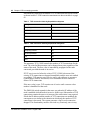
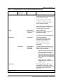
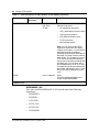
Feature packaging
Feature packaging applies to software loaded on the DMS-core. In general,
these packages provide the central maintenance functionality for the new
remote processors and the protocol software.
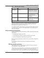
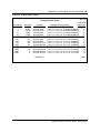
Prior to CSP02, the feature packages for the software resident in the DMS-core
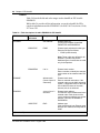
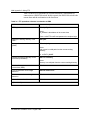
are summarized in table 1.
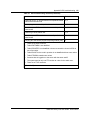
Table 1
DMS-Core feature packages
Package
Title
Description
NTXF05AA
Ethernet interface unit
The is the basic package
needed to datafill and
maintain the EIU. No protocol
software is included in this
package.
(Sheet 1 of 2)
297-8991-910 Standard 03.01 August 1999
Chapter 1: Introduction to the EIU 39
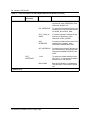
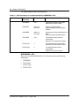
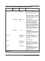
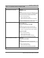
Table 1
DMS-Core feature packages
Package
Title
Description
NTXF19AA
TCP/IP
This package is the protocol
software from the transport
layer down to the link layer.
NTXF19AA uses NTXF05AA.
NTXS11AA
FTP
This package is the standard
FTP client and server
software. NTXS11AA uses
NTXF19AA.
NTX70AA
Telnet/RMAP
This package is the standard
telnet server for remote MAP
(RMAP) access.
(Sheet 2 of 2)
Software for peripheral processors is controlled through package lists that
define the entities for a specific load. The EIU may have several loads
depending upon the applications resident on it.
As of CSP02, the EIU-related software is packaged in LANCOMM. Software
is available with TL_ALL LCF. EIU-related software is provided as part of
order code TEL00001.
EIU provisioning requirements
The provisioning rules for the total numbers of EIUs depend on the following
requirements:
•
the applications running on the EIUs
•
the total application capacity required for all EIUs on the switch
•
the level of redundancy required by these applications
The provisioning requirements are subject to the maximum limit of eight EIUs
per switch.
The following sections describe the provisioning limits for the new
components.
DMS-bus inter-MS provisioning
Each message switch in an IML requires an NT9X17DA port card and an
NT9X20BB DS512 fiber paddle board.
Card position is not restricted. However, the cards associated with a link must
use the same slots in each MS. For example, if the cards in one MS are
provisioned in slot 21 (that is, the NT9X17DA is in 21F and the NT9X20BB
DMS-100 Family EIU User Guide TELECOM12
40 Chapter 1: Introduction to the EIU
is in 21R), the cards in the MS at the other end of the link must also be
provisioned in slot 21. This example is shown in figure 9.
Figure 9
Example of DMS-bus intermessage switch configuration
NT9X20BB DS512
fiber paddle board
Intermessage switch link
NT9X20BB DS512
fiber paddle board
MS
MS
Intermessage switch link
NT9X17DA port card
NT9X17DA port card
The following cards must also be provisioned on each switch:
•
a minimum of 16 Mbyte of memory using one of the following card
configurations:
— one NT9X13DB CPU card and one NT9X14DB memory card
— one NT9X13NA CPU card
•
one NT9X49CB MS tracer card
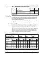
DMS-bus external MS provisioning
Just as the SuperNode core requires access to the DMS-bus, so do peripherals.
Therefore, DMS-bus port engineering is required.
297-8991-910 Standard 03.01 August 1999
Chapter 1: Introduction to the EIU 41
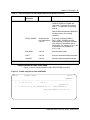
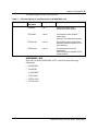
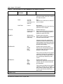
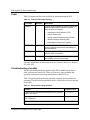
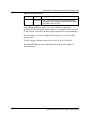
The information in table 2 defines the port requirements for EIU installation.
Table 2
DMS-bus port engineering requirements for peripherals
Peripheral
Message Switch
links per plane
LPP (DS-30)
4
Comments
Port Card
NT9X17AA
Paddle Board
NT9X23BA
1 LPP requires 1
MS port card
EIU provisioning
Provisioning of EIUs is application dependent. The number of EIUs required
and their configuration is determined by a combination of product and
software criteria. EIUs are not provisioned on a switch unless required by the
application.
Where possible, provision two or more EIUs connecting to a single LAN to
improve reliability. This redundancy may not be required if duplication is
provided at a higher system level (for example, duplicate LANs).
Observe the following provisioning rules:
•
although the maximum number of EIUs in a switch is limited to eight
(limitation imposed by software), the actual number that you can provision
per platform is determined by engineering rules (refer to Provisioning
Rules for LPP, SSLPP, and SNSE LIS, System Engineering Bulletin SEB
92-02-001
•
each EIU requires one LIU position (two slots) in a 36-position LPP
•
each EIU has a fixed memory capacity; the NTEX22BB contains 8 Mbyte
of RAM, and the NTEX22CA contains 32 Mbyte of RAM
For more information on datafill, refer to “Chapter 3: EIU datafill”. For more
information on maintenance impact on spares, refer to “EIU sparing
requirements” on page 101.
EIU sparing and redundancy
The DMS switch and the EIU support load balanced routing. Characteristics
related to provisioning and options are described in the following points:
•
In table IPNETWRK, one EIU is defined as the default for the CM.
•
In table IPROUTER, all EIUs are defined.
•
Maintenance software ensured that all EIUs are aware of the states of all
other EIUs. States are known for the following:
— links between the EIU and the LAN-side subnet
— links between the EIU and the SuperNode-side subnet
DMS-100 Family EIU User Guide TELECOM12
42 Chapter 1: Introduction to the EIU
— the EIU state
•
During normal operation, the default EIU routes all messages to the CM.
If there is a problem with the default EIU or its links, the following occurs:
— the default EIU advertises to the network that it is no longer available
(or in the event of a LAN-side link failure, the neighboring routers
cannot reach the default EIU)
— another provisioned EIU advertises that it is the router (net hop) to the
SuperNode-side subnet and the CM
•
During normal operations, if there is a problem with the non-default EIU
or its links, there is no impact on service unless the default EIU
experiences problems, in which case the SuperNode subnet is isolated
from the LAN-side subnet until one of more EIUs are brought back into
service.
Applications running on the EIUs must have sparing defined at the application
level.
Billing
EIUs do not directly affect billing functions.
Service orders
The EIU does not affect service order functions.
User interface characteristics
The EIU uses the existing peripheral user interface (UI) based on the DMS
MAPCI. The MAPCI includes additions to the PM level of the MAP display
to include the new hardware components. Figure 10 shows the hierarchical
relationship for the MAP levels used for the components.
Figure 10
MAP display level hierarchy
PM level
Existing
peripheral
modules
297-8991-910 Standard 03.01 August 1999
EIU level
EXND level
(LAN devices)
Chapter 1: Introduction to the EIU 43
Logs, alarms, and OMs
In general, the subsystems that generate logs, alarms, and OMs do not have
significant changes apart from the standard DMS-100 reporting sub-systems.
CAUTION
Possible loss of information
If a telnet session drops, logs and OMs may be lost.
Log reports
All logs from the EIU conform to the DMS OAM infrastructure. Log messages
are formatted in the DMS-core for display using the standard DMS log system.
Alarms
The EIU uses the DMS alarm system to report faults. Alarms are raised by
major maintenance state changes (usually brought on by hardware problems or
overload conditions). In addition, the MAP interface displays a composite
alarm banner across the top of the screen. This banner displays alarms with the
most urgent priority; as maintenance personnel clear the highest priority
alarms, next in priority display for each subsystem. In a healthy DMS-100
switch (that is, operations are normal), there are few alarms occurring.
Operational measurements
The EIU uses the DMS OM collection system to collect and distribute
operational measurements. The DMS OM subsystem also generates simple
reports. OMs can be transferred to “down-stream” processors for more
detailed analysis.
In general, operational measurements can be used to determine performance
and capacity in operational components. General types of operational
measurements gathered by the switch include the following:
•
error counts
•
I/O counts (operations completed)
•
CPU occupancy
DMS-100 Family EIU User Guide TELECOM12
44 Chapter 1: Introduction to the EIU
297-8991-910 Standard 03.01 August 1999
45
Chapter 2: EIU messaging protocols
This chapter describes the Ethernet interface unit (EIU) software architecture:
•
SuperNode software architecture
•
protocol engineering
•
Internet Protocol (IP) throttling
CAUTION
Possible loss of network security
Using the Ethernet interface unit (EIU) and a telnet or file
transfer protocol (FTP) session to establish a maintenance
and administration position (MAP) session can introduce a
security risk to both the DMS node and its subtending
network.
When establishing and operating a MAP session in this way,
there is limited security for clear text (user identification and
passwords) and for Internet Protocol (IP) addresses for
screening. This limited security makes an open local area
network (LAN) vulnerable to entry by unauthorized persons.
Nortel recommends that the operating company, as a
minimal precaution, integrate intermediate security servers
with encryption to avoid unauthorized access to the switch.
For alternative approaches, contact your Nortel
representative to discuss state-of-the-art secure OA&M data
communications equipment products.
By using the EIU, telnet, and FTP software, the operating
company assumes any and all risks associated with the
implementation and use of this hardware and software.
DMS-100 Family EIU User Guide TELECOM12
46 Chapter 2: EIU messaging protocols
Software architecture
The protocol stack supported on the DMS-core includes the following:
•
bootstrap protocol (BOOTP)
•
file transfer protocol (FTP)
•
IP
•
telnet
•
transmission control protocol (TCP)
•
user datagram protocol (UDP)
•
simple network management protocol (SNMP)
Software architecture also includes key protocols such as address resolution
protocol (ARP), Internet control message protocol (ICMP) and routing
information protocol (RIP)1.
Figure 11 shows the structure of the DMS-100 switch EIU protocol stack.
1. EIU only.
297-8991-910 Standard 03.01 August 1999
Chapter 2: EIU messaging protocols 47
Figure 11
SuperNode TCP/ IP protocol stack
Base_Tel-7
FTP
SNMP
TELNET
BOOTP
RIP
TLI (transport layer interface)
20, 21
161, 162
23
TCP
67, 68
520
UDP
ICMP
IP
ARP
GNI (generic subnet interface)
FTS
ETHERNET
The message flow between SuperNode nodes, and between SuperNode nodes
and external Ethernet LAN, is shown in figure 12 in this section.
DMS-100 Family EIU User Guide TELECOM12
48 Chapter 2: EIU messaging protocols
Figure 12
SuperNode TCP/IP message flow
DMS-core
File processor
Applications
Applications
TCP/UDP
TCP/UDP
IP
IP
FTS
FTS
DMS-bus
EIU
Applications
TCP/UDP
IP
FTS
Ethernet
Ethernet LAN
Workstation
Applications
TCP
IP
Ethernet
297-8991-910 Standard 03.01 August 1999
EIU as router
Inter-host connections
Chapter 2: EIU messaging protocols 49
Supported protocols
The EIU software is designed such that the EIU can be configured to run as
one of the following:
•
Internet host: EIU is involved only in supporting applications such as
Message Detail Recording for SS7 (MDR7)
•
Internet router: EIU is involved only in forwarding IP packets between
SuperNode and Ethernet LAN
•
Internet host and Internet router: EIU forwards IP packets between
SuperNode and Ethernet LAN, as well as supporting a local application
such as MDR7 on the EIU
•
Interface: EIU is similar to an internet router. The difference is that the
Supernode can be configured on an existing Ethernet subnet
Appendix F, “EIU supported configurations” in this document contains
diagrams of these configurations.
The following sections describe the protocols supported by the DMS-100
switch.
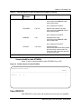
Boot protocol
Boot protocol (BOOTP) is a UDP/IP bootstrap protocol that allows a client
machine to discover its own IP address, the address of a server host, and the
name of a file to be loaded into memory and executed. A BOOTP server has
been implemented for the CM, a BOOTP relay agent for EIUs and a BOOTP
client for FPs (FEAT.AR1295).
BOOTP can be used to configure three types of IP hosts:
•
Nodes that reside on the DMS FPs. Once table IPNETWRK is datafilled,
each FP that does not already have an IP address sends a BOOTP request
to the CM. The latter allocates an address for the FP, adds a tuple in table
IPHOST with 20 TCP endpoints, 4 FTP client sessions, and 4 FTP server
sessions, and sends a BOOTP reply back to the FP. Refer to “TCP” on page
36.
•
Nodes that are part of the DMS product but not connected to the DMS-100
switch can be configured on an Ethernet LAN using EIUs. Such nodes
must be on the same subnet as the LAN side of the EIUs to be configured
through the BOOTP server on the CM, except if the maximum hops count
accepted by the relay agent and server is increased. The internal database
for BOOTP on the CM must be populated with information about such
nodes, for example by putting the required information in table
EXNDINV. The relay agents on EIUs forward relays requests and replies
between the clients on the LAN and the BOOTP server on the CM.
•
Nodes that are part of the DMS product, but that are connected to the DMS100 switch through an Ethernet LAN directly to the CM (that is, the CM
DMS-100 Family EIU User Guide TELECOM12
50 Chapter 2: EIU messaging protocols
has an Ethernet card). Such nodes have to be on the same subnet as the CM
to be configured through the BOOTP server on the CM, except if the
maximum hops count accepted by the server is increased.
File transfer protocol
File transfer protocol has been implemented on all the SuperNode-based nodes
including CM.
FTP implementation contains client as well as server software. The client
software lets the user application connect to a remote FTP server. The server
can be on any node within the SuperNode switch or a node external to the
SuperNode switch. The communication with the external node is through the
EIU. At least one EIU must be in-service in order to connect to an external
node. The SuperNode FTP server software listens to the incoming requests for
connection from a client FTP.
An FTP client has been implemented for launching manual FTP client sessions
from any SuperNode-based node to any node external or internal to the
SuperNode switch. The manual FTP can be invoked by issuing the following
command:
> ftp ‘<nnn.nnn.nnn.nnn>’ [x]
where
nnn.nnn.nnn.nnn
x
is the IP address of the FTP server
x is an optional port number
Observe that the IP address is enclosed within single quotes. For manual FTP,
a path name in lower case must be enclosed within single quotes. If the path
name is not enclosed within quotes and starts with a slash character(/), the path
name must be prefixed by a colon character (:). These restrictions are specific
to SuperNode CI.
There are three separate file systems supported by FTP:
•
SFDEV (on all nodes)
•
SLM volumes on CM
Also, access to the IOC is available. SLM volumes and SFDEV are recordoriented file systems, whereas FTFS volumes are byte-stream oriented.
Therefore, take extra care to identify the record lengths while transferring files
to a record-oriented file system.
For example, LOAD68K files require 256-byte fixed-length records. UnIPLed
images are stored as 512-byte fixed-length records. IPLed images need 1020byte fixed-length records. The record length can be set either automatically or
manually. If the file extension is in a prescribed form, the system automatically
297-8991-910 Standard 03.01 August 1999
Chapter 2: EIU messaging protocols 51
detects and sets the record length. To manually set the record length, use the
LRECL command. This command changes the record length locally at the
client site and sends the command to the server. The command is applied
locally, regardless of the server response (negative or positive). Both the
automatic record length detection process and the manual process require that
the file transfer type (ASCII or BINARY) be manually set to the required value
before transferring the file.
ASCII files can also be transferred to the record-oriented file systems. If the
transfer mode is binary, FTP switches automatically to FIXED length records.
If the file size of the file being transferred to the SuperNode switch in binary
mode is not a multiple of the current record length, the last record is padded
with spaces. This is a file system restriction and has nothing to do with FTP
implementation. This restriction can be eliminated by providing a separate
QUOTE command for FTP which toggles the record type (FIXED/VAR) in
binary mode. For files that do not meet the above criteria, the QUOTE
command can be issued to switch to VAR record length for binary transfer
mode.
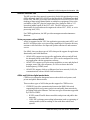
Volume listing is available via any FTP connection to the DMS-100 switch. To
list the available volumes when connected to the DMS FTP server, type the
following command:
ws>ls /
The system automatically capitalizes filenames when it is connected to a DMS
FTP server. The DMS SuperNode filename convention is to use an uppercase
format for all files even though it provides for lower case. Therefore, any
filenames included with commands sent to the DMS FTP server are
automatically capitalized. If a filename needs to be lowercase, enclose the
filename in single quotation marks to prevent automatic capitalization of the
filename.
Since the DMS SuperNode system does not have a global security concept, the
FTP server implementation contains a security mechanism. This mechanism
relies on the applications to inform about the potential userIDs and passwords
for valid FTP logins from remote FTP clients. The applications reserve a
number of FTP server sessions and provide a set of valid userIDs and
passwords. This information is kept as a database and is compared with the
userID-password combination whenever a remote client tries to login.
The activation and deactivation of the FTP layer on a node is controlled by the
datafill in table IPHOST. The tuple for a particular node contains the number
of server and client sessions allowed on that node. These numbers map
correspondingly into simultaneous FTP server and client processes.
DMS-100 Family EIU User Guide TELECOM12
52 Chapter 2: EIU messaging protocols
Internet Protocol
The IP control software supports the IP logic, which provides a connectionless
datagram service between hosts. The IP software is designed such that the
same modules provide IP host and IP router functionality. The IP layer
interfaces with the following:
•
transport layer protocols like TCP and user datagram protocol (UDP) for
providing data flow between transport layer and data link layer
•
address resolution protocol (ARP) for resolving IP address to subnet
address
•
Internet control message protocol (ICMP) for handling IP control
messages to and from other IP nodes
The IP routing table is maintained through static datafill in IP tables in DMScore and through dynamic routing information available either through
Routing Information Protocol (RIP) or ICMP redirect message.
The IP throttling process is responsible for transmitting queued IP datagrams
to destination nodes, based on the IP throttling configuration in the IP tables in
DMS-core.
Telnet
Telnet is an application protocol for remote terminal access. Telnet software is
implemented in two parts:
•
a server that resides on the accessed (host) computer
•
a client that resides on the accessing (remote) computer
The server program listens at a known port for connection from clients. After
a connection is established, the client redirects all keyboard input to the server,
which passes it on to the accessed program. The server intercepts all program
output, and redirects it to the client which prints it on the client machine screen.
The DMS-100 telnet server implementation has the following features:
•
remote access to the DMS-100 switch through telnet
•
increased maximum number of simultaneous telnet sessions supported on
the DMS-100 switch
•
logs that report on the telnet software
•
dynamic assignment of telnet sessions
Telnet functionality has been implemented in the DMS-100 switch to provide
access to the CI and the MAPCI, which are running on a DMS-core (CM),
from a workstation or other FTP-capable devices on an Ethernet LAN.
297-8991-910 Standard 03.01 August 1999
Chapter 2: EIU messaging protocols 53
The MAPCI supports asynchronous output to both the scroll area and a “full
screen” area. The input, however, is buffered in a line-by-line mode. This
combination of features requires that the telnet client perform echoing of input
characters.
The telnet server translates MAP display updates into VT100 character strings
and sends them to the telnet client at the remote end. Telnet clients must
directly connect to the CM using the CM address.
Transmission control protocol
TCP is a reliable transport layer protocol that provides communications
services to various applications like telnet, FTP, and so on. TCP can reside on
all the nodes capable of running Internet software. SuperNode TCP
implementation is able to interoperate with most of the industry-standard TCP
implementations.
User datagram protocol
UDP protocol provides connectionless transport protocol services unlike TCP,
which provides connection-oriented transport services. The original
SuperNode application for UDP is routing information protocol (RIP) on an
EIU. The IP route path display tool is also using UDP for intra-SuperNode
messaging between processes on different nodes. The UDP is designed such
that it can use IP fragmentation and reassembly functions to support UDP
datagram size of up to 4 kbyte.
Address resolution protocol
The address resolution protocol (ARP) protocol implements the address
resolution protocol, which provides dynamic binding between IP address and
a physical hardware address. ARP resolves IP address-to-Ethernet or MAC
address translation through ARP protocol running on an EIU. The IP address
to frame transport address (FTA) translation is done in ARP through simple
static table lookup.
Internet control message protocol
The ICMP software provides the IP status and error-reporting mechanism,
which is very closely coupled to IP. The ICMP messages handling in
SuperNode is limited to a few specific messages. The ICMP echo and response
messages are handled to provide ping capability. The ICMP redirect is handled
to provide routing table updates to SuperNode hosts from the dynamic routing
information on the EIU. TCP is notified of ICMP source quench messages.
Routing information protocol
The industry standard RIP is implemented for an EIU to enable it to participate
in the exchange of dynamic routing information with other IP routers on the
Ethernet LAN. The dynamic routing information is required on the SuperNode
to be able to route datagrams to hosts on distant LANs.
DMS-100 Family EIU User Guide TELECOM12
54 Chapter 2: EIU messaging protocols
Upon receiving RIP update from either another EIU or IP router on the LAN,
the RIP software updates internal IP routing table. According to RFC1058,
RIP response messages are transmitted every 30 s to Ethernet LAN.
Addressing
Within a single SuperNode switch, multiple hosts and multiple applications
within a single host may simultaneously request TCP/IP services. To provide
for application address uniqueness across the network, the following TCP/IP
address allocation scheme is used:
•
TCP/UDP provides individual PORT numbers to distinguish between
applications in the same host.
•
Each host processor in the Internet SuperNode switch is assigned a unique
IP address. This is a logical address, and when concatenated with TCP port
number, forms a unique network end-point or “socket”.
•
A unique IP address is required per hardware device.
•
Within the network, each node is physically identified by its own unique
physical hardware address. The logical IP address is translated to a
physical hardware address prior to datagram delivery to the destination
node.
•
Within a SuperNode switch, each node such as DMS-core, FP, and EIU has
a unique FTA, which is the physical hardware address on the SuperNode
subnet. The EIU also has a media access control (MAC) address, which
uniquely identifies it on the Ethernet LAN.
•
IP broadcast is not supported on the SuperNode subnet since the physical
layer does not support this.
MAC addresses
A unique media access control (MAC) address is assigned to each EIU through
table control datafill in table LIUINV. The norm within the industry is that the
MAC addresses are hard-coded in ROM. The EIU is different from industry
norm in this case. There is a flexibility of assigning the MAC address to the
EIU and at the same time the flexibility can result in problems if the addresses
are not assigned uniquely to the EIUs.
Only 48-bit MAC addresses are supported by the SuperNode switch.
For more information on MAC addresses, refer to “Appendix I: Obtaining a
MAC address”.
Internet addresses
The logical Internet address is analogous to physical or subnet addressing in
which each host is assigned unique integer address called the Internet address
or IP address. The Internet address integers are not assigned randomly, but are
assigned to nodes in such a way that Internet routing is more efficient. Refer to
297-8991-910 Standard 03.01 August 1999
Chapter 2: EIU messaging protocols 55
“Appendix E: Understanding IP and IP addressing” for more information on
Internet addressing.
The IP address features and restrictions within the SuperNode switch are as
follows:
•
The Class A, B, and C address schemes are supported. The Class D and E
schemes are not supported.
•
The IP addresses for all SuperNode hosts are assigned through DMS table
control (tables IPNETWRK, IPROUTER, and IPHOST).
•
The IP addresses for all SuperNode hosts are on a single subnet.
•
The EIU is assigned two IP addresses: one to address the SuperNode side
subnet and other to address Ethernet LAN side subnet. Both EIU addresses
cannot be assigned on same subnet number. Refer to figure 13 in this
chapter.
•
The EIU Ethernet side IP address MUST be the same class and network as
the SuperNode side.
•
The SuperNode node IP address can be changed at any time. However,
UDP/TCP applications are affected.
•
The EIU host application is addressed from within the SuperNode switch
or from external LAN workstations by addressing the EIU SuperNode side
IP address. The exception is the routing information protocol, which uses
the LAN side IP address.
DMS-100 Family EIU User Guide TELECOM12
56 Chapter 2: EIU messaging protocols
Figure 13
Typical configuration for LAN and SuperNode subnets
CM
SuperNode-side subnet
EIU
EIU
LAN-side subnet
For more information on IP addresses, refer to “Appendix H: IP network
number requests” and “Appendix E: Understanding IP and IP addressing”.
How to get IP addresses for SuperNode
To ensure that the network portion of an IP address is unique, all IP addresses
are assigned by a central authority, the Network Information Center (NIC).
The central authority assigns the network portion of the IP address and
delegates responsibility for assigning host addresses to the requesting
organization.
It is essential for the NIC to assign IP addresses for networks that are attached
to the connected Internet. An individual organization may assign arbitrary IP
addresses without contacting NIC, but only if their network is not connected
to the public Internet. However, experience has shown that it is unwise to apply
this kind of arbitrary addressing scheme. Arbitrary schemes prevent future
interoperability and may cause significant problems and down time when
converting to NIC-assigned addresses in future. It is strongly recommended
that the operating company obtain official Internet addresses from the NIC.
What is the SuperNode network topology?
The network consists of a SuperNode switch and other third-party equipment
such as HUBs and workstations. Third party routers may be required for
distant LANs or for fault tolerant network architecture. Based on network
topology, following information may be required:
297-8991-910 Standard 03.01 August 1999
Chapter 2: EIU messaging protocols 57
•
the IP address class
•
the IP address subnet size based on number of subnets and the maximum
number of hosts per subnet (also, consider future expansion of the
network)
•
the IP addresses for HUBs and routers
•
the dynamic routing strategy (only RIP is supported on the EIU)
•
network security (if the network is connected to public network such as the
Internet, security consideration is vital)
Routing
The IP is a network layer protocol using the ISO seven-layer model. One of the
key responsibilities of the network layer protocol is to route messages from the
source node to destination nodes. The SuperNode IP works in a somewhat
complex inter-networking environment where the routing decision is not
always simple.
The IP routing algorithm must route messages from SuperNode hosts to the
following:
•
internal SuperNode SOS and UNIX-based hosts
•
external-to-SuperNode hosts such as workstations
When the destination host is not attached to the SuperNode network2, IP must
route messages to a neighboring IP router. In this way, IP forwards route
messages toward the final destination. SuperNode connectivity to external
hosts is possible through EIUs. The EIU, in this context, is referred to as an IP
router. Generally, IP routers have more than one network interface (the
network interface is defined as the node’s connectivity to the underlying
network, whether it is Ethernet or FTS), to allow IP messages to pass from one
network to another. The IP router may also provide connectivity to networks
with distinct architectures. The EIU is one such IP router.
The EIU acts as the IP router between the SuperNode hosts (through the FTS
network interface) and the Ethernet LAN (through the Ethernet interface). The
EIU receives and forwards messages between the Ethernet LAN and the
SuperNode hosts. Some unique characteristics of SuperNode IP routing are as
follows:
•
IP messages destined from one SuperNode host to another SuperNode host
within same SuperNode are sent directly without any intermediate nodes
as routers or gateways.
•
IP messages destined to hosts on the LAN are sent through one of the
available (in service) EIU IP routers connected to that LAN.
2. A SuperNode network is the network of SuperNode hosts reachable through FTS.
DMS-100 Family EIU User Guide TELECOM12
58 Chapter 2: EIU messaging protocols
•
Upon failure of any one EIU IP router, the traffic is switched over to
another available (in service) EIU IP router on the same LAN.
•
IP routing handles a mix of EIU IP routers and EIU hosts on the same
LAN.
•
A simple load balancing scheme between multiple EIU IP routers is
provided. The load balancing scheme sets specific EIUs as primary routers
for the outgoing data. Incoming data is load balanced by specific EIUs that
proxy for host nodes within the SuperNode subnet. As host nodes are
provisioned in table IPHOST, the load balancing scheme is updated. Load
balancing is also updated when nodes go in and out of service.
•
The EIU does not route messages between nodes on the same or distinct
LANs. The purpose of an EIU is to provide SuperNode connectivity to the
LAN. It is not intended to act as a router between two Ethernet LANs. The
EIU, however, routes messages to another EIU SuperNode host address if
the other EIU is configured as a host and is connected to a different
Ethernet LAN subnet.
•
The IP routing software is identical on all SuperNode nodes, including an
EIU.
•
The optional RIP (version 1) is implemented on the EIU to participate in
dynamic routing information exchange. RIP allows the SuperNode switch
to route messages to hosts on distant LANs (nodes not directly connected
on the LAN where EIUs are connected).
•
EIUs use proxy ARP for other SuperNode IP hosts and for host EIUs on
other Ethernet LANs.
•
When an EIU is ISTb (NA), it is still connected to the Ethernet LAN and
responds to packets received over the LAN. The EIU is aware that the
connection to the SuperNode switch is not available. Awareness is
achieved through the EIU by issuing a reverse RIP to neighboring routers
to indicate that the EIU can no longer route to the SuperNode subnet.
A typical SuperNode network topology that is currently supported is shown in
figure 14 in this chapter.
297-8991-910 Standard 03.01 August 1999
Chapter 2: EIU messaging protocols 59
An example SuperNode Ethernet
CM
APX
MS
Ethernet LAN
LIU7
APUX20
EIU201
EIU200
LIU7
APUX10
LMS
EIU101
LMS
EIU100
Figure 14
Ethernet LAN
Router
Router
Workstation
Ethernet LAN
Workstation
DMS-100 Family EIU User Guide TELECOM12
60 Chapter 2: EIU messaging protocols
Routing tables
The IP routing table structure is briefly explained here. The knowledge of IP
routing tables is critical in understanding SuperNode IP routing issues.
The SuperNode IP routing information is organized locally on all hosts in two
separate tables. One table determines a routeset from a given destination IP
address. An example of this table is shown in table 3. A second table is used
to determine the actual next hop IP address from the routeset derived from the
first table. An example of this table is shown in table 4.
Table 3
IP routing table
Destination
Subnet Mask
Routeset
Type of Route
Subnet
47.12.0.0
255.255.240.0
{1, 0, 0, 0, 0}
Gateway
SuperNode
47.148.0.0
255.255.240.0
{2, 0, 0, 0, 0}
Gateway
SuperNode
0.0.0.0
0.0.0.0
{2, 1, 0, 0, 0}
Default
SuperNode
These two tables are not datafilled through table control, rather they are
derived from control datafill in tables IPNETWRK, IPROUTER, and
IPHOST. Further, these two tables may contain entries from dynamically
learned routes either from RIP on the EIU or from ICMP redirect messages on
other nodes.
Table 4
IP route list table
Index
Type of route list
Node
Status
Address
1
Router
EIU 132 * Primary
InSv
47.64.64.4
2
Router-Host
EIU 131
OutSv
47.64.64.2
EIU 133
InSv
47.64.64.5
EIU 205 * Primary
InSv
47.64.64.3
Each routing-table entry (see table 3) contains a destination IP address, IP
address subnet mask, list of route lists (routeset) that reach the destination IP,
and other fields that indicate type of route and subnet type. The IP routing
algorithm is used to determine the routeset that can reach the destination IP
address.
Each route list table entry (see table 4) contains one route list. The route list is
composed of a list of routers that share common router characteristics. For
instance, all EIU IP routers configured on the same LAN are grouped in one
route list. The primary router is determined in each route list entry. For a given
host node, the primary router is the EIU that packets are sent to. The primary
297-8991-910 Standard 03.01 August 1999
Chapter 2: EIU messaging protocols 61
router is determined based on the simple load balancing rules and the status of
the router.
IP Screening
Packets destined for the Supernode can be screened at the IP level. If the
source of the packet is determined to be invalid, the packet is dropped by the
EIU. For more information, refer to data schema table EXNDINV in this
document.
Protocol engineering
This section provides information on engineering rules and data for each of the
protocol layers. It also contains discussions on the maintenance of the protocol
stack and its performance.
IP throttling
IP throttle engineering is required to control congestion in the DS30 links. If
the IP throttle is not properly engineered, the robustness of the LMS on which
EIUs are located is compromised. This situation occurs because of the
potentially large number of datagrams transferred between EIUs and
SuperNode nodes across LMS.
IP (as a network layer protocol that transfers datagrams between EIUs and the
SuperNode nodes) does not have built-in flow control mechanism to provide
throttling. As a result, manual control is required. Table IPTHRON asserts
manual control over IP throttling of datagrams transmitted over DS30 links.
For information on table IPTHRON, refer to “Chapter 3: EIU datafill”. For
more information on IP throttling, refer to “IP throttling” on page 65.
For information on EIU provisioning rules for LPP, SSLPP, and SNSE-LIS,
refer to Provisioning Rules for LPP, SSLPP, and SNSE LIS, System
Engineering Bulletin number 92-02-001, version 01.09.
TCP connection management
The TCP layer provides reliable delivery of the data to its remote peer through
well-defined connections. The connection management for SuperNode TCP is
handled through datafill in table IPHOST. Table IPHOST permits the
operating company to vary the number of TCP connections on a per node
basis.When changing this value, note the following points:
•
decreasing the allowed number of connections causes all connections to be
dropped
•
existing connections are maintained when you increase the number of
connections
DMS-100 Family EIU User Guide TELECOM12
62 Chapter 2: EIU messaging protocols
Maximums are defined for the number of TCP connections allowed on a node,
as shown in table 5. UDP connection maximums are shown in table 6 on page
62.
Table 5
TCP connection limits by SuperNode subsystem
Subsystem
Maximum TCP connections
computing module
64
function processor
32
EIU
32
APU
1
Table 6
UDP connection limits by SuperNode subsystem
Subsystem
Maximum UDP connections
computing module
32
function processor
32
EIU
32
APU
32
The parameter TCP_CONN controls the number of TCP connections for the
node. The value for this parameter can be changed at any time regardless of the
status of the node. The new value is immediately propagated to the node
concerned, provided the node is in service.
If TCP was in service before the value of TCP_CONN is decreased, the
existing TCP connections are dropped immediately and the users are notified
accordingly. TCP remains out of service until it can reallocate its resources
(control blocks, buffers, and timers) to accommodate the new number of
allowed TCP connections.
If the new value is zero, TCP remains out of service until a nonzero value
number is datafilled for that node.
The DMS-100 switch responds in the same way when the IP address of the
node is modified while the node is in service. In this case, if the number of TCP
connections remains the same or is increased, the reallocation is not required.
If both the IP address and the number of TCP connections are modified, the
consequences are similar to the situation in which only the number of TCP
connections is decreased. The system generates a log for each connection
dropped. This functionality must be exercised very cautiously, since it may
297-8991-910 Standard 03.01 August 1999
Chapter 2: EIU messaging protocols 63
cause TCP to drop the existing connections, which could cause a temporary
outage of all TCP applications.
FTP session control
Similar to the concept of TCP numbers, FTP sessions (client and server) on
each node are managed by the parameters FTPSVCON and FTPCLCON in
table IPHOST. These parameters control the number of FTP server and client
sessions allowed on a particular node.
There is no maximum limit defined for these numbers, but they are governed
by the number of TCP connections allowed on the node. Since each FTP
session consumes two TCP connections (control and data), the total number of
FTP client and server sessions taken together cannot exceed half the number
of TCP connections allowed on that node. This restriction obviously does not
take into account other TCP applications on the node. The operating company
must ensure that the values in datafill are adequate for all other TCP
applications (telnet, MDR7, ROSP, and so on).
The number of FTP server and client sessions are tightly coupled with the
number of server and client processes respectively. Each server and client
process manages one FTP server/client session. The number of FTP server
sessions also restricts the number of server processes that can be reserved by
the applications for security reasons. The total number of servers that can be
reserved by different applications cannot exceed the number of servers allowed
on the node.
If the number of client and server sessions for a node in table IPHOST is
modified, the existing sessions are dropped immediately and the FTP client
users are duly notified. FTP layer remains out of service until all the resources
are reallocated to conform to the new datafill. If the number of FTP server and
client sessions is datafilled as zero, FTP cannot provide its services.
This functionality must be exercised cautiously since it causes FTP to drop the
existing sessions, which could cause a temporary outage of all FTP clients and
servers. Similar consequences are observed if the IP address of the node is
modified while the node is in service. Reducing the number of FTP servers
removes defined owner and userID information as necessary. It is up to the user
or application to restore the information when the number of sessions is
increased.
Protocol buffer engineering
The buffer engineering for receiving and transmitting IP packets is a critical
part of the buffer management for the protocol stack. A default number of
buffers is allocated for IP receive and transmit purposes. The buffers are
divided into three categories:
•
small (128 bytes)
DMS-100 Family EIU User Guide TELECOM12
64 Chapter 2: EIU messaging protocols
•
medium (1024 bytes)
•
large (1600 bytes)
When the IP layer comes into service, the number of buffers allocated by
default is 10 for the small buffer size and 5 each for the medium and large
buffer sizes. These values are load and application dependent.
When the TCP layer comes into service, it allocates its own pool of transmit
buffers and adds buffers to the common pool of receive buffers. The common
pool of buffers is used for receiving IP and TCP packets.
The transmit pool owned by TCP is used for transmission of TCP segments.
The TCP transmission mechanism does not consume buffers from the common
pool. The allocation of TCP transmit and receive buffers depends on the
datafill for the number of TCP connections on the node. For each TCP
connection, TCP allocates 3 small, 2 medium, and 1 large buffer for the
transmit side. It adds as many buffers to the common pool of buffers owned by
ICBM for receiving TCP segments.
For example, assume that the number of TCP connections for the node is 10.
Therefore, the total number of transmit buffers allocated is 30, 20, and 10 for
small, medium, and large sizes, respectively. The same number of buffers for
all three sizes are added to the existing common pool owned by ICBM. If the
TCP layer is brought out of service, all the transmit buffers owned by TCP, as
well as receive buffers that are added by TCP to the common pool (owned by
ICBM), are deallocated. Initial allocation of the buffers in the common pool is
a static allocation regardless of the service state of IP layer. For every two
endpoints reserved, TCP allocates a 4-kbyte buffer for compaction.
Buffer allocation is summarized in table 7.
Table 7
Buffer allocation per end point
Protocol
Buffer type
Number
of buffers
Size (in
bytes)
TCP
Receive
1
1518
ICBM common pool
2
1024
3
128
Transmit
1
1518
TCP own
2
1024
3
128
1
1518
UDP
Receive
(Sheet 1 of 2)
297-8991-910 Standard 03.01 August 1999
Chapter 2: EIU messaging protocols 65
Table 7
Buffer allocation per end point (continued)
Protocol
Buffer type
Number
of buffers
Size (in
bytes)
ICBM common pool
10
128
Transmit (application must allocate the
number of buffers and size)
0
0
(Sheet 2 of 2)
IP throttling
IP throttle engineering is required to control congestion in the DS30 links.
LPPs, SSLPPs, and SNSE-LISs have different throttling requirements, as
described in the following sections.
For more information on datafill for IP throttling, refer to “Chapter 3: EIU
datafill”.
IP throttling for LPP
The LPP incorporates additional throttling control for TCP/IP traffic sent over
DS30s between the MS and LPP. Throttling protects against incorrectly
engineered LANs from overloading DS30s with errant TCP/IP traffic.
Table 8 shows the recommended traffic values for entry into table IPTHRON.
Adherence to these values ensures adequate bandwidth for the IP router
application and protect against DS30 overload. Refer to “Chapter 3: EIU
datafill” for additional information on table IPTHRON.
Table 8
IP throttling values for LPP
Approved BCS
BCS36
Approved CSP
CSP02
CSP04/05
Approved S/W
IP router
application
EIU
CM
EIU
Tx
Rx
Tx
Tx
ADAS
10
40
40
CDPD
5
5
CSP04
CSP04
TOPS
IEC04
CM
EIU
Rx
Tx
Tx
Rx
40
25
RMS
10
10
PSN
12
25
Rx
CM
EIU
Tx
Tx
10
CM
Tx
(Sheet 1 of 2)
DMS-100 Family EIU User Guide TELECOM12
66 Chapter 2: EIU messaging protocols
Table 8
IP throttling values for LPP (continued)
Approved BCS
BCS36
Approved CSP
CSP02
CSP04/05
Approved S/W
IP router
application
EIU
Tx
Rx
CM
EIU
Tx
Tx
Rx
CSP04
CSP04
TOPS
IEC04
CM
EIU
Tx
Tx
Rx
CM
EIU
Tx
Tx
CM
Rx
Tx
Note 1: Values for DS30 in kbyte/s
Note 2: EIU = LMS node
Note 3: CM = SuperNode
(Sheet 2 of 2)
IP throttling for SSLPP
The SSLPP incorporates additional throttling control for TCP/IP traffic sent
over SR256 between the MS and SSLPP.
Table 8 shows the recommended traffic values for entry into table IPTHRON.
Adherence to these values ensures adequate bandwidth for the IP router
application and protect against overload. Refer to “Chapter 3: EIU datafill” for
additional information on table IPTHRON.
Table 9
IP throttling values for SSLPP
Approved BCS
Approved CSP
CSP04/05
CSP04
Approved S/W
IP router
application
IEC04
EIU
CM
EIU
Tx
Tx
Rx
RMS
10
10
PSN
12
25
Tx
Rx
CM
ADAS
CDPD
Note 1: Values for DS30 in kbyte/s
Note 2: EIU = LMS node
Note 3: CM = SuperNode
297-8991-910 Standard 03.01 August 1999
Tx
67
Chapter 3: EIU datafill
This chapter describes the datafill requirements for installing and maintaining
Ethernet interface units (EIU) in an Ethernet network. There are seven data
schema tables required to provision the EIU. The purpose of each table is
summarized in table 10.
Table 10
Summary of data schema tables required for EIU provisioning
Table
Description
LIUINV
Table LIUINV is the main inventory table for configuring EIUs, and includes card
product engineering codes (PEC), shelf location, default load name, Ethernet
MAC address, and a flag to enable local area network (LAN) heartbeat checking.
IPNETWRK
Table IPNETWRK defines the SuperNode subnetwork (IP address class, DMScore host address, subnetwork mask, and default EIU). The SuperNode subnet
is derived from the subnet mask and the DMS-core host address.
IPROUTER
Table IPROUTER defines the routing functions of the EIUs (SuperNode side and
LAN side IP addresses, and flags to enable address resolution protocol (ARP)
and proxy ARP protocols).
IPHOST
Table IPHOST defines IP addresses for all IP hosts in the switch. Hosts include
computing module (CM), application processors (AP), file processors (FP),
application processors for UNIX (APUX), and the EIU.
IPPROTO
Table IPPROTO defines timers for ARP refresh.
IPTHRON
Table IPTHRON defines IP throttling data in kbyte/s for the EIUs and APUs. Table
entries allow favoring of the CM, APs, and FPs. This table protects the DS30 links
in the LPP from traffic overflow, and is needed for messaging.
ENSITES
Table ENSITES contains a complete list of all sites referenced in table EXNDINV.
ENTYPES
Table ENTYPES contains a complete list of all external node types referenced in
table EXNDINV.
EXNDINV
Table EXNDINV lets the maintenance and administration position (MAP) operator
monitor and control nodes that are either attached to SuperNode switches by EIU,
or attached to SuperNode or NT40 switches by an input/output controller (IOC)
X.25 card.
DMS-100 Family EIU User Guide TELECOM12
68 Chapter 3: EIU datafill
The following sections describe these tables as they apply to EIU provisioning.
For complete information on data schema, refer to DMS-100 Translations
Guide, 297-8xxx-350.
Interdependency and auto-configuration
Tables IPROUTER and IPHOST are interdependent on each other, as well as
on table IPNETWRK. Whenever a tuple in table IPROUTER is modified, the
corresponding tuple, if any (with the same EIU), in table IPHOST is also
modified and auto-configured. For example, if either the SuperNode side or the
LAN-side IP address changes for an EIU in table IPROUTER table, the
corresponding entry in table IPHOST is configured to reflect the changes made
in table IPROUTER. The changes in the tables are propagated immediately to
all in-service nodes.
Changes made to the IP address component in table IPNETWRK also force
auto-configuration of the IP address components of all the nodes listed in
tables IPROUTER and IPHPOST. The auto-reconfiguration routine validates
the changes made in table IPNETWRK against the current entries in tables
IPROUTER and IPHOST. If the new parameters of IPNETWRK table do not
conform with all the current entries in the other two tables, auto-configuration
is not performed and the reasons are displayed.
The validation routine for auto-configuration validates the host IDs of all the
nodes in tables IPHOST and IPROUTER with the new host ID size being
proposed in table IPNETWRK. The changes cannot be made to table
IPNETWRK if the validation for auto-configuration fails. If the changes are
validated for auto-configuration, the modified data in table IPNETWRK is
propagated to all nodes along with the modified data (as a result of autoconfiguration) of tables IPROUTER and IPHOST.
Boot protocol (BOOTP) may automatically datafill the FPs in table IPHOST
even though EIUs are datafilled automatically.
Table LIUINV
Table LIUINV describes the hardware configuration for application-specific
units (ASU). EIU hardware information is datafilled in this table.
Currently, the system allows a maximum of eight EIUs per switch. EIUs can
be on a single link peripheral processor (LPP) or in multiple LPPs (according
to the limitations imposed by product integrity testing of the engineering rules
in Provisioning Rules for LPP, SSLPP, and SNSE LIS, System Engineering
Bulletin SEB 92-02-001. The location of an EIU on an LPP or on a particular
shelf of the LPP must be carefully considered with respect to LPP engineering
rules. For more information on engineering, refer to “Chapter 1: Introduction
to the EIU”.
297-8991-910 Standard 03.01 August 1999
Chapter 3: EIU datafill 69
Datafill sequence and implications
The following tables must be datafilled before table LIUINV:
•
PMLOADS
•
LIMINV
•
CARRMTC
•
SUSHELF
•
LIMPTINV (LIM-based LIU)
•
MSCDINV (MS-based LIU)
You must datafill the EIU in table LIUINV before datafilling it in table
IPHOST.
Table LIUINV datafill
Table 11 lists the fields and value ranges used to datafill an EIU in table
LIUINV.
CAUTION
Possible loss of service
Table LIUINV requires that you datafill a unique media
access control (MAC) address for each EIU. Obtain these
MAC addresses from Nortel. Using an arbitrary address for
an EIU may result in loss of connectivity with the Ethernet
network.
While table 11 provides all the information you need to datafill for EIUs,
complete information on table LIUINV is in DMS-100 Translations Guide,
297-xxxx-350.
Table 11
Field descriptions for table LIUINV for EIU datafill
Field
Subfield or
refinement
LIUNAME
Entry
Explanation and action
see subfields
Link interface unit name
This is the key field, which consists of
subfields LIUTYPE and LIUNO.
This field uniquely identifies the EIU.
LIUTYPE
EIU
Link interface unit type
The Ethernet interface unit (EIU)
replaces the data communication
processor (DCP).
(Sheet 1 of 4)
DMS-100 Family EIU User Guide TELECOM12
70 Chapter 3: EIU datafill
Table 11
Field descriptions for table LIUINV for EIU datafill (continued)
Field
Subfield or
refinement
Entry
Explanation and action
LIUNO
0 to 511
Link interface unit number
Enter the number assigned to the EIU.
LOCATION
The actual physical location of the EIU.
This field identifies the shelf and slot
number where the EIU is located
LOCATION
see subfields
Location
Enter the location of the EIU on the host
link interface module.
This field consists of subfields CTRL,
SHELFNUM, and LIUSLOT.
CTRL
see subfield
Control information
This field consists of subfield
CONTROL.
CONTROL
LIM or MS
Controlling host entity
Enter MS if the host is a message
switch and datafill subfields MSCARD
and MSPORT.
Enter LIM if the controlling host is a link
interface module and datafill field
LIMNUM.
MSCARD
5 to 23
Message switch card
If the entry in field CONTROL is MS,
enter the message switch card number.
Any entries outside the range indicated
for this field are invalid.
MSPORT
0 to 3
Message switch port
If the entry in field CONTROL is MS,
enter the message switch port number.
LIMNUM
0 to 16
Link interface module number
If the entry in field CONTROL is LIM,
enter the host LIM number on which the
LIU resides.
Otherwise, leave this field blank.
SHELFNUM
0 to 3
(Sheet 2 of 4)
297-8991-910 Standard 03.01 August 1999
Shelf number
Enter the shelf number, at the host LIM,
on which the EIU is located.
Chapter 3: EIU datafill 71
Table 11
Field descriptions for table LIUINV for EIU datafill (continued)
Field
Subfield or
refinement
Entry
Explanation and action
LIUSLOT
8 to 31
Link interface slot
Enter the slot number, at the host LIM,
on which the EIU resides.
The EIU occupies two card slots.
The left-most card represents the
logical location of the card.
All the shelves that are datafilled on a
particular controller must be of the
same type (two-slot shelves).
LOAD
alphanumeric
(vector of up to 8
characters)
Software load name
Enter the table software load name
applicable to the EIU.
This load is found in table PMLOADS.
PROCINFO
Processor information
This field specifies the product
engineering code (PEC) of the
processors used in the LIU.
see subfield
This field consists of subfield
PROCPEC.
PROCPEC
CARDINFO
NTEX22BA or
NTEX22BB
NTEX22CA
Processor product engineering code
Enter the PEC of the processor card
used in the EIU as follows:
•
NTEX22BA and NTEX22BB are the
PECs for the 8-Mbyte integrated
processor and F-bus interface
cards. The difference between the
NTEX22BA and NTEX22BB cards
is in firmware only, the hardware is
identical.
•
NTEX22CA has a 32-Mbyte
integrated processor and F-bus
interface card.
This field identifies the PEC of EIU
circuit packs. The EIC PEC code is
NT9X84AA and the Ethernet interface
paddle board (EIP) PEC code is
NT9X85AA.
(Sheet 3 of 4)
DMS-100 Family EIU User Guide TELECOM12
72 Chapter 3: EIU datafill
Table 11
Field descriptions for table LIUINV for EIU datafill (continued)
Field
Subfield or
refinement
CARDINFO
APPLPEC
Entry
Explanation and action
see subfields
Card information
This field specifies the card data and
consists of subfield APPLPEC.
NT9X84AA
Application product engineering code
Enter the PEC of the application card.
Card NT9X84AA is used with EIU
applications.
This field consists of subfields PBPED,
HEARTBEAT, and MAC_ADDRESS.
PBPEC
NT9X85AA
or
NT9X85BA
Paddle board product engineering code
Enter one of the PECs.
Enter NT9X85AA for EIU coax
applications.
Enter NT9X85BA for EIU unshielded
twisted pair applications.
HEARTBEAT
YES or NO
Heartbeat
Enter YES if the EIU expects a
heartbeat indication signal from the
media access unit (MAU) connected to
it; otherwise, enter NO.
Yes is allowed only if the MAU supports
heartbeat of signal quality error (SQE)
MAC_
ADDRESS
000075F00000 to
000075FFFFFF
Media access control address
Enter a 12-character hex string
representing the MAC address.
The MAC address is represented in
hexadecimal without any spaces
between digits. The MAC_ADDRESS
must be of the form 000075Fxxxxx.
MAC addresses for EIUs are defined by
Nortel. Refer to “Appendix I: Obtaining a
MAC address” for more information on
MAC addresses.
(Sheet 4 of 4)
EIU MAC addresses
By industry convention, MAC addresses for networking devices are unique
worldwide. In typical networking devices, the MAC address is burned into a
PROM on the circuit pack. However, for EIUs on the DMS-100 switch, the
297-8991-910 Standard 03.01 August 1999
Chapter 3: EIU datafill 73
MAC address is datafilled. The operating company obtains the MAC address
from Nortel, and Nortel in turn controls the distribution of the addresses so that
all addresses remain unique. The operating company must ensure that this
address is datafilled correctly for each EIU.
For details on MAC addresses, refer to “Appendix I: Obtaining a MAC
address”.
IP addresses
By industry convention, IP addresses must also be unique. This address is used
at a network level to route information to nodes in a LAN or WAN
environment. IP addresses are regulated by the Network Information Center
(NIC).
For details on IP addresses, refer to “Appendix H: IP network number
requests” and “Appendix E: Understanding IP and IP addressing”.
Sample datafill for table LIUINV
Figure 15 shows sample datafill for table LIUINV for an EIU.
Figure 15
Datafill example for table LIUINV
LIUNAME
LOCATION
LOAD
PROCINFO
CARDINFO
--------------------------------------------------------------EIU 117
LIM
1 3 12 ETC0TBM
NTEX22BB
NT9X84AA NT9X85AA YES 000075F4C117
Table IPNETWRK
Table IPNETWRK contains information relating to the SuperNode
subnetwork (IP address class, DMS-core host address, subnetwork mask, and
default EIU). The SuperNode subnet is derived from the subnet mask and the
DMS-core host address.
Table IPNETWRK also contains the provisioning information for interface
EIUs.
Table IPNETWRK is part of the implementation of transmission control
protocol/Internet Protocol (TCP/IP) protocols on the DMS SuperNode. This
implementation provides the following functionality:
•
third-party compatibility with host machines for connection setup and data
exchange is added
DMS-100 Family EIU User Guide TELECOM12
74 Chapter 3: EIU datafill
•
routing tables and algorithms are added to the IP as part of its addressing
function
•
the capability to datafill and distribute configurable information that is
associated with the TCP/IP protocols using table control and the
distributed data manager is added
Datafill sequence and implications
Before datafilling table IPNETWRK, the following prerequisites must be in
place:
•
the EIU must be datafilled in LIUINV table
•
Nortel Networks recommends to place the default EIU in the off-line state
•
table IPROUTER must be empty
Note: Table IPROUTER is not required for interface EIUs.
If these conditions are not met, the system generates an error message that
indicates which conditions have not been met.
Datafill for table IPNETWRK
Table 12 lists the fields and value ranges used to datafill an EIU in table
IPNETWRK.
297-8991-910 Standard 03.01 August 1999
Chapter 3: EIU datafill 75
While table 12 provides all the information you need to datafill for EIUs,
complete information on table IPNETWRK is in DMS-100 Translations
Guide, 297-xxxx-350.
Table 12
Field descriptions for table IPNETWRK for EIU datafill
Field
Subfield or
refinement
Entry
Explanation and action
refer to subfield
Key reference. This field consists of
subfield TAB_KEY.
0 to 15
Table key. Enter data in the network
interfaces. You can enter a maximum
of 16 entries.
CMIPADDR
IP address with
four numbers
from 0 to 255
Computing module Internet Protocol.
address. Enter the Internet Protocol
(IP) address of the CM. Separate each
number in the address with a single
space. For example, 47 2 86 122 is
equivalent to an IP address of
47.2.86.122.
SUBNET
1 to 23
Internet Protocol network subnet range.
Enter the range of the IP network
subnet mask bit width. Entries outside
the range indicated for this field are
invalid.
OPTION
refer to subfields
Option. This field consists of subfields
WORD_EIU and EIU_RNG. You can
enter up to a maximum of two options. If
you enter less than two options, end the
entry with a $.
KEYREF
TAB_KEY
This field defines the default EIU used
for routing.
PARMAREA
WORD_EIU
EIU or
EXTERNAL_
ROUTER
Ethernet interface unit. Enter EIU
(Ethernet interface unit) or
EXTERNAL_ROUTER.
EIU_RNG
0 to 750
Ethernet interface unit range. Enter the
number that is assigned to the EIU.
refer to subfields
Parameter area. This optional field
consists of subfield PARM. You can
enter a maximum of 12 multiples of this
field. If you enter less than 12 multiples,
end the list of entries with a $.
(Sheet 1 of 3)
DMS-100 Family EIU User Guide TELECOM12
76 Chapter 3: EIU datafill
Table 12
Field descriptions for table IPNETWRK for EIU datafill (continued)
Field
Subfield or
refinement
Entry
Explanation and action
PARM
SCRNFLAG
Parameter. If a screening flag is a
requirement, enter SCRNGLAG. Enter
refinement SCRNFLAG.
EIU_INTERFACE
To specify an EIU interface as the LAN
interface for the CM, enter refinements
for WORD_EIU and EIU_RNG.
DFLT_GTWY_IP
ADDR
If a default gateway IP address for the
network is a requirement, enter
refinement GTWY_IPADDR.
IOM_
INTERFACE
To specify an IOM interface as the LAN
interface for the network, enter
refinements IOMNUM and PORT.
IOP_INTERFACE
To specify an XA-Core IOP interface as
the LAN interface fo rthe network, enter
refinements IOMNUM, PACKLET and
PORT.
Y or N
To specify the default interface for the
CM, enter Y. To not specify the default
interface for the CM, enter N.
NULLPARM
Enter NULLPARM for a null parameter.
This parameter is reserved for internal
use.
DFLT_
INTERFACE
(Sheet 2 of 3)
297-8991-910 Standard 03.01 August 1999
Chapter 3: EIU datafill 77
Table 12
Field descriptions for table IPNETWRK for EIU datafill (continued)
Field
Subfield or
refinement
Entry
Explanation and action
SCRNFLAG
Y or N
Screen flag. If the entry in subfield
PARM is SCRNFLAG, datafill this
refinement. To activate IP screening,
enter Y. To deactivate IP screening,
enter N.
Refer to data schema table EXNDINV in
this document for IP screening
capability.
GTWY_IPADDR
IP address with
four numbers from
0 to 255
If the entry in subfield PARM is
DFLT_GTWY_IPADDR, enter the
default gateway IP address. Separate
each number in the address with a
single space. For example, 47 2 11 109
is equivalent to an IP address of
47.2.11.109.
IOM_NUM
0 to 255
Enter the IOM number.
PORT
0 to 255
Enter the associated IOM port number.
PACKLET
0 to 255
Enter the associated packlet number.
(Sheet 3 of 3)
Sample datafill for table IPNETWRK
Figure 16 shows sample datafill for table IPNETWRK for an EIU.
Figure 16
KEYREF
Datafill examples for table IPNETWRK
CMIPADDR SUBNET
OPTION
PARMAREA
---------------------------------------------------------------------------0
1
47 209 192 11 12
(
EIU 117)
47 209 192 10 12$ (EIU_INTERFACE EIU 117)
$
(SCRNFLAG N)$
(DFLT_INTERFACE y)
(DFLT_GTWY_IPPADDR 47 209 192 15)$
DMS-100 Family EIU User Guide TELECOM12
78 Chapter 3: EIU datafill
Supplementary information
The TRANSLATE command in the NETMAN tool can be used to convert an
IP address into network parameters and vice versa.
Observe the following criteria required for the subnet:
•
the subnet size must be the same as the subnet size used on the LAN-side
of the EIU
•
the subnet must be in the range 2 to 22 and is further validated based on the
class of network
•
a Class A network (first octet of IP address is within the range 1 to 127)
can have a subnet size from 2 to 22
•
a Class B network (first octet of IP address is within the range 128 to 191)
can have a subnet size from 2 to 14
•
a Class C network (first octet of IP address is within the range 192 to 223)
can have a subnet size from 2 to 6
This secondary validation is not performed until the table is committed, at wh1
47 209 192 11 12ich point it fails with an error message DATA
CONSISTENCY ERROR if this criteria is not met.
For examples on addressing, refer to “Appendix F: EIU addressing examples”.
Table IPROUTER
Table IPROUTER is part of the implementation of TCP/IP protocols on the
SuperNode switch. This table provides the following functionality:
•
provides compatibility with third-party host machines for connection setup
and data exchange
•
adds routing tables and algorithms to the IP as part of its addressing
function
•
defines and distributes configurable information that is associated with the
TCP/IP using table control and the distributed data manager
Table IPROUTER stores Internet-specific information from each of the EIU,
or routers, in the SuperNode switch.
IPROUTER table contains the list of EIUs and their corresponding
parameters, as described in table 13. This table is required to configure an EIU
as an Internet node.
Note: Table IPROUTER is not required for interface EIUs.
297-8991-910 Standard 03.01 August 1999
Chapter 3: EIU datafill 79
Datafill sequence and implications
The following tables must be datafilled before table IPROUTER:
•
PMLOADS
•
LIUINV
•
IPNETWRK
Before entering data in table IPROUTER, Nortel Networks recommends to
place the default EIU in the off-line state.
Datafill
Table 13 lists the fields and value ranges used to datafill an EIU in table
IPROUTER.
While table 13 provides all the information you need to datafill for EIUs,
complete information on table IPROUTER is in DMS-100 Translations Guide,
297-xxxx-350.
Table 13
Field descriptions for table IPROUTER for EIU datafill
Field
Subfield or
refinement
Entry
Explanation and action
RKEY
0 to 63
Router key
Enter the identification number of the IP
router. This is the key into the table.
ROUTER
see subfields
Router
This field consists of subfields
WORD_EIU and EIU_RNG.
EIU
Ethernet interface unit
Enter EIU (Ethernet interface unit).
WORD_EIU
Entries outside this range are invalid.
0 to 750
Ethernet interface unit range
Enter the specific EIU to be accessed
for the router index.
SNIPADR
table of 4 digits
(0 to 255)
Supernode-side Internet Protocol
address
Enter the SuperNode-side IP address.
ETHIPADR
table of 4 digits
(0 to 255)
Ethernet-side Internet Protocol address
Enter the Ethernet-side IP address.
EIU_RNG
(Sheet 1 of 2)
DMS-100 Family EIU User Guide TELECOM12
80 Chapter 3: EIU datafill
Table 13
Field descriptions for table IPROUTER for EIU datafill (continued)
Field
Subfield or
refinement
ETHARP
Entry
Explanation and action
YES or NO
Ethernet address resolution protocol
Enter YES if the EIU is to engage in
address resolution protocol (ARP)
activity within the Ethernet subnet.
Otherwise, enter NO.
The default value for this field is YES.
ETHPARP
YES or NO
Ethernet proxy address resolution
protocol
Enter YES if EIU is to engage in proxy
ARP activity on behalf of the
SuperNode hosts within the Ethernet.
Otherwise, enter NO.
The default value for this field is YES.
(Sheet 2 of 2)
Sample datafill for table IPROUTER
Figure 17 shows sample datafill for table IPROUTER for an EIU.
Figure 17
Datafill example for table IPROUTER
RKEY
ROUTER
SNIPADR
ETHIPADR ETHARP ETHPARP
----------------------------------------------------------------------0
EIU 117 47 209 192 117 47 59 132 241
YES
YES
Table IPHOST
Table IPHOST assigns the IP addresses to SuperNode end hosts. SuperNode
end hosts can have one or two addresses, depending on the entry in field
NODENAME.
Table IPHOST activates the TCP layer and its applications on those nodes.
Note: If the TCPCONN field in table IPHOST is set to 0, communication
in related applications stops.
Table IPHOST also supports application processor (AP) and file processor
(FP) datafill for both Support Operating System (SOS) nodes and for SOS
SuperNode UNIX (SNIX) nodes for which two IP addresses are needed.
297-8991-910 Standard 03.01 August 1999
Chapter 3: EIU datafill 81
Datafill sequence and implications
The following tables must be datafilled before table IPHOST:
•
IPNETWRK
•
Inventory tables for nodes that are datafilled in field nodename in table
IPHOST
Before entering data into table IPROUTER, Nortel Networks recommends
placing the corresponding EIUs referred to in the datafill in the OFFL state..
Note: In the assignment of IP addresses, the LAN side and the workstation
need to be on different subnets from the DMS peripheral module (PM).
Datafill
Table 14 lists the fields and value ranges used to datafill an EIU in table
IPHOST.
While table 14 provides all the information you need to datafill for EIUs,
complete information on table IPHOST is in DMS-100 Translations Guide,
297-xxxx-350.
Table 14
Field descriptions for table IPHOST for EIU datafill
Field
Subfield or
refinement
INDEX
NODEIDX
Entry
Explana tion and action
refer to subfield
Index
This field consists of subfield
NODEIDX.
0 to 63
Node index
Enter the node index number.
(Sheet 1 of 2)
DMS-100 Family EIU User Guide TELECOM12
82 Chapter 3: EIU datafill
Table 14
Field descriptions for table IPHOST for EIU datafill (continued)
Field
Subfield or
refinement
NODENAME
Entry
Explana tion and action
AP, APU, CM ,
EIU, ELIU,
FP,MS
Node name
Enter the node name:
•
AP (application processor)
•
APU (application processor UNIX)
•
CM (computing module)
•
EIU (Ethernet interface unit)
•
FP (file processor)
•
MS (message switch)
Note: You can enter AP and FP to
support the Supernode Unix (SNIX)
versions of the nodes. You can enter IP
addresses for both the software
operating system and the SNIX sides of
the nodes. You must enter the nodes in
table APINV. The IP address for an AP
or FP can be the software operating
side only or the software operating side
and SNIX side. You can enter one or
two IP addresses for an AP or FP node.
The application on the node determines
the number addresses to enter. A node
AP requires two IP addresses for the
node.
NODE
refer to subfields
Node
This field contains subfields for the
entries in field NODENAME.
(Sheet 2 of 2)
NODENAME = AP
If the entry in field NODENAME is AP, enter the data in the following
refinements:
•
SMNINDEX
•
SNADDR
•
TCPCONN
•
FTPCLCON
•
FTPSVCON
•
UNIXADDR
297-8991-910 Standard 03.01 August 1999
Chapter 3: EIU datafill 83
The datafill appears in the following table.
Table 15
Field descriptions for conditional datafill for NODENAME = AP
Field
Subfield or
refinement
Entry
Explanation and action
SMNINDEX
0 to 99
File processor index
Enter the FP index number.
SNADDR
table of 4
(0 to 255)
Internet porotocol address SuperNode
Enter the address of the SuperNode
side.
TCPCONN
(0 TO 20)
Transmission control Protocol
connections
Enter the transmission control protocol
(TCP) connections number..
FTCLCONN
0 to 10
File transfer protocol connections.
Enter the file transfer proctocol (FTP)
connections number.
FTSVCON
0 to 10
File transfer protocol server
connections
Enter the FTP server number.
UNIXADDR
table of 4
(0 to 255)
Unix address
Enter the UNIX side IP address fo the
node..
NODENAME = APU
If the entry in field NODENAME is APU, enter the data in the following
refinements:
•
APUINDEX
•
SOSADDR
•
UNIXADDR
•
TCPCONN
•
FTPCLCON
•
FTPSVCON
DMS-100 Family EIU User Guide TELECOM12
84 Chapter 3: EIU datafill
The datafill appears in the following table.
Table 16
Field descriptions for conditional datafill for NODENAME = APU
Field
Subfield or
refinement
Entry
Explanation and action
APUINDEX
0 to 1
Application processor UNIX index
Enter the APU index number.
SOSADDR
table of 4
(0 to 255)
Support Operating Switch
Enter the support operating switch
address.
UNIXADDR
table of 4
(0 to 255)
Internet protocol host identification for
APU
Enter the support operating switch.
TCPCONN
0 to 1
Transmission control protocol
connections
Enter the TCP connections number.
FTPCLCON
0
File transfer protocol connections
Enter the FTP connections number.
FTPSVCON
0
File transfer protocol server
connections
Enter the FTP server number.
NODENAME = CM
If the entry in field NODENAME is CM, enter the data in the following
refinements.
•
CMINDEX
•
TCPCONN
•
FTPCLCON
•
FTPSVCON
297-8991-910 Standard 03.01 August 1999
Chapter 3: EIU datafill 85
The datafill appears in the following table.
Table 17
Field descriptions for conditional data for NODENAME = CM
Field
Subfield or
refinement
Entry
Explanation and action
CMINDEX
0 to 1
Computing module index
Enter the CM index number.
TCPCONN
0 to 96
Transmission control protocol
connections
Enter the TCP connections number.
FTPCLCON
0 to 48
File transfer protocol connections
Enter the maximum number of FTP
client sessions.
FTPSVCON
0 to 48
File transfer protocol server
connections
Enter the maximum number of FTP
server sessions.
NODENAME = EIU
If the entry in field NODENAME is EIU, enter data in the following
refinements:
•
EIUINDEX
•
SNADDR
•
LANADDR
•
TCPCONN
•
FTPCLCON
•
FTPSVCON
DMS-100 Family EIU User Guide TELECOM12
86 Chapter 3: EIU datafill
The datafill appears in the following table.
Table 18
Field descriptions for conditional datafill for NODENAME = EIU
Field
Subfield or
refinement
Entry
Explanation and action
EIUINDEX
0 to 750
Ethernet interface unit index
Enter the EIU number.
SNADDR
table of 4
(0 to 255)
Internet protocol address for node
Enter the IP address of the SuperNode
side of the node.
LANADDR
table of 4
(0 to 255)
Second IP address for EIU host
Enter the second IP address fo the EIU
host.
TCPCONN
0 to 32
Transmission control protocol
connections
Enter the TCP connections number.
FTPCLCON
0 to 16
File transfer protocol connections
Enter the file transfer protocol
connections number.
FTPSVCON
0 to 16
File transfer protocol server
connections
Enter the file transfer protocol serer
number.
NODENAME = ELIU
If the entry in field NODENAME is ELIU, enter the data in the following
refinements:
•
ELIUINDEX
•
SNADDR
•
LANADDR
•
TCPCONN
297-8991-910 Standard 03.01 August 1999
Chapter 3: EIU datafill 87
The datafill appears in the following table.
Table 19
Field descriptions for conditional datafill for NODENAME = ELIU
Field
Subfield or
refinement
Entry
Explanation and action
ELIUINDEX
0 to 750
Ethernet interface unit index
Enter the ELIU number.
SNADDR
table of 4
(0 to 255)
Internet protocol address for node
Enter the IP address of the SuperNode
side of the node.
LANADDR
table of 4
(0 to 255)
Second IP address for ELIU host
Enter the second IP address for the
ELIU host.
TCPCONN
2
Transmission control protocol
connections
Correct entry is 2.
NODENAME = FP
If the entry in field NODENAME is FP, enter data in the following
refinements.
•
SMNINDEX
•
SNADDR
•
TCPCONN
•
FTPCLCON
•
FTPSVCON
•
UNIXADDR
DMS-100 Family EIU User Guide TELECOM12
88 Chapter 3: EIU datafill
The datafill appears in the following table.
Table 20
Field descriptions for conditional datafill for NODENAME = FP
Field
Subfield or
refinement
Entry
Explanation and action
SMNINDEX
0 to 99
File processor index
Enter the file processor index number.
SNADDR
table of 4
(0 to 255)
Internet Protocol address for node
Enter the IP address of the SuperNode
side of the node.
TCPCONN
0 to 32
Transmission control protocol
connections
Enter the transmission control protocol
connections number.
FTPCLCON
0 to 16
File transfer protocol connections
Enter the file transfer protocol
connections number.
FTPSVCON
0 to 16
File transfer protocol server
connections
Enter the FTP server number.
UNIXADDR
table of 4
(0 to 255)
Internet Protocol host identification for
APUX
Enter the UNIX IP identification for the
APUX.
NODENAME = MS
If the entry in field NODENAME is MS, enter the data in the following
refinements.
•
MSINDEX
•
SNADDR
•
TCPCONN
•
FTPCLCON
•
FTPSVCON
297-8991-910 Standard 03.01 August 1999
Chapter 3: EIU datafill 89
The datafill appears in the following table.
Table 21
Field descriptions for conditional datafill for NODENAME = MS
Field
Subfield or
refinement
Entry
Explanation and action
MSINDEX
0 to 1
Message switch index
Enter the MS index.
SNADDR
table of 4
(0 to 255)
Internet Protocol address for node
Enter the IP address of the SuperNode
side of the node.
TCPCONN
0
Transmission control protocol
connections
Enter the TCP connections number.
FTPCLCON
0
File transfer protocol connections
Enter the FTP connections number.
FTPSVCON
0
File transfer protocol server
connections
Enter the FTP server number.
Sample datafill for table IPHOST
Figure 18 shows sample datafill for table IPHOST for an EIU.
Figure 18
Datafill example for table IPHOST
INDEX NODENAME
NODEINFO
--------------------------------------------------------------------0
1
CM
0
EIU 117
32
1
1
8
0
0
47 209 192 117
47
59 132 241
Table IPTHRON
Table IPTHRON contains the IP throttling numbers that control congestion.
The IP datagram flow from SuperNode hosts requires throttling to control
congestion in the shared communication resources between the local message
switch (LMS) and the message switch (MS). The IP throttling values in this
table indicate the level of throttling in kbyte/s imposed by each IP SuperNode
host.
The following are general rules for datafilling table IPTHRON:
•
The LMS node name and number are key to each tuple.
DMS-100 Family EIU User Guide TELECOM12
90 Chapter 3: EIU datafill
•
The first two fields for the tuple are numbers between 0 (zero) and 32 767
that represents the maximum IP transmit-and-receive rate in kbyte/s to and
from the node that is datafilled as a key.
•
The IP throttling numbers default to zero (100% throttling) for all EIUs
datafilled in table LIUINV. This means that if the throttling capacity
numbers are not modified to numbers more than zero in this table, the EIU
cannot communicate to nodes across DS30 links. The APU datafill is
optional in this table. If APU is not datafilled in this table, it defaults to 0%
throttling. The 0% throttling means that IP traffic to and from the APU is
not throttled.
•
There are eight optional fields for each tuple.
•
Each optional field contains the following:
— SuperNode node name, such as CM, file processor (FP), application
processor (AP), EIU, or APU
— node index
— transmit capacity in kbytes/s
•
Each optional field indicates the IP transmission rate from the node in the
optional field to either the EIU or the APU that is datafilled as a key for the
tuple.
•
The node name and index in the optional field must be datafilled first in its
appropriate inventory table. However, table IPTHRON does not validate
the information in the optional field. For example, FPs datafilled in the
IPTHRON tuple optional fields must be datafilled first in table APINV.
The tuple in IPTHRON is accepted even if the FPs are not datafilled in
table APINV.
•
For one tuple, the total transmit capacity of all of the nodes in the optional
fields cannot exceed the total receive capacity of the LMS node.
•
For one tuple, the same node and node number must not appear more than
once in the optional fields.
•
No other verification is performed for a tuple. For example, maintenance
personnel must ensure that EIUs and APUs that appear in the optional
fields are not located on the same LIM as the LMS node.
•
The table entries can be added, modified, or deleted without taking the
node off-line. The node must be datafilled in table LIUINV before it is
allowed in table IPTHRON. As a special case, EIUs are automatically
datafilled in this table with default values (transmit capacity of zero and
receive capacity of zero) when they are added in table LIUINV. The EIU
is also automatically deleted from IPTHRON when it is deleted from table
LIUINV. Adding and deleting EIU directly from table IPTHRON is not
allowed.
•
The table does not directly depend on the other tables.
297-8991-910 Standard 03.01 August 1999
Chapter 3: EIU datafill 91
For more information on throttling, refer to“IP throttling” on page 61 and to
the Provisioning Rules for LPP, SSLPP, and SNSE LIS, System Engineering
Bulletin number 92-02-001, version 01.09.
Datafill sequence and implications
The following tables must be datafilled before table IPTHRON:
•
inventory tables for nodes that are datafilled in field SNNODE in table
IPTHRON
Datafill
Table 22 on page 91 lists the fields and value ranges used to datafill an EIU in
table IPHOST.
While table 22 provides all the information you need to datafill for EIUs,
complete information on table IPHOST is in DMS-100 Translations Guide,
297-xxxx-350.
Table 22
Field descriptions for table IPTHRON for EIU datafill
Field
Subfield or
refinement
LMSNODE
LIUNAME
Entry
Explanation and action
see subfields
Local message switch node
This is the first and key field of the table
and consists of subfields LIUNAME and
LIUNO.
APU
or
EIU
Link interface unit name
Enter the link interface unit (LIU) name.
This field indicates an IP capable node
connected to the local message switch.
The node datafilled here must first be
datafilled in table LIUINV.
Enter APU for application processor
unit.
Enter EIU for Ethernet interface unit.
0 to 750
Link interface unit number
Enter the node index.
TXCAPCT
0 to 32767
Transmit capacity
Enter the IP transmission rate in kbyte/s
from the node to all other SuperNode IP
nodes.
RXCAPCT
0 to 32767
Receive capacity
Enter the IP receive rate in kbyte/s from
all other SuperNode nodes to the node.
LIUNO
(Sheet 1 of 3)
DMS-100 Family EIU User Guide TELECOM12
92 Chapter 3: EIU datafill
Table 22
Field descriptions for table IPTHRON for EIU datafill (continued)
Field
Subfield or
refinement
OPTION
SNNODE
Entry
Explanation and action
see subfield
Option
This field consists of subfield SNNODE.
AP,
APU,
CM,
EIU,
ELIU,
FP,
or
MS
SuperNode node
Enter the name of the SuperNode node.
The node must first be datafilled in its
inventory table. For example, FP must
be datafilled in table APINV. Up to eight
nodes can be entered. If less than eight
are required, end the list with a $ (dollar
sign).
Enter AP (application processor) and
datafill refinement SMNINDEX.
Enter APU and datafill refinement
APUINDEX.
Enter CM and go to refinement
TXCAPCT.
Enter EIU and datafill refinement
EIUINDEX.
Enter ELIU and datafill refinement
ELIUINDEX.
Enter FP (file processor) and datafill
refinement SMNINDEX.
Enter MS (message switch) and datafill
refinement MSINDEX.
SMNINDEX
0 to 99
Synchronized and matched node index
If the entry in field SNNODE is AP or
FP, enter the synchronized and
matched node (SMN) index.
Go to refinement TXCAPCT.
APUINDEX
0 to 750
Application processor unit index
If the entry in field SNNODE is APU,
enter the APU index.
Go to refinement TXCAPCT.
(Sheet 2 of 3)
297-8991-910 Standard 03.01 August 1999
Chapter 3: EIU datafill 93
Table 22
Field descriptions for table IPTHRON for EIU datafill (continued)
Field
Subfield or
refinement
Entry
Explanation and action
EIUINDEX
0 to 750
Ethernet interface unit index
If the entry in field SNNODE is EIU,
enter the EIU index.
Go to refinement TXCAPCT.
ELIUINDEX
0 to 750
Ethernet link interface unit index
If the entry in field SNNODE is ELIU,
enter the ELIU index.
Go to refinement TXCAPCT.
MSINDEX
0 to 1
Message switch index
If the entry in field SNNODE is MS,
enter the MS index.
Go to refinement TXCAPCT.
TXCAPCT
0 to 32767
Transmit capacity
Enter the IP transmission rate in kilobits
per second from node to node. The
node name and number are specified
as a key to this tuple.
(Sheet 3 of 3)
Sample datafill for table IPTHRON
Figure 19 shows sample datafill for table IPTHRON for an EIU.
Figure 19
Datafill example for table IPTHRON
LMSNODE TXCAPCT RXCAPCT
OPTION
------------------------------------------------------------------------------EIU 117
15
15
$
Table IPPROTO
Table IPPROTO is rarely used and normally does not need to be datafilled.
DMS-100 Family EIU User Guide TELECOM12
94 Chapter 3: EIU datafill
If there is a serious performance problem, typically on very slow networks,
modification of this table may be considered to increase timeout values.
Datafill sequence and implications
There are no datafill sequence and implications.
Datafill
Table 23 lists the fields and value ranges used to datafill an EIU in table
IPPROTO.
Table 23
Field descriptions for table IPPROTO for EIU datafill
Field
Subfield or
refinement
IPRSMTMO
Entry
Explanation and action
1 to 100
(seconds)
The IP reassembly time-out. This field
sets the time when IP reassembly gives
up reassembling a packet.
By default the IP reassembly time-out is
10 seconds. The time-out can be
modified to improve performance in
extreme network conditions. On
extremely slow networks this may be
increased to give reassembly a better
chance to reassemble before the timeout occurs.
ARPRFTMO
1 to 720
(seconds)
ARP cache time-out. On slow networks,
the ARP cache time-out can be
increased from the default of 1minute.
Increasing the time-out too much can
cause an excessively large ARP cache,
thereby reducing the network
performance.
Sample datafill for table IPPROTO
Figure 20 shows sample datafill for table IPPROTO.
Figure 20
Datafill example for table IPPROTO
IPPKEY IPRSMTMO ARPRFTMO
-----------------------0
20
2
297-8991-910 Standard 03.01 August 1999
Chapter 3: EIU datafill 95
Table ENSITES
Table ENSITES contains a complete list of all sites referenced in table
EXNDINV.
Datafill sequence and implications
There are no datafill sequence and implications.
Datafill
Table 24 lists the fields and value ranges used to datafill an EIU in table
ENSITES.
While table 24 provides all the information you need to datafill for EIUs,
complete information on table ENSITES is in DMS-100 Translations Guide,
297-xxxx-350.
Table 24
Field descriptions for table ENSITES for EIU datafill
Field
Subfield or
refinement
ENSITE
Entry
Explanation and action
alphanumeric
(1 to 12 characters)
External node site
Enter the name of the node site.
Sample datafill for table ENSITES
Figure 21 shows sample datafill for table ENSITES for an EIU.
Figure 21
Datafill example for table ENSITES
ENSITE
----------------------------------------------------------------------MER_5
Table ENTYPES
Table ENTYPES contains a complete list of all external node types referenced
in table EXNDINV.
Datafill sequence and implications
There are no datafill sequence and implications.
Datafill
Table 25 on page 96 lists the fields and value ranges used to datafill an EIU in
table ENTYPES.
DMS-100 Family EIU User Guide TELECOM12
96 Chapter 3: EIU datafill
While table 25 provides all the information you need to datafill for EIUs,
complete information on table ENTYPES is in DMS-100 Translations Guide,
297-xxxx-350.
Table 25
Field descriptions for table ENTYPE for EIU datafill
Field
Subfield or
refinement
ENTYPE
Entry
alphanumeric
(1 to 12 characters)
Explanation and action
External node type
Enter the type of external node (for example, SUN or HP).
Sample datafill for table ENTYPES
Figure 22 shows sample datafill for table ENTYPES for an EIU.
Figure 22
Datafill example for table ENTYPES
ENTYPE
-----------------------HP
XTERM
SUN
Table EXNDINV
Table EXNDINV provides the MAP operator with the capability of
monitoring and controlling nodes that are either attached to SuperNode
switches by EIU, or attached to SuperNode or NT40 switches by an
input/output controller (IOC) X.25 card.
Each node is referred to as an external node. An external node is any piece of
hardware that has an address and responds to a standard communications
protocol. For example, an Ethernet node has an IP address and responds to
Internet control message protocol (ICMP). Examples of external nodes are
UNIX workstations such as SUN and HP, communication servers, and
mainframes.
Another example of a standard communications protocol is X.25, which is also
supported.
Table EXNDINV contains information about external nodes that are either
connected to the DMS SuperNode switch by an EIU, or connected to the DMS
SuperNode or NT40 switch by an IOC X.25 card. Each tuple in the table
contains the node name, address, protocol, and other information about the
external node.
297-8991-910 Standard 03.01 August 1999
Chapter 3: EIU datafill 97
Table EXNDINV filters IP packets. Only packets with a specified source IP
address can access DMS IP nodes. The SCRNFLG option in table
IPNETWRK enables this functionality
Figure 23 shows table EXNDINV filtering IP packets
Figure 23
Table EXNDINV filters IP packets
Base_Tel-6
47.105.150.1
CM
EIU 1
47.208.8.2
47.105.150.2
Note: Packets for WS #1 are blocked while packets
from
TABLE IPNETWRK
0 47 105 150 1
WS #1
47.208.8.96
WS #2
47.208.8.82
16 (EIU 1)$(SCRNFLAG Y)$
TABLE IPROUTER
1 EIU 1 47 105 150 2
47 208 8 2
YES
YES
TABLE ENXDINV
EXND 0 WS#2 (ENIP 47 208 8 82)$ MER MER 1 A 1 HP_WS‘bmerh818’ ALL TCP ICMP UDP $ NA NA N
Datafill sequence and implications
For external nodes that communicate using ICMP, the following tables must
be datafilled before table EXNDINV:
•
PMLOADS
•
LIUINV (specifies EIU hardware)
•
IPNETWRK (specifies SuperNode network addresses)
•
IPROUTER (specifies EIUs as Ethernet routers)
•
ENSITES (specifies external node and service peripheral module [SPM]
sites)
•
ENTYPES (specifies external node types)
Note: Table IPROUTER is not required for interface EIUs.
DMS-100 Family EIU User Guide TELECOM12
98 Chapter 3: EIU datafill
Datafill
Table 26 lists the fields and value ranges used to datafill an EIU in table
EXNDINV.
While table 26 provides all the information you need to datafill for EIUs,
complete information on table EXNDINV is in DMS-100 Translations Guide,
297-xxxx-350.
Table 26
Field descriptions for table EXNDINV for EIU datafill
Field
Subfield or
refinement
EXNDKEY
ENPMTYPE
Entry
Explanation and action
see subfields
External node key
This key field consists of subfields
ENPMTYPE and ENNODENO.
EXND
External node peripheral module type
Enter the PM type as follows:
•
EXND (external node)
Note: These nodes are defined for all
products. A product may define
additional types of nodes that are valid
only for that product.
0 to 31
External node number
Enter a number to identify the external
node number of the external node PM
type.
ENNAME
alphanumeric
(vector of up to 12
characters)
External node name
Enter an external node name. If the
external node runs the UNIX operating
system, a suggested value for the field
is the UNIX host name of the node,
however, this is not enforced.
ENADDR
vector of up to 2
elements
External node address
This field is a vector of addresses for the
external node. Each element of the
vector contains an address type and an
address. For EIUs, the address is
IPADDRESS
ENIP
Address type
If the external node is an Ethernet node
that has an IP address and responds to
ICMP.
ENNODENO
ADDRTYPE
(Sheet 1 of 5)
297-8991-910 Standard 03.01 August 1999
Chapter 3: EIU datafill 99
Table 26
Field descriptions for table EXNDINV for EIU datafill (continued)
Field
Subfield or
refinement
Entry
Explanation and action
IPADDRESS
0 to 255
(table of 4)
Internet Protocol address
If the entry in field ADDRTYPE is equal
to ENIP, enter the IP address of the
node.
An IP address consists of 4 bytes, each
with a value in the range 0 to 255. The
IP address is usually expressed in the
form 255.255.255.255.
ENFNAME
MACADDRESS
table of 12 hex
digits
Machine address
If the entry in the field ADDRTYPE is
equal to ENMAC, enter the MAC
address that is associated with the
Ethernet interface. This subfield
consists of a machine address and an
indication as to whether the DMS-100
switch provides boot protocol (BOOTP)
capability to the node. The MAC
address consists of 12 bytes, each with
a hex digit value in the range of {0, 1, 2,
3, 4, 5, 6, 7, 8, 9, a, b, c, d, e, f}.
DMSBOOTP
no, yes
DMS boot protocol
The DMSBOOTP support is limited to
providing an IP address to the external
node. It does not provide full BOOTP
protocol support.
alphanumeric
(vector of up to 8
characters)
External node load file name
Enter the default load file name used for
the command LOADPM. See table
PMLOADS.
Enter $ (dollar sign).
ENSITE
alphanumeric
(vector of up to 12
characters)
External node site
Enter the name of the site (usually a
building) in which the node is housed.
This value must first be datafilled in
table ENSITES.
ENLOCN
see subfields
External node location
This field defines the location of the
node within a building and consists of
subfields FLOOR, ROW, and
POSITION.
(Sheet 2 of 5)
DMS-100 Family EIU User Guide TELECOM12
100 Chapter 3: EIU datafill
Table 26
Field descriptions for table EXNDINV for EIU datafill (continued)
Field
Subfield or
refinement
Entry
Explanation and action
FLOOR
0 to 99
Floor number
Enter the number of the floor on which
the node is located.
ROW
A to Z or
AA to ZZ
(excluding I, O, II,
and OO)
Row
Enter the row on the floor in which the
node is located.
POSITION
0 to 99
Bay position
Enter the position of the bay in the row
where the node is located.
ENTYPE
alphanumeric
(vector of up to 12
characters)
External node type
Enter the type of the node, for example,
SUN or HP. This value must first be
datafilled in table ENTYPES.
ENINFO
alphanumeric
(table of up to 20
characters)
External node information
Enter a string containing any additional
information about the node.
Character strings that contain blank
characters must be entered with three
single quotation marks at the start of the
string and three single quotation marks
at the end of the string.
ENPROCSR
ALL
CORE
EIU
NONE
External node processor class
Enter the set of SuperNode processor
types with which the external node is
allowed to communicate.
Table control provides the user with the
capability of entering ALL or NONE. If
ALL is entered, values CORE and EIU
are automatically datafilled by table
control.
ENPROTCL
ALL
ICMP
TCP
UDP
NONE
External node protocol
Enter the set of protocols with which the
external node can communicate with
the SuperNode.
Table control provides the user with the
capability of entering ALL or NONE. If
ALL is entered, values ICMP, UDP, and
TCP are automatically datafilled by
table control.
(Sheet 3 of 5)
297-8991-910 Standard 03.01 August 1999
Chapter 3: EIU datafill 101
Table 26
Field descriptions for table EXNDINV for EIU datafill (continued)
Field
Subfield or
refinement
EN0LKALM
Entry
Explanation and action
CR
MJ
MN
NA
External node no-link alarm
Enter the type of alarm to be raised if no
links are available to the external node:
•
CR (critical alarm)
•
MJ (major alarm)
•
MN (minor alarm)
•
NA (no alarm)
EN1LKALM
CR
MJ
MN
NA
External node one-link alarm
Enter the type of alarm to be raised if
only one link is available to the external
node.
ENALMSPT
Y or N
External node alarm scan points
This is a vector of up to two multiples.
Enter Y (yes) if scan points are to be
assigned to the node for alarm
purposes and datafill refinements
SCTMTYPE, SCTMNO, SCTMCTNO,
CRITSCPT, MAJSCPT, MINSCPT, and
SCCARDCD.
Otherwise, enter N (no). No further
datafill is required.
SCTMTYPE
MTM or OAU
Scan circuit trunk module type
Enter MTM if the scan circuit resides on
the maintenance trunk module (MTM).
Enter OAU if the scan circuit resides on
the office alarm unit (OAU).
SCTMNO
0 to 2047
Scan circuit trunk module number
Enter the trunk module (TM) of the MTM
where the scan circuit resides.
SCTMCTNO
0 to 29
Scan circuit trunk module circuit
number
Enter the circuit number on the MTM of
the scan circuit.
CRITSCPT
0 to 6
Critical alarm scan point
Enter the scan point associated with the
critical alarm for the node.
(Sheet 4 of 5)
DMS-100 Family EIU User Guide TELECOM12
102 Chapter 3: EIU datafill
Table 26
Field descriptions for table EXNDINV for EIU datafill (continued)
Field
Subfield or
refinement
Entry
Explanation and action
MAJSCPT
0 to 6
Major alarm scan point
Enter the scan point associated with the
major alarm for the node.
MINSCPT
0 to 6
Minor alarm scan point
Enter the scan point associated with the
minor alarm for the node.
(Sheet 5 of 5)
Sample datafill for table EXNDINV
Figure 24 shows sample datafill for table EXNDINV for an EIU.
Figure 24
Datafill example for table EXNDINV
EXNDKEY ENNAME ENADDR ENFNAME ENSITE ENLOCN ENTYPE ENINFO ENPROCSR ENPROTCL
EN0LKALM EN1LKALM ENALMSPT
-----------------------------------------------------------------------EXND 0 EXNODMTC (ENIP 47 73 5 95) (ENIP 47 73 5 93) $ $ CAR 1 A 1 XTERM
'COOP7W32' ALL TCP ICMP UDP $ MN NA N
297-8991-910 Standard 03.01 August 1999
103
Chapter 4: EIU maintenance
This chapter provides information on Ethernet interface unit (EIU)
maintenance.
CAUTION
Possible loss of network security
Using the Ethernet interface unit (EIU) and a telnet or file
transfer protocol (FTP) session to establish a maintenance
and administration position (MAP) session can introduce a
security risk to both the DMS node and its subtending
network.
When establishing and operating a MAP session in this way,
there is limited security for clear text (user identification and
passwords) and for Internet Protocol (IP) addresses for
screening. This limited security makes an open local area
network (LAN) vulnerable to entry by unauthorized persons.
Nortel recommends that the operating company, as a
minimal precaution, integrate intermediate security servers
with encryption to avoid unauthorized access to the switch.
For alternative approaches, contact your Nortel
representative to discuss state-of-the-art secure OA&M data
communications equipment products.
By using the EIU, telnet, and FTP software, the operating
company assumes any and all risks associated with the
implementation and use of this hardware and software.
EIU maintenance is limited to hardware diagnostics for the Ethernet interface
card (EIC) and the Ethernet interface paddle board (EIP). The maintenance
procedures do not include detection or isolation of hardware faults for LAN
equipment beyond the EIP, such as a media access unit (MAU) or hub.
However, the DMS-100 switch can detect some local area network (LAN)
faults, which it reports using EIU in-service trouble alarms and logs.
DMS-100 Family EIU User Guide August 1999
104 Chapter 4: EIU maintenance
EIU MAP level
EIU information is available on the maintenance and administration position
command interface (MAPCI) display under the PM level. The command to
access the EIU MAP display is as follows:
>MAPCI;MTC;PM;POST
EIU
n|ALL
where
n
is the EIU index
The maintenance actions implemented for an EIU are similar to those required
for any other application-specific unit (ASU) on the LPP.
Manual busy state
The EIU can be set to the manual busy state from the following states:
•
Offl, the off-line state
•
InSv, the in-service state
•
IsTb, the in-service trouble state
On the MAP display, manual busy is shown as ManB.
The EIU software load can be downloaded to the EIU processor only in the
ManB state through the LOADPM command. When the EIU is in either the
ManB or the Offl states, it is not actively transmitting messages on the Ethernet
LAN. However, in a ManB state, if the EIU contains the correct IP address
information database, it may communicate to other SuperNode nodes, such as
function processor (FP) or computing module (CM).
In-service state
The EIU can be set to the InSv state only from ManB state. When the EIU is
returned to service, the IP address database along with other IP throttling and
engineering data is downloaded to the EIU. When the EIU is in the InSv or
IsTb state, it can actively communicate to both the Ethernet LAN and the
frame transport bus (F-bus).
EIU diagnostics
EIU diagnostics run in the background. This section describes the diagnostics
provided for the EIU.
Out-of-service diagnostics
A complete set of EIU out-of-service diagnostics are executed during the
ManB to InSv state transition. The EIU is not allowed to return to service if
any one part of the diagnostics fail. The faulty card-list does not appear on the
MAP display and the system generates PM logs that can help isolate the faulty
card. The components level isolation of the fault is not available through logs
297-8991-910 Standard 03.01 August 1999
Chapter 4: EIU maintenance 105
or the MAP display. The TST command in MAPCI also executes the same
diagnostics when the EIU is ManB.
In-service diagnostics
The EIU changes its state to SysB state from InSv or IsTb if a serious hardware
fault is detected by the in-service audit process. The in-service audits
periodically run diagnostics on some critical EIU hardware components. The
audits run every minute, each time checking one quarter of the hardware
components.
In-service diagnostics also include an idler class audit, which runs
continuously. The idler class runs whenever there are no other useful processes
running. The idler class audit tests the EIC shared RAM. The idler class audit
detects the missing Ethernet interface card (EIC) card almost instantly. The
EIU goes SysB immediately when EIC is pulled out. The missing EIC causes
EIC memory fault, which causes the idler process to TRAP.
In-service leaky bucket audit
Several LAN errors can be detected by the EIC diagnostics software. However,
these errors are not severe or fatal enough to be reported on every occurrence
of the error. Most of these errors occur when the Ethernet LAN is carrying
above average traffic. These errors are transient and therefore do not require
the EIU to take any action. However, if these errors occur frequently, relative
to the Ethernet traffic, it may be indicative of a faulty component on the LAN.
The leaky bucket algorithm is applied to such errors before reporting them
through in-service trouble alarm and PM logs.
The leaky bucket algorithm measures errors against relative traffic and
therefore allows the EIU to report faults only when a preset error count
threshold is exceeded. The algorithm is controlled by five parameters:
•
leaky bucket size
•
fault detection threshold mark. The fault is reported when the bucket level
exceeds this value.
•
fault clear threshold mark. The fault reported previously, is cleared when
the bucket level is lower than this value.
•
error event factor. This value is added to the bucket level when an error
event occurs.
•
good event factor. This value is subtracted from the bucket level when a
good event occurs.
DMS-100 Family EIU User Guide TELECOM12
106 Chapter 4: EIU maintenance
Table 27 summarizes the preset bucket parameters for reported LAN faults.
Table 27
EIU LAN fault leaky bucket parameters
Bucket name
Bucket size
Threshold
set level
Threshold
clear level
Error event
count value
Good event
count value
Receive
framing error
3000
3000
2970
1000
1
Receiver
overflow
3000
3000
2970
1000
1
Receive CRC
3000
3000
2970
1000
1
Transmit
Deferred
60
30
15
1
1
Loss of carrier
30000
30000
29940
10000
1
Late collision
300
300
270
10
1
Transmit
retries
exceeded
300
300
270
10
1
EIU overload control
In an overload situation, the EIU overload control discards packets at the
interrupt level rather than at the process level.
The feedback scheme is devised such that packets received either from the
Ethernet interface or F-bus interface are discarded when the EIU resources
reach critical condition. The EIU can withstand a broadcast storm or a
babbling node due to overload controls that have been implemented. This level
of robustness follows standard DMS maintenance philosophy: a node must be
maintainable even under overload conditions.
Lab tests show that a moderately loaded LAN with broadcast messages
resulted in the workstation and the router locking up while the EIU remained
functional. The workstations were overloaded to the point that all activity
within the operating system stopped:
•
the on-screen clock stopped ticking
•
the cursor did not respond to mouse movements
•
keystrokes were ignored
•
outgoing LAN activity stopped
•
programs were not aware that a period of time had elapsed
•
the router stopped routing packets
297-8991-910 Standard 03.01 August 1999
Chapter 4: EIU maintenance 107
The EIU remained fully functional throughout the test. Although traffic from
the EIU stopped, the stoppage was due to all other components on the LAN
being non-functional and there was nothing left for the EIU to communicate
with.
These test also showed that maintenance personnel could remote login to the
EIU, start a CI process, look at OMs, and finally remote logout. The EIU could
also successfully complete an in-service test and could be manual busied, then
returned to service after successfully completing the out-of-service test.
EIU sparing requirements
The EIU is a variation on the CCS7 link interface unit 7 (LIU7) that Nortel
developed for the DMS signaling transfer point (STP). The central
maintenance software for the EIU is based on the generic software developed
for the LIU7. The local maintenance software for the EIC, the EIP, and the
routing software are particular to the EIU.
EIUs are simplex entities and therefore require a sparing strategy to handle the
following situations:
•
hardware failure of an EIU
•
batch change supplement (BCS) software upgrade on an EIU
•
manual maintenance actions on an EIU
EIU sparing is established and operates as follows:
•
The EIUs are organized in sets and lists based on routing information. All
EIUs on a single LAN are a set. Multiple sets support multiple LANs.
•
All SuperNode hosts (CM, FP, and application processor unit [APU]) have
one list of EIUs from a set of lists. The EIUs on this list are configured to
reach a specific subnet.
•
If one of the EIUs in the list fails, the DMS-100 switch selects the next
standby EIU in the list. If all EIUs in the list fail, the DMS-100 switch uses
an alternate list if one is available.
•
The TCP reliable transport protocol recovers from all but the most severe
forms of failure. Most EIU failures are transparent to the end applications
that is using the EIU as a router. Any applications fail if the EIU on which
they reside fails.
•
All EIUs are routers, hosts, or both. The sparing strategy allows only other
routers as spares. An EIU as a host and router can be used if all other
routers have failed. This sparing strategy has an impact on the host
application performance. Applications running on the EIU itself require
application level sparing to recover.
•
All definitions for the sparing strategy are controlled with datafill.
DMS-100 Family EIU User Guide TELECOM12
108 Chapter 4: EIU maintenance
A simple form of load balancing is used such that multiple end-hosts in the
DMS switch are assigned an active EIU in a round-robin fashion. This
requirement does not take into account the relative amounts of traffic to or
from the end hosts.
For more information on EIU redundancy and sparing, refer to “EIU sparing
and redundancy” on page 39.
Figure 25 shows the EIU redundant configuration.
Figure 25
EIU redundant configuration
Subnet 1
CM
EIU 1 advertises CM,
FP and ELIU IP
address
EIU 1
EIU 9
Base_Tel-5
Subnet 2
External
router
EIU 2
EIU 2 advertises
EIU 9 and AP IP
address every
30 seconds
UNIX
box
FP
Listening
to RIP
Can be another
subnet or new
network on this
side of external
router
AP
EIU 3 advertises CM,
EIU 9, FP, AP and ELIU
IP address every 30 sec-
ELIU
EIU 3
External
router
UNIX
box
Listening
to RIP
Can be another
subnet or new
network on this
side of external
router
Subnet 2
Automated system maintenance
The EIU hardware is automatically maintained using a variety of techniques
common to all DMS products. These techniques fall into the following
categories:
•
checks on hardware integrity during normal operations (that is, parity or
error detection and correction on memory arrays, cyclic redundancy
checks [CRC] on data in transit, and erroneous state detection). These
297-8991-910 Standard 03.01 August 1999
Chapter 4: EIU maintenance 109
indicators drive “fault thresholds” that trigger maintenance actions when
exceeded.
•
periodic functional audits to ensure that the hardware still functions
•
out-of-band resets that the DMS-100 switch initiates when detecting a
severe problem. An out-of-band reset is a hardware reset that is propagated
outside of the normal message processing and protocol paths.
The EIU hardware diagnostics do not extend beyond the EIP (NT9X85). Any
faults in the AUI, MAU, or network are not necessarily detected by EIU
diagnostics.
Manual system maintenance
Maintenance personnel and engineers can manually maintain the EIU and
related hardware in the same way that they maintain all DMS-100 and
SuperNode hardware:
•
commands are used to put the node into a variety of states (for example,
OFFL and MBSY
•
problems on the node trigger automatic maintenance actions and raise
alarms that notify maintenance personnel that a problem exists
Maintenance activities includes the following:
•
Alarm clearing. Alarms are displayed along the top of the MAPCI
hierarchy. For information and procedures, refer to Alarm Clearing and
Performance Monitoring Procedures, 297-xxxx-543.
•
Troubleshooting. Maintenance personnel carry out troubleshooting
procedure to try and isolate intermittent or difficult to trace problems. For
information and procedures, refer to Trouble Locating Procedures, 297xxxx-544.
•
Recovery. Maintenance personnel and engineers undertake recovery
procedures after a component, sub-system, or system-wide failure. For
information and procedures, refer to Recovery Procedures, 297-xxxx-545.
•
Routine maintenance. Maintenance personnel use routine maintenance
procedures to perform specific sets of tasks that the DMS-100 switch
requires as a minimum to maintain operations. For information and
procedures on routine maintenance, refer to Routine Maintenance
Procedures, 297-xxxx-546.
•
Card replacement. Maintenance personnel use card replacement
procedures in two situations:
— as part of other maintenance procedures, required as a response to
alarms or to complete trouble locating
— during routine card replacement
DMS-100 Family EIU User Guide TELECOM12
110 Chapter 4: EIU maintenance
For information and procedures, refer to Card Replacement Procedures,
297-xxxx-547.
Logs relevant to EIU OA&M
The following logs are relevant to EIU operations, administration, and
maintenance:
•
TELN
•
ITN
Note: For more information on these logs, refer to the DMS 100 Logs
Reports Reference Manual, 297-xxxx-840.
OMs relevant to EIU OA&M
The following operational measurements (OM) are relevant to EIU operations,
administration, and maintenance:
•
EIUETHER
Note: For more information on these OMs, refer to the DMS 100
Operational Measurements Reference Manual, 297-xxxx-814.
297-8991-910 Standard 03.01 August 1999
111
Appendix A: EIU installation checklist
This appendix provides a checklist of activities that the operating company
follows to install Ethernet interface units (EIU) in a DMS-100 switch.
CAUTION
Possible loss of network security
Using the Ethernet interface unit (EIU) and a telnet or file
transfer protocol (FTP) session to establish a maintenance
and administration position (MAP) session can introduce a
security risk to both the DMS node and its subtending
network.
When establishing and operating a MAP session in this way,
there is limited security for clear text (user identification and
passwords) and for Internet Protocol (IP) addresses for
screening. This limited security makes an open local area
network (LAN) vulnerable to entry by unauthorized persons.
Nortel recommends that the operating company, as a
minimal precaution, integrate intermediate security servers
with encryption to avoid unauthorized access to the switch.
For alternative approaches, contact your Nortel
representative to discuss state-of-the-art secure OA&M data
communications equipment products.
By using the EIU, telnet, and FTP software, the operating
company assumes any and all risks associated with the
implementation and use of this hardware and software.
DMS-100 Family EIU User Guide TELECOM12
112 Appendix A: EIU installation checklist
Use the list in table 28 as a checklist to ensure that you meet all installation
requirements for hardware, software, and datafill.
Table 28
EIU installation checklist
Item description
Contact
Hardware
EIU hardware (NTEX22, NT9X84, NT9X85) circuit packs (one
each per EIU)
Nortel
EIU attachment unit interface (AUI) cable, NTNX36PY
Nortel
Media access unit (MAU)
HP recommended MAU
with LEDs and SQE
switch and sufficient
shielding
Software
Former DMS-core software packages:
•
NTXF05AA - EIU
•
NTXF19AA - transmission control protocol/Internet
Protocol (TCP/IP) software
•
NTXS11AA - file transport protocol (FTP) software
•
NTX70AA - TELNET/ RMAP software
Nortel
Effective CSP02, these software packages are integrated with
the telecom layer software.
EIU software load:
•
Nortel
- ETC - Ethernet IP router customer load
Consult the DMS-100 PM Software Release Document, 2978981-599
Datafill
EIU media access control (MAC) address
Nortel
Note: Refer to Appendix I Obtaining a MAC address
SuperNode and EIU IP addresses
Nortel
customer and Network
Information Center
(NIC)
Tables LIUINV, IPTHRON, IPNETWRK, IPROUTER, IPHOST,
ENSITES, ENTYPES, and EXNDINV
Nortel
customer
297-8991-910 Standard 03.01 August 1999
Check
113
Appendix B: EIU troubleshooting
This appendix provides information on tools that are commonly used in
troubleshooting problems with the Ethernet interface unit (EIU). The appendix
also provides a summary of common problems and possible causes.
CAUTION
Possible loss of network security
Using the Ethernet interface unit (EIU) and a telnet or file
transfer protocol (FTP) session to establish a maintenance
and administration position (MAP) session can introduce a
security risk to both the DMS node and its subtending
network.
When establishing and operating a MAP session in this way,
there is limited security for clear text (user identification and
passwords) and for Internet Protocol (IP) addresses for
screening. This limited security makes an open local area
network (LAN) vulnerable to entry by unauthorized persons.
Nortel recommends that the operating company, as a
minimal precaution, integrate intermediate security servers
with encryption to avoid unauthorized access to the switch.
For alternative approaches, contact your Nortel
representative to discuss state-of-the-art secure OA&M data
communications equipment products.
By using the EIU, telnet, and FTP software, the operating
company assumes any and all risks associated with the
implementation and use of this hardware and software.
DMS-100 Family EIU User Guide TELECOM12
114 Appendix B: EIU troubleshooting
Tools
Table 29 summarizes the tools available for troubleshooting the EIU.
Table 29
Tools for EIU troubleshooting
Tool name
Resident
Description
IPOMSCI
Y
monitors internal operational measurements (OM)
generated by the different layers of Internet
Protocol stack (for example
•
transmission control protocol (TCP)
•
Internet Protocol (IP)
•
Internet control message protocol (ICMP)
•
address resolution protocol (ARP)
•
SuperNode access protocol (SNAP)
IPRTRACE
Y
monitors and displays the intermediate paths taken
by the IP packets (generated by SuperNode) to
their destinations.
NETMAN
Y
displays information on TCP and user datagram
protocol (UDP) connections
SNPINGCI
Y
use to ping remote IP nodes for checking
serviceability of these remote nodes
For more information on these tools, refer to Commands Reference Manual,
297-1001-822.
Troubleshooting checklist
Much of the troubleshooting required for the EIU is handled at the frame,
shelf, and software load levels. There are, however, some problems that
operating company personnel can troubleshoot at the EIU level.
Table 30 lists the problems that the operating company and customers can
encounter. The table also lists probable causes, referenced to the list at the end
of the table.
Table 30
EIU troubleshooting checklist
Problem
Probable cause
Cannot ping any SuperNode-based node from an external
node or vice versa
1, 2, 3, 4, 5
Can ping to a SuperNode-based node, but cannot set up a
TCP connection
4
(Sheet 1 of 2)
297-8991-910 Standard 03.01 August 1999
Appendix B: EIU troubleshooting 115
Table 30
EIU troubleshooting checklist (continued)
Problem
Probable cause
Cannot set up an FTP session between a SuperNode-based
node and an external node
4, 8
Cannot ping between two SuperNode-based nodes
4, 5
Cannot set up an TCP connection between two SuperNodebased nodes
4, 5, 6
Cannot log in as the admin user
7, 8
Cannot setup an FTP session between two SuperNodebased nodes
4
Can ping EIU, but cannot ping the computing module (CM)
4
1
There are no EIUs in service.
2
Table IPNETWRK is not datafilled.
3
Table IPROUTER is not datafilled or does not contain the in-service EIU as
one of its entries.
4
Table IPHOST for the node in question is not datafilled with non-zero values.
5
Table IPTHRON contains zero values.
6
Someone else is logged on to the server with the same userID.
7
The system permits only one FTP session at a time for the admin user.
8
There are no TCP resources.
(Sheet 2 of 2)
DMS-100 Family EIU User Guide TELECOM12
116 Appendix B: EIU troubleshooting
297-8991-910 Standard 03.01 August 1999
117
Appendix C: Using FTP
This appendix provides information on using file transfer protocol (FTP) with
the Ethernet interface unit (EIU). FTP is an internationally accepted protocol
for exchanging files between computing devices. Exchanged files can be in
many formats. Further, computing devices can be hosts with different and even
incompatible file systems.
CAUTION
Possible loss of network security
Using the Ethernet interface unit (EIU) and a telnet or file
transfer protocol (FTP) session to establish a maintenance
and administration position (MAP) session can introduce a
security risk to both the DMS node and its subtending
network.
When establishing and operating a MAP session in this way,
there is limited security for clear text (user identification and
passwords) and for Internet Protocol (IP) addresses for
screening. This limited security makes an open local area
network (LAN) vulnerable to entry by unauthorized persons.
Nortel recommends that the operating company, as a
minimal precaution, integrate intermediate security servers
with encryption to avoid unauthorized access to the switch.
For alternative approaches, contact your Nortel
representative to discuss state-of-the-art secure OA&M data
communications equipment products.
By using the EIU, telnet, and FTP software, the operating
company assumes any and all risks associated with the
implementation and use of this hardware and software.
DMS-100 Family EIU User Guide 03.01
118 Appendix C: Using FTP
What is FTP?
FTP is a session-oriented tool, which means that you establish a session,
through login, before the file exchange takes place. The login requires a secure
userID and password. Create the secure userID and password via the FTP level
or the FTP MIB using SNMP.
FTP on the DMS-100 switch conforms to industry standards regulating FTP.
As a result, users can exchange files between the computing module (CM), file
processors (FP), UNIX workstations or PCs, mainframes, and other computing
platforms that have an industry-standard implementation of FTP.
In an established session, each FTP implementation on the connected
platforms works either as the server or the client, such that you can transfer
files to or from a host.
FTP on the DMS-100 switch provides the following functionalities:
•
automatically detects the file type and logical record length based on the
filename extension
•
lists available active disk volumes
•
automatically capitalizes filenames
Automatic Record Length Detection
The FTP application automatically detects and sets the record length for files
with acceptable file extensions. The system defaults to the automatic record
length detection option.
When the automatic record length detection option is active, the system
recognizes the following two file formats:
•
filename extensions made up of a shortened form of the transfer type and
record length such as the extension .bin256
•
filename extensions that are the same as a defined set of common
extensions
Note: Before the transfer takes place, issue the BINARY or ASCII
command.
Before the transfer, the FTP application attempts to determine the file type and
record length by parsing the extension of the file. The FTP application
identifies files with extensions made up of a shortened form of the transfer type
and record length. These files are in the following format:
<filename>.<bin/txt><record length>
where
297-8991-910 Standard 03.01 August 1999
Appendix C: Using FTP 119
<bin/txt>
is the transfer type, txt for ASCII or bin for BINARY
<record length>
the logical record length is a number from 1 to 32767
This file format is shown in table 31.
Table 31
Examples of filenames with record length in their extension
File type
Filename before
transfer to the
DMS
Format
DMS filename
after transfer to
the DMS
XPM software
file1.bin1024
binary, lrecl 1024
FILE1
XPM software
file1e.txt54
ascii, lrecl 54
FILE1
MS software
file1.bin138
binary, lrecl 138
FILE1
Series III
file1.bin1020
binary, lrecl 1020
FILE1
MS Firmware
file1.bin138
binary, lrecl 138
FILE1
LCM
file1.bin55
binary, lrecl 55
FILE1
OM
file1.bin2048
binary, lrecl 2048
FILE1
DCH
file1.bin1024
binary, lrecl 1024
FILE1
If the filename extension is not as described in table 31, the system attempts to
identify the extension with a common set of filename extensions. Common
filename extensions recognized by the FTP application are shown in table 32.
Table 32
Examples of filenames without record length in their extension
File type
Extension
Filename
before transfer
to the DMS
Format
DMS filename
after transfer
to the DMS
Patches
.patch
.ptchm68p
.ptchm88p
.ptchisnp
file1.patch
file1.ptchm68p
file1.ptchm88p
file1.ptchisnp
binary, lrecl 128
FILE1$PATCH
CM
modules
.loadbr2
.load68k
.loadppc
file1.loadbr2
file1.load68k
file1.loadppc
binary, lrecl 256
FILE1$LD
XREF
.xref
file1.xref
ascii, lrecl80
FILE1
Before the file transfer takes place, set file type to BINARY or ASCII. For
example, use the BINARY command to change the file type to binary for
filenames in the following format:
filename.patch
DMS-100 Family EIU User Guide TELECOM12
120 Appendix C: Using FTP
If the file format is not recognized by the FTP application, the system aborts
the file transfer and issues one of the following error messages.
Example of an error message:
‘503 TYPE must be Binary.’
‘503 TYPE must be ASCII.’
Volume listing
The FTP application provides the ability to determine available volumes on
the DMS-100 switch. Use the command ls / or to list the available active disk
volumes on the DMS-100 switch.
Example of command:
WS>ls /
FTP cookbook
This section provides a primer on FTP on the DMS-100 switch, including the
following:
•
a description of the FTP implementation on the DMS-100 switch
•
command summary
FTP on the DMS-100 switch
The implementation of FTP on the DMS-100 switch conforms to industry
standards defined in RFC959. There are some differences between the DMS
implementation and others.
FTP software resides on many nodes within the DMS-100 switch. It resides on
all FPs and on the CM as well. Users can FTP directly to the CM, the FP, or
any other nodes that have FTP software installed. In this document, the CM is
used for illustration, although FTP exists in other nodes as well.
FTP has limited resources and should be considered as a shared resource.
Although FTP sessions time-out and deallocate within 10 minutes of idling,
users are advised to manually terminate their sessions as soon as their work is
done.
File name conventions
This section gives a number of guidelines to help you choose proper file names
while working with FTP on the DMS-100 switch:
•
If you have a client session on the DMS-100 switch, full path names must
start with a slash (/).
297-8991-910 Standard 03.01 August 1999
Appendix C: Using FTP 121
Example:
DMS>get source ‘/a/b/filename’
DMS>put ‘/a/b/filename’ destination
•
If you have a client session on the DMS-100 switch, destination and source
file names on the local host can be in lowercase or uppercase. But since the
DMS CI tries to convert every letter on the command line to uppercase,
you must take care and place single quotes around path names that are in
lowercase. Also, use single quotes when using a forward slash in a
pathname or filename.
Example:
DMS>get ‘dmopro.exec’ ‘/S00DTEMP/DMOPRO’
DMS>put ‘/S00DTEMP/RECORDFILE’ ‘recordfile’
Note: The CI on the DMS-100 switch converts all letters to uppercase if
they are not enclosed in single quotes.
•
When FTPing to the DMS-100 switch (the DMS is the server), filenames
are converted to uppercase unless enclosed by single quotes.
DMS FTP client commands
This section lists the commands that the client implements. FTP clients are
slightly different from one implementation to another. Some clients have more
commands than others. The DMS client has a small command list but it has the
quote command feature which allows it to send any command “as is”. This
makes it flexible.
Note: Some commands are not available in field loads.
FTP commands are summarized in table 33.
Table 33
FTP commands on the DMS-100 switch
Command
Description
ADDUSERINFO
add user-related information
ASCII
change file transfer to ASCII type
AUTOLRECL
enable or disable automatic record length detection
BINARY
change the file transfer to binary type
CD
change the working directory
COMMANDMASK
set the command mask for ADDUSERINFO
COMMANDTIMEOUT
set the command idle time for ADDUSERINFO
DELETE
delete the file specified in the path name
(Sheet 1 of 2)
DMS-100 Family EIU User Guide TELECOM12
122 Appendix C: Using FTP
Table 33
FTP commands on the DMS-100 switch (continued)
Command
Description
DELUSERINFO
delete user-related information
DIR
list the directory
FTPCLOSE
close the connection with the remote host
FTPDEBUG
set the debug messages on or off
FTPOPEN
establish a connection to the remote host
FTPQUERY
print the file attributes
FTPQUIT
close the connection
GET
get the file from the remote server
HELP
get information on commands
LCD
change the local working directory
LRECL
send the SITE LRECL command
LS
list the directory
MKDIR
create a directory
NOOP
send a NOOP command
PASS
set your password
PUT
send a file to a remote host
PWD
print the working directory
QUIT
close the connection and quit CI
QUOTE
send arguments as typed to remote host
RENAME
rename a file
RMDIR
remove a directory
SHOWSVUSERS
show user-related information
STATUS
display remote status
SVRESERVE
reserve one or more server sessions
SVUNRESERVE
remove one or more server session reservations
USER
login as another user under a different userID
(Sheet 2 of 2)
Obtaining the IP address of the SuperNode host
297-8991-910 Standard 03.01 August 1999
Appendix C: Using FTP 123
If you need to find out the IP address of a SuperNode host, refer to the
following tables:
•
table IPNETWRK for address of the CM
•
table IPHOST for addresses of all other SuperNode hosts
Tutorial: basic FTP operations
This section provides a set of procedures for using FTP on the DMS-100
switch to transfer files to and from the DMS-100 switch. Use these procedures
as either reference or as a tutorial.
The procedures do not exercise all of the FTP commands available on the DMS
client. The purpose of the procedures, as they are presented here, is to
introduce you to common operations and commands.
Note: The procedures assume that you are at the CI level, and using the
DMS-100 switch as the FTP client. The purpose of the session with the
host is to transfer files between the host and a DMS-100 switch.
Procedure 1
Establishing an FTP session
Step
Action
1
Start the FTP tool by typing
> ftp ‘nnn.nnn.nnn.nnn’
and pressing the Enter key.
where
nnn
is the portion of the IP address that identified the node
Example:
> ftp ‘47.208.11.210’
Example of a MAP response:
Allocated a Session ID Sucessfully
220 bmerh538 FTP server (Version 1.7.212.2 Tue Apr 21
12:14:46 GMT 1998) ready
2
Enter the host userID
ftp> user_id
and pressing the Enter key.
where
user_id
3
is a valid userID for that host
Enter the host password
ftp> passwd
and pressing the Enter key.
DMS-100 Family EIU User Guide TELECOM12
124 Appendix C: Using FTP
where
passwd
is a valid user password for the userID that you are
using
You are placed in the default directory.
Example of a MAP response:
230 User johnh logged in.
4
You have completed this procedure.
Procedure 2
Determining your directory location
Step
Action
1
Establish an FTP session as described in procedure 1 in this appendix.
2
Request the current directory path by typing
ftp> pwd
and pressing the Enter key.
Example of a MAP response:
257 "/tmp_mnt/home/users/johnh" is current directory.
3
You have completed this procedure.
Procedure 3
Listing files and changing to another directory
1
Establish an FTP session and determine your location as described in
procedure 1 in this appendix.
2
List the files names in brief in the directory by typing
ftp> ls
and pressing the Enter key.
Example of a MAP response:
200 Type set to A.
News
PERSONAL
.Xresources
Windows
WSFILE
dmsplpermdir
dmspltempdir
226 Transfer complete.
200 Type set to A.
297-8991-910 Standard 03.01 August 1999
Appendix C: Using FTP 125
3
List the files names and their attributes in the directory by typing
ftp> dir
and pressing the Enter key.
Example of a MAP response:
total 57512
drwx-----2 paulg snopc
drwx-----2 paulg snopc
-rw-r--r-1 paulg gtest
drwxr-xr-x
4 paulg snopc
-rw-r----1 paulg snopc
drwxr-x--2 paulg snopc
drwxr-x--3 paulg snopc
226 Transfer complete.
4
512 Jan 26
512 Feb 2
397 Jan 4
512 Nov 30
557879 Feb
512 Jan 22
4608 Feb 1
08:05 News
07:55 PERSONAL
1995 .Xresources
13:22 Windows
1 09:08 WSFILE
15:50 dmsplpermdir
11:08 dmspltempdir
Change to another directory on the remote host by typing
ftp> cd path_name
and pressing the Enter key.
where
path_name
is a valid directory path
Example:
ftp> cd ‘/team/bin’
Example of a MAP response:
250 CWD command successful.
5
Change to another directory on the local host by typing
ftp> lcd path_name
and pressing the Enter key.
where
path_name
is a valid directory path
Example:
ftp> lcd ‘/S00DTEMP’
Example of a MAP response:
FTP: Local directory changed.
6
You have completed this procedure.
Procedure 4
1
Quitting an FTP session
Quit the FTP session from the prompt by typing
ftp> quit
and pressing the Enter key.
Example of a MAP response:
221 Goodbye.
FTP: Session ID deallocated.
DMS-100 Family EIU User Guide TELECOM12
126 Appendix C: Using FTP
2
You have completed this procedure.
Tutorial: moving files
This section provides a set of procedures to move files between a remote host
and the DMS-100 switch which is the local host. It describes the command
lines for the following FTP operations:
•
setting file type to ASCII
•
moving an ASCII file from the remote host to local host
•
moving an ASCII file from the local host to remote host
•
setting file type to binary
•
moving a binary file from remote host to local host
Procedure 5
Copying ASCII files to and from the remote host
Step
Action
1
Establish an FTP session and determine your location as described in
procedure 1 in this appendix.
2
Determine the next step.
3
If the file
Do
is not on the current
remote directory
step 3
is on the current
remote directory
step 4
Change directory on the remote host by typing
ftp> cd path_name
and pressing the Enter key.
where
path_name
is a valid directory path
Example:
ftp> cd ‘/team/bin’
Example of a MAP response:
250 CWD command successful.
4
Set the file type to ASCII by typing
ftp> ascii
and pressing the Enter key.
Example of a MAP response:
200 Type set to A.
297-8991-910 Standard 03.01 August 1999
Appendix C: Using FTP 127
5
6
Determine the next step.
If the file
Do
is not stored the
current local directory
step 6
is stored on the
current local directory
step 7
Change directory on the local host (DMS-100 switch) by typing
ftp> lcd path_name
and pressing the Enter key.
where
path_name
is a valid directory path
Example:
ftp> lcd ‘/S00DTEMP’
Example of a MAP response
FTP: Local directory changed.
7
8
Determine the next step.
If the filename
Do
has an extension that
CANNOT have the
record length
automatically
detected. Refer to the
section “Automatic
record length
detection in this
appendix”.
step 8
has an extension that
can have the record
length automatically
detected
step 10
Set the record length of the file by typing
ftp> lrecl rec_length
and pressing the Enter key.
where
rec_length
is the record length required for the file
Example:
ftp> lrecl 256
This example sets the default record length on the DMS-100 switch to 256.
DMS-100 Family EIU User Guide TELECOM12
128 Appendix C: Using FTP
9
Get an ASCII file from the remote host by typing
ftp>get file_name1
and pressing the Enter key.
where
file_name1
is the name of the file on the remote directory
Example:
ftp> get ‘file1.dmo’
This example gets a file named file1.dmo from the remote host and renames
it to FILE1 on the DMS-100 switch.
Example of a MAP response:
226 Transfer complete.
35334bytes transferred in 0 hrs. 0 mins. 12 secs. 42 ms.
(3282 Bps)
Go to step 11.
10
Get an ASCII file from the remote host by typing
ftp>get file_name1
and pressing the Enter key.
where
file_name1
is the name of the file on the remote directory
Example:
ftp> get ‘file1.txt54’
This example gets a file named file1.txt54 from the remote host and renames
it to FILE1 on the DMS-100 switch.
Example of a MAP response:
226 Transfer complete.
35334bytes transferred in 0 hrs. 0 mins. 12 secs. 42 ms.
(3282 Bps)
11
Put an ASCII file on the remote host by typing
ftp>put file_name1 file_name2
and pressing the Enter key.
where
file_name1
file_name2
is the name of the file on the local host directory
is the name of the file on the remote host directory
Example:
ftp> put ‘RECORDFILE’ ‘jan18.log’
This example takes the file RECORDFILE from the DMS-100 switch,
renames it jan18.log and puts it on the remote host.
Example of a MAP response:
226 Transfer complete.
12365 bytes transferred in 0 hrs. 0 mins. 4 secs. 110 ms.
(3008 Bps)
297-8991-910 Standard 03.01 August 1999
Appendix C: Using FTP 129
12
You have completed this procedure.
Procedure 6
Copying a binary file from the remote host
Step
Action
1
Establish an FTP session and determine your location as described in
procedure 1 in this appendix.
2
Determine the next step
3
If the file
Do
is not on the current
remote directory
step 3
is on the current
remote directory
step 4
Change directory on the remote host by typing
ftp> cd path_name
and pressing the Enter key.
where
path_name
is a valid directory path
Example:
ftp> cd ‘ /team/bin’
Example of a MAP response:
250 CWD command successful.
4
Set the file type to binary by typing
ftp> binary
and pressing the Enter key.
Example of a MAP response:
200 Type set to I.
5
6
Determine the next step.
If the file
Do
is not stored on the
current local directory
step 6
is stored on the
current local directory
step 7
Change directory on the local host (DMS-100 switch) by typing
ftp> lcd path_name
and pressing the Enter key.
DMS-100 Family EIU User Guide TELECOM12
130 Appendix C: Using FTP
where
path_name
is a valid directory path
Example:
ftp> lcd ‘/S00DTEMP’
7
8
Determine the next step.
If the filename
Do
has an extension that
CANNOT have the
record length
automatically
detected. Refer to the
section “Automatic
record length
detection is this
appendix”.
step 8
has an extension that
can have the record
length automatically
detected
step 10
Set the record length of the file by typing
ftp> lrecl rec_length
and pressing the Enter key.
where
rec_length
is the record length required for the file
Example:
ftp> lrecl 256
This example sets the default record length on the DMS-100 switch to 256.
9
Get the file from the remote host by typing
ftp> get file_name1
and pressing the Enter key.
where
file_name1
is the name of the file on the remote directory
Example:
ftp> get ‘file1.bin’
This example gets a file called file1.bin from the remote host and renames it
to FILE1 on the DMS-100 switch.
Go to step 11.
10
Get the file from the remote host by typing
ftp> get file_name1
and pressing the Enter key.
297-8991-910 Standard 03.01 August 1999
Appendix C: Using FTP 131
where
file_name1
is the name of the file on the remote directory
Example:
ftp> get ‘file1.bin1020’
This example gets a file called file1.bin1020 from the remote host and
renames it to FILE1 on the DMS-100 switch.
11
You have completed this procedure.
Tutorial: advanced operations
This section provides a set of procedures that demonstrate how to add FTP
users on the DMS-100 switch.
Procedure 7
Showing the status of server sessions
Use this procedure to determine why an FTP session cannot be established.
Step
Action
1
Start the FTP tool without connecting to a host by typing
ftp> ftp
and pressing the Enter key.
2
Obtain information on current and reserved FTP sessions by typing
ftp> showsvusers
and pressing the Enter key.
Example of a MAP response:
1. Sessions reserved -> 1 Sessions active -> 1
USERNAME: admin DEFAULTDIR:/SFDEV ACTIVE SESSIONS:1
ABSOLUTEPATHNAME:yes COMMAND TIMEOUT: forever
The sample MAP response indicates that there is one server session
reserved with a userID of admin and this session is presently active (that is,
someone has established an FTP session).
3
You have completed this procedure.
Procedure 8
Reserving a server session and adding a server userID
You can reserve server sessions on a DMS node and attach some user
information to these server sessions, such as a different default directory. The
number of sessions that can be reserved depends on the number of FTP
connections datafilled for that node in table IPHOST. This number equals the
sum of all server sessions allowed for this node.
Find out how many server sessions the node can support. Use procedure 7 to
find out how many sessions have been reserved. The remaining sessions can
be reserved for use by a designated user.
Step
Action
DMS-100 Family EIU User Guide TELECOM12
132 Appendix C: Using FTP
1
Start the FTP tool without connecting to a host by typing
ftp> ftp
and pressing the Enter key.
2
Reserve a session by typing
ftp> svreserve 1
and pressing the Enter key.
Example:
ftp> svreserve 1
Example of a MAP response:
1 SERVER SESSION RESERVED
TOTAL NUMBER OF SERVER SESSIONS RESERVED -> 1
3
Add user information associated with the reserved sessions by typing
ftp> adduserinfo user_id passwd default_dir privilege
and pressing the Enter key.
where
user_id
passwd
default_dir
privilege
is the userID
is the password for this userID
is the default directory on the host
is permission to access absolute path names: y gives
permissions, n denies permissions
Example:
ftp>adduserinfo ‘johnh’ ‘johnh’ ‘/S00DTEMP’ y
Example of a MAP response:
BIND USERINFO PASSED
This userID can now FTP to this node and login using the userID and
password johnh johnh.
4
You have completed this procedure.
Procedure 9
Remove a server userID and unreserve a session
Use this procedure to disallow a userID to FTP to this node and to free up a
server session.
Step
Action
1
Start the FTP tool without connecting to a host by typing
ftp> ftp
and pressing the Enter key.
2
Delete user information by typing
ftp> deluserinfo user_id
and pressing the Enter key.
297-8991-910 Standard 03.01 August 1999
Appendix C: Using FTP 133
where
user_id
is the userID
Example:
ftp>deluserinfo ‘johnh’
Example of a MAP response:
DELETE USERINFO PASSED
This userID can no longer FTP to this node and login using the userID and
password of johnh johnh.
3
Unreserve a session by typing
ftp> svunreserve 1
and pressing the Enter key.
Example:
ftp>svunreserve 1
Example of a MAP response:
0 SERVER SESSIONS STILL RESERVED.
4
You have completed this procedure.
Procedure 10
Adding a userID with limited set of commands
Use this procedure to add a userID with a limited set of commands.
Step
Action
1
Start the FTP tool without connecting to a host by typing
ftp> ftp
and pressing the Enter key.
2
Reset the command mask to allow all commands by typing
ftp> commandmask clear
and pressing the Enter key.
Example:
ftp>commandmask clear
Example of a MAP response:
Command mask has been cleared.
3
Set the command mask to disallow userID from using a command by typing
ftp> commandmask command mask_state
and pressing the Enter key.
where
command
mask_state
is a specific command
is permission to use the command: clear gives permission,
set denies permissions
Example:
DMS-100 Family EIU User Guide TELECOM12
134 Appendix C: Using FTP
ftp> commandmask mkdir set
Example of a MAP response:
Command mask for the mkdir command has been set
4
Add user information associated with this command mask by typing
ftp> adduserinfo user_id passwd default_dir privilege
and pressing the Enter key.
where
user_id
passwd
default_dir
privilege
is the user_ID
is the password for this userID
is the default working directory
is permission to access absolute path names: y gives
permissions, ndenies permissions
Example:
ftp>adduserinfo ‘johnh’ ‘johnh’ ‘/S00DTEMP’ y
Example of a MAP response:
BIND USERINFO PASSED
This userID can now FTP to this node and login using the userID and
password of johnh johnh but does not have permission to use the mkdir
command.
The following commands can be masked:
- cd
- get
- put
- putu
-rename
- delete
- rmdir
- mkdir
- pwd
- ls
- dir
- noop
5
You have completed this procedure.
Procedure 11
Adding a userID with a new command timeout
Use this procedure to add a userID wih a command idle time of forever.
Step
Action
1
Start the FTP tool without connecting to a host by typing
ftp> ftp
and pressing the Enter key.
2
Determine the current default command timeout value by typing
ftp> commandtimeout
and pressing the Enter key.
297-8991-910 Standard 03.01 August 1999
Appendix C: Using FTP 135
Example:
ftp>commandtimeout
Default command timout value is 10 mins.
3
Set the default command timeout value to forever by typing
ftp> commandtimeout value
and pressing the Enter key.
where
value
is a time value in minutes. A value of 0 means forever.
Example:
ftp>commandmask 0
Example of a MAP response:
Default command timeout value has been changed to forever.
4
Add user information associated with this command mask by typing
ftp> adduserinfo user_id passwd default_dir privilege
and pressing the Enter key.
where
user_id
passwd
default_dir
privilege
is the user_ID
is the password for this userID
is the default working directory
is permission to access absolute path names: y gives
permissions, n denies permissions
Example:
ftp>adduserinfo ‘johnh’ ‘johnh’ ‘/S00DTEMP’ y
Example of a MAP response:
BIND USERINFO PASSED
This userID can now FTP to this node and login using the userID and
password of johnh johnh. The session will remain established until the user
manually terminate the session.
5
You have completed this procedure.
FTP operations reference
This section provides a quick reference for FTP operations to and from the
DMS-100 switch.
DMS-100 Family EIU User Guide TELECOM12
136 Appendix C: Using FTP
Table 34 shows FTP operations for sessions started on a workstation for
connection to a DMS-100 switch. In this scenario, the DMS-100 switch is the
remote host and the workstation is the local host.
Table 34
FTP operations reference: workstation to DMS
Action
Command sequence
FTP login
WS> ftp IP_address
where
IP_address is the address of the remote host.
Enter a valid FTP userID and password to complete login.
Display the working directory of the
DMS
WS> pwd
Change directories on the remote host
(DMS)
WS> cd /path_name
where
path_name is a valid path from the current working
directory
i.e. cd /PATH_NAME
Change the working directory on the
local host (workstation)
WS> lcd /directory
where
directory is a valid path from the current working directory
List the directory contents on the
remote host (DMS)
WS> ls
Turn off automatic record length
detection
WS>site autolrecl off
Turn on automatic record length
detection
WS>site autolrecl on
List available active disk volumes
WS>ls /
(Sheet 1 of 3)
297-8991-910 Standard 03.01 August 1999
Appendix C: Using FTP 137
Table 34
FTP operations reference: workstation to DMS
Action
Command sequence
Get an ASCII file from the DMS
WS> ascii
WS> get file_name
where
file_name is the name of the file on the DMS that you want
to get. If the file name is in lowercase, use single quotation
marks around the name (including forward slashes).
The above command sequence
•
sets the transfer type to ASCII
•
gets the file from the current directory on the DMS
Because the workstation has no concept of record length,
the logical record length does not have to be set.
Send an ASCII file to the DMS
WS> ascii
WS> site LRECL 132
WS> put file_name NEW_FILE_NAME
where
file_name is the name of the file on the host node.
NEW_FILE_NAME is the target file name on the DMS.
If file_name is in uppercase, new_file_name is optional
WS>put FILE_NAME.
The above command sequence
Send a LOAD68K file to the DMS
•
sets the transfer type to ASCII
•
sets the logical record length to 132 bytes
•
puts the file in the current directory of the DMS
WS> binary
WS> put file_name.load68k
where
file_name is the name of the file on the host node.
FILE_NAME$LD is the name of the target file on the DMS.
The above command sequence
•
sets the transfer type to binary
•
puts the file in the current directory of the DMS
(Sheet 2 of 3)
DMS-100 Family EIU User Guide TELECOM12
138 Appendix C: Using FTP
Table 34
FTP operations reference: workstation to DMS
Action
Command sequence
Send an image file to the DMS
WS> binary
WS> site lrecl 1020
WS>put file_name.image FILE_NAME
where
file_name is the name of the file on the workstation and
FILE_NAME is the target file name, in uppercase, on the
DMS.
Send an unIPLed load to the DMS
WS> binary
WS> site lrecl 512
WS> put file_name.sosimage FILE_NAME_UNIPL
where
file_name is the name of the file on the workstation and
FILE_NAME_UNIPL is the target file name, in uppercase,
on the DMS.
(Sheet 3 of 3)
Table 35 shows FTP operations for sessions started on a DMS-100 switch for
connection to a workstation. In this scenario, the DMS-100 switch is the local
host and the workstation is the remote host.
Table 35
FTP operations reference: DMS to workstation
Action
Command sequence
FTP login
CM> FTP
CM> FTPOPEN ‘IP_address’
where
IP_address is the address of the remote node.
Enter a valid userID and password to complete login.
FTP login (alternative steps)
CM> FTP ‘IP_address’
where
IP_address is the address of the remote node.
Enter a valid userID and password to complete login.
Display the working directory of the
workstation
CM> pwd
(Sheet 1 of 3)
297-8991-910 Standard 03.01 August 1999
Appendix C: Using FTP 139
Table 35
FTP operations reference: DMS to workstation
Action
Command sequence
Change the working directory on the
workstation
CM> cd ‘path_name’
where
path_name is a valid path from the current working
directory on the workstation
Use single quotation marks only if the directory name is in
lowercase.
Change the working directory on the
DMS
CM> lcd ‘/PATH_NAME’
where
path_name is a valid path from the current working
directory
Display the working directory on the
DMS
CM> lcd
List the directory contents on the
workstation
CM> ls
Turn off automatic record length
detection
CM>autolrecl off
Turn on automatic record length
detection
CM>autolrecl on
Get an ASCII file from the workstation
CM> ascii
CM> get ‘file_name1.txt132’
where
filename is the name of the file on the workstation
If filename is in lowercase, use single quotation marks
around the name.
The above command sequence
•
sets the transfer type to ASCII
•
puts the file in the current directory of the DMS
(Sheet 2 of 3)
DMS-100 Family EIU User Guide TELECOM12
140 Appendix C: Using FTP
Table 35
FTP operations reference: DMS to workstation
Action
Command sequence
Send an ASCII file to the workstation
CM> ascii
CM> put file_name
where
file_name is the name of the target file on the workstation.
If the file name is in lowercase or contains forward slashes,
use single quotation marks around the name.
The above command sequence
•
sets the transfer type to ASCII
•
puts the file in the current directory of the workstation.
Because the workstation has no concept of record length,
the logical record length does not have to be set.
Get a LOAD68K file from the
workstation
CM> binary
CM> get ‘filename.load68k’
where
filename is the name of the file on the workstation
If the filename is in lowercase or contains forward slashes,
use single quotation marks around the name.
Get an image (ISN) from the
workstation
CM> binary
CM> get ‘filename.bin1020’
where
filename is the name of the file on the workstation
If the filename is in lowercase or contains forward slashes,
use single quotation marks around the name.
Get an unIPLed (ISN) load from the
workstation
CM> binary
CM> get ‘filename.bin512’
where
filename is the name of the file on the workstation
If the filename is in lowercase or contains forward slashes,
use single quotation marks around the name.
Send an image on unIPLed (ISN) load
to the workstation
CM> binary
CM> put FILE_NAME1 ‘file_name2.sosimage’
where
file_name is the name of the file on the DMS
file_name2.sosimage is the name of the target file on the
remote host. If the file_name1 is in lowercase or contains
forward slashes, use single quotation marks around the
name.
(Sheet 3 of 3)
297-8991-910 Standard 03.01 August 1999
141
Appendix D: Using telnet
This appendix provides procedures for establishing telnet sessions on the
DMS-100 switch.
CAUTION
Possible loss of network security
Using the Ethernet interface unit (EIU) and a telnet or file
transfer protocol (FTP) session to establish a maintenance
and administration position (MAP) session can introduce a
security risk to both the DMS node and its subtending
network.
When establishing and operating a MAP session in this way,
there is limited security for clear text (user identification and
passwords) and for Internet Protocol (IP) addresses for
screening. This limited security makes an open local area
network (LAN) vulnerable to entry by unauthorized persons.
Nortel recommends that the operating company, as a
minimal precaution, integrate intermediate security servers
with encryption to avoid unauthorized access to the switch.
For alternative approaches, contact your Nortel
representative to discuss state-of-the-art secure OA&M data
communications equipment products.
By using the EIU, telnet, and FTP software, the operating
company assumes any and all risks associated with the
implementation and use of this hardware and software.
DMS-100 Family EIU User Guide TELECOM12
142 Appendix D: Using telnet
Telnet access to a switch
CAUTION
Possible loss of service
To avoid reliability problems, establish telnet sessions on the
DMS switch only with CSP05 software and above. If you
encounter problems, contact your next level of support.
Procedure 12
Telnetting into a switch for MAP session access (pre-CSP05)
Step
Action
1
Go to the CI level of the MAP display.
2
Open table IPHOST by typing
>table IPHOST
and pressing the Enter key.
3
List available EIUs by typing
>list all
and pressing the Enter key.
4
Locate the EIU in the list and determine
a. the EIU IP address on the SuperNode side
b. that there are enough available connections on the CM and the EIU
5
Close table IPHOST by typing
>quit
and pressing the Enter key.
6
Open table RMCONFIG by typing
>table RMCONFIG
and pressing the Enter key.
7
Determine that there are enough MAP and telnet sessions.
8
Close table RMCONFIG by typing
>quit
and pressing the Enter key.
9
Open an xterm window.
10
Telnet into the EIU by typing
>telnet ip_addr
and pressing the Enter key.
where
ip_addr
11
is IP address that you found at step 4
You have completed this procedure.
297-8991-910 Standard 03.01 August 1999
Appendix D: Using telnet 143
Procedure 13
Telnetting into a switch for MAP session access (CSP05 and up)
Step
Action
1
Go to the CI level of the MAP display.
2
Open table IPNETWRK by typing
>table IPNETWRK
and pressing the Enter key.
3
Determine the IP address for the CM.
4
Close table IPNETWRK by typing
>quit
and pressing the Enter key.
5
Open table IPHOST by typing
>table IPHOST
and pressing the Enter key.
6
Determine that there are enough TCP connections for the CM.
7
Close table IPHOST by typing
>quit
and pressing the Enter key.
8
Open an xterm window.
9
Telnet into the CM by typing
>telnet ip_addr
and pressing the Enter key.
where
ip_addr
10
is IP address for the CM that you found at step 3
You have completed this procedure.
DMS-100 Family EIU User Guide TELECOM12
144 Appendix D: Using telnet
297-8991-910 Standard 03.01 August 1999
145
Appendix E: Understanding IP and IP
addressing
This chapter is a primer on internetworking, Internet Protocol (IP), addressing,
and IP-related protocols.
For examples on IP addressing and configurations, refer to “Appendix F: EIU
addressing examples”.
What is internetworking?
Internetworking began as a method of connecting stand-alone local area
networks (LAN) to allow sharing of information between different parts of an
enterprise (corporation, campus, and so on). These “islands of automation”
were originally installed to satisfy the communications requirements of a
particular community of interest.
When members of a particular community of interest required access to
applications on different networks, the network administrator often installed a
second or third LAN access. This addition was unnecessarily expensive due to
the duplication of resources. Adding to the problem was the incompatibility of
older host-based architectures, such as the IBM System Network Architecture
(SNA), with the newer LAN-based architectures, such as transmission control
protocol/Internet Protocol (TCP/IP) and Novell Internet packet exchange
(IPX).
In the early days of computing (1960s), data entry was performed in isolation
from the computer. Programmers entered their code on paper tape or punched
or marked cards, which were sent through the mail to a central computer site.
The program was run (or it crashed) and the resulting output was printed
locally and shipped to the user, again through the mail. Response time was
measured in terms of days or even weeks.
With the advent of low-speed modems, multiplexors, and block-mode data
transfer protocols in the early 1970s, users could now be “on-line” to the
computer to enter program code. It was thought at this time that the
communications duties could be handled by the application program residing
in the host computer. This approach was fine as long as there was only one
DMS-100 Family EIU User Guide TELECOM12
146 Appendix E: Understanding IP and IP addressing
application that the user needed to access. Otherwise, the user required a
separate line and terminal device for each application.
As the number of communications duties grew (such as addressing, route
selection, and error detection and correction), there came a point where the
applications had to be uncoupled from the communications “network.”
Specialized computers were created to take over the communications duties.
Termed front-end processors, these computers were actually communications
switches designed to convert the fast bus speeds of the host processor to slower
network link speeds. By the mid-1980s, most networks followed this
paradigm. It was about this time that various types of stand-alone LANs sprang
up to satisfy local requirements, but these LANs were rarely integrated with
the central host networks.
The majority of an enterprise’s networks are now interconnected into one
internetwork. The internetwork typically consists of a physical topology of
multiprotocol routers connected together using a wide assortment of LAN and
wide-area network (WAN) technologies. Multiple logical topologies are
overlaid on the physical topology to create the multiprotocol Internetwork.
TCP/IP is one of the more popular logical topologies.
What made Internetworking possible was the widespread acceptance of
connectionless network layer protocols. A connectionless datagram or packet
is a stand-alone protocol data unit (PDU) incorporating the information
required to route it through the internetwork from source to destination. There
is a fair amount of overhead associated with connectionless datagrams, but it
is a small trade-off considering the benefits over connection-oriented network
layer protocols.
What is routing?
Routing is the process of directing packet traffic between networks according
to predetermined criteria. The goal of routing is to make the most efficient use
of network resources. It does this by eliminating unnecessary packet copies
and forwarding packet data using the optimum path. The device that carries out
this process is called a router. The most common forwarding criterion is the
packet destination address. A router either discards or passes a packet, based
on whether the destination is on a known network (that is, a network that is
connected to, or reachable by, another port on the router).
In general, a router discards a packet if the packet protocol is not supported by
the router. For example, if a non-IP packet were introduced on an IP network,
an IP router on that network discards the packet rather than forward it.
Routing and routed protocols
Each internetworking architecture (for example, TCP/IP) includes at least one
routed protocol and one routing protocol.
297-8991-910 Standard 03.01 August 1999
Appendix E: Understanding IP and IP addressing 147
The routed protocol of the architecture (usually the network-layer protocol)
creates connectionless datagrams or packets. The address information
contained in the datagram header enables each encountered router to make a
routing decision for the datagram. The routed protocol of the TCP/IP
architecture is the IP.
The routing protocol distributes information on the availability or reachability
of networks or subnetworks (also loosely referred to as wires). To choose the
optimum path, the routing protocol uses a metric to rank the paths to the
destination network. This information is compiled into a routing table or
database. There are two main routing protocols found in TCP/IP networks:
routing information protocol (RIP) and open shortest path first (OSPF). These
protocols, along with other methods of defining routes are briefly described in
"Protocols related to Internet Protocol" on page 160.
Planning overview
Integrating a SuperNode into the Ethernet network structure requires some
planning. The process for this planning stage is summarized in the following
steps:
1
Map the networks to which the SuperNode connects through the EIU.
2
Choose the IP addresses for the EIUs. Determine the optimum subnetwork
masks, if necessary.
3
Identify special requirements for the networks.
If there is only one EIU in the network, the planning stage is complete.
However, if there are other routers, of any manufacture, included in the plans,
three additional steps are needed:
1
Select a routing protocol. In cases where the EIU is to be integrated into
an existing network, choose the routing protocol to conform or
interoperate with the existing network.
2
Gather relevant information about the networks involved, including server
addresses and special needs.
3
If the network connects to other networks that are not under the control of
the operating company, plan security firewalls to prevent unauthorized
access to the network.
Mapping the network
It is very important to have a usable representation of the network before
installing the EIU. If IP is already in use in the network, it may be a simple
matter of a rough diagram showing the network numbers needed and the IP
addresses assigned to the ports. Figure 26 on page 148 illustrates a simple
network map.
DMS-100 Family EIU User Guide TELECOM12
148 Appendix E: Understanding IP and IP addressing
Figure 26
Simple network map
133.25.30.8
Network
133.25.0.0
172.113.4.5
DMS-100
switch with EIUs
Network
172.113.4.0
Main file server
172.113.4.2
Administrator station
133.25.2.1
The networks shown in figure 26 are established and only need to be joined to
the EIUs. Consequently, the installers and administrators need only understand
the network addresses for the ports and the routing protocol currently in use.
Each connected segment must have a unique network or subnetwork number.
In the case of Ethernet/IEEE 802.3 LAN, any number of intermediate bridges
can extend these networks across a campus as necessary. If they have a single
network number for all of the bridged cables, they are a single network from
the IP point of view.
However, if the operating company is introducing IP concurrently with
installing the EIU in the SuperNode, a map has the benefit of showing each
node and its IP address. For large LANs or for geographically dispersed
networks, these maps can require several sheets. Figure 27 on page 149 is an
example of one page of such a network map.
297-8991-910 Standard 03.01 August 1999
Appendix E: Understanding IP and IP addressing 149
Figure 27
Detailed network diagram
DMS-100 switch with EIUs
138.109.3.1
138.109.2.1
138.109.4.1
138.109.2.2
To remote router
138.109.4.0
138.109.2.5
138.109.2.3
Network 138.109.2.0
Mask 255.255.255.0
138.109.2.11
Network 138.109.3.0
Mask 255.255.255.0
138.109.2.16
138.109.2.21
138.109.2.26
138.109.3.2
File server
138.109.3.3
Printer
138.109.3.4
138.109.2.31
138.109.2.36
Choosing IP addresses
IP was originally developed to allow large numbers of diverse institutions to
interconnect their local hosts and networks into a larger network (an
Internetwork). In time, a larger entity connecting many networks and nodes
evolved—the Internet. IP addresses on the Internet are administered so that the
network number assigned to an institution is unique. Upon application to the
Network Information Center (NIC), each institution is assigned a network
number for its own use. If a network is not connected to a public network, it
can use an arbitrary network number. However, the use of arbitrary numbers is
DMS-100 Family EIU User Guide TELECOM12
150 Appendix E: Understanding IP and IP addressing
not recommended. If connection to public networks is needed later, all the
addressing work must be repeated.
IP addresses
IP uses a 32-bit address, which consists of four sets of eight-bit numbers,
normally expressed in decimal notation. For example, 147.234.011.101 is a
valid IP address format.
IP addresses can be divided into a network number and a host number, as
shown in figure 28.
Figure 28
IP address structure
32 bits
147
234
1001 0011
1110 1010
11
0000 1011
Network number
101
0110 0101
Host number
The addresses are assigned in one of three unicast classes—A, B, or C—
depending on the number of host addresses the institution can reasonably
expect to use. These ranges are identified by the first eight bits of the address
and are made up of the first one-to-three octets of the address. Each range
reserves less of the whole address for host numbers than the previous range.
Table 36 describes the ranges and uses of class A, B, and C addresses.
Table 36 IP address classes
Class
Range
Description
A
1 to 126
This is used for networks that can have a very large
number of nodes (hosts)—up to 16 581 373—such as
government agencies and major university systems
(for example, 111.0.0.0).
B
128 to 191
This is used for networks that can have up to 65 023
nodes, such as large corporations (for example,
129.191.0.0).
297-8991-910 Standard 03.01 August 1999
Appendix E: Understanding IP and IP addressing 151
Table 36 IP address classes
Class
Range
Description
C
192 to 223
This is used for smaller networks having fewer than
255 nodes, such as smaller colleges and businesses
(for example, 195.10.107.0).
Two additional address classes exist. Class D addresses support IP
multicasting, which is used to transmit packets to multiple IP addresses. Class
E addresses are reserved for Internet engineering task force experimental use.
Network address 127 is not a valid network number. It is used for testing
purposes only.
The EIU supports Ethernet connectivity to class A, B or C networks.
The following diagrams show addressing and subnet mask examples of
Network classes.
DMS-100 Family EIU User Guide TELECOM12
152 Appendix E: Understanding IP and IP addressing
Figure 29
IP addressing: class A
Base_Tel-9
Class A addresses range from 1.X.X.X to 127.X.X.X (standard network mask
is 255.0.0.0). Therefore, we can have 127-2 class A networks each with
16,777,216-2 hosts (if no subnets).
|
|
0
|1
32
bits
bit
networkid
|
7 bits
hostid
24 bits
|
|
Field subnet in table IPNETWRK
Class A indicator
subnet id
|
2 to 22 bits
hostid
|
2 to 22 bits
|
For any class, the hostid can be split into a subnet id and a hostid depending
on customer requirements. This helps simplify routing to areas. For class A
network, the subnet id can range from 2 to 22 bits.
Note 1: Network ids and host ids which are comprised of all 1’s or all 0’s are .
reserved. Therefore, subtract 2 from the subnet id and hostid to get the actual count.
Note 2: There are also special addresses that are reserved for ‘unconnected’
networks (networks that use IP but are not connected to the Internet).
Class A networks have one of these special addresses; namely 10.0.0.0.
297-8991-910 Standard 03.01 August 1999
Appendix E: Understanding IP and IP addressing 153
Figure 30
Subnet mask: class A
CLASS A subnet masks
No. subnets
No. hosts
2
6
14
30
62
126
254
510
1022
2046
4094
8190
16382
32766
65534
131070
262142
524286
1048574
2097150
4194302
4194302
2097150
1048574
524286
262142
131070
65534
32766
16382
8190
4094
2046
1022
510
254
126
62
30
14
6
2
netmask
255.192.0.0
255.224.0.0
255.240.0.0
255.248.0.0
255.252.0.0
255.254.0.0
255.255.0.0
255.255.128.0
255.255.192.0
255.255.224.0
255.255.240.0
255.255.248.0
255.255.252.0
255.255.254.0
255.255.255.0
255.255.255.128
255.255.255.192
255.255.255.224
255.255.255.240
255.255.255.248
255.255.255.252
Host/Router
Netmask in binary format
Base_Tel-10
IPNETWRK
subnet size
(11111111.11000000.00000000.00000000)
(11111111.11100000.00000000.00000000)
(11111111.11110000.00000000.00000000)
(11111111.11111000.00000000.00000000)
(11111111.11111100.00000000.00000000)
(11111111.11111110.00000000.00000000)
(11111111.11111111.00000000.00000000)
(11111111.11111111.10000000.00000000)
(11111111.11111111.11000000.00000000)
(11111111.11111111.11100000.00000000)
(11111111.11111111.11110000.00000000)
(11111111.11111111.11111000.00000000)
(11111111.11111111.11111100.00000000)
(11111111.11111111.11111110.00000000)
(11111111.11111111.11111111.00000000)
(11111111.11111111.11111111.10000000)
(11111111.11111111.11111111.11000000)
(11111111.11111111.11111111.11100000)
(11111111.11111111.11111111.11110000)
(11111111.11111111.11111111.11111000)
(11111111.11111111.11111111.11111100)
2
3
4
5
6
7
8
9
10
11
12
13
14
15
16
17
18
19
20
21
22
DMS
Note: The CORWAN (Nortel LAN network 47.XX.XX.XX) is a class A network with a 12 bit subnet.
DMS-100 Family EIU User Guide TELECOM12
154 Appendix E: Understanding IP and IP addressing
Figure 31
IP addressing: class B
Base_Tel-11
Class B addresses range from 128.0.X.X to 191.255.X.X (standard network mask is 255.255.0.0),
therefore, we can have 16384-2 class B networks each with 65536-2 hosts (if no subnets).
32
|
|
bits
10
networkid
hostid
| 2 bit |
14 bits
16 bits
|
|
Field subnet in table IPNETWRK
Class B indicator
subnet id
|
2 to 14 bits
hostid
|
2 to 14 bits
|
For any class, the hostid can be split into a subnet id and a hostid depending on customer requirements. This helps simplify routing to areas. For class B network, the subnet id
can range from 2 to 14 bits.
Note 1: Network ids and host ids which are comprised of all 1’s or all 0’s are reserved,
therefore, subtract 2 from the subnet id and hostid to get the actual count.
Note 2: There are also special addresses that are reserved for ‘unconnected’ networks
(networks that use IP but are not connected to the Internet). Class B networks
have 16 of these special addresses ranging from 172.16.0.0 to 172.31.0.0.
297-8991-910 Standard 03.01 August 1999
Appendix E: Understanding IP and IP addressing 155
Figure 32
Subnet mask: class B
Base_Tel-12
CLASS B subnet masks
No. subnets
2
6
14
30
62
126
254
510
1022
2046
4094
8190
16382
No. hosts
netmask
16382
8190
4090
2046
1022
510
254
126
62
30
14
6
2
255.255.192.0
255.255.224.0
255.255.240.0
255.255.248.0
255.255.252.0
255.255.254.0
255.255.255.0
255.255.255.128
255.255.255.192
255.255.255.224
255.255.255.240
255.255.255.248
255.255.255.252
Host/Router
Netmask in binary format
IPNETWRK
subnet size
(11111111.11111111.11000000.00000000)
(11111111.11111111.11100000.00000000)
(11111111.11111111.11110000.00000000)
(11111111.11111111.11111000.00000000)
(11111111.11111111.11111100.00000000)
(11111111.11111111.11111110.00000000)
(11111111.11111111.11111111.00000000)
(11111111.11111111.11111111.10000000)
(11111111.11111111.11111111.11000000)
(11111111.11111111.11111111.11100000)
(11111111.11111111.11111111.11110000)
(11111111.11111111.11111111.11111000)
(11111111.11111111.11111111.11111100)
2
3
4
5
6
7
8
9
10
11
12
13
14
DMS
DMS-100 Family EIU User Guide TELECOM12
156 Appendix E: Understanding IP and IP addressing
Figure 33
IP addressing: class C
Base_Tel-13
Class C addresses range from 192.0.0.X to 223.255.255.X (standard network mask is 255.255.255.0),
therefore, we can have 16384-2 class C networks each with 65536-2 hosts (if no subnets).
32
bits
|
|
110
networkid
hostid
21 bits
| 3 bit |
|
Class C indicator
Field subnet in table IPNETWRK
8 bits
subnet id
|
|
hostid
2 to 6 bits | 2 to 6 bits |
For any class, the hostid can be split into a subnet id and a hostid depending on customer requirements. This helps simplify routing to areas. For class C network, the subnet id
can range from 2 to 6 bits.
Note 1: Network ids and host ids which are comprised of all 1’s or all 0’s are reserved,
therefore, subtract 2 from the subnet id and hostid to get the actual count.
Note 2: There are also special addresses that are reserved for ‘unconnected’ networks
(networks that use IP but are not connected to the Internet). Class C networks
have 256 of these special addresses ranging from 192.168.0.0 to 192.168.255.0.
Figure 34
Subnet mask: class C
Base_Tel-14
CLASS C subnet masks
No. subnets
No. hosts
2
6
14
30
62
62
30
14
6
2
netmask
255.255.255.192
255.255.255.224
255.255.255.240
255.255.255.248
255.255.255.252
Host/Router
297-8991-910 Standard 03.01 August 1999
Netmask in binary format
IPNETWRK
subnet size
(11111111.11111111.11111111.11000000)
(11111111.11111111.11111111.11100000)
(11111111.11111111.11111111.11110000)
(11111111.11111111.11111111.11111000)
(11111111.11111111.11111111.11111100)
2
3
4
5
6
DMS
Appendix E: Understanding IP and IP addressing 157
Figure 35
IP addressing: class D
Base_Tel-15
Class D addresses are used to broadcast to all hosts on network.
|
32
bits
|
1110
multicast
| 4 bit |
28 bits
|
Class D indicator
Figure 36
IP addressing: class E
Base_Tel-16
Class E addresses are experimental and are generally not used by the IP community.
|
32
bits
|
1111
experimental
| 4 bit |
28 bits
|
Class E indicator
Address masks
For administrative or procedural reasons, a network number can be subdivided
into subnetworks using a subnetwork mask, also called a subnet or address
mask. A network mask is a set of values that masks, or causes the router to
ignore, portions of a packet address. This technique allows the administrator
to subdivide the networks at levels below the Internet address defined range.
A subnetwork mask identifies to IP the portion of the whole address that
identifies the network and subnetwork. Subnetwork masks are represented in
decimal values. For example, to indicate that the first two bytes of an address
are the network and subnetwork parts and the last two bytes are reserved for
hosts, the subnetwork mask is 255.255.0.0.
For instance, assume that IP address 133.101.0.0 has been assigned to a
company. Without a subnetwork mask, the last two fields of the address
identify individual hosts. In this case, assume the company has five major
DMS-100 Family EIU User Guide TELECOM12
158 Appendix E: Understanding IP and IP addressing
departments. Each department expects to use fewer than 254 host addresses,
so the entire third byte of the address is chosen for the subnetwork number. To
reserve the third byte for the subnetwork number, they use subnetwork mask
255.255.255.0. Figure 37 on page 158 illustrates this point.
Figure 37
Address mask example
Network node (133.101.1.8)
Class B
network ID
133
Subnet ID
Host ID
1
8
101
+ Subnet mask (255.255.255.0)
Class B network ID
255
255
Subnet ID
255
Host ID
0
= Subnet network (for example, 133.101.1.0)
Class B net
133
101
Subnet ID
1
Host ID
0
Network 133.101.1.0 is a subnet of network 131.101.0.0.
There is no official requirement that the subnet mask consist only of
contiguous bits. However, in the presence of variable width subnetworks, noncontiguous masks can lead to ambiguous routing when subnet masks partially
overlap (such as 255.255.255.0 and 255.255.0.255).
Network numbering example
Figure 38 on page 159 illustrates an example of a simple network numbering
scheme for an organization that performs all networking internally. Since, for
security reasons, they never expect to attach to the outside world, they use their
own set of network numbers. The network has two routers: one for the
Corporate Networking group to interconnect non-engineering users, and a
second for a large, computer-intensive department, such as Engineering.
297-8991-910 Standard 03.01 August 1999
Appendix E: Understanding IP and IP addressing 159
Figure 38
Simple network numbering
Corporate
router
22.0.0.0
21.0.0.0
20.0.0.0
23.1.0.0
Engineering
router
23.2.0.0
23.3.0.0
23.4.0.0
The Corporate Networking group assigns a class A address to each of its
departments. The three Ethernet networks on 20.0, 21.0, and 20.0.22.0 are
sufficient to interconnect most of the organization. The Corporate Networking
group reserves network 20.0.0.0 for its own use to interconnect the corporate
computers. Each of these departments has more than 16 million IP addresses
available for its personal computers, workstations, and hosts.
A fourth Ethernet goes to the Engineering group, which is assigned network
number 23. Since this group has multiple networks, they use subnetworking to
allocate their own Ethernet networks. They use the entire second octet in the
IP address to designate the subnetwork. They use subnetworks 23.1.0.0
through 23.4.0.0. This requires a subnet mask of 255.255.0.0.
The Ethernet linking the two routers (23.1.0.0) is a backbone between the two
group routers. Other addresses are used for individual workstations.
In this case, the administrators of both routers have to be aware of the
subnetworking strategy chosen by the Engineering group. The Corporate
Networking group router has to be aware that anything for 23.1.x should be
forwarded on its Ethernet, and that 23.2.x, 23.3.x, and 23.4.x addresses should
be directed to the other router for distribution and forwarding using 23.1.0.0.
Firewalls and network security
An important consideration when planning a network is security. There are
many ways security can be compromised, the most important being access
across an internetwork, from beyond the network borders.
Nortel recommends that the operating company, as a minimal precaution,
integrate intermediate security servers with encryption to avoid unauthorized
access to the switch. For alternative approaches, contact a Nortel
DMS-100 Family EIU User Guide TELECOM12
160 Appendix E: Understanding IP and IP addressing
representative to discuss state-of-the-art secure data communications
equipment products.
Variable-width subnetworks
When subnetworks were first invented, they were intended to be used in a star
topology, with the major router at the port of entry connected to all
subnetworks. All subnetworks were supposed to have address ranges of the
same size. Later IP implementations have retained the expectation that the
width of the subnet mask is uniform throughout all the subranges of the top
level (class A or B) network number.
With the current increased emphasis on conservation of IP addresses, it is often
desirable to allocate subnet ranges of “just the right size”. To allocate ranges
consistently, all protocol exchanges that communicate a network address range
must include the associated subnet mask. OSPF performs this, and future
releases of other route information protocols (for example, RIP Version 2)
allow this too. On the other hand, some protocols do not carry this information,
since knowledge of subnet structure is contained within a routing domain, and
is invisible outside of a routing domain.
It is important to realize that support for variable-width subnetworks does not
allow for subnetworking subnetworks. For example, an IP port can have the
class B address 129.191.14.1 with subnet mask 255.255.255.0. IP address
129.191.0.0 is the network, and IP address 129.191.14.0 is the subnet. You
cannot further subnet the 129.191.14.0 subnet—for example, 129.191.14.128
with mask 255.255.255.128. However, a new subnet can be created with a
longer mask, such as 129.191.15.128 with mask 255.255.255.128.
Protocols related to Internet Protocol
This section provides brief descriptions on the constituent protocols of TCP/IP.
Internet Protocol
IP is a connectionless datagram service that provides the following benefits:
•
best-effort delivery
•
internetwork-wide addressing
•
fragmentation and reassembly
•
time-to-live control of datagrams
•
checksum verification of header contents
IP is defined in RFC791.
297-8991-910 Standard 03.01 August 1999
Appendix E: Understanding IP and IP addressing 161
Internet control message protocol
The Internet control message protocol (ICMP) provides feedback from an IP
router or gateway to a source host. ICMP messages are sent in several
situations—for example, to report resource or routing problems or to report a
shorter available route to a destination. The DMS-100 switch uses ICMP
echoes and echo replies to verify the reachability of routers or end systems.
ICMP supports redirect messages to provide routine table updates.
ICMP is defined in RFC792.
Transmission control protocol
Transmission control protocol (TCP) is a connection-oriented transport-layer
protocol. It provides reliable, robust, and adaptable data transfer between endsystem upper layer protocols. TCP assumes that simple, potentially unreliable,
datagram services are available from lower-level protocols.
TCP is defined in RFC793.
User datagram protocol
User datagram protocol (UDP) defines the use of unacknowledged datagrams.
UDP packets are often used for very low-priority data or on very highreliability networks. UDP is also used when an application already provides an
integrity function and does not need to duplicate that function by using TCP.
UDP is defined in RFC768.
Address resolution protocol
The address resolution protocol (ARP) is a mechanism for mapping 32-bit IP
addresses to 48-bit Ethernet hardware addresses. The hardware address is a
concatenation, or joining, of two numbers:
•
a vendor ID number, centrally assigned by the IEEE
•
a unique serial number, the media access control (MAC) address, is
assigned by the hardware vendor (see “Appendix I: Obtaining a MAC
address”).
The MAC address usually has significance only on the local LAN wire.
The EIU implementation of ARP supports the following features:
•
removal of out-of-date ARP cache data
•
configurable cache data time-out
•
encapsulation between Ethernet and IEEE 802.3 networks
ARP is supported on Ethernet, FDDI, token ring and frame relay media.
DMS-100 Family EIU User Guide TELECOM12
162 Appendix E: Understanding IP and IP addressing
Included in the family of address resolution protocols are reverse address
resolution protocol (RARP), proxy address resolution protocol (proxy ARP),
and inverse address resolution protocol (InARP).
ARP is defined in RFC826.
Reverse ARP
RARP is used to determine or assign a particular station IP address when only
the station LAN MAC address is known.
There are many reasons why an end system does not already have an IP
address. The end-system could be a diskless workstation homed off a server.
Or, it could be a portable computer belonging to an itinerant user, sharing a
pool of IP addresses with other itinerant users.
RFC903 defines RARP.
Proxy ARP
The proxy ARP is used to help an IP device locate a destination device, when
the destination device is on a remote IP network or wire. When a source station
broadcasts an ARP request on the local wire, and there is no station matching
the destination IP address on the wire, the source does not receive an ARP
response from the actual destination. Instead, the router derives the destination
IP wire address and searches for a match in its IP routing table.
If the destination IP wire address is present in the routing table, the router
responds with its MAC address. This tells the source that the MAC address for
the router is the MAC address for the destination station. The source IP station
has no idea that the destination is on another wire.
Proxy ARP is defined in RFC1027.
Inverse ARP
The inverse address resolution protocol (InARP) determines the IP address for
a remote router on a particular frame relay data link connection identifier
(DLCI). This IP address is the local frame relay address of a permanent virtual
circuit (PVC) to a remote router.
Inverse ARP is defined in RFC2390.
Bootstrap Protocol
The bootstrap protocol (BOOTP) is a UDP/IP-based protocol that permits a
booting host to configure itself dynamically and without user supervision.
BOOTP provides a means to notify a host of the following:
•
its assigned IP address
297-8991-910 Standard 03.01 August 1999
Appendix E: Understanding IP and IP addressing 163
•
the IP address of a boot server host
•
the name of a file to be loaded into memory and executed
•
the local subnet mask
•
the local time offset
•
the addresses of default routers
•
the addresses of various Internet servers
The EIU supports the BOOTP relay agent functionality described in RFC951
and RFC1542.
File transfer protocol
FTP provides a robust file transfer mechanism for data transfer between IP
hosts. FTP is used to transfer files between the DMS-100 file system and a
server or workstation. Once a connection is established, the EIU node requests
the appropriate account information (including security information) before
establishing a session.
FTP is defined in RFC959.
Open shortest path first
Open shortest path first (OSPF) is a link-state-based routing protocol. It
defines a preferred route, which is the shortest available path between a source
and a destination. The length of a path is determined by its metric, a measure
that can be adjusted by network administrators to favor one path over another.
OSPF is defined in RFC1583.
Routing information protocol
The routing information protocol (RIP) is a distance-vector routing protocol.
RIP ranks paths in terms of hops. Each router in a path is a hop. For historical
reasons, many applications use the term seconds in place of hops.
RIP is defined in RFC1058.
Telnet
Telnet is a virtual terminal system for IP. It allows a valid user access to a
terminal or command process on a remote system.
Telnet is defined in RFC495.
DMS-100 Family EIU User Guide TELECOM12
164 Appendix E: Understanding IP and IP addressing
297-8991-910 Standard 03.01 August 1999
165
Appendix F: EIU supported
configurations
This appendix provides examples of EIU supported configurations.
DMS-100 Family EIU User Guide TELECOM12
166 Appendix F: EIU supported configurations
Figure 39
Host configuration
Subnet 1
classA.networkidB.subnetX.hostZ
Base_Tel-1
Subnet 2
classA.networkidB.subnetY.hostZ
47.105.150.1
47.105.144.3
CM
47.105.144.1
Host
Can be another
subnet or new
network on this
side of external
router
External
router
EIU 1
47.105.144.2
47.105.150.2
Notes:
1. Class and network are the same on both sides of EIU but subnets are different.
2: Subnet size must be the same for all subnets on a network. (ie: subnetX size = subnetY size)
TABLE LIUINV
EIU 1 LIM 0 1 26 ERS09BB NTEX22BB NT9X84AA NT9X85AA YES 000075F17009
TABLE IPNETWRK
0 47 105 150 1
12
TABLE IPHOST
0 CM 0
1 EIU 1 47 105 150 2
SubnetX size
MAC address
$ (SCRNFLAG N) $
47 105 144 2
64
32
Number of TCP connections
32
8
32
8
Number of FTP servers
Number of FTP clients
297-8991-910 Standard 03.01 August 1999
Appendix F: EIU supported configurations 167
Figure 40
Router configurations
Subnet 1
classA.networkidB.subnetX.hostZ
47.105.150.1
Base_Tel-8
Subnet 2
classA.networkidB.subnetY.hostZ
47.105.144.3
CM
External
router
Host
47.105.150.2 EIU 1
47.105.144.1
47.105.144.2
Can be another
subnet or new
network on this
side of external
router
EIU 2
47.105.150.3
47.105.144.4
Notes:
1. Class and network are the same on both sides of EIU but subnets are different.
2: Subnet size must be the same for all subnets on a network. (ie: subnetX size = subnetY size)
TABLE LIUINV
MAC address
EIU 1 LIM 0 1 26 ERS09BB NTEX22BB NT9X84AA NT9X85AA YES 000075F17009
EIU 2 LIM 0 2 14 ERS09BB NTEX22BB NT9X84AA NT9X85AA YES 000075F17015
TABLE IPNETWRK
0 47 105 150 1
TABLE IPHOST
0 CM 0 64
32
Default EIU
12
(EIU 1) $ (SCRNFLAG N) $
ARP
32
TABLE IPROUTER
1 EIU 1
47 105 150 2
2 EIU 2
47 105 150 3
Proxy ARP
47 105 144 2
47 105 144 4
SubnetX size
YES
YES
YES
YES
255.255.240.0 router mask
DMS-100 Family EIU User Guide TELECOM12
168 Appendix F: EIU supported configurations
Figure 41
Host and router configuration
Subnet 1
classA.networkidB.subnetX.hostZ
Base_Tel-2
Subnet 2
classA.networkidB.subnetY.hostZ
47.105.150.1
47.105.144.3
CM
47.105.144.1
External
router
Host
47.105.150.2 EIU 1
47.105.144.2
Can be another
subnet or new
network on this
side of external
router
EIU 2
47.105.144.4
47.105.150.3
Notes:
1. Class and network are the same on both sides of EIU but subnets are different.
2: Subnet size must be the same for all subnets on a network. (ie: subnetX size = subnetY size)
TABLE LIUINV
MAC address
EIU 1 LIM 0 1 26 ERS09BB NTEX22BB NT9X84AA NT9X85AA YES 000075F17009
EIU 2 LIM 0 2 14 ERS09BB NTEX22BB NT9X84AA NT9X85AA YES 000075F17015
TABLE IPNETWRK
0 47 105 150 1
Default EIU
12
(EIU 1) $ (SCRNFLAG N) $
TABLE IPHOST
0 CM 0
1 EIU 1 47 105 150 2
2 EIU 2 47 105 150 3
TABLE IPROUTER
1 EIU 1
47 105 150 2
2 EIU 2
47 105 150 3
64 32 32
47 105 144 2 32 8 8
47 105 144 4 32 8 8
47 105 144 2
47 105 144 4
YES
YES
SubnetX size
255.255.240.0 router mask
297-8991-910 Standard 03.01 August 1999
YES
YES
Appendix F: EIU supported configurations 169
Figure 42
Interface configuration part 1
Subnet 1
Base_Tel-3
Subnet 1
classA.networkidB.subnetX.hostZ
classA.networkidB.subnetX.hostZ
47.105.150.1
47.105.150.2
CM
47.105.150.3
Host
EIU 1
47.105.150.1
External
router
EIU 2
Can be another
subnet or new
network on this
side of external
router
Note: The CM node can support up to 16 different IP addresses.
MAC address
TABLE LIUINV
EIU 1 LIM 0 1 26 ERS09BB NTEX22BB NT9X84AA NT9X85AA YES 000075F17009
EIU 2 LIM 0 2 14 ERS09BB NTEX22BB NT9X84AA NT9X85AA YES 000075F17015
TABLE IPNETWRK
1 47 105 150 1 12 $ (EIU_INTERFACE EIU 1) (DFLT_INTERFACE Y) (DFLT_GTWY_IPADDR 47 105 150 4)
2 47 105 150 2 12 $ (EIU_INTERFACE EIU 2) (DFLT_GTWY_IPADDR 47 105 150 4)
TABLE IPHOST
0 CM 0
SubnetX size
64
32
32
255.255.240.0 router mask
Default EIU
DMS-100 Family EIU User Guide TELECOM12
170 Appendix F: EIU supported configurations
Figure 43
Interface Configuration part 2
Base_Tel-4
classA.networkidB.subnetX.hostZ
Subnet 1
47.105.150.3
CM
EIU 1
External
router
47.105.150.1
Can be another
subnet or new
network on this
side of external
router
classA.networkidB.subnetY.hostZ
47.105.160.1
47.105.160.2
Host
47.105.160.3
EIU 2
External
router
Can be another
subnet or new
network on this
side of external
router
Subnet 2
Note: The CM node can support up to 16 different IP addresses.
MAC address
TABLE LIUINV
EIU 1 LIM 0 1 26 ERS09BB NTEX22BB NT9X84AA NT9X85AA YES 000075F17009
EIU 2 LIM 0 2 14 ERS09BB NTEX22BB NT9X84AA NT9X85AA YES 000075F17015
TABLE IPNETWRK
1 47 105 150 1 12 $ (EIU_INTERFACE EIU 1) (DFLT_INTERFACE Y) (DFLT_GTWY_IPADDR 47 105 150 3)
2 47 105 160 1 12 $ (EIU_INTERFACE EIU 2) (DFLT_GTWY_IPADDR 47 105 160 3)
TABLE IPHOST
0 CM 0
SubnetX size
64
32
32
255.255.240.0 router mask
297-8991-910 Standard 03.01 August 1999
Default EIU
171
Appendix G: IP network number
requests
This appendix provides information on obtaining an Internet Protocol (IP)
address from the Network Information Center (NIC), including information on
the type of addresses available and the form required to obtain the address.
Overview
NIC is the formal organization that regulates and assigns all IP addresses
recognized on the Internet. NIC ensures that the network portion of an IP
address is unique. NIC assigns the network portion of the IP address to the
requesting organization, and delegates responsibility for assigning host
addresses to that organization.
While NIC assigns IP addresses for networks that are attached to the connected
Internet, it is not concerned with isolated networks that do not access the
Internet. As a result, an organization with an isolated network may choose to
assign arbitrary addresses to the nodes within that network, without regulation
through NIC. However, experience across the Internetworking industry shows
that the unregulated address structures result in the following limitations:
•
prevent future interoperability of the corporate network with the Internet
•
may cause significant problems and downtime when converting the
corporate network to assigned addresses in the future
It is strongly recommended that an organization obtain official Internet
addresses from the NIC.
Considerations for obtaining IP addresses
Consider the following characteristics of the network when assigning IP
addresses to hosts within the network:
•
SuperNode network topology
•
the dynamic routing strategy (only routing information protocol [RIP] is
supported on the Ethernet interface unit [EIU])
•
network security
DMS-100 Family EIU User Guide TELECOM12
172 Appendix G: IP network number requests
The network topology consists of the SuperNode and other third-party
equipment, such as hubs and workstations. Some third-party routers may be
required for distant LANs or for fault-tolerant network architecture. Based on
network topology, the following information may be required:
•
IP address class
•
IP address subnet size, based on the number of subnets, the maximum
number of hosts per subnet, and the projected expansion of the network
•
number of IP addresses needed for hubs and routers
If the network is connected to a public network, such as the Internet, security
considerations are vital.
NIC IP network number request form
You must complete the form in table 37 as part of the application process for
obtaining an IP network number.
Table 37
NIC IP address request form
IP address request form
To obtain an Internet number, please provide the following information on-line, by way of electronic
mail, to [email protected]. If electronic mail is not available to you, please mail hard
copy to:
DDN Network Information Center
14200 Park Meadow Dr., Suite 200
Chantilly, VA 22021
Once the NIC receives your completed application we will send you an acknowledgment, by way of
electronic or postal mail. PLEASE ALLOW AT LEAST 8 WORKING DAYS FOR PROCESSING YOUR
REQUEST.
NOTE: This application is solely for obtaining a legitimate IP network number assignment. If you're
interested in officially registering a domain please complete the domain application found in
netinfo/domain-template.txt. If FTP is not available to you, please contact
[email protected] or phone the NIC at (800) 365-3642 for further assistance.
NOTE: European network applications should use the European template (netinfo/european-iptemplate.txt). Please follow their instructions for submission.
YOUR APPLICATION MUST BE TYPED.
(Sheet 1 of 4)
297-8991-910 Standard 03.01 August 1999
Appendix G: IP network number requests 173
Table 37
NIC IP address request form
IP address request form (continued)
1) If the network will be connected to the Internet, you must provide the name of the governmental
sponsoring organization, and the name, title, mailing address, phone number, net mailbox, and NIC
handle (if any) of the contact person (POC) at that organization who has authorized the network
connection. This person will serve as the POC for administrative and policy questions about
authorization to be a part of the Internet. Examples of such sponsoring organizations are: DISA DNSO,
the National Science Foundation (NSF), or similar military or government sponsors.
NOTE: If the network will NOT be connected to the Internet, you do not need to provide this
information.
1a. Sponsoring organization:
1b. Contact name (Last name, First name):
1c. Contact title:
1d. Mail address:
1e. Phone:
1f. Net mailbox:
1g. NIC handle (if known):
2) Provide the name, title, mailing address, phone number, and organization of the technical POC.
The on-line mailbox and NIC handle (if any) of the technical POC should also be included. This is the
POC for resolving technical problems associated with the network and for updating information about
the network. The technical POC may also be responsible for hosts attached to this network.
2a. NIC handle (if known):
2b. Technical POC name (Last name, First name):
2c. Technical POC title:
2d. Mail address:
2e. Phone:
2f. Net mailbox:
(Sheet 2 of 4)
DMS-100 Family EIU User Guide TELECOM12
174 Appendix G: IP network number requests
Table 37
NIC IP address request form
IP address request form (continued)
3) Supply the short mnemonic name for the network (up to 12 characters). This is the name that will
be used as an identifier in Internet name and address tables.
3a. Network name:
4) Identify the network geographic location and the responsible organization establishing the
network.
4a. Postal address for main/headquarters network site:
4b. Name of organization:
5) Question #5 is for MILITARY or DOD requests, ONLY. If you require that this connected network
be announced to the NSFNET please answer questions 5a, 5b, and 5c.
5a. Do you want MILNET to announce your network to the NSFNET? (Y/N):
5b. Do you have an alternate connection, other than MILNET, to the NSFNET? (Y/N):
5c. Please state an alternate connection if the answer to 5b answer is “yes”:
5d. If you answered “yes” to 5b, would you like the MILNET connection as a backup path to the
NSFNET? (Y/N):
6) Estimate the number of hosts that will be on the network within the following time periods:
6a. Initially:
6b. Within one year:
6c. Within two years:
6d. Within five years:
(Sheet 3 of 4)
297-8991-910 Standard 03.01 August 1999
Appendix G: IP network number requests 175
Table 37
NIC IP address request form
IP address request form (continued)
7) Unless a strong and convincing reason is presented, the network (if it qualifies at all) will be
assigned a class C network number. If a class C network number is not acceptable for your purposes
state why.
Note: If there are plans for more than a few local networks, and more than 100 hosts, you are strongly
urged to consider subnetting. See RFC 950.
7a. Reason for class A or B address:
8) Networks are characterized as being either Research, Defense, Government - Non Defense, or
Commercial, and the network address space is shared between these four areas. Which type is this
network?
8a. Type of network:
9) What is the purpose of the network?
9a. Purpose of network:
PLEASE ALLOW AT LEAST 8 WORKING DAYS FOR PROCESSING THIS APPLICATION
For further information contact the DDN Network Information Center (NIC):
by way of electronic mail: [email protected]
Telephone:
(800) 365-3642
Postal mail:
DDN Network Information Center
14200 Park Meadow Dr., Suite 200
Chantilly, VA 22021
(Sheet 4 of 4)
DMS-100 Family EIU User Guide TELECOM12
176 Appendix G: IP network number requests
297-8991-910 Standard 03.01 August 1999
177
Appendix H: ASU background
information
This appendix provides background information on application-specific units
(ASU) and the SuperNode platforms that support these ASUs.
Application-specific units and supported services
The following ASUs are described in this section:
•
link interface unit (LIU7)
•
Ethernet interface unit (EIU)
•
frame relay interface unit (FRIU)
•
X.25/X.75 link interface unit (XLIU)
•
network interface unit (NIU)
•
voice processing unit (VPU)
•
application processor unit (APU)
Link interface unit
The link interface unit (LIU7) provides an interface for common channel
signaling 7 (CCS7). CCS7 supports a variety of services, including the
following:
•
integrated user services part (ISUP) and connectionless (TCAP) -based
services
•
enhanced 800 services (E800)
•
automated calling card system (ACCS)
•
custom local area signaling service (CLASS)
•
advanced intelligent network (AIN) services
Ethernet interface unit
The Ethernet interface unit (EIU) supports Ethernet connectivity on the DMS100 switch. The operating company can configure the EIU as either an IP or
DMS-100 Family EIU User Guide TELECOM12
178 Appendix H: ASU background information
OSI router or support host services. The current list of router and host services
that use dedicated EIUs include:
•
automated directory assistance service (ADAS)
•
billing server
•
cellular digital packet data (CDPD)
•
programmable service node (PSN)
•
automatic file transfer (AFT)
•
remote management system (RMS)
•
internet central buffer manager (ICM)
Additional applications supported by EIUs are updated in Provisioning Rules
for LPP, SSLPP, and SNSE LIS, System Engineering Bulletin SEB 92-02-001.
EIUs are supported on the following platforms:
•
link peripheral processor (LPP)
•
single-shelf link peripheral processor (SSLPP)
•
SuperNode SE link interface shelf (SNSE LIS)
Frame relay interface unit
DataSPAN is the Nortel frame relay service (FRS) offering. DataSPAN is a
high-performance connection-oriented packet switching data service.
DataSPAN is implemented using the frame relay interface unit (FRIU). The
data transfer services are applicable to a variety of data communications,
including the following:
•
OSI connectionless networking
•
IBM system network architecture (SNA)
•
transmission control protocol/Internet Protocol (TCP/IP)
X.25/X.75 link interface unit
The DMS packet handler allows ISDN basic rate service access for both B- and
D-channels to the X.25 packet network. It is implemented using the X.25/X.75
link interface unit (XLIU). The XLIU allows interconnectivity to other ISDN
nodes and public packet switched networks provided by operating companies
or inter-exchange carriers (IEC).
For CDPD applications, the XLIU along with the EIU and the network
interface unit (NIU) provides functionality to transport datagrams between
mobiles, and private and public data networks.
297-8991-910 Standard 03.01 August 1999
Appendix H: ASU background information 179
Network interface unit
The NIU provides direct network connectivity for the link peripheral processor
(LPP), the single-shelf LPP (SSLPP), or the SuperNode SE link interface shelf
(SNSE LIS). The NIU gives some ASUs and services access to DS1 or PCM30
trunking without using channel banks or multiplexer equipment. Prior to the
availability of the NIU, physical connections were limited to DS0 or V.35
located on paddle boards of the LIU7 ASU. The NIU offers no service
functionality by itself and must be engineered with an LIU7, XLIU, or voice
processing unit (VPU).
For CDPD applications, the NIU provides management and maintenance
functions.
Voice processor unit and ADAS
ADAS is supported on the VPU, the application processing unit (APU), and
the EIU. ADAS provides voice processing capabilities for operator directory
assistance calls and allows for improved operator efficiencies and customer
service.
For ADAS, there are three types of ASUs that provide support for application
functionality and OAM functions:
•
ADAS APUs support service-specific application software and off-load
the demands placed on the DMS-core. APUs can be configured for use by
any application with the appropriate software.
•
ADAS VPUs support voice processing capabilities to store and playback
prompts, tones, and caller responses, as well as to detect dual-tone
multifrequency (DTMF) tones.
•
ADAS EIUs support a link to an Ethernet local area network (LAN) for
communications with an ADAS OAM workstation.
ASUs and Cellular digital packet data
CDPD service transports datagrams between the mobile-end systems, and
private and public data networks.
There are three types of ASUs that provide support for CDPD service:
•
CDPD EIU provides communication between the DMS-100 switch
supporting mobile-end systems and private and public data networks by
providing a link to the Ethernet. There are two types of functions supported
by EIUs for CDPD:
— IP-EIU routes IP traffic between mobiles and private and public data
networks
— CNLP EIU exchanges networking information (such as registering of
visiting mobiles) and forwarding of data with other mobile-end
systems
DMS-100 Family EIU User Guide TELECOM12
180 Appendix H: ASU background information
•
CDPD XLIU terminates various protocols, such as LAPB and MDLP.
XLIUs also store accounting information for data services.
•
CDPD NIU stores and maintains subscriber routing and mobility
information on the NIU software. The NIU contains the software that
interfaces with the computing module (CM) for maintenance functions.
The NIU also gives the XLIU channelized access to the DMS-100 switch
network.
External routers
External routers allows the message transfer part (MTP) routing functionality
to reside in the dedicated LIU7s instead of in the digital trunk controller 7
(DTC7). This configuration eliminates the necessity for the DTC7s to be
informed of routing changes and thus significantly reduces the volume of
messaging to the DTC7s.
Platforms
ASUs are supported on the following platforms:
•
link peripheral processor (LPP)
•
single-shelf link peripheral processor (SSLPP)
•
SuperNode SE link interface shelf (SNSE LIS)
Link peripheral processor
LPPs with a maximum of either 24 or 36 ASUs exist. However multiapplication deployment is only supported on the 36-ASU version of the LPP.
EIUs are not supported on the 24-slot LPP.
The LPP consists of two basic subsystems: the individual ASUs (LIU7s, EIUs,
and so on) and the local message switch (LMS). Figure 44 shows a block
diagram of the LPP. This figure illustrates the ASU-LMS interconnection
through a duplicated frame transport bus (F-bus) and the DS30
interconnections between the independent planes of the LMS and the
corresponding planes of the DMS-bus. Each ASU consists of two circuit packs
and a single paddle board.
The duplicated F-bus is eight bits wide and runs at a clock rate of 4.096 MHz.
Each of the ASUs and services has access to the duplicated F-bus through its
ASU F-bus interface. The F-bus terminator and repeater electrically terminates
the F-bus and provides a signal repeater function between the ASU shelves
within a single LPP. These circuit packs occupy the extreme left and right slot
positions in each shelf. Each circuit pack serves one of the duplicated F-bus
paths on a single ASU shelf backplane.
297-8991-910 Standard 03.01 August 1999
Appendix H: ASU background information 181
Figure 44
LPP architecture
2 MS 0
2 MS 1
2 MS 0
2 MS 1
LMS 0
Shelf 0
Rate
adapter
Shelf 1
F-bus
repeater
LMS 1
T-bus
DS30
2 DS30
ASU 11
F-bus 0
F-bus
repeater
F-bus
repeater
F-bus 1
ASU 23
F-bus 0
F-bus
repeater
F-bus
repeater
F-bus 1
ASU 24
Rate
adapter
F-bus
repeater
F-bus 1
ASU 12
Shelf 3
T-bus
F-bus 0
ASU 0
Shelf 2
DS30
ASU 35
The LMS represents the first level of the two-level message switching
hierarchy. The LMS provides the interface between the F-bus seen by
individual ASUs and services and non-channelized DS30 links to the DMSbus. The LMS is duplicated: LMS0 interfaces to F-bus0 and LMS1 to F-bus1.
Each ASU has access to either F-bus0 or F-bus1. Messages are sent or received
on either F-bus. Each LMS plane connects to each side of the DMS-bus in a
fully redundant manner.
Each LMS plane consists of a maximum of 13 circuit packs and paddle boards,
and occupies one-half of the top shelf of the LPP. The majority of the printed
circuit boards are identical to those employed in the DMS-bus. These circuit
packs constitute the transport bus (T-bus). The T-bus is a 32-bit-wide parallel
bus that also operates at a clock rate of 4.096 MHz. The T-bus resides between
the rate adapter and the DS30 interface circuits that connect the LPP to the
DMS-100 Family EIU User Guide TELECOM12
182 Appendix H: ASU background information
DMS-bus. While the rate adapter is responsible for mediating traffic flow
between the F-bus and T-bus, the T-bus provides the following functionality:
•
T-bus for inter- and intra-LPP messaging (inter-LPP messaging is carried
on DS30 links)
•
access to mapper hardware for logical-to-physical addressing
•
supports the LMS central processing unit (CPU), which is responsible for
LPP diagnostics, maintenance, and maintaining configuration specific data
in its memory
Single-shelf link peripheral processor
The SSLPP is a cost-competitive alternative for offices that do not need the
number of slots offered by the LPP. The operating company can provision a
maximum of 12 ASUs on the SSLPP.
The SSLPP allows the F-bus from a single link interface shelf (LIS) to connect
directly to the DMS-bus with a fiber optic cable. The functions of the LMS are
assumed by the DMS-bus. The shelf assembly is identical to that used in the
LPP, with the major difference being the method used to connect it to the
message switch (MS).
In the SSLPP, the F-bus interface circuit pack is replaced with an F-bus
controller circuit pack, which handles the messaging to and from the ASUs and
services and provides shelf control. The F-bus extender paddle board is
replaced with a fiber interface paddle board, which interfaces to the fiber optic
link and provides the system clock and out-of-band reset reception. Each F-bus
controller connects to one of the two F-buses for the shelf and provides a
connection to an MS. This arrangement provides the same minimum level of
redundancy as in the LPP (where each F-bus is connected to only one of the
two LMSs). In a single office, a maximum of two SSLPPs can be connected to
the MS. The fiberized interface allows a selectable number of channels for
future requirements (128 and 256 channels).
Figure 45 on page 183 provides an overview of the SSLPP configuration.
297-8991-910 Standard 03.01 August 1999
Appendix H: ASU background information 183
Figure 45
SSLPP architecture
SR128/256 to MS 0
SR128/256 to MS 1
F-bus 0
F-bus
interface
F-bus
interface
F-bus 1
ASU 1
ASU 12
SuperNode SE link interface shelf
The SNSE LIS is part of the SuperNode SE configuration. In this arrangement,
the SNSE LIS is collocated with a DMS-bus (MS), 16kbyte ENET, CM, and
SLM hardware in a single frame. By virtue of the proximity to the MS, there
is no need to provide a fiber or DS30 interface with the SNSE LIS. The F-bus
interface hardware (rate adapter) is integrated into the MS. The SNSE LIS
shelf supports a maximum of 14 ASUs and services. To provision beyond this
maximum, either a separate SSLPP or LPP must be added to the office.
Figure 46 on page 184 provides an overview of the SNSE LIS configuration
with its inter-shelf F-bus connection to the MS.
DMS-100 Family EIU User Guide TELECOM12
184 Appendix H: ASU background information
Figure 46
SNSE-LIS architecture
Rate
adapter
MS 0
MS 1
Intershelf F-bus 0
LIS
shelf
Intershelf F-bus 1
F-bus 0
F-bus
repeater
F-bus
repeater
F-bus 1
ASU 1
ENI
shelf
Rate
adapter
ASU 12
F-bus 0
F-bus
repeater
F-bus
repeater
F-bus 1
ASU 13
297-8991-910 Standard 03.01 August 1999
ASU 14
185
Appendix I: Obtaining a MAC address
This appendix provides information on media access control (MAC)
addresses1, and on obtaining a MAC address for the Ethernet interface unit
(EIU).
Overview
The standard among manufacturers of Internetworking hardware is that the
MAC address is hard-coded in read-only memory (ROM) on each device. The
address becomes a unique identifier, and this standard ensures that no two
devices have the same identifier.
The EIU departs from this standard in that, while Nortel controls the MAC
address and the address is still unique, the operating company is responsible
for recording this address in datafill. While there is flexibility in assigning the
MAC address to EIU, this flexibility can cause problems if MAC addresses are
not unique across the network or the Internetwork. The operating company
must ensure that the datafilled address is correct, or addressing conflicts can
occur.
Administrative personnel assign a unique MAC address to each EIU using
table control datafill in table LIUINV.
MAC address format
As defined by IEEE Standard 802.3, a MAC address is either 16 or 48 bits
long. SuperNode supports 48-bit addresses. The 48-bit MAC address structure
is shown in figure 47.
1. The MAC address is also known as an Ethernet address. In this document, the industry standard term MAC address is used.
DMS-100 Family EIU User Guide TELECOM12
186 Appendix I: Obtaining a MAC address
Figure 47
EIU MAC address format
I/G
0
U/L
1
Nortel’s vendor ID
2
System
dependent
field
23 24
27 28
System
System-dependent field
31 32
47
The format of the MAC address is defined as follows:
•
Nortel sets the two bits for the I/G and U/L fields according to the IEEE
definition of the MAC address.
•
For the vendor identifier, Nortel uses the 22-bit identifier that the IEEE
assigns (00 0000 0000 0000 1010 1110). The convention used to represent
addresses in hexadecimal is to flip the bits in each byte end-for-end.
Therefore, the first three bytes of a single-station globally administered
address for an Nortel product in hex is 00 00 75.
•
Nortel uses the System field to identify the type of product to which the
address applies. The hexadecimal value F identifies SuperNode systems.
•
Nortel assigns in sequence the remaining 20 bits for the system-dependent
fields.
In summary, the first 24 bits of the address are defined by IEEE standards and
regulations. The remaining 24 bits are partitioned internally by Nortel to define
MAC addresses for its range of products.
EIUs are assigned 20 bits (greater than 1 million addresses) out of this range.
By convention, EIUs are datafilled with MAC addresses in a block of 16
addresses. This block must be unique among all SuperNodes deployed with
EIUs (65 384 unique values). The remaining four bits are also uniquely
defined to provide unique addresses within each SuperNode. Uniqueness is
enforced only within a SuperNode, not between SuperNodes even on the same
network.
297-8991-910 Standard 03.01 August 1999
Appendix I: Obtaining a MAC address 187
How to get the MAC address for an EIU
Nortel is responsible for assigning blocks of MAC addresses to its customers.
CAUTION
Possible loss of service
Do not assign an arbitrary MAC address to either EIUs or
other SuperNode equipment. Duplicate MAC addresses can
cause protocol conflicts at the Open Systems Interconnect
(OSI) data link or equivalent layer, making equipment
unaccessible to the network.
To obtain MAC addresses, contact your Nortel Engineering support group by
using the internal Nortel email address, MAC ADDRESS2. This process is
documented in ECM620 and is provisioned by Nortel personnel.
DMS-100 Family EIU User Guide TELECOM12
188 Appendix I: Obtaining a MAC address
297-8991-910 Standard 03.01 August 1999
189
List of terms
ACCS
automated calling card system
ADAS
automated directory assistance service
AIN advanced intelligent network
ALP
application layer program
APU application processor unit
APUX
application processor for Unix
ARP address resolution protocol
ASU application-specific unit
ATF
automatic file transfer
AUI attachment unit interface
BCS batch change supplement
BMS buffer management system
BMSM
BMS manager
BOOTP boot protocol
CCS7 common channel signaling for SS7
CLASS
custom local area signaling service
CSMA/CD carrier sense multiple access with collision detection
CDPD
CI
cellular digital packet data
command interpreter
DMS-100 Family EIU User Guide TELECOM12
190 List of terms
CM
computing module
CPU central processing unit
DATAS
DMS Accounting and Traffic Analysis System
DCP data communication processor (now EIU)
DMS Digital Multiplex System
DTMF dual-tone multifrequency
E800
enhanced 800 services
EIC Ethernet interface card
EIP Ethernet interface paddle board
EIU Ethernet interface unit
EMI
electromagnetic interference
F-Bus
FIFO
frame transport bus
first in, first out
FLIS fiberized link interface shelf
FP
file processor
FRIU
frame relay interface unit
FRS
frame relay service
FTA
frame transport address
FTP
file transfer protocol
FTS
Frame Transport System
GMP
global messaging process
IEEE
Institute of Electrical and Electronics Engineers, Inc.
ICBM
Internet central buffer manager
ICMP
Internet control message protocol
IEC inter-exchange carriers
297-8991-910 Standard 03.01 August 1999
List of terms 191
IML inter-message switch links
InARP
IOC
IP
inverse address resolution protocol
input/output controller
Internet Protocol
IPF integrated processor and F-bus
IPX Internet packet exchange
ISDN
ISG
integrated services data network
isolated system ground
ISN integrated service node
ISUP
Kbyte
integrated user services part
kilobyte
Kbyte/s kilobyte per second
Kbit
Kbit/s
LAN
kilobit
kilobit per second
local area network
LAPB link access protocol - balanced
LIS link interface shelf
LIU link interface unit
LIU7 LIU for CCS7
LLC
line load control
LMS local message switch
LPP
link peripheral processor
MAC media access control
MAN metropolitan-area network
MAU media access unit
DMS-100 Family EIU User Guide TELECOM12
192 List of terms
MAP maintenance and administration position
Mbyte
megabyte
Mbyte/s
megabytes per second
Mbit megabits
Mbit/s
megabits per second
MDLP
mobile data link protocol
MDR7
message detail recording for CSS7
MS
message switch
MTP message transfer part
NIC Network Information Center
NFS
network file system
OM operational measurement
OSPF
OSI
open shortest path first
open systems interconnect
P-Bus
peripheral bus
PDU protocol data unit
RARP
RFC
reverse address resolution protocol
Request For Comment
RIP routing information protocol
RMS remote management system
RPC remote procedure call
RTS
RX
return to service
receive
SCP service control point
SCU service control unit
297-8991-910 Standard 03.01 August 1999
List of terms 193
SDM SuperNode Data Manager
SEB software engineering bulletin
SLM system load module
SMP simple management protocol
SNA system network architecture
SNAP
SuperNode access protocol
SNSE LIS SuperNode SE link interface shelf
SNIP
SuperNode IP scheduler class
SNIX
SuperNode UNIX
SNMP
simple network management protocol
SOS Support Operating System
SPM service peripheral module
SQE signal quality error
SS7
signalling system #7
SSLPP
STP
single-shelf link peripheral processor
signaling transfer point
SwAct switch of activity
SysB system busy
T-bus transport bus
TCAP transaction capabilities application part
TCP
transmission control protocol
TCP/IP
TFTP
transmission control protocol/Internet Protocol
trivial file transfer protocol
TOS type of service
TRMS
Transaction Record Management System
DMS-100 Family EIU User Guide TELECOM12
194 List of terms
UDP user datagram protocol
ULP
upper layer protocol
UTP
unshielded twisted-pair
VPU voice processor unit
WAN
wide area network
WS workstation
XDR external data representation
XLIU
X.25/X.75 link interface unit
297-8991-910 Standard 03.01 August 1999
DMS-100 Family
Ethernet Interface Unit
User Guide
© 1998 Northern Telecom
All rights reserved
NORTHERN TELECOM CONFIDENTIAL:
The
information contained in this document is the property of
Northern Telecom. Except as specifically authorized in writing by
Northern Telecom, the holder of this document shall keep the
information contained herein confidential and shall protect same
in whole or in part from disclosure and dissemination to third
parties and use same for evaluation, operation, and maintenance
purposes only.
Information is subject to change without notice.
DATASpan, DMS, DMS-100, DMS-100/200, DMS-200, MAP,
Meridian, Nortel, SuperNode, and SuperNode Data Manager are
trademarks of Northern Telecom. Ethernet is a trademark of
Xerox Coporation. MacIntosh is a trademark of Apple Corp. Sun
is a trademark of Sun Microsystems. HP is a trademark of
Hewlett-Packard Ltd.
Document number: 297-8991-910
Document issue: 03.01
Document status: Standard
Date: August 1999
Printed in the United States of America