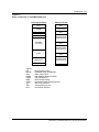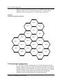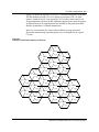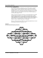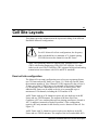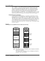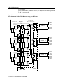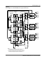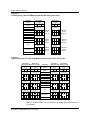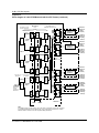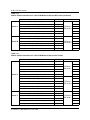
1
411-2021-111 Wireless Networks DualMode Metrocell Cell Site Description 411-2021-111 Standard 01.01 June 1996 Wireless Networks DualMode Metrocell Cell Site Description Product release: DualMode Metrocell Document release: Standard 01.01 Date: June 1996 Document Number: 411-2021-111 Copyright Country of printing Confidentiality Legal statements Trademarks 1996 Northern Telecom Printed in the United States of America NORTHERN TELECOM CONFIDENTIAL: The information contained in this document is the property of Northern Telecom. Except as specifically authorized in writing by Northern Telecom, the holder of this document shall keep the information contained herein confidential and shall protect same in whole or in part from disclosure and dissemination to third parties and use same for evaluation, operation, and maintenance purposes only. Information is subject to change without notice. DMS, DMS SuperNode, DMS-MSC, DMS-HLR, DMS-100, and MAP are trademarks of Northern Telecom. iv Publication history June 1996 Standard 01.01 Initial release of document. 411-2021-111 Standard 01.01 June 1996 v Contents Publication history iv About this document ix Intended audience for this publication ix How this publication is organized x Applicability of this publication x List of terms xi Introduction 1-1 Northern Telecom's DualMode Metrocell 1-1 The 800 MHz cellular band 1-4 Cell Site Configurations 2-1 Overview 2-1 Omni configuration 2-1 120° sectorized configuration 2-2 60° sectorized configuration 2-4 Cell Site Layouts 3-1 Omni cell site configuration 3-1 Control Channel redundancy 3-2 Transmit cabling 3-5 Receive cabling 3-7 Component requirement 3-7 120° STSR cell site configuration 3-8 Control Channel redundancy 3-8 Transmit cabling 3-12 Receive cabling 3-17 Component requirement 3-20 60° STSR cell site connection 3-21 Control Channel redundancy 3-21 Transmit cabling 3-27 Receive cabling 3-33 Component requirement 3-37 DMS-MTX DualMode Metrocell Cell Site Description vi Contents Cell Site Components 4-1 Customer Service Operations 4-3 Power and Grounding Requirements 5-1 Safety requirements 5-1 Power and grounding requirements 5-2 Frame power distribution 5-5 System power protection 5-6 Grounding 5-6 Cable Identification 5-9 Datafilling a Metro Cell Site 6-1 Datafill Overview 6-1 Table CLLI 6-2 Table ACUALM 6-2 Table VCHINV, CCHINV, LCRINV 6-5 Appendices Appendix A: DualMode Metrocell Cell Site Specifications 7-1 System Configuration 7-1 Radio Frequency 7-1 Audio Interface 7-2 Alarms 7-2 DC Power Requirements 7-3 Power Distribution Requirements 7-3 Mechanical 7-3 Packaging 7-4 Environmental 7-4 Regulatory 7-5 Appendix B: Frequency plans 7-7 N=7 Frequency plan (Band A) 7-7 N=7 Frequency plan (Band B) 7-8 N=4 Frequency plan (Band A) 7-9 N=4 Frequency plan (Band B) 7-9 List of figures Figure 1-1 Figure 1-2 Figure 1-3 Figure 1-4 Figure 2-1 Figure 2-2 Figure 2-3 Figure 3-1 Figure 3-2 Figure 3-3 System architecture of a DualMode Metrocell 1-2 Digital ready cellular product 1-2 Basic components of a DualMode Metrocell 1-3 Channel assignment for 800 MHz cellular systems 1-4 Omni (N=7) frequency reuse plan 2-2 120° (N=7) sectorized frequency reuse plan 2-3 60° (N=4) sectorized frequency reuse plan 2-4 Frame layout of an omni Metrocell with one RF frame (front view) 32 Block diagram of an omni Metrocell with up to 20 channels in one RF Frame 3-3 Block diagram of an omni Metrocell with 21 to 24 channels in one RF Frame 3-4 411-2021-111 Standard 01.01 June 1996 Contents vii Figure 3-4 Figure 3-5 Figure 3-6 Figure 3-7 Figure 3-8 Figure 3-9 Figure 3-10 Figure 3-11 Figure 5-1 Figure 6-1 Figure 6-2 Frame layout of a 120° STSR Metrocell site with one RF frame (front view) 3-9 Frame layout of a 120° STSR Metrocell site with three RF frames (front view) 3-9 Block diagram of a 120° STSR Metrocell using one RF Frame 3-10 Block diagram of a 120° STSR Metrocell using three RF Frames 311 Frame layout of a 60° STSR Metrocell with two RF frames (front view) 3-22 Typical frame layout of a 60° STSR Metrocell with four RF frames (front view) 3-22 Block diagram of a 60° STSR Metrocell with two RF Frames 3-23 Block diagram of a 60° STSR Metrocell with four RF Frames 3-25 Power distribution for the CE and RF Frames in a Metrocell 5-5 Example of Metro TRU datafill 6-6 Example of Metro ICRM/TRU hardwire configuration 6-7 List of tables Table 1-1 Table 3-1 Table 3-2 Table 3-3 Table 3-4 Table 3-5 Table 3-6 Table 3-7 Table 3-8 Table 3-9 Table 3-10 Table 3-11 Table 3-12 Table 3-13 Table 3-14 Table 3-15 Table 3-16 Table 3-17 Channel designation and frequency assignment 1-5 RF Frame 1 PA to ATC connection for an omni Metrocell with up to 20 channels 3-5 RF Frame 1 PA to ATC connection for an omni Metrocell with 21 channels or more 3-6 RMC to splitter connections for an Omni Metrocell 3-7 Component requirement for an omni Metrocell 3-7 PA to ATC connection for a 120° Metrocell with one RF Frame 3-12 PA to ATC connection for a 120° Metrocell with 20 channels or less per RF frame for one sector 3-13 PA to ATC connection for a 120° Metrocell with 21 channels or more per RF frame for one sector 3-15 RMC to splitter connections for a 120° STSR Metrocell with one RF Frame 3-17 RMC to splitter connections for a 120° STSR Metrocell with three RF Frames 3-18 Component requirement for a 120° STSR Metrocell with one RF Frame 3-20 Component requirement for a 120° STSR Metrocell with three RF Frames 3-20 PA to ATC connection for a 60° STSR Metrocell using two RF Frames 3-28 PA to ATC connection for a 60° STSR Metrocell using four RF Frames 3-30 RMC to splitter connections for a 60° STSR Metrocell with two RF Frames 3-33 RMC to splitter connections for a 60° STSR Metrocell with four RF Frames 3-34 Component requirement for a 60° STSR Metrocell with two RF Frames 3-37 Component requirement for a 60° STSR Metrocell with four RF Frames 3-37 DMS-MTX DualMode Metrocell Cell Site Description viii Contents Table 4-1 Table 5-1 Table 5-2 Table 6-1 Table 6-2 Table 6-3 Table 6-4 Table 6-5 Table 6-6 Major components of a DualMode Metrocell 4-1 Metrocell DC Power performance requirements 5-3 Cable identification - North America 5-9 Datafill differences of the Metrocell from an NT800DR cell 6-1 Trunk requirement for different Metrocell configurations 6-2 MTX Datafill Alarm Points for Metro RF Frame 6-3 MTX Alarm Points Datafill Numbers for Metro RF Frame 6-4 MTX Alarm Points Datafill Numbers for Metro CE Frame components 6-4 NT8X47BA Port Numbers for Metro TRU locations 6-5 411-2021-111 Standard 01.01 June 1996 ix About this document This publication is one of a set of documents that provide Northern Telecom (Nortel) customers with information and suggestions on the planning and maintenance of their DualMode Metrocell system. This set of documents includes the following manuals: • DualMode Metrocell Functional Description Manual — DualMode Metrocell Cell Site Description — DualMode Metrocell Common Equipment (CE) Frame Description — DualMode Metrocell Radio Frequency (RF) Frame Description • DualMode Metrocell Planning and Engineering Guidelines • DualMode Metrocell Installation Manual • DualMode Metrocell Operation and Maintenance Manual • DualMode Metrocell Troubleshooting Guidelines The manual suite for the DualMode Metrocell provides information on cell site configurations, hardware components, planning and installation procedures, as well as maintenance and troubleshooting methods. Intended audience for this publication The intended audience for this set of manuals is the cell site technicians and the planning engineers who require information in the maintenance and planning of a DualMode Metrocell. The Functional Description Manual provides a technical reference foundation for the other documents in the documentation suite and is written for all. The Planning and Engineering Guidelines is written for system planning personnel in implementing new cells or expanding existing cell sites in a cellular system. The Operation and Maintenance Manual and the Troubleshooting Guidelines that provide information on problem recognition and preventive maintenance are written for cell site technicians to assist them in troubleshooting and performing their routine work. DMS-MTX DualMode Metrocell Cell Site Description x About this document The document suite assumes that the reader possesses a basic knowledge of the cellular system and radio propagation and is familiar with measurement units incorporated in the system. Therefore, this document will not provide detailed information on the theory of switching and radio propagation. How this publication is organized This publication is organized to present the following information: • an introduction to the DualMode Metrocell Cell Site • the Metrocell cell site configurations; omni, 120° STSR and 60° STSR • the equipment layouts, block diagrams and transmit and receive cabling for each configuration • the cell site components required for each configuration • • the power and grounding requirements for a Metrocell cell site information on datafilling a Metrocell. Applicability of this publication This publication is generically applicable to MTX01 feature functionality, yet captures some BCS-independent environment and implementation issues. 411-2021-111 Standard 01.01 June 1996 xi List of terms A-Band The lower 333 channels (Channel 1 - 333) of the cellular band, normally assigned to a non-wireline operator in the US and Canada. The Expanded Spectrum provides 83 more channels, 50 (Channel 667 - 716) in the A’-Band and 33 (channel 991 - 1023) in the A"-Band. ACU Alarm Control Unit. A unit that provides discrete alarm monitoring, reporting and control functions at the cell site. It concentrates all alarm input points at the cell site and updates the MTX of any status change over redundant data links. AMPS Advanced Mobile Phone Service. Analog cellular phone service. ATC AutoTune Combiner. A cavity/isolator combiner featuring an automatic tuning system which monitors the transmitted RF and automatically tunes itself to that frequency. B-Band The upper 333 channels (Channel 334 - 666) of the cellular band, normally assigned to a wireline operator in the US and Canada. The Expanded Spectrum provides 83 more channels (Channel 717 - 799) in the B’-Band. BER Bit Error Rate. The ratio of error bits to the total number of transmitted bits. It is a measurement of quality of the digital connection. Carrier (RF) An unmodulated radio signal. Normally, it is a pure sine wave of steady frequency, amplitude, and phase. CCH Control Channel, sometimes referred to as the Signaling Channel which is always in use to enable call setup and registration. DMS-MTX DualMode Metrocell Cell Site Description xii List of terms Cell By theoretical design, it is the geographical representation of the cellular coverage area or service area defining both the associated size and shape. CSM2 Cell Site Monitor 2. A unit that provides analog testing and monitoring capabilities at the cell site. dBm Decibels above a milliwatt. Unit of power measurement popular in wireless telephony, general telephony, audio, and microwave. dBW Decibels above a watt. Unit of measurement for radio power DCC Digital Color Code. An identifying code associated with the control channel of the cellular base transmitter which is used to enhance call processing in the cellular infrastructure. DLR Digital Locate Receiver. The TDMA equivalent of the Locating Channel Receiver. See LCR. DMS-MTX The acronym for Nortel's family of cellular switches: Digital Multiplex Switch Mobile Transmission Exchange. DPA Dual Power Amplifier. A module which contains two discrete power amplifiers that provide amplification of the RF signal for the two corresponding Transmit Receive Units (TRU) on the same TRU/DPA shelf. DRUM DualMode Radio Unit Monitor. A test and monitor unit capable of radio communications with any Voice Channel of the local Transmit Receive Units (TRU) in the digital mode. Duplexer A device that consists of two pass or pass/reject filters configured to provide a common output port for both transmit and receive frequencies. DVCC Digital Verification Color Code. The TDMA equivalent of DCC. ES Expanded Spectrum. The additional frequency spectrum assigned to the cellular band. The Expanded Spectrum in the A-Band consists of the A’-Band and the A"Band while the B’-Band is the Expanded Spectrum for the B-Band. The Expanded Spectrum provides a total of 416 channels to each of the two bands. 411-2021-111 Standard 01.01 June 1996 List of terms xiii FDMA Frequency Division Multiple Access. A frequency assignment arrangement whereby all users share the total frequency allotment and each frequency is assigned to a given user at access on a multiple user access basis. Filter A frequency selective device which is tuned to pass some frequencies and attenuate others. Common filter types include high-pass, low pass, band-pass, and notch filters FM Frequency Modulation. A modulation technique that causes the frequency of the carrier to vary above and below its resting frequency; the rate of which is determined by the frequency of the modulating signal and the deviation of which is determined by the magnitude of the modulating signal. Forward path The path from cell site to cellular subscriber. HSMO High Stability Master Oscillator. A unit that provides a highly stable 4.8 MHz reference for synchronizing the Transmit Receive Unit (TRU). ICP Intelligent Cellular Peripheral. A switch site peripheral that provides an interface between the cell site and the switch. The ICP also oversees the operations of the cell site. ICRM Integrated Cellular Remote Module. A cell site peripheral that serves as an interface between the Intelligent Cellular Peripheral (ICP) and the radio transmission subsystems. The ICRM is designed to support both analog and digital Radio Frequency (RF) equipment. IM Intermodulation. A type of interaction between signals in a nonlinear medium which produces phantom signals at sum and difference frequencies. These phantom signals may interfere with reception of legitimate signals occupying the frequencies upon which they happen to fall. Isolation The attenuation (expressed in dB) between any two signal or radiation points. LCR Locating Channel Receiver. A radio receiver which is frequency agile and is used to measure and report the received signal strength, in dBm, of a channel. Loss A magnitude of attenuation, expressed in dB, for a given path between any two points. DMS-MTX DualMode Metrocell Cell Site Description xiv List of terms Modulation The process of placing information on an RF carrier. The modulation technique may involve changing the amplitude, frequency, or phase of the carrier determined by the modulation index. NES Non-expanded Spectrum. The frequency spectrum initially assigned to the cellular band. The Non-expanded Spectrum provides 333 channels to each of the two bands, the A-Band and the B-Band. Omni An antenna design which permits radiation in essentially all H-Plane azimuths. In cell sites, an Omni configuration means a single set of omni antennas is used for all channels. π/4 DQPSK Variation of Differential Quadrature Phase Shift Keying used in D_AMPS IS-54 TDMA for improved spectral characteristics and phase resolution. Permissible phase changes are integral multiples of π/4 radians (45 degrees). π/4 is used to reduce the peak to root mean square ratio requirements for linear PAs. Return loss A logarithmic relationship of the incident signal to the reflected signal as expressed, in dB, by the following relationship: Return Loss = 10 log Pr Pi where Pi = incident power in watts Pr = reflected power in watts The strength of the signal, expressed in dB, reflected by a load back into a transmission line due to impedance mismatch. -14 dB corresponds to a VSWR of 1.5:1. Reverse path The path from cellular subscriber terminal to cell site. RF Radio Frequency. Electromagnetic energy of the frequency range just above the audible frequencies and extending to visible light. RIP Rack Interface Panel. The RIP is the interface between the cell site power supply and the cell site equipment. 411-2021-111 Standard 01.01 June 1996 List of terms xv RMC Receive Multicoupler. A device for amplifying the input received from a single antenna and providing multiple outputs for a group of receivers. RSSI Received Signal Strength Indicator. A measurement of the received RF signal strength measured at the base station or the subscriber terminal. It is expressed in dBm. SAT Supervisory Audio Tone. A tone of 5970, 6000, or 6030 Hz which modulates the AMPS voice channel along with voice audio. It is generated by the cell site and is repeated by the mobile back to the cell site. The repeated SAT is checked by the cellular system to confirm the continuity of the complete RF path from the cell site to the subscriber terminal and back to the cell site. SCC SAT Color Code. The datafill values corresponding to the various SATs: 00 for 5970 Hz, 01 for 6000 Hz, 10 for 6030 Hz. Sector A theoretical wedge-shaped part of the coverage area of one cell site, served by a specific group of directional antennas on specific channels. Sectorization A cell site configuration that consists of two or more sectors in which a different control and voice channel assignment is given for each sector. In this arrangement, the datafill and channel assignments for each sector are tailored to meet the system operational requirements, providing more flexibility in the cell site configuration compared to an omni configuration but with a decrease in trunking efficiency. Signal (RF) Radio frequency energy associated with a particular or desired frequency. SINAD A standard measurement of detected audio quality that is related to signal-tonoise plus distortion of the RF signal strength at the receiver input terminal. 12 dB SINAD is the commonly used threshold for receiver sensitivity measurements to determine the weakest-practical analog RF input, in dBm, required by the receiver. A SINAD of 20 dB is considered good quality and defines the RF input level needed to fully quiet the receiver. S/N Signal-to-Noise ratio. The ratio of signal power to noise power on a radio channel. DMS-MTX DualMode Metrocell Cell Site Description xvi List of terms ST Signaling Tone. In AMPS cellular, a 10 kHz tone transmitted on the Reverse Voice Channel (RVC) as a precursor to messaging activity, and for certain callprocessing functions (acknowledgments, call termination). Presence of the tone mutes normal conversational audio. STSR Sectored-Transmit/Sectored-Receive. A cell configuration in which a different control and voice frequency assignment is designated for each sector. A directional antenna system is required for each sector. TDMA Time Division Multiple Access. A modulation and transmission format that allows a number of digital conversations (three in TDMA-3) to occur within the same Radio Frequency (RF) channel. Mobile units take turns transmitting/ receiving data on specific time slots of a TDMA frame. TRU Transmit Receive Unit. The TRU is a Digital Signal Processing (DSP) based transceiver capable of two modes of operation, analog (AMPS) and digital (TDMA). VCH Voice Channel. A Radio Frequency (RF) channel used to transmit cellular voice conversations. The VCH is also an integral part of call setup, handoff, and disconnect. VSWR Voltage Standing Wave Ratio. A measure of the mismatch between the transmitter source impedance and the load impedance to which it is connected. It is defined by the following relationship: 1+ Reflected Power Forward Power 1- Reflected Power Forward Power VSWR = 411-2021-111 Standard 01.01 June 1996 1-1 1 Introduction Northern Telecom's DualMode Metrocell As cellular systems evolve to the digital format, service providers and mobile subscribers are confronted by a mixture of analog and digital technologies. Northern Telecom (Nortel)’s dual mode cellular product allows a smooth transition from analog to digital technology. It uses Time Division Multiple Access (TDMA) technology for digital systems and Advanced Mobile Phone Service (AMPS) technology for analog systems. This evolutionary strategy enables service providers to gradually upgrade their cellular systems to digital while providing support of existing analog equipment. The Nortel cellular system supporting dual mode service includesthe following components: • the DMS-MTX switch containing the Intelligent Cellular Peripheral (ICP) unit at the mobile switching office • dual mode cell sites with the configurable DualMode Radio Units (DRU) on a Radio Frequency (RF) Frame and the Integrated Cellular Remote Module (ICRM), on a Common Equipment (CE) Frame at the cell site • external and internal interface links. The Nortel DualMode Metrocell serves as the intelligent interface between a Digital Multiplex Switch - Mobile Telephone Exchange (DMS-MTX) and its registered cellular mobiles. It is a dual mode cell that works in both the analog (AMPS) mode and the digital (TDMA) mode. The Metrocell is designed for high density, small radius cells in areas where large traffic capacity is required. It can exist independently or it can be added to existing cells for increased coverage. The Metrocell provides a reduced power output for urban applications. The typical power output of the Power Amplifier (PA) is 22 watts (43.5 dBm). Figure 1-1 shows the architecture of a DualMode Metrocell system and Figure 1-2 is a block diagram of the product of the system. DMS-MTX DualMode Metrocell Cell Site Description 1-2 Introduction Figure 1-1 System architecture of a DualMode Metrocell Trunk PSTN DMS-MTX Digital Transmission Facility DualMode Metrocell Figure 1-2 Digital ready cellular product DMS - MTX DRU voice & control voice and control ICP DRUM control ICRM CSM2 control ACU SWITCH SITE CELL SITE There are at least two equipment frames in a Metrocell, a Universal Common Equipment (CE) Frame and a Metro Radio Frequency (RF) Frame. The cell site can be expanded or sectorized by adding more Metro RF frames as traffic grows. The number of Metro RF frames is determined by the cell site configuration and the channel capacity. Figure 1-3 shows the frames and the components of a DualMode Metrocell. 411-2021-111 Standard 01.01 June 1996 Introduction 1-3 Figure 1-3 Basic components of a DualMode Metrocell Universal CE Frame RIP DRUM ACU HSMO CSM2 Dual RMC (one to six) Metro RF Frame RIP Duplexer (one to three) ATC TRU/DPA Shelf (TRUs & DPAs) ATC TRU/DPA Shelf (TRUs & DPAs) ICRM Legend: RIP DRUM ACU HSMO CSM2 RMC ICRM ATC TRU DPA ATC Blank Panel TRU/DPA Shelf (TRUs & DPAs) Base Base Rack Interface Panel DualMode Radio Unit Monitor Alarm Control Unit High Stability Master Oscillator Cell Site Monitor 2 Receive Multicoupler Integrated Cellular Remote Module AutoTune Combiner Transmit Receive Unit Dual Power Amplifier DMS-MTX DualMode Metrocell Cell Site Description 1-4 Introduction The 800 MHz cellular band In an 800 MHz North American cellular system, a frequency spectrum of 50 MHz is available for service. Operating from 824 to 894 MHz, including the expanded spectrum, the system conforms to the AMPS IS-54 protocol. Typically this range is divided into 832 radio frequency (RF) channels. The 832 RF channels are divided into two bands,A and B. The two bands are identified as follows: • Band A—for Non-Wireline Operators • Band B—for Wireline Operators. Each frequency band has 416 RF channels. Of these 416 RF channels, typically 21 (depending on the frequency plan) are assigned as the Control Channels (CCH) and the remaining 395 are Voice Channels (VCH). See Figure 1-4 and Table 1-1. Figure 1-4 Channel assignment for 800 MHz cellular systems RX 824 825 TX 869 870 Band A" Base Station Frequency (MHz) 835 A-Band CCH B-Band CCH 880 A 991 1 1023 B 333 Channel Number Channel assignment 835 846.5 890 891.5 A' 666 716 849 894 B' Band A (416 channels) Band B (416 channels) 313 - 333 (21) 334 - 354 (21) Optional—TDMA secondary control channels 688 - 708 (21) 737 - 757 (21) 001 - 312 (312) 667 - 716 (50) 991 - 1023 (33) 355 - 666 (312) 717 - 799 (83) 411-2021-111 Standard 01.01 June 1996 R 799 R=Reserved Control channels Voice channels 851 896 Introduction 1-5 Table 1-1 Channel designation and frequency assignment System Channel Cell site receive frequency (MHz) Cell site transmit frequency (MHz) Not used 990 824.010 869.010 A" 991 - 1023 824.040 - 825.000 869.040 - 870.000 A 1 - 333 825.030 - 834.990 870.030 - 879.990 B 334 - 666 835.020 - 844.980 880.020 - 889.980 A’ 667 - 716 845.010 - 846.480 890.010 - 891.480 B’ 717 - 799 846.510 - 848.970 891.510 - 893.970 The relationship between the channel number (N) and the frequency is: Channel number: 1 ≤ N ≤ 799 Receiver frequency (in MHz) = 0.03N + 825.000 Transmit frequency (in MHz) = 0.03N +870.000 Channel number: 990 ≤ N ≤ 1023 Receiver frequency (in MHz) = 0.03(N - 1023) + 825.000 Transmit frequency (in MHz) = 0.03(N - 1023) + 870.000 Both non-expanded and expanded spectrums are shown in Appendix B for the N=7 and N=4 frequency groups. Important For ALL Metrocell cell site configurations, the frequency plan used should have a minimum of 21 channel spacing (630 kHz) between the RF channels. DMS-MTX DualMode Metrocell Cell Site Description 1-6 Introduction 411-2021-111 Standard 01.01 June 1996 2-1 2 Cell Site Configurations Overview The DualMode Metrocell can be configured in the following ways: • Omni-directional transmit/receive • 120° Sectored Transmit Sectored Receive (STSR) • 60° Sectored Transmit Sectored Receive (STSR) The majority of systems may begin as Omni-directional to minimize startup costs. As the subscriber traffic increases, the Omni configuration may reach its maximum traffic capacity. At that time it will be necessary to provide additional capacity through expanded spectrum, 120 degree sectorization, 60 degree sectorization, or frequency borrowing. It is important that the operator selects a frequency plan before the Omni configuration is installed. If not, future expansions will be very difficult. The most common frequency plans are: • 7 Cell Cluster (N=7)—This frequency plan allows proper expansion from Omni to 120 degree sectorization (see Figure 2-1 and Figure 2-2). • 4 or 12 Cell Cluster (N=4 or N=12)—This frequency plan allows proper expansion from Omni to 60 degree sectorization (see Figure 2-3). Both non-expanded and expanded spectrums are shown in Appendix B for the N=7 and N=4 frequency groups. Omni configuration In an Omni (N=7) configuration, the 416 RF channels are divided among a group of seven cells (often known as a cluster). Each cell consists of a maximum of 59 or 60 RF channels (four cells with 59 channels and three cells with 60 channels, where three of the 59 or 60 channels are Control channels). The RF channels are reused by other cell clusters. Frequency reuse refers to the use of RF channels on the same carrier frequency in different areas which are separated from one another by the greatest possible distance so that cochannel interference is minimized. DMS-MTX DualMode Metrocell Cell Site Description 2-2 Cell Site Configurations Figure 2-1 shows the layout of an Omni (N=7) frequency reuse plan;. The RF channels used in Cell 1 of a cluster are reused in Cell 1 of other clusters, channels in Cell 2 are reused in Cell 2 of other clusters and so on. Figure 2-1 Omni (N=7) frequency reuse plan CELL 6 CELL 5 CELL 7 CELL 1 CELL 4 CELL 2 CELL 6 CELL 3 CELL 6 CELL 5 CELL 7 CELL 1 CELL 2 CELL 7 CELL 1 CELL 4 CELL 3 CELL 5 CELL 4 CELL 2 CELL 3 120° sectorized configuration In a 120° (N=7) sectorized configuration, the 416 RF channels are divided among a cluster of seven cells. Each cell contains a maximum of 59 or 60 RF channels, with three Control channels for each cell. Since each cell is further divided into three sectors, each sector will contain a maximum of 19 or 20 RF channels, with one Control channel for each sector. The available RF channels are reused by other groups of cells within the system. 411-2021-111 Standard 01.01 June 1996 Cell Site Configurations 2-3 Figure 2-2 shows the layout of a 120° (N=7) sectorized frequency reuse plan. The RF channels used in Cell 1 of a cluster are reused in Cell 1 of other clusters, channels in Cell 2 are reused in Cell 2 of other clusters and so on. This arrangement will have the RF channels using the same carrier frequency in different areas to be separated from one another by the greatest possible distance to minimize co-channel interference. However, sectorization (by virtue of the modified coverage areas and directional antenna usage) permits greater reuse of frequencies for a given C/I ratio. Figure 2-2 120° (N=7) sectorized frequency reuse plan Sector X Sector Z Sector X Sector Z Sector Y CELL 7 Sector Z Sector X Sector X Sector Z Sector X Sector Z Sector Y Sector Y Sector Z Sector X Sector X Sector CELL 2 Z Sector Y Sector Y Sector CELL 3 Z Sector Y Sector X Sector Z CELL 4 Sector Y CELL 3 Sector X Sector Y Sector CELL 6 Z Sector X Sector Y Sector Z Sector X Sector Z CELL 7 Sector X Sector Y Sector Z Sector X Sector Z CELL 5 Sector Y CELL 1 Sector Y CELL 2 Sector Y Sector X Sector Y Sector Y Sector CELL 4 Z Sector X CELL 5 Sector Y Sector X Sector Y Sector CELL 1 Z Sector X Sector Y Sector CELL 5 Z CELL 7 Sector Z CELL 1 CELL 2 CELL 6 Sector X Sector X Sector Y Sector Z CELL 6 Sector X Sector X Sector Z CELL 4 Sector Y Sector CELL 3 Z Sector Y DMS-MTX DualMode Metrocell Cell Site Description 2-4 Cell Site Configurations 60° sectorized configuration In a 60° (N=4) sectorized configuration, the 416 RF channels are divided among a group of four cells. Each cell contains a maximum of 104 RF channels, with six Control channels for each cell. Since each cell is further divided into six sectors, each sector will contain a maximum of 16 or 17 RF channels, with one Control channels for each sector. The RF channels are reused by other groups of cells. Figure 2-3 shows the layout of a 60° (N=4) sectorized frequency reuse plan. The RF channels used in Cell 1 of a cluster are reused in Cell 1 of other clusters, channels in Cell 2 are reused in Cell 2 of other clusters and so on. This arrangement will have the RF channels on the same carrier frequency in different areas to be separated from one another by the greatest possible distance so that co-channel interference is minimized. However, 60° sectorization is difficult to expand and optimize due to a more demanding environment of frequency re-use. Figure 2-3 60° (N=4) sectorized frequency reuse plan Sector W Sector X Sector CELL 2 Sector W Y Sector Sector Sector Sector X X Sector Sector Z Sector Sector V Y U W Y CELL 1 CELL 3 Sector Sector Sector Sector Sector Sector Sector X X X V Sector V Sector Sector Sector Sector Z Sector Sector Z Sector Y Y Y W U W U W CELL 2 CELL 2 CELL 4 Sector Sector Sector Sector Sector Sector Sector Sector Sector Sector X X V X Sector Sector X Sector Z Sector Z Sector Z Sector Sector Sector V Sector Sector V Sector Y W U W U W Y Y Y U W CELL 3 CELL 1 Sector V Sector U Sector Z CELL 1 Sector W Sector X CELL 4 Sector V CELL 3 Sector Sector Sector Sector Sector Sector Sector Sector X X Z V Sector V Sector Z Z V Sector Sector Sector Sector Sector Sector Y U W Y U U W Y CELL 4 CELL 2 Sector Sector Sector Sector Sector Sector Sector X X Sector Z Sector V Sector Z Sector Sector V Sector Z Sector U U W Y Y U W CELL 1 CELL 3 Sector Sector Sector Sector Sector X V Z V Sector Z Sector Sector Sector U Y U W CELL 4 Sector Sector V Sector Z U 411-2021-111 Standard 01.01 June 1996 3-1 3 Cell Site Layouts This chapter provides information on the layout and cabling of the different DualMode Metrocell configurations. Important For ALL Metrocell cell site configurations, the frequency plan used should have a minimum of 21 channel spacing (630 kHz) between the channels in one RF Frame. Note: The DualMode Metrocell supports only Transmit Receive Units (TRU) with Product Engineering Code (PEC) NTAX98AA. No other radios can be used. The NTAX98AA TRU supports full digital and analog transmissions in accordance with IS-54 and IS-41 standards. Omni cell site configuration The Metrocell in an omni configuration uses at least two equipment frames, one CE Frame and one RF frame (see Figure 3-1). With only one RF frame, the maximum number of Voice Channels (VCH) supported by the cell site is 22 since two of the 24 TRUs have to be assigned as the Control Channel (CCH) and the Locate Channel Receiver (LCR). As traffic grows, four additional RF frames can be added to the site to accommodate up to a maximum of 120 channels, including the CCH and the LCR. An RF Frame with up to 20 channels requires only one duplexer in the RF Frame and one TX/RX antenna. The outputs of the three AutoTune Combiners (ATC) are combined through one phasing transformer (located at ATC 2) and then connected to Duplexer position 2. This configuration requires a RX only antenna for the diversity receive function of the cell. See Figure 3-2. An RF Frame with 21 channels or more requires two duplexers in the RF Frame and two TX/RX antennas. The outputs of the lower and middle ATCs DMS-MTX DualMode Metrocell Cell Site Description 3-2 Cell Site Layouts (ATC 1 and ATC 2) are combined through one phasing transformer (located at ATC 2) and then connected to Duplexer position 2 and the main TX/RX Antenna. The output of the upper ATC (ATC 3) is connected to Duplexer position 3 and the diversity TX/RX Antenna. This arrangement is used to meet the requirement of a minimum of 21 channel spacing (630 kHz) between the channels in one RF Frame. This configuration requires a TX/RX antenna to perform the diversity receive function of the cell. See Figure 3-3. Control Channel redundancy Control Channel (CCH) redundancy is commonly provided with a Locate Channel Receiver (LCR) backup. The CCH is assigned to position 1 on the TRU/DPA Shelf 1 and the LCR is assigned to position 4 on the same shelf. This arrangement will have the CCH and the LCR supplied on a different DC power feed and a TCM card. No RF coaxial switch is required since the cavity of the LCR position on the ATC will tune to the CCH frequency when backup is required. Figure 3-1 Frame layout of an omni Metrocell with one RF frame (front view) CE Frame RF Frame 1 RF RIP CE RIP Duplexer Duplexer Duplexer TRU 19 TRU 23 TRU 20 TRU 24 TRU 11 TRU 15 TRU 12 TRU 16 TRU 9 TRU 13 TRU 10 TRU 14 ICRM Base DPA DPA 9 10 TRU/DPA Shelf 2 TRU/DPA Shelf 1 TRU/DPA Shelf 3 ATC 2 Blank Panel DPA DPA 7 8 DPA DPA 5 6 TRU 2 TRU 6 ATC 1 TRU 1 TRU 5 Blank Panel DPA DPA 11 12 TRU 3 TRU 7 ATC 3 TRU 4 TRU 8 ACU HSMO CSM2 RMC 1 TRU 18 TRU 22 Position 3 Position 2 Position 1 TRU 17 TRU 21 DRUM DPA DPA 3 4 DPA DPA 1 2 Base Note: For a frame with up to 20 channels, only one duplexer (located in position 2) is required. For a frame with 21 channels or more, two duplexers (located in positions 2 and 3) are required. 411-2021-111 Standard 01.01 June 1996 Cell Site Layouts 3-3 Figure 3-2 Block diagram of an omni Metrocell with up to 20 channels in one RF Frame RF Frame 1 DPA 5 TRU SHELF SPLITTER 4 DPA 4 TRU 8 654321 A8 B1 B2 B3 RMC 1B TRU/DPA Shelf 1 TRU 9 654321 ATC 1 TRU SHELF SPLITTER 1 DPA 1 TRU 1 654321 Control Channel (Note 2) A1 A2 A3 RMC 1A See Table 3-3 for RMC/TRU Shelf connection (Note 1) TX RX Antenna (Main receive) Duplexer ANT Position 2 Antenna (Diversity receive) B8 TRU 17 654321 TRU SHELF SPLITTER 4 TRU 16 654321 DPA 9 TRU SHELF SPLITTER 1 DPA 8 TRU/DPA Shelf 3 DPA 10 Notes: 1. For diagram clarity, only one RF Frame is shown. Other RF Frames with 20 channels or less are connected and operated identically to that of RF Frame 1. 2. TRU1 at TRU/DPA Shelf 1 of RF Frame 1 is assigned as the CCH and TRU4 at the same shelf is assigned as the backup CCH. TRU SHELF SPLITTER 4 ATC 3 TRU/DPA Shelf 2 TRU 20 654321 ATC 2 TRU SHELF SPLITTER 1 See Table 3-1 for PA/ATC connection CE Frame ICRM HSMO DMS-MTX DualMode Metrocell Cell Site Description 3-4 Cell Site Layouts Figure 3-3 Block diagram of an omni Metrocell with 21 to 24 channels in one RF Frame DPA 5 TRU SHELF SPLITTER 4 DPA 4 TRU 8 654321 TRU/DPA Shelf 1 TRU 9 654321 ATC 1 A1 A2 A3 A8 B1 B2 B3 RMC 1B DPA 1 TRU SHELF SPLITTER 1 Control Channel (Note 2) TRU 1 654321 (Note 1) RMC 1A See Table 3-3 for RMC/TRU Shelf connection RF Frame 1 B8 TX Antenna (Main receive) RX Duplexer ANT Position 2 TX RX Duplexer ANT Antenna (Diversity receive) Position 3 DPA 12 TRU SHELF SPLITTER 4 TRU 16 654321 DPA 9 Notes: 1. For diagram clarity, only one RF Frame is shown. Other RF Frames with 21 channels or mor are connected and operated identically to that of RF Frame 1. 2. TRU1 at TRU/DPA Shelf 1 of RF Frame 1 is assigned as the CCH and TRU4 at the same shelf is assigned as the backup CCH. TRU SHELF SPLITTER 1 DPA 8 TRU 17 654321 TRU/DPA Shelf 3 TRU SHELF SPLITTER 4 ATC 3 TRU/DPA Shelf 2 TRU 24 654321 ATC 2 TRU SHELF SPLITTER 1 See Table 3-2 for PA/ATC connection CE Frame ICRM HSMO 411-2021-111 Standard 01.01 June 1996 Cell Site Layouts 3-5 Transmit cabling In the transmit path, the output of each Transmit Receive Unit (TRU) is connected to the input of each corresponding power amplifier (PA) on the Dual Power Amplifier (DPA) module. The output of each power amplifier (PA) is input to an 8-channel AutoTune Combiner (ATC). The output of the ATC is connected to the Transmit (TX) port of the duplexer. For RF Frames using more than one ATC, the outputs of the ATCs are combined together and connected to the TX port of the duplexer. The duplexer serves as the interface between the antenna system and the RF frame. Table 3-1 lists the connection between the PAs and the ATC for an RF Frame with up to 20 channels. Table 3-2 lists the connection between the PAs and the ATC for an RF Frame with 21 channels or more. Table 3-1 RF Frame 1 PA to ATC connection for an omni Metrocell with up to 20 channels From TRU/DPA Shelf 1 TRU/DPA Shelf 2 TRU/DPA Shelf 3 Through DPA 1 - Port1 (CCH) ATC1 - Port 1 DPA 1 - Port2 ATC1 - Port 2 DPA 2 - Port1 ATC1 - Port 3 DPA 2 - Port2 (LCH) ATC Shelf 1 ATC1 - Port 4 DPA 3 - Port1 ATC1 - Port 5 DPA 3 - Port2 ATC1 - Port 6 DPA 4 - Port1 ATC1 - Port 7 DPA 4 - Port2 ATC1 - Port 8 DPA 5 - Port1 ATC2 - Port 1 DPA 5 - Port2 ATC2 - Port 2 DPA 6 - Port1 ATC2 - Port 3 DPA 6 - Port2 ATC Shelf 2 ATC2 - Port 5 DPA 7 - Port 2 ATC2 - Port 6 DPA 8 - Port1 ATC2 - Port 7 DPA 8 - Port 2 ATC2 - Port 8 DPA 9 - Port1 ATC3 - Port 1 ATC Shelf 3 Duplexer Position 2 Antenna (Main receive) ATC2 - Port 4 DPA 7 - Port1 DPA 9 - Port 2 To ATC3 - Port 2 DPA 10 - Port1 ATC3 - Port 3 DPA 10 - Port2 ATC3 - Port 4 Note: Additional RF Frames with 20 channels or less are connected to their respective TX/RX antennas in the same way as RF Frame 1. DMS-MTX DualMode Metrocell Cell Site Description 3-6 Cell Site Layouts Table 3-2 RF Frame 1 PA to ATC connection for an omni Metrocell with 21 channels or more From TRU/DPA Shelf 1 TRU/DPA Shelf 2 TRU/DPA Shelf 3 Through DPA 1 - Port1 (CCH) ATC1 - Port 1 DPA 1 - Port2 ATC1 - Port 2 DPA 2 - Port1 ATC1 - Port 3 DPA 2 - Port2 (LCH) ATC Shelf 1 ATC1 - Port 4 DPA 3 - Port1 ATC1 - Port 5 DPA 3 - Port2 ATC1 - Port 6 DPA 4 - Port1 ATC1 - Port 7 DPA 4 - Port2 ATC1 - Port 8 DPA 5 - Port1 ATC2 - Port 1 DPA 5 - Port2 ATC2 - Port 2 DPA 6 - Port1 ATC2 - Port 3 DPA 6 - Port2 ATC Shelf 2 ATC2 - Port 5 DPA 7 - Port 2 ATC2 - Port 6 DPA 8 - Port1 ATC2 - Port 7 DPA 8 - Port 2 ATC2 - Port 8 DPA 9 - Port1 ATC3 - Port 1 DPA 9 - Port 2 ATC3 - Port 2 DPA 10 - Port1 ATC3 - Port 3 ATC Shelf 3 Duplexer Position 2 Antenna (Main receive) Duplexer Position 3 Antenna (Diversity receive) ATC2 - Port 4 DPA 7 - Port1 DPA 10 - Port2 To ATC3 - Port 4 DPA 11 - Port1 ATC3 - Port 5 DPA 11 - Port 2 ATC3 - Port 6 DPA 12 - Port1 ATC3 - Port 7 DPA 12 - Port2 ATC3 - Port 8 Note: Additional RF Frames with 21 channels or more are connected to their respective TX/RX antennas in the same way as RF Frame 1. 411-2021-111 Standard 01.01 June 1996 Cell Site Layouts 3-7 Receive cabling In the reverse path, the receive signal from the main antenna is connected to the A-input of the Receive Multicoupler (RMC) through the receive port of the duplexer. The diversity antenna connects directly to the B-input of the RMC. Distribution of the reverse path frequencies is accomplished by RF splitters within each RF frame. Table 3-3 shows the connection between the RMC and the splitters. Table 3-3 RMC to splitter connections for an Omni Metrocell From Through To Main antenna RMC 1A - A1 TRU Shelf 1 Splitter 1 Diversity antenna RMC 1B - B1 TRU Shelf 1 Splitter 4 Main antenna RMC 1A - A2 TRU Shelf 2 Splitter 1 Diversity antenna RMC 1B - B2 TRU Shelf 2 Splitter 4 Main antenna RMC 1A - A3 TRU Shelf 3 Splitter 1 Diversity antenna RMC 1B - B3 TRU Shelf 3 Splitter 4 Component requirement Table 3-4 lists the components required for a Metrocell with one to five RF Frames. An omni cell site requires only one Receive Multicoupler (RMC). Table 3-4 Component requirement for an omni Metrocell Configuration with up to 20 channels per RF Frame Configuration with up to 24 channels per RF Frame No. of RF Frames No. of TRUs No. of ATCs Duplexer per frame ICRM TCM Port cards No. of antennas 1 3 to 20 1 to 3 1 2 1 TX/RX, 1 RX 2 21 to 40 4 to 6 1 4 2 TX/RX 3 41 to 60 7 to 9 1 6 2 TX/RX, 1 TX 4 61 to 80 10 to 12 1 6 2 TX/RX, 2 TX 5 81 to 100 13 to 15 1 8 2 TX/RX, 3 TX 1 3 to 24 1 to 3 2 2 2 TX/RX 2 25 to 48 4 to 6 2 4 2 TX/RX, 2 TX 3 49 to 72 7 to 9 2 6 2 TX/RX, 4 TX 4 73 to 96 10 to 12 2 6 2 TX/RX, 6 TX 5 97 to 120 13 to 15 2 8 2 TX/RX, 8 TX Note: An additional TCM port card is required for the DRUM, the ACU and the CSM2. DMS-MTX DualMode Metrocell Cell Site Description 3-8 Cell Site Layouts 120° STSR cell site configuration The Metrocell in a 120° STSR configuration uses at least two equipment frames, one CE Frame and one RF frame (see Figure 3-4). Each TRU/DPA Shelf and its associated ATC on the RF frame support one of the three sectors. With only one RF frame, the maximum number of Voice Channels (VCH) supported by each sector is six since two of the eight TRUs on the TRU shelf have to be assigned as the Control Channel (CCH) and the Locate Channel Receiver (LCR). A 120° STSR Metrocell with one RF Frame requires six antennas; one TX/RX antenna and one RX only antenna for each sector (see Figure 3-6). As traffic grows, two additional RF frames can be added to accommodate more VCHs (see Figure 3-5). A 120° STSR Metrocell with three RF Frames requires six antennas. It may be three TX/RX antennas and three RX only antennas or six TX/RX antennas depending on the number of channels in each RF Frame. An RF Frame with 20 channels or less in one sector requires one duplexer in the RF Frame and one TX/RX antennas for that sector. The outputs of the three combiners are combined through one phasing transformer (located at ATC 2) and connected to Duplexer position 2 in that RF Frame. The output of the duplexer is then connected to the main TX/RX Antenna of that sector). An RF Frame with 21 channels or more in one sector requires two duplexers in the RF Frame and two TX/RX antennas for that sector. The outputs of A TC 1 and ATC 2 are combined through one phasing transformer (located at ATC 2) and connected to Duplexer position 2 in that RF Frame. The output of the duplexer is then connected to main TX/RX Antenna of that sector. The output of ATC 3 is connected to Duplexer position 3 and then to the diversity TX/RX Antenna of that sector. This arrangement is used to meet the requirement of a minimum of 21 channel spacing (630 kHz) between the channels in one RF Frame. Figure 3-5 shows the frame layout and Figure 3-7 shows the block diagram of a 120° STSR Metrocell with three RF Frames. Control Channel redundancy Control Channel (CCH) redundancy is commonly provided with a Locate Channel Receiver (LCR) backup. With one RF Frame, the CCH of each sector is assigned to position 1 on the TRU/DPA Shelf of that sector and the LCR is assigned to position 4 on the same shelf. With three RF Frames, the CCH of each sector is assigned to position 1 on TRU/DPA Shelf 1 of that sector and the LCR is assigned to position 4 on the same shelf. This arrangement will have the CCH and the LCR supplied on a different DC power feed and a TCM card. No RF coaxial switch is required since the cavity of the LCR position on the ATC will tune to the CCH frequency when backup is required. 411-2021-111 Standard 01.01 June 1996 Cell Site Layouts 3-9 Figure 3-4 Frame layout of a 120° STSR Metrocell site with one RF frame (front view) CE Frame RF Frame 1 CE RIP RF RIP DRUM Duplexer Duplexer Duplexer Position 3 Position 2 Position 1 (Sector Z) (Sector Y) (Sector X) TRU 19 TRU 23 TRU 20 TRU 24 DPA DPA 9 10 TRU 11 TRU 15 RMC 2 (Sector Y) RMC 3 (Sector Z) TRU/DPA Shelf 3 (Sector Z) TRU 12 TRU 16 RMC 1 (Sector X) DPA DPA 11 12 TRU/DPA Shelf 2 (Sector Y) TRU 4 TRU 8 TRU 18 TRU 22 TRU 17 TRU 21 HSMO CSM 2 TRU 3 TRU 7 ATC 3 (Sector Z) ACU TRU/DPA Shelf 1 (Sector X) TRU 9 TRU 13 Blank Panel TRU 10 TRU 14 ATC 2 (Sector Y) ICRM DPA DPA 7 8 DPA DPA 5 6 Blank Panel Base TRU 2 TRU 6 TRU 1 TRU 5 ATC 1 (Sector X) DPA DPA 3 4 DPA DPA 1 2 Base Figure 3-5 Frame layout of a 120° STSR Metrocell site with three RF frames (front view) RF Frame 1 (Sector X) CE Frame RF Frame 2 (Sector Y) RF RIP CE RIP Duplexer Duplexer RF Frame 3 (Sector Z) RF RIP Duplexer Duplexer RF RIP Duplexer Duplexer Duplexer Duplexer Duplexe Base Base Base TRU 19 TRU 23 TRU 20 TRU 24 TRU 11 TRU 15 TRU 12 TRU 16 TRU/DPA Shelf 2 TRU 4 TRU 8 TRU 2 TRU 6 TRU 1 TRU 5 DPA DPA 1 2 TRU/DPA Shelf 3 DPA DPA 7 8 DPA DPA 5 6 TRU/DPA Shelf 1 ATC 1 TRU 4 TRU 8 DPA DPA 3 4 DPA DPA 9 10 TRU 3 TRU 7 TRU 18 TRU 22 TRU 17 TRU 21 TRU 9 TRU 13 TRU 10 TRU 14 TRU 12 TRU 16 DPA DPA 5 6 TRU 11 TRU 15 TRU 9 TRU 13 TRU 11 TRU 15 TRU 12 TRU 16 TRU 10 TRU 14 TRU 2 TRU 6 DPA DPA 1 2 TRU 1 TRU 5 DPA DPA 3 4 DPA DPA 7 8 DPA DPA 11 12 ATC 2 ATC 1 TRU 4 TRU 8 TRU 2 TRU 6 ATC 1 TRU 1 TRU 5 Blank Panel DPA DPA 5 6 DPA DPA 9 10 TRU 3 TRU 7 ICRM DPA DPA 7 8 DPA DPA 11 12 ATC 2 TRU 3 TRU 7 Blank Panel DPA DPA 9 10 ATC 2 TRU 9 TRU 13 RMC 2 (Sector Y) RMC 3 (Sector Z) TRU 10 TRU 14 RMC 1 (Sector X) DPA DPA 11 12 TRU 19 TRU 23 ATC 3 TRU 20 TRU 24 ATC 3 TRU 18 TRU 22 ATC 3 TRU 17 TRU 21 ACU HSMO CSM 2 TRU 19 TRU 23 Position 3 Position 2 Position 1 TRU 20 TRU 24 Position 3 Position 2 Position 1 TRU 18 TRU 22 Position 3 Position 2 Position 1 TRU 17 TRU 21 DRUM DPA DPA 3 4 DPA DPA 1 2 Base Note: For a frame with up to 20 channels, only one duplexer (located in position DMS-MTX DualMode Metrocell Cell Site Description 3-10 Cell Site Layouts 2) is required. For a frame with 21 channels or more, two duplexers (located in positions 2 and 3) are required. Figure 3-6 Block diagram of a 120° STSR Metrocell using one RF Frame A8 B1 B2 B3 RMC 1A A1 A2 A3 TX RX Duplexer ANT Position 1 Antenna (Sector X Main receive) Antenna (Sector X Diversity receive) RMC 1B TRU/DPA Shelf 1 DPA 5 TRU SHELF SPLITTER 1 TRU 9 654321 Control Channel for Sector Y TRU/DPA Shelf 2 A1 A2 A3 A8 B1 B2 B3 RMC 2A TRU 8 654321 TRU SHELF SPLITTER 6 B8 DPA 4 ATC 2 TRU SHELF SPLITTER 1 DPA 1 TRU 1 654321 Control Channel for Sector X ATC 1 See Table 3-8 for RMC/TRU Shelf connection RF Frame 1 TX RX Duplexer ANT Position 2 Antenna (Sector Y Main receive) Antenna (Sector Y Diversity receive) RMC 2B See Table 3-5 for PA/ATC connection TRU/DPA Shelf 3 A8 B1 B2 B3 RMC 3A A1 A2 A3 RMC 3B ATC 3 TRU SHELF SPLITTER 6 TRU 16 654321 DPA 9 Control Channel for Sector Z TRU SHELF SPLITTER 1 DPA 8 TRU 17 654321 B8 TRU 24 654321 DPA 12 TRU SHELF SPLITTER 6 B8 CE Frame ICRM HSMO 411-2021-111 Standard 01.01 June 1996 TX RX Duplexer ANT Position 3 Antenna (Sector Z Main receive) Antenna (Sector Z Diversity receive) Cell Site Layouts 3-11 Figure 3-7 Block diagram of a 120° STSR Metrocell using three RF Frames TRU/DPA Shelf 1 TX RX RX Antenna (Sector X Diversity receive) Note 2 A8 B1 B2 B3 TRU/DPA Shelf 2 RMC 2A TRU 9 654321 Duplexer ANT Position 3 Antenna (Sector X Main receive) TRU SHELF SPLITTER 6 TRU 8 654321 DPA 5 A1 A2 A3 TRU SHELF SPLITTER 1 DPA 4 Duplexer ANT Position 2 TX B8 TX RX Duplexer ANT Position 2 RF Frame 2 RMC 2B ATC 2 A8 B1 B2 B3 RMC 1A TRU 1 654321 DPA 1 A1 A2 A3 RMC 1B Note 1 Control Channel for Sector X ATC 1 See Table 3-9 for RMC/TRU Shelf connection RF Frame 1 TRU SHELF SPLITTER 1 See Tables 3-6 and 3-7 for PA/ATC connection TX RX Duplexer ANT Position 3 Antenna (Sector Y Main receive) Antenna (Sector Y Diversity receive) A1 A2 A3 A8 B1 B2 B3 TRU/DPA Shelf 3 RMC 3A TRU SHELF SPLITTER 1 DPA 9 TX RX Duplexer ANT Position 2 RF Frame 3 RMC 3B TRU 16 654321 TRU 17 654321 DPA 8 ATC 3 TRU SHELF SPLITTER 6 B8 TX RX Duplexer ANT Position 3 Antenna (Sector Z Main receive) Antenna (Sector Z Diversity receive) TRU 24 654321 DPA 12 TRU SHELF SPLITTER 6 B8 CE Frame ICRM HSMO Notes: 1. For diagram clarity, only RF Frame 1 is shown. RF Frames 2 and 3 are connected and operated identically to that of RF Frame 1. 2. For RF Frames with 20 channels or less, the Duplexer in position 3 is not required. The outputs of the three ATCs are combined together and connected to the Duplexer in position 2. See Table 3-6. DMS-MTX DualMode Metrocell Cell Site Description 3-12 Cell Site Layouts Transmit cabling In the transmit path, the output of each Transmit Receive Unit (TRU) is connected to the input of each corresponding power amplifier (PA) on the Dual Power Amplifier (DPA) module. For a 120° STSR cell site with one RF Frame, each TRU/DPA Shelf and its associated ATC and duplexer serve for one of the three sectors; TRU/DPA Shelf 1, ATC 1 and Duplexer 1 for Sector X, TRU/DPA Shelf 2, ATC 2 and Duplexer 2 for Sector Y and TRU/DPA Shelf 3, ATC 3 and Duplexer 3 for Sector Z. The output of each power amplifier (PA) is input to an 8-channel AutoTune Combiner (ATC). The output of each 8-channel ATC is connected to the Transmit (TX) port of each corresponding duplexer. Table 3-5 lists the connection between the PAs and the ATC for a 120° STSR cell site using one RF Frame for three sectors. For a 120° STSR cell site with three RF Frames, each frame serves for one of the three sectors; RF Frame 1 for Sector X, RF Frame 2 for Sector Y and RF Frame 3 for Sector Z. With an RF Frame holding up to 20 channels, only one duplexer is required. With 21 or more channels in one RF Frame, two duplexers are required. Table 3-6 lists the connection between the PAs and the ATC for an RF Frame with up to 20 channels. Table 3-7 lists the connection between the PAs and the ATC for an RF Frame with 21 channels or more. Table 3-5 PA to ATC connection for a 120° Metrocell with one RF Frame From TRU/DPA Shelf 1 TRU/DPA Shelf 2 Through DPA 1 - Port1 (CCH) ATC1 - Port 1 DPA 1 - Port2 ATC1 - Port 2 DPA 2 - Port1 ATC1 - Port 3 DPA 2 - Port2 (LCR) ATC Shelf 1 ATC1 - Port 4 DPA 3 - Port1 ATC1 - Port 5 DPA 3 - Port2 ATC1 - Port 6 DPA 4 - Port1 ATC1 - Port 7 DPA 4 - Port2 ATC1 - Port 8 DPA 5 - Port1 (CCH) ATC2 - Port 1 DPA 5 - Port2 ATC2 - Port 2 DPA 6 - Port1 ATC2 - Port 3 DPA 6 - Port2 (LCR) ATC Shelf 2 ATC2 - Port 4 DPA 7 - Port1 ATC2 - Port 5 DPA 7 - Port 2 ATC2 - Port 6 DPA 8 - Port1 ATC2 - Port 7 DPA 8 - Port 2 ATC2 - Port 8 411-2021-111 Standard 01.01 June 1996 To Duplexer Position 1 Antenna (Main receive for Sector X) Duplexer Position 2 Antenna (Main receive for Sector Y) Cell Site Layouts 3-13 Table 3-5 PA to ATC connection for a 120° Metrocell with one RF Frame (continued) From TRU/DPA Shelf 3 Through DPA 9 - Port1 (CCH) ATC3 - Port 1 DPA 9 - Port 2 ATC3 - Port 2 DPA 10 - Port1 ATC3 - Port 3 DPA 10 - Port2 (LCR) ATC Shelf 3 ATC3 - Port 4 DPA 11 - Port1 ATC3 - Port 5 DPA 11 - Port2 ATC3 - Port 6 DPA 12 - Port1 ATC3 - Port 7 DPA 12 - Port2 ATC3 - Port 8 To Duplexer Position 3 Antenna (Main receive for Sector Z) Table 3-6 PA to ATC connection for a 120° Metrocell with 20 channels or less per RF frame for one sector From Through DPA 1 - Port1 (CCH) ATC1 - Port 1 DPA 1 - Port2 ATC1 - Port 2 RF Frame 1 DPA 2 - Port1 TRU/DPA DPA 2 - Port2 (LCR) Shelf 1 DPA 3 - Port1 ATC1 - Port 3 RF Frame 1 ATC Shelf 1 ATC1 - Port 4 ATC1 - Port 5 DPA 3 - Port2 ATC1 - Port 6 DPA 4 - Port1 ATC1 - Port 7 DPA 4 - Port2 ATC1 - Port 8 DPA 5 - Port1 ATC2 - Port 1 DPA 5 - Port2 ATC2 - Port 2 RF Frame 1 DPA 6 - Port1 TRU/DPA DPA 6 - Port2 Shelf 2 DPA 7 - Port1 ATC2 - Port 3 RF Frame 1 ATC Shelf 2 Antenna (Main receive for Sector X) ATC2 - Port 5 ATC2 - Port 6 DPA 8 - Port1 ATC2 - Port 7 DPA 8 - Port 2 ATC2 - Port 8 DPA 9 - Port1 ATC3 - Port 1 RF Frame 1 ATC Shelf 3 RF Frame 1 Duplexer Position 2 ATC2 - Port 4 DPA 7 - Port 2 RF Frame 1 DPA 9 - Port 2 TRU/DPA DPA 10 - Port1 Shelf 3 DPA 10 - Port2 To ATC3 - Port 2 ATC3 - Port 3 ATC3 - Port 4 DMS-MTX DualMode Metrocell Cell Site Description 3-14 Cell Site Layouts Table 3-6 PA to ATC connection for a 120° Metrocell with 20 channels or less per RF frame for one sector (continued) From Through To DPA 1 - Port1 (CCH) ATC1 - Port 1 DPA 1 - Port2 ATC1 - Port 2 DPA 2 - Port1 ATC1 - Port 3 RF Frame 2 DPA 2 - Port2 (LCR) TRU/DPA DPA 3 - Port1 Shelf 1 DPA 3 - Port2 RF Frame 2 ATC Shelf 1 ATC1 - Port 4 ATC1 - Port 5 ATC1 - Port 6 DPA 4 - Port1 ATC1 - Port 7 DPA 4 - Port2 ATC1 - Port 8 DPA 5 - Port1 ATC2 - Port 1 DPA 5 - Port2 ATC2 - Port 2 DPA 6 - Port1 ATC2 - Port 3 RF Frame 2 DPA 6 - Port2 TRU/DPA DPA 7 - Port1 Shelf 2 DPA 7 - Port 2 RF Frame 2 ATC Shelf 2 ATC2 - Port 4 DPA 8 - Port 2 ATC2 - Port 8 DPA 9 - Port1 ATC3 - Port 1 RF Frame 2 ATC Shelf 3 Antenna (Main receive for Sector Z) ATC3 - Port 2 ATC3 - Port 3 ATC3 - Port 4 DPA 1 - Port1 (CCH) ATC1 - Port 1 DPA 1 - Port2 ATC1 - Port 2 DPA 2 - Port1 ATC1 - Port 3 RF Frame 3 ATC Shelf 1 ATC1 - Port 4 ATC1 - Port 5 ATC1 - Port 6 DPA 4 - Port1 ATC1 - Port 7 DPA 4 - Port2 ATC1 - Port 8 DPA 5 - Port1 ATC2 - Port 1 DPA 5 - Port2 ATC2 - Port 2 RF Frame 3 DPA 6 - Port1 TRU/DPA DPA 6 - Port2 Shelf 2 DPA 7 - Port1 RF Frame 3 Duplexer Position 2 ATC2 - Port 6 ATC2 - Port 7 RF Frame 3 DPA 2 - Port2 (LCR) TRU/DPA DPA 3 - Port1 Shelf 1 DPA 3 - Port2 Antenna (Main receive for Sector Y) ATC2 - Port 5 DPA 8 - Port1 RF Frame 2 DPA 9 - Port 2 TRU/DPA DPA 10 - Port1 Shelf 3 DPA 10 - Port2 RF Frame 2 Duplexer Position 2 RF Frame 3 ATC Shelf 2 DPA 7 - Port 2 411-2021-111 Standard 01.01 June 1996 ATC2 - Port 3 ATC2 - Port 4 ATC2 - Port 5 ATC2 - Port 6 Cell Site Layouts 3-15 Table 3-6 PA to ATC connection for a 120° Metrocell with 20 channels or less per RF frame for one sector (continued) From Through To RF Frame 3 DPA 8 - Port1 TRU/DPA DPA 8 - Port 2 Shelf 2 RF Frame 3 ATC 2 DPA 9 - Port1 RF Frame 3 DPA 9 - Port 2 TRU/DPA DPA 10 - Port1 Shelf 3 DPA 10 - Port2 ATC2 - Port 7 ATC2 - Port 8 ATC3 - Port 1 RF Frame 3 ATC Shelf 3 ATC3 - Port 2 ATC3 - Port 3 RF Frame 3 Duplexer Position 2 Antenna (Main receive for Sector Z) ATC3 - Port 4 Table 3-7 PA to ATC connection for a 120° Metrocell with 21 channels or more per RF frame for one sector From Through DPA 1 - Port1 (CCH) ATC1 - Port 1 DPA 1 - Port2 ATC1 - Port 2 DPA 2 - Port1 ATC1 - Port 3 RF Frame 1 DPA 2 - Port2 (LCR) TRU/DPA DPA 3 - Port1 Shelf 1 DPA 3 - Port2 RF Frame 1 ATC Shelf 1 ATC1 - Port 4 ATC1 - Port 5 ATC1 - Port 6 DPA 4 - Port1 ATC1 - Port 7 DPA 4 - Port2 ATC1 - Port 8 DPA 5 - Port1 ATC2 - Port 1 DPA 5 - Port2 ATC2 - Port 2 DPA 6 - Port1 ATC2 - Port 3 RF Frame 1 DPA 6 - Port2 TRU/DPA DPA 7 - Port1 Shelf 2 DPA 7 - Port 2 RF Frame 1 ATC Shelf 2 RF Frame 1 Duplexer Position 2 Antenna (Main receive for Sector X) RF Frame 1 Duplexer Position 3 Antenna (Diversity receive for Sector X) ATC2 - Port 4 ATC2 - Port 5 ATC2 - Port 6 DPA 8 - Port1 ATC2 - Port 7 DPA 8 - Port 2 ATC2 - Port 8 DPA 9 - Port1 ATC3 - Port 1 DPA 9 - Port 2 ATC3 - Port 2 DPA 10 - Port1 ATC3 - Port 3 RF Frame 1 DPA 10 - Port2 TRU/DPA DPA 11- Port1 Shelf 3 DPA 11- Port 2 To RF Frame 1 ATC Shelf 3 ATC3 - Port 4 ATC3 - Port 5 ATC3 - Port 6 DPA 12 - Port1 ATC3 - Port 7 DPA 12 - Port2 ATC3 - Port 8 DMS-MTX DualMode Metrocell Cell Site Description 3-16 Cell Site Layouts Table 3-7 PA to ATC connection for a 120° Metrocell with 21 channels or more per RF frame for one sector (continued) From Through To DPA 1 - Port1 (CCH) ATC1 - Port 1 DPA 1 - Port2 ATC1 - Port 2 DPA 2 - Port1 ATC1 - Port 3 RF Frame 2 DPA 2 - Port2 (LCR) TRU/DPA DPA 3 - Port1 Shelf 1 DPA 3 - Port2 RF Frame 2 ATC Shelf 1 ATC1 - Port 4 ATC1 - Port 5 ATC1 - Port 6 DPA 4 - Port1 ATC1 - Port 7 DPA 4 - Port2 ATC1 - Port 8 DPA 5 - Port1 ATC2 - Port 1 DPA 5 - Port2 ATC2 - Port 2 DPA 6 - Port1 ATC2 - Port 3 RF Frame 2 DPA 6 - Port2 TRU/DPA DPA 7 - Port1 Shelf 2 DPA 7 - Port 2 RF Frame 2 ATC Shelf 2 Antenna (Diversity receive for Sector Y) RF Frame 3 Duplexer Position 2 Antenna (Main receive for Sector Z) ATC2 - Port 6 DPA 8 - Port 2 ATC2 - Port 8 DPA 9 - Port1 ATC3 - Port 1 DPA 9 - Port 2 ATC3 - Port 2 DPA 10 - Port1 ATC3 - Port 3 RF Frame 2 ATC Shelf 3 ATC3 - Port 4 ATC3 - Port 5 ATC3 - Port 6 DPA 12 - Port1 ATC3 - Port 7 DPA 12 - Port2 ATC3 - Port 8 DPA 1 - Port1 (CCH) ATC1 - Port 1 DPA 1 - Port2 ATC1 - Port 2 DPA 2 - Port1 ATC1 - Port 3 RF Frame 3 ATC Shelf 1 ATC1 - Port 4 ATC1 - Port 5 ATC1 - Port 6 DPA 4 - Port1 ATC1 - Port 7 DPA 4 - Port2 ATC1 - Port 8 RF Frame 3 DPA 5 - Port1 TRU/DPA DPA 5 - Port2 Shelf 2 DPA 6 - Port1 RF Frame 2 Duplexer Position 3 ATC2 - Port 5 ATC2 - Port 7 RF Frame 3 DPA 2 - Port2 (LCR) TRU/DPA DPA 3 - Port1 Shelf 1 DPA 3 - Port2 Antenna (Main receive for Sector Y) ATC2 - Port 4 DPA 8 - Port1 RF Frame 2 DPA 10 - Port2 TRU/DPA DPA 11- Port1 Shelf 3 DPA 11- Port 2 RF Frame 2 Duplexer Position 2 RF Frame 3 ATC Shelf 2 411-2021-111 Standard 01.01 June 1996 ATC2 - Port 1 ATC2 - Port 2 ATC2 - Port 3 Cell Site Layouts 3-17 Table 3-7 PA to ATC connection for a 120° Metrocell with 21 channels or more per RF frame for one sector (continued) From Through To RF Frame 3 DPA 6 - Port2 TRU/DPA DPA 7 - Port1 Shelf 2 DPA 7 - Port 2 RF Frame 3 ATC Shelf 2 ATC2 - Port 4 ATC2 - Port 5 ATC2 - Port 6 DPA 8 - Port1 ATC2 - Port 7 DPA 8 - Port 2 ATC2 - Port 8 DPA 9 - Port1 ATC3 - Port 1 DPA 9 - Port 2 ATC3 - Port 2 DPA 10 - Port1 ATC3 - Port 3 RF Frame 3 DPA 10 - Port2 TRU/DPA DPA 11- Port1 Shelf 3 DPA 11- Port 2 RF Frame 3 ATC Shelf 3 ATC3 - Port 4 ATC3 - Port 5 ATC3 - Port 6 DPA 12 - Port1 ATC3 - Port 7 DPA 12 - Port2 ATC3 - Port 8 RF Frame 3 Duplexer Position 2 Antenna (Main receive for Sector Z) RF Frame 3 Duplexer Position 3 Antenna (Diversity receive for Sector Z) Receive cabling In the reverse path, the receive signal from the main antenna of each sector is connected to the A-input of the Receive Multicoupler (RMC) through the receive port of the duplexer of that sector. The diversity antenna connects directly to the B-input of the RMC. Distribution of the reverse path frequencies is accomplished by RF splitters within each RF frame. Table 3-8 lists the connection between the RMCs and the RF splitters in a 120° STSR Metrocell with one RF Frame. Table 3-9 lists the connection between the RMCs and the RF splitters in a 120° STSR Metrocell using three RF frames. Table 3-8 RMC to splitter connections for a 120° STSR Metrocell with one RF Frame From Sector X Through To Main antenna, Sector X RMC 1A - A1 Splitter 1 Main antenna, Sector Y RMC 2A - A1 Splitter 2 Main antenna, Sector Z RMC 3A - A1 TRU shelf 1 Splitter 3 Diversity antenna, Sector X RMC 1B - B1 Splitter 4 Diversity antenna, Sector Y RMC 2B - B1 Splitter 5 Diversity antenna, Sector Z RMC 3B - B1 Splitter 6 DMS-MTX DualMode Metrocell Cell Site Description 3-18 Cell Site Layouts Table 3-8 RMC to splitter connections for a 120° STSR Metrocell with one RF Frame From Sector Y Sector Z Through To Main antenna, Sector X RMC 1A - A2 Splitter 1 Main antenna, Sector Y RMC 2A - A2 Splitter 2 Main antenna, Sector Z RMC 3A - A2 TRU shelf 2 Splitter 3 Diversity antenna, Sector X RMC 1B - B2 Splitter 4 Diversity antenna, Sector Y RMC 2B - B2 Splitter 5 Diversity antenna, Sector Z RMC 3B - B2 Splitter 6 Main antenna, Sector X RMC 1A - A3 Splitter 1 Main antenna, Sector Y RMC 2A - A3 Splitter 2 Main antenna, Sector Z RMC 3A - A3 TRU shelf 3 Splitter 3 Diversity antenna, Sector X RMC 1B - B3 Splitter 4 Diversity antenna, Sector Y RMC 2B - B3 Splitter 5 Diversity antenna, Sector Z RMC 3B - B3 Splitter 6 Table 3-9 RMC to splitter connections for a 120° STSR Metrocell with three RF Frames From Sector X Through To Main antenna, Sector X RMC 1A - A1 Splitter 1 Main antenna, Sector Y RMC 2A - A1 Splitter 2 Main antenna, Sector Z RMC 3A - A1 Diversity antenna, Sector X RMC 1B - B1 RF Frame 1 Splitter 3 TRU shelf 1 Splitter 4 Diversity antenna, Sector Y RMC 2B - B1 Splitter 5 Diversity antenna, Sector Z RMC 3B - B1 Splitter 6 Main antenna, Sector X RMC 1A - A2 Splitter 1 Main antenna, Sector Y RMC 2A - A2 Splitter 2 Main antenna, Sector Z RMC 3A - A2 Diversity antenna, Sector X RMC 1B - B2 RF Frame 1 Splitter 3 TRU shelf 2 Splitter 4 Diversity antenna, Sector Y RMC 2B - B2 Splitter 5 Diversity antenna, Sector Z RMC 3B - B2 Splitter 6 Main antenna, Sector X RMC 1A - A3 Splitter 1 Main antenna, Sector Y RMC 2A - A3 Main antenna, Sector Z RMC 3A - A3 RF Frame 1 Splitter 2 TRU shelf 3 Splitter 3 Diversity antenna, Sector X RMC 1B - B3 Splitter 4 Diversity antenna, Sector Y RMC 2B - B3 Splitter 5 411-2021-111 Standard 01.01 June 1996 Cell Site Layouts 3-19 Table 3-9 RMC to splitter connections for a 120° STSR Metrocell with three RF Frames (continued) From Sector X Sector Y Sector Z Through To Diversity antenna, Sector Z RMC 3B - B3 RF Frame 1 Splitter 6 TRU Shelf 3 Main antenna, Sector X RMC 1A - A4 Splitter 1 Main antenna, Sector Y RMC 2A - A4 Splitter 2 Main antenna, Sector Z RMC 3A - A4 Diversity antenna, Sector X RMC 1B - B4 RF Frame 2 Splitter 3 TRU shelf 1 Splitter 4 Diversity antenna, Sector Y RMC 2B - B4 Splitter 5 Diversity antenna, Sector Z RMC 3B - B4 Splitter 6 Main antenna, Sector X RMC 1A - A5 Splitter 1 Main antenna, Sector Y RMC 2A - A5 Splitter 2 Main antenna, Sector Z RMC 3A - A5 Diversity antenna, Sector X RMC 1B - B5 RF Frame 2 Splitter 3 TRU shelf 2 Splitter 4 Diversity antenna, Sector Y RMC 2B - B5 Splitter 5 Diversity antenna, Sector Z RMC 3B - B5 Splitter 6 Main antenna, Sector X RMC 1A - A6 Splitter 1 Main antenna, Sector Y RMC 2A - A6 Splitter 2 Main antenna, Sector Z RMC 3A - A6 Diversity antenna, Sector X RMC 1B - B6 RF Frame 2 Splitter 3 TRU shelf 3 Splitter 4 Diversity antenna, Sector Y RMC 2B - B6 Splitter 5 Diversity antenna, Sector Z RMC 3B - B6 Splitter 6 Main antenna, Sector X RMC 1A - A7 Splitter 1 Main antenna, Sector Y RMC 2A - A7 Splitter 2 Main antenna, Sector Z RMC 3A - A7 Diversity antenna, Sector X RMC 1B - B7 RF Frame 3 Splitter 3 TRU shelf 1 Splitter 4 Diversity antenna, Sector Y RMC 2B - B7 Splitter 5 Diversity antenna, Sector Z RMC 3B - B7 Splitter 6 Main antenna, Sector X RMC 1A - A8 Splitter 1 Main antenna, Sector Y RMC 2A - A8 Splitter 2 Main antenna, Sector Z RMC 3A - A8 Diversity antenna, Sector X RMC 1B - B8 RF Frame 3 Splitter 3 TRU shelf 2 Splitter 4 Diversity antenna, Sector Y RMC 2B - B8 Splitter 5 Diversity antenna, Sector Z RMC 3B - B8 Splitter 6 Main antenna, Sector X RMC 1A - A9 Main antenna, Sector Y RMC 2A - A9 RF Frame 3 Splitter 1 TRU shelf 3 Splitter 2 Main antenna, Sector Z RMC 3A - A9 Splitter 3 DMS-MTX DualMode Metrocell Cell Site Description 3-20 Cell Site Layouts Table 3-9 RMC to splitter connections for a 120° STSR Metrocell with three RF Frames (continued) From Sector Z Through To Diversity antenna, Sector X RMC 1B - B9 Diversity antenna, Sector Y RMC 2B - B9 RF Frame 3 Splitter 4 TRU shelf 3 Splitter 5 Diversity antenna, Sector Z RMC 3B - B9 Splitter 6 Component requirement Table 3-10 lists the components required for a 120° STSR Metrocell with one RF Frame and Table 3-11 lists the components required for a 120° STSR Metrocell with three RF Frames. Both configurations require three Receive Multicouplers (RMC). Table 3-10 Component requirement for a 120° STSR Metrocell with one RF Frame No. of TRUs per Sector 3 to 8 No. of TRUs No. of ATCs 9 to 24 3 No. of Duplexers 3 No. of ICRM TCM Port cards 2 No. of antennas 3 TX/RX, 3 RX Note: An additional TCM port card is required for the DRUM, the ACU and the CSM2. Table 3-11 Component requirement for a 120° STSR Metrocell with three RF Frames No. of TRUs per Sector No. of TRUs No. of ATCs No. of Duplexers No. of ICRM TCM Port cards 3 to 20 9 to 60 9 3 6 3 TX/RX, 3 RX 21 to 24 63 to 72 9 6 6 6 TX/RX No. of antennas Note: An additional TCM port card is required for the DRUM, the ACU and the CSM2. 411-2021-111 Standard 01.01 June 1996 Cell Site Layouts 3-21 60° STSR cell site connection The Metrocell in a 60° STSR configuration uses at least three equipment frames, one CE Frame and two RF frames (see Figure 3-8). Each TRU/DPA Shelf and its associated ATC on one of the two RF frames support one of the six sectors. With only two RF frames, the maximum number of Voice Channels (VCH) supported by each sector is six since two of the eight TRUs on the TRU shelf have to be assigned as the Control Channel (CCH) and the Locate Channel Receiver (LCR). A 60° STSR Metrocell with two RF Frames requires twelve antennas; one TX/RX antenna and one RX only antenna for each sector (see Figure 3-10). As traffic grows, two additional RF frames can be added to accommodate more VCHs per sector (see Figure 3-9). A 60° STSR Metrocell with four RF Frames has 16 channels for one sector (including the CCH and the LCR) and each sector requires two TRU/DPA shelves and two ATCs. It also requires twelve antennas; one TX/RX antenna and one RX only antenna for each sector. The outputs of the two ATCs for each sector are combined through one phasing transformer and connected to a duplexer. The output of duplexer is then connected to the main TX/RX Antenna of that sector. The diversity RX antenna of each sector is connected directly to the Receive Multicoupler (RMC) of that sector. Figure 3-9 shows the frame layout and Figure 3-11 shows the block diagram of a 60° STSR Metrocell with four RF Frames. Control Channel redundancy Control Channel (CCH) redundancy is commonly provided with a Locate Channel Receiver (LCR) backup. With two RF Frames, the CCH of each sector is assigned to position 1 on the TRU/DPA Shelf of that sector and the LCR is assigned to position 4 on the same shelf. With four RF Frames, a typical assignment of the CCH and LCR for each sector is listed below: Control Channel Locate Channel Receiver Sector X RF Frame 1/TRU Shelf 1/Position 1 RF Frame 1/TRU Shelf 1/Position 4 Sector Y RF Frame 2/TRU Shelf 1/Position 1 RF Frame 2/TRU Shelf 1/Position 4 Sector Z RF Frame 2/TRU Shelf 3/Position 1 RF Frame 2/TRU Shelf 3/Position 4 Sector U RF Frame 3/TRU Shelf 1/Position 1 RF Frame 3/TRU Shelf 1/Position 4 Sector V RF Frame 4/TRU Shelf 1/Position 1 RF Frame 4/TRU Shelf 1/Position 4 Sector W RF Frame 3/TRU Shelf 3/Position 1 RF Frame 3/TRU Shelf 3/Position 4 This arrangement will have the CCH and the LCR supplied on a different DC power feed and a TCM card. No RF coaxial switch is required since the cavity of the LCR position on the ATC will tune to the CCH frequency when backup is required. DMS-MTX DualMode Metrocell Cell Site Description 3-22 Cell Site Layouts Figure 3-8 Frame layout of a 60° STSR Metrocell with two RF frames (front view) CE Frame RF Frame 1 RF Frame 2 CE RIP RF RIP RF RIP DRUM Duplexer Duplexer Duplexer Position 3 Position 2 Position 1 (Sector Z) (Sector Y) (Sector X) Duplexer Duplexer Duplexer Position 3 Position 2 Position 1 (Sector W) (Sector V) (Sector U) Base TRU 19 TRU 23 TRU 2 TRU 6 TRU 1 TRU 5 TRU 4 TRU 8 DPA DPA 1 2 DPA DPA 7 8 TRU/DPA Shelf 2 (Sector V) DPA DPA 5 6 TRU/DPA Shelf 1 (Sector U) ATC 1 (Sector U) TRU 3 TRU 7 TRU 2 TRU 6 TRU 1 TRU 5 DPA DPA 3 4 TRU 20 TRU 24 TRU/DPA Shelf 2 (Sector Y) ATC 1 (Sector X) Blank Panel TRU 11 TRU 15 TRU 9 TRU 13 DPA DPA 5 6 TRU 10 TRU 14 DPA DPA 7 8 TRU 12 TRU 16 ICRM TRU 11 TRU 15 TRU 9 TRU 13 TRU 10 TRU 14 RMC 5 (Sector V) RMC 6 (Sector W) DPA DPA 9 10 TRU/DPA Shelf 3 (Sector W) ATC 2 (Sector V) TRU 12 TRU 16 ATC 2 (Sector Y) RMC 4 (Sector U) DPA DPA 11 12 TRU 4 TRU 8 TRU/DPA Shelf 3 (Sector Z) TRU 3 TRU 7 TRU 18 TRU 22 DPA DPA 9 10 TRU 17 TRU 21 RMC 2 (Sector Y) RMC 3 (Sector Z) DPA DPA 11 12 TRU 20 TRU 24 RMC 1 (Sector X) TRU 18 TRU 22 TRU 17 TRU 21 HSMO CSM 2 ATC 3 (Sector W) TRU 19 TRU 23 ATC 3 (Sector Z) ACU TRU/DPA Shelf 1 (Sector X) Base DPA DPA 3 4 DPA DPA 1 2 Base Figure 3-9 Typical frame layout of a 60° STSR Metrocell with four RF frames (front view) CE Frame Base Base Base ATC 1 (Sector Y) DPA DPA 3 4 DPA DPA 3 4 DPA DPA 1 2 Base (Sector Y) DPA DPA 1 2 TRU 11 TRU 15 DPA DPA 5 6 TRU 12 TRU 16 (Sector Y) TRU 4 TRU 8 DPA DPA 7 8 ATC 1 (Sector X) (Sector X) TRU 19 TRU 23 DPA DPA 9 10 TRU 20 TRU 24 (Sector Z) TRU 3 TRU 7 DPA DPA 5 6 TRU 9 TRU 13 (Sector X) DPA DPA 11 12 ATC 2 (Sector Y) TRU 10 TRU 14 DPA DPA 7 8 TRU 18 TRU 22 TRU 17 TRU 21 TRU 20 TRU 24 TRU 19 TRU 23 DPA DPA 9 10 ATC 2 (Sector X) ICRM Blank Panel (Sector Z) TRU 11 TRU 15 RMC 6 (Sector W) DPA DPA 11 12 TRU 12 TRU 16 RMC 5 (Sector V) TRU 18 TRU 22 RMC 2 (Sector Y) RMC 3 (Sector Z) RMC 4 (Sector U) TRU 9 TRU 13 RMC 1 (Sector X) TRU 17 TRU 21 ATC 3 (Sector Z) TRU 10 TRU 14 TRU 20 TRU 24 ATC 3 (Sector Z) TRU 2 TRU 6 DPA DPA 1 2 DRUM TRU 1 TRU 5 (Sector U) RF RIP Duplexer Duplexer Duplexer Position 3 Position 2 Position 1 (Sector Z) (Sector Y) TRU 4 TRU 8 DPA DPA 1 2 RF RIP Duplexer Duplexer Duplexer Position 3 Position 2 Position 1 (Sector X) TRU 3 TRU 7 (Sector V) TRU 2 TRU 6 DPA DPA 3 4 TRU 1 TRU 5 DPA DPA 3 4 TRU 4 TRU 8 ATC 1 (Sector U) CE RIP TRU 1 TRU 5 DPA DPA 5 6 TRU 11 TRU 15 (Sector U) TRU 12 TRU 16 DPA DPA 7 8 TRU 4 TRU 8 TRU 9 TRU 13 TRU 11 TRU 15 DPA DPA 5 6 TRU 12 TRU 16 (Sector V) TRU 3 TRU 7 TRU 9 TRU 13 DPA DPA 7 8 ATC 2 (Sector U) ATC 1 (Sector V) TRU 2 TRU 6 TRU 1 TRU 5 TRU 10 TRU 14 ATC 2 (Sector V) DPA DPA 9 10 TRU 3 TRU 7 DPA DPA 9 10 (Sector W) TRU 10 TRU 14 (Sector W) TRU 19 TRU 23 HSMO CSM 2 TRU 18 TRU 22 DPA DPA 11 12 DPA DPA 11 12 TRU 20 TRU 24 ACU TRU 17 TRU 21 ATC 3 (Sector W) TRU 19 TRU 23 ATC 3 (Sector W) TRU 17 TRU 21 RF RIP Duplexer Duplexer Duplexer Position 3 Position 2 Position 1 (Sector W) (Sector U) TRU 18 TRU 22 RF RIP Duplexer Duplexer Duplexer Position 3 Position 2 Position 1 (Sector V) RF Frame 1 RF Frame 2 (Sectors X & Z) (Sectors Y & Z) TRU 2 TRU 6 RF Frame 4 RF Frame 3 (Sectors V & W) (Sectors U & W) Base Note: A fifth RF Frame can be added for expanding three of the sectors to 24 channels. 411-2021-111 Standard 01.01 June 1996 Cell Site Layouts 3-23 Figure 3-10 Block diagram of a 60° STSR Metrocell with two RF Frames DPA 1 TRU/DPA Shelf 1 RMC 1A RX Duplexer ANT Position 1 Antenna (Sector X Main receive) Antenna (Sector X Diversity receive) A1 A2 A3 A8 B1 B2 B3 RMC 2A TRU SHELF SPLITTER 6 TRU/DPA Shelf 2 From RMC 6B-B1 TX RX Duplexer ANT Position 2 Antenna (Sector Y Main receive) Antenna (Sector Y Diversity receive) RMC 2B DPA 5 TRU SHELF SPLITTER 1 Control Channel for Sector Y TRU 8 654321 DPA 4 ATC 2 A8 B1 B2 B3 TX B8 TRU 9 654321 ATC 1 A1 A2 A3 RMC 1B Control Channel for Sector X See Table 3-14 for RMC/TRU Shelf connection TRU 1 654321 RF Frame 1 TRU SHELF SPLITTER 1 See Table 3-12 for PA/ATC connection A8 B1 B2 B3 RMC 3A TX RX Duplexer ANT Position 3 Antenna (Sector Z Main receive) Antenna (Sector Z Diversity receive) TRU 16 654321 DPA 12 TRU SHELF SPLITTER 6 B8 TRU 24 654321 ATC 3 TRU/DPA Shelf 3 A1 A2 A3 RMC 3B DPA 9 TRU SHELF SPLITTER 1 Control Channel for Sector Z TRU 17 654321 DPA 8 TRU SHELF SPLITTER 6 B8 CE Frame ICRM HSMO - continued - DMS-MTX DualMode Metrocell Cell Site Description 3-24 Cell Site Layouts Figure 3-10 Block diagram of a 60° STSR Metrocell with two RF Frames (continued) TRU SHELF SPLITTER 1 DPA 1 TRU 1 654321 Control Channel for Sector U TRU/DPA Shelf 1 Duplexer ANT Position 1 Antenna (Sector U Diversity receive) A1 A2 A3 A8 B1 B2 B3 RMC 5A TRU SHELF SPLITTER 6 TRU/DPA Shelf 2 From RMC 3B-B2 TX RX Duplexer ANT Position 2 Antenna (Sector V Main receive) Antenna (Sector V Diversity receive) RMC 5B DPA 5 TRU SHELF SPLITTER 1 Control Channel for Sector V TRU 8 654321 DPA 4 ATC 2 A8 B1 B2 B3 TX RX Antenna (Sector U Main receive) B8 TRU 9 654321 ATC 1 A1 A2 A3 RMC 4A See Table 3-14 for RMC/TRU Shelf connection RF Frame 2 RMC 4B See Table 3-12 for PA/ATC connection ATC 3 A8 B1 B2 B3 RMC 6A TRU 16 654321 TRU/DPA Shelf 3 A1 A2 A3 RMC 6B DPA 9 TRU SHELF SPLITTER 1 Control Channel for Sector W TRU 17 654321 DPA 8 TRU SHELF SPLITTER 6 B8 TRU 24 654321 DPA 12 TRU SHELF SPLITTER 6 B8 CE Frame ICRM HSMO 411-2021-111 Standard 01.01 June 1996 TX RX Duplexer ANT Position 3 Antenna (Sector W Main receive) Antenna (Sector W Diversity receive) Cell Site Layouts 3-25 Figure 3-11 Block diagram of a 60° STSR Metrocell with four RF Frames A8 B1 B2 B3 TRU/DPA Shelf 1 Antenna (Sector X Diversity receive) TRU SHELF SPLITTER 1 RMC 1A RMC 2A TRU 9 654321 A8 B1 B2 B3 TX RX Duplexer ANT Position 2 RF Frame 2 RMC 2B TRU 8 654321 DPA 5 A1 A2 A3 TRU SHELF SPLITTER 6 DPA 4 Antenna (Sector Y Main receive) Antenna (Sector Y Diversity receive) B8 From RMC 3A-A4 A8 B1 B2 B3 TRU SHELF SPLITTER 6 TRU 24 654321 RMC 5A RF Frame 4 RMC 6A A1 A2 A3 DPA 12 Duplexer ANT Position 2 Antenna (Sector V Main receive) Antenna (Sector V Diversity receive) B8 TRU/DPA Shelf 3 To Phasing Transformer on ATC3, RF Frame 2 TX RX RMC 5B A8 B1 B2 B3 TX RX Duplexer ANT Position 3 RF Frame 3 RMC 6B DPA 9 Sector Z A1 A2 A3 TRU SHELF SPLITTER 1 TRU 17 654321 TRU 16 654321 TRU SHELF SPLITTER 6 TRU/DPA Shelf 2 DPA 8 ATC 3 Duplexer ANT Position 2 Antenna (Sector X Main receive) B8 Sector X ATC 2 TX RX RMC 1B A1 A2 A3 TRU SHELF SPLITTER 1 DPA 1 TRU 1 654321 Note Control Channel for Sector X ATC 1 See Table 3-15 for RMC/TRU Shelf connection RF Frame 1 See Tables 3-13 for PA/ATC connection Antenna (Sector W Main receive) Antenna (Sector W Diversity receive) B8 CE Frame ICRM HSMO Note: For diagram clarity, only RF Frames 1 and 2 are shown. RF Frames 3 and 4 are connected and operated identically to that of RF Frames 1 and 2 respectively for Sectors U, V and W. Refer to Tables 3-13 and 3-15 for the complete cabling information. - continued - DMS-MTX DualMode Metrocell Cell Site Description 3-26 Cell Site Layouts Figure 3-11 Block diagram of a 60° STSR Metrocell with four RF Frames (continued) TRU/DPA Shelf 1 TRU SHELF SPLITTER 1 A1 A2 A3 A8 B1 B2 B3 RMC 1A RMC 2A TRU 9 654321 Antenna (Sector X Diversity receive) TX RX Duplexer ANT Position 2 Antenna (Sector Y Main receive) Antenna (Sector Y Diversity receive) B8 From RMC 3A-A3 TRU/DPA Shelf 3 TRU SHELF SPLITTER 6 TRU 24 654321 RMC 5A RF Frame 4 A8 B1 B2 B3 B8 HSMO Note: For diagram clarity, only RF Frames 1 and 2 are shown. RF Frames 3 and 4 are connected and operated identically to that of RF Frames 1 and 2 respectively for Sectors U, V and W. Refer to Tables 3-13 and 3-15 for the complete cabling information. 411-2021-111 Standard 01.01 June 1996 TX RX Duplexer ANT Position 3 RF Frame 3 CE Frame ICRM Duplexer ANT Position 2 Antenna (Sector V Main receive) Antenna (Sector V Diversity receive) B8 A1 A2 A3 DPA 12 TX RX RMC 5B A8 B1 B2 B3 RMC 6A TRU SHELF SPLITTER 1 DPA 9 A1 A2 A3 RMC 6B TRU SHELF SPLITTER 6 TRU 16 654321 TRU 17 654321 Control Channel for Sector Z ATC 3 RF Frame 1 TRU/DPA Shelf 2 Sector Z To Sector Z Main Antenna through Duplexer 3 on RF Frame 2 Duplexer ANT Position 2 RMC 2B TRU 8 654321 DPA 5 TRU SHELF SPLITTER 6 DPA 4 DPA 8 From ATC 3 on RF Frame 1 A8 B1 B2 B3 TX RX Antenna (Sector X Main receive) B8 Sector Y ATC 2 A1 A2 A3 RMC 1B TRU SHELF SPLITTER 1 DPA 1 TRU 1 654321 Note Control Channel for Sector Y ATC 1 See Table 3-15 for RMC/TRU Shelf connection RF Frame 2 See Tables 3-13 for PA/ATC connection Antenna (Sector W Main receive) Antenna (Sector W Diversity receive) Cell Site Layouts 3-27 Transmit cabling In the transmit path, the output of each Transmit Receive Unit (TRU) is connected to the input of each corresponding power amplifier (PA) on the Dual Power Amplifier (DPA) module. For a 60° STSR cell site with two RF Frames, each TRU/DPA Shelf and its associated ATC and duplexer serve for one of the six sectors as listed below: • • • • • Sector X Sector Y Sector Z Sector U Sector V RF Frame 1—TRU/DPA Shelf 1, ATC 1 and Duplexer 1 RF Frame 1—TRU/DPA Shelf 2, ATC 2 and Duplexer 2 RF Frame 1—TRU/DPA Shelf 3, ATC 3 and Duplexer 3 RF Frame 2—TRU/DPA Shelf 1, ATC 1 and Duplexer 1 RF Frame 2—TRU/DPA Shelf 2, ATC 2 and Duplexer 2 • Sector W RF Frame 2—TRU/DPA Shelf 3, ATC 3 and Duplexer 3 The output of each power amplifier (PA) is input to an 8-channel AutoTune Combiner (ATC). The output of each 8-channel ATC is connected to the Transmit (TX) port of each corresponding duplexer. Table 3-12 lists the connection between the PAs and the ATC for a 60° STSR cell site using two RF Frame for six sectors. For a 60° STSR cell site with four RF Frames, the assignment of the equipment for each sector is as listed below: • Sector X RF Frame 1 —TRU/DPA Shelf 1, ATC 1 TRU/DPA Shelf 2, ATC 2 and Duplexer 2 • Sector Y RF Frame 2 —TRU/DPA Shelf 1, ATC 1 TRU/DPA Shelf 2, ATC 2 and Duplexer 2 • Sector Z RF Frame 1 —TRU/DPA Shelf 3, ATC 3 RF Frame 2 —TRU/DPA Shelf 3, ATC 3 and Duplexer 3 • Sector U RF Frame 3 —TRU/DPA Shelf 1, ATC 1 TRU/DPA Shelf 2, ATC 2 and Duplexer 2 • Sector V RF Frame 4 —TRU/DPA Shelf 1, ATC 1 TRU/DPA Shelf 2, ATC 2 and Duplexer 2 • Sector W RF Frame 3 —TRU/DPA Shelf 3, ATC 3 and Duplexer 3 RF Frame 4 —TRU/DPA Shelf 3, ATC 3 By adding one more RF Frame to this configuration, three of the six sectors can be expanded to provide up to 24 channels (including the CCH and LCR). With this additional RF Frame, the equipment and cabling may need to be reassigned and rearranged. Table 3-12 lists the connection between the PAs and the ATC for a 60° STSR configuration with two RF Frames and Table 313 lists the connection between the PAs and the ATC for a 60° STSR configuration with four RF Frames. DMS-MTX DualMode Metrocell Cell Site Description 3-28 Cell Site Layouts Table 3-12 PA to ATC connection for a 60° STSR Metrocell using two RF Frames From Through DPA 1 - Port1 (CCH) ATC1 - Port 1 DPA 1 - Port2 ATC1 - Port 2 DPA 2 - Port1 ATC1 - Port 3 RF Frame 1 DPA 2 - Port2 (LCH) TRU/DPA DPA 3 - Port1 Shelf 1 DPA 3 - Port2 RF Frame 1 ATC Shelf 1 ATC1 - Port 4 ATC1 - Port 5 ATC1 - Port 6 DPA 4 - Port1 ATC1 - Port 7 DPA 4 - Port2 ATC1 - Port 8 DPA 5 - Port1 (CCH) ATC2 - Port 1 DPA 5 - Port2 ATC2 - Port 2 DPA 6 - Port1 ATC2 - Port 3 RF Frame 1 DPA 6 - Port2 (LCH) TRU/DPA DPA 7 - Port1 Shelf 2 DPA 7 - Port 2 RF Frame 1 ATC Shelf 2 ATC2 - Port 4 ATC2 - Port 5 ATC2 - Port 6 DPA 8 - Port1 ATC2 - Port 7 DPA 8 - Port 2 ATC2 - Port 8 DPA 9 - Port1 (CCH) ATC3 - Port 1 DPA 9 - Port 2 ATC3 - Port 2 DPA 10 - Port1 ATC3 - Port 3 RF Frame 1 DPA 10 - Port2 (LCH) TRU/DPA DPA 11 - Port1 Shelf 3 DPA 11 - Port2 RF Frame 1 ATC Shelf 3 ATC3 - Port 4 ATC3 - Port 5 ATC3 - Port 6 DPA 12 - Port1 ATC3 - Port 7 DPA 12 - Port2 ATC3 - Port 8 DPA 13 - Port1 (CCH) ATC4 - Port 1 DPA 13 - Port2 ATC4 - Port 2 DPA 14 - Port1 ATC4 - Port 3 RF Frame 2 DPA 14 - Port2 (LCH) TRU/DPA DPA 15 - Port1 Shelf 1 DPA 15 - Port2 RF Frame 2 ATC Shelf 1 ATC4 - Port 4 ATC4 - Port 5 ATC4 - Port 6 DPA 16 - Port1 ATC4 - Port 7 DPA 16 - Port2 ATC4 - Port 8 411-2021-111 Standard 01.01 June 1996 To RF Frame 1 Duplexer Position 1 Antenna (Main receive for Sector X) RF Frame 1 Duplexer Position 2 Antenna (Main receive for Sector Y) RF Frame 1 Duplexer Position 3 Antenna (Main receive for Sector Z) RF Frame 2 Duplexer Position 1 Antenna (Main receive for Sector U) Cell Site Layouts 3-29 Table 3-12 PA to ATC connection for a 60° STSR Metrocell using two RF Frames (continued) From Through DPA 17 - Port1 (CCH) ATC5 - Port 1 DPA 17 - Port2 ATC5 - Port 2 DPA 18 - Port1 ATC5 - Port 3 RF Frame 2 DPA 18 - Port2 (LCH) TRU/DPA DPA 19 - Port1 Shelf 2 DPA 19 - Port 2 RF Frame 2 ATC Shelf 2 ATC5 - Port 4 ATC5 - Port 5 ATC5 - Port 6 DPA 20 - Port1 ATC5 - Port 7 DPA 20 - Port 2 ATC5 - Port 8 DPA 21 - Port1 (CCH) ATC6 - Port 1 DPA 21 - Port 2 ATC6 - Port 2 DPA 22 - Port1 ATC6 - Port 3 RF Frame 2 DPA 22 - Port2 (LCH) TRU/DPA DPA 23 - Port1 Shelf 3 DPA 23 - Port2 RF Frame 2 ATC Shelf 3 ATC6 - Port 4 ATC6 - Port 5 ATC6 - Port 6 DPA 24 - Port1 ATC6 - Port 7 DPA 24 - Port2 ATC6 - Port 8 To RF Frame 2 Duplexer Position 2 Antenna (Main receive for Sector V) RF Frame 2 Duplexer Position 3 Antenna (Main receive for Sector W) DMS-MTX DualMode Metrocell Cell Site Description 3-30 Cell Site Layouts Table 3-13 PA to ATC connection for a 60° STSR Metrocell using four RF Frames From Through DPA 1 - Port1 (CCH) ATC1 - Port 1 DPA 1 - Port2 ATC1 - Port 2 DPA 2 - Port1 ATC1 - Port 3 RF Frame 1 DPA 2 - Port2 (LCH) TRU/DPA DPA 3 - Port1 Shelf 1 DPA 3 - Port2 RF Frame 1 ATC Shelf 1 ATC1 - Port 4 ATC1 - Port 5 ATC1 - Port 6 DPA 4 - Port1 ATC1 - Port 7 DPA 4 - Port2 ATC1 - Port 8 DPA 5 - Port1 ATC2 - Port 1 DPA 5 - Port2 ATC2 - Port 2 DPA 6 - Port1 ATC2 - Port 3 RF Frame 1 DPA 6 - Port2 TRU/DPA DPA 7 - Port1 Shelf 2 DPA 7 - Port 2 RF Frame 1 ATC Shelf 2 Antenna (Main receive for Sector X) RF Frame 2 Duplexer Position 2 Antenna (Main receive for Sector Y) ATC2 - Port 5 ATC2 - Port 6 ATC2 - Port 7 DPA 8 - Port 2 ATC2 - Port 8 DPA 1 - Port1 (CCH) ATC1 - Port 1 DPA 1 - Port 2 ATC1 - Port 2 DPA 2 - Port1 ATC1 - Port 3 RF Frame 2 ATC Shelf 1 ATC1 - Port 4 ATC1 - Port 5 ATC1 - Port 6 DPA 4 - Port1 ATC1 - Port 7 DPA 4 - Port2 ATC1 - Port 8 DPA 5 - Port1 ATC2 - Port 1 DPA 5 - Port 2 ATC2 - Port 2 DPA 6 - Port1 ATC2 - Port 3 RF Frame 2 DPA 6 - Port2 TRU/DPA DPA 7 - Port1 Shelf 2 DPA 7 - Port 2 RF Frame 1 Duplexer Position 2 ATC2 - Port 4 DPA 8 - Port1 RF Frame 2 DPA 2 - Port2 (LCR) TRU/DPA DPA 3 - Port1 Shelf 1 DPA 3 - Port 2 To RF Frame 2 ATC Shelf 2 ATC2 - Port 4 ATC2 - Port 5 ATC2 - Port 6 DPA 8 - Port1 ATC2 - Port 7 DPA 8 - Port2 ATC2 - Port 8 411-2021-111 Standard 01.01 June 1996 Cell Site Layouts 3-31 Table 3-13 PA to ATC connection for a 60° STSR Metrocell using four RF Frames (continued) From Through DPA 9 - Port1 ATC3 - Port 1 DPA 9 - Port2 ATC3 - Port 2 DPA 10 - Port1 ATC3 - Port 3 RF Frame 1 DPA 10 - Port2 TRU/DPA DPA 11 - Port1 Shelf 3 DPA 11 - Port2 RF Frame 1 ATC Shelf 3 ATC3 - Port 4 ATC3 - Port 5 ATC3 - Port 6 DPA 12 - Port1 ATC3 - Port 7 DPA 12- Port2 ATC3 - Port 8 DPA 9 - Port1 (CCH) ATC3 - Port 1 DPA 9 - Port2 ATC3 - Port 2 DPA 10 - Port1 ATC3 - Port 3 RF Frame 2 DPA 10 - Port2 (LCH) TRU/DPA DPA 11 - Port1 Shelf 3 DPA 11 - Port 2 RF Frame 2 ATC Shelf 3 Antenna (Main receive for Sector Z) RF Frame 3 Duplexer Position 2 Antenna (Main receive for Sector U) ATC3 - Port 5 ATC3 - Port 6 ATC3 - Port 7 DPA 12 - Port 2 ATC3 - Port 8 DPA 1 - Port1 (CCH) ATC1 - Port 1 DPA 1 - Port 2 ATC1 - Port 2 DPA 2 - Port1 ATC1 - Port 3 RF Frame 3 ATC Shelf 1 ATC1 - Port 4 ATC1 - Port 5 ATC1 - Port 6 DPA 4 - Port1 ATC1 - Port 7 DPA 4 - Port2 ATC1 - Port 8 DPA 5 - Port1 ATC2 - Port 1 DPA 5 - Port 2 ATC2 - Port 2 DPA 6 - Port1 ATC2 - Port 3 RF Frame 3 DPA 6 - Port2 TRU/DPA DPA 7 - Port1 Shelf 2 DPA 7 - Port 2 RF Frame 2 Duplexer Position 3 ATC3 - Port 4 DPA 12 - Port1 RF Frame 3 DPA 2 - Port2 (LCR) TRU/DPA DPA 3 - Port1 Shelf 1 DPA 3 - Port 2 To RF Frame 3 ATC Shelf 2 ATC2 - Port 4 ATC2 - Port 5 ATC2 - Port 6 DPA 8 - Port1 ATC2 - Port 7 DPA 8 - Port2 ATC2 - Port 8 DMS-MTX DualMode Metrocell Cell Site Description 3-32 Cell Site Layouts Table 3-13 PA to ATC connection for a 60° STSR Metrocell using four RF Frames (continued) From Through DPA 1 - Port1 (CCH) ATC1 - Port 1 DPA 1 - Port 2 ATC1 - Port 2 DPA 2 - Port1 ATC1 - Port 3 RF Frame 4 DPA 2 - Port2 (LCR) TRU/DPA DPA 3 - Port1 Shelf 1 DPA 3 - Port 2 RF Frame 4 ATC Shelf 1 ATC1 - Port 4 ATC1 - Port 5 ATC1 - Port 6 DPA 4 - Port1 ATC1 - Port 7 DPA 4 - Port2 ATC1 - Port 8 DPA 5 - Port1 ATC2 - Port 1 DPA 5 - Port 2 ATC2 - Port 2 DPA 6 - Port1 ATC2 - Port 3 RF Frame 4 DPA 6 - Port2 TRU/DPA DPA 7 - Port1 Shelf 2 DPA 7 - Port 2 RF Frame 4 ATC Shelf 2 Antenna (Main receive for Sector V) RF Frame 3 Duplexer Position 3 Antenna (Main receive for Sector W) ATC2 - Port 5 ATC2 - Port 6 ATC2 - Port 7 DPA 8 - Port2 ATC2 - Port 8 DPA 9 - Port1 (CCH) ATC3 - Port 1 DPA 9 - Port2 ATC3 - Port 2 DPA 10 - Port1 ATC3 - Port 3 RF Frame 3 ATC Shelf 3 ATC3 - Port 4 ATC3 - Port 5 ATC3 - Port 6 DPA 12 - Port1 ATC3 - Port 7 DPA 12- Port2 ATC3 - Port 8 DPA 9 - Port1 ATC3 - Port 1 DPA 9 - Port2 ATC3 - Port 2 DPA 10 - Port1 ATC3 - Port 3 RF Frame 4 DPA 10 - Port2 TRU/DPA DPA 11 - Port1 Shelf 3 DPA 11 - Port 2 RF Frame 4 Duplexer Position 2 ATC2 - Port 4 DPA 8 - Port1 RF Frame 3 DPA 10 - Port2 (LCH) TRU/DPA DPA 11 - Port1 Shelf 3 DPA 11 - Port2 To RF Frame 4 ATC Shelf 3 ATC3 - Port 4 ATC3 - Port 5 ATC3 - Port 6 DPA 12 - Port1 ATC3 - Port 7 DPA 12 - Port 2 ATC3 - Port 8 411-2021-111 Standard 01.01 June 1996 Cell Site Layouts 3-33 Receive cabling In the reverse path, the receive signal from the main antenna of each sector is connected to the A-input of the Receive Multicoupler (RMC) through the receive port of the duplexer of that sector. The diversity antenna connects directly to the B-input of the RMC. Distribution of the reverse path frequencies is accomplished by RF splitters within each RF frame. Table 3-14 lists the connection between the RMCs and the RF splitters in a 60° STSR Metrocell with two RF Frames. Table 3-15 lists the connection between the RMCs and the RF splitters in a 60° STSR Metrocell using four RF frames. Table 3-14 RMC to splitter connections for a 60° STSR Metrocell with two RF Frames From Sector X Sector Y Sector Z Sector U Through To Main antenna, Sector X — primary sector RMC 1A - A1 Splitter 1 Main antenna, Sector Y — right adjacent sector RMC 2A - A1 Splitter 2 Main antenna, Sector U — rear sector Diversity antenna, Sector X — primary sector RMC 4A - A1 RF Frame 1 Splitter 3 RMC 1B - B1 TRU shelf 1 Splitter 4 Diversity antenna, Sector U — rear sector RMC 4B - B1 Splitter 5 Diversity antenna, Sector W — left adjacent sector RMC 6B - B1 Splitter 6 Main antenna, Sector Y — primary sector RMC 2A - A2 Splitter 1 Main antenna, Sector Z — right adjacent sector RMC 3A - A1 Splitter 2 Main antenna, Sector V — rear sector Diversity antenna, Sector Y — primary sector RMC 5A - A1 RF Frame 1 Splitter 3 RMC 2B - B1 TRU shelf 2 Splitter 4 Diversity antenna, Sector V — rear sector RMC 5B - B1 Splitter 5 Diversity antenna, Sector X — left adjacent sector RMC 1B - B2 Splitter 6 Main antenna, Sector Z — primary sector RMC 3A - A2 Splitter 1 Main antenna, Sector U — right adjacent sector RMC 4A - A2 Splitter 2 Main antenna, Sector W — rear sector Diversity antenna, Sector Z — primary sector RMC 6A - A1 RF Frame 1 Splitter 3 RMC 3B - B1 TRU shelf 3 Splitter 4 Diversity antenna, Sector W — rear sector RMC 6B - B2 Splitter 5 Diversity antenna, Sector Y — left adjacent sector RMC 2B - B2 Splitter 6 Main antenna, Sector U — primary sector RMC 4A - A3 Splitter 1 Main antenna, Sector V — right adjacent sector RMC 5A - A2 Splitter 2 Main antenna, Sector X — rear sector Diversity antenna, Sector U — primary sector RMC 1A - A2 RF Frame 2 Splitter 3 RMC 4B - B2 TRU shelf 1 Splitter 4 Diversity antenna, Sector X — rear sector RMC 1B - B3 Splitter 5 Diversity antenna, Sector Z — left adjacent sector RMC 3B - B2 Splitter 6 DMS-MTX DualMode Metrocell Cell Site Description 3-34 Cell Site Layouts Table 3-14 RMC to splitter connections for a 60° STSR Metrocell with two RF Frames (continued) From Sector V Through To Main antenna, Sector V — primary sector RMC 5A - A3 Splitter 1 Main antenna, Sector W — right adjacent sector RMC 6A - A2 Splitter 2 Main antenna, Sector Y — rear sector Diversity antenna, Sector V — primary sector RMC 2A - A3 RF Frame 2 Splitter 3 RMC 5B - B2 TRU shelf 2 Splitter 4 Diversity antenna, Sector Y — rear sector RMC 2B - B3 Splitter 5 Diversity antenna, Sector U — left adjacent sector RMC 4B - B3 Splitter 6 Main antenna, Sector W — primary sector RMC 6A - A3 Splitter 1 Main antenna, Sector X — right adjacent sector RMC 1A - A3 Splitter 2 Sector W Main antenna, Sector Z — rear sector Diversity antenna, Sector W — primary sector RMC 3A - A3 RF Frame 2 Splitter 3 RMC 6B - B3 TRU shelf 3 Splitter 4 Diversity antenna, Sector Z — rear sector RMC 3B - B3 Splitter 5 Diversity antenna, Sector V — left adjacent sector RMC 5B - B3 Splitter 6 Table 3-15 RMC to splitter connections for a 60° STSR Metrocell with four RF Frames From Sector X Sector Y Through To Main antenna, Sector X — primary sector RMC 1A - A1 Splitter 1 Main antenna, Sector Y — right adjacent sector RMC 2A - A1 Splitter 2 Main antenna, Sector U — rear sector Diversity antenna, Sector X — primary sector RMC 4A - A1 RF Frame 1 Splitter 3 RMC 1B - B1 TRU shelf 1 Splitter 4 Diversity antenna, Sector U — rear sector RMC 4B - B1 Splitter 5 Diversity antenna, Sector W — left adjacent sector RMC 6B - B1 Splitter 6 Main antenna, Sector X — primary sector RMC 1A - A2 Splitter 1 Main antenna, Sector Y — right adjacent sector RMC 2A - A2 Splitter 2 Main antenna, Sector U — rear sector Diversity antenna, Sector X — primary sector RMC 4A - A2 RF Frame 1 Splitter 3 RMC 1B - B2 TRU shelf 2 Splitter 4 Diversity antenna, Sector U — rear sector RMC 4B - B2 Splitter 5 Diversity antenna, Sector W — left adjacent sector RMC 6B - B2 Splitter 6 Main antenna, Sector Y — primary sector RMC 2A - A3 Splitter 1 Main antenna, Sector Z — right adjacent sector RMC 3A - A1 Splitter 2 Main antenna, Sector V — rear sector Diversity antenna, Sector Y — primary sector RMC 5A - A1 RF Frame 2 Splitter 3 RMC 2B - B1 TRU shelf 1 Splitter 4 Diversity antenna, Sector V — rear sector RMC 5B - B1 Splitter 5 Diversity antenna, Sector X — left adjacent sector RMC 1B - B3 Splitter 6 411-2021-111 Standard 01.01 June 1996 Cell Site Layouts 3-35 Table 3-15 RMC to splitter connections for a 60° STSR Metrocell with four RF Frames (continued) From Sector Y Sector Z Sector U Through To Main antenna, Sector Y — primary sector RMC 2A - A4 Splitter 1 Main antenna, Sector Z — right adjacent sector RMC 3A - A2 Splitter 2 Main antenna, Sector V — rear sector Diversity antenna, Sector Y — primary sector RMC 5A - A2 RF Frame 2 Splitter 3 RMC 2B - B2 TRU shelf 2 Splitter 4 Diversity antenna, Sector V — rear sector RMC 5B - B2 Splitter 5 Diversity antenna, Sector X — left adjacent sector RMC 1B - B4 Splitter 6 Main antenna, Sector Z — primary sector RMC 3A - A3 Splitter 1 Main antenna, Sector U — right adjacent sector RMC 4A - A3 Splitter 2 Main antenna, Sector W — rear sector Diversity antenna, Sector Z — primary sector RMC 6A - A1 RF Frame 2 Splitter 3 RMC 3B - B1 TRU shelf 3 Splitter 4 Diversity antenna, Sector W — rear sector RMC 6B - B3 Splitter 5 Diversity antenna, Sector Y — left adjacent sector RMC 2B - B3 Splitter 6 Main antenna, Sector Z — primary sector RMC 3A - A4 Splitter 1 Main antenna, Sector U — right adjacent sector RMC 4A - A4 Splitter 2 Main antenna, Sector W — rear sector Diversity antenna, Sector Z — primary sector RMC 6A - A2 RF Frame 1 Splitter 3 RMC 3B - B2 TRU shelf 3 Splitter 4 Diversity antenna, Sector W — rear sector RMC 6B - B4 Splitter 5 Diversity antenna, Sector Y — left adjacent sector RMC 2B - B4 Splitter 6 Main antenna, Sector U — primary sector RMC 4A - A5 Splitter 1 Main antenna, Sector V — right adjacent sector RMC 5A - A3 Splitter 2 Main antenna, Sector X — rear sector Diversity antenna, Sector U — primary sector RMC 1A - A3 RF Frame 3 Splitter 3 RMC 4B - B3 TRU shelf 1 Splitter 4 Diversity antenna, Sector X — rear sector RMC 1B - B5 Splitter 5 Diversity antenna, Sector Z — left adjacent sector RMC 3B - B3 Splitter 6 Main antenna, Sector U — primary sector RMC 4A - A6 Splitter 1 Main antenna, Sector V — right adjacent sector RMC 5A - A4 Splitter 2 Main antenna, Sector X — rear sector Diversity antenna, Sector U — primary sector RMC 1A - A4 RF Frame 3 Splitter 3 RMC 4B - B4 TRU shelf 2 Splitter 4 Diversity antenna, Sector X — rear sector RMC 1B - B6 Splitter 5 Diversity antenna, Sector Z — left adjacent sector RMC 3B - B4 Splitter 6 DMS-MTX DualMode Metrocell Cell Site Description 3-36 Cell Site Layouts Table 3-15 RMC to splitter connections for a 60° STSR Metrocell with four RF Frames (continued) From Sector V Through To Main antenna, Sector V — primary sector RMC 5A - A5 Splitter 1 Main antenna, Sector W — right adjacent sector RMC 6A - A3 Splitter 2 Main antenna, Sector Y — rear sector Diversity antenna, Sector V — primary sector RMC 2A - A5 RF Frame 4 Splitter 3 RMC 5B - B3 TRU shelf 1 Splitter 4 Diversity antenna, Sector Y — rear sector RMC 2B - B5 Splitter 5 Diversity antenna, Sector U — left adjacent sector RMC 4B - B5 Splitter 6 Main antenna, Sector V — primary sector RMC 5A - A6 Splitter 1 Main antenna, Sector W — right adjacent sector RMC 6A - A4 Splitter 2 Main antenna, Sector Y — rear sector Diversity antenna, Sector V — primary sector RMC 2A - A6 RF Frame 4 Splitter 3 RMC 5B - B4 TRU shelf 2 Splitter 4 Diversity antenna, Sector Y — rear sector RMC 2B - B6 Splitter 5 Diversity antenna, Sector U — left adjacent sector RMC 4B - B6 Splitter 6 Main antenna, Sector W — primary sector RMC 6A - A5 Splitter 1 Main antenna, Sector X — right adjacent sector RMC 1A - A5 Splitter 2 Main antenna, Sector Z — rear sector Diversity antenna, Sector W — primary sector RMC 3A - A5 RF Frame 3 Splitter 3 RMC 6B - B5 TRU shelf 3 Splitter 4 Diversity antenna, Sector Z — rear sector RMC 3B - B5 Splitter 5 RMC 5B - B5 Splitter 6 Main antenna, Sector W — primary sector RMC 6A - A6 Splitter 1 Main antenna, Sector X — right adjacent sector RMC 1A - A6 Splitter 2 Main antenna, Sector Z — rear sector Diversity antenna, Sector W — primary sector RMC 3A - A6 RF Frame 4 Splitter 3 RMC 6B - B6 TRU shelf 3 Splitter 4 Diversity antenna, Sector Z — rear sector RMC 3B - B6 Splitter 5 Diversity antenna, Sector V — left adjacent sector RMC 5B - B6 Splitter 6 Sector W Diversity antenna, Sector V — left adjacent sector 411-2021-111 Standard 01.01 June 1996 Cell Site Layouts 3-37 Component requirement Table 3-16 lists the components required for a 60° STSR Metrocell with two RF Frame and Table 3-17 lists the components required for a 60° STSR Metrocell with four RF Frames. Both configurations require six Receive Multicouplers (RMC). Table 3-16 Component requirement for a 60° STSR Metrocell with two RF Frames No. of TRUs per Sector 3 to 8 No. of TRUs No. of ATCs 18 to 48 6 No. of Duplexers 6 No. of ICRM TCM Port cards 4 No. of antennas 6 TX/RX, 6 RX Note: An additional TCM port card is required for the DRUM, the ACU and the CSM2. Table 3-17 Component requirement for a 60° STSR Metrocell with four RF Frames No. of TRUs per Sector 3 to 16 No. of TRUs No. of ATCs 18 to 96 12 No. of Duplexers 6 No. of ICRM TCM Port cards 6 No. of antennas 6 TX/RX, 6 RX Note: An additional TCM port card is required for the DRUM, the ACU and the CSM2. DMS-MTX DualMode Metrocell Cell Site Description 3-38 Cell Site Layouts 411-2021-111 Standard 01.01 June 1996 4-1 4 Cell Site Components This chapter provides information on the description and Product Engineering Codes (PEC) of the major components used in a DualMode Metrocell. Table 4-1 Major components of a DualMode Metrocell Note: FRU = Field Replaceable Unit Description PEC Metro RF Frame NTFB10AA "A" DC Power Cable Harness NTFB0901 "B" DC Power Cable Harness NTFB0902 Metro RF Rack Interface Panel (RIP) Shelf NTFB11AA FRU Duplexer NTFB16AA FRU AutoTune Combiner (ATC) NTFB17AA FRU ATC Phasing Transformer NTFB18AA FRU ATC Transformer Phasing Cable, A-Band NTFB1801 FRU ATC Transformer Phasing Cable, B-Band NTFB1802 FRU ATC Phasing Cable, A-Band NTFB19AA FRU ATC Phasing Cable, B-Band NTFB19AB FRU ATC Shorting Stub NTFB20AA FRU ATC-Duplexer Cable 1 NTFB21AA FRU ATC-Duplexer Cable 2 NTFB21AB FRU ATC-Duplexer Cable 3 NTFB21AC FRU TRU/DPA Shelf NTFB23AA FRU TRU/DPA Shelf Fan Module Assembly NTFB24AA FRU PA-ATC Coax Cable Assembly 1-4 NTFB34AA FRU PA-ATC Coax Cable Assembly 5-8 NTFB34AB FRU TRU/PA- ATC Alarm Cable NTFB35AA FRU DMS-MTX DualMode Metrocell Cell Site Description 4-2 Cell Site Components Table 4-1 Major components of a DualMode Metrocell Note: FRU = Field Replaceable Unit Description PEC Cable DATA 25-Pair TRU/DPA Shelf 1 NTFA1004 FRU Cable DATA 25-Pair TRU/DPA Shelf 2 NTFA1008 FRU Cable DATA 25-Pair TRU/DPA Shelf 3 NTFA1009 FRU Transmit Receive Unit (TRU) NTAX98AA FRU Dual Power Amplifier (DPA) NTFB38AA FRU CE Frame Alarm Cable NTFB41AA FRU Universal CE Frame NT3P64CA Universal CE RIP Shelf DualMode Radio Unit Monitor (DRUM) —sniffer —whip antenna NTAX40DA NTAX40CA FRU Alarm Control Unit (ACU) NT3P20GA FRU Output Contact card NT3P20EA FRU Enhanced ACU Input card NT3P20FB FRU High Stability Master Oscillator (HSMO) NT3P20JB FRU Cell Site Monitor 2 (CSM2) NT3P70AB FRU M6200 Handset NT3P75AB FRU Handset coil cord NT3P78AB FRU Receive Multicoupler (RMC) NT3P20HP FRU Integrated Cellular Remote Module (ICRM) NTAX8607 FRU Port (RMDP) card NTAX47BA FRU Controller (RMCP) card NTAX89AA FRU Time Switch (RMTS) card NTAX88AA FRU (RMTC) card NTAX88CA FRU DS1 Interface card NT6X50AB FRU E1 Interface card NT6X27BB FRU Power convertor NT2X70CA FRU NTAX90AB FRU Alarm (RMAC) card NTAX92AA FRU TCM-RS232 Conversion (RMTP) card NTAX91AA FRU ICRM FSP Shelf 411-2021-111 Standard 01.01 June 1996 Cell Site Components 4-3 Customer Service Operations Most of these components can be ordered from Nortel. Contact the following Nortel Customer Service Operations (CSO) when replacement is required: For United States customers: Northern Telecom Inc. Attn. Customer Service Operations 400 N. Industrial Richardson, Texas 75081 For Bell Canada customers: Northern Telecom Canada Ltd. Customer Service Operations c/o Wesbell Transport 1630 Trinity Rd., Unit #3, Door #4 Mississauga, Ontario L5T 1L6 Attn.: Replacement and Repair Operations Dept.: S898 For Mexico customers: Northern Telecom de Mexico Toltecas #113 Col. San Pedro De Los Pinos Casi Esq Calle 4 Mexico For Asia Pacific customers: Northern Telecom Asia Pacific Ltd. Attn.: Technical Assistance Service Warwick House 17/F 28 Tong Chong Street Quarry Bay, Hong Kong For Non-Bell Canada/CALA/International customers: Northern Telecom Canada Ltd. Customer Service Operations c/o Wesbell Transport 1630 Trinity Rd., Unit #3, Door #4 Mississauga, Ontario L5T 1L6 Attn.: Replacement and Repair Operations Dept.: S898 DMS-MTX DualMode Metrocell Cell Site Description 4-4 Cell Site Components 411-2021-111 Standard 01.01 June 1996 5-1 5 Power and Grounding Requirements Cell sites are built to house communication equipment of the cellular telephone network. Cellular equipment can be located in stand-alone sites or in larger buildings in urban areas. Cellular equipment is traditionally powered from a +24 Vdc power plant. Some switching equipment can also be located in a cell site. It is connected with other equipment through CO cables. RF signals are transmitted using coaxial cables through areal antennas. Since cell sites are susceptible to lightning strikes, extra precautions have to take place to ensure the operation. Safety requirements Safety standards for installation and maintenance of electrical equipment are the object of the national codes; Canadian Electrical Code (CEC) in Canada and the National Electrical Code (NEC) in the USA. Although these codes do not govern installations of communication equipment under the exclusive control of communication utilities, it is good design and installation practice for the new equipment or system to comply with the intent of the appropriate Code. For systems installed at the customer premises outside of the above communication utilities, compliance with the Code is mandatory. One of the basic safety rules of the national codes (CEC and NEC) in North America, for example, requires that there shall be no objectionable current on the Framework Ground conductor (grounding conductor). In practice, this usually means no measurable current. In view of the above, communication equipment shall use a three wire distribution system as required by the codes (system with separated grounding such as Floor Ground and grounded conductor such as Battery Return or the neutral) rather than two wire power distribution system (system with joined grounding and grounded conductor). Note: Countries outside North America may have different safety standards codes. Follow the safety standards for installation and maintenance of electrical equipment in your country accordingly. DMS-MTX DualMode Metrocell Cell Site Description 5-2 Power and Grounding Requirements Power and grounding requirements Typical cell site radio equipment is powered by a +24 Vdc power system. However, the primary power for a DualMode Metrocell is +27 Vdc nominal. The reason that +27 Volts is specified as the nominal voltage rather than +24 Volts is to highlight that the system requires the full float voltage level to enable it to deliver its fully rated available transmit RF output power level. When AC power is lost and the voltage level to the system is reduced to the nominal battery (that is, +24 Vdc), the power amplifiers will automatically step down their transmit RF output power. See the Dual Power Amplifier (DPA) section in NTP 411-2021-113Metrocell Radio Frequency (RF) Frame Description for details. The power plant normally consists of a negative grounded 12-cell Valve Regulated Lead-Acid (VRLA) battery plant andAC powered battery charging units commonly referred to as the rectifiers. Under normal operating conditions, that is, when AC power is available, the batteries are maintained within their specified float voltage range via the rectifiers which must supply current to power the system and keep the batteries charged. When an AC outage occurs, the battery plant provides back-up power to the system. However, at this time, the system will experience a step drop in voltage due to a battery plant transition from the float state to the fully charged state. During the battery discharge period, the voltage supplied to the system will gradually drop from its fully charged voltage. Under normal operating conditions an equalizing charge is not required. An equalizing charge is a special charge given to a battery when non-uniformity in voltage has developed between cells. It is given to restore all units to a fully charged condition by using a charging voltage higher than the normal float voltage and for a specified number of hours as determined by the specific voltage used. An equalize charge is also often applied when a recharge of the batteries is required in a minimum time following an emergency discharge. A typical operating voltage range at the Power Distribution Plant of a Metrocell should not exceed the range between +22.8 Vdc to +29 Vdc. +22.8 Vdc assumes 1 V drop from the batteries to the Rack Interface Panel (RIP) and 0.8 V from the RIP to the load. The operating voltage range of a specific system could vary. The power plant supplies two (designated as ‘A’ and ‘B’) power feeds to each Metrocell frame. Table 5-1 lists the performance requirements related to primary DC power in a Metrocell. 411-2021-111 Standard 01.01 June 1996 Power and Grounding Requirements 5-3 Table 5-1 Metrocell DC Power performance requirements Description Requirements Module or unit level operating voltage range Metro RF Frame current draw per feed (A or B) with all PAs transmitting at full RF output power Maximum Nominal Minimum 29.00 Vdc 27.00 Vdc 21.00 Vdc 27.00 Vdc 21.60 Vdc 75 Adc Metro RF Frame power distribution voltage drop (from the feed input at the RIP to any module) 0.65 Vdc Metro RF Frame power distribution resistance (from the feed input at the RIP to any module) 40 MOhms Metro RF Frame operating voltage range (measured at the RIP power feed input) 29.00 Vdc 26.20 Vdc Metro RF Frame minimum voltage to guarantee maximum PA RF power is available (measured at the RIP power feed input) Power Plant normal operating "Float" voltage range 27.60 Vdc Power Plant "Equalize" voltage (one to two days) 29.00 Vdc Power Plant voltage drop 0.25 Vdc Maximum power feed length (measured from Metro RF Frame RIP to Power Plant breaker #2/0 AWG or Welding Copper Wire #1/0 AWG or Welding Copper Wire 30.50 Vdc Transient voltage immunity (Metro RF Frame modules) for 300 µs 40 Vdc from dc to 100 MHz into Hi-Z Noise to battery (system and module emissions) from 300 Hz to 10 kHz (where Ip is the steady state dc current draw) from 10 kHz to 1 MHz Broadband noise Battery step (system and module immunity) within nominal operating range with 1 V/ms maximum rate of change) 27.00 Vdc 60 feet 47 feet Absolute maximum voltage (no damage, non-operational, applied continuously) Noise from battery (system and module immunity) into 600 Ohms from 10 kHz to 20 MHz in 3 kHz BW into 50 Ohms 27.25 Vdc 56 dBmC 100 mV (rms) 250 mV (p-p) 9+10logIp dBmC Ip**0.5 mV (rms) 250 mV (p-p) ±3 Vdc DMS-MTX DualMode Metrocell Cell Site Description 5-4 Power and Grounding Requirements The input voltage for other communication equipment is typically -48 Vdc nominal. The voltage range at the Power Distribution Centre (or other type of a branch panel) shall not exceed the range between -43.75 Vdc to -55.80 Vdc. The input power is usually obtained from a centralized plant, which may be shared with other systems or dedicated to the equipment. Power plant batteries provide backup power for the equipment in case of power outage. The backup time is typically 8 hours at the site with no enginealternator or 3 hours at the site with an emergency engine-alternator. The grounding system of radio and transmission equipment typically conform to the Common Bonding Network (CBN) bonding topology. Switching equipment conforms to the Isolated Bonding Network (IBN) grounding topology (typically, Star-IBN or Sparse-Mesh-IBN). Some systems also use a Star-IBN bonding topology where the Logic Return (LR) is isolated from the Framework Ground (FG) except at one clearly defined point. 411-2021-111 Standard 01.01 June 1996 Power and Grounding Requirements 5-5 Frame power distribution Figure 5-1 shows the distribution network for supplying power to the cell site components in the CE and RF Frames. Breaker2 Breaker3 Breaker4 DRUM Shelf ACU Shelf HSMO Shelf Breaker9 Breaker10 Breaker11 B-Gnd Duplexer Shelf Breaker9 Breaker12 ATC Shelf 3 Breaker12 TRU 21,22 Breaker8 DPA 11 CSM2 Shelf Breaker5 B-Pwr RIP/Breaker RIP/Breaker Breaker1 A-Pwr A-Gnd B-Gnd B-Pwr A-Pwr A-Gnd Figure 5-1 Power distribution for the CE and RF Frames in a Metrocell TRU 23,24 DPA 12 Breaker13 TRU/PA Shelf 3 Breaker13 RMC Shelf (one to six) Breaker7 TRU 17,18 DPA 9 TRU 19,20 Breaker14 DPA 10 Breaker6 Breaker15 ATC Shelf 2 TRU 13,14 Breaker5 DPA 7 TRU 15,16 DPA 8 Breaker16 TRU/PA Shelf 2 Breaker8 Breaker16 ICRM Shelf Breaker4 TRU 9,10 DPA 5 TRU 11,12 Breaker17 DPA 6 Breaker3 Breaker18 ATC Shelf 1 Breaker2 TRU 5,6 DPA 3 TRU 7,8 DPA 4 Breaker19 TRU/PA Shelf 1 Blank Breaker1 TRU 1,2 DPA 1 TRU 3,4 Breaker20 DPA 2 DMS-MTX DualMode Metrocell Cell Site Description 5-6 Power and Grounding Requirements System power protection There are three levels of protection at a Metrocell cell site. The first level is at the power plant which may consist of a hydraulic-magnetic breaker or slowblow fuse. This stage is not provided by Nortel. The second level of protection is located in the RIP of the frames that consists of a magnetic breaker. In some cases, a third level of protection is implemented in the equipment shelf such as the TRU/DPA shelf fans and the ATC shelf and usually consists of a faster blow fuse. This arrangement isolates faults that occur lower down in the hierarchy from affecting circuits higher up. Grounding UL/CSA approval The North American electrical codes require that there be no current over the grounding conductors (see C22.1 par 10-200 and ANSI/NFPA No. 70 article 250-21) and the safety standards specify that the electrical codes be adhered to. The Metrocell uses a two-wire DC power distribution scheme. In a grounded two-wire system, the return and ground are multiply connected and an unspecified amount of the return current can flow over the grounding conductors in violation of the electrical code rules. Therefore, each cell site has to be inspected by a safety authority (UL/CSA in North America) such that the codes requirements (refer to UL-1459 par 14.2 and 34.6 and CSA C22.2 No. 225 par 4.5.3.1a) are met in order to obtain an approval from that authority. UL-1459 par 14.2 A product intended for permanent connection to the branch-circuit supply shall have provision for the connection of one of the wiring methods in accordance with the National Electrical Code, ANSI/NFPA No. 70. UL-1459 par 34.6 A field-wiring terminal intended solely for connection of an equipmentgrounding conductor shall be capable of securing a conductor of the size rated for the application in accordance with the National Electrical Code ANSI/ NFPA No. 70. CSA C22.2 N0. 225 par 3.5.3.1a Permanently connected equipment shall be provided with wiring terminals or leads for the connection of conductors not less than 14 AWG and having an ampacity not less than 125% of the rated input current. UL would not accept the grounding of the battery return when the battery/cell site configuration is not in the same room unless the battery is floating. A dedicated battery/cell site configuration residing in the same equipment room would not raise any concerns. CSA would have no objections to a grounding 411-2021-111 Standard 01.01 June 1996 Power and Grounding Requirements 5-7 scheme if the system input power is less than 50V thus not requiring any ground (see CEC par 10-102). CEC par 10-102 Two wire direct-current systems supplying interior wiring and operating at not more than 300 V or less than 50 V between conductors shall be grounded, unless such system is used for supplying industrial equipment in limited areas and the circuit is equipped with a ground detector. The interpretation of "objectionable current" is to be aligned with the leakage current limits as defined in CSA 950 (maximum 5% current rating) or CSA 225 (maximum 10% current rating). The NEC definition of "objectionable current" is any current not suitable for a particular installation; which would include leakage current limits, grounding conductor size, electrochemical potential between dissimilar metals, etc. Grounding requirements for the Metrocell is to keep the total return current on the grounding network below 5% of the total system DC current draw. This is done by: 1. Making the desired return path a much lower resistance than the undesired return path (that is, current divider principle). Eliminating the grounding conductor at the power plant will help discourage return current flow through the supplementary grounding conductor. 2. Minimize equalization currents between frames via the grounding conductors and antenna coax, etc. This is achieved by adhering to an isolated mesh grounding concept. The mesh concept means that all the metal surfaces (frames, shelves, PCP ground planes and module chassis) within the system are bonded together with ideally as little contact resistance as practically possible. Isolation means that the system grounding mesh only makes contact with other grounded systems at the local ground reference or BPG. This helps to reduce the chance of ground currents from other systems from flowing through the Metrocell grounding conductors. Isolation from building steel should be facilitated by providing an isolation pad underneath each frame. DMS-MTX DualMode Metrocell Cell Site Description 5-8 Power and Grounding Requirements DC coupled signals DC coupled signals are considered undesirable from a grounding point of view for the following reasons: • • If a signal is routed to another system on a separate ground, then isolation is lost due to a connection via the signal return. Any noise on the system ground can resistively couple onto the signal potentially causing degradation in system performance (for example, bit errors on digital signals or unwanted noise pick-up on analog signals). The Metrocell contains the following DC coupled signal links: • TRU terminal interface (RS-232 data only) — This potentially creates a connection between the system ground and the AC ground in which the connected terminal can affect system performance and damage equipment. A RS-232 opto (for example, Telebyte model 268) is recommended for this connection and this link should only be used in commissioning or doing maintenance and not be connected in normal operations. • Control signals between the TRU and DPA (TTL/COMS logic levels) — These signals are restricted to the shelf backplane only. • Alarm signals between the ATC shelf and the TRU/DPA shelf (+27 V) — These signals are restricted between the two shelves on the Metro RF Frame which provides a good low resistance ground to frame. • • Interframe alarm signals (+27V) — These signals are actually optoisolated at the receive end (that is, at the ACU). The return path is through the system framework ground. ATC remote interface (RS-232 or RS-485) — (Future Development.) 411-2021-111 Standard 01.01 June 1996 Power and Grounding Requirements 5-9 Cable Identification It is a current practice to label or color-code insulated conductors. The following table shows the labeling and colors of insulated wires used in North America. Table 5-2 Cable identification - North America Conductor Potential Function Label Color Code (if used) +24 Vdc dc power L+ (typically black with a tag) 0 V (grounded side of the +24 Vdc power supply) dc power return, battery return, BR conductor L- (typically black with a tag) -48 Vdc /-60 Vdc dc power L- (typically black with a tag) 0 V (grounded side of the -48/-60 Vdc power supply) dc power return, battery return, BR conductor L+ (typically black with a tag) grounded (or bonded to ground) framework ground, framework bonding conductor FG green (50%) yellow (50%) grounded (or bonded to ground) ac equipment grounding conductor none green (N. America) green + yellow (Europe) Framework Ground or Framework Bonding conductors are also known as "Protective Earth" as per IEC-950. The 50/50 green yellow ratio must be no less than 30% and no more than 70% for either color. Note: Countries outside North America may have different labeling and color coding of cables. Follow the safety standards for installation and maintenance of electrical equipment in your country accordingly. DMS-MTX DualMode Metrocell Cell Site Description 5-10 Power and Grounding Requirements 411-2021-111 Standard 01.01 June 1996 6-1 6 Datafilling a Metro Cell Site Datafill Overview This section outlines the differences which you should consider when datafilling a Metro site. It makes no attempt at dealing with the entire datafill procedure and assumes that you are familiar with the MTX Cell Site Datafill Procedures. Please refer to NTP 411-2131-461 ICP Datafill Guide for information concerning the entire Cell Site Table Datafill. A Metro Cell site looks for all intensive purposes like any other ICP/ICRM cell site to the MTX. It uses all the same tables, loads, and parameters as do the previous ICP/ICRM methods. The outstanding difference, which is apparent, is that more Trunks and DSPMs will be required to service the additional radios that the Metro RF frame is equipped with. The following datafill tables will be addressed in the view of differences to keep in mind when datafilling a Metro Cell Site: Table 6-1 Datafill differences of the Metrocell from an NT800DR cell Table Metro differences CLLI More trunks should be assigned as each RF frame can be equipped with 8 more radios than a standard macrocell frame. ACUALM PA Fan Alarms are laid out differently with the new RF frame. CCHINV The RF frame location of the DRU should be correctly identified in relation to the ICRM P-side card port number. LCRINV The RF frame location of the DRU should be correctly identified in relation to the ICRM P-side card port number. VCHINV The RF frame location of the DRU should be correctly identified in relation to the ICRM P-side card port number. DMS-MTX DualMode Metrocell Cell Site Description 6-2 Datafilling a Metro Cell Site Table CLLI Table CLLI defines both a name and a quantity to a certain MTX trunk assignment. For the Metro application the number of trunks assigned in TRKGRSIZ should be capable of supporting the additional VCHs supported. The minimum number of trunks required is shown in Table 6-2 for various Metro configurations with the maximum number of DRUs. Table 6-2 Trunk requirement for different Metrocell configurations Metro Site Type Minimum Number of Trunks assigned to Table CLLI field TRKGRSIZ Omni site 24 120 Sectored (1 RF Frame) 24 60 Sectored (2 RF Frames) 48 Note: It is a good practice to assign more trunks than is necessary to prevent from having to backtrack through all the Tables to change the number in Table CLLI. Table ACUALM A Metrocell has input alarm points hardwired to the ACU. The alarm points for the CE Frame remain the same as per the standard NT800DR Macro Cell Site although their numbering scheme is changed. However the Metro RF Frame alarm points differ. The alarm point configuration for each Metro RF Frame has 23 alarm points to be datafilled in Table ACUALM. The alarm points monitor the: • TRU/DPA cooling fans • A and B side DC power filters • ATC: cavities, DC power, and cooling fan The alarm points are also assigned for each DRU in the frequency assignment tables (CCHINV, LCRINV, VCHINV) of the Metro Cell Site. The MTX alarm point numbers for the hardwired Metro RF frame alarm points are listed in Table 6-3 and Table 6-4 for the MTX Table ACUALM. 411-2021-111 Standard 01.01 June 1996 Datafilling a Metro Cell Site 6-3 Table 6-3 MTX Datafill Alarm Points for Metro RF Frame Metro RF Shelves Fan Alarm Points Metro RF Frame ATC Alarm Points Shelf # FAN 1 FAN 2 FAN 3 FAN 4 ATC # Cavities Fan Pwr 1 0 1 2 3 1 16 20 21 2 4 5 6 7 2 17 22 23 3 8 9 10 11 3 18 24 25 4 12 13 14 15 4 19 26 27 5 32 33 34 35 5 48 52 53 6 36 37 38 39 6 49 54 55 7 40 41 42 43 7 50 56 57 8 44 45 46 47 8 51 58 59 9 64 65 66 67 9 80 84 85 10 68 69 70 71 10 81 86 87 11 72 73 74 75 11 82 88 89 12 76 77 78 79 12 83 90 91 13 96 97 98 99 13 112 116 117 14 100 101 102 103 14 113 118 119 15 104 105 106 107 15 114 120 121 16 108 109 110 111 16 115 122 123 17 160 161 162 163 17 176 180 181 18 164 165 166 167 18 177 182 183 DMS-MTX DualMode Metrocell Cell Site Description 6-4 Datafilling a Metro Cell Site Table 6-4 MTX Alarm Points Datafill Numbers for Metro RF Frame Metro RF Frame Power Filter Alarm Points Metro RF Frame # Power Filter A-Side Power Filter B-Side 1 28 29 2 60 61 3 92 93 4 30 31 5 124 125 6 188 189 The MTX Datafill alarm points for the CE frame are shown in Table 6-5. Table 6-5 MTX Alarm Points Datafill Numbers for Metro CE Frame components Alarm name Alarm point Alarm name Alarm point HSMO +27V A 128 HSMO +27V B 129 HSMO #1 130 HSMO #2 131 CSM2 132 RMC +27V A1 134 RMC +27V B1 135 RMC +27V A2 136 RMC +27V B2 137 RMC LNA1 138 RMC LNA2 139 RMC LNA3 140 RMC LNA4 141 RMC LNA5 142 RMC LNA6 143 RMC LNA7 144 RMC LNA8 145 RMC LNA9 146 RMC LNA10 147 RMC LNA11 148 RMC LNA12 149 ICRM 1 152 ICRM 2 153 ICRM 3 154 ICRM 4 155 411-2021-111 Standard 01.01 June 1996 Alarm name Alarm point Alarm name Alarm point Datafilling a Metro Cell Site 6-5 Table VCHINV, CCHINV, LCRINV The frequency assignment tables should be datafilled so that the TRU location in the Metro RF Frame with respect to the port card of the ICRM are correctly identified in the datafill tuple. Each physical location in the Metro RF Frame corresponds with a port number of the NT8X47BA Port Card of the ICRM. The datafill of these frequency assignment tables requires that the P-side card and port number be defined. Each NT8X47BA Port Card of the ICRM must be cabled to either J205 or J206 of the Metro RF Frame RIP. Table 6-6 is a matrix of NT8X47BA port connections to the TRU number of the Metro RF frame for each RIP connector. Note: Even though channels can be datafilled on every Port Card and on almost every Port (Exception: Card 8 Port 14, Card 8 Port 15, Card 9 Port 13, Card 9 Port 14, and Card 9 Port 15), it is recommended that the Control Channel and its backup (Locate Receiver, Analog or Digital) be datafilled on separate Port Cards (see Frequency Assignment Example). Table 6-6 NT8X47BA Port Numbers for Metro TRU locations RIP Connector J205 Rip Connector J206 METRO TRU # NT8X47BA Port # METRO TRU # NT8X47BA Port # RF Frame 1 1 0 2 0 RF RIP 3 1 4 1 5 2 6 2 7 3 8 3 9 4 10 4 11 5 12 5 13 6 14 6 15 7 16 7 17 8 18 8 19 9 20 9 21 10 22 10 23 11 24 11 Duplexer 1 TRU 19 TRU 23 TRU 20 TRU 24 TRU 11 TRU 15 TRU 12 TRU 16 TRU 4 TRU 8 DPA DPA 9 10 TRU 3 TRU 7 TRU 18 TRU 22 DPA DPA 11 12 TRU 9 TRU 13 TRU 10 TRU 14 ATC 2 DPA DPA 7 8 DPA DPA 5 6 TRU 2 TRU 6 ATC 1 TRU 1 TRU 5 L M oca etr tio o n Fr in am e TRU 17 TRU 21 ATC 3 DPA DPA 3 4 DPA DPA 1 2 Base DMS-MTX DualMode Metrocell Cell Site Description 6-6 Datafilling a Metro Cell Site Frequency Assignment Example An example configuration is shown in Figure 6-1. In this example The ICRM virtual port card 0 is hardwired to the RIP Connector J205 and virtual port card 1 is hardwired to RIP Connector J206 (see Figure 6-2). Since port card 0 is hardwired to J205 it will be connected to all the TRUs with odd numbered Metro locations (Refer to the Metro RF Frame Figure for the TRU numbering scheme). Hence port card 1, which is hardwired to J206, will be connected to all the TRUs with even numbered Metro locations. Five datafill tuples are shown in the example figure for: • a CCH, • a Digital Locate Receiver (DLR)—serving as the CCH backup in this example, • an Analog Locate Receiver (ALR)—can be assigned to any TRU, and • two VCH TRU personalities. The table in the figure shows the location of the five TRUs with respect to their Metro shelf locations. Figure 6-1 Example of Metro TRU datafill Table CCHINV CCHKEY CHANNO 49 0 331 Table LCRINV LCRKEY CCHBACKED 49 0 Y 0 49 1 N BACKUP Y 0 AUTOTUNE ADMODE TDMA3 ANALOG MODE COMBINED TERMATTR TRU2AN60 TRU2AN60 TERMATTR TRU2AN60 CARD 1 1 PORT 1 2 Table VCHINV VCHKEY CHANNO ADMODE GROUP TRKMEMS TERMATTR 49 1 289 TDMA3 (000) (1)(101)(201) TRU2AN60 49 4 226 ANALOG_TDMA3 (001) (4)(104)(204) TRU2AN60 Channel and Frequency CARD 0 PORT 0 ALARMPT 1 2 CARD 0 1 ALRAMPT 0 LCRTEST N N PORT 1 3 ALARMPT 1 4 ICRM location RF Frame location CCH 0 (331) Card 0 Port 0 TRU Slot 1 LCR 0 (DLR) Card 1 Port 1 TRU Slot 4 LCR 1 (ALR) Card 1 Port 2 TRU Slot 6 VCH 1 (289) Card 0 Port 1 TRU Slot 3 VCH 4 (226) Card 1 Port 3 TRU Slot 8 Note: J205 and J206 are cabled to the ICRM port cards as shown in Figure 6-2. 411-2021-111 Standard 01.01 June 1996 XCVRSAT DEFAULT DEFAULT Datafilling a Metro Cell Site 6-7 Figure 6-2 Example of Metro ICRM/TRU hardwire configuration NT8X47BA Port Card NT8X47BA Port Card NT8X47BA Port Card NT8X47BA Port Card NT8X47BA Port Card Physical Port Card Slot Location 17 18 19 20 21 0 1 2 3 4 ICRM Logical Port Card Slot Locations NT8X47BA Port Card 8 NT8X47BA Port Card 7 NT8X47BA Port Card 6 NT8X47BA Port Card 5 NT8X47BA Port Card 4 5 6 7 8 9 Metro RF RIP J201 J202 J203 J204 J205 J206 J207 J208 J209 Connector Assignments DMS-MTX DualMode Metrocell Cell Site Description 6-8 Datafilling a Metro Cell Site 411-2021-111 Standard 01.01 June 1996 7-1 Appendix A: DualMode Metrocell Cell Site Specifications System Configuration Channel capacity Up to 120 RF Channels for Omni cell sites Up to 8, 16 or 24 RF Channels per sector for 120° STSR cell sites Up to 8 or 16 RF Channels per sector for 60° STSR cell sites Locate capacity 23,077 locates/hr./locate transceiver Control channel capacity 22,464 messages/hr. Radio Frequency Radio frequency band Receive: 824 to 849 MHz Transmit: 869 to 894 MHz Frequency stability ±0.25 ppm Channel spacing 30 kHz Duty cycle Continuous PA power: Maximum 43.5 dBm (22.4 Watts) ±0.5 dB Adjustment range 23.5 to 43.5 dBm (0.22 to 22.4 Watts) Note: Adjustment range is the range of requested powers which may be typed into the TRU terminal interface. DMS-MTX DualMode Metrocell Cell Site Description 7-2 DualMode Metrocell Cell Site Specifications Transmit path insertion loss (including ATC, duplexer and cable losses): 8 channels -4.4 dB maximum 16 channels -4.7 dB maximum 24 channels -5.0 dB maximum Minimum antenna input RF power (at the ANT port of the duplexer): 8 channels 38.6 dBm (7.33 watts) 16 channels 38.3 dBm (6.68 watts) 24 channels 38.0 dBm (6.38 watts) Intermodulation spurious emissions< -60 dBc Receive path insertion gain (ANT port of duplexer to TRU input port) +3 dB ±2 dB Receiver sensitivity for 12 dB SINAD C message weighting: Analog mode < -119 dBm Digital mode < -113 dBm Receiver de-sensitization < 3 dB Antenna port impedance 50 ohms unbalanced Audio Interface Audio impedance 600 ohms balanced Audio output levels: Nominal -18 dBm @ ±2.9 kHz Adjustable in fractional units, up to two decimal points, from -28.0 dBm to -10.0 dBm for the transmit path and from -28.0 dBm to -16.0 dBm for the receive path Base station 192 points Auxiliary alarms 16 assemble points (cabinet, power, tower, etc.) Alarms 411-2021-111 Standard 01.01 June 1996 DualMode Metrocell Cell Site Specifications 7-3 DC Power Requirements Grounding As specified in Northern Telecom’s NTP-297-1001-156 Voltage Nominal +27.0 Vdc ±0.5 Vdc Range +21.0 Vdc to 29.0 Vdc Ripple 400 millivolts Spurious 0.005 - 10 MHz < -55 dBm @ 0.3 to 3.4 kHz Noise < 32 dBrnC (600 ohms bridged) Voltage stability ±1% of pre-set voltage @ 0-100% load Voltage response < 600 ms for a step of 10-70% load Voltage over/under shoot < 20% of pre-set voltage for a step of 10-70% load Power Distribution Requirements Channel/Frames Current Breakers Mechanical Rack dimension Height 84" (213.4 cm) Width 22" (56 cm) Depth 24" (61 cm), including cables and excluding unit handles Clearance and Access Ceiling 8 feet (7.5 feet. after cable tray installation Front aisle 3 feet Rear aisle 2 feet Building access door are required to be a minimum of 30 inches wide Weight CE frame RF Frame 400 lb. @ 80 lb./sq. ft. 950 lb. @ 115 lb./sq. ft. DMS-MTX DualMode Metrocell Cell Site Description 7-4 DualMode Metrocell Cell Site Specifications Paint Maple Brown # SCP-717-R1 Marking Nortel Logo Packaging Frames ShockAir bubble sheet and Styrofoam packaging material Vibration Styrofoam sandwich pallet Bracing and support Wood, 2 x 4 braces Moisture 5 mil polyethylene Transport Air ride shock Modules Separate shipping carton Environmental Operating temperature Normal operation +5°C to +40°C (+41°F to +105°F) Short-term operation 0°C to +50°C (+32°F to 120°F) Note: Short-term refers to a period of not more than 72 consecutive hours and a total of not more than 15 days in one year. Thermal cycling Capable of withstanding the changes in temperature at the rate of 1°C (1.8°F) in three minutes over the short-term operating temperature range Operating Relative Humidity 20 to 95% (non-condensing) over nominal temperature range and not to exceed 0.024 lb of water/lb of dry air Altitude 61 meters (200 feet) below sea level to 4000 meters (13,000 feet) above sea level Shock and vibration Screw lock on required modules 411-2021-111 Standard 01.01 June 1996 DualMode Metrocell Cell Site Specifications 7-5 Earthquake Meet earthquake requirements of Zone 1 and Zone 2 as defined by Bellcore TR-NWT-000063 Fixed equipment anchorage. Thermal dissipation for Metrocell RF Frame: Component Dissipation per unit Maximum number of units Total dissipation TRU 27 W 24 648 W PA 89 W 24 2136 W Combiner (-4.5 dB) 21 W 24 504 W Duplexer (-0.7 dB) 9.3 W 3 28 W Total 3.3 KW Regulatory Electromagnetic Emissions Cell site equipment complies with the following Regulatory Specification: • • FCC part 22 for 800 MHz frequency FCC part 15 Class B for cell site with Universal CE Frame and Metro RF Frame (except for the ICRM, CSM, HSMO and ACU shelves located on the Universal CE Frame) • DOC RSS-128 Issue 1.0 Dual Mode Capability in Canada | Radiated Emissions Cell site equipment complies with the following Regulatory Specification: • • • FCC Part 22 for 800 MHz frequency FCC Part 15 Class B for cell site with Universal CE Frame and Metro RF Frame (except for the ICRM, CSM, HSMO and ACU shelves located on the Universal CE Frame) Bell Canada Design Standard TAD 8465 of Bellcore TR-NWT-001089 in 10 kHz to 30 MHz and 1 GHz to 10 GHz range for radiated emission Telecom Compliance Cell site equipment complies with the following Regulatory Specification: • • CS03, Issue 7, Part 2 (Table 1: Digital Interface Requirement, Type IV) FCC Part 68 (TSB31, Table 4.5-2: Test Requirement Matrix) DMS-MTX DualMode Metrocell Cell Site Description 7-6 DualMode Metrocell Cell Site Specifications Product Safety Cell site equipment complies with the following Safety Specification: • • • • • CSA C22.2 No. 225-M90, Telecommunication Equipment CSA C22.2 No. 1, Radio, Television and Electronic Apparatus UL-1459, Issue 2.0 Telephone Standard UL-1419, Proposed Video and Audio Equipment Nortel Standard 9001.00, Product Safety 411-2021-111 Standard 01.01 June 1996 Frequency Plans 7-7 Appendix B: Frequency Plans N=7 Frequency plan (Band A) Group A1 B1 C1 D1 E1 F1 G1 A2 B2 C2 D2 E2 F2 G2 A3 B3 C3 D3 E3 F3 G3 Channel 333 332 331 330 329 328 327 326 325 324 323 322 321 320 219 318 317 316 315 314 313 Number 312 311 310 309 308 307 306 305 304 303 302 301 300 299 298 297 296 295 294 293 292 291 290 289 288 287 286 285 284 283 282 281 280 279 278 277 276 275 274 273 272 271 270 269 268 267 266 265 264 263 262 261 260 259 258 257 256 255 254 253 252 251 250 249 248 247 246 245 244 243 242 241 240 239 238 237 236 235 234 233 232 231 230 229 228 227 226 225 224 223 222 221 220 219 218 217 216 215 214 213 212 211 210 209 208 207 206 205 204 203 202 201 200 199 198 197 196 195 194 193 192 191 190 189 188 187 186 185 184 183 182 181 180 179 178 177 176 175 174 173 172 171 170 169 168 167 166 165 164 163 162 161 160 159 158 157 156 155 154 153 152 151 150 149 148 147 146 145 144 143 142 141 140 139 138 137 136 135 134 133 132 131 130 129 128 127 126 125 124 123 122 121 120 119 118 117 116 115 114 113 112 111 110 109 108 107 106 105 104 103 102 101 100 99 98 97 96 95 94 93 92 91 90 89 88 87 86 85 84 83 82 81 80 79 78 77 76 75 74 73 72 71 70 69 68 67 66 65 64 63 62 61 60 59 58 57 56 55 54 53 52 51 50 49 48 47 46 45 44 43 42 41 40 39 38 37 36 35 34 33 32 31 30 29 28 27 26 25 24 23 22 21 20 19 18 17 16 15 14 13 12 11 10 9 8 7 6 5 4 3 2 1 1023 1022 1021 1020 1019 1018 1017 1016 1015 1014 1013 1012 1011 1010 1009 1008 1007 1006 1005 1004 1003 1002 1001 1000 999 998 997 996 995 994 993 992 991 716 715 714 713 712 711 710 709 708 707 706 705 704 703 702 701 700 699 698 697 696 695 694 693 692 691 690 689 688 687 686 685 684 683 682 681 680 670 678 677 676 675 674 673 672 671 670 669 668 667 Note: The control channels are indicated in bold in these frequency plans (they may be re-assigned as required). DMS-MTX DualMode Metrocell Cell Site Description 7-8 Frequency Plans N=7 Frequency plan (Band B) Group A1 B1 C1 D1 E1 F1 G1 A2 B2 C2 D2 E2 F2 G2 A3 B3 C3 D3 E3 F3 G3 Channel 334 335 336 337 338 339 340 341 342 343 344 345 346 347 348 349 350 351 352 353 354 Number 355 356 357 358 359 360 361 362 363 364 365 366 367 368 369 370 371 372 373 374 375 376 377 378 379 380 381 382 383 384 385 386 387 388 389 390 391 392 393 394 395 396 397 398 399 400 401 402 403 404 405 406 407 408 409 410 411 412 413 414 415 416 417 418 419 420 421 422 423 424 425 426 427 428 429 430 431 432 433 434 435 436 437 438 439 440 441 442 443 444 445 446 447 448 449 450 451 452 453 454 455 456 457 458 459 460 461 462 463 464 465 466 467 468 469 470 471 472 473 474 475 476 477 478 479 480 481 482 483 484 485 486 487 488 489 490 491 492 493 494 495 496 497 498 499 500 501 502 503 504 505 506 507 508 509 510 511 512 513 514 515 516 517 518 519 520 521 522 523 524 525 526 527 528 529 530 531 532 533 534 535 536 537 538 539 540 541 542 543 544 545 546 547 548 549 550 551 552 553 554 555 556 557 558 559 560 561 562 563 564 565 566 567 568 569 570 571 572 573 574 575 576 577 578 579 580 581 582 583 584 585 586 587 588 589 590 591 592 593 594 595 596 597 598 599 600 601 602 603 604 605 606 607 608 609 610 611 612 613 614 615 616 617 618 619 620 621 622 623 624 625 626 627 628 629 630 631 632 633 634 635 636 637 638 639 640 641 642 643 644 645 646 647 648 649 650 651 652 653 654 655 656 657 658 659 660 661 662 663 664 665 666 717 718 719 720 721 722 723 724 725 726 727 728 729 730 731 732 733 734 735 736 737 738 739 740 741 742 743 744 745 746 747 748 749 750 751 752 753 754 755 756 757 758 759 760 761 762 763 764 765 766 767 768 769 770 771 772 773 774 775 776 777 778 779 780 781 782 783 784 785 786 787 788 789 790 791 792 793 794 795 796 797 798 799 411-2021-111 Standard 01.01 June 1996 Frequency Plans 7-9 N=4 Frequency plan (Band A) Group A1 B1 C1 D1 A2 B2 C2 D2 A3 B3 C3 D3 A4 B4 C4 D4 A5 B5 C5 D5 A6 B6 C6 D6 Channel 333 332 331 330 329 328 327 326 325 324 323 322 321 320 219 318 317 316 315 314 313 312 311 310 Number 309 308 307 306 305 304 303 302 301 300 299 298 297 296 295 294 293 292 291 290 289 288 287 286 285 285 283 282 281 280 279 278 277 276 275 274 273 272 271 270 269 268 267 266 265 264 263 262 261 260 259 258 257 256 255 254 253 252 251 250 249 248 247 246 245 244 243 242 241 240 239 238 237 236 235 234 233 232 231 230 229 228 227 226 225 224 223 222 221 220 219 218 217 216 215 214 213 212 211 210 209 208 207 206 205 204 203 202 201 200 199 198 197 196 195 194 193 192 191 190 189 188 187 186 185 184 183 182 181 180 179 178 177 176 175 174 173 172 171 170 169 168 167 166 165 164 163 162 161 160 159 158 157 156 155 154 153 152 151 150 149 148 147 146 145 144 143 142 141 140 139 138 137 136 135 134 133 132 131 130 129 128 127 126 125 124 123 122 121 120 119 118 117 116 115 114 113 112 111 110 109 108 107 106 105 104 103 102 101 100 99 98 97 96 95 94 93 92 91 90 89 88 87 86 85 84 83 82 81 80 79 78 77 76 75 74 73 72 71 70 69 68 67 66 65 64 63 62 61 60 59 58 57 56 55 54 53 52 51 50 49 48 47 46 45 44 43 42 41 40 39 38 37 36 35 34 33 32 31 30 29 28 27 26 25 24 23 22 21 20 19 18 17 16 15 14 13 12 11 10 9 8 7 6 5 4 3 2 1 1023 1022 1021 1020 1019 1018 1017 1016 1015 1014 1013 1012 1011 1010 1009 1008 1007 1006 1005 1004 1003 1002 1001 1000 999 998 997 996 995 994 993 992 991 716 715 714 713 712 711 710 709 708 707 706 705 704 703 702 701 700 699 698 697 696 695 694 693 692 691 690 689 688 687 686 685 684 683 682 681 680 679 678 677 676 675 674 673 672 671 670 669 668 667 N=4 Frequency plan (Band B) Group A1 B1 C1 D1 A2 B2 C2 D2 A3 B3 C3 D3 A4 B4 C4 D4 A5 B5 C5 D5 A6 B6 C6 D6 Channel 334 335 336 337 338 339 340 341 342 343 344 345 346 347 348 349 350 351 352 353 354 355 356 357 Number 358 359 360 361 362 363 364 365 366 367 368 369 370 371 372 373 374 375 376 377 378 379 380 381 382 383 384 385 386 387 388 389 390 391 392 393 394 395 396 397 398 399 400 401 402 403 404 405 406 407 408 409 410 411 412 413 414 415 416 417 418 419 420 421 422 423 424 425 426 427 428 429 430 431 432 433 434 435 436 437 438 439 440 441 442 443 444 445 446 447 448 449 450 451 452 453 454 455 456 457 458 459 460 461 462 463 464 465 466 467 468 469 470 471 472 473 474 475 476 477 478 479 480 481 482 483 484 485 486 487 488 489 490 491 492 493 494 495 496 497 498 499 500 501 502 503 504 505 506 507 508 509 510 511 512 513 514 515 516 517 518 519 520 521 522 523 524 525 526 527 528 529 530 531 532 533 534 535 536 537 538 539 540 541 542 543 544 545 546 547 548 549 550 551 552 553 554 555 556 557 558 559 560 561 562 563 564 565 566 567 568 569 570 571 572 573 574 575 576 577 578 579 580 581 582 583 584 585 586 587 588 589 590 591 592 593 594 595 596 597 598 599 600 601 602 603 604 605 606 607 608 609 610 611 612 613 614 615 616 617 618 619 620 621 622 623 624 625 626 627 628 629 630 631 632 633 634 635 636 637 638 639 640 641 642 643 644 645 646 647 648 649 650 651 652 653 654 655 656 657 658 659 660 661 662 663 664 665 666 717 718 719 720 721 722 723 724 725 726 727 728 729 730 731 732 733 734 735 736 737 738 739 740 741 742 743 744 745 746 747 748 749 750 751 752 753 754 755 756 757 758 759 760 761 762 763 764 765 766 767 768 769 770 771 772 773 774 775 776 777 778 779 780 781 782 783 784 785 786 787 788 789 790 791 792 793 794 795 796 797 798 799 DMS-MTX DualMode Metrocell Cell Site Description 7-10 Frequency Plans 411-2021-111 Standard 01.01 June 1996 Family Product Manual Contacts Copyright Confidentiality Legal statements DocInfo 2 DualMode Metrocell Cell Site Description Manual Wireless Customer Documentation, Manager Nortel P.O. Box 833858 Richardson, Texas 75083-3858 Phone: (214) 684-1770 / Fax: (214) 684-3977 Copyright 1996 Northern Telecom NORTHERN TELECOM CONFIDENTIAL: The information contained in this document is the property of Northern Telecom. Except as specifically authorized in writing by Northern Telecom, the holder of this document shall keep the information contained herein confidential and shall protect same in whole or in part from disclosure and dissemination to third parties and use same for evaluation, operation, and maintenance purposes only. Information is subject to change without notice. DMS, DMS SuperNode, DMS-MSC, DMS-HLR, DMS-100, and MAP are trademarks of Northern Telecom. Publication number: 411-2021-111 Product release: DualMode Metrocell Cell Site Description Manual Document release: Standard 01.01 Date: June 1996 Printed in the United States of America