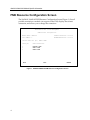
1
SmartSwitch 9000
9A426-01/9A426-02
Local Management Appendix
9031919-02
Appendix
9A426-01/9A426-02
Module Specific Information
Introduction
This appendix contains local management information that is specific to the
following ATM Modules:
•
•
9A426-01 (1 active front panel port; 1 stand-by front panel port)
9A426-02 (2 active front panel ports)
Local Management Screens
The screens shown in this appendix are for the 9A426-02 ATM Module. The
screens for the 9A426-01 ATM Module differ in that there is no Port # field, since
the 9A426-01 ATM Module has only one active front panel port.
1
9A426-01/9A426-02 Module Specific Information
Module Interfaces
The 9A426-01 ATM Module has seven interfaces. Table 1 lists the identifying
number, name, and description of each interface.
Table 1. 9A426-01 ATM Module Interfaces
Interface
Number
Interface
Name
Interface
Description
1
SMB-1
1 Mbps System Management Bus
2
SMB-10
10 Mbps System Management Bus
3
HOST 1
i960 Interface to SmartSwitch Core
4
HOST 2
i960 Interface to SmartSwitch Core
5
INB
Internal Network Bus
6
ATM-1
ATM Front Panel Port 1 (APIM)
7
FNB
Flexible Network Bus
The 9A426-02 ATM Module has eight interfaces. Table 2 lists the identifying
number, name, and description of each interface.
Table 2. 9A426-02 ATM Module Interfaces
Interface
Number
Interface
Name
Interface
Description
1
SMB-1
1 Mbps System Management Bus
2
SMB-10
10 Mbps System Management Bus
3
HOST 1
i960 Interface to SmartSwitch Core
4
HOST 2
i960 Interface to SmartSwitch Core
5
INB
Internal Network Bus
6
ATM-1
ATM Front Panel Port 1 (APIM)
7
ATM-2
ATM Front Panel Port 2 (APIM)
8
FNB
Flexible Network Bus
Use the numbers in Table 1 or Table 2 to configure your module’s default interface
(see the General Configuration Screen).
2
9A426-01/9A426-02 Module Specific Information
Modifying Fields and User Privileges
To modify fields on these modules, you must have read-write or super-user
privileges. If you have read-only privileges, you can view information; however,
you cannot modify any fields.
Virtual Channels and Virtual Paths
Rather than addressing cells to a specific destination, as in a LAN, ATM addresses
cells to Virtual Channels (VCs) and/or Virtual Paths (VPs). This addressing takes
place in the header field of the ATM cell.
VCs and VPs are bi-directional (i.e., they transfer information in both directions
on a single channel or path) and are “set up” between devices on the ATM
network prior to transmission. Similar to WAN transmission, ATM technology
provides the ability of sending several VCs together over a VP, and several VPs
over an ATM link segment.
Permanent and Switched Virtual Channels
ATM networks use two different types of Virtual Channels:
•
•
Permanent Virtual Channels (PVCs)
Switched Virtual Channels (SVCs).
The difference between PVCs and SVCs exists in the channel setup.
PVCs are pre-configured by an administration function, and are usually
established for long-term use. After setting up this channel, nothing else is
required by the network to transfer information between the two established
points. This type of virtual channelling is established through a local or remote
management interface.
SVCs use a signaling and network switching procedure to set up dynamically. In
other words, SVCs are established “on the fly,” as needed for a particular service,
used to transmit on the short term, and then terminated.
3
9A426-01/9A426-02 Module Specific Information
FNB Resource Configuration Screen
The 9A426-01/9A426-02 FNB Resource Configuration Screen (Figure 1), lists all
possible connections a module can support on the FNB, displays the current
connection, and allows you to change the connection.
SmartSwitch 9000
Local Management
FNB Resource Configuration
Module Name: 9A426-02
Slot Number: 5
Current FDDI Con: (#2)
Firmware Revision: 01.00.01
BOOTPROM Revision: 01.01.01
FNB1<->ATM
Config ID
FDDI Connections
1
2
3
NORING<->ATM
FNB1<->ATM
FNB2<->ATM
SAVE
EXIT
RETURN
Figure 1. 9A426-01/9A426-02 FNB Resource Configuration Screen
4
9A426-01/9A426-02 Module Specific Information
FNB Resource Configuration Screen Fields
The following information briefly explains each FNB Resource Configuration
Screen field.
Current FDDI Con:
Displays the current connections of the selected module to the
SmartSwitch 9000 FNB.
Config ID
Displays an identification number that is automatically assigned to each
configuration.
FDDI Connections
Displays all possible connections of the selected module to the
SmartSwitch 9000 FNB.
Changing the Current FNB Connection
To change the current FNB connection:
1. Use the arrow keys to highlight the desired FDDI connection.
2. Press the Return key.
3. The connection you selected appears in the Current FDDI Con: field.
4. Use the arrow keys to highlight SAVE, then press the Return key.
The message “SAVED OK” appears. This message indicates that the FNB
connection you selected has been implemented. If you exit without saving, the
message “NOT SAVED -- PRESS SAVE TO KEEP CHANGES” appears, and
the FNB connection you selected will not be implemented.
5. Use the arrow keys to highlight RETURN, then press the Return key.
5
9A426-01/9A426-02 Module Specific Information
Connection Table Screen
The 9A426-01/9A426-02 Connection Table Screen (Figure 2), displays the
currently configured connections on the module.
SmartSwitch 9000
Local Management
9A426-02 Connection Table
Module Name: 9A426-02
Slot Number: 5
Firmware Revision: 01.00.01
BOOTPROM Revision: 01.01.01
ATM Port Current Connections:
VPI
0
0
ELAN:
PORT #:
1
VCI
0005
0016
2
ELAN:
Encapsulation Type
Other
Other
EXIT
AAL Type
5
5
ADD/DELETE
ENTRY
Figure 2. 9A426-01/9A426-02 Connection Table Screen
6
RETURN
9A426-01/9A426-02 Module Specific Information
Connection Table Screen Fields
The following information briefly explains each Connection Table Screen field.
ATM Port Current Connections
Number of virtual circuits that are currently open for this port.
ELAN:
Name of the ELAN to which this client is joined.
NOTE
For more detailed information about this field, see the description for the ELAN
Name: field on page 13.
VPI
Displays the Virtual Path Identifier number of the listed PVC or SVC.
VCI
Displays the Virtual Channel Identifier number of the listed PVC or SVC.
Encapsulation Type
Displays the method used to encapsulate data at the ATM Adaptation Layer 5
(AAL5) for each connection. The 9A426-01 and 9A426-02 ATM Modules support
the following methods of encapsulation:
•
VC Mux 802.3 LANE (default)
VC Based Multiplexed 802.3 LAN Emulation. This is the encapsulation type
used when the connection is set up via SVCs. These happen automatically in
the network with no user intervention.
•
VC Mux Bridged 802.3
VC Based Multiplexing for bridged protocols. You can choose this
encapsulation type for PVCs to do bridging.
7
9A426-01/9A426-02 Module Specific Information
•
LLC Encapsulation
Logical Link Control for Bridged Protocols. You can choose this encapsulation
type for PVCs. You cannot use this encapsulation type for SVCs.
LLC Encapsulation inserts an LLC SNAP header for each legacy LAN
network type that is being encapsulated onto ATM. LLC Encapsulation is
desirable when it is not feasible for a larger number of VCs to be supported,
due to ATM device capacity limitations or other outside factors.
•
Other
This encapsulation type is for reserved connections that are defaults built into
most (if not all) ATM LANE 1.0 compliant devices. In other words, they are
neither configured by hand nor set up dynamically.
AAL Type
Displays the type of ATM adaptation layer (AAL) used on this VCC. The AAL
divides the user information into segments suitable for packaging into series of
ATM cells. The AAL types are:
•
•
AAL3/4
AAL5 (default)
ELAN: (Modifiable)
Selects the ELAN for which connections are to be displayed.
To select another ELAN, use the arrow keys to highlight the ELAN: field (bottom
left corner of the screen), then press the Space Bar.
PORT #: (Toggle)
Selects a specific ATM port.
To select another port (if applicable), use the arrow keys to highlight the PORT #:
field (bottom left corner of the screen), then press the Space Bar.
Displaying the Add/Delete Entry Screen
To display the Add/Delete Entry Screen, use the arrow keys to highlight
ADD/DELETE ENTRY, then press the Return key.
8
9A426-01/9A426-02 Module Specific Information
Add/Delete Entry Screen
The 9A426-01/9A426-02 Add/Delete Entry Screen (Figure 3), is used to add or
delete a PVC on the module.
SmartSwitch 9000
Local Management
9A426-02 ADD/DELETE ENTRY
Module Name: 9A426-02
Slot Number: 5
Firmware Revision: 01.00.01
BOOTPROM Revision: 01.01.01
ATM Port Current Connections:
VPI
VCI
2
AAL Type
[ ]
ADD
DELETE
ELAN:
Encapsulation Type
[
EXIT
]
RETURN
Figure 3. 9A426-01/9A426-02 Add/Delete Entry Screen
9
9A426-01/9A426-02 Module Specific Information
Add/Delete Entry Screen Fields
The following information briefly explains each Add/Delete Entry Screen field.
VPI
Displays the Virtual Path Identifier number of the connection you want to add or
delete.
VCI
Displays the Virtual Channel Identifier number of the connection you want to add
or delete.
AAL Type (Toggle)
Displays the types of ATM adaptation layer used on this VCC. Use the Space Bar
to select one of the following choices:
•
•
AAL3/4
AAL5 (default)
Encapsulation Type (Toggle)
Displays the methods used to encapsulate data at the ATM Adaptation Layer 5
(AAL5) for each connection. The 9A426-01/9A426-02 modules support the
following methods of encapsulation:
•
VC Mux 802.3 LANE (default)
VC Based Multiplexed 802.3 LAN Emulation. This is the encapsulation type
used when the connection is set up via SVCs. These happen automatically in
the network with no user intervention.
•
VC Mux Bridged 802.3
VC Based Multiplexing for bridged protocols. You can choose this
encapsulation type for PVCs to do bridging.
•
LLC Encapsulation
Logical Link Control for Bridged Protocols. You can choose this encapsulation
type for PVCs. You cannot use this encapsulation type for SVCs.
LLC Encapsulation inserts an LLC SNAP header for each legacy LAN
network type that is being encapsulated onto ATM. LLC Encapsulation is
desirable when it is not feasible for a larger number of VCs to be supported,
due to ATM device capacity limitations or other outside factors.
•
10
Other
This encapsulation type is for reserved connections that are defaults built into
most (if not all) ATM LANE 1.0 compliant devices. In other words, they are
neither configured by hand nor set up dynamically.
9A426-01/9A426-02 Module Specific Information
Adding PVCs to the Connection Table
To add a PVC to the Connection Table:
1. Go to the Add/Delete Entry Screen.
2. Use the arrow keys to move the cursor to the VPI field.
3. Enter the number of the VPI you want to add, then press the Tab key.
4. Enter the number of the VCI you want to add, then press the Tab key.
5. Press the Space Bar to select the AAL type.
6. Press the Tab key.
7. Press the Space Bar to select the Encapsulation Type.
8. Use the arrow keys to highlight ADD, then press the Return key.
The message “ENTRY ADDED” is displayed.
Deleting PVCs From the Connection Table
To delete a PVC from the Connection Table:
1. Go to the Add/Delete Entry Screen.
2. Use the arrow keys to move the cursor to the VPI field.
3. Enter the number of the VPI you want to delete, then press the Tab key.
4. Enter the number of the VCI you want to delete, then press the Tab key.
5. Use the arrow keys to highlight DELETE, then press the Return key.
The message “ENTRY DELETED” is displayed.
11
9A426-01/9A426-02 Module Specific Information
LEC Administration Screen
The 9A426-01/9A426-02 LEC Administration Screen (Figure 4), is used to add,
delete, modify, or view LAN Emulation attributes on the module.
SmartSwitch 9000
Local Management
9A426-02 LEC Administration
Module Name: 9A426-02
Slot Number: 5
Firmware Revision: 01.00.01
BOOTPROM Revision: 01.01.01
Configure LEC: [Automatic]
ELAN Name:
Max MTU Size: [1516]
LAN Type: [802.3]
LES ATM Address: 0000000000000000000000000000000000000000
SAVE
ELAN:
PORT #:
1
MODIFY
CREATE
DELETE
EXIT
Figure 4. 9A426-01/9A426-02 LEC Administration Screen
12
RETURN
9A426-01/9A426-02 Module Specific Information
LEC Administration Screen Fields
The following information briefly explains each LEC Administration Screen field.
Configure LEC (Toggle)
Specifies whether the LAN Emulation Client should auto-configure the next time
it is started. Use the Space Bar to select one of the following choices:
NOTE
•
Automatic (default) - A client uses a LAN Emulation Configuration Server
(LECS) to learn the ATM address of its LAN Emulation Server and to obtain
other parameters.
•
Manually - Management tells the client the ATM address of its LAN Emulation
Server (LES) and the values of other parameters.
If you set Configure LEC to Automatic, do not write to any other attribute on the
LEC Administration screen.
ELAN Name
The name of the ELAN to which this client is joined.
By default, the unit makes a LANE join request to the ATM network with the
ELAN name blank (no entry). By popular LANE convention, Join Requests of this
type will put that client into the first configured ELAN on the LECS (also known
as the “default ELAN”). Assume this ELAN is named “ELAN1”. Once the device
has successfully completed the Join process, all ATM-specific Local Management
screens will then reflect “ELAN: ELAN1”. This means that all Local Management
screen information pertains to the “ELAN1” ELAN.
To set the device back to join the “default” ELAN, you must delete the current
ELAN (ELAN1). After the current ELAN is deleted, a message is displayed that
states that there are no longer any active ELANs. Now, you can move to the
ELAN Name: field. Press the Space Bar, then the Return key. Highlight SAVE and
press the Return key. This will cause the device to join the “default ELAN” again.
Since we support just a single ELAN, you cannot create a new ELAN unless all
current ELANs have been deleted.
NOTE
Future releases will support multiple ELANs. Check your release notes to
determine whether your release supports multiple ELANs.
13
9A426-01/9A426-02 Module Specific Information
If there are currently no active ELANs, then all choices on the ATM Specific
Configuration Screen will result in the message “No ACTIVE ELAN present”. You
can only access the Connection Table screen and the LEC Administration screen.
You cannot access the LEC Properties screen, since there is no information.
Max MTU Size (Toggle)
The maximum data frame size that this client will use the next time it returns to
the Initial State. Use the Space Bar to select one of the following choices:
•
•
1516 (default)
4544
LAN Type (Toggle)
The data frame format this LEC is using currently. Use the Space Bar to select one
of the following choices:
•
•
802.3 (default)
802.5
LES ATM Address
The LES this client will use the next time it is started in manual configuration
mode.
ELAN: (Modifiable)
Selects the ELAN for which attributes are to be displayed.
To select another ELAN, use the arrow keys to highlight the ELAN: field (bottom
left corner of the screen), then press the Space Bar.
PORT #: (Toggle)
Selects a specific ATM port.
To select another port (if applicable), use the arrow keys to highlight the PORT #:
field (bottom left corner of the screen), then press the Space Bar.
Adding an ELAN
NOTE
Remember, while we support just a single ELAN, you cannot create a new ELAN
unless all current ELANs have been deleted.
To add an ELAN:
1. Use the arrow keys to highlight CREATE, then press the Return key.
2. Use the arrow keys to move to the ELAN Name field.
14
9A426-01/9A426-02 Module Specific Information
3. Type the name of the ELAN you want to add.
4. Use the arrow keys to move to the Configure LEC, Max MTU Size, and LAN
Type fields. Select the appropriate choice for each field.
5. Use the arrow keys to highlight SAVE, then press the Return key.
The message “SAVED OK” is displayed.
Deleting an ELAN
To delete an ELAN:
1. Use the arrow keys to highlight DELETE, then press the Return key.
The message “PRESS SAVE TO CONFIRM DELETE” is displayed.
2. Use the arrow keys to highlight SAVE, then press the Return key.
The message “SAVED OK” is displayed. The ELAN Name field will be updated
after you exit the LEC Administration Screen.
Modifying an ELAN
To modify an ELAN:
1. Use the arrow keys to highlight MODIFY, then press the Return key.
2. Use the arrow keys to move to the field you want to modify.
3. Press the Space Bar to modify (select) another option.
4. Use the arrow keys to highlight SAVE, then press the Return key.
The message “SAVED OK” is displayed.
15
9A426-01/9A426-02 Module Specific Information
LEC Properties Screen
The 9A426-01/9A426-02 LEC Properties Screen (Figure 5), displays information
about the various LAN Emulation components.
SmartSwitch 9000
Local Management
9A426-02 LEC PROPERTIES
Module Name: 9A426-02
Slot Number: 5
Firmware Revision: 01.00.01
BOOTPROM Revision: 01.01.01
LECS ATM Address: 0000000000000000000000000000000000000000
Configuration Direct VPI/VCI: 0,
0
LEC
ATM Address: 0000000000000000000000000000000000000000
ID:
0
State: Initial State
LES
ATM Address: 0000000000000000000000000000000000000000
Control Direct
VPI/VCI: 0,
0
Control Distribute
VPI/VCI: 0,
0
BUS
ATM Address: 0000000000000000000000000000000000000000
Multicast Send
VPI/VCI: 0,
0
Multicast Forward
VPI/VCI: 0,
0
PORT #:
1
ELAN:
EXIT
Figure 5. 9A426-01/9A426-02 LEC Properties Screen
16
RETURN
9A426-01/9A426-02 Module Specific Information
LEC Properties Screen Fields
The following information briefly explains each LEC Properties Screen field.
LECS ATM Address
Displays the ATM address of the LECS (if it is known), or the empty string.
LECS Configuration Direct VPI/VCI
A bi-directional, point to point connection set up by the LEC to get configuration
information and the ATM address of the LES.
LEC ATM Address
Displays the ATM address of this LEC entry.
LEC ID
Displays the two-byte ID assigned to this LEC by the LES.
LES ATM Address
Displays the LES address for the ELAN of which this client is a member.
LES Control Direct VPI/VCI
A bi-directional, point to point VPI/VCI used by the LEC to issue LE_ARP
requests and can be used by the LES to forward LE_ARP replies. This connection
is maintained for the duration of the LECs participation in the ELAN.
LES Control Distribute VPI/VCI
An optional point to multi-point, or point to point connection. The LES uses this
to forward LE_ARP requests that it cannot process. This connection is maintained
for the duration of the LECs participation in the ELAN.
BUS ATM Address
Displays the ATM address of the Broadcast and Unknown Server or LAN
Emulation Client whose MAC address is stored in ‘leArpMacAddress’.
BUS Multicast Send VPI/VCI
A bi-directional, point to point VPI/VCI used by the LEC to send broadcast,
multicast and unknown unicast traffic to the BUS. This connection is maintained
for the duration of the LECs participation in the ELAN.
BUS Multicast Forward VPI/VCI
A point to multi-point or a unidirectional point to point VPI/VCI from the BUS to
each LEC. It is used by the BUS to forward traffic received from the LECS.
17
9A426-01/9A426-02 Module Specific Information
SVC Signalling Screen
The 9A426-01/9A426-02 SVC Signalling Screen (Figure 6), is used to change the
type of SVC signalling and LAN Emulation used by the module.
SmartSwitch 9000
Local Management
9A426-02 SVC Signalling
Module Name: 9A426-02
Slot Number: 5
Firmware Revision: 01.00.01
BOOTPROM Revision: 01.01.01
Signalling/LAN Emulation Type: [UNI3.0/LANE1.0]
ILMI: [ON]
LEC ATM Address: 0000000000000000000000000000000000000000
SAVE
PORT #:
1
Figure 6. 9A426-01/9A426-02 SVC Signalling Screen
18
EXIT
RETURN
9A426-01/9A426-02 Module Specific Information
SVC Signalling Screen Fields
The following information briefly explains each SVC Signalling Screen field.
Signalling/LAN Emulation Type (Toggle)
Displays the types of signalling and LAN Emulation to be used by the module.
Use the Space Bar to select one of the following choices:
•
•
UNI3.1/LANE1.0
UNI3.0/LANE1.0
ILMI (Toggle)
Enables or disables the Interim Local Management Interface (ILMI) used in UNI
signalling. If you disable ILMI, you must enter the LEC ATM Address. Use the
Space Bar to select one of the following:
•
•
!
ILMI ON (default)
ILMI OFF
After you toggle this field, the module reboots automatically.
CAUTION
LEC ATM Address (Modifiable, if ILMI is OFF)
Displays the ATM address of this LEC.
NOTE
If you disable ILMI (ILMI is OFF), you must manually enter the address of the
LEC in this field.
PORT #: (Toggle)
Selects a specific ATM port.
To select another port (if applicable), use the arrow keys to highlight the PORT #:
field (bottom left corner of the screen), then press the Space Bar.
19
9A426-01/9A426-02 Module Specific Information
Diagnostics Screen
The 9A426-01/9A426-02 Diagnostics Screen (Figure 7), is used to enable or disable
extended diagnostics for the module.
SmartSwitch 9000
Local Management
9A426-02 Diagnostics
Module Name: 9A426-02
Slot Number: 5
Firmware Revision: 01.00.01
BOOTPROM Revision: 01.01.01
Extended Diagnostics: [ENABLED ]
SAVE
EXIT
Figure 7. 9A426-01/9A426-02 Diagnostics Screen
20
RETURN
9A426-01/9A426-02 Module Specific Information
Diagnostics Screen Field
The following information briefly explains the Diagnostics Screen field.
Extended Diagnostics (Toggle)
Enables or disables Extended Diagnostics for the ATM module. Use the Space Bar
to select one of the following choices:
•
NOTE
ENABLED - At start up, Extended Diagnostics test exhaustively all hardware
involved with the ATM interfaces.
Enabling Extended Diagnostics increases the module’s start-up time by 6 to 7
minutes.
•
DISABLED - At start up, no Extended Diagnostics testing is performed.
Enabling and Disabling Extended Diagnostics
Use the following procedure to enable or disable Extended Diagnostics (from the
9A426-01/9A426-02 Diagnostics Screen):
1. Use the arrow keys to highlight the Extended Diagnostics: field.
2. Press the Space Bar to display ENABLED or DISABLED.
3. Use the arrow keys to highlight SAVE, then press the Return key.
The enabling/disabling of extended diagnostics will occur the next time the
module reboots.
21
9A426-01/9A426-02 Module Specific Information
22