1
SmartSwitch Router
User Reference Manual
9032578-02
Notice
2
SSR User Reference Manual
Notice
Notice
Cabletron Systems reserves the right to make changes in specifications and other information contained in this
document without prior notice. The reader should in all cases consult Cabletron Systems to determine whether
any such changes have been made.
The hardware, firmware, or software described in this manual is subject to change without notice.
IN NO EVENT SHALL CABLETRON SYSTEMS BE LIABLE FOR ANY INCIDENTAL, INDIRECT,
SPECIAL, OR CONSEQUENTIAL DAMAGES WHATSOEVER (INCLUDING BUT NOT LIMITED TO
LOST PROFITS) ARISING OUT OF OR RELATED TO THIS MANUAL OR THE INFORMATION
CONTAINED IN IT, EVEN IF CABLETRON SYSTEMS HAS BEEN ADVISED OF, KNOWN, OR SHOULD
HAVE KNOWN, THE POSSIBILITY OF SUCH DAMAGES.
© Copyright November 1998 by:
Cabletron Systems, Inc.
35 Industrial Way
Rochester, NH 03867-5005
All Rights Reserved
Printed in the United States of America
Order Number: 9032578-02
LANVIEW is a registered trademark, and SmartSwitch is a trademark of
Cabletron Systems, Inc.
CompuServe is a registered trademark of CompuServe, Inc.
i960 microprocessor is a registered trademark of Intel Corp.
Ethernet is a trademark of Xerox Corporation.
FCC Notice
This device complies with Part 15 of the FCC rules. Operation is subject to the following two conditions: (1) this
device may not cause harmful interference, and (2) this device must accept any interference received, including
interference that may cause undesired operation.
NOTE: This equipment has been tested and found to comply with the limits for a Class A digital device,
pursuant to Part 15 of the FCC rules. These limits are designed to provide reasonable protection against harmful
interference when the equipment is operated in a commercial environment. This equipment uses, generates, and
can radiate radio frequency energy and if not installed in accordance with the operator’s manual, may cause
harmful interference to radio communications. Operation of this equipment in a residential area is likely to cause
interference in which case the user will be required to correct the interference at his own expense.
WARNING: Changes or modifications made to this device which are not expressly approved by the party
responsible for compliance could void the user’s authority to operate the equipment.
SSR User Reference Manual
3
Notice
VCCI Notice
This is a Class A product based on the standard of the Voluntary Control Council for Interference by Information
Technology Equipment (VCCI). If this equipment is used in a domestic environment, radio disturbance may
arise. When such trouble occurs, the user may be required to take corrective actions.
DOC Notice
This digital apparatus does not exceed the Class A limits for radio noise emissions from digital apparatus set out
in the Radio Interference Regulations of the Canadian Department of Communications.
Le présent appareil numérique n’émet pas de bruits radioélectriques dépassant les limites applicables aux
appareils numériques de la class A prescrites dans le Règlement sur le brouillage radioélectrique édicté par le
ministère des Communications du Canada.
4
SSR User Reference Manual
Notice
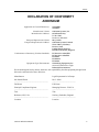
DECLARATION OF CONFORMITY
ADDENDUM
Application of Council Directive(s):
Manufacturer’s Name:
Manufacturer’s Address:
European Representative Name:
European Representative Address:
Conformance to Directive(s)/Product Standards:
Equipment Type/Environment:
89/336/EEC
73/23/EEC
Cabletron Systems, Inc.
35 Industrial Way
PO Box 5005
Rochester, NH 03867
Mr. J. Solari
Cabletron Systems Limited
Nexus House, Newbury
Business Park
London Road, Newbury
Berkshire RG13 2PZ, England
EC Directive 89/336/EEC
EC Directive 73/23/EEC
EN 55022
EN 50082-1
EN 60950
Networking Equipment, for
use in a Commercial or Light
Industrial Environment.
We the undersigned, hereby declare, under our sole responsibility, that the equipment packaged with
this notice conforms to the above directives.
Manufacturer
Legal Representative in Europe
Mr.
Ronald Fotino
____________________________________________________
Mr.
J. Solari
____________________________________
Full Name
Full Name
Principal Compliance Engineer
____________________________________________________
Managing Director - E.M.E.A.
____________________________________
Title
Title
Rochester,
NH, USA
____________________________________________________
Newbury, Berkshire, England
____________________________________
Location
Location
SSR User Reference Manual
5
Notice
6
SSR User Reference Manual
Contents
Preface ..................................................................................................... 15
About This Manual .............................................................................................................. ..15
Who Should Read This Manual? .........................................................................................15
How to Use This Manual ......................................................................................................16
Related Documentation.........................................................................................................16
Chapter 1: SmartSwitch Router Product Overview.............................. 17
Supported Media (Encapsulation Type).............................................................................19
Supported Routing Protocols ...............................................................................................19
Configuring the Cabletron SmartSwitch Router ...............................................................20
Understanding the Command Line Interface.............................................................20
Basic Line Editing Commands ......................................................................................20
Access Modes ..................................................................................................................21
User Mode........................................................................................................................22
Enable Mode ....................................................................................................................22
Configure Mode ..............................................................................................................24
Boot PROM Mode ...........................................................................................................25
Disabling a Function or Feature....................................................................................25
Loading System Images and Configuration Files .............................................................25
Boot and System Image..................................................................................................26
Configuration Files .........................................................................................................26
Loading System Image Software ..................................................................................26
Loading Boot PROM Software......................................................................................27
Activate the Configuration Commands in the Scratchpad.......................................28
Copy the Configuration to the Startup Configuration File.......................................29
Managing the SSR ..................................................................................................................29
Set SSR Name ..................................................................................................................30
Set SSR Date and Time ...................................................................................................30
Configure NTP ................................................................................................................30
Configure the SSR CLI ...................................................................................................30
Configure SNMP Services .............................................................................................31
Configure DNS ................................................................................................................31
Monitoring Configuration ....................................................................................................31
Chapter 2: Bridging Configuration Guide ............................................. 33
Bridging Overview.................................................................................................................33
Spanning Tree (IEEE 802.1d) .........................................................................................33
Bridging Modes (Flow-Based and Address-Based) ...................................................34
VLAN Overview ....................................................................................................................34
SmartSwitch Router User Reference Manual
7
Contents
Port-based VLANs .................................................................................................. 35
MAC-address-based VLANs................................................................................. 35
Protocol-based VLANs........................................................................................... 35
Subnet-based VLANs ............................................................................................. 35
Multicast-based VLANs......................................................................................... 36
Policy-based VLANs .............................................................................................. 36
SSR VLAN Support........................................................................................................ 36
VLANs and the SSR................................................................................................ 36
Ports, VLANs, and L3 Interfaces .......................................................................... 37
Access Ports and Trunk Ports (802.1Q support)................................................. 37
Explicit and Implicit VLANs................................................................................. 38
Configuring SSR Bridging Functions ................................................................................. 38
Configure Address-based or Flow-based Bridging .................................................. 38
Configuring Spanning Tree .......................................................................................... 39
Adjust Spanning-Tree Parameters............................................................................... 40
Set the Bridge Priority ............................................................................................ 40
Set a Port Priority .................................................................................................... 40
Assign Port Costs .................................................................................................... 41
Adjust Bridge Protocol Data Unit (BPDU) Intervals ......................................... 41
Adjust the Interval between Hello Times .................................................... 41
Define the Forward Delay Interval ............................................................... 41
Define the Maximum Age .............................................................................. 42
Configuring a Port or Protocol based VLAN............................................................. 42
Create a Port or Protocol Based VLAN................................................................ 42
Adding Ports to a VLAN ....................................................................................... 42
Configuring VLAN Trunk Ports .................................................................................. 42
Configure Bridging for Non-IP/IPX Protocols.......................................................... 43
Configure Layer-2 Filters .............................................................................................. 43
Monitor Bridging............................................................................................................... .... 43
Configuration Examples....................................................................................................... 44
Creating an IP or IPX VLAN ........................................................................................ 44
Chapter 3: IP Routing Configuration Guide .......................................... 45
IP Routing Overview ............................................................................................................ 45
IP Routing Protocols ...................................................................................................... 46
Unicast Routing Protocols ..................................................................................... 46
Multicast Routing Protocols .................................................................................. 46
Configuring IP Interfaces and Parameters ........................................................................ 47
Configure IP Addresses to Ports.................................................................................. 47
Configure IP Interfaces for a VLAN............................................................................ 47
Specify Ethernet Encapsulation Method .................................................................... 47
Configure Address Resolution Protocol ..................................................................... 48
Configure ARP Cache Entries ............................................................................... 48
Configure Proxy ARP............................................................................................. 48
Configure DNS Parameters .......................................................................................... 49
Configure IP Services (ICMP) ...................................................................................... 49
Configure IP Helper....................................................................................................... 49
Configure Direct Broadcast .......................................................................................... 50
Monitor IP Parameters.......................................................................................................... 50
Configuration Examples....................................................................................................... 51
8
SmartSwitch Router User Reference Manual
Contents
Assigning IP/IPX Interfaces..........................................................................................51
Chapter 4: RIP Configuration Guide ...................................................... 53
RIP Overview..........................................................................................................................53
Configure RIP .........................................................................................................................53
Enabling and Disabling RIP ..........................................................................................54
Configuring RIP Interfaces ............................................................................................54
Configure RIP Parameters .............................................................................................54
Configure RIP Route Preference ...................................................................................55
Configure RIP Route Default-Metric ...........................................................................56
Monitoring RIP .......................................................................................................................56
Configuration Example .........................................................................................................57
Chapter 5: OSPF Configuration Guide................................................... 59
OSPF Overview .................................................................................................................. ....59
OSPF Multipath...............................................................................................................60
Configure OSPF................................................................................................................. .....60
Enable OSPF.................................................................................................................... .60
Configure OSPF Interface Parameters .........................................................................61
Configure an OSPF Area................................................................................................62
Configure OSPF Area Parameters ................................................................................63
Create Virtual Links........................................................................................................63
Configure Autonomous System External (ASE) Link Advertisements ..................64
Configure OSPF over Non-Broadcast Multiple Access.............................................64
Monitoring OSPF....................................................................................................................65
OSPF Configuration Examples.............................................................................................66
Exporting All Interface & Static Routes to OSPF .........................................67
Export All RIP, Interface & Static Routes to OSPF ......................................67
Chapter 6: BGP Configuration Guide..................................................... 71
BGP Overview ........................................................................................................................71
The SSR BGP Implementation.......................................................................................72
Basic BGP Tasks......................................................................................................................72
Setting the Autonomous System Number ..................................................................73
Setting the Router ID ......................................................................................................73
Configuring a BGP Peer Group ....................................................................................73
Adding a BGP Peer .........................................................................................................75
Starting BGP.....................................................................................................................75
Using AS-Path Regular Expressions ............................................................................75
AS-Path Regular Expression Examples ................................................................76
Using the AS Path Prepend Feature.............................................................................77
Notes on Using the AS Path Prepend Feature.....................................................78
BGP Configuration Examples ..............................................................................................78
BGP Peering Session Example ......................................................................................78
IBGP Configuration Example........................................................................................81
IBGP Routing Group Example...............................................................................81
IBGP Internal Group Example...............................................................................84
EBGP Multihop Configuration Example.....................................................................87
Community Attribute Example ....................................................................................90
SmartSwitch Router User Reference Manual
9
Contents
Notes on Using Communities ............................................................................... 97
Local_Pref Attribute Example ...................................................................................... 97
Notes on Using the Local_Pref Attribute ............................................................ 99
Multi-Exit Discriminator Attribute Example ............................................................. 99
EBGP Aggregation Example....................................................................................... 101
Route Reflection Example........................................................................................... 102
Notes on Using Route Reflection........................................................................ 105
Chapter 7: Routing Policy Configuration Guide.................................. 107
Route Import and Export Policy Overview..................................................................... 107
Preference ...................................................................................................................... 108
Import Policies.............................................................................................................. 109
Import-Source........................................................................................................ 109
Route-Filter ............................................................................................................ 110
Export Policies .............................................................................................................. 110
Export-Destination................................................................................................ 110
Export-Source ........................................................................................................ 110
Route-Filter ............................................................................................................ 111
Specifying a Route Filter ............................................................................................. 111
Aggregates and Generates .......................................................................................... 112
Aggregate-Destination ......................................................................................... 113
Aggregate-Source.................................................................................................. 113
Route-Filter ............................................................................................................ 114
Authentication .............................................................................................................. 114
Authentication Methods ...................................................................................... 114
Authentication Keys and Key Management ..................................................... 115
Configure Simple Routing Policies................................................................................... 115
Redistributing Static Routes ....................................................................................... 116
Redistributing Directly Attached Networks ............................................................ 116
Redistributing RIP into RIP ........................................................................................ 117
Redistributing RIP into OSPF..................................................................................... 117
Redistributing OSPF to RIP ........................................................................................ 117
Redistributing Aggregate Routes .............................................................................. 117
Simple Route Redistribution Examples .................................................................... 118
Example 1: Redistribution into RIP .................................................................... 118
Exporting a Given Static Route to All RIP Interfaces ............................... 119
Exporting All Static Routes to All RIP Interfaces...................................... 119
Exporting All Static Routes Except the Default Route to All RIP
Interfaces ..................................................................................................... 119
Example 2: Redistribution into OSPF................................................................. 119
Exporting All Interface & Static Routes to OSPF ...................................... 120
Export all RIP, Interface & Static Routes to OSPF..................................... 120
Configure Advanced Routing Policies............................................................................. 121
Export Policies .............................................................................................................. 121
Creating an Export Destination.................................................................................. 123
Creating an Export Source .......................................................................................... 123
Import Policies.............................................................................................................. 123
Creating an Import Source.......................................................................................... 124
Creating a Route Filter ................................................................................................ 124
Creating an Aggregate Route ..................................................................................... 124
10
SmartSwitch Router User Reference Manual
Contents
Creating an Aggregate Destination............................................................................126
Creating an Aggregate Source ....................................................................................126
Examples of Import Policies........................................................................................126
Example 1: Importing from RIP...........................................................................126
Importing a Selected Subset of Routes from One RIP Trusted
Gateway........................................................................................................128
Importing a Selected Subset of Routes from All RIP Peers Accessible Over
a Certain Interface.......................................................................................129
Example 2: Importing from OSPF .......................................................................129
Importing a Selected Subset of OSPF-ASE Routes ....................................132
Examples of Export Policies ........................................................................................133
Example 1: Exporting to RIP ................................................................................133
Exporting a Given Static Route to All RIP Interfaces ................................134
Exporting a Given Static Route to a Specific RIP Interface ......................135
Exporting All Static Routes Reachable Over a Given Interface to a Specific
RIP-Interface ................................................................................................136
Exporting Aggregate-Routes into RIP .........................................................136
Example 2: Exporting to OSPF.............................................................................138
Exporting All Interface & Static Routes to OSPF .......................................139
Exporting All RIP, Interface & Static Routes to OSPF...............................140
Chapter 8: Multicast Routing Configuration Guide ........................... 143
IP Multicast Overview.........................................................................................................143
IGMP Overview ............................................................................................................143
DVMRP Overview ........................................................................................................144
Configure IGMP ...................................................................................................................145
Configuring IGMP on an IP Interface ........................................................................145
Configure IGMP Query Interval.................................................................................145
Configure IGMP Response Wait Time.......................................................................145
Configure Per-Interface Control of IGMP Membership..........................................146
Configure DVMRP...............................................................................................................146
Starting and Stopping DVMRP...................................................................................146
Configure DVMRP on an Interface ............................................................................147
Configure DVMRP Parameters...................................................................................147
Configure the DVMRP Routing Metric .....................................................................147
Configure DVMRP TTL & Scope................................................................................148
Configure a DVMRP Tunnel .......................................................................................148
Monitor IGMP & DVMRP...................................................................................................149
Configuration Examples .....................................................................................................150
Chapter 9: IPX Routing Configuration Guide...................................... 151
IPX Routing Overview ........................................................................................................151
RIP (Routing Information Protocol) ...........................................................................151
SAP (Service Advertising Protocol) ...........................................................................152
Configuring IPX RIP & SAP ...............................................................................................153
IPX RIP............................................................................................................................153
IPX SAP ..........................................................................................................................153
Creating IPX Interfaces ................................................................................................153
SmartSwitch Router User Reference Manual
11
Contents
IPX Addresses............................................................................................................... 153
Configuring IPX Interfaces and Parameters.................................................................... 154
Configure IPX Addresses to Ports ............................................................................. 154
Configure IPX Interfaces for a VLAN ....................................................................... 154
Specify IPX Encapsulation Method ........................................................................... 154
Configure IPX Routing ....................................................................................................... 155
Enable IPX RIP.............................................................................................................. 155
Enable SAP .................................................................................................................... 155
Configure Static Routes............................................................................................... 155
Configure Static SAP Table Entries ........................................................................... 156
Control Access to IPX Networks................................................................................ 156
Create an IPX Access Control List ...................................................................... 156
Create an IPX Type 20 Access Control List ....................................................... 157
Create an IPX SAP Access Control List ............................................................. 157
Create an IPX GNS Access Control List............................................................. 157
Create an IPX RIP Access Control List............................................................... 158
Monitor an IPX Network.................................................................................................... 158
Configuration Examples..................................................................................................... 158
Chapter 10: Security Configuration Guide .......................................... 161
Security Overview............................................................................................................... 161
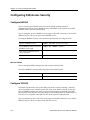
Configuring SSR Access Security...................................................................................... 162
Configure RADIUS ...................................................................................................... 162
Monitor RADIUS .................................................................................................. 162
Configure TACACS ..................................................................................................... 162
Monitor TACACS ................................................................................................. 163
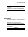
Configure TACACS Plus............................................................................................. 163
Monitor TACACS Plus......................................................................................... 163
Configure Passwords................................................................................................... 164
Layer-2 Security Filters....................................................................................................... 164
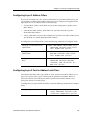
Configuring Layer-2 Address Filters ........................................................................ 165
Configuring Layer-2 Port-to-Address Lock Filters ................................................. 165
Configuring Layer-2 Static Entry Filters................................................................... 166
Configuring Layer-2 Secure Port Filters ................................................................... 166
Monitor Layer-2 Security Filters ................................................................................ 167
Layer-2 Filter Examples............................................................................................... 168
Example 1: Address Filters .................................................................................. 168
Static Entries Example................................................................................... 168
Port-to-Address Lock Examples .................................................................. 169
Example 2 : Secure Ports ...................................................................................... 169
Layer-3 Access Control Lists (ACLs)................................................................................ 170
Layer-3 & Layer-4 Traffic Filters (Access Control List) .......................................... 170
Anatomy of an ACL Rule............................................................................................ 170
Ordering of ACL Rules................................................................................................ 171
Implicit Deny Rule ....................................................................................................... 172
Applying ACLs to Interfaces...................................................................................... 173
Applying ACLs to Services......................................................................................... 174
ACL Logging ................................................................................................................ 174
Maintaining ACLs Offline Using TFTP or RCP....................................................... 175
Maintaining ACLs Using the ACL Editor ................................................................ 176
12
SmartSwitch Router User Reference Manual
Contents
Configure ACL ..............................................................................................................176
Defining an IP ACL ...............................................................................................176
Defining an IPX ACL.............................................................................................177
Applying an ACL to an Interface ........................................................................177
Applying an ACL to a Service .............................................................................177
Edit an ACL with the ACL Editor .......................................................................177
Monitoring Access Control Lists ................................................................................177
Chapter 11: QoS Configuration Guide ................................................ 179
QoS & Layer-2/Layer-3/Layer-4 Flow Overview ..........................................................179
Layer-2, Layer-3 & Layer-4 Flow Specification ........................................................179
Precedence for Layer-3 Flows .....................................................................................180
SSR Queuing Policies....................................................................................................180
Configure Layer-2 QoS........................................................................................................181
Configuring Layer-3 & Layer-4 QoS .................................................................................181
Configuring IP QoS Policies ........................................................................................182
Setting an IP QoS Policy .......................................................................................182
Specifying Precedence for an IP QoS Policy ......................................................182
Configuring IPX QoS Policies .....................................................................................182
Setting an IPX QoS Policy.....................................................................................183
Specifying Precedence for an IPX QoS Policy ...................................................183
Configuring SSR Queueing Policy.....................................................................................183
Allocating Bandwidth for a Weighted-Fair Queuing Policy ..................................183
Monitoring QoS ....................................................................................................................184
Chapter 12: Performance Monitoring Guide ...................................... 185
Performance Monitoring Overview ..................................................................................185
Configuring the SSR for Port Mirroring ....................................................................187
Chapter 13: Hot Swapping
Line Cards and Control Modules....................................................... 189
Hot Swapping Overview ....................................................................................................189
Hot Swapping Line Cards ..................................................................................................189
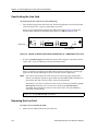
Deactivating the Line Card..........................................................................................190
Removing the Line Card ..............................................................................................190
Installing a New Line Card ..................................................................................191
Hot Swapping One Type of Line Card With Another.............................................191
Hot Swapping a Secondary Control Module ...................................................................191
Deactivating the Control Module ...............................................................................192
Removing the Control Module ...................................................................................192
Installing the Control Module.....................................................................................193
Hot Swapping a Switching Fabric Module (SSR 8600 only)..........................................193
Chapter 14: VRRP Configuration Guide............................................... 195
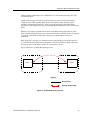
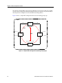
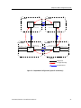
VRRP Overview ...................................................................................................................195
Configuring VRRP ...............................................................................................................195
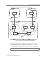
Basic VRRP Configuration...........................................................................................196
Configuration of Router R1 ..................................................................................196
SmartSwitch Router User Reference Manual
13
Contents
Configuration for Router R2................................................................................ 197
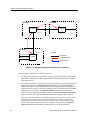
Symmetrical Configuration ........................................................................................ 197
Configuration of Router R1 ................................................................................. 198
Configuration of Router R2 ................................................................................. 199
Multi-Backup Configuration ...................................................................................... 199
Configuration of Router R1 ................................................................................. 201
Configuration of Router R2 ................................................................................. 202
Configuration of Router R3 ................................................................................. 203
Additional Configuration ........................................................................................... 203
Setting the Backup Priority.................................................................................. 204
Setting the Advertisement Interval .................................................................... 204
Setting Pre-empt Mode ........................................................................................ 204
Setting an Authentication Key ............................................................................ 205
Monitoring VRRP ................................................................................................................ 205
ip-redundancy trace..................................................................................................... 205
ip-redundancy show.................................................................................................... 206
VRRP Configuration Notes................................................................................................ 206
14
SmartSwitch Router User Reference Manual
Preface
About This Manual
This manual provides detailed information and procedures for configuring the
SmartSwitch Router SSR software. If you have not yet installed the SSR, use the
instructions in the SmartSwitch Router Getting Started Guide to install the chassis and
perform basic setup tasks, then return to this manual for more detailed configuration
information.
Who Should Read This Manual?
Read this manual if you are a network administrator responsible for configuring and
monitoring the SSR.
SmartSwitch Router User Reference Manual
15
Preface
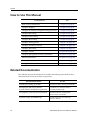
How to Use This Manual
If You Want To
See
Read overview information
Chapter 1 on page 17
Configure bridging
Chapter 2 on page 33
Configure IP interfaces and global routing parameters
Chapter 3 on page 45
Configure RIP routing
Chapter 4 on page 53
Configure OSPF routing
Chapter 5 on page 59
Configure BGP routing
Chapter 6 on page 71
Configure routing policies
Chapter 7 on page 107
Configure IP multicast routing
Chapter 8 on page 143
Configure IPX routing
Chapter 9 on page 151
Configure security
Chapter 10 on page 161
Configure QoS (Quality of Service) parameters
Chapter 11 on page 179
Monitor performance
Chapter 12 on page 185
Hot swap line cards and Control Modules
Chapter 13 on page 189
Configure VRRP
Chapter 14 on page 195
Related Documentation
The Cabletron Systems documentation set includes the following items. Refer to these
other documents to learn more about your product.
For Information About
16
See the
Installing and setting up the SSR
SmartSwitch Router Getting Started Guide
Managing the SSR using Cabletron
Systems’ element management application
CoreWatch User’s Manual and the
CoreWatch online help
The complete syntax for all CLI commands
SmartSwitch Router Command Line
Interface Reference Manual
System messages and SNMP traps
SmartSwitch Router Error Message
Reference Manual
SmartSwitch Router User Reference Manual
Chapter 1
SmartSwitch
Router Product
Overview
The SmartSwitch Router (SSR) provides non-blocking, wire-speed Layer-2 (switching),
Layer-3 (routing) and Layer-4 (application) switching. The hardware provides wire-speed
performance regardless of the performance monitoring, filtering, and Quality of Service
(QoS) features enabled by the software. You do not need to accept performance
compromises to run QoS or access control lists (ACLs).
SmartSwitch Router User Reference Manual
17
Chapter 1: SmartSwitch Router Product Overview
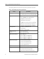
The following table lists the basic hardware and software specifications for the SSR:
Table 1. SSR Hardware and software specifications
Feature
Throughput
•
16-Gbps non-blocking switching fabric
•
15 million packets-per-second routing throughput
•
Up to 250,000 routes
•
Up to 2,000,000 Layer-4 application flows
•
400,000 Layer-2 MAC addresses
•
4,096 Virtual LANs (VLANs)
•
20,000 Layer-2 security and access-control filters
•
3MB input/output buffering per Gigabit port
•
1MB input/output buffering per 10/100 port
•
IP: RIPv1/v2, OSPF, BGP 2,3,4
•
IPX: RIP, SAP
•
Multicast: IGMP, DVMRP
Bridging and VLAN
protocols
•
802.1d Spanning Tree
•
802.1Q (VLAN trunking)
Media Interface protocols
•
802.3 (10Base-T)
•
802.3u (100Base-TX, 100BASE-FX)
•
802.3x (1000Base-SX, 1000Base-LX)
•
802.3z (1000Base-SX, 1000Base-LX)
•
Layer-2 prioritization (802.1p)
•
Layer-3 source-destination flows
•
Layer-4 source-destination flows
•
Layer-4 application flows
RMON
•
RMONv1/v2 for each port
Management
•
SNMP
•
CoreWatch Element Manager (GUI)
•
Emacs-like Command Line Interface (CLI)
Capacity
Routing protocols
Quality of Service (QoS)
18
Specification
SmartSwitch Router User Reference Manual
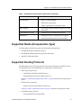
Chapter 1: SmartSwitch Router Product Overview
Table 1. SSR Hardware and software specifications (continued)
Feature
Port mirroring
Specification
•
Traffic to Control Module
•
Traffic from specific ports
•
Traffic to specific chassis slots (line cards)
Hot swapping
•
Power supply (when redundant supply is installed
and online)
Load balancing/sharing
•
Cabletron Systems SMARTtrunk support
Redundancy
•
Redundant and hot-swappable power supplies
•
Virtual Router Redundancy Protocol (VRRP)
Supported Media (Encapsulation Type)
The SSR supports the following industry-standard networking media:
•
IP: IEEE 802.3 SNAP and Ethernet Type II
•
IPX: IEEE 802.3 SNAP, Ethernet Type II, IPX 802.3, 802.2
•
802.1Q VLAN Encapsulation
Supported Routing Protocols
The SSR supports many routing protocols based on open standards. The SSR can receive
and forward packets concurrently from any combination of the following:
•
Interior gateway protocols:
–
Open Shortest Path First (OSPF) Version 2
–
Routing Information Protocol (RIP) Version 1, 2
Chapter 3: “IP Routing Configuration Guide” on page 45 describes these protocols in
detail.
•
Exterior gateway protocol:
–
Border Gateway Protocol (BGP) Version 2,3,4
Chapter 6: “BGP Configuration Guide” on page 71 describes this protocol in detail.
•
Novell IPX routing protocols:
–
Routing Information Protocol (RIP)
SmartSwitch Router User Reference Manual
19
Chapter 1: SmartSwitch Router Product Overview
–
Service Advertising Protocol (SAP)
Chapter 9: “IPX Routing Configuration Guide” on page 151 describes these protocols
in detail.
Configuring the Cabletron SmartSwitch Router
The SSR provides a command line interface (CLI) that allows you to configure and
manage the SSR. The CLI has several command modes, each of which provides a group of
related commands that you can use to configure the SSR and display its status. Some
commands are available to all users; others can be executed only after the user enters an
“Enable” password.
You use the CLI to configure ports, IP/IPX interfaces, routing, switching, security filters
and Quality of Service (QoS) policies.
Understanding the Command Line Interface
The SSR Command Line Interface (CLI) provides access to several different command
modes. Each command mode provides a group of related commands. This chapter
describes how to access and list the commands available in each command mode and
explains the primary uses for each command mode. This chapter also describes the other
features of the user interface.
SSR commands can be entered at a terminal connected to the access server or router using
the command line interface (CLI). The SSR can also be configured using the CoreWatch
Java-based management application. Using CoreWatch is described in the CoreWatch
User’s Guide.
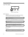
Basic Line Editing Commands
The CLI supports EMACs-like line editing commands. The following table lists some
commonly used commands.
Table 2. Common CLI key commands
Key Sequence
20
Command
Ctrl+A
Move cursor to beginning of line
Ctrl+B
Move cursor back one character
Ctrl+D
Delete character
Ctrl+E
Move cursor to end of line
SmartSwitch Router User Reference Manual
Chapter 1: SmartSwitch Router Product Overview
Table 2. Common CLI key commands (continued)
Key Sequence
Command
Ctrl+F
Move cursor forward one character
Ctrl+N
Scroll to next command in command history (use the cli show
history command to display the history)
Ctrl+P
Scroll to previous command in command history
Ctrl+U
Erase entire line
Ctrl+X
Erase from cursor to end of line
Ctrl+Z
Exit current access mode to previous access mode
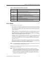
Access Modes
The SSR CLI has four access modes.
•
User – Allows you to display basic information and use basic utilities such as ping but
does not allow you to display SNMP, filter and access control list information or make
other configuration changes. You are in User mode when the command prompt ends
with the > character:
•
Enable – Allows you to display SNMP, filter, and access control information as well as
all the information you can display in User mode. To enter Enable mode, enter the
enable command, then supply the password when prompted. When you are in Enable
mode, the command prompt ends with the # character:
•
Configure – Allows you to make configuration changes. To enter Configure mode, first
enter Enable mode (enable command), then enter the configure command from the
Enable command prompt. When you are in Configure mode, the command prompt
ends with(config).
•
Boot – This mode appears when the SSR the external flash card or the system image is
not found during bootup. You should enter the reboot command to reset the SSR. If the
SSR still fails to bootup, please call Cabletron Technical Support.
Note:
The command prompt will show the name of the SmartSwitch Router in front of
the mode character(s). The default name is “ssr”.
When you are in Configure or Enable mode, enter the exit command or press Ctrl+Z to
exit to the previous access mode.
Note:
When you exit Configure mode, the CLI will ask you whether you want to
activate the configuration commands you have issued. If you enter Y (Yes), the
configuration commands you issued are placed into effect and the SmartSwitch
Router’s configuration is changed accordingly. However, the changes are not
written to the Startup configuration file in the Control Module’s boot flash and
therefore are not reinstated after a reboot.
SmartSwitch Router User Reference Manual
21
Chapter 1: SmartSwitch Router Product Overview
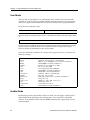
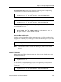
User Mode
After you log in to the SSR, you are automatically in User mode. The User commands
available are a subset of those available in Enable mode. In general, the User commands
allow you to display basic information and use basic utilities such as ping information.
To list the User commands, enter:
List the User commands.
?
The User mode command prompt consists of the SSR name followed by the angle bracket
(>):
ssr>
The default name is SSR unless it has been changed during initial configuration using the
system set name command. Refer to the SmartSwitch Router Command Line Interface
Reference Manual for information on the system facility.
To list the commands available in User mode, enter a question mark (?) as shown in the
following example:
ssr> ?
aging
cli
dvmrp
enable
exit
file
igmp
ipx
l2-tables
logout
multicast
ping
statistics
stp
traceroute
vlan
-
Show L2 and L3 Aging information
Modify the command line interface behavior
Show DVMRP related parameters
Enable privileged user mode
Exit current mode
File manipulation commands
Show IGMP related parameters
Show IPX related parameters
Show L2 Tables information
Log off the system
Configure Multicast related parameters
Ping utility
Show or clear SSR statistics
Show STP status
Traceroute utility
Show VLAN-related parameters
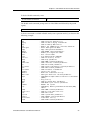
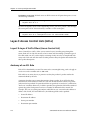
Enable Mode
Enable mode provides more facilities than User mode. You can display critical features
within Enable mode including router configuration, access control lists and SNMP
statistics. To enter Enable mode, enter the enable command, then supply the password
when prompted.
22
SmartSwitch Router User Reference Manual
Chapter 1: SmartSwitch Router Product Overview
To list the Enable commands, enter:
List the Enable commands.
?
The Enable mode command prompt consists of the SSR name followed by the pound
sign(#):
ssr#
To list the commands available in Enable mode, enter a question mark (?) as shown in the
following example:
ssr# ?
acl
aging
arp
cli
configure
copy
dvmrp
enable
exit
file
filters
http
igmp
interface
ip
ip-router
ipx
l2-tables
logout
mtrace
multicast
ospf
-
ping
port
qos
reboot
rip
-
snmp
statistics
stp
system
tacacs
traceroute
vlan
-
SmartSwitch Router User Reference Manual
Show L3 Access Control List
Show L2 and L3 Aging information
Show or modify ARP entries
Modify the command line interface behavior
Enter Configuration Mode
Copy configuration database
Show DVMRP related parameters
Enable privileged user mode
Exit current mode
File manipulation commands
Show L2 security filters
Show http parameters
Show IGMP related parameters
Show interface related parameters
Show IP related parameters
Show unicast IP Routing related parameters
Show IPX related parameters
Show L2 Tables information
Log off the system
Multicast Traceroute utility
Configure Multicast related parameters
Show/Monitor Open Shortest Path First Protocol
(OSPF).
Ping utility
Show or change Port parameters
Show Quality of Service parameters
Reboot the system
Show/Query Routing Information Protocol(RIP)
tables
Show SNMP related parameters.
Show or clear SSR statistics
Show STP status
Show system-wide parameters
Show TACACS related parameters
Traceroute utility
Show VLAN-related parameters
23
Chapter 1: SmartSwitch Router Product Overview
To exit Enable mode and return to User mode, use one of the following commands:
Exit Enable mode.
exit
Ctrl+Z
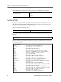
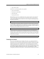
Configure Mode
Configure mode provides the capabilities to configure all features and functions on the
SSR. You can configure features and functions within Configure mode including router
configuration, access control lists and spanning tree.
To list the Configure commands, enter:
List the Configure commands.
?
The Configure mode command prompt consists of the SSR name followed by the pound
sign (#):
ssr(config)#
To list the commands available in Configure mode, enter a question mark (?) as shown in
the following example:
ssr(config)# ?
acl
acl-edit
aging
arp
bgp
cli
dvmrp
exit
filters
http
igmp
interface
ip
ip-router
ipx
ospf
port
qos
rip
snmp
stp
system
24
-
Configure L3 Access Control List
Edit an ACL in the ACL Editor
Configure L2 and L3 Aging
Configure ARP entries
Configure Border Gateway Protocol (BGP)
Modify the command line interface behavior
Configure DVMRP related parameters
Exit current mode
Configure L2 security filters
Configure SNMP related parameters.
Configure IGMP related parameters
Configure interface related parameters
Configure IP related parameters
Configure Unicast Routing Protocol related
parameters
Configure IPX related parameters
Configure Open Shortest Path Protocol (OSPF)
Configure Port parameters
Configure Quality of Service parameters
Configure Routing Information Protocol (RIP)
Configure SNMP related parameters.
Configure STP parameters
Configure system-wide parameters
SmartSwitch Router User Reference Manual
Chapter 1: SmartSwitch Router Product Overview
tacacs
vlan
- Configure TACACS related parameters
- Configure VLAN-related parameters
Special configuration mode commands:
erase
- Erase configuration information
negate
- Negate a command or a group of commands
using line numbers
no
- Negate matching commands
save
- Save configuration information
search
- Look up a command in configuration
show
- Show configuration commands
To exit Configure mode and return to Enable mode, use one of the following commands:
Exit Configure mode.
exit
Ctrl+Z
Boot PROM Mode
If your SSR does not find a valid system image on the external PCMCIA flash, the system
might enter programmable read-only memory (PROM) mode. You should then reboot the
SSR at the boot PROM to restart the system. If the system fails to reboot successfully,
please call Cabletron Systems Technical Support to resolve the problem.
To reboot the SSR from the ROM monitor mode, enter the following command.
Reboot in Boot PROM mode.
reboot
Disabling a Function or Feature
The CLI provides for an implicit negate. This allows for the “disabling” of a feature or
function which has been “enabled”. Use the negate command on a specific line of the
active configuration to “disable” a feature or function which has been enabled. For
example, Spanning Tree Protocol is disabled by default. If after enabling Spanning Tree
Protocol on the SmartSwitch Router, you want to disable STP, you must specify the negate
command on the line of the active configuration containing the stp enable command.
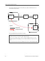
Loading System Images and Configuration Files
The SSR contains an internal flash on the Control Module and an external PC flash. The
internal flash contains the SSR boot image and user defined configuration files. An
external PC flash contains the system image executed by the Control module. When an
SmartSwitch Router User Reference Manual
25
Chapter 1: SmartSwitch Router Product Overview
SSR boots, the boot image is executed first, followed by the system image and finishing
with a configuration file.
Boot and System Image
Only one boot image exists on the internal flash of the SSR Control Module. Multiple
system images can be stored on the external PC flash.
Configuration Files
The SSR uses three special configuration files:
•
Active – The commands from the Startup configuration file and any configuration
commands that you have made active from the scratchpad (see below).
Caution: The active configuration remains in effect only during the current power cycle. If
you power down or reboot the SSR without saving the active configuration changes to the
Startup configuration file, the changes are lost.
•
Startup – The configuration file that the SSR uses to configure itself when the system
is powered on.
•
Scratchpad – The configuration commands you have entered during a management
session. These commands do not become active until you explicitly activate them.
Because some commands depend on other commands for successful execution, the
SSR scratchpad simplifies system configuration by allowing you to enter configuration
commands in any order, even when dependencies exist. When you activate the
commands in the scratchpad, the SSR sorts out the dependencies and executes the
command in the proper sequence.
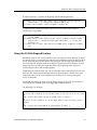
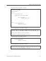
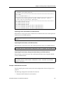
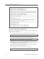
Loading System Image Software
By default, the SSR boots using the system image software installed on the Control
Module’s PCMCIA flash card. To upgrade the system software and boot using the
upgraded image, use the following procedure.
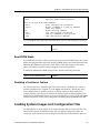
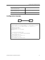
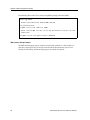
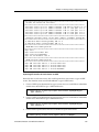
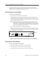
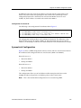
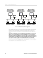
1.
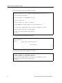
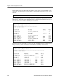
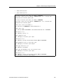
Display the current boot settings by entering the system show version command:
Here is an example:
ctron-ssr-1# system show version
Software Information
Software Version
: 1.0
Copyright
: Copyright (c) 1996-1998 Cabletron Systems, Inc.
Image Information : Version 1.0, built on Fri Mar 20 19:28:49 1998
Image Boot Location: file:/pc-flash/boot/ssr8/
26
SmartSwitch Router User Reference Manual
Chapter 1: SmartSwitch Router Product Overview
Note:
In this example, the location “pc-flash” indicates that the SSR is set to use the
factory-installed software on the flash card.
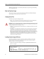
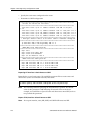
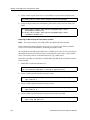
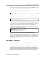
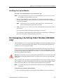
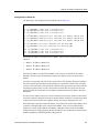
2.
Copy the software upgrade you want to install onto a TFTP server that the SSR can
access. (Use the ping command to verify that the SSR can reach the TFTP server.)
3.
Use the system image add command to copy the software upgrade onto the PCMCIA
flash card in the Control Module.
Here is an example:
ctron-ssr-1# system image add 10.50.11.12 ssr8000
Downloading image 'ssr8000' from host '10.50.11.12'
to local image ssr8000 (takes about 3 minutes)
kernel: 100%
Image checksum validated.
Image added.
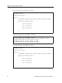
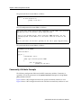
4.
Enter the system image list command to list the images on the PCMCIA flash card
and verify that the new image is on the card:
Here is an example:
ctron-ssr-1# system image list
Images currently available:
ssr8-1.0
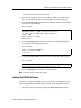
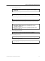
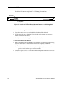
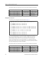
5.
Use the system image choose command to select the image file the SSR will use the
next time you reboot the switch.
Here is an example:
ctron-ssr-1# system image choose ssr8000_10A9
Making image ssr8-1.0 the active image for next reboot
6.
Enter the system image list command to verify the change.
Note:
You do not need to activate this change.
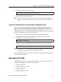
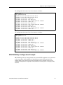
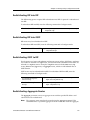
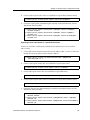
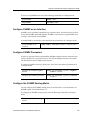
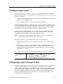
Loading Boot PROM Software
The SSR boots using the boot PROM software installed on the Control Module’s internal
memory. To upgrade the boot PROM software and boot using the upgraded image, use
the following procedure.
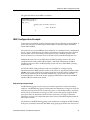
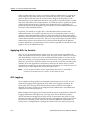
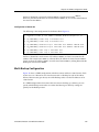
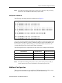
1.
Display the current boot settings by entering the system show version command:
SmartSwitch Router User Reference Manual
27
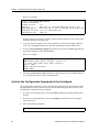
Chapter 1: SmartSwitch Router Product Overview
Here is an example:
ctron-ssr-1# system show version
Software Information
Software Version
: 1.0
Copyright
: Copyright (c) 1996-1998 Cabletron Systems, Inc.
Image Information : Version 1.0.B.13, built on Wed Mar 25 22:49:07 1998
Image Boot Location: file:/pc-flash/boot/ssr8/
Boot Prom Version : prom-1.0
In this example, the location “pc-flash” indicates that the SSR is set to use the factoryinstalled software on the flash card.
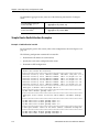
2.
Copy the software upgrade you want to install onto a TFTP server that the SSR can
access. (Use the ping command to verify that the SSR can reach the TFTP server.)
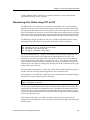
3.
Use the system promimage upgrade command to copy the boot PROM upgrade onto
the internal memory in the Control Module.
Here is an example:
ctron-ssr-1# system promimage upgrade 10.50.11.12 prom2
Downloading image 'prom2' from host '10.50.11.12'
to local image prom2 (takes about 3 minutes)
kernel: 100%
Image checksum validated.
Image added.
4.
Enter the system show version command to verify that the new boot PROM software
is on the internal memory of the Control Module:
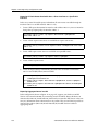
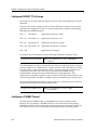
Activate the Configuration Commands in the Scratchpad
The configuration commands you have entered using procedures in this chapter are in the
Scratchpad but have not yet been activated. Use the following procedure to activate the
configuration commands in the scratchpad.
1.
If you have not already done so, enter the enable command to enter Enable mode in
the CLI.
2.
If you have not already done so, enter the configure command to enter Configure
mode in the CLI.
3.
Enter the following command:
save active
28
SmartSwitch Router User Reference Manual
Chapter 1: SmartSwitch Router Product Overview
4.
The CLI displays the following message:
Do you want to make the changes Active? [y]
5.
Enter yes or y to activate the changes.
Note:
If you exit Configure mode (by entering the exit command or pressing Ctrl+Z),
the CLI will ask you whether you want to make the changes in the scratchpad
active.
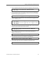
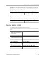
Copy the Configuration to the Startup Configuration File
After you save the configuration commands in the scratchpad, the Control Module
executes the commands and makes the corresponding configuration changes to the SSR.
However, if you power down or reboot the SSR, the new changes are lost. Use the
following procedure to save the changes into the Startup configuration file so that the SSR
reinstates the changes when you reboot the software.
1.
Ensure that you are in the Enable mode by entering the enable command.
2.
Enter the following command to copy the configuration changes in the Active
configuration to the Startup configuration:
copy active to startup
3.
When the CLI displays the following message, enter yes or y to save the changes.
Are you sure you want to overwrite the Startup configuration? [n]
Note:
You also can save active changes to the Startup configuration file from within
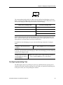
Configure mode by entering the save startup command:
The new configuration changes are added to the Startup configuration file stored in the
Control Module’s boot flash.
Managing the SSR
The SSR contains numerous system facilities for system management. You can perform
configuration management tasks on the SSR including:
•
Setting the SSR name
•
Setting the SSR date and time
•
Configuring the CLI
•
Configuring SNMP services
SmartSwitch Router User Reference Manual
29
Chapter 1: SmartSwitch Router Product Overview
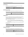
Set SSR Name
The SSR name is set to ssr by default. You may customize the name for the SSR by
entering the following command in Configure mode:.
Set the SSR name.
system set name <system-name>
Set SSR Date and Time
The SSR system time can keep track of time as entered by the user or via NTP. To
configure the SSR date and time manually, enter the following command in Enable mode:
Set SSR date and time.
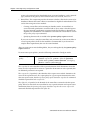
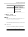
system set date year <year> month <month>
day <day> hour <hour> min <min> second <sec>
Configure NTP
You can use the ntp set server command to instruct the SSR’s NTP client to periodically
synchronize its clock. By default, the SSR specifies an NTPv3 client that sends a
synchronization packet to the server every 60 minutes. This means the SSR will attempt to
set its own clock against the server once every hour. The synchronization interval as well
as the NTP version number can be changed.
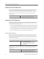
Note:
To ensure that NTP has the correct time, you need to specify the time zone, as
well. You can set the time zone by using the system set timezone command.
When specifying daylight saving time, you’ll need to use the system set daylightsaving command.
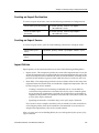
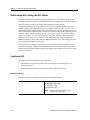
To configure the SSR’s NTP client to synchronize its clock, enter the following command
in Configure mode:
Instruct SSR’s NTP server to
periodically synchronize clock
ntp set server <host> [interval <minutes>]
[source <ipaddr>] [version <num>]
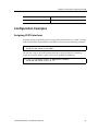
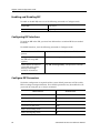
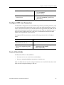
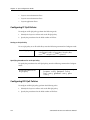
Configure the SSR CLI
You can customize the CLI display format to a desired line length or row count. To
configure the CLI terminal display, enter the following command in Enable mode:
Configure the CLI terminal display.
cli set terminal rows <num> columns
<num>
30
SmartSwitch Router User Reference Manual
Chapter 1: SmartSwitch Router Product Overview
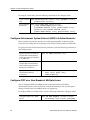
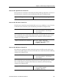
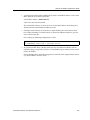
Configure SNMP Services
The SSR accepts SNMP sets and gets from an SNMP manager. You can configure SSR
SNMP parameters including community strings and trap server target addresses.
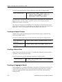
To configure the SSR SNMP community string, enter the following command in
Configure mode:
Configure the SNMP community string.
snmp set community <community-name>
privilege read|read-write
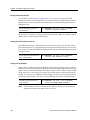
To configure the SNMP trap server target address, enter the following command in
Configure mode:
Configure the SNMP trap server
target address.
snmp set target <IP-addr> community
<community-name> [status
enable|disable]
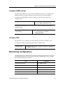
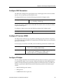
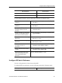
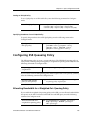
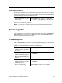
Configure DNS
The SSR allows you to configure up to three Domain Name Service (DNS) servers.
To configure the DNS, the following command in Configure mode.
Configure DNS.
system set dns server <IPaddr>[, <IPaddr>[, <IPaddr>]]
domain <name>
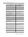
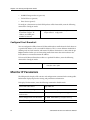
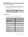
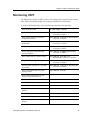
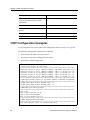
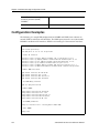
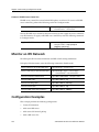
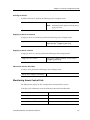
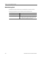
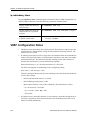
Monitoring Configuration
The SSR provides many commands for displaying configuration information. After you
add configuration items and commit them to the active configuration, you can display
them using the following commands.
Task
Command
Display history buffer.
cli show history
Show terminal settings.
cli show terminal
Show all accesses to the SNMP agent.
snmp show access
Show all SNMP information.
snmp show all
Show chassis ID.
snmp show chassis-id
SmartSwitch Router User Reference Manual
31
Chapter 1: SmartSwitch Router Product Overview
Task
32
Command
Show the SNMP community strings.
snmp show community
Show SNMP related statistics.
snmp show statistics
Show trap target related configuration.
snmp show trap
Show the active configuration of the system.
system show active-config
Show the contents of the boot log file, which
contains all the system messages generated
during bootup.
system show bootlog
Show the most recent Syslog messages kept in
the local syslog message buffer.
system show syslog buffer
Show the contact information (administrator
name, phone number, and so on).
system show contact
Show the SSR date and time.
system show date
Show the IP addresses and domain names for
DNS servers.
system show dns
Show SSR hardware information.
system show hardware
Show SSR location.
system show location
Show SSR name.
system show name
Show the type of Power-On Self Test (POST)
that should be performed.
system show poweron-selftestmode
Show the configuration changes in the
scratchpad. These changes have not yet been
activated.
system show scratchpad
Show the startup configuration for the next
reboot.
system show startup-config
Show the IP address of the SYSLOG server
and the level of messages the SSR sends to the
server.
system show syslog
Lists the last five Telnet connections to the
SSR.
system show telnet-access
Show the default terminal settings (number of
rows, number of columns, and baud rate.
system show terminal
Show SSR uptime.
system show uptime
Show the software version running on the
SSR.
system show version
SmartSwitch Router User Reference Manual
Chapter 2
Bridging
Configuration
Guide
Bridging Overview
The SmartSwitch Router provides the following bridging functions:
•
Complies with the IEEE 802.1d standard
•
Complies with the IGMP multicast bridging standard
•
Provides wire-speed address-based bridging or flow-based bridging
•
Provides the ability to logically segment a transparently bridged network into virtual
local-area networks (VLANs) based on physical ports or protocol (IP or IPX or bridged
protocols like Appletalk)
•
Allows frame filtering based on MAC address for bridged and multicast traffic
•
Provides integrated routing and bridging, which supports bridging of intra-VLAN
traffic and routing of inter-VLAN traffic
Spanning Tree (IEEE 802.1d)
Spanning tree (IEEE 802.1d) allows bridges to dynamically discover a subset of the
topology that is loop-free. In addition, the loop-free tree that is discovered contains paths
to every LAN segment.
SmartSwitch Router User Reference Manual
33
Chapter 2: Bridging Configuration Guide
Note:
WAN interfaces on the SSR do not currently support Spanning Tree operations.
However, future implementations of WAN for the SSR family of routers will
support Spanning Tree.
Bridging Modes (Flow-Based and Address-Based)
The SSR provides the following types of wire-speed bridging:
Address-based bridging - The SSR performs this type of bridging by looking up the
destination address in an L2 lookup table on the line card that receives the bridge packet
from the network. The L2 lookup table indicates the exit port(s) for the bridged packet. If
the packet is addressed to the SSR's own MAC address, the packet is routed rather than
bridged.
Flow-based bridging - The SSR performs this type of bridging by looking up an entry in
the L2 lookup table containing both the source and destination addresses of the received
packet in order to determine how the packet is to be handled.
The SSR ports perform address-based bridging by default but can be configured to
perform flow-based bridging instead, on a per-port basis. A port cannot be configured to
perform both types of bridging at the same time.
The SSR performance is equivalent when performing flow-based bridging or addressbased bridging. However, address-based bridging is more efficient because it requires
fewer table entries while flow-based bridging provides tighter management and control
over bridged traffic.
VLAN Overview
Virtual LANs (VLANs) are a means of dividing a physical network into several logical
(virtual) LANs. The division can be done on the basis of various criteria, giving rise to
different types of VLANs. For example, the simplest type of VLAN is the port-based
VLAN. Port-based VLANs divide a network into a number of VLANs by assigning a
VLAN to each port of a switching device. Then, any traffic received on a given port of a
switch belongs to the VLAN associated with that port.
VLANs are primarily used for broadcast containment. A layer-2 (L2) broadcast frame is
normally transmitted all over a bridged network. By dividing the network into VLANs,
the range of a broadcast is limited, i.e., the broadcast frame is transmitted only to the
VLAN to which it belongs. This reduces the broadcast traffic on a network by an
appreciable factor.
The type of VLAN depends upon one criterion: how a received frame is classified as
belonging to a particular VLAN. VLANs can be categorized into the following types:
•
34
Port based
SmartSwitch Router User Reference Manual
Chapter 2: Bridging Configuration Guide
•
MAC address based
•
Protocol based
•
Subnet based
•
Multicast based
•
Policy based
Detailed information about these types of VLANs is beyond the scope of this manual.
Each type of VLAN is briefly explained in the following subsections.
Port-based VLANs
Ports of L2 devices (switches, bridges) are assigned to VLANs. Any traffic received by a
port is classified as belonging to the VLAN to which the port belongs. For example, if
ports 1, 2, and 3 belong to the VLAN named “Marketing”, then a broadcast frame received
by port 1 is transmitted on ports 2 and 3. It is not transmitted on any other port.
MAC-address-based VLANs
In this type of VLAN, each switch (or a central VLAN information server) keeps track of
all MAC addresses in a network and maps them to VLANs based on information
configured by the network administrator. When a frame is received at a port, its
destination MAC address is looked up in the VLAN database, which returns the VLAN to
which this frame belongs.
This type of VLAN is powerful in the sense that network devices such as printers and
workstations can be moved anywhere in the network without the need for network
reconfiguration. However, the administration is intensive because all MAC addresses on
the network need to be known and configured.
Protocol-based VLANs
Protocol-based VLANs divide the physical network into logical VLANs based on
protocol. When a frame is received at a port, its VLAN is determined by the protocol of
the packet. For example, there could be separate VLANs for IP, IPX and Appletalk. An IP
broadcast frame will only be sent to all ports in the IP VLAN.
Subnet-based VLANs
Subnet-based VLANs are a subset of protocol based VLANs and determine the VLAN of a
frame based on the subnet to which the frame belongs. To do this, the switch must look
into the network layer header of the incoming frame. This type of VLAN behaves similar
to a router by segregating different subnets into different broadcast domains.
SmartSwitch Router User Reference Manual
35
Chapter 2: Bridging Configuration Guide
Multicast-based VLANs
Multicast-based VLANs are created dynamically for multicast groups. Typically, each
multicast group corresponds to a different VLAN. This ensures that multicast frames are
received only by those ports that are connected to members of the appropriate multicast
group.
Policy-based VLANs
Policy-based VLANs are the most general definition of VLANs. Each incoming
(untagged) frame is looked up in a policy database, which determines the VLAN to which
the frame belongs. For example, you could set up a policy which creates a special VLAN
for all email traffic between the management officers of a company, so that this traffic will
not be seen anywhere else.
SSR VLAN Support
The SSR supports:
•
Port-based VLANs
•
Protocol-based VLANs
•
Subnet-based VLANs
When using the SSR as an L2 bridge/switch, use the port-based and protocol-based
VLAN types. When using the SSR as a combined switch and router, use the subnet-based
VLANs in addition to port-based and protocol-based VLANs. It is not necessary to
remember the types of VLANs in order to configure the SSR, as seen in the section on
configuring the SSR.
VLANs and the SSR
VLANs are an integral part of the SSR family of switching routers. The SSR switching
routers can function as layer-2 (L2) switches as well as fully-functonal layer-3 (L3) routers.
Hence they can be viewed as a switch and a router in one box. To provide maximum
performance and functionality, the L2 and L3 aspects of the SSR switching routers are
tightly coupled.
The SSR can be used purely as an L2 switch. Frames arriving at any port are bridged and
not routed. In this case, setting up VLANs and associating ports with VLANs is all that is
required. You can set up the SSR switching router to use port-based VLANs, protocolbased VLANs, or a mixture of the two types.
The SSR can also be used purely as a router, i.e., each physical port of the SSR is a separate
routing interface. Packets received at any interface are routed and not bridged. In this
case, no VLAN configuration is required. Note that VLANs are still created implicitly by
36
SmartSwitch Router User Reference Manual
Chapter 2: Bridging Configuration Guide
the SSR as a result of creating L3 interfaces for IP and/or IPX. However, these implicit
VLANs do not need to be created or configured manually. The implicit VLANs created by
the SSR are subnet-based VLANs.
Most commonly, an SSR is used as a combined switch and router. For example, it may be
connected to two subnets S1 and S2. Ports 1-8 belong to S1 and ports 9-16 belong to S2.
The required behavior of the SSR is that intra-subnet frames be bridged and inter-subnet
packets be routed. In other words, traffic between two workstations that belong to the
same subnet should be bridged, and traffic between two workstations that belong to
different subnets should be routed.
The SSR switching routers use VLANs to achieve this behavior. This means that a L3
subnet (i.e., an IP or IPX subnet) is mapped to a VLAN. A given subnet maps to exactly
one and only one VLAN. With this definition, the terms VLAN and subnet are almost
interchangeable.
To configure an SSR as a combined switch and router, the administrator must create
VLANs whenever multiple ports of the SSR are to belong to a particular VLAN/subnet.
Then the VLAN must be bound to an L3 (IP/IPX) interface so that the SSR knows which
VLAN maps to which IP/IPX subnet.
Ports, VLANs, and L3 Interfaces
The term port refers to a physical connector on the SSR, such as an ethernet port. Each
port must belong to at least one VLAN. When the SSR is unconfigured, each port belongs
to a VLAN called the “default VLAN”. By creating VLANs and adding ports to the
created VLANs, the ports are moved from the default VLAN to the newly created VLANs.
Unlike traditional routers, the SSR has the concept of logical interfaces rather than
physical interfaces. An L3 interface is a logical entity created by the administrator. It can
contain more than one physical port. When an L3 interface contains exactly one physical
port, it is equivalent to an interface on a traditional router. When an L3 interface contains
several ports, it is equivalent to an interface of a traditional router which is connected to a
layer-2 device such as a switch or bridge.
Access Ports and Trunk Ports (802.1Q support)
The ports of an SSR can be classified into two types, based on VLAN functionality: access
ports and trunk ports. By default, a port is an access port. An access port can belong to at
most one VLAN of the following types: IP, IPX or bridged protocols. The SSR can
automatically determine whether a received frame is an IP frame, an IPX frame or neither.
Based on this, it selects a VLAN for the frame. Frames transmitted out of an access port
are untagged, meaning that they contain no special information about the VLAN to which
they belong. Untagged frames are classified as belonging to a particular VLAN based on
the protocol of the frame and the VLAN configured on the receiving port for that protocol.
SmartSwitch Router User Reference Manual
37
Chapter 2: Bridging Configuration Guide
For example, if port 1 belongs to VLAN IPX_VLAN for IPX, VLAN IP_VLAN for IP and
VLAN OTHER_VLAN for any other protocol, then an IP frame received by port 1 is
classified as belonging to VLAN IP_VLAN.
Trunk ports (802.1Q) are usually used to connect one VLAN-aware switch to another.
They carry traffic belonging to several VLANs. For example, suppose that SSR A and B
are both configured with VLANs V1 and V2.
Then a frame arriving at a port on SSR A must be sent to SSR B, if the frame belongs to
VLAN V1 or to VLAN V2. Thus the ports on SSR A and B which connect the two SSRs
together must belong to both VLAN V1 and VLAN V2. Also, when these ports receive a
frame, they must be able to determine whether the frame belongs to V1 or to V2. This is
accomplished by “tagging” the frames, i.e., by prepending information to the frame in
order to identify the VLAN to which the frame belongs. In the SSR switching routers,
trunk ports always transmit and receive tagged frames only. The format of the tag is
specified by the IEEE 802.1Q standard. The only exception to this is Spanning Tree
Protocol frames, which are transmitted as untagged frames.
Explicit and Implicit VLANs
As mentioned earlier, VLANs can either be created explicitly by the administrator (explicit
VLANs) or are created implicitly by the SSR when L3 interfaces are created (implicit
VLANs).
Configuring SSR Bridging Functions
Configure Address-based or Flow-based Bridging
The SSR ports perform address-based bridging by default but can be configured to
perform flow-based bridging instead of address-based bridging, on a per-port basis. A
port cannot be configured to perform both types of bridging at the same time.
The SSR performance is equivalent when performing flow-based bridging or addressbased bridging. However, address-based bridging is more efficient because it requires
fewer table entries while flow-based bridging provides tighter management and control
over bridged traffic.
For example, the following illustration shows an SSR with traffic being sent from port A to
port B, port B to port A, port B to port C, and port A to port C.
38
SmartSwitch Router User Reference Manual
Chapter 2: Bridging Configuration Guide
SSR
A
B
C
The corresponding bridge tables for address-based and flow-based bridging are shown
below. As shown, the bridge table contains more information on the traffic patterns when
flow-based bridging enabled compared to address-based bridging.
Address-Based Bridge Table
Flow-Based Bridge Table
A (source)
A→B
B (source)
B→A
C (destination)
B→C
A→C
With the SSR configured in flow-based bridging mode, the network manager has “per
flow” control of layer-2 traffic. The network manager can then apply Quality of Service
(QoS) policies or security filters based layer-2 traffic flows.
To enable flow-based bridging on a port, enter the following command in Configure
Mode.
Configure a port for flow-based
bridging.
port flow-bridging <port-list>|all-ports
To change a port from flow-based bridging to address-based bridging, enter the following
command in Configure mode:
Change a port from flowbased bridging to addressbased bridging.
negate <line-number of active config containing command>:
port flow-bridging <port-list>|all-ports
Configuring Spanning Tree
The SSR supports only one spanning tree process per SSR. By default, spanning tree is
disabled on the SSR. To enable spanning tree on the SSR, you perform the following task
on the ports where you want spanning tree enabled.
SmartSwitch Router User Reference Manual
39
Chapter 2: Bridging Configuration Guide
Note:
If you are running spanning tree on one or more VLANs, you must enable
spanning tree on all ports belonging to each VLAN.
Enable spanning tree on one or
more ports.
stp enable port <port-list>
Adjust Spanning-Tree Parameters
You may need to adjust certain spanning-tree parameters if the default values are not
suitable for your bridge configuration. Parameters affecting the entire spanning tree are
configured with variations of the bridge global configuration command. Interface-specific
parameters are configured with variations of the bridge-group interface configuration
command.
You can adjust spanning-tree parameters by performing any of the tasks in the following
sections:
•
Set the Bridge Priority
•
Set an Interface Priority
Note:
Only network administrators with a good understanding of how bridges and the
Spanning-Tree Protocol work should make adjustments to spanning-tree
parameters. Poorly chosen adjustments to these parameters can have a negative
impact on performance. A good source on bridging is the IEEE 802.1d
specification.
Set the Bridge Priority
You can globally configure the priority of an individual bridge when two bridges tie for
position as the root bridge, or you can configure the likelihood that a bridge will be
selected as the root bridge. The lower the bridge's priority, the more likely the bridge will
be selected as the root bridge. This priority is determined by default; however, you can
change it.
To set the bridge priority, enter the following command in Configure mode:
Set the bridge priority.
stp set bridging priority <num>
Set a Port Priority
You can set a priority for an interface. When two bridges tie for position as the root bridge,
you configure an interface priority to break the tie. The bridge with the lowest interface
value is elected.
40
SmartSwitch Router User Reference Manual
Chapter 2: Bridging Configuration Guide
To set an interface priority, enter the following command in Configure mode:
Establish a priority for a specified
interface.
stp set port <port-list> priority <num>
Assign Port Costs
Each interface has a port cost associated with it. By convention, the port cost is 1000/data
rate of the attached LAN, in Mbps. You can set different port costs.
To assign port costs, enter the following command in Configure mode:
Set a different port cost other than
the defaults.
stp set port <port-list> port-cost <num>
Adjust Bridge Protocol Data Unit (BPDU) Intervals
You can adjust BPDU intervals as described in the following sections:
•
Adjust the Interval between Hello BPDUs
•
Define the Forward Delay Interval
•
Define the Maximum Idle Interval
Adjust the Interval between Hello Times
You can specify the interval between hello time.
To adjust this interval, enter the following command in Configure mode:
Specify the interval between hello
time
stp set bridging hello-time <num>
Define the Forward Delay Interval
The forward delay interval is the amount of time spent listening for topology change
information after an interface has been activated for bridging and before forwarding
actually begins.
To change the default interval setting, enter the following command in Configure mode:
Set the default of the forward delay
interval.
SmartSwitch Router User Reference Manual
stp set bridging forward-delay <num>
41
Chapter 2: Bridging Configuration Guide
Define the Maximum Age
If a bridge does not hear BPDUs from the root bridge within a specified interval, it
assumes that the network has changed and recomputes the spanning-tree topology.
To change the default interval setting, enter the following command in Configure mode:
Change the amount of time a bridge will
wait to hear BPDUs from the root bridge.
stp set bridging max-age <num>
Configuring a Port or Protocol based VLAN
To create a port or protocol based VLAN, perform the following steps in the Configure
mode.
1.
Create a port or protocol based VLAN.
2.
Add physical ports to a VLAN.
Create a Port or Protocol Based VLAN
To create a VLAN, perform the following command in the Configure mode.
Create a VLAN.
vlan create <vlan-name> <type> id <num>
Adding Ports to a VLAN
To add ports to a VLAN, perform the following command in the Configure mode.
Add ports to a VLAN.
vlan add ports <port-list> to <vlan-name>
Configuring VLAN Trunk Ports
The SSR supports standards-based VLAN trunking between multiple SSRs as defined by
IEEE 802.1Q. 802.1Q adds a header to a standard Ethernet frame which includes a unique
VLAN id per trunk between two SSRs. These VLAN ids extend the VLAN broadcast
domain to more than one SSR.
To configure a VLAN trunk, perform the following command in the Configure mode.
Configure 802.1Q VLAN trunks.
42
vlan make <port-type> <port-list>
SmartSwitch Router User Reference Manual
Chapter 2: Bridging Configuration Guide
Configure Bridging for Non-IP/IPX Protocols
By default, all non-routable protocols (AppleTalk and DECnet) are bridged within the
SSR. All physical ports containing non-routable protocols should be assigned to the same
VLAN, thus allowing bridging between ports. Routing can still be performed on the
defined VLAN by assigning an IP or IPX interface.
Configure Layer-2 Filters
Layer-2 security filters on the SSR allow you to configure ports to filter specific MAC
addresses. When defining a Layer-2 security filter, you specify to which ports you want
the filter to apply. Refer to the “Security Configuration Chapter” for details on configuring
Layer-2 filters. You can specify the following security filters:
•
Address filters
These filters block traffic based on the frame's source MAC address, destination MAC
address, or both source and destination MAC addresses in flow bridging mode.
Address filters are always configured and applied to the input port.
•
Port-to-address lock filters
These filters prohibit a user connected to a locked port or set of ports from using
another port.
•
Static entry filters
These filters allow or force traffic to go to a set of destination ports based on a frame's
source MAC address, destination MAC address, or both source and destination MAC
addresses in flow bridging mode. Static entries are always configured and applied at
the input port.
•
Secure port filters
A secure filter shuts down access to the SSR based on MAC addresses. All packets
received by a port are dropped. When combined with static entries, however, these
filters can be used to drop all received traffic but allow some frames to go through.
Monitor Bridging
The SSR provides display of bridging statistics and configurations contained in the SSR.
To display bridging information, enter the following commands in Enable mode.
Show IP routing table.
ip show routes
Show all MAC addresses currently
in the l2 tables.
l2-tables show all-macs
SmartSwitch Router User Reference Manual
43
Chapter 2: Bridging Configuration Guide
Show l2 table information on a
specific port.
l2-tables show port-macs
Show information the master MAC
table.
l2-tables show mac-table-stats
Show information on a specific
MAC address.
l2-tables show mac
Show information on MACs
registered.
l2-table show bridge-management
Show all VLANs.
vlan list
Configuration Examples
Creating an IP or IPX VLAN
VLANs are used to associate physical ports on the SSR with connected hosts that may be
physically separated but need to participate in the same broadcast domain. To associate
ports to a VLAN, you must first create an IP or IPX VLAN and then assign ports to the
VLAN.
For example, servers connected to port gi.1.(1-2) on the SSR need to communicate with
clients connected to et.4.(1-8). You can associate all the ports containing the clients and
servers to an IP VLAN called ‘BLUE’.
First, create an IP VLAN named ‘BLUE’
ssr(config)# vlan create BLUE ip
Next, assign ports to the ‘BLUE’ VLAN.
ssr(config)# vlan add ports et.1.(1-8), gi.1.(1-2) to BLUE
44
SmartSwitch Router User Reference Manual
Chapter 3
IP Routing
Configuration
Guide
This chapter describes how to configure IP interfaces and general non-protocol-specific
routing parameters.
IP Routing Overview
Internet Protocol (IP) is a packet-based protocol used to exchange data over computer
networks. IP handles addressing, routing, fragmentation, reassembly, and protocol
demultiplexing. In addition, IP specifies how hosts and routers should process packets,
handle errors and discard packets. IP forms the foundation upon which transport layer
protocols, such as TCP or UDP, interoperate over a routed network.
The Transmission Control Protocol (TCP) is built upon the IP layer. TCP is a connectionoriented protocol that specifies the data format, buffering and acknowledgments used in
the transfer of data. TCP is a full-duplex connection which also specifies the procedures
that the computers use to ensure that the data arrives correctly.
The User Datagram Protocol (UDP) provides the primary mechanism that applications
use to send datagrams to other application programs. UDP is a connectionless protocol
that does not guarantee delivery of datagrams between applications. Applications which
use UDP are responsible for ensuring successful data transfer by employing error
handling, retransmission and sequencing techniques.
TCP and UDP also specify “ports,” which identify the application which is using
TCP/UDP. For example, a web server would typically use TCP/UDP port 80, which
specifies HTTP-type traffic.
SmartSwitch Router User Reference Manual
45
Chapter 3: IP Routing Configuration Guide
The SSR supports standards based TCP, UDP, and IP.
IP Routing Protocols
The SSR supports standards based unicast and multicast routing. Unicast routing protocol
support include Interior Gateway Protocols and Exterior Gateway Protocols. Multicast
routing protocols are used to determine how multicast data is transferred in a routed
environment.
Unicast Routing Protocols
Interior Gateway Protocols are used for routing networks that are within an “autonomous
system,” a network of relatively limited size. All IP interior gateway protocols must be
specified with a list of associated networks before routing activities can begin. A routing
process listens to updates from other routers on these networks and broadcasts its own
routing information on those same networks. The SSR supports the following Interior
Gateway Protocols:
•
Routing Information Protocol (RIP) Version 1, 2 (RFC 1058, 1723)
•
Open Shortest Path First (OSPF) Version 2 (RFC 1583)
Exterior Gateway Protocols are used to transfer information between different
“autonomous systems”. The SSR supports the following Exterior Gateway Protocol:
•
Border Gateway Protocol (BGP) Version 3, 4 (RFC 1267, 1771)
Multicast Routing Protocols
IP multicasting allows a host to send traffic to a subset of all hosts. These hosts subscribe
to group membership, thus notifying the SSR of participation in a multicast transmission.
Multicast routing protocols are used to determine which routers have directly attached
hosts, as specified by IGMP, that have membership to a multicast session. Once host
memberships are determined, routers use multicast routing protocols, such as DVMRP, to
forward multicast traffic between routers.
The SSR supports the following multicast routing protocols:
•
Distance Vector Multicast Routing Protocol (DVMRP) RFC 1075
•
Internet Group Management Protocol (IGMP) as described in RFC 2236
The SSR also supports the latest DVMRP Version 3.0 draft specification, which includes
mtrace, Generation ID and Pruning/Grafting.
46
SmartSwitch Router User Reference Manual
Chapter 3: IP Routing Configuration Guide
Configuring IP Interfaces and Parameters
This section provides an overview of configuring various IP parameters and setting up IP
interfaces.
Configure IP Addresses to Ports
You can configure one IP interface directly to physical ports. Each port can be assigned
multiple IP addresses representing multiple subnets connected to the physical port.
To configure an IP interface to a port, enter one of the following commands in Configure
mode.
Configure an IP interface to a
physical port.
interface create ip <InterfaceName>
address-mask <ipAddr-mask> port <port>
Configure a secondary address to
an existing IP interface.
interface add ip <InterfaceName>
address-netmask <ipAddr-mask>
[broadcast <ipaddr>]
Configure IP Interfaces for a VLAN
You can configure one IP interface per VLAN. Once an IP interface has been assigned to a
VLAN, you can add a secondary IP addresses to the VLAN.
To configure a VLAN with an IP interface, enter the following command in Configure
mode:
Create an IP interface for a VLAN.
interface create ip <InterfaceName>
address-mask <ipAddr-mask> vlan <name>
Configure a secondary address to
an existing VLAN.
interface add ip <InterfaceName>
address-netmask <ipAddr-mask>
vlan <name>
Specify Ethernet Encapsulation Method
The SmartSwitch Router supports two encapsulation types for IP. You can configure
encapsulation type on a per-interface basis.
•
Ethernet II: The standard ARPA Ethernet Version 2.0 encapsulation, which uses a 16bit protocol type code (the default encapsulation method)
SmartSwitch Router User Reference Manual
47
Chapter 3: IP Routing Configuration Guide
•
802.3 SNAP: SNAP IEEE 802.3 encapsulation, in which the type code becomes the
frame length for the IEEE 802.2 LLC encapsulation (destination and source Service
Access Points, and a control byte)
To configure IP encapsulation, enter one of the following commands in Configure mode.
Configure Ethernet II
encapsulation.
interface create ip <InterfaceName> output-macencapsulation ethernet_II
Configure 802.3
SNAP encapsulation.
interface create ip <InterfaceName> output-macencapsulation ethernet_snap
Configure Address Resolution Protocol
The SSR allows you to configure Address Resolution Protocol (ARP) table entries and
parameters. ARP is used to associate IP addresses with media or MAC addresses. Taking
an IP address as input, ARP determines the associated MAC address. Once a media or
MAC address is determined, the IP address/media address association is stored in an
ARP cache for rapid retrieval. Then the IP datagram is encapsulated in a link-layer frame
and sent over the network.
Configure ARP Cache Entries
You can add and delete entries in the ARP cache. To add or delete static ARP entries, enter
one of the the following commands in Configure mode:
Add a static ARP entry.
arp add <host> mac-addr <MAC-addr>
exit-port <port>
Clear a static ARP entry.
arp clear <host>
Configure Proxy ARP
The SSR can be configured for proxy ARP. The SSR uses proxy ARP (as defined in
RFC 1027) to help hosts with no knowledge of routing determine the MAC address of
hosts on other networks or subnets. Through Proxy ARP, the SSR will respond to ARP
requests from a host with a ARP reply packet containing the SSR MAC address. Proxy
ARP is enabled by default on the SSR.
To disable proxy ARP, enter the following command in Configure mode:
Disable Proxy ARP on
an interface.
48
ip disable-proxy-arp interface <InterfaceName>|all
SmartSwitch Router User Reference Manual
Chapter 3: IP Routing Configuration Guide
Configure DNS Parameters
The SSR can be configured to specify DNS servers which supply name services for DNS
requests. You can specify up to three DNS servers.
To configure DNS servers, enter the following command in Configure mode:
Configure a DNS server.
system set dns server <IPaddr>
[, <IPaddr>[, <IPaddr>]]
You can also specify a domain name for the SSR. The domain name is used by the SSR to
respond to DNS requests.
To configure a domain name, enter the following command in Configure mode:
Configure a domain name.
system set dns domain <name>
Configure IP Services (ICMP)
The SSR provides ICMP message capabilities including ping and traceroute. Ping allows
you to determine the reachability of a certain IP host. Traceroute allows you to trace the IP
gateways to an IP host.
To access ping or traceroute on the SSR, enter the following commands in Enable mode:
Specify ping.
ping <hostname-or-IPaddr> packets <num> size <num>
wait <num> [flood] [dontroute]
Specify traceroute.
traceroute <host> [max-ttl <num>] [probes <num>]
[size <num>] [source <secs>] [tos <num>]
[wait-time <secs>] [verbose] [noroute]
Configure IP Helper
You can configure the SSR to forward UDP broadcast packets recieved on a given interface
to a specified IP address. You can specify a UDP port number for which UDP broadcast
packets with that destination port number will be forwarded. By default, if no UDP port
number is specified, the SSR will forward UDP broadcast packets for the following six
services:
•
BOOTP/DHCP (port 67 and 68)
•
DNS (port 37)
•
NetBIOS Name Server (port 137)
SmartSwitch Router User Reference Manual
49
Chapter 3: IP Routing Configuration Guide
•
NetBIOS Datagram Server (port 138)
•
TACACS Server (port 49)
•
Time Service (port 37)
To configure a destination to which UDP packets will be forwarded, enter the following
command in Configure mode:
Specify local subnet interface,
destination “helper” IP
address, and UDP port
number to forward
ip helper-address interface <interface-name>
<helper-address> <udp-port#>
Configure Direct Broadcast
You can configure the SSR to forward all directed broadcast traffic from the local subnet to
a specified IP address or all associated IP addresses. This is a more efficient method than
defining only one local interface and remote IP address destination at a time with the iphelper command when you are forwarding traffic from more than one interface in the
local subnet to a remote destination IP address.
To forward all directed broadcast traffic to a specified IP address, enter the following
command in Configure mode:
Forward directed broadcast traffic
ip enable directed-broadcast interface
<interface name>|all
Monitor IP Parameters
The SSR provides display of IP statistics and configurations contained in the routing table.
Information displayed provides routing and performance information.
To display IP information, enter the following command in Enable mode:
50
Show ARP table entries.
arp show all
Show IP interface configuration
interface show ip
Show all TCP/UDP connections
and services.
ip show connections [no-lookup]
Show configuration of IP interfaces.
ip show interfaces [<interface-name>]
Show IP routing table information.
ip show routes
SmartSwitch Router User Reference Manual
Chapter 3: IP Routing Configuration Guide
Show ARP entries in routing table.
ip show routes show-arps
Show DNS parameters.
system show dns
Configuration Examples
Assigning IP/IPX Interfaces
To enable routing on the SSR, you must assign an IP or IPX interface to a VLAN. To assign
an IP or IPX interface named ‘RED’ to the ‘BLUE’ VLAN, enter the following command:
ssr(config)# interface create ip RED address-netmask
10.50.0.1/255.255.0.0 vlan BLUE
You can also assign an IP or IPX interface directly to a physical port. For example, to
assign an IP interface ‘RED’ to physical port et.3.4, perform the following:
ssr(config)# interface create ip RED address-netmask
10.50.0.0/255.255.0.0 port et.3.4
SmartSwitch Router User Reference Manual
51
Chapter 3: IP Routing Configuration Guide
52
SmartSwitch Router User Reference Manual
Chapter 4
RIP Configuration
Guide
RIP Overview
This chapter describes how to configure Routing Information Protocol (RIP) in the
SmartSwitch Router. RIP is a distance-vector routing protocol for use in small networks.
RIP is described in RFC 1723. A router running RIP broadcasts updates at set intervals.
Each update contains paired values where each pair consists of an IP network address and
an integer distance to that network. RIP uses a hop count metric to measure the distance
to a destination.
The SmartSwitch Router provides support for RIP Version 1 and 2. The SSR implements
plain text and MD5 authentication methods for RIP Version 2.
The protocol independent features that apply to RIP are described in Chapter 3: “IP
Routing Configuration Guide” on page 45.
Configure RIP
By default, RIP is disabled on the SSR and on each of the attached interfaces. To configure
RIP on the SSR, follow these steps:
1.
Start the RIP process by entering the rip start command.
2.
Use the rip add interface command to inform RIP about the attached interfaces.
SmartSwitch Router User Reference Manual
53
Chapter 4: RIP Configuration Guide
Enabling and Disabling RIP
To enable or disable RIP, enter one of the following commands in Configure mode.
Enable RIP.
rip start
Disable RIP.
rip stop
Configuring RIP Interfaces
To configure RIP in the SSR, you must first add interfaces to inform RIP about attached
interfaces.
To add RIP interfaces, enter the following commands in Configure mode.
Add interfaces to the RIP
process.
rip add interface <interfacename-or-IPaddr>
Add gateways from which
the SSR will accept RIP
updates.
rip add trusted-gateway <interfacename-or-IPaddr>
Define the list of routers to
which RIP sends packets
directly, not through
multicast or broadcast.
rip add source-gateway <interfacename-or-IPaddr>
Configure RIP Parameters
No further configuration is required and the system default parameters will be used by
RIP to exchange routing information. These default parameters may be modified to suit
your needs by using the rip set interface command.
RIP Parameter
54
Default Value
Version number
RIP v1
Check-zero for RIP reserved parameters
Enabled
Whether RIP packets should be broadcast
Choose
Preference for RIP routes
100
Metric for incoming routes
1
Metric for outgoing routes
0
SmartSwitch Router User Reference Manual
Chapter 4: RIP Configuration Guide
RIP Parameter
Default Value
Authentication
None
Update interval
30 seconds
To change RIP parameters, enter the following commands in Configure mode.
Set RIP Version on an interface
to RIP V1.
rip set interface <interfacename-or-IPaddr>|all
version 1
Set RIP Version on an interface
to RIP V2.
rip set interface <interfacename-or-IPaddr>|all
version 2
Specify that RIP V2 packets
should be multicast on this
interface.
rip set interface <interfacename-or-IPaddr>|all
type multicast
Specify that RIP V2 packets that
are RIP V1-compatible should
be broadcast on this interface.
rip set interface <interfacename-or-IPaddr>|all
type broadcast
Change the metric on incoming
RIP routes.
rip set interface <interfacename-or-IPaddr>|all
metric-in <num>
Change the metric on outgoing
RIP routes.
rip set interface <interfacename-or-IPaddr>|all
metric-out <num>
Set the authentication method
to simple text up to 8
characters.
rip set interface <interfacename-or-IPaddr>|all
authentication-method simple
Set the authentication method
to MD5.
rip set interface <interfacename-or-IPaddr>|all
authentication-method md5
Specify the metric to be used
when advertising routes that
were learned from other
protocols.
rip set default-metric <num>
Configure RIP Route Preference
You can set the preference of routes learned from RIP.
To configure RIP route preference, enter the following command in Configure mode.
Set the preference of routes learned from RIP.
SmartSwitch Router User Reference Manual
rip set preference <num>
55
Chapter 4: RIP Configuration Guide
Configure RIP Route Default-Metric
You can define the metric used when advertising routes via RIP that were learned from
other protocols. The default value for this parameter is 16 (unreachable). To export routes
from other protocols into RIP, you must explicitly specify a value for the default-metric
parameter. The metric specified by the default-metric parameter may be overridden by a
metric specified in the export command.
To configure default-metric, enter the following command in Configure mode.
Define the metric used when advertising routes
via RIP that were learned from other protocols.
rip set default-metric <num>
For <num>, you must specify a number between 1 and 16.
Monitoring RIP
The rip trace command can be used to trace all rip request and response packets.
To monitor RIP information, enter the following commands in Enable mode.
56
Show all RIP information.
rip show all
Show RIP export policies.
rip show export-policy
Show RIP global information.
rip show globals
Show RIP import policies.
rip show import-policy
Show RIP information on the specified
interface.
rip show interface <Name or IP-addr>
Show RIP interface policy information.
rip show interface-policy
Show detailed information of all RIP
packets
rip trace packets detail
Show detailed information of all packets
received by the router.
rip trace packets receive
Show detailed information of all packets
sent by the router.
rip trace packets send
Show detailed information of all request
received by the router.
rip trace request receive
Show detailed information of all response
received by the router.
rip trace response receive
SmartSwitch Router User Reference Manual
Chapter 4: RIP Configuration Guide
Show detailed information of response
packets sent by the router.
rip trace response send
Show detailed information of request
packets sent by the router.
rip trace send request
Show RIP timer information.
rip show timers
Configuration Example
SSR 1
SSR 2
Interface 1.1.1.1
Interface 3.2.1.1
! Example configuration
!
! Create interface ssr1-if1 with ip address 1.1.1.1/16 on port et.1.1 on SSR-1
interface create ip ssr1-if1 address-netmask 1.1.1.1/16 port et.1.1
!
! Configure rip on SSR-1
rip add interface ssr1-if1
rip set interface ssr1-if1 version 2
rip start
!
!
! Set authentication method to md5
rip set interface ssr1-if1 authentication-method md5
!
! Change default metric-in
rip set interface ssr1-if1 metric-in 2
!
! Change default metric-out
rip set interface ssr1-if1 metric-out 3
SmartSwitch Router User Reference Manual
57
Chapter 4: RIP Configuration Guide
58
SmartSwitch Router User Reference Manual
Chapter 5
OSPF
Configuration
Guide
OSPF Overview
Open Shortest Path First (OSPF) is a link-state routing protocol that supports IP
subnetting and authentication. The SSR supports OSPF Version 2.0 as defined in RFC
1583. Each link-state message contains all the links connected to the router with a
specified cost associated with the link.
The SSR supports the following OSPF functions:
•
Stub Areas: Definition of stub areas is supported
•
Authentication: Simple password and MD5 authentication methods are supported
within an area
•
Virtual Links: Virtual links are supported
•
Route Redistribution: Routes learned via RIP, BGP, or any other sources can be
redistributed into OSPF. OSPF routes can be redistributed into RIP or BGP
•
Interface Parameters: Parameters that can be configured include interface output cost,
retransmission interval, interface transmit delay, router priority, router dead and hello
intervals, and authentication key
SmartSwitch Router User Reference Manual
59
Chapter 5: OSPF Configuration Guide
OSPF Multipath
The SSR also supports OSPF and static Multi-path. If multiple equal-cost OSPF or static
routes have been defined for any destination, then the SSR “discovers” and uses all of
them. The SSR will automatically learn up to four equal-cost OSPF or static routes and
retain them in its forwarding information base (FIB). The forwarding module then installs
flows for these destinations in a round-robin fashion.
Configure OSPF
To configure OSPF on the SSR, you must enable OSPF, create OSPF areas, assign interfaces
to OSPF areas, and, if necessary, specify any of the OSPF interface parameters.
To configure OSPF, you may need to perform some or all of the following tasks:
•
Enable OSPF.
•
Create OSPF areas.
•
Create an IP interface or assign an IP interface to a VLAN.
•
Add IP interfaces to OSPF areas.
•
Configure OSPF interface parameters, if necessary.
Note:
By default, the priority of an OSPF router for an interface is set to zero, which
makes the router ineligible from becoming a designated router on the network to
which the interface belongs. To make the router eligible to become a designated
router, you must set the priority to a non-zero value.
The default cost of an OSPF interface is 1. The cost of the interface should be
inversely proportional to the bandwidth of the interface; if the SSR has interfaces
with differing bandwidths, the OSPF costs should be set accordingly.
•
Add IP networks to OSPF areas.
•
Create virtual links, if necessary.
Enable OSPF
OSPF is disabled by default on the SSR.
To enable or disable OSPF, enter one of the following commands in Configure mode.
60
Enable OSPF.
ospf start
Disable OSPF.
ospf stop
SmartSwitch Router User Reference Manual
Chapter 5: OSPF Configuration Guide
Configure OSPF Interface Parameters
You can configure the OSPF interface parameters shown in the table below.
Table 3. OSPF Interface Parameters
OSPF Parameter
Default Value
Interface OSPF State (Enable/Disable)
Enable (except for virtual links)
Cost
1
No multicast
Default is using multicast mechanism.
Retransmit interval
5 seconds
Transit delay
1 second
Priority
0
Hello interval
10 seconds (broadcast), 30 (non broadcast)
Router dead interval
4 times the hello interval
Poll Interval
120 seconds
Key chain
N/A
Authentication Method
None
To configure OSPF interface parameters, enter one of the following commands in
Configure mode:
Enable OSPF state on interface.
ospf set interface <name-or-IPaddr>|all
state disable|enable
Specify the cost of sending a packet
on an OSPF interface.
ospf set interface <name-or-IPaddr>|all
cost <num>
Specify the priority for determining
the designated router on an OSPF
interface.
ospf set interface <name-or-IPaddr>|all
priority <num>
Specify the interval between OSPF
hello packets on an OSPF interface.
ospf set interface <name-or-IPaddr>|all
hello-interval <num>
Configure the retransmission interval
between link state advertisements for
adjacencies belonging to an OSPF
interface.
ospf set interface <name-or-IPaddr>|all
retransmit-interval <num>
SmartSwitch Router User Reference Manual
61
Chapter 5: OSPF Configuration Guide
Specify the number of seconds
required to transmit a link state
update on an OSPF interface.
ospf set interface <name-or-IPaddr>|all
transit-delay <num>
Specify the time a neighbor router
will listen for OSPF hello packets
before declaring the router down.
ospf set interface <name-or-IPaddr>|all
router-dead-interval <num>
Disable IP multicast for sending OSPF
packets to neighbors on an OSPF
interface.
ospf set interface <name-or-IPaddr>|all
no-multicast
Specify the poll interval on an OSPF
interface.
ospf set interface <name-or-IPaddr>|all
poll-interval <num>
Specify the identifier of the key chain
containing the authentication keys.
ospf set interface <name-or-IPaddr>|all
key-chain <num-or-string>
Specify the authentication method to
be used on this interface.
ospf set interface <name-or-IPaddr>|all
authentication-method
none|simple|md5
Configure an OSPF Area
OSPF areas are a collection of subnets that are grouped in a logical fashion. These areas
communicate with other areas via the backbone area. Once OSPF areas are created, you
can add interfaces, stub hosts, and summary ranges to the area.
In order to reduce the amount of routing information propagated between areas, you can
configure summary-ranges on Area Border Routers (ABRs). On the SSR, summary-ranges
are created using the ospf add network command – the networks specified using this
command describe the scope of an area. Intra-area Link State Advertisements (LSAs) that
fall within the specified ranges are not advertised into other areas as inter-area routes.
Instead, the specified ranges are advertised as summary network LSAs.
To create areas and assign interfaces, enter the following commands in the Configure
mode.
62
Create an OSPF area.
ospf create area <area-num>|backbone
Add an interface to an OSPF area.
ospf add interface <name-or-IPaddr>
[to-area <area-addr> |backbone]
[type broadcast|non-broadcast]
SmartSwitch Router User Reference Manual
Chapter 5: OSPF Configuration Guide
Add a stub host to an OSPF area.
ospf add stub-host [to-area <areaaddr>|backbone]
[cost <num>]
Add a network to an OSPF area for
summarization.
ospf add network <IPaddr/mask> [to-area
<area-addr>|backbone] [restrict]
[host-net]
Configure OSPF Area Parameters
The SSR allows configuration of various OSPF area parameters, including stub areas, stub
cost and authentication method. Stub areas are areas into which information on external
routes is not sent. Instead, there is a default external route generated by the ABR, into the
stub area for destinations outside the autonomous system. Stub cost specifies the cost to
be used to inject a default route into a stub area. An authentication method for OSPF
packets can be specified on a per-area basis.
To configure OSPF area parameters, enter the following commands in the Configure
mode.
Specify an OSPF stub area.
ospf set area <area-num> stub
Specify the cost to be used to inject a
default route into an area.
ospf set area <area-num> stub-cost <num>
Specify the authentication method
to be used by neighboring OSPF
routers.
ospf set area <area-num> [stub]
[authentication-method
none|simple|md5]
Create Virtual Links
In OSPF, virtual links can be established:
•
To connect an area via a transit area to the backbone
•
To create a redundant backbone connection via another area
Each Area Border Router must be configured with the same virtual link. Note that virtual
links cannot be configured through a stub area.
SmartSwitch Router User Reference Manual
63
Chapter 5: OSPF Configuration Guide
To configure virtual links, enter the following commands in the Configure mode.
Create a virtual
link.
ospf add virtual-link <number-or-string> [neighbor <IPaddr>]
[transit-area <area-num>]
Set virtual link
parameters.
ospf set virtual-link <number-or-string>
[state disable|enable] [cost <num>]
[retransmit-interval <num>] [transit-delay <num>]
[priority <num>] [hello-interval <num>]
[router-dead-interval <num>] [poll-interval <num>]
Configure Autonomous System External (ASE) Link Advertisements
These parameters specify the defaults used when importing OSPF AS External (ASE)
routes into the routing table and exporting routes from the routing table into OSPF ASEs.
To specify AS external link advertisements parameters, enter the following commands in
the Configure mode:
Specify the interval which AS
external link advertisements
will be generated and flooded
to an OSPF AS.
ospf set export-interval <num>
Specify the number of AS
external link advertisements
which will be generated and
flooded to an OSPF AS.
ospf set export-limit <num>
Specify AS external link
advertisement default
parameters.
ospf set ase-defaults [preference <num>]
[cost <num>] [type <num>]
[inherit-metric]
Configure OSPF over Non-Broadcast Multiple Access
You can configure OSPF over NBMA circuits to limit the number of Link State
Advertisements (LSAs). LSAs are limited to initial advertisements and any subsequent
changes. Periodic LSAs over NBMA circuits are suppressed.
To configure OSPF over WAN circuits, enter the following command in Configure mode:
Configure OSPF over a WAN
circuit.
64
ospf add nbma-neighbor <hostname-or-IPaddr>
to-interface <name-or-IPaddr> [eligible]
SmartSwitch Router User Reference Manual
Chapter 5: OSPF Configuration Guide
Monitoring OSPF
The SSR provides display of OSPF statistics and configurations contained in the routing
table. Information displayed provides routing and performance information.
To display OSPF information, enter the following commands in Enable mode.
Show IP routing table.
ip show table routing
Monitor OSPF error conditions.
ospf monitor errors destination
<hostname-or-IPaddr>
Show information on all interfaces
configured for OSPF.
ospf monitor interfaces destination
Display link state advertisement
information.
ospf monitor lsa destination
Display the link state database.
ospf monitor lsdb destination
<hostname-or-IPaddr>
<hostname-or-IPaddr>
<hostname-or-IPaddr>
Shows information about all OSPF
routing neighbors.
ospf monitor neighborsdestination
Show information on valid next hops.
ospf monitor next-hop-list
destination <hostname-or-IPaddr>
Display OSPF routing table.
ospf monitor routes destination
<hostname-or-IPaddr>
<hostname-or-IPaddr>
Monitor OSPF statistics for a specified
destination.
ospf monitor statistics destination
Shows information about all OSPF
routing version
ospf monitor version
Shows OSPF Autonomous System
External Link State Database.
ospf sbow AS-External-LSDB
Show all OSPF tables.
ospf show all
Show all OSPF areas.
ospf show areas
Show OSPF errors.
ospf show errors
Show information about OSPF export
policies.
ospf show export-policies
Shows routes redistributed into OSPF.
ospf show exported-routes
Show all OSPF global parameters.
ospf show globals
Show information about OSPF import
policies.
ospf show import-policies
SmartSwitch Router User Reference Manual
<hostname-or-IPaddr>
65
Chapter 5: OSPF Configuration Guide
Show OSPF interfaces.
ospf show interfaces
Shows information about all valid next
hops mostly derived from the SPF
calculation.
ospf show next-hop-list
Show OSPF statistics.
ospf show statistics
Shows information about OSPF Border
Routes.
ospf show summary-asb
Show OSPF timers.
ospf show timers
Show OSPF virtual-links.
ospf show virtual-links
OSPF Configuration Examples
For all examples in this section, refer to the configuration shown in Figure 1 on page 70.
The following configuration commands for router R1:
•
Determine the IP address for each interface
•
Specify the static routes configured on the router
•
Determine its OSPF configuration
!++++++++++++++++++++++++++++++++++++++++++++++++++++++++++++++++++++
! Create the various IP interfaces.
!++++++++++++++++++++++++++++++++++++++++++++++++++++++++++++++++++++
interface create ip to-r2 address-netmask 120.190.1.1/16 port et.1.2
interface create ip to-r3 address-netmask 130.1.1.1/16 port et.1.3
interface create ip to-r41 address-netmask 140.1.1.1/24 port et.1.4
interface create ip to-r42 address-netmask 140.1.2.1/24 port et.1.5
interface create ip to-r6 address-netmask 140.1.3.1/24 port et.1.6
!+++++++++++++++++++++++++++++++++++++++++++++++++++++++++++++++++++++
! Configure default routes to the other subnets reachable through R2.
!+++++++++++++++++++++++++++++++++++++++++++++++++++++++++++++++++++++
ip add route 202.1.0.0/16 gateway 120.1.1.2
ip add route 160.1.5.0/24 gateway 120.1.1.2
!++++++++++++++++++++++++++++++++++++++++++++++++++++++++++++++++++++
! OSPF Box Level Configuration
!++++++++++++++++++++++++++++++++++++++++++++++++++++++++++++++++++++
ospf start
ospf create area 140.1.0.0
ospf create area backbone
ospf set ase-defaults cost 4
!++++++++++++++++++++++++++++++++++++++++++++++++++++++++++++++++++++
! OSPF Interface Configuration
!++++++++++++++++++++++++++++++++++++++++++++++++++++++++++++++++++++
ospf add interface 140.1.1.1 to-area 140.1.0.0
66
SmartSwitch Router User Reference Manual
Chapter 5: OSPF Configuration Guide
ospf add interface 140.1.2.1 to-area 140.1.0.0
ospf add interface 140.1.3.1 to-area 140.1.0.0
ospf add interface 130.1.1.1 to-area backbone
Exporting All Interface & Static Routes to OSPF
Router R1 has several static routes. We would export these static routes as type-2 OSPF
routes. The interface routes would be redistributed as type-1 OSPF routes.
1.
Create a OSPF export destination for type-1 routes since we would like to redistribute
certain routes into OSPF as type 1 OSPF-ASE routes.
ip-router policy create ospf-export-destination ospfExpDstType1 type
1 metric 1
2.
Create a OSPF export destination for type-2 routes since we would like to redistribute
certain routes into OSPF as type 2 OSPF-ASE routes.
ip-router policy create ospf-export-destination ospfExpDstType2 type
2 metric 4
3.
Create a Static export source since we would like to export static routes.
ip-router policy create static-export-source statExpSrc
4.
Create a Direct export source since we would like to export interface/direct routes.
ip-router policy create direct-export-source directExpSrc
5.
Create the Export-Policy for redistributing all interface routes and static routes into
OSPF.
ip-router policy export destination ospfExpDstType1 source
directExpSrc network all
ip-router policy export destination ospfExpDstType2 source
statExpSrc network all
Export All RIP, Interface & Static Routes to OSPF
Note:
Also export interface, static, RIP, OSPF, and OSPF-ASE routes into RIP.
In the configuration shown in Figure 1 on page 70, suppose if we decide to run RIP
Version 2 on network 120.190.0.0/16, connecting routers R1 and R2.
We would like to redistribute these RIP routes as OSPF type-2 routes, and associate the tag
100 with them. Router R1 would also like to redistribute its static routes as type 2 OSPF
routes. The interface routes would redistributed as type 1 OSPF routes.
SmartSwitch Router User Reference Manual
67
Chapter 5: OSPF Configuration Guide
Router R1 would like to redistribute its OSPF, OSPF-ASE, RIP, Static and Interface/Direct
routes into RIP.
1.
Enable RIP on interface 120.190.1.1/16.
rip add interface 120.190.1.1
rip set interface 120.190.1.1 version 2 type multicast
2.
Create a OSPF export destination for type-1 routes.
ip-router policy create ospf-export-destination ospfExpDstType1 type
1 metric 1
3.
Create a OSPF export destination for type-2 routes.
ip-router policy create ospf-export-destination ospfExpDstType2 type
2 metric 4
4.
Create a OSPF export destination for type-2 routes with a tag of 100.
ip-router policy create ospf-export-destination ospfExpDstType2t100
type 2 tag 100 metric 4
5.
Create a RIP export source.
ip-router policy export destination ripExpDst source ripExpSrc
network all
6.
Create a Static export source.
ip-router policy create static-export-source statExpSrc
7.
Create a Direct export source.
ip-router policy create direct-export-source directExpSrc
8.
Create the Export-Policy for redistributing all interface, RIP and static routes into
OSPF.
ip-router policy export destination ospfExpDstType1 source
directExpSrc network all
ip-router policy export destination ospfExpDstType2 source
statExpSrc network all
ip-router policy export destination ospfExpDstType2t100 source
ripExpSrc network all
68
SmartSwitch Router User Reference Manual
Chapter 5: OSPF Configuration Guide
9.
Create a RIP export destination.
ip-router policy create rip-export-destination ripExpDst
10. Create OSPF export source.
ip-router policy create ospf-export-source ospfExpSrc type OSPF
11. Create OSPF-ASE export source.
ip-router policy create ospf-export-source ospfAseExpSrc type OSPFASE
12. Create the Export-Policy for redistributing all interface, RIP, static, OSPF and OSPFASE routes into RIP.
ip-router policy
network all
ip-router policy
network all
ip-router policy
network all
ip-router policy
network all
ip-router policy
network all
export destination ripExpDst source statExpSrc
export destination ripExpDst source ripExpSrc
export destination ripExpDst source directExpSrc
export destination ripExpDst source ospfExpSrc
export destination ripExpDst source ospfAseExpSrc
SmartSwitch Router User Reference Manual
69
SmartSwitch Router User Reference Manual
Figure 1. Exporting to OSPF
R6
140.1.5/24
BGP
R41
140.1.1.2/24
A r e a 140.1.0.0
140.1.4/24
A r e a
150.20.3.1/16
140.1.1.1/24
140.1.3.1/24
140.1.2.1/24
R42
B a c k b o n e
130.1.1.1/16
R3
R1
190.1.1.1/16
R5
130.1.1.3/16
R7
R8
150.20.3.2/16
(RIP V2)
R11
A r e a 150.20.0.0
120.190.1.2/16
202.1.2.2/16
R2
160.1.5.2/24
R10
160.1.5.2/24
70
Chapter 5: OSPF Configuration Guide
120.190.1.1/16
Chapter 6
BGP Configuration
Guide
BGP Overview
The Border Gateway Protocol (BGP) is an exterior gateway protocol that allows IP routers
to exchange network reachability information. BGP became an internet standard in 1989
(RFC 1105) and the current version, BGP-4, was published in 1994 (RFC 1771). BGP is
typically run between Internet Service Providers. It is also frequently used by multihomed ISP customers, as well as in large commercial networks.
Autonomous systems that wish to connect their networks together must agree on a
method of exchanging routing information. Interior gateway protocols such as RIP and
OSPF may be inadequate for this task since they were not designed to handle multi-AS,
policy, and security issues. Similarly, using static routes may not be the best choice for
exchanging AS-AS routing information because there may be a large number of routes, or
the routes may change often.
Note:
This chapter uses the term Autonomous System (AS) throughout. An AS is defined
as a set of routers under a central technical administration that has a coherent
interior routing plan and accurately portrays to other ASs what routing
destinations are reachable by way of it.
In an environment where using static routes is not feasible, BGP is often the best choice for
an AS-AS routing protocol. BGP prevents the introduction of routing loops created by
multi-homed and meshed AS topologies. BGP also provides the ability to create and
enforce policies at the AS level, such as selectively determining which AS routes are to be
accepted or what routes are to be advertised to BGP peers.
SmartSwitch Router User Reference Manual
71
Chapter 6: BGP Configuration Guide
The SSR BGP Implementation
The SSR routing protocol implementation is based on GateD 4.0.3 code
(http://www.gated.org). GateD is a modular software program consisting of core
services, a routing database, and protocol modules supporting multiple routing protocols
(RIP versions 1 and 2, OSPF version 2, BGP version 2 through 4, and Integrated IS-IS).
Since the SSR IP routing code is based upon GateD, BGP can also be configured using a
GateD configuration file (gated.conf) instead of the SSR Command Line Interface (CLI).
Additionally, even if the SSR is configured using the CLI, the gated.conf equivalent can be
displayed by entering the ip-router show configuration-file command at the SSR Enable
prompt.
VLANs, interfaces, ACLs, and many other SSR configurable entities and functionality can
only be configured using the SSR CLI. Therefore, a gated.conf file is dependent upon some
SSR CLI configuration.
Basic BGP Tasks
This section describes the basic tasks necessary to configure BGP on the SSR. Due to the
abstract nature of BGP, many BGP designs can be extremely complex. For any one BGP
design challenge, there may only be one solution out of many that is relevant to common
practice.
When designing a BGP configuration, it may be prudent to refer to information in RFCs,
Internet drafts, and books about BGP. Some BGP designs may also require the aid of an
experienced BGP network consultant.
Basic BGP configuration involves the following tasks:
72
•
Setting the autonomous system number
•
Setting the router ID
•
Creating a BGP peer group
•
Adding a BGP peer host
•
Starting BGP
•
Using AS path regular expressions
•
Using AS path prepend
SmartSwitch Router User Reference Manual
Chapter 6: BGP Configuration Guide
Setting the Autonomous System Number
An autonomous system number identifies your autonomous system to other routers. To
set the SSR’s autonomous system number, enter the following command in Configure
mode.
Set the SSR’s autonomous system
number
ip-router global set autonomous-system <num1>
loops <num2>
The autonomous-system <num1> parameter sets the AS number for the router. Specify a
number from 1–65534. The loops <num2> parameter controls the number of times the AS
may appear in the as-path. The default is 1.
Setting the Router ID
The router ID uniquely identifies the SSR. To set the router ID to be used by BGP, enter the
following command in Configure mode.
Set the SSR’s router ID
ip-router global set router-id <hostname-or-IPaddr>
If you do not explicitly specify the router ID, then an ID is chosen implicitly by the SSR. A
secondary address on the loopback interface (the primary address being 127.0.0.1) is the
most preferred candidate for selection as the SSR’s router ID. If there are no secondary
addresses on the loopback interface, then the default router ID is set to the address of the
first interface that is in the up state that the SSR encounters (except the interface en0,
which is the Control Module’s interface). The address of a non point-to-point interface is
preferred over the local address of a point-to-point interface. If the router ID is implicitly
chosen to be the address of a non-loopback interface, and if that interface were to go
down, then the router ID is changed. When the router ID changes, an OSPF router has to
flush all its LSAs from the routing domain.
If you explicitly specify a router ID, then it would not change, even if all interfaces were to
go down.
Configuring a BGP Peer Group
A BGP peer group is a group of neighbor routers that have the same update policies. To
configure a BGP peer group, enter the following command in Configure mode:
Configure a BGP peer group
SmartSwitch Router User Reference Manual
bgp create peer-group <number-or-string>
type external|internal|igp|routing
[autonomous-system <number>]
[proto any|rip|ospf|static]
[interface <interface-name-or-ipaddr> |all]
73
Chapter 6: BGP Configuration Guide
where:
peer-group <number-or-string>
Is a group ID, which can be a number or a character string.
type
Specifies the type of BGP group you are adding. You can specify one of the
following:
external In the classic external BGP group, full policy checking is applied to all
incoming and outgoing advertisements. The external neighbors must
be directly reachable through one of the machine's local interfaces.
routing
An internal group which uses the routes of an interior protocol to
resolve forwarding addresses. Type Routing groups will determine the
immediate next hops for routes by using the next hop received with a
route from a peer as a forwarding address, and using this to look up an
immediate next hop in an IGP’s routes. Such groups support distant
peers, but need to be informed of the IGP whose routes they are using
to determine immediate next hops. This implementation comes closest
to the IBGP implementation of other router vendors.
internal An internal group operating where there is no IP-level IGP, for example
an SMDS network. Type Internal groups expect all peers to be directly
attached to a shared subnet so that, like external peers, the next hops
received in BGP advertisements may be used directly for forwarding.
All Internal group peers should be L2 adjacent.
igp
An internal group operating where there is no IP-level IGP; for
example, an SMDS network.
autonomous-system <number>
Specifies the autonomous system of the peer group. Specify a number from 1 –
65534.
proto
Specifies the interior protocol to be used to resolve BGP next hops. Specify one of
the following:
any
Use any igp to resolve BGP next hops.
rip
Use RIP to resolve BGP next hops.
ospf
Use OSPF to resolve BGP next hops.
static
Use static to resolve BGP next hops.
interface <name-or-IPaddr> | all
Interfaces whose routes are carried via the IGP for which third-party next hops
may be used instead. Use only for type Routing group. Specify the interface or all
for all interfaces.
74
SmartSwitch Router User Reference Manual
Chapter 6: BGP Configuration Guide
Adding a BGP Peer
There are two ways to add BGP peers to peer groups. You can explicitly add a peer host,
or you can add a network. Adding a network allows for peer connections from any
addresses in the range of network and mask pairs specified in the bgp add network
command.
To add BGP peers to BGP peer groups, enter one of the following commands in Configure
mode.
Add a host to a BGP peer
group.
bgp add peer-host <ipaddr> group <number-or-string>
Add a network to a BGP peer
group.
bgp add network <ip-addr-mask>|all group <numberor-string>
Starting BGP
BGP is disabled by default. To start BGP, enter the following command in Configure
mode.
Start BGP
bgp start
Using AS-Path Regular Expressions
An AS-path regular expression is a regular expression where the alphabet is the set of AS
numbers. An AS-path regular expression is composed of one or more AS-path
expressions. An AS-path expression is composed of AS path terms and AS-path operators.
An AS path term is one of the following three objects:
autonomous_system
Is any valid autonomous system number, from one through 65534 inclusive.
. (dot)
Matches any autonomous system number.
( aspath_regexp )
Parentheses group subexpressions. An operator, such as * or ? works on a single
element or on a regular expression enclosed in parentheses
An AS-path operator is one of the following:
aspath_term {m,n}
A regular expression followed by {m,n} (where m and n are both non-negative
integers and m <= n) means at least m and at most n repetitions.
SmartSwitch Router User Reference Manual
75
Chapter 6: BGP Configuration Guide
aspath_term {m}
A regular expression followed by {m} (where m is a positive integer) means exactly
m repetitions.
aspath_term {m,}
A regular expression followed by {m,} (where m is a positive integer) means m or
more repetitions.
aspath_term *
An AS path term followed by * means zero or more repetitions. This is shorthand
for {0,}.
aspath_term +
A regular expression followed by + means one or more repetitions. This is
shorthand for {1,}.
aspath_term ?
A regular expression followed by ? means zero or one repetition. This is shorthand
for {0,1}.
aspath_term | aspath_term
Matches the AS term on the left, or the AS term on the right.
For example:
(4250 .*)
Means anything beginning with 4250
(.* 6301 .*) Means anything with 6301.
(.* 4250)
Means anything ending with 4250.
(. * 1104|1125|1888|1135 .*)
Means anything containing 1104 or 1125 or 1888 or 1135.
AS-path regular expressions are used as one of the parameters for determining which
routes are accepted and which routes are advertised.
AS-Path Regular Expression Examples
To import MCI routes with a preference of 165:
ip-router policy create bgp-import-source mciRoutes aspath-regularexpression "(.* 3561 .*)" origin any sequence-number 10
ip-router policy import source mciRoutes network all preference 165
76
SmartSwitch Router User Reference Manual
Chapter 6: BGP Configuration Guide
To import all routes (.* matches all AS paths) with the default preference:
ip-router policy create bgp-import-source allOthers aspath-regularexpression "(.*)" origin any sequence-number 20
ip-router policy import source allOthers network all
To export all active routes from 284 or 813 or 814 or 815 or 816 or 3369 or 3561 to
autonomous system 64800.
ip-router policy create bgp-export-destination to-64800 autonomoussystem 64800
ip-router policy create aspath-export-source allRoutes aspath-regularexpression "(.*(284|813|814|815|816|3369|3561) .*)" origin any
protocol all
ip-router policy export destination to-64800 source allRoutes network
all
Using the AS Path Prepend Feature
When BGP compares two advertisements of the same prefix that have differing AS paths,
the default action is to prefer the path with the lowest number of transit AS hops; in other
words, the preference is for the shorter AS path length. The AS path prepend feature is a
way to manipulate AS path attributes to influence downstream route selection. AS path
prepend involves inserting the originating AS into the beginning of the AS prior to
announcing the route to the exterior neighbor.
Lengthening the AS path makes the path less desirable than would otherwise be the case.
However, this method of influencing downstream path selection is feasible only when
comparing prefixes of the same length because an instance of a more specific prefix
always is preferable.
On the SSR, the number of instances of an AS that are put in the route advertisement is
controlled by the as-count option of the bgp set peer-host command.
The following is an example:
#
# insert two instances of the AS when advertising the route to this peer
#
bgp set peer-host 194.178.244.33 group nlnet as-count 2
#
# insert three instances of the AS when advertising the route to this
# peer
#
bgp set peer-host 194.109.86.5 group webnet as-count 3
SmartSwitch Router User Reference Manual
77
Chapter 6: BGP Configuration Guide
Notes on Using the AS Path Prepend Feature
•
Use the as-count option for external peer-hosts only.
•
If the as-count option is entered for an active BGP session, routes will not be resent to
reflect the new setting. To have routes reflect the new setting, you must restart the peer
session. To do this:
a.
Enter Configure mode.
b.
Negate the command that adds the peer-host to the peer-group. (If this causes the
number of peer-hosts in the peer-group to drop to zero, then you must also
negate the command that creates the peer group.)
c.
Exit Configure mode.
d. Re-enter Configure mode.
e.
Add the peer-host back to the peer-group.
If the as-count option is part of the startup configuration, the above steps are
unnecessary.
BGP Configuration Examples
This section presents sample configurations illustrating BGP features. The following
features are demonstrated:
•
BGP peering
•
Internal BGP (IBGP)
•
External BGP (EBGP) multihop
•
BGP community attribute
•
BGP local preference (local_pref) attribute
•
BGP Multi-Exit Discriminator (MED) attribute
•
EBGP aggregation
•
Route reflection
BGP Peering Session Example
The router process used for a specific BGP peering session is known as a BGP speaker. A
single router can have several BGP speakers. Successful BGP peering depends on the
establishment of a neighbor relationship between BGP speakers. The first step in creating
78
SmartSwitch Router User Reference Manual
Chapter 6: BGP Configuration Guide
a BGP neighbor relationship is the establishment of a TCP connection (using TCP port
179) between peers.
A BGP Open message can then be sent between peers across the TCP connection to
establish various BGP variables (BGP Version, AS number (ASN), hold time, BGP
identifier, and optional parameters). Upon successful completion of the BGP Open
negotiations, BGP Update messages containing the BGP routing table can be sent between
peers.
BGP does not require a periodic refresh of the entire BGP routing table between peers.
Only incremental routing changes are exchanged. Therefore, each BGP speaker is required
to retain the entire BGP routing table of their peer for the duration of the peer’s
connection.
BGP “keepalive” messages are sent between peers periodically to ensure that the peers
stay connected. If one of the routers encounter a fatal error condition, a BGP notification
message is sent to its BGP peer and the TCP connection is closed.
Figure 2 illustrates a sample BGP peering session.
AS-1
SSR1
AS-2
1.1
1.1
10.0.0.1/16
SSR2
10.0.0.2/16
Legend:
Physical Link
Peering Relationship
Figure 2. Sample BGP Peering Session
SmartSwitch Router User Reference Manual
79
Chapter 6: BGP Configuration Guide
The CLI configuration for router SSR1 is as follows:
interface create ip et.1.1 address-netmask 10.0.0.1/16 port et.1.1
#
# Set the AS of the router
#
ip-router global set autonomous-system 1
#
# Set the router ID
#
ip-router global set router-id 10.0.0.1
#
# Create EBGP peer group pg1w2 for peering with AS 2
#
bgp create peer-group pg1w2 type external autonomous-system 2
#
# Add peer host 10.0.0.2 to group pg1w2
#
bgp add peer-host 10.0.0.2 group pg1w2
bgp start
The gated.conf file for router SSR1 is as follows:
autonomoussystem 1 ;
routerid 10.0.0.1 ;
bgp yes {
group type external peeras 2
{
peer 10.0.0.2
;
};
};
The CLI configuration for router SSR2 is as follows:
interface create ip et.1.1 address-netmask 10.0.0.2/16 port et.1.1
ip-router global set autonomous-system 2
ip-router global set router-id 10.0.0.2
bgp create peer-group pg2w1 type external autonomous-system 1
bgp add peer-host 10.0.0.1 group pg2w1
bgp start
80
SmartSwitch Router User Reference Manual
Chapter 6: BGP Configuration Guide
The gated.conf file for router SSR2 is as follows:
autonomoussystem 2 ;
routerid 10.0.0.2 ;
bgp yes {
group type external peeras 1
{
peer 10.0.0.1
;
};
};
IBGP Configuration Example
Connections between BGP speakers within the same AS are referred to as internal links. A
peer in the same AS is an internal peer. Internal BGP is commonly abbreviated IBGP;
external BGP is EBGP.
An AS that has two or more EBGP peers is referred to as a multihomed AS. A multihomed
AS can “transit” traffic between two ASs by advertising to one AS routes that it learned
from the other AS. To successfully provide transit services, all EBGP speakers in the
transit AS must have a consistent view of all of the routes reachable through their AS.
Multihomed transit ASs can use IBGP between EBGP-speaking routers in the AS to
synchronize their routing tables. IBGP requires a full-mesh configuration; all EBGP
speaking routers must have an IBGP peering session with every other EBGP speaking
router in the AS.
An IGP, like OSPF, could possibly be used instead of IBGP to exchange routing
information between EBGP speakers within an AS. However, injecting full Internet routes
(50,000+ routes) into an IGP puts an expensive burden on the IGP routers. Additionally,
IGPs cannot communicate all of the BGP attributes for a given route. It is therefore
recommended that an IGP not be used to propagate full Internet routes between EBGP
speakers. IBGP should be used instead.
IBGP Routing Group Example
An IBGP Routing group uses the routes of an interior protocol to resolve forwarding
addresses. An IBGP Routing group will determine the immediate next hops for routes by
using the next hop received with a route from a peer as a forwarding address, and using
this to look up an immediate next hop in an IGP’s routes. Such groups support distant
peers, but need to be informed of the IGP whose routes they are using to determine
immediate next hops. This implementation comes closest to the IBGP implementation of
other router vendors.
You should use the IBGP Routing group as the mechanism to configure the SSR for IBGP.
If the peers are directly connected, then IBGP using group-type Internal can also be used.
SmartSwitch Router User Reference Manual
81
Chapter 6: BGP Configuration Guide
Note that for running IBGP using group-type Routing you must run an IGP such as OSPF
to resolve the next hops that come with external routes. You could also use protocol any so
that all protocols are eligible to resolve the BGP forwarding address.
Figure 3 shows a sample BGP configuration that uses the Routing group type.
AS-64801
10.12.1.1/30
Cisco
10.12.1.6/30
lo0 172.23.1.25/30
OSPF
10.12.1.5/30
10.12.1.2/30
SSR4
SSR1
IBGP
172.23.1.10/30
172.23.1.5/30
lo0 172.23.1.26/30
172.23.1.6/30
SSR6
172.23.1.9/30
Figure 3. Sample IBGP Configuration (Routing Group Type)
82
SmartSwitch Router User Reference Manual
Chapter 6: BGP Configuration Guide
In this example, OSPF is configured as the IGP in the autonomous system. The following
lines in the router SSR6 configuration file configure OSPF:
#
# Create a secondary address for the loopback interface
#
interface add ip lo0 address-netmask 172.23.1.26/30
ospf create area backbone
ospf add interface to-SSR4 to-area backbone
ospf add interface to-SSR1 to-area backbone
#
# This line is necessary because we want CISCO to peer with our loopback
# address.This will make sure that the loopback address gets announced
# into OSPF domain
#
ospf add stub-host 172.23.1.26 to-area backbone cost 1
ospf set interface to-SSR4 priority 2
ospf set interface to-SSR1 priority 2
ospf set interface to-SSR4 cost 2
ospf start
The following lines in the Cisco router configure OSPF:
The following lines on the CISCO 4500 configures it for OSPF.
router ospf 1
network 10.12.1.1 0.0.0.0 area 0
network 10.12.1.6 0.0.0.0 area 0
network 172.23.1.14 0.0.0.0 area 0
The following lines in the SSR6 set up peering with the Cisco router using the Routing
group type.
# Create a internal routing group.
bgp create peer-group ibgp1 type routing autonomous-system 64801 proto any
interface all
# Add CISCO to the above group
bgp add peer-host 172.23.1.25 group ibgp1
# Set our local address. This line is necessary because we want CISCO to
# peer with our loopback
bgp set peer-group ibgp1 local-address 172.23.1.26
# Start BGP
bgp start
SmartSwitch Router User Reference Manual
83
Chapter 6: BGP Configuration Guide
The following lines on the Cisco router set up IBGP peering with router SSR6.
router bgp 64801
!
! Disable synchronization between BGP and IGP
!
no synchronization
neighbor 172.23.1.26 remote-as 64801
!
! Allow internal BGP sessions to use any operational interface for TCP
! connections
!
neighbor 172.23.1.26 update-source Loopback0
IBGP Internal Group Example
The IBGP Internal group expects all peers to be directly attached to a shared subnet so
that, like external peers, the next hops received in BGP advertisements may be used
directly for forwarding. All Internal group peers should be L2 adjacent.
84
SmartSwitch Router User Reference Manual
Chapter 6: BGP Configuration Guide
Figure 4 illustrates a sample IBGP Internal group configuration.
C2
C1
16.122.128.8/24
16.122.128.9/24
16.122.128.1/24
16.122.128.1/24
AS-1
SSR1
SSR2
17.122.128.1/24
17.122.128.2/24
Legend:
Physical Link
Peering Relationship
Figure 4. Sample IBGP Configuration (Internal Group Type)
The CLI configuration for router SSR1 is as follows:
ip-router global set autonomous-system 1
bgp create peer-group int-ibgp-1 type internal autonomous-system 1
bgp add peer-host 16.122.128.2 group int-ibgp-1
bgp add peer-host 16.122.128.8 group int-ibgp-1
bgp add peer-host 16.122.128.9 group int-ibgp-1
SmartSwitch Router User Reference Manual
85
Chapter 6: BGP Configuration Guide
The gated.conf file for router SSR1 is as follows:
autonomoussystem 1 ;
routerid 16.122.128.1 ;
bgp yes {
traceoptions aspath detail packets detail open detail update ;
group type internal peeras 1
{
peer 16.122.128.2
;
peer 16.122.128.8
;
peer 16.122.128.9
;
};
};
The CLI configuration for router SSR2 is as follows:
ip-router global set autonomous-system 1
bgp create peer-group int-ibgp-1 type internal autonomous-system 1
bgp add peer-host 16.122.128.1 group int-ibgp-1
bgp add peer-host 16.122.128.8 group int-ibgp-1
bgp add peer-host 16.122.128.9 group int-ibgp-1
The gated.conf file for router SSR2 is as follows:
autonomoussystem 1 ;
routerid 16.122.128.2 ;
bgp yes {
traceoptions aspath detail packets detail open detail update ;
group type internal peeras 1
{
peer 16.122.128.1
;
peer 16.122.128.8
;
peer 16.122.128.9
;
};
};
86
SmartSwitch Router User Reference Manual
Chapter 6: BGP Configuration Guide
The configuration for router C1 (a Cisco router) is as follows:
router bgp 1
no synchronization
network 16.122.128.0 mask 255.255.255.0
network 17.122.128.0 mask 255.255.255.0
neighbor 16.122.128.1 remote-as 1
neighbor 16.122.128.1 next-hop-self
neighbor 16.122.128.1 soft-reconfiguration inbound
neighbor 16.122.128.2 remote-as 1
neighbor 16.122.128.2 next-hop-self
neighbor 16.122.128.2 soft-reconfiguration inbound
neighbor 16.122.128.9 remote-as 1
neighbor 16.122.128.9 next-hop-self
neighbor 16.122.128.9 soft-reconfiguration inbound
neighbor 18.122.128.4 remote-as 4
The configuration for router C2 (a Cisco router) is as follows:
router bgp 1
no synchronization
network 16.122.128.0 mask 255.255.255.0
network 17.122.128.0 mask 255.255.255.0
neighbor 14.122.128.5 remote-as 5
neighbor 16.122.128.1 remote-as 1
neighbor 16.122.128.1 next-hop-self
neighbor 16.122.128.1 soft-reconfiguration inbound
neighbor 16.122.128.2 remote-as 1
neighbor 16.122.128.2 next-hop-self
neighbor 16.122.128.2 soft-reconfiguration inbound
neighbor 16.122.128.8 remote-as 1
neighbor 16.122.128.8 next-hop-self
neighbor 16.122.128.8 soft-reconfiguration inbound
EBGP Multihop Configuration Example
EBGP Multihop refers to a configuration where external BGP neighbors are not connected
to the same subnet. Such neighbors are logically, but not physically connected. For
example, BGP can be run between external neighbors across non-BGP routers. Some
additional configuration is required to indicate that the external peers are not physically
attached.
SmartSwitch Router User Reference Manual
87
Chapter 6: BGP Configuration Guide
This sample configuration shows External BGP peers, SSR1 and SSR4, which are not
connected to the same subnet.
AS-64800
16.122.128.3/16
SSR1
17.122.128.4/16
SSR2
16.122.128.1/16
SSR3
17.122.128.3/16
18.122.128.3/16
AS-64801
18.122.128.4/16
Legend:
SSR4
Physical Link
Peering Relationship
The CLI configuration for router SSR1 is as follows:
bgp create peer-group ebgp_multihop autonomous-system 64801 type external
bgp add peer-host 18.122.128.2 group ebgp_multihop
!
! Specify the gateway option, which indicates EBGP multihop. Set the
! gateway option to the address of the router that has a route to the
! peer.
!
bgp set peer-host 18.122.128.2 gateway 16.122.128.3 group ebgp_multihop
88
SmartSwitch Router User Reference Manual
Chapter 6: BGP Configuration Guide
The gated.conf file for router SSR1 is as follows:
autonomoussystem 64800 ;
routerid 0.0.0.1 ;
bgp yes {
traceoptions state ;
group type external peeras 64801
{
peer 18.122.128.2
gateway 16.122.128.3
;
};
};
static {
18.122.0.0 masklen 16
gateway 16.122.128.3
;
};
The CLI configuration for router SSR2 is as follows:
interface create ip to-R1 address-netmask 16.122.128.3/16 port et.1.1
interface create ip to-R3 address-netmask 17.122.128.3/16 port et.1.2
#
# Static route needed to reach 18.122.0.0/16
#
ip add route 18.122.0.0/16 gateway 17.122.128.4
The gated.conf file for router SSR2 is as follows:
static {
18.122.0.0 masklen 16
gateway 17.122.128.4
;
};
The CLI configuration for router SSR3 is as follows:
interface create ip to-yago3 address-netmask 17.122.128.4/16 port et.4.2
interface create ip to-yago2 address-netmask 18.122.128.4/16 port et.4.4
ip add route 16.122.0.0/16 gateway 17.122.128.3
SmartSwitch Router User Reference Manual
89
Chapter 6: BGP Configuration Guide
The gated.conf file for router SSR3 is as follows:
static {
16.122.0.0 masklen 16
gateway 17.122.128.3
;
};
The CLI configuration for router SSR4 is as follows:
bgp create peer-group ebgp_multihop autonomous-system 64801 type external
bgp add peer-host 18.122.128.2 group ebgp_multihop
!
! Specify the gateway option, which indicates EBGP multihop. Set the
! gateway option to the address of the router that has a route to the
! peer.
!
bgp set peer-host 18.122.128.2 gateway 16.122.128.3 group ebgp_multihop
The gated.conf file for router SSR4 is as follows:
autonomoussystem 64800 ;
routerid 0.0.0.1 ;
bgp yes {
traceoptions state ;
group type external peeras 64801
{
peer 18.122.128.2
gateway 16.122.128.3
Community Attribute Example
The following configuration illustrates the BGP community attribute. Community is
specified as one of the parameters in the optional attributes list option of the ip-router
policy create command.
Figure 5 shows a BGP configuration where the specific community attribute is used.
Figure 6 shows a BGP configuration where the well-known community attribute is used.
90
SmartSwitch Router User Reference Manual
Chapter 6: BGP Configuration Guide
AS-64901
AS-64902
ISP2
ISP1
R11
1.6
172.25.1.1/16
172.25.1.2/16
1.1
1.1
1.6
192.168.20.2/16
AS-64900
100.200.13.1/24
172.26.1.2/16
AS-64899
192.168.20.1/16
100.200.12.1/24
R13
1.1
R10
1.3
192.169.20.1/16
1.6
1.8
CS1
172.26.1.1/16
192.169.20.2/16
1.8
1.6
CS2
10.200.14.1/24
1.1
R14
1.3
10.200.15.1/24
Legend:
Physical Link
Peering Relationship
Information Flow
Figure 5. Sample BGP Configuration (Specific Community)
SmartSwitch Router User Reference Manual
91
Chapter 6: BGP Configuration Guide
AS-64901
AS-64902
ISP2
SSR11
172.25.1.1/16
172.25.1.2/16
SSR13
10.220.1.1/16
192.168.20.2/16
AS-64900
192.168.20.1/16
Legend:
100.200.12.20/24
100.200.13.1/24
Physical Link
SSR10
Peering Relationship
Information Flow
Figure 6. Sample BGP Configuration (Well-Known Community)
The Community attribute can be used in three ways:
1.
In a BGP Group statement: Any packets sent to this group of BGP peers will have the
communities attribute in the BGP packet modified to be this communities attribute
value from this AS.
2.
In an Import Statement: Any packets received from a BGP peer will be checked for the
community attribute. The optional-attributes-list option of the ip-router policy
create command allows the specification of an import policy based on optional path
attributes (for instance, the community attribute) found in the BGP update. If multiple
communities are specified in the optional-attributes-list option, only updates
carrying all of the specified communities will be matched. If well-known-community
none is specified, only updates lacking the community attribute will be matched.
Note that it is quite possible for several BGP import clauses to match a given update.
If more than one clause matches, the first matching clause will be used; all later
matching clauses will be ignored. For this reason, it is generally desirable to order
import clauses from most to least specific. An import clause without an optionalattributes-list option will match any update with any (or no) communities.
92
SmartSwitch Router User Reference Manual
Chapter 6: BGP Configuration Guide
In Figure 6, router SSR11 has the following configuration:
#
# Create an optional attribute list with identifier color1 for a community
# attribute (community-id 160 AS 64901)
#
ip-router policy create optional-attributes-list color1 community-id 160
autonomous-system 64901
#
# Create an optional attribute list with identifier color2 for a community
# attribute (community-id 155 AS 64901)
#
ip-router policy create optional-attributes-list color2 community-id 155
autonomous-system 64901
#
# Create a BGP import source for importing routes from AS 64900 containing the
# community attribute (community-id 160 AS 64901). This import source is given an
# identifier 901color1 and sequence-number 1.
#
ip-router policy create bgp-import-source 901color1 optional-attributes-list
color1 autonomous-system 64900 sequence-number 1
ip-router policy create bgp-import-source 901color2 optional-attributes-list
color2 autonomous-system 64900 sequence-number 2
ip-router policy create bgp-import-source 901color3 optional-attributes-list
color1 autonomous-system 64902 sequence-number 3
ip-router policy create bgp-import-source 901color4 optional-attributes-list
color2 autonomous-system 64902 sequence-number 4
#
# Import all routes matching BGP import source 901color1 (from AS 64900 having
# community attribute with ID 160 AS 64901) with a preference of 160
#
ip-router policy import source 901color1 network all preference 160
ip-router policy import source 901color2 network all preference 155
ip-router policy import source 901color3 network all preference 160
ip-router policy import source 901color4 network all preference 155
SmartSwitch Router User Reference Manual
93
Chapter 6: BGP Configuration Guide
In Figure 6, router SSR13 has the following configuration:
ip-router policy create optional-attributes-list color1 community-id 160
autonomous-system 64902
ip-router policy create optional-attributes-list color2 community-id 155
autonomous-system 64902
ip-router policy create bgp-import-source 902color1 optional-attributes-list
color1 autonomous-system 64899 sequence-number 1
ip-router policy create bgp-import-source 902color2 optional-attributes-list
color2 autonomous-system 64899 sequence-number 2
ip-router policy create bgp-import-source 902color3 optional-attributes-list
color1 autonomous-system 64901 sequence-number 3
ip-router policy create bgp-import-source 902color4 optional-attributes-list
color2 autonomous-system 64901 sequence-number 4
ip-router policy import source 902color1 network all preference 160
ip-router policy import source 902color2 network all preference 155
ip-router policy import source 902color3 network all preference 160
ip-router policy import source 902color4 network all preference 155
3.
94
In an Export Statement: The optional-attributes-list option of the ip-router policy
create bgp-export-destination command may be used to send the BGP community
attribute. Any communities specified with the optional-attributes-list option are sent
in addition to any received in the route or specified with the group.
SmartSwitch Router User Reference Manual
Chapter 6: BGP Configuration Guide
In Figure 6, router SSR10 has the following configuration:
#
# Create an optional attribute list with identifier color1 for a community
# attribute (community-id 160 AS 64902)
#
ip-router policy create optional-attributes-list color1 community-id 160
autonomous-system 64902
#
# Create an optional attribute list with identifier color2 for a community
# attribute (community-id 155 AS 64902)
#
ip-router policy create optional-attributes-list color2 community-id 155
autonomous-system 64902
#
# Create a direct export source
#
ip-router policy create direct-export-source 900toanydir metric 10
#
# Create BGP export-destination for exporting routes to AS 64899 containing the
# community attribute (community-id 160 AS 64902). This export-destination has an
# identifier 900to899dest
#
ip-router policy create bgp-export-destination 900to899dest autonomous-system
64899 optional-attributes-list color1
ip-router policy create bgp-export-destination 900to901dest autonomous-system
64901 optional-attributes-list color2
#
# Export routes to AS 64899 with the community attribute (community-id 160 AS
# 64902)
#
ip-router policy export destination 900to899dest source 900toanydir network all
ip-router policy export destination 900to901dest source 900toanydir network all
In Figure 6, router SSR14 has the following configuration:
ip-router policy create bgp-export-destination 899to900dest autonomous-system
64900 optional-attributes-list color1
ip-router policy create bgp-export-destination 899to902dest autonomous-system
64902 optional-attributes-list color2
ip-router policy create bgp-export-source 900toany autonomous-system 64900 metric
10
ip-router policy create optional-attributes-list color1 community-id 160
autonomous-system 64901
ip-router policy create optional-attributes-list color2 community-id 155
autonomous-system 64901
ip-router policy export destination 899to900dest source 899toanydir network all
ip-router policy export destination 899to902dest source 899toanydir network all
Any communities specified with the optional-attributes-list option are sent in addition to
any received with the route or associated with a BGP export destination.
SmartSwitch Router User Reference Manual
95
Chapter 6: BGP Configuration Guide
The community attribute may be a single community or a set of communities. A
maximum of 10 communities may be specified.
The community attribute can take any of the following forms:
•
Specific community
The specific community consists of the combination of the AS-value and community
ID.
•
Well-known-community no-export
Well-known-community no-export is a special community which indicates that the
routes associated with this attribute must not be advertised outside a BGP
confederation boundary. Since the SSR’s implementation does not support
Confederations, this boundary is an AS boundary.
For example, router SSR10 in Figure 6 has the following configuration:
ip-router policy create optional-attributes-list noexport well-knowncommunity no-export
ip-router policy create bgp-export-destination 900to901dest autonomoussystem 64901 optional-attributes-list noexport
ip-router policy export destination 900to901dest source 900to901src
network all
ip-router policy export destination 900to901dest source 900to901dir
network all
•
Well-known-community no-advertise
Well-known-community no-advertise is a special community indicating that the routes
associated with this attribute must not be advertised to other bgp peers. A packet can
be modified to contain this attribute and passed to its neighbor. However, if a packet
is received with this attribute, it cannot be transmitted to another BGP peer.
•
Well-known-community no-export-subconfed
Well-known-community no-export-subconfed is a special community indicating the
routes associated with this attribute must not be advertised to external BGP peers.
(This includes peers in other members’ autonomous systems inside a BGP
confederation.)
A packet can be modified to contain this attribute and passed to its neighbor. However,
if a packet is received with this attribute, the routes (prefix-attribute pair) cannot be
advertised to an external BGP peer.
•
Well-known-community none
This is not actually a community, but rather a keyword that specifies that a received
BGP update is only to be matched if no communities are present. It has no effect when
originating communities.
96
SmartSwitch Router User Reference Manual
Chapter 6: BGP Configuration Guide
Notes on Using Communities
When originating BGP communities, the set of communities that is actually sent is the
union of the communities received with the route (if any), those specified in group policy
(if any), and those specified in export policy (if any).
When receiving BGP communities, the update is only matched if all communities
specified in the optional-attributes-list option of the ip-router policy create command are
present in the BGP update. (If additional communities are also present in the update, it
will still be matched.)
Local_Pref Attribute Example
Figure 7 shows a BGP configuration that uses the BGP local preference (Local_Pref)
attribute in a sample BGP configuration with two autonomous systems.
The local preference is not set directly in the CLI, but rather is a function of the GateD
preference and setpref metric. The setpref option allows GateD to set the local preference
to reflect GateD's own internal preference for the route, as given by the global protocol
preference value. The setpref option may be used with routing or internal type groups.
BGP routes with a larger Local_Pref are preferred.
The formula used to compute the local preference is as follows:
Local_Pref = 254 – (global protocol preference for this route) + set preference metric
Note:
A value greater than 254 will be reset to 254. GateD will only send Local_Pref
values between 0 and 254.
In a mixed GateD and non-GateD network, the non-GateD IBGP implementation may
send Local_Pref values that are greater than 254. When operating a mixed network of this
type, you should make sure that all routers are restricted to sending Local_Pref values in
the range metric to 254.
SmartSwitch Router User Reference Manual
97
Chapter 6: BGP Configuration Guide
In the sample network in Figure 7, all the traffic exits Autonomous System 64901 through
the link between router SSR13 and router SSR11. This is accomplished by setting the
Local_Pref attribute.
10.200.12.1/24
10.200.13.1/24
10.200.14.1/24
10.200.15.1/24
AS-64900
1.1
1.3
1.1
SSR10
192.169.20.2/16
192.169.20.1/16
1.6
1.6
192.168.20.1/16
172.28.1.1/16
EBGP
EBGP
192.168.20.2/16
172.28.1.2/16
1.1
SSR12
1.3
SSR11
AS-64901
1.1
1.3 SSR13
1.3
172.25.1.1/16
172.25.1.2/16
1.6
1.6
172.27.1.1/16
172.26.1.1/16
172.26.1.2/16
172.27.1.2/16
SSR14
1.3
1.1
Legend:
Physical Link
Peering Relationship
Information Flow
Figure 7. Sample BGP Configuration (Local_Pref Attribute)
98
SmartSwitch Router User Reference Manual
Chapter 6: BGP Configuration Guide
In router SSR12’s CLI configuration file, the import preference is set to 160:
#
# Set the set-pref metric for the IBGP peer group
#
bgp set peer-group as901 set-pref 100
ip-router policy create bgp-import-source as900 autonomous-system 64900
preference 160
Using the formula for local preference [Local_Pref = 254 - (global protocol preference for
this route) + metric], the Local_Pref value put out by router SSR12 is 254 - 160+100 = 194
For router SSR13, the import preference is set to 150. The Local_Pref value put out by
router SSR12 is 254 - 160+100 = 204.
ip-router policy create bgp-import-source as900 autonomous-system 64900
preference 150
Notes on Using the Local_Pref Attribute
•
All routers in the same network that are running GateD and participating in IBGP
should use the setpref metric, and the setpref metric should be set to the same value.
For example, in Figure 7, routers SSR12, SSR13, and SSR14 have the following line in
their CLI configuration files:
bgp set peer-group as901 set-pref 100
•
The value of the setpref metric should be consistent with the import policy in the
network.
The metric value should be set high enough to avoid conflicts between BGP routes and
IGP or static routes. For example, if the import policy sets GateD preferences ranging
from 170 to 200, a setpref metric of 170 would make sense. You should set the metric
high enough to avoid conflicts between BGP routes and IGP or static routes.
Multi-Exit Discriminator Attribute Example
Multi-Exit Discriminator (MED) is a BGP attribute that affects the route selection process.
MED is used on external links to discriminate among multiple exit or entry points to the
same neighboring AS. All other factors being equal, the exit or entry point with a lower
metric should be preferred. If received over external links, the MED attribute may be
propagated over internal links to other BGP speakers within the same AS. The MED
attribute is never propagated to other BGP speakers in neighboring autonomous systems.
Figure 8 shows a sample BGP configuration where the MED attribute has been used.
SmartSwitch Router User Reference Manual
99
Chapter 6: BGP Configuration Guide
10.200.12.4/24
SSR4
172.16.200.4/24
172.16.200.6/24
SSR6
10.200.12.6/24
N1
10.200.12.0/24
AS 64752
10.200.12.15/24
Legend:
C1
AS 64751
Physical Link
Peering Relationship
Information Flow
Figure 8. Sample BGP Configuration (MED Attribute)
Routers SSR4 and SSR6 inform router C1 about network 172.16.200.0/24 through External
BGP (EBGP). Router SSR6 announced the route with a MED of 10, whereas router SSR4
announces the route with a MED of 20. Of the two EBGP routes, router C1 chooses the one
with a smaller MED. Thus router C1 prefers the route from router SSR6, which has a MED
of 10.
Router SSR4 has the following CLI configuration:
bgp create peer-group pg752to751 type external autonomous-system 64751
bgp add peer-host 10.200.12.15 group pg752to751
#
# Set the MED to be announced to peer group pg752to751
#
bgp set peer-group pg752to751 metric-out 20
Router SSR6 has the following CLI configuration:
bgp create peer-group pg752to751 type external autonomous-system 64751
bgp add peer-host 10.200.12.15 group pg752to751
bgp set peer-group pg752to751 metric-out 10
100
SmartSwitch Router User Reference Manual
Chapter 6: BGP Configuration Guide
EBGP Aggregation Example
Figure 9 shows a simple EBGP configuration in which one peer is exporting an aggregated
route to its upstream peer and restricting the advertisement of contributing routes to the
same peer. The aggregated route is 212.19.192.0/19.
AS-64900
AS-64901
212.19.199.62/24
212.19.198.1/24
SSR8
194.109.86.6
194.109.86.5
SSR9
212.19.192.2/24
Legend:
Physical Link
Peering Relationship
Figure 9. Sample BGP Configuration (Route Aggregation)
Router SSR8 has the following CLI configuration:
interface add ip xleapnl address-netmask 212.19.192.2/24
interface create ip hobbygate address-netmask 212.19.199.62/24 port
et.1.2
interface create ip xenosite address-netmask 212.19.198.1/24 port
et.1.7
interface add ip lo0 address-netmask 212.19.192.1/30
bgp create peer-group webnet type external autonomous system 64901
bgp add peer-host 194.109.86.5 group webnet
#
# Create an aggregate route for 212.19.192.0/19 with all its subnets as
# contributing routes
#
ip-router policy summarize route 212.19.192.0/19
ip-router policy redistribute from-proto aggregate to-proto bgp targetas 64901 network 212.19.192.0/19
ip-router policy redistribute from-proto direct to-proto bgp target-as
64901 network all restrict
SmartSwitch Router User Reference Manual
101
Chapter 6: BGP Configuration Guide
Router SSR9 has the following CLI configuration:
bgp create peer-group rtr8 type external autonomous system 64900
bgp add peer-host 194.109.86.6 group rtr8
Route Reflection Example
In some ISP networks, the internal BGP mesh becomes quite large and the IBGP full mesh
does not scale well. For such situations, route reflection provides a way to alleviate the
need for a full IBGP mesh. In route reflection, the clients peer with the route reflector and
exchange routing information with it. In turn, the route reflector passes on (reflects)
information between clients.
The IBGP peers of the route reflector fall under two categories: clients and non-clients. A
route reflector and its clients form a cluster. All peers of the route reflector that are not part
of the cluster are non-clients. The SSR supports client peers as well as non-client peers of a
route reflector.
102
SmartSwitch Router User Reference Manual
Chapter 6: BGP Configuration Guide
Figure 10 shows a sample configuration that uses route reflection.
AS-64900
AS-64902
192.68.222.1
SSR14
SSR8
192.68.20.2
EBGP
Peer
EBGP
Peer
AS-64901
192.68.20.1
SSR12
SSR9
SSR13
172.16.30.2
IBGP
Cluster
Client
IBGP
Cluster
Client
IBGP
Cluster
Client
SSR11
SSR10
IBGP
Non-Cluster
Client
Figure 10. Sample BGP Configuration (Route Reflection)
In this example, there are two clusters. Router SSR10 is the route reflector for the first
cluster and router SSR11 is the route reflector for the second cluster. Router SSR10 has
router SSR9 as a client peer and router SSR11 as a non-client peer.
The following line in router SSR10’s configuration file causes it to be a route reflector.
bgp set peer-group SSR9 reflector-client
SmartSwitch Router User Reference Manual
103
Chapter 6: BGP Configuration Guide
Router SSR11 has router SSR12 and router SSR13 as client peers and router SSR10 as nonclient peer. The following line in router SSR11’s configuration file specifies it to be a route
reflector
bgp set peer-group rtr11 reflector-client
Even though the IBGP Peers are not fully meshed in AS 64901, the direct routes of router
SSR14, that is, 192.68.222.0/24 in AS 64902 (which are redistributed in BGP) do show up in
the route table of router SSR8 in AS64900, as shown below:
*********************************************
* Route Table (FIB) of Router 8
*
*********************************************
rtr-8# ip show routes
Destination
----------10.50.0.0/16
127.0.0.0/8
127.0.0.1
172.16.20.0/24
172.16.70.0/24
172.16.220.0/24
192.68.11.0/24
192.68.20.0/24
192.68.222.0/24
Gateway
------directly connected
127.0.0.1
127.0.0.1
directly connected
172.16.20.2
172.16.20.2
directly connected
172.16.20.2
172.16.20.2
Owner
----Static
BGP
BGP
BGP
BGP
Netif
----en
lo
lo
mls1
mls1
mls1
mls0
mls1
mls1
The direct routes of router SSR8, i.e. 192.68.11.0/24 in AS64900 (which are redistributed in
BGP), do show up in the route table of router SSR14 in AS64902, as shown below:
**********************************************************
* Route Table (FIB) of Router 14
*
**********************************************************
rtr-14# ip show routes
Destination
----------10.50.0.0/16
127.0.0.0/8
127.0.0.1
172.16.20.0/24
172.16.30.0/24
172.16.90.0/24
192.68.11.0/24
192.68.20.0/24
192.68.222.0/24
104
Gateway
------directly connected
127.0.0.1
127.0.0.1
192.68.20.1
192.68.20.1
192.68.20.1
192.68.20.1
directly connected
directly connected
Owner
----Static
BGP
BGP
BGP
BGP
-
Netif
----en0
lo0
lo0
mls1
mls1
mls1
mls1
mls1
mls0
SmartSwitch Router User Reference Manual
Chapter 6: BGP Configuration Guide
Notes on Using Route Reflection
•
Two types of route reflection are supported:
–
By default, all routes received by the route reflector from a client are sent to all
internal peers (including the client’s group, but not the client itself).
–
If the no-client-reflect option is enabled, routes received from a route reflection
client are sent only to internal peers that are not members of the client's group. In
this case, the client's group must itself be fully meshed.
In either case, all routes received from a non-client internal peer are sent to all route
reflection clients.
•
Typically, a single router acts as the reflector for a cluster of clients. However, for
redundancy, two or more may also be configured to be reflectors for the same cluster.
In this case, a cluster ID should be selected to identify all reflectors serving the cluster,
using the clusterid option. Gratuitous use of multiple redundant reflectors is not
advised, since it can lead to an increase in the memory required to store routes on the
redundant reflectors’ peers.
•
No special configuration is required on the route reflection clients. From a client's
perspective, a route reflector is simply a normal IBGP peer. Any BGP version 4 speaker
can be a reflector client.
•
It is necessary to export routes from the local AS into the local AS when acting as a
route reflector.
To accomplish this, routers SSR10 and SSR11 have the following line in their
configuration files:
ip-router policy redistribute from-proto bgp source-as 64901 toproto bgp target-as 64901
•
If the cluster ID is changed, all BGP sessions with reflector clients will be dropped and
restarted.
SmartSwitch Router User Reference Manual
105
Chapter 6: BGP Configuration Guide
106
SmartSwitch Router User Reference Manual
Chapter 7
Routing Policy
Configuration
Guide
Route Import and Export Policy Overview
The SSR family of routers supports extremely flexible routing policies. The SSR allows the
network administrator to control import and export of routing information based on
criteria including:
•
Individual protocol
•
Source and destination autonomous system
•
Source and destination interface
•
Previous hop router
•
Autonomous system path
•
Tag associated with routes
•
Specific destination address
The network administrator can specify a preference level for each combination of routing
information being imported by using a flexible masking capability.
The SSR also provides the ability to create advanced and simple routing policies. Simple
routing policies provide a quick route redistribution between various routing protocols
(RIP and OSPF). Advanced routing policies provide more control over route
redistribution.
SmartSwitch Router User Reference Manual
107
Chapter 7: Routing Policy Configuration Guide
Preference
Preference is the value the SSR routing process uses to order preference of routes from one
protocol or peer over another. Preference can be set using several different configuration
commands. Preference can be set based on one network interface over another, from one
protocol over another, or from one remote gateway over another. Preference may not be
used to control the selection of routes within an Interior Gateway Protocol (IGP) This is
accomplished automatically by the protocol based on metric.
Preference may be used to select routes from the same Exterior Gateway Protocol (EGP)
learned from different peers or autonomous systems. Each route has only one preference
value associated with it, even though the preference can be set at many places using
configuration commands. The last or most specific preference value set for a route is the
value used. A preference value is an arbitrarily assigned value used to determine the
order of routes to the same destination in a single routing database. The active route is
chosen by the lowest preference value.
A default preference is assigned to each source from which the SSR routing process
receives routes. Preference values range from 0 to 255 with the lowest number indicating
the most preferred route.
The following table summarizes the default preference values for routes learned in
various ways. The table lists the CLI commands that set preference, and shows the types
of routes to which each CLI command applies. A default preference for each type of route
is listed, and the table notes preference precedence between protocols. The narrower the
scope of the statement, the higher precedence its preference value is given, but the smaller
the set of routes it affects.
Table 4. Default Preference Values
Preference
Defined by CLI Command
Direct connected networks
ip-router global set interface
0
OSPF routes
ospf
10
Static routes from config
ip add route
60
RIP routes
rip set preference
100
Point-to-point interface
108
Default
110
Routes to interfaces that are
down
ip-router global set interface
down-preference
120
Aggregate/generate routes
aggr-gen
130
OSPF AS external routes
ospf set ase-defaults preference
150
BGP routes
bgp set preference
170
SmartSwitch Router User Reference Manual
Chapter 7: Routing Policy Configuration Guide
Import Policies
Import policies control the importation of routes from routing protocols and their
installation in the routing databases (Routing Information Base and Forwarding
Information Base). Import Policies determine which routes received from other systems
are used by the SSR routing process. Every import policy can have up to two components:
•
Import-Source
•
Route-Filter
Import-Source
This component specifies the source of the imported routes. It can also specify the
preference to be associated with the routes imported from this source.
The routes to be imported can be identified by their associated attributes:
•
Type of the source protocol (RIP, OSPF, BGP).
•
Source interface or gateway from which the route was received.
•
Source autonomous system from which the route was learned.
•
AS path associated with a route. Besides autonomous system, BGP also supports
importation of routes using AS path regular expressions, and AS path options.
•
If multiple communities are specified using the optional-attributes-list, only updates
carrying all of the specified communities will be matched. If the specified optionalattributes-list has the value none for the well-known-community option, then only
updates lacking the community attribute will be matched.
In some cases, a combination of the associated attributes can be specified to identify the
routes to be imported.
Note:
It is quite possible for several BGP import policies to match a given update. If
more than one policy matches, the first matching policy will be used. All later
matching policies will be ignored. For this reason, it is generally desirable to order
import policies from most to least specific. An import policy with an optionalattributes-list will match any update with any (or no) communities.
The importation of RIP routes may be controlled by source interface and source gateway.
RIP does not support the use of preference to choose between RIP routes. That is left to the
protocol metrics.
Due to the nature of OSPF, only the importation of ASE routes may be controlled. OSPF
intra-and inter-area routes are always imported into the routing table with a preference of
10. If a tag is specified with the import policy, routes with the specified tag will only be
imported.
SmartSwitch Router User Reference Manual
109
Chapter 7: Routing Policy Configuration Guide
It is only possible to restrict the importation of OSPF ASE routes when functioning as an
AS border router.
Like the other interior protocols, preference cannot be used to choose between OSPF ASE
routes. That is done by the OSPF costs.
Route-Filter
This component specifies the individual routes which are to be imported or restricted. The
preference to be associated with these routes can also be explicitly specified using this
component.
The preference associated with the imported routes are inherited unless explicitly
specified. If there is no preference specified with a route-filter, then the preference is
inherited from the one specified with the import-source.
Every protocol (RIP, OSPF, and BGP) has a configurable parameter that specifies defaultpreference associated with routes imported to that protocol. If a preference is not explicitly
specified with the route-filter, as well as the import-source, then it is inherited from the
default-preference associated with the protocol for which the routes are being imported.
Export Policies
Export policies control the redistribution of routes to other systems. They determine
which routes are advertised by the Unicast Routing Process to other systems. Every export
policy can have up to three components:
•
Export-Destination
•
Export-Source
•
Route-Filter
Export-Destination
This component specifies the destination where the routes are to be exported. It also
specifies the attributes associated with the exported routes. The interface, gateway or the
autonomous system to which the routes are to be redistributed are a few examples of
export-destinations. The metric, type, tag, and AS-Path are a few examples of attributes
associated with the exported routes.
Export-Source
This component specifies the source of the exported routes. It can also specify the metric
to be associated with the routes exported from this source.
110
SmartSwitch Router User Reference Manual
Chapter 7: Routing Policy Configuration Guide
The routes to be exported can be identified by their associated attributes:
•
Their protocol type (RIP, OSPF, BGP, Static, Direct, Aggregate).
•
Interface or the gateway from which the route was received.
•
Autonomous system from which the route was learned.
•
AS path associated with a route. When BGP is configured, all routes are assigned an AS
path when they are added to the routing table. For interior routes, this AS path
specifies IGP as the origin and no ASs in the AS path (the current AS is added when
the route is exported). For BGP routes, the AS path is stored as learned from BGP.
•
Tag associated with a route. Both OSPF and RIP version 2 currently support tags. All
other protocols have a tag of zero.
In some cases, a combination of the associated attributes can be specified to identify the
routes to be exported.
Route-Filter
This component specifies the individual routes which are to exported or restricted. The
metric to be associated with these routes can also be explicitly specified using this
component.
The metric associated with the exported routes are inherited unless explicitly specified. If
there is no metric specified with a route-filter, then the metric is inherited from the one
specified with the export-source.
If a metric was not explicitly specified with both the route-filter and the export-source,
then it is inherited from the one specified with the export-destination.
Every protocol (RIP, OSPF, and BGP) has a configurable parameter that specifies defaultmetric associated with routes exported to that protocol. If a metric is not explicitly
specified with the route-filter, export-source as well as export-destination, then it is
inherited from the default-metric associated with the protocol to which the routes are
being exported.
Specifying a Route Filter
Routes are filtered by specifying a route-filter that will match a certain set of routes by
destination, or by destination and mask. Among other places, route filters are used with
martians and in import and export policies.
The action taken when no match is found is dependent on the context. For instance, a
route that does match any of the route-filters associated with the specified import or
export policies is rejected.
SmartSwitch Router User Reference Manual
111
Chapter 7: Routing Policy Configuration Guide
A route will match the most specific filter that applies. Specifying more than one filter
with the same destination, mask and modifiers generates an error.
There are three possible formats for a route filter. Not all of these formats are available in
all places. In most cases, it is possible to associate additional options with a filter. For
example, while creating a martian, it is possible to specify the allow option, while creating
an import policy, one can specify a preference, and while creating an export policy one
can specify a metric.
The three forms of a route-filter are:
•
Network
[ exact | refines | between number,number]
•
Network/mask
[ exact | refines | between number,number]
•
Network/masklen
[ exact | refines | between number,number]
Matching usually requires both an address and a mask, although the mask is implied in
the shorthand forms listed below. These three forms vary in how the mask is specified. In
the first form, the mask is implied to be the natural mask of the network. In the second,
the mask is explicitly specified. In the third, the mask is specified by the number of
contiguous one bits.
If no optional parameters (exact, refines, or between) are specified, any destination that
falls in the range given by the network and mask is matched, so the mask of the
destination is ignored. If a natural network is specified, the network, any subnets, and any
hosts will be matched. Three optional parameters that cause the mask of the destination to
also be considered are:
•
Exact: Specifies that the mask of the destination must match the supplied mask exactly.
This is used to match a network, but no subnets or hosts of that network.
•
Refines: Specifies that the mask of the destination must be more specified (i.e., longer)
than the filter mask. This is used to match subnets and/or hosts of a network, but not
the network.
•
Between number, number: Specifies that the mask of the destination must be as or
more specific (i.e., as long as or longer) than the lower limit (the first number
parameter) and no more specific (i.e., as long as or shorter) than the upper limit (the
second number). Note that exact and refines are both special cases of between.
Aggregates and Generates
Route aggregation is a method of generating a more general route, given the presence of a
specific route. It is used, for example, at an autonomous system border to generate a route
to a network to be advertised via BGP given the presence of one or more subnets of that
network learned via OSPF. The routing process does not perform any aggregation unless
explicitly requested.
112
SmartSwitch Router User Reference Manual
Chapter 7: Routing Policy Configuration Guide
Route aggregation is also used by regional and national networks to reduce the amount of
routing information passed around. With careful allocation of network addresses to
clients, regional networks can just announce one route to regional networks instead of
hundreds.
Aggregate routes are not actually used for packet forwarding by the originator of the
aggregate route, but only by the receiver (if it wishes). Instead of requiring a route-peer to
know about individual subnets which would increase the size of its routing table, the peer
is only informed about an aggregate-route which contains all the subnets.
Like export policies, aggregate-routes can have up to three components:
•
Aggregate-Destination
•
Aggregate-Source
•
Route-Filter
Aggregate-Destination
This component specifies the aggregate/summarized route. It also specifies the attributes
associated with the aggregate route. The preference to be associated with an aggregate
route can be specified using this component.
Aggregate-Source
This component specifies the source of the routes contributing to an
aggregate/summarized route. It can also specify the preference to be associated with the
contributing routes from this source. This preference can be overridden by explicitly
specifying a preference with the route-filter.
The routes contributing to an aggregate can be identified by their associated attributes:
•
Protocol type (RIP, OSPF, BGP, Static, Direct, Aggregate).
•
Autonomous system from which the route was learned.
•
AS path associated with a route. When BGP is configured, all routes are assigned an AS
path when they are added to the routing table. For interior routes, this AS path
specifies IGP as the origin and no ASs in the AS path (the current AS is added when
the route is exported). For BGP routes, the AS path is stored as learned from BGP.
•
Tag associated with a route. Both OSPF and RIP version 2 currently support tags. All
other protocols have a tag of zero.
In some cases, a combination of the associated attributes can be specified to identify the
routes contributing to an aggregate.
SmartSwitch Router User Reference Manual
113
Chapter 7: Routing Policy Configuration Guide
Route-Filter
This component specifies the individual routes that are to be aggregated or summarized.
The preference to be associated with these routes can also be explicitly specified using this
component.
The contributing routes are ordered according to the aggregation preference that applies
to them. If there is more than one contributing route with the same aggregating
preference, the route's own preferences are used to order the routes. The preference of the
aggregate route will be that of contributing route with the lowest aggregate preference.
A route may only contribute to an aggregate route that is more general than itself; it must
match the aggregate under its mask. Any given route may only contribute to one
aggregate route, which will be the most specific configured, but an aggregate route may
contribute to a more general aggregate.
An aggregate-route only comes into existence if at least one of its contributing routes is
active.
Authentication
Authentication guarantees that routing information is only imported from trusted routers.
Many protocols like RIP V2 and OSPF provide mechanisms for authenticating protocol
exchanges. A variety of authentication schemes can be used. Authentication has two
components – an Authentication Method and an Authentication Key. Many protocols
allow different authentication methods and keys to be used in different parts of the
network.
Authentication Methods
There are mainly two authentication methods:
Simple Password: In this method, an authentication key of up to 8 characters is included
in the packet. If this does not match what is expected, the packet is discarded. This
method provides little security, as it is possible to learn the authentication key by
watching the protocol packets.
MD5: This method uses the MD5 algorithm to create a crypto-checksum of the protocol
packet and an authentication key of up to 16 characters. The transmitted packet does not
contain the authentication key itself, instead it contains a crypto-checksum, called the
digest. The receiving router performs a calculation using the correct authentication key
and discard the packet if the digest does not match. In addition, a sequence number is
maintained to prevent the replay of older packets. This method provides a much stronger
assurance that routing data originated from a router with a valid authentication key.
114
SmartSwitch Router User Reference Manual
Chapter 7: Routing Policy Configuration Guide
Many protocols allow the specification of two authentication keys per interface. Packets
are always sent using the primary keys, but received packets are checked with both the
primary and secondary keys before being discarded.
Authentication Keys and Key Management
An authentication key permits generation and verification of the authentication field in
protocol packets. In many situations, the same primary and secondary keys are used on
several interfaces of a router. For ease of management of keys, a concept of key-chain is
introduced. Each key-chain has an identifier and contains up to two keys. One of keys is
the primary key and other is the secondary key. Outgoing packets use the primary
authentication key, but incoming packets may match either the primary or secondary
authentication key. In the router configuration mode, instead of specifying the key for
each interface (which can be up to 16 characters long), a key-chain identifier is specified.
Currently, the SSR supports MD5 specification of OSPF RFC 2178 which uses the MD5
algorithm and an authentication key of up to 16 characters. Thus there are now three
authentication schemes available per interface: none, simple and RFC 2178 OSPF MD5
authentication. It is possible to configure different authentication schemes on different
interfaces.
RFC 2178 allows multiple MD5 keys per interface. Each key has two times associated with
the key:
•
a time period that the key will be generated
•
a time period that the key will be accepted.
The SSR only allows one MD5 key per interface. Also, there are no options provided to
specify the time period during which the key would be generated and accepted - the
specified MD5 key is always generated and accepted. Both these limitations would be
removed in a future release.
Configure Simple Routing Policies
Simple routing policies provide an efficient way for routing information to be exchanged
between routing protocols. The redistribute command can be used to redistribute routes
from one routing domain into another routing domain. Redistribution of routes between
routing domains is based on route policies. A route policy is a set of conditions based on
which routes are redistributed. While the redistribute command is expected to satisfy the
export policy requirement for most users, complex export policies may require the use of
the commands listed under Export Policies.
The general syntax of the redistribute command is as follows:
ip-router policy redistribute from-proto <protocol> to-proto <protocol> [network <ipAddrmask> [exact|refines|between <low-high>]] [metric <number>|restrict] [source-as
<number>] [target-as <number>]
SmartSwitch Router User Reference Manual
115
Chapter 7: Routing Policy Configuration Guide
The from-proto parameter specifies the protocol of the source routes. The values for the
from-proto parameter are rip, ospf, bgp, direct, static, aggregate and ospf-ase. The toproto parameter specifies the destination protocol where the routes are to be exported.
The values for the to-proto parameter are rip, ospf and bgp. The network parameter
provides a means to define a filter for the routes to be distributed. The network parameter
defines a filter that is made up of an IP address and a mask. Routes that match the filter
are considered as eligible for redistribution.
Every protocol (RIP, OSPF, and BGP) has a configurable parameter that specifies defaultmetric associated with routes exported to that protocol. If a metric is not explicitly
specified with the redistribute command, then it is inherited from the default-metric
associated with the protocol to which the routes are being exported.
Redistributing Static Routes
Static routes may be redistributed to another routing protocol such as RIP or OSPF by the
following command. The network parameter specifies the set of static routes that will be
redistributed by this command. If all static routes are to be redistributed set the network
parameter to all. Note that the network parameter is a filter that is used to specify routes
that are to be redistributed.
To redistribute static routes, enter one of the following commands in Configure mode:
To redistribute static routes
into RIP.
ip-router policy redistribute from-proto
static to-proto rip network all
To redistribute static routes
into OSPF.
ip-router policy redistribute from-proto
static to-proto ospf network all
Redistributing Directly Attached Networks
Routes to directly attached networks are redistributed to another routing protocol such as
RIP or OSPF by the following command. The network parameter specifies a set of routes
that will be redistributed by this command. If all direct routes are to be redistributed set
the network parameter to all. Note that the network parameter is a filter that is used to
specify routes that are to be redistributed.
To redistribute direct routes, enter one of the following commands in Configure mode:
116
To redistribute direct routes
into RIP.
ip-router policy redistribute from-proto
direct to-proto rip network all
To redistribute direct routes
into OSPF.
ip-router policy redistribute from-proto
direct to-proto ospf network all
SmartSwitch Router User Reference Manual
Chapter 7: Routing Policy Configuration Guide
Redistributing RIP into RIP
The SSR routing process requires RIP redistribution into RIP if a protocol is redistributed
into RIP.
To redistribute RIP into RIP, enter the following command in Configure mode:
To redistribute RIP into RIP.
ip-router policy redistribute from-proto rip
to-proto rip
Redistributing RIP into OSPF
RIP routes may be redistributed to OSPF.
To redistribute RIP into OSPF, enter the following command in Configure mode:
To redistribute RIP into OSPF.
ip-router policy redistribute from-proto rip
to-proto ospf
Redistributing OSPF to RIP
For the purposes of route redistribution and import-export policies, OSPF intra- and interarea routes are referred to as ospf routes, and external routes redistributed into OSPF are
referred to as ospf-ase routes. Examples of ospf-ase routes include static routes, rip
routes, direct routes, bgp routes, or aggregate routes, which are redistributed into an
OSPF domain.
OSPF routes may be redistributed into RIP. To redistribute OSPF into RIP, enter the
following command in Configure mode:
To redistribute ospf-ase
routes into rip.
ip-router policy redistribute from-proto
ospf-ase to-proto rip
To redistribute ospf routes
into rip.
ip-router policy redistribute from-proto
ospf to-proto rip
Redistributing Aggregate Routes
The aggregate parameter causes an aggregate route with the specified IP address and
subnet mask to be redistributed.
Note:
The aggregate route must first be created using the aggr-gen command. This
command creates a specified aggregate route for routes that match the aggregate.
SmartSwitch Router User Reference Manual
117
Chapter 7: Routing Policy Configuration Guide
To redistribute aggregate routes, enter one of the following commands in Configure
mode:
To redistribute aggregate
routes into RIP.
ip-router policy redistribute from-proto
aggregate to-proto rip
To redistribute aggregate
routes into OSPF.
ip-router policy redistribute from-proto
aggregate to-proto OSPF
Simple Route Redistribution Examples
Example 1: Redistribution into RIP
For all examples given in this section, refer to the configurations shown in Figure 11 on
page 127.
The following configuration commands for router R1:
•
Determine the IP address for each interface
•
Specify the static routes configured on the router
•
Determine its RIP configuration
!++++++++++++++++++++++++++++++++++++++++++++++++++++++++++++++++++++
! Create the various IP interfaces.
!++++++++++++++++++++++++++++++++++++++++++++++++++++++++++++++++++++
interface create ip to-r2 address-netmask 120.190.1.1/16 port et.1.2
interface create ip to-r3 address-netmask 130.1.1.1/16 port et.1.3
interface create ip to-r41 address-netmask 140.1.1.1/24 port et.1.4
interface create ip to-r42 address-netmask 140.1.2.1/24 port et.1.5
interface create ip to-r6 address-netmask 160.1.1.1/16 port et.1.6
interface create ip to-r7 address-netmask 170.1.1.1/16 port et.1.7
!++++++++++++++++++++++++++++++++++++++++++++++++++++++++++++++++++++
! Configure a default route through 170.1.1.7
!++++++++++++++++++++++++++++++++++++++++++++++++++++++++++++++++++++
ip add route default gateway 170.1.1.7
!+++++++++++++++++++++++++++++++++++++++++++++++++++++++++++++++++++++
! Configure static routes to the 135.3.0.0 subnets reachable through
! R3.
!+++++++++++++++++++++++++++++++++++++++++++++++++++++++++++++++++++++
ip add route 135.3.1.0/24 gateway 130.1.1.3
ip add route 135.3.2.0/24 gateway 130.1.1.3
ip add route 135.3.3.0/24 gateway 130.1.1.3
!+++++++++++++++++++++++++++++++++++++++++++++++++++++++++++++++++++++
! Configure default routes to the other subnets reachable through R2.
!+++++++++++++++++++++++++++++++++++++++++++++++++++++++++++++++++++++
ip add route 202.1.0.0/16 gateway 120.190.1.2
ip add route 160.1.5.0/24 gateway 120.190.1.2
118
SmartSwitch Router User Reference Manual
Chapter 7: Routing Policy Configuration Guide
!++++++++++++++++++++++++++++++++++++++++++++++++++++++++++++++++++++
! RIP Box Level Configuration
!++++++++++++++++++++++++++++++++++++++++++++++++++++++++++++++++++++
rip start
rip set default-metric 2
!++++++++++++++++++++++++++++++++++++++++++++++++++++++++++++++++++++
! RIP Interface Configuration. Create a RIP interfaces, and set
! their type to (version II, multicast).
!++++++++++++++++++++++++++++++++++++++++++++++++++++++++++++++++++++
rip add interface to-r41
rip add interface to-r42
rip add interface to-r6
rip set interface to-r41 version 2 type multicast
rip set interface to-r42 version 2 type multicast
rip set interface to-r6 version 2 type multicast
Exporting a Given Static Route to All RIP Interfaces
Router R1 has several static routes of which one is the default route. We would export this
default route over all RIP interfaces.
ip-router policy redistribute from-proto static to-proto rip network
default
Exporting All Static Routes to All RIP Interfaces
Router R1 has several static routes. We would export these routes over all RIP interfaces.
ip-router policy redistribute from-proto static to-proto rip network all
Exporting All Static Routes Except the Default Route to All RIP Interfaces
Router R1 has several static routes. We would export all these routes except the default
route to all RIP interfaces.
ip-router policy redistribute from-proto static to-proto rip network all
ip-router policy redistribute from-proto static to-proto rip network
default restrict
Example 2: Redistribution into OSPF
For all examples given in this section, refer to the configurations shown in Figure 12 on
page 131.
The following configuration commands for router R1:
•
Determine the IP address for each interface
SmartSwitch Router User Reference Manual
119
Chapter 7: Routing Policy Configuration Guide
•
Specify the static routes configured on the router
•
Determine its OSPF configuration
!++++++++++++++++++++++++++++++++++++++++++++++++++++++++++++++++++++
! Create the various IP interfaces.
!++++++++++++++++++++++++++++++++++++++++++++++++++++++++++++++++++++
interface create ip to-r2 address-netmask 120.190.1.1/16 port
et.1.2
interface create ip to-r3 address-netmask 130.1.1.1/16 port et.1.3
interface create ip to-r41 address-netmask 140.1.1.1/24 port et.1.4
interface create ip to-r42 address-netmask 140.1.2.1/24 port et.1.5
interface create ip to-r6 address-netmask 140.1.3.1/24 port et.1.6
!+++++++++++++++++++++++++++++++++++++++++++++++++++++++++++++++++++++
! Configure default routes to the other subnets reachable through R2.
!+++++++++++++++++++++++++++++++++++++++++++++++++++++++++++++++++++++
ip add route 202.1.0.0/16 gateway 120.1.1.2
ip add route 160.1.5.0/24 gateway 120.1.1.2
!++++++++++++++++++++++++++++++++++++++++++++++++++++++++++++++++++++
! OSPF Box Level Configuration
!++++++++++++++++++++++++++++++++++++++++++++++++++++++++++++++++++++
ospf start
ospf create area 140.1.0.0
ospf create area backbone
ospf set ase-defaults cost 4
!++++++++++++++++++++++++++++++++++++++++++++++++++++++++++++++++++++
! OSPF Interface Configuration
!++++++++++++++++++++++++++++++++++++++++++++++++++++++++++++++++++++
ospf add interface 140.1.1.1 to-area 140.1.0.0
ospf add interface 140.1.2.1 to-area 140.1.0.0
ospf add interface 140.1.3.1 to-area 140.1.0.0
ospf add interface 130.1.1.1 to-area backbone
Exporting All Interface & Static Routes to OSPF
Router R1 has several static routes. We would like to export all these static routes and
direct-routes (routes to connected networks) into OSPF.
ip-router policy redistribute from-proto static to-proto ospf
ip-router policy redistribute from-proto direct to-proto ospf
Note:
The network parameter specifying the network-filter is optional. The default
value for this parameter is all, indicating all networks. Since in the above
example, we would like to export all static and direct routes into OSPF, we have
not specified this parameter.
Export all RIP, Interface & Static Routes to OSPF
Note:
120
Also export interface, static, RIP, OSPF, and OSPF-ASE routes into RIP.
SmartSwitch Router User Reference Manual
Chapter 7: Routing Policy Configuration Guide
In the configuration shown in Figure 12 on page 131, suppose if we decide to run RIP
Version 2 on network 120.190.0.0/16, connecting routers R1 and R2.
Router R1 would like to export all RIP, interface, and static routes to OSPF.
ip-router policy redistribute from-proto rip to-proto ospf
ip-router policy redistribute from-proto direct to-proto ospf
ip-router policy redistribute from-proto static to-proto ospf
Router R1 would also like to export interface, static, RIP, OSPF, and OSPF-ASE routes into
RIP.
ip-router
ip-router
ip-router
ip-router
ip-router
policy
policy
policy
policy
policy
redistribute
redistribute
redistribute
redistribute
redistribute
from-proto
from-proto
from-proto
from-proto
from-proto
direct to-proto rip
static to-proto rip
rip to-proto rip
ospf to-proto rip
ospf-ase to-proto rip
Configure Advanced Routing Policies
Advanced Routing Policies are used for creating complex import/export policies that
cannot be done using the redistribute command. Advanced export policies provide
granular control over the targets where the routes are exported, the source of the exported
routes, and the individual routes which are exported. It provides the capability to send
different routes to the various route-peers. They can be used to provide the same route
with different attributes to the various route-peers.
Import policies control the importation of routes from routing protocols and their
installation in the routing database (Routing Information Base and Forwarding
Information Base). Import policies determine which routes received from other systems
are used by the SSR routing process. Using import policies, it is possible to ignore route
updates from an unreliable peer and give better preference to routes learned from a
trusted peer.
Export Policies
Advanced export policies can be constructed from one or more of the following building
blocks:
•
Export Destinations - This component specifies the destination where the routes are to
be exported. It also specifies the attributes associated with the exported routes. The
interface, gateway or the autonomous system to which the routes are to be
redistributed are a few examples of export-destinations. The metric, type, tag, and ASPath are a few examples of attributes associated with the exported routes.
•
Export Sources - This component specifies the source of the exported routes. It can also
specify the metric to be associated with the routes exported from this source. The
SmartSwitch Router User Reference Manual
121
Chapter 7: Routing Policy Configuration Guide
routes to be exported can be identified by their associated attributes, such as protocol
type, interface or the gateway from which the route was received, and so on.
•
Route Filter - This component provides the means to define a filter for the routes to be
distributed. Routes that match a filter are considered as eligible for redistribution. This
can be done using one of two methods:
–
Creating a route-filter and associating an identifier with it. A route-filter has
several network specifications associated with it. Every route is checked against
the set of network specifications associated with all route-filters to determine its
eligibility for redistribution. The identifier associated with a route-filter is used in
the ip-router policy export command.
–
Specifying the networks as needed in the ip-router policy export command.
If you want to create a complex route-filter, and you intend to use that route-filter in
several export policies, then the first method is recommended. It you do not have
complex filter requirements, then use the second method.
After you create one or more building blocks, they are tied together by the iprouter policy
export command.
To create route export policies, enter the following command in Configure mode:
Create an export
policy.
ip-router policy export destination <exp-dest-id>
[source <exp-src-id> [filter <filter-id>|[network
<ipAddr-mask> [exact|refines|between <low-high>]
[metric <number>|restrict]]]]
The <exp-dest-id> is the identifier of the export-destination which determines where the
routes are to be exported. If no routes to a particular destination are to be exported, then
no additional parameters are required.
The <exp-src-id>, if specified, is the identifier of the export-source which determines the
source of the exported routes. If a export-policy for a given export-destination has more
than one export-source, then the ip-router policy export destination <exp-dest-id> command
should be repeated for each <exp-src-id>.
The <filter-id>, if specified, is the identifer of the route-filter associated with this exportpolicy. If there is more than one route-filter for any export-destination and export-source
combination, then the ip-router policy export destination <exp-dest-id> source <exp-src-id>
command should be repeated for each <filter-id>.
122
SmartSwitch Router User Reference Manual
Chapter 7: Routing Policy Configuration Guide
Creating an Export Destination
To create an export destination, enter one the following commands in Configure mode:
Create a RIP export destination.
ip-router policy create rip-exportdestination <name>
Create an OSPF export
destination.
ip-router policy create ospf-exportdestination <name>
Creating an Export Source
To create an export source, enter one of the following commands in Configure mode:
Create a RIP export
source.
ip-router policy create rip-export-source <name>
Create an OSPF export
source.
ip-router policy create ospf-export-source <name>
Import Policies
Import policies can be constructed from one or more of the following building blocks:
•
Import-source - This component specifies the source of the imported routes. It can also
specify the preference to be associated with the routes imported from this source. The
routes to be imported can be identified by their associated attributes, including source
protocol, Source interface or gateway from which the route was received, and so on.
•
Route Filter - This component provides the means to define a filter for the routes to be
imported. Routes that match a filter are considered as eligible for importation. This can
be done using one of two methods:
–
Creating a route-filter and associating an identifier with it. A route-filter has
several network specifications associated with it. Every route is checked against
the set of network specifications associated with all route-filters to determine its
eligibility for importation. The identifier associated with a route-filter is used in the
ip-router policy import command.
–
Specifying the networks as needed in the ip-router policy import command.
If you want to create a complex route-filter, and you intend to use that route-filter in
several import policies, then the first method is recommended. It you do not have
complex filter requirements, then use the second method.
After you create one or more building blocks, they are tied together by the iprouter policy
import command.
SmartSwitch Router User Reference Manual
123
Chapter 7: Routing Policy Configuration Guide
To create route import policies, enter the following command in Configure mode:
Create an import policy.
ip-router policy import source <imp-src-id>
[filter <filter-id>|[network <ipAddr-mask>
[exact|refines|between <low-high>]
[preference <number>|restrict]]]
The <imp-src-id> is the identifier of the import-source that determines the source of the
imported routes. If no routes from a particular source are to be imported, then no
additional parameters are required.
The <filter-id>, if specified, is the identifer of the route-filter associated with this importpolicy. If there is more than one route-filter for any import-source, then the ip-router policy
import source <imp-src-id> command should be repeated for each <filter-id>.
Creating an Import Source
Import sources specify the routing protocol from which the routes are imported. The
source may be RIP or OSPF.
To create an import source, enter one of the following commands in Configure mode:
Create a RIP import
destination.
ip-router policy create rip-import-source <name>
Create an OSPF import
destination.
ip-router policy create ospf-import-source <name>
Creating a Route Filter
Route policies are defined by specifying a set of filters that will match a certain route by
destination, or by destination and mask.
To create route filters, enter the following command in Configure mode:
Create a route filter.
ip-router policy create filter <name-id> network
<IP-address/mask>
Creating an Aggregate Route
Route aggregation is a method of generating a more general route, given the presence of a
specific route. The routing process does not perform any aggregation unless explicitly
requested. Aggregate-routes can be constructed from one or more of the following
building blocks:
124
SmartSwitch Router User Reference Manual
Chapter 7: Routing Policy Configuration Guide
•
Aggregate-Destination - This component specifies the aggregate/summarized route. It
also specifies the attributes associated with the aggregate route. The preference to be
associated with an aggregate route can be specified using this component.
•
Aggregate-Source - This component specifies the source of the routes contributing to
an aggregate/summarized route. It can also specify the preference to be associated
with the contributing routes from this source. The routes contributing to an aggregate
can be identified by their associated attributes, including protocol type, tag associated
with a route, and so on.
•
Route Filter - This component provides the means to define a filter for the routes to be
aggregated or summarized. Routes that match a filter are considered as eligible for
aggregation. This can be done using one of two methods:
•
–
Creating a route-filter and associating an identifier with it. A route-filter has
several network specifications associated with it. Every route is checked against
the set of network specifications associated with all route-filters to determine its
eligibility for aggregation. The identifier associated with a route-filter is used in the
ip-router policy aggr-gen command.
–
Specifying the networks as needed in the ip-router policy aggr-gen command.
If you want to create a complex route-filter, and you intend to use that route-filter in
several aggregates, then the first method is recommended. It you do not have complex
filter requirements, then use the second method.
After you create one or more building blocks, they are tied together by the iprouter policy
aggr-gen command.
To create aggregates, enter the following command in Configure mode:
Create an aggregate
route.
ip-router policy aggr-gen destination <aggr-dest-id>
[source <aggr-src-id> [filter <filter-id>|[network
<ipAddr-mask> [exact|refines|between <low-high>]
[preference <number>|restrict]]]]
The <aggr-dest-id> is the identifier of the aggregate-destination that specifies the
aggregate/summarized route.
The <aggr-src-id> is the identifier of the aggregate-source that contributes to an aggregate
route. If an aggregate has more than one aggregate-source, then the ip-router policy aggrgen destination <aggr-dest-id> command should be repeated for each <aggr-src-id>.
The <filter-id> is the identifer of the route-filter associated with this aggregate. If there is
more than one route-filter for any aggregate-destination and aggregate-source
combination, then the ip-router policy aggr-gen destination <aggr-dest-id> source <aggrsrc-id> command should be repeated for each <filter-id>.
SmartSwitch Router User Reference Manual
125
Chapter 7: Routing Policy Configuration Guide
Creating an Aggregate Destination
To create an aggregate destination, enter the following command in Configure mode:
Create an aggregate
destination.
ip-router policy create aggr-gen-dest <name>
network <ipAddr-mask>
Creating an Aggregate Source
To create an aggregate source, enter the following command in Configure mode:
Create an aggregate source.
ip-router policy create aggr-gen-source <name>
protocol <protocol-name>
Examples of Import Policies
Example 1: Importing from RIP
The importation of RIP routes may be controlled by any of protocol, source interface, or
source gateway. If more than one is specified, they are processed from most general
(protocol) to most specific (gateway).
RIP does not support the use of preference to choose between routes of the same protocol.
That is left to the protocol metrics.
For all examples in this section, refer to the configuration shown in Figure 11 on page 127.
126
SmartSwitch Router User Reference Manual
Chapter 7: Routing Policy Configuration Guide
R6
R42
160.1.1.1/16
R41
10.51.0.0/16
140.1.1.4/24
130.1.1.1/16
140.1.1.1/24
R1
170.1.1.1/16
Figure 11. Exporting to RIP
140.1.2.1/24
RIP v2
120.190.1.1/16
160.1.5.0/24
R2
120.190.1.2/16
202.1.0.0/10
RIP V2
R3
135.3.2.1/24
135.3.3.1/24
R7
135.3.1.1/24
(RIP V1)
130.1.1.3/16
de
f
a
ul
t
170.1.1.7/16
Internet
The following configuration commands for router R1
•
Determine the IP address for each interface.
•
Specify the static routes configured on the router.
•
Determine its RIP configuration.
SmartSwitch Router User Reference Manual
127
Chapter 7: Routing Policy Configuration Guide
!++++++++++++++++++++++++++++++++++++++++++++++++++++++++++++++++++++
! Create the various IP interfaces.
!++++++++++++++++++++++++++++++++++++++++++++++++++++++++++++++++++++
interface create ip to-r2 address-netmask 120.190.1.1/16 port et.1.2
interface create ip to-r3 address-netmask 130.1.1.1/16 port et.1.3
interface create ip to-r41 address-netmask 140.1.1.1/24 port et.1.4
interface create ip to-r42 address-netmask 140.1.2.1/24 port et.1.5
interface create ip to-r6 address-netmask 160.1.1.1/16 port et.1.6
interface create ip to-r7 address-netmask 170.1.1.1/16 port et.1.7
!++++++++++++++++++++++++++++++++++++++++++++++++++++++++++++++++++++
! Configure a default route through 170.1.1.7
!++++++++++++++++++++++++++++++++++++++++++++++++++++++++++++++++++++
ip add route default gateway 170.1.1.7
!+++++++++++++++++++++++++++++++++++++++++++++++++++++++++++++++++++++
! Configure default routes to the 135.3.0.0 subnets reachable through
! R3.
!+++++++++++++++++++++++++++++++++++++++++++++++++++++++++++++++++++++
ip add route 135.3.1.0/24 gateway 130.1.1.3
ip add route 135.3.2.0/24 gateway 130.1.1.3
ip add route 135.3.3.0/24 gateway 130.1.1.3
!+++++++++++++++++++++++++++++++++++++++++++++++++++++++++++++++++++++
! Configure default routes to the other subnets reachable through R2.
!+++++++++++++++++++++++++++++++++++++++++++++++++++++++++++++++++++++
ip add route 202.1.0.0/16 gateway 120.190.1.2
ip add route 160.1.5.0/24 gateway 120.190.1.2
!++++++++++++++++++++++++++++++++++++++++++++++++++++++++++++++++++++
! RIP Box Level Configuration
!++++++++++++++++++++++++++++++++++++++++++++++++++++++++++++++++++++
rip start
rip set default-metric 2
!++++++++++++++++++++++++++++++++++++++++++++++++++++++++++++++++++++
! RIP Interface Configuration. Create a RIP interfaces, and set
! their type to (version II, multicast).
!++++++++++++++++++++++++++++++++++++++++++++++++++++++++++++++++++++
rip add interface to-r41
rip add interface to-r42
rip add interface to-r6
rip set interface to-r41 version 2 type multicast
rip set interface to-r42 version 2 type multicast
rip set interface to-r6 version 2 type multicast
Importing a Selected Subset of Routes from One RIP Trusted Gateway
Router R1 has several RIP peers. Router R41 has an interface on the network 10.51.0.0. By
default, router R41 advertises network 10.51.0.0/16 in its RIP updates. Router R1 would
like to import all routes except the 10.51.0.0/16 route from its peer R41.
128
SmartSwitch Router User Reference Manual
Chapter 7: Routing Policy Configuration Guide
1.
Add the peer 140.1.1.41 to the list of trusted and source gateways.
rip add source-gateways 140.1.1.41
rip add trusted-gateways 140.1.1.41
2.
Create a RIP import source with the gateway as 140.1.1.4 since we would like to
import all routes except the 10.51.0.0/16 route from this gateway.
ip-router policy create rip-import-source ripImpSrc144 gateway
140.1.1.4
3.
Create the Import-Policy, importing all routes except the 10.51.0.0/16 route from
gateway 140.1.1.4
ip-router policy import source ripImpSrc144 network all
ip-router policy import source ripImpSrc144 network 10.51.0.0/16
restrict
Importing a Selected Subset of Routes from All RIP Peers Accessible Over a Certain
Interface
Router R1 has several RIP peers. Router R41 has an interface on the network 10.51.0.0. By
default, router R41 advertises network 10.51.0.0/16 in its RIP updates. Router R1 would
like to import all routes except the 10.51.0.0/16 route from all its peer which are accessible
over interface 140.1.1.1.
1.
Create a RIP import source with the interface as 140.1.1.1, since we would like to
import all routes except the 10.51.0.0/16 route from this interface.
ip-router policy create rip-import-source ripImpSrc140 interface
140.1.1.1
2.
Create the Import-Policy importing all routes except the 10.51.0.0/16 route from
interface 140.1.1.1
ip-router policy import source ripImpSrc140 network all
ip-router policy import source ripImpSrc140 network 10.51.0.0/16
restrict
Example 2: Importing from OSPF
Due to the nature of OSPF, only the importation of ASE routes may be controlled. OSPF
intra-and inter-area routes are always imported into the SSR routing table with a
preference of 10. If a tag is specified, the import clause will only apply to routes with the
specified tag.
SmartSwitch Router User Reference Manual
129
Chapter 7: Routing Policy Configuration Guide
It is only possible to restrict the importation of OSPF ASE routes when functioning as an
AS border router.
Like the other interior protocols, preference cannot be used to choose between OSPF ASE
routes. That is done by the OSPF costs. Routes that are rejected by policy are stored in the
table with a negative preference.
For all examples in this section, refer to the configuration shown in Figure 12 on page 131.
130
SmartSwitch Router User Reference Manual
R6
140.1.5/24
131
BGP
R41
140.1.1.2/24
A r e a 140.1.0.0
140.1.4/24
A r e a
150.20.3.1/16
140.1.1.1/24
140.1.3.1/24
140.1.2.1/24
R42
B a c k b o n e
130.1.1.1/16
R3
R1
190.1.1.1/16
R5
130.1.1.3/16
R8
R7
150.20.3.2/16
120.190.1.1/16
(RIP V2)
R11
A r e a 150.20.0.0
120.190.1.2/16
202.1.2.2/16
R2
160.1.5.2/24
160.1.5.2/24
R10
SmartSwitch Router User Reference Manual
Chapter 7: Routing Policy Configuration Guide
Figure 12: Exporting to OSPF
Chapter 7: Routing Policy Configuration Guide
The following configuration commands for router R1:
•
Determine the IP address for each interface
•
Specify the static routes configured on the router
•
Determine its OSPF configuration
!++++++++++++++++++++++++++++++++++++++++++++++++++++++++++++++++++++
! Create the various IP interfaces.
!++++++++++++++++++++++++++++++++++++++++++++++++++++++++++++++++++++
interface create ip to-r2 address-netmask 120.190.1.1/16 port et.1.2
interface create ip to-r3 address-netmask 130.1.1.1/16 port et.1.3
interface create ip to-r41 address-netmask 140.1.1.1/24 port et.1.4
interface create ip to-r42 address-netmask 140.1.2.1/24 port et.1.5
interface create ip to-r6 address-netmask 140.1.3.1/24 port et.1.6
!+++++++++++++++++++++++++++++++++++++++++++++++++++++++++++++++++++++
! Configure default routes to the other subnets reachable through R2.
!+++++++++++++++++++++++++++++++++++++++++++++++++++++++++++++++++++++
ip add route 202.1.0.0/16 gateway 120.1.1.2
ip add route 160.1.5.0/24 gateway 120.1.1.2
!++++++++++++++++++++++++++++++++++++++++++++++++++++++++++++++++++++
! OSPF Box Level Configuration
!++++++++++++++++++++++++++++++++++++++++++++++++++++++++++++++++++++
ospf start
ospf create area 140.1.0.0
ospf create area backbone
ospf set ase-defaults cost 4
!++++++++++++++++++++++++++++++++++++++++++++++++++++++++++++++++++++
! OSPF Interface Configuration
!++++++++++++++++++++++++++++++++++++++++++++++++++++++++++++++++++++
ospf add interface 140.1.1.1 to-area 140.1.0.0
ospf add interface 140.1.2.1 to-area 140.1.0.0
ospf add interface 140.1.3.1 to-area 140.1.0.0
ospf add interface 130.1.1.1 to-area backbone
Importing a Selected Subset of OSPF-ASE Routes
1.
Create a OSPF import source so that only routes that have a tag of 100 are considered
for importation.
ip-router policy create ospf-import-source ospfImpSrct100 tag 100
2.
Create the Import-Policy importing all OSPF ASE routes with a tag of 100 except the
default ASE route.
ip-router policy import source ospfImpSrct100 network all
ip-router policy import source ospfImpSrct100 network default
restrict
132
SmartSwitch Router User Reference Manual
Chapter 7: Routing Policy Configuration Guide
Examples of Export Policies
Example 1: Exporting to RIP
Exporting to RIP is controlled by any of protocol, interface or gateway. If more than one is
specified, they are processed from most general (protocol) to most specific (gateway).
It is not possible to set metrics for exporting RIP routes into RIP. Attempts to do this are
silently ignored.
If no export policy is specified, RIP and interface routes are exported into RIP. If any policy
is specified, the defaults are overridden; it is necessary to explicitly specify everything that
should be exported.
RIP version 1 assumes that all subnets of the shared network have the same subnet mask
so it is only able to propagate subnets of that network. RIP version 2 removes that
restriction, and is capable of propagating all routes when not sending version 1
compatible updates.
To announce routes which specify a next hop of the loopback interface (i.e. static and
internally generated default routes) via RIP, it is necessary to specify the metric at some
level in the export policy. Just setting a default metric for RIP is not sufficient. This is a
safeguard to verify that the announcement is intended.
For all examples in this section, refer to the configuration shown in Figure 11 on page 127.
The following configuration commands for router R1:
•
Determine the IP address for each interface
•
Specify the static routes configured on the router
•
Determine its RIP configuration
!++++++++++++++++++++++++++++++++++++++++++++++++++++++++++++++++++++
! Create the various IP interfaces.
!++++++++++++++++++++++++++++++++++++++++++++++++++++++++++++++++++++
interface create ip to-r2 address-netmask 120.190.1.1/16 port et.1.2
interface create ip to-r3 address-netmask 130.1.1.1/16 port et.1.3
interface create ip to-r41 address-netmask 140.1.1.1/24 port et.1.4
interface create ip to-r42 address-netmask 140.1.2.1/24 port et.1.5
interface create ip to-r6 address-netmask 160.1.1.1/16 port et.1.6
interface create ip to-r7 address-netmask 170.1.1.1/16 port et.1.7
!++++++++++++++++++++++++++++++++++++++++++++++++++++++++++++++++++++
! Configure a default route through 170.1.1.7
!++++++++++++++++++++++++++++++++++++++++++++++++++++++++++++++++++++
ip add route default gateway 170.1.1.7
!+++++++++++++++++++++++++++++++++++++++++++++++++++++++++++++++++++++
! Configure default routes to the 135.3.0.0 subnets reachable through
! R3.
SmartSwitch Router User Reference Manual
133
Chapter 7: Routing Policy Configuration Guide
!+++++++++++++++++++++++++++++++++++++++++++++++++++++++++++++++++++++
ip add route 135.3.1.0/24 gateway 130.1.1.3
ip add route 135.3.2.0/24 gateway 130.1.1.3
ip add route 135.3.3.0/24 gateway 130.1.1.3
!+++++++++++++++++++++++++++++++++++++++++++++++++++++++++++++++++++++
! Configure default routes to the other subnets reachable through R2.
!+++++++++++++++++++++++++++++++++++++++++++++++++++++++++++++++++++++
ip add route 202.1.0.0/16 gateway 120.190.1.2
ip add route 160.1.5.0/24 gateway 120.190.1.2
!++++++++++++++++++++++++++++++++++++++++++++++++++++++++++++++++++++
! RIP Box Level Configuration
!++++++++++++++++++++++++++++++++++++++++++++++++++++++++++++++++++++
rip start
rip set default-metric 2
!++++++++++++++++++++++++++++++++++++++++++++++++++++++++++++++++++++
! RIP Interface Configuration. Create a RIP interfaces, and set
! their type to (version II, multicast).
!++++++++++++++++++++++++++++++++++++++++++++++++++++++++++++++++++++
rip add interface to-r41
rip add interface to-r42
rip add interface to-r6
rip set interface to-r41 version 2 type multicast
rip set interface to-r42 version 2 type multicast
rip set interface to-r6 version 2 type multicast
Exporting a Given Static Route to All RIP Interfaces
Router R1 has several static routes, of which one is the default route. We would export this
default route over all RIP interfaces.
1.
Create a RIP export destination since we would like to export routes into RIP.
ip-router policy create rip-export-destination ripExpDst
2.
Create a Static export source since we would like to export static routes.
ip-router policy create static-export-source statExpSrc
As mentioned above, if no export policy is specified, RIP and interface routes are
exported into RIP. If any policy is specified, the defaults are overridden; it is necessary
to explicitly specify everything that should be exported.
Since we would also like to export/redistribute RIP and direct routes into RIP, we
would also create export-sources for those protocols.
3.
Create a RIP export source since we would like to export RIP routes.
ip-router policy create rip-export-source ripExpSrc
134
SmartSwitch Router User Reference Manual
Chapter 7: Routing Policy Configuration Guide
4.
Create a Direct export source since we would like to export direct/interface routes.
ip-router policy create direct-export-source directExpSrc
5.
Create the export-policy redistributing the statically created default route, and all
(RIP, Direct) routes into RIP.
ip-router policy export destination ripExpDst source statExpSrc
network default
ip-router policy export destination ripExpDst source ripExpSrc
network all
ip-router policy export destination ripExpDst source directExpSrc
network all
Exporting a Given Static Route to a Specific RIP Interface
In this case, router R1 would export/redistribute the default route over its interface
140.1.1.1 only.
1.
Create a RIP export destination for interface with address 140.1.1.1, since we intend to
change the rip export policy only for interface 140.1.1.1.
ip-router policy create rip-export-destination ripExpDst141
interface 140.1.1.1
2.
Create a static export source since we would like to export static routes.
ip-router policy create static-export-source statExpSrc
3.
Create a RIP export source since we would like to export RIP routes.
ip-router policy create rip-export-source ripExpSrc
4.
Create a Direct export source since we would like to export direct/interface routes.
ip-router policy create direct-export-source directExpSrc
5.
Create the Export-Policy redistributing the statically created default route, and all
(RIP, Direct) routes into RIP.
ip-router policy export destination ripExpDst141 source statExpSrc
network default
ip-router policy export destination ripExpDst141 source ripExpSrc
network all
ip-router policy export destination ripExpDst141 source directExpSrc
network all
SmartSwitch Router User Reference Manual
135
Chapter 7: Routing Policy Configuration Guide
Exporting All Static Routes Reachable Over a Given Interface to a Specific RIPInterface
In this case, router R1 would export/redistribute all static routes accessible through its
interface 130.1.1.1 to its RIP-interface 140.1.1.1 only.
1.
Create a RIP export destination for interface with address 140.1.1.1, since we intend to
change the rip export policy for interface 140.1.1.1
ip-router policy create rip-export-destination ripExpDst141
interface 140.1.1.1
2.
Create a Static export source since we would like to export static routes.
ip-router policy create static-export-source statExpSrc130 interface
130.1.1.1
3.
Create a RIP export source since we would like to export RIP routes.
ip-router policy create rip-export-source ripExpSrc
4.
Create a Direct export source.
ip-router policy create direct-export-source directExpSrc
5.
Create the Export-Policy, redistributing all static routes reachable over interface
130.1.1.1 and all (RIP, Direct) routes into RIP.
ip-router policy export destination ripExpDst141 source
statExpSrc130 network all
ip-router policy export destination ripExpDst141 source ripExpSrc
network all
ip-router policy export destination ripExpDst141 source directExpSrc
network all
Exporting Aggregate-Routes into RIP
In the configuration shown in Figure 11 on page 127, suppose you decide to run RIP
Version 1 on network 130.1.0.0/16, connecting routers R1 and R3. Router R1 desires to
announce the 140.1.1.0/24 and 140.1.2.0/24 networks to router R3. RIP Version 1 does not
carry any information about subnet masks in its packets. Thus it would not be possible to
announce the subnets (140.1.1.0/24 and 140.1.2.0/24) into RIP Version 1 without
aggregating them.
136
SmartSwitch Router User Reference Manual
Chapter 7: Routing Policy Configuration Guide
1.
Create an Aggregate-Destination which represents the aggregate/summarized route.
ip-router policy create aggr-gen-dest aggrDst140 network
140.1.0.0/16
2.
Create an Aggregate-Source which qualifies the source of the routes contributing to
the aggregate. Since in this case, we do not care about the source of the contributing
routes, we would specify the protocol as all.
ip-router policy create aggr-gen-source allAggrSrc protocol all
3.
Create the aggregate/summarized route. This command binds the aggregated route
with the contributing routes.
ip-router aggr-gen destination aggrDst140 source allAggrSrc network
140.1.1.0/24
ip-router aggr-gen destination aggrDst140 source allAggrSrc network
140.1.2.0/24
4.
Create a RIP export destination for interface with address 130.1.1.1, since we intend to
change the rip export policy only for interface 130.1.1.1.
ip-router policy create rip-export-destination ripExpDst130
interface 130.1.1.1
5.
Create a Aggregate export source since we would to export/redistribute an
aggregate/summarized route.
ip-router policy create aggr-export-source aggrExpSrc
6.
Create a RIP export source since we would like to export RIP routes.
ip-router policy create rip-export-source ripExpSrc
7.
Create a Direct export source since we would like to export Direct routes.
ip-router policy create direct-export-source directExpSrc
SmartSwitch Router User Reference Manual
137
Chapter 7: Routing Policy Configuration Guide
8.
Create the Export-Policy redistributing all (RIP, Direct) routes and the aggregate route
140.1.0.0/16 into RIP.
ip-router policy export destination ripExpDst130 source aggrExpSrc
network 140.1.0.0/16
ip-router policy export destination ripExpDst130 source ripExpSrc
network all
ip-router policy export destination ripExpDst130 source directExpSrc
network all
Example 2: Exporting to OSPF
It is not possible to create OSPF intra- or inter-area routes by exporting routes from the
SSR routing table into OSPF. It is only possible to export from the SSR routing table into
OSPF ASE routes. It is also not possible to control the propagation of OSPF routes within
the OSPF protocol.
There are two types of OSPF ASE routes: type 1 and type 2. The default type is specified
by the ospf set ase-defaults type 1/2 command. This may be overridden by a specification
in the ip-router policy create ospf-export-destination command.
OSPF ASE routes also have the provision to carry a tag. This is an arbitrary 32-bit number
that can be used on OSPF routers to filter routing information. The default tag is specified
by the ospf set ase-defaults tag command. This may be overridden by a tag specified with
the ip-router policy create ospf-export-destination command.
Interface routes are not automatically exported into OSPF. They have to be explicitly done.
For all examples in this section, refer to the configuration shown in Figure 12 on page 131.
The following configuration commands for router R1:
138
•
Determine the IP address for each interface
•
Specify the static routes configured on the router
•
Determine its OSPF configuration
SmartSwitch Router User Reference Manual
Chapter 7: Routing Policy Configuration Guide
!++++++++++++++++++++++++++++++++++++++++++++++++++++++++++++++++++++
! Create the various IP interfaces.
!++++++++++++++++++++++++++++++++++++++++++++++++++++++++++++++++++++
interface create ip to-r2 address-netmask 120.190.1.1/16 port et.1.2
interface create ip to-r3 address-netmask 130.1.1.1/16 port et.1.3
interface create ip to-r41 address-netmask 140.1.1.1/24 port et.1.4
interface create ip to-r42 address-netmask 140.1.2.1/24 port et.1.5
interface create ip to-r6 address-netmask 140.1.3.1/24 port et.1.6
!+++++++++++++++++++++++++++++++++++++++++++++++++++++++++++++++++++++
! Configure default routes to the other subnets reachable through R2.
!+++++++++++++++++++++++++++++++++++++++++++++++++++++++++++++++++++++
ip add route 202.1.0.0/16 gateway 120.1.1.2
ip add route 160.1.5.0/24 gateway 120.1.1.2
!++++++++++++++++++++++++++++++++++++++++++++++++++++++++++++++++++++
! OSPF Box Level Configuration
!++++++++++++++++++++++++++++++++++++++++++++++++++++++++++++++++++++
ospf start
ospf create area 140.1.0.0
ospf create area backbone
ospf set ase-defaults cost 4
!++++++++++++++++++++++++++++++++++++++++++++++++++++++++++++++++++++
! OSPF Interface Configuration
!++++++++++++++++++++++++++++++++++++++++++++++++++++++++++++++++++++
ospf add interface 140.1.1.1 to-area 140.1.0.0
ospf add interface 140.1.2.1 to-area 140.1.0.0
ospf add interface 140.1.3.1 to-area 140.1.0.0
ospf add interface 130.1.1.1 to-area backbone
Exporting All Interface & Static Routes to OSPF
Router R1 has several static routes. We would export these static routes as type-2 OSPF
routes. The interface routes would redistributed as type 1 OSPF routes.
1.
Create a OSPF export destination for type-1 routes since we would like to redistribute
certain routes into OSPF as type 1 OSPF-ASE routes.
ip-router policy create ospf-export-destination ospfExpDstType1
type 1 metric 1
2.
Create a OSPF export destination for type-2 routes since we would like to redistribute
certain routes into OSPF as type 2 OSPF-ASE routes.
ip-router policy create ospf-export-destination ospfExpDstType2
type 2 metric 4
3.
Create a Static export source since we would like to export static routes.
ip-router policy create static-export-source statExpSrc
SmartSwitch Router User Reference Manual
139
Chapter 7: Routing Policy Configuration Guide
4.
Create a Direct export source since we would like to export interface/direct routes.
ip-router policy create direct-export-source directExpSrc
5.
Create the Export-Policy for redistributing all interface routes and static routes into
OSPF.
ip-router policy export destination ospfExpDstType1 source
directExpSrc network all
ip-router policy export destination ospfExpDstType2 source
statExpSrc network all
Exporting All RIP, Interface & Static Routes to OSPF
Note:
Also export interface, static, RIP, OSPF, and OSPF-ASE routes into RIP.
In the configuration shown in Figure 12 on page 131, suppose if we decide to run RIP
Version 2 on network 120.190.0.0/16, connecting routers R1 and R2.
We would like to redistribute these RIP routes as OSPF type-2 routes, and associate the tag
100 with them. Router R1 would also like to redistribute its static routes as type 2 OSPF
routes. The interface routes would redistributed as type 1 OSPF routes.
Router R1 would like to redistribute its OSPF, OSPF-ASE, RIP, Static and Interface/Direct
routes into RIP.
1.
Enable RIP on interface 120.190.1.1/16.
rip add interface 120.190.1.1
rip set interface 120.190.1.1 version 2 type multicast
2.
Create a OSPF export destination for type-1 routes.
ip-router policy create ospf-export-destination ospfExpDstType1
type 1 metric 1
3.
Create a OSPF export destination for type-2 routes.
ip-router policy create ospf-export-destination ospfExpDstType2
type 2 metric 4
4.
Create a OSPF export destination for type-2 routes with a tag of 100.
ip-router policy create ospf-export-destination ospfExpDstType2t100
type 2 tag 100 metric 4
140
SmartSwitch Router User Reference Manual
Chapter 7: Routing Policy Configuration Guide
5.
Create a RIP export source.
ip-router policy export destination ripExpDst source ripExpSrc
network all
6.
Create a Static export source.
ip-router policy create static-export-source statExpSrc
7.
Create a Direct export source.
ip-router policy create direct-export-source directExpSrc
8.
Create the Export-Policy for redistributing all interface, RIP and static routes into
OSPF.
ip-router policy export destination ospfExpDstType1 source
directExpSrc network all
ip-router policy export destination ospfExpDstType2 source
statExpSrc network all
ip-router policy export destination ospfExpDstType2t100 source
ripExpSrc network all
9.
Create a RIP export destination.
ip-router policy create rip-export-destination ripExpDst
10. Create OSPF export source.
ip-router policy create ospf-export-source ospfExpSrc type OSPF
11. Create OSPF-ASE export source.
ip-router policy create ospf-export-source ospfAseExpSrc
type OSPF-ASE
SmartSwitch Router User Reference Manual
141
Chapter 7: Routing Policy Configuration Guide
12. Create the Export-Policy for redistributing all interface, RIP, static, OSPF and OSPFASE routes into RIP.
ip-router policy
network all
ip-router policy
network all
ip-router policy
network all
ip-router policy
network all
ip-router policy
network all
142
export destination ripExpDst source statExpSrc
export destination ripExpDst source ripExpSrc
export destination ripExpDst source directExpSrc
export destination ripExpDst source ospfExpSrc
export destination ripExpDst source ospfAseExpSrc
SmartSwitch Router User Reference Manual
Chapter 8
Multicast Routing
Configuration
Guide
IP Multicast Overview
Multicast routing on the SSR is supported through DVMRP and IGMP. IGMP is used to
determine host membership on directly attached subnets. DVMRP is used to determine
forwarding of multicast traffic between SSRs.
This chapter:
•
Provides an overview of the SSR’s implementation of the Internet Group Management
Protocol (IGMP)
•
Provides an overview of the SSR’s implementation of the Distance Vector Multicast
Routing Protocol (DVMRP)
•
Discusses configuring DVMRP routing on the SSR
•
Discusses configuring IGMP on the SSR.
IGMP Overview
The SSR supports IGMP Version 2.0 as defined in RFC 2236. IGMP is run on a per-IP
interface basis. An IP interface can be configured to run just IGMP and not DVMRP. Since
multiple physical ports (VLANs) can be configured with the same IP interface on the SSR,
IGMP keeps track of multicast host members on a per-port basis. Ports belonging to an IP
VLAN without any IGMP membership will not be forwarded any multicast traffic.
SmartSwitch Router User Reference Manual
143
Chapter 8: Multicast Routing Configuration Guide
The SSR allows per-interface control of the host query interval and response time. Query
interval defines the time between IGMP queries. Response time defines the time the SSR
will wait for host responses to IGMP queries. The SSR can be configured to deny or accept
group membership filters.
DVMRP Overview
DVMRP is an IP multicast routing protocol. On the SSR, DVMRP routing is implemented
as specified in the draft-ietf-idmr-dvmrp-v3-06.txt file, which is an Internet Engineering
Task Force (IETF) document. The SSR’s implementation of DVMRP supports the
following:
•
mtrace, which is a utility that tracks the multicast path from a source to a receiver.
•
Generation identifiers, which are assigned to DVMRP whenever that protocol is
started on a router.
•
Pruning, which is an operation DVMRP routers perform to exclude interfaces not in
the shortest path tree.
DVMRP uses the Reverse Path Multicasting (RPM) algorithm to perform pruning. In
RPM, a source network rather than a host is paired with a multicast group. This is known
as an (S,G) pair. RPM permits the SSR to maintain multiple (S,G) pairs.
On the SSR, DVMRP can be configured on a per-interface basis. An interface does not
have to run both DVMRP and IGMP. You can start and stop DVMRP independently from
other multicast routing protocols. IGMP starts and stops automatically with DVMRP. The
SSR supports up to 64 multicast interfaces.
To support backward compatibility on DVMRP interfaces, you can configure the router
expire time and prune time on each SSR DVMRP interface. This lets it work with older
versions of DVMRP.
You can use threshold values and scopes to control internetwork traffic on each DVMRP
interface. Threshold values determine whether traffic is either restricted or not restricted
to a subnet, site, or region. Scopes define a set of multicast addresses of devices to which
the SSR can send DVMRP data. Scopes can include only addresses of devices on a
company's internal network and cannot include addresses that require the SSR to send
DVMRP data on the Internet. The SSR also allows control of routing information exchange
with peers through route filter rules.
You can also configure tunnels on SSR DVMRP interfaces. A tunnel is used to send
packets between routers separated by gateways that do not support multicast routing. A
tunnel acts as a virtual network between two routers running DVMRP. A tunnel does not
run IGMP. The SSR supports a maximum of eight tunnels.
Note:
144
Tunnel traffic is not optimized on a per-port basis, and it goes to all ports on an
interface, even though IGMP keeps per-port membership information. This is
done to minimize CPU overload for tunneled traffic.
SmartSwitch Router User Reference Manual
Chapter 8: Multicast Routing Configuration Guide
Configure IGMP
You configure IGMP on the SSR by performing the following configuration tasks.
•
Creating IP interfaces
•
Setting global parameters that will be used for all the interfaces on which DVMRP is
enabled
•
Configuring IGMP on individual interfaces. You do so by enabling and disabling
IGMP on interfaces and then setting IGMP parameters on the interfaces on which
IGMP is enabled
•
Start the multicast routing protocol (i.e., DVMRP)
Configuring IGMP on an IP Interface
By default IGMP is disabled on the SSR.
To enable IGMP on an interface, enter the following command in Configure mode:
Enable IGMP on an interface.
igmp enable interface <ipAddr>
Configure IGMP Query Interval
You can configure the SSR with a different IGMP Host Membership Query time interval.
The interval you set applies to all ports on the SSR. The default query time interval is 125
seconds.
To configure the IGMP host membership query time interval, enter the following
command in Configure mode:
Configure the IGMP host
membership query time interval.
igmp set queryinterval <num>
Configure IGMP Response Wait Time
You can configure the SSR with a wait time for IGMP Host Membership responses which
is different from the default. The wait time you set then applies to all ports on the SSR. The
default response time is 10 seconds.
SmartSwitch Router User Reference Manual
145
Chapter 8: Multicast Routing Configuration Guide
To configure the host response wait time, enter the following command in Configure
mode:
Configure the IGMP host response
wait time.
igmp set responsetime <num>
Configure Per-Interface Control of IGMP Membership
You can configure the SSR to control IGMP membership on a per-interface basis. An
interface can be configured to be allowed or not allowed membership to a particular
group.
To configure the per-interface membership control, enter the following commands in
Configure mode:
Allow a host group membership to
a specific group.
igmp set interface <ip-addr> allowed-groups
Disallow a host group membership to a specific group.
igmp set interface <ip-addr> not-allowedgroups <ip-addr/subnet mask>
<ip-addr/subnet mask>
Configure DVMRP
You configure DVMRP routing on the SSR by performing the following DVMRPconfiguration tasks.
•
Creating IP interfaces.
•
Setting global parameters that will be used for all the interfaces on which DVMRP is
enabled.
•
Configuring DVMRP on individual interfaces. You do so by enabling and disabling
DVMRP on interfaces and then setting DVMRP parameters on the interfaces on which
DVMRP is disabled.
•
Defining DVMRP tunnels, which IP uses to send multicast traffic between two end
points.
Starting and Stopping DVMRP
DVMRP is disabled by default on the SSR.
146
SmartSwitch Router User Reference Manual
Chapter 8: Multicast Routing Configuration Guide
To start or stop DVMRP, enter one of the following commands in Configure mode:
Start DVMRP.
dvmrp start
Stop DVMRP.
no dvmrp start
Configure DVMRP on an Interface
DVMRP can be controlled/configured on per-interface basis. An interface does not have
to run both DVMRP and IGMP together. DVMRP can be started or stopped IGMP starts
and stops automatically with DVMRP.
To enable IGMP on an interface, enter the following command in the Configure mode:
Enable DVMRP on an
interface.
dvmrp enable interface <ipAddr>|<interface-name>
Configure DVMRP Parameters
In order to support backward compatibility, DVMRP neighbor timeout and prune time
can be configured on a per-interface basis. The default neighbor timeout is 35 seconds.
The default prune time is 7200 seconds (2 hours).
To configure neighbor timeout or prune time, enter one of the following commands in
Configure mode:
Configure the DVMRP neighbor
timeout.
dvmrp set interface <ip-addr> neighbortimeout <number>
Configure the DVMRP prune time.
dvmrp set interface <ip-addr> prunetime
<number>
Configure the DVMRP Routing Metric
You can configure the DVMRP routing metric associated with a set of destinations for
DVMRP reports. The default metric is 1.
To configure the DVMRP routing metric, enter the following command in Configure
mode:
Configure the DVMRP routing
metric.
SmartSwitch Router User Reference Manual
dvmrp set interface <ip-addr> metric <number>
147
Chapter 8: Multicast Routing Configuration Guide
Configure DVMRP TTL & Scope
For control over internet traffic, per-interface control is allowed through Scopes and TTL
thresholds.
The TTL value controls whether packets are forwarded from an interface. Conventional
guidelines for assigning TTL values to a multicast application, and their corresponding
SSR setting for DVMRP threshold:
TTL = 1
Threshold = 1
Application restricted to subnet
TTL < 16
Threshold = 16
Application restricted to a site
TTL < 64
Threshold = 64
Application restricted to a region
TTL < 128 Threshold = 128
Application restricted to a continent
TTL = 255
Application not restricted
To configure the TTL Threshold, enter the following command in Configure mode:
Configure the TTL Threshold.
dvmrp set interface <ip-addr> threshold
<number>
TTL thresholding is not always considered useful. There is another approach of a range of
multicast addresses for “administrative” scoping. In other words, such addresses would
be usable within a certain administrative scope, a corporate network, for instance, but
would not be forwarded across the internet. The range from 239.0.0.0 through
239.255.255.255 is being reserved for administratively scoped applications. Any
organization can currently assign this range of addresses and the packets will not be sent
out of the organization. In addition, multiple scopes can be defined on per-interface basis.
To prevent the SSR from forwarding any data destined to a scoped group on an interface,
enter the following command in the Configure mode:
Configure the DVMRP scope.
dvmrp set interface <ip-addr> scope
<ip-addr/mask>
Configure a DVMRP Tunnel
The SSR supports DVMRP tunnels to the MBONE (the multicast backbone of the
Internet). You can configure a DVMRP tunnel on a router if the other end is running
DVMRP. The SSR then sends and receives multicast packets over the tunnel. Tunnels are
CPU-intensive; they are not switched directly through the SSR’s multitasking ASICs.
148
SmartSwitch Router User Reference Manual
Chapter 8: Multicast Routing Configuration Guide
DVMRP tunnels need to be created before being enabled. Tunnels are recognized by the
tunnel name. Once a DVMRP tunnel is created, you can enable DVMRP on the interface.
The SSR supports a maximum of eight tunnels.
To configure a DVMRP tunnel, enter the following command in Configure mode:
Configure a DVMRP tunnel to MBONE.
dvmrp create tunnel <string> local
<ip-addr> remote <ip-addr>
You can also control the rate of DVMRP traffic in a DVMRP tunnel. The default rate is 500
Kbps.
To control the rate of DVMRP traffic, enter the following command in Configure mode:
Configure the rate in a DVMRP tunnel.
dvmrp set interface <ip-addr> rate
<number>
Monitor IGMP & DVMRP
You can monitor IGMP and DVMRP information on the SSR.
To display IGMP and DVMRP information, enter the following commands in the Enable
mode.
Show all interfaces running
DVMRP. Also shows the neighbors
on each interface.
dvmrp show interface
Display DVMRP routing table.
dvmrp show routes
Shows all the interfaces and
membership details running IGMP.
igmp show interface
Shows all IGMP group
memberships on a port basis.
igmp show memberships
Show all IGMP timers.
igmp show timers
Show information about multicasts
registered by IGMP.
l2-tables show igmp-mcast-registration
Show IGMP status on a VLAN.
l2-tables show vlan-igmp-status
Show all multicast Source, Group
entries.
mulitcast show cache
SmartSwitch Router User Reference Manual
149
Chapter 8: Multicast Routing Configuration Guide
Show all interfaces running
multicast protocols (IGMP,
DVMRP).
multicast show interfaces
Show all multicast routes.
multicast show mroutes
Configuration Examples
The following is a sample SSR configuration for DVMRP and IGMP. Seven subnets are
created. IGMP is enabled on 4 IP interfaces. The IGMP query interval is set to 30 seconds.
DVMRP is enabled on 5 IP interfaces. IGMP is not running on “downstream” interfaces.
! Create VLANS.
!
vlan create upstream ip
vlan add ports et.5.3, et.5.4 to upstream
!
! Create IP intefaces
!
interface create ip mls15 address-netmask 172.1.1.10/24 port et.5.8
interface create ip company address-netmask 207.135.89.64/25 port et.5.1
interface create ip test address-netmask 10.135.89.10/25 port et.1.8
interface create ip rip address-netmask 190.1.0.1 port et.1.4
interface create ip mbone address-netmask 207.135.122.11/29 port et.1.1
interface create ip downstream address-netmask 10.40.1.10/24 vlan upstream
!
! Enable IGMP interfaces.
!
igmp enable interface 10.135.89.10
igmp enable interface 172.1.1.10
igmp enable interface 207.135.122.11
igmp enable interface 207.135.89.64
!
! Set IGMP Query Interval
!
igmp set queryinterval 30
!
! Enable DVMRP
!
dvmrp enable interface 10.135.89.10
dvmrp enable interface 172.1.1.10
dvmrp enable interface 207.135.122.11
dvmrp enable interface 207.135.89.64
dvmrp enable interface 10.40.1.10
!
! Set DVMRP parameters
!
dvmrp set interface 172.1.1.10 neighbor-timeout 200
!
! Start DVMRP
!
dvmrp start
150
SmartSwitch Router User Reference Manual
Chapter 9
IPX Routing
Configuration
Guide
IPX Routing Overview
The Internetwork Packet Exchange (IPX) is a datagram connectionless protocol for the
Novell NetWare environment. You can configure the SSR for IPX routing and SAP.
Routers interconnect different network segments and by definitions are network layer
devices. Thus routers receive their instructions for forwarding a packet from one segment
to another from a network layer protocol. IPX, with the help of RIP and SAP, perform
these Network Layer Task. These tasks include addressing, routing, and switching
information packets from one location to another on the internetwork.
IPX defines internetwork and intranode addressing schemes. IPX internetwork
addressing is based on network numbers assigned to each network segment on a Novell
NetWare internetwork. The IPX intranode address comes in the form of socket numbers.
Because several processes are normally operating within a node, socket numbers provide
a way for each process to distinguish itself.
The IPX packet consists of two parts: a 30-byte header and a data portion. The network
node and socket addresses for both the destination and source are held within the IPX
header.
RIP (Routing Information Protocol)
IPX routers use RIP to create and dynamically maintain a database of internetwork
routing information. RIP allows a router to exchange routing information with a
neighboring router. As a router becomes aware of any change in the internetwork layout,
SmartSwitch Router User Reference Manual
151
Chapter 9: IPX Routing Configuration Guide
this information is immediately broadcast to any neighboring routers. Routers also send
periodic RIP broadcast packets containing all routing information known to the router.
The SSR uses IPX RIP to create and maintain a database of internetwork routing
information. The SSR's implementation of RIP allows the following exchanges of
information:
•
Workstations locate the fastest route to a network number by broadcasting a route
request.
•
Routers request routing information from other routers to update their own internal
tables by broadcasting a route request.
•
Routers respond to route requests from workstations and other routers.
•
Routers perform periodic broadcasts to make sure that all other routers are aware of
the internetwork configuration.
•
Routers perform broadcasting whenever they detect a change in the internetwork
configurations.
SSR's RIP implementation follows the guidelines given in Novell's IPX RIP and SAP
Router Specification Version 1.30 document.
SAP (Service Advertising Protocol)
SAP provides routers with a means of exchanging internetwork service information.
Though SAP, servers advertise their services and addresses. Routers gather this
information and share it with other routers. This allows routers to create and dynamically
maintain a database of internetwork service information. SAP allows a router to exchange
information with a neighboring SAP agent. As a router becomes aware of any change in
the internetwork server layout, this information is immediately broadcast to any
neighboring SAP agents. SAP broadcast packets containing all server information known
to the router are also sent periodically.
The SSR uses IPX SAP to create and maintain a database of internetwork service
information. The SSR’s implementation of SAP allows the following exchanges of
information:
152
•
Workstations locate the name and address of the nearest server of certain type
•
Router’s request for the names and addresses of either all or certain type of servers
•
Response to workstation or router’s request
•
Periodic broadcast to make sure all other routers are aware of the internetwork
configuration
•
Perform broadcasting whenever they detect a change in the internetwork
configurations
SmartSwitch Router User Reference Manual
Chapter 9: IPX Routing Configuration Guide
Configuring IPX RIP & SAP
This section provides an overview of configuring various IPX parameters and setting up
IPX interfaces.
IPX RIP
On the SSR, RIP automatically runs on all IPX interfaces. The SSR will keep multiple
routes to the same network having the lowest ticks and hop count. Static routes can be
configured on the SSR using the CLI’s ipx add route command. Through the use of RIP
filters, the SSR can control the acceptance and advertisement of networks per-interface.
IPX SAP
On the SSR, SAP automatically runs on all the IPX interfaces. The SSR will keep multiple
SAP’s having the lowest hop count. Static SAPs can be configured on the SSR using the
CLI’s ipx add sap command. Through the use of SAP filters, the SSR can control the
acceptance and advertisements of services per-interface.
Creating IPX Interfaces
When you create IPX interfaces on the SSR, you provide information about the interface
(such as its name, output MAC encapsulation, and IPX address). You also enable or
disable the interface and bind the interface to a single port or VLAN.
Note:
Interfaces bound to a single port go down when the port goes down but interfaces
bound to a VLAN remain up as long as at least one port in that VLAN remains
active.
The procedure for creating an IPX interface depends on whether you are binding that
interface to a single port or a VLAN. Separate discussions on the different procedures
follow.
IPX Addresses
The IPX address is a 12-byte number divided into three parts. The first part is the 4-byte
(8-character) IPX external network number. The second part is the 6-byte (12-character)
node number. The third part is the 2-byte (4-character) socket number.
SmartSwitch Router User Reference Manual
153
Chapter 9: IPX Routing Configuration Guide
Configuring IPX Interfaces and Parameters
This section provides an overview of configuring various IPX parameters and setting up
IPX interfaces.
Configure IPX Addresses to Ports
You can configure one IPX interface directly to a physical port.
To configure an IPX interface to a port, enter one of the following commands in Configure
mode:
Configure an IPX interface to a
physical port.
interface create ipx <InterfaceName> addressmask <ipxAddr-mask> port <port>
Configure IPX Interfaces for a VLAN
You can configure one IPX interface per VLAN.
To configure a VLAN with an IPX interface, enter the following command in Configure
mode:
Create an IPX interface for a
VLAN.
interface create ipx <InterfaceName>
address-mask <ipxAddr-mask> vlan <name>
Specify IPX Encapsulation Method
The SmartSwitch Router supports two encapsulation types for IPX. You can configure
encapsulation type on a per-interface basis.
154
•
Ethernet II The standard ARPA Ethernet Version 2.0 encapsulation, which uses a 16-bit
protocol type code (the default encapsulation method)
•
802.3 SNAP: SNAP IEEE 802.3 encapsulation, in which the type code becomes the
frame length for the IEEE 802.2 LLC encapsulation (destination and source Service
Access Points, and a control byte)
•
802.3: 802.3 encapsulation method used within Novell IPX environments
SmartSwitch Router User Reference Manual
Chapter 9: IPX Routing Configuration Guide
•
802.2: 802.2 encapsulation method used within Novell IPX environments
Configure Ethernet II encapsulation.
interface create ipx <Interface Name>
output-mac-encapsulation ethernet_II
Configure 802.3 SNAP encapsulation. interface create ipx <Interface Name>
output-mac-encapsulation ethernet_snap
Configure 802.3 IPX encapsulation.
interface create ipx <Interface Name>
output-mac-encapsulation
ethernet_802.3
Configure 802.2 IPX encapsulation.
interface create ipx <Interface Name>
output-mac-encapsulation
ethernet_802.2_ipx
Configure IPX Routing
By default, IPX routing is enabled on the SSR.
Enable IPX RIP
IPX RIP is enabled by default on the SSR. You must first create an IPX interface or assign
an IPX interface to a VLAN before RIP will start learning routes.
Enable SAP
IPX SAP is enabled by default on the SSR. You must first create an IPX interface or assign
an IPX interface to a VLAN before SAP will start learning services.
Configure Static Routes
In a Novell NetWare network, the SSR uses RIP to determine the best paths for routing
IPX. However, you can add static RIP routes to RIP routing table to explicitly specify a
route.
To add a static RIP route, enter the following command in Configure mode:
Add a static RIP route.
ipx add route <networkaddr>
<nextrouter or network node> <metric> <ticks>
SmartSwitch Router User Reference Manual
155
Chapter 9: IPX Routing Configuration Guide
Configure Static SAP Table Entries
Servers in an IPX network use SAP to advertise services via broadcast packets. Services
from servers are stored in the Server Information Table. If you want to have a service
explicitly advertised with different hops then you will need to configure a static entry.
To add an entry into the Server Information Table, enter the following command in
Configure mode:
Add a SAP table entry.
ipx add sap <service type> <SrvcName> <node>
<socket> <metric> <interface-network>
Control Access to IPX Networks
To control access to IPX networks, you create access control lists and then apply them with
filters to individual interfaces. The SSR supports the following IPX access lists that you
can use to filter various kinds of traffic:
•
IPX access control list: Restrict traffic based on the source address, destination address,
source socket, destination socket, source network mask or destination network mask.
•
SAP access control list: Restricts advertisements or learning of SAP services. These lists
are used for SAP filters. They can also be used for Get Nearest Server (GNS) replies.
•
RIP access control list: Restricts advertisements or learning of networks.
Create an IPX Access Control List
IPX access control lists control which IPX traffic is received from or sent to an interface
based on source address, destination address, source socket, destination socket, source
network mask or destination network mask. This is used to permit or deny traffic from
one IPX end node to another.
To create an IPX access control list, perform the following task in the Configure mode:
Create an IPX access control list.
acl <name> permit|deny ipx
<SrcNetwork Node> <DstNetworkNode>
<SrcSocket> <SrcNetMask> <DstSocket>
<DstNetMask>
Once an IPX access control list has been created, you must apply the access control list to
an IPX interface. To apply an IPX access control list, enter the following command in
Configure mode:
Apply an IPX access control list.
156
acl <name> apply interface <Interface Name>
input|output [logging [on|off]]
SmartSwitch Router User Reference Manual
Chapter 9: IPX Routing Configuration Guide
Create an IPX Type 20 Access Control List
IPX type 20 access control lists control the forwarding of IPX type 20 packets. To create an
IPX type 20 access control list, enter the following command in Configure mode:
Create an IPX type 20 access control
list.
acl <name> permit|deny ipxtype20
Create an IPX SAP Access Control List
IPX SAP access control lists control which SAP services are available on a server. To create
an IPX SAP access control list, enter the following command in Configure mode:
Create an IPX SAP access control list.
acl <name> permit|deny ipxsap
<ServerNetworkNode> <ServiceType>
<ServiceName>
Once an IPX SAP access control list has been created, you must apply the access control
list to an IPX interface. To apply an IPX SAP access control list, enter the following
command in Configure mode:
Apply an IPX SAP access control list.
acl <name> apply interface
<InterfaceName> input|output
[logging [on|off]]
Create an IPX GNS Access Control List
IPX GNS access control lists control which SAP services the SSR can reply with to a get
nearest server (GNS) request. To create an IPX GNS access control list, enter the following
command in Configure mode:
Create an IPX GNS access control list.
acl <name> permit|deny ipxgns
<ServerNetworkNode> <ServiceType>
<ServiceName>
Once an IPX GNS access control list has been created, you must apply the access control
list to an IPX interface. To apply an IPX GNS access control list, enter the following
command in Configure mode:
Apply an IPX GNS access control list.
SmartSwitch Router User Reference Manual
acl <name> apply interface
<InterfaceName> output
[logging [on|off]]
157
Chapter 9: IPX Routing Configuration Guide
Create an IPX RIP Access Control List
IPX RIP access control lists control which RIP updates are allowed. To create an IPX RIP
access control list, perform the following task in the Configure mode:
Create an IPX RIP access control list.
acl <name> permit|deny ipxrip
<FromNetwork> <ToNetwork>
Once an IPX RIP access control list has been created, you must apply the access control list
to an IPX interface. To apply an IPX RIP access control list, enter the following command
in Configure mode:
Apply an IPX RIP access control list.
acl <name> apply interface
<Interface Name> input|output
[logging [on|off]]
Monitor an IPX Network
The SSR reports IPX interface information and RIP or SAP routing information.
To display IPX information, enter the following command in Enable mode:
Show a RIP entry in the IPX RIP table.
ipx find rip <DstNetwork>
Show a SAP entry in the IPX SAP table.
ipx find sap <type> <ServiceType>
<ServiceName> <ServerNetwork>
Show IPX interface information.
ipx show interfaces <interface-name>
Show IPX RIP table.
ipx show tables rip
Show IPX routing table.
ipx show tables routing
Show IPX SAP table.
ipx show tables sap
Show IPX RIP/SAP table summary
ipx show tables summary
Configuration Examples
This example performs the following configuration:
158
•
Creates IPX interfaces
•
Adds static RIP routes
•
Adds static SAP entries7.pdf.zip
•
Adds a RIP access list
SmartSwitch Router User Reference Manual
Chapter 9: IPX Routing Configuration Guide
•
Adds a SAP access list
•
Adds a GNS access list
! Create interface ipx1 with ipx address AAAAAAAA
interface create ipx ipx1 address AAAAAAAA port et.1.1 output-macencapsulation ethernet_802.2_IPX
!
! Create interface ipx2 with ipx address BBBBBBBB
interface create ipx ipx2 address BBBBBBBB port et.1.2 output-macencapsulation ethernet_802.3
!
!Add static route to network 9
ipx add route 9 BBBBBBBB.01:02:03:04:05:06 1 1
!
!Add static sap
ipx add sap 0004 FILESERVER1 9.03:04:05:06:07:08 452 1 AAAAAAAA
!
!RIP Access List
acl 100 deny ipxrip 1 2
!
!RIP inbound filter
acl 100 apply interface ipx1 input
!
!SAP Access List
acl 200 deny ipxsap A.01:03:05:07:02:03 0004 FILESERVER2
!
!SAP outbound filter to interface ipx2
acl 200 apply interface ipx2 output
!
!IPX type 20 access list
acl 300 deny ipxtype20
!
!IPX type 20 inbound filter to interface ipx2
acl 300 apply interface ipx2 input
!
!GNS Access List
acl 300 deny ipxgns A.01:03:05:07:02:03 0004 FILESERVER2
acl 200 apply interface ipx2 output
SmartSwitch Router User Reference Manual
159
Chapter 9: IPX Routing Configuration Guide
160
SmartSwitch Router User Reference Manual
Chapter 10
Security
Configuration
Guide
Security Overview
The SSR provides security features that help control access to the SSR and filter traffic
going through the SSR. Access to the SSR can be controlled by:
•
Enabling RADIUS
•
Enabling TACACS
•
Enabling TACACS Plus
•
Login authentication
Traffic filtering on the SSR enables:
•
Layer-2 security filters - Perform filtering on source or destination MAC addresses.
•
Layer3/4 Access Control Lists - Perform filtering on source or destination IP address,
source or destination TCP/UDP port, TOS or protocol type for IP traffic. Perform
filtering on source or destination IPX address, or source or destination IPX socket.
Perform access control to services provided on the SSR, for example, Telnet server and
HTTP server.
Note:
Currently, Source Filtering is available on Cabletron Systems WAN cards,
however application must take place on the entire WAN card.
SmartSwitch Router User Reference Manual
161
Chapter 10: Security Configuration Guide
Configuring SSR Access Security
Configure RADIUS
You can secure login or Enable mode access to the SSR by enabling a Remote
Authentication Dial-In Service (RADIUS) client. A RADIUS server responds to the SSR
RADIUS client to provide authentication.
You can configure up to five RADIUS server targets on the SSR. A timeout is set to tell the
SSR how long to wait for a response from RADIUS servers.
To configure RADIUS security, enter the following commands in Configure mode:
Specify a RADIUS server.
radius set host <hostname or IP-addr>
Set the RADIUS time to wait for a
RADIUS server reply.
radius set timeout <number>
Determine the SSR action if no
server responds.
radius set last-resort password|succeed
Enable RADIUS.
radius enable
Monitor RADIUS
You can monitor RADIUS configuration and statistics within the SSR.
To monitor RADIUS, enter the following commands in Enable mode:
Show RADIUS server statistics.
radius show stats
Show all RADIUS parameters.
radius show all
Configure TACACS
In addition, Enable mode access to the SSR can be made secure by enabling a Terminal
Access Controller Access Control System (TACACS) client. Without TACACS, TACACS
Plus, or RADIUS enabled, only local password authentication is performed on the SSR.
The TACACS client provides user name and password authentication for Enable mode. A
TACACS server responds to the SSR TACACS client to provide authentication.
You can configure up to five TACACS server targets on the SSR. A timeout is set to tell the
SSR how long to wait for a response from TACACS servers.
162
SmartSwitch Router User Reference Manual
Chapter 10: Security Configuration Guide
To configure TACACS security, enter the following commands in the Configure mode:
Specify a TACACS server.
tacacs set host <hostname or IP-addr>
Set the TACACS time to wait for a
TACACS server reply.
tacacs set timeout <number>
Determine SSR action if no server
responds.
tacacs set last-resort password|succeed
Enable TACACS.
tacacs enable
Monitor TACACS
You can monitor TACACS configuration and statistics within the SSR.
To monitor TACACS, enter the following commands in Enable mode:
Show TACACS server statistics.
tacacs show stats
Show all TACACS parameters.
tacacs show all
Configure TACACS Plus
You can secure login or Enable mode access to the SSR by enabling a TACACS Plus client.
A TACACS Plus server responds to the SSR TACACS Plus client to provide
authentication.
You can configure up to five TACACS Plus server targets on the SSR. A timeout is set to
tell the SSR how long to wait for a response from TACACS Plus servers.
To configure TACACS Plus security, enter the following commands in Configure mode:
Specify a TACACS Plus server.
tacacs-plus set host <hostname or IP-addr>
Set the TACACS Plus time to wait
for a TACACS Plus server reply.
tacacs-plus set timeout <number>
Determine the SSR action if no
server responds.
tacacs-plus set last-resort
password|succeed
Enable TACACS Plus.
tacacs-plus enable
Monitor TACACS Plus
You can monitor TACACS Plus configuration and statistics within the SSR.
SmartSwitch Router User Reference Manual
163
Chapter 10: Security Configuration Guide
To monitor TACACS Plus, enter the following commands in Enable mode:
Show TACACS Plus server
statistics.
tacacs-plus show stats
Show all TACACS Plus
parameters.
tacacs-plus show all
Configure Passwords
The SSR provides password authentication for accessing the User and Enable modes. If
TACACS is not enabled on the SSR, only local password authentication is performed.
To configure SSR passwords, enter the following commands in Configure mode:
Set User mode password.
system set password login <string>
Set Enable mode password.
system set password enable <string>
Layer-2 Security Filters
Layer-2 security filters on the SSR allow you to configure ports to filter specific MAC
addresses. When defining a Layer-2 security filter, you specify to which ports you want
the filter to apply. You can specify the following security filters:
•
Address filters
These filters block traffic based on the frame's source MAC address, destination MAC
address, or both source and destination MAC addresses in flow bridging mode.
Address filters are always configured and applied to the input port.
•
Port-to-address lock filters
These filters prohibit a user connected to a locked port or set of ports from using
another port.
•
Static entry filters
These filters allow or force traffic to go to a set of destination ports based on a frame's
source MAC address, destination MAC address, or both source and destination MAC
addresses in flow bridging mode. Static entries are always configured and applied at
the input port.
•
Secure port filters
A secure filter shuts down access to the SSR based on MAC addresses. All packets
received by a port are dropped. When combined with static entries, however, these
filters can be used to drop all received traffic but allow some frames to go through.
164
SmartSwitch Router User Reference Manual
Chapter 10: Security Configuration Guide
Configuring Layer-2 Address Filters
If you want to control access to a source or destination on a per-MAC address basis, you
can configure an address filter. Address filters are always configured and applied to the
input port. You can set address filters on the following:
•
A source MAC address, which filters out any frame coming from a specific source
MAC address.
•
A destination MAC address, which filters out any frame destined to specific
destination MAC address.
•
A flow, which filters out any frame coming from a specific source MAC address that is
also destined to a specific destination MAC address.
To configure Layer-2 address filters, enter the following commands in Configure mode:
Configure a source MAC based
address filter.
filters add address-filter name <name>
source-mac <MACaddr> vlan <VLANnum> in-port-list <port-list>
Configure a destination MAC based
address filter.
filters add address-filter name <name>
dest-mac <MACaddr> vlan <VLANnum> in-port-list <port-list>
Configure a Layer-2 flow address
filter.
filters add address-filter name <name>
source-mac <MACaddr> dest-mac
<MACaddr> vlan <VLAN-num> inport-list <port-list>
Configuring Layer-2 Port-to-Address Lock Filters
Port address lock filters allow you to bind or “lock” specific source MAC addresses to a
port or set of ports. Once a port is locked, only the specified source MAC address is
allowed to connect to the locked port and the specified source MAC address is not
allowed to connect to any other ports.
To configure Layer-2 port address lock filters, enter the following commands in Configure
mode:
Configure a port address lock filter.
SmartSwitch Router User Reference Manual
filters add port-address-lock name
<name> source-mac <MACaddr> vlan
<VLAN-num> in-port-list <port-list>
165
Chapter 10: Security Configuration Guide
Configuring Layer-2 Static Entry Filters
Static entry filters allow or force traffic to go to a set of destination ports based on a
frame's source MAC address, destination MAC address, or both source and destination
MAC addresses in flow bridging mode. Static entries are always configured and applied
at the input port. You can set the following static entry filters:
•
Source static entry, which specifies that any frame coming from source MAC address
will be allowed or disallowed to go to a set of ports
•
Destination static entry, which specifies that any frame destined to a specific
destination MAC address will be allowed, disallowed, or forced to go to a set of ports
•
Flow static entry, which specifies that any frame coming from a specific source MAC
address that is destined to specific destination MAC address will be allowed,
disallowed, or forced to go to a set of ports
To configure Layer-2 static entry filters, enter the following commands in Configure
mode:
Configure a source static
entry filter.
filters add static-entry name <name>
restriction allow|disallow|force sourcemac <MACaddr> vlan <VLAN-num> in-portlist <port-list> out-port-list <port-list>
Configure a destination static
entry filter.
filters add static-entry name <name>
restriction allow|disallow|force destmac <MACaddr> vlan <VLAN-num> in-portlist <port-list> out-port-list <port-list>
Configuring Layer-2 Secure Port Filters
Secure port filters block access to a specified port. You can use a secure port filter by itself
to secure unused ports. Secure port filters can be configured as source or destination port
filters. A secure port filter applied to a source port forces all incoming packets to be
dropped on a port. A secure port filter applied to a destination port prevents packets from
going out a certain port.
You can combine secure port filters with static entries in the following ways:
166
•
Combine a source secure port filter with a source static entry to drop all received traffic
but allow any frame coming from specific source MAC address to go through
•
Combine a source secure port filter with a flow static entry to drop all received traffic
but allow any frame coming from a specific source MAC address that is destined to
specific destination MAC address to go through
•
Combine a destination secure port with a destination static entry to drop all received
traffic but allow any frame destined to specific destination MAC address go through
SmartSwitch Router User Reference Manual
Chapter 10: Security Configuration Guide
•
Combine a destination secure port filter with a flow static entry to drop all received
traffic but allow any frame coming from specific source MAC address that is destined
to specific destination MAC address to go through
To configure Layer-2 secure port filters, enter the following commands in Configure
mode:
Configure a source secure port
filter.
filters add secure-port name <name>
direction source vlan <VLAN-num>
in-port-list <port-list>
Configure a destination secure
port filter.
filters add secure-port name <name>
direction destination vlan <VLAN-num>
in-port-list <port-list>
Monitor Layer-2 Security Filters
The SSR provides display of Layer-2 security filter configurations contained in the routing
table.
To display security filter information, enter the following commands in Enable mode.
Show address filters.
filters show address-filter
[all-source|all-destination|all-flow]
[source-mac <MACaddr> dest-mac <MACaddr>]
[ports <port-list>] [vlan <VLAN-num>]
Show port address lock
filters.
filters show port-address-lock ports
[ports <port-list>] [vlan <VLAN-num>]
[source-mac <MACaddr>]
Show secure port filters.
filters show secure-port
Show static entry filters.
filters show static-entry
[all-source|all-destination|all-flow]
ports <port-list> vlan <VLAN-num>
[source-mac <MACaddr> dest-mac <MACaddr>]
SmartSwitch Router User Reference Manual
167
Chapter 10: Security Configuration Guide
Layer-2 Filter Examples
SSR
et.1.1
et.1.2
et.1.3
Hub
Engineers,
Consultant
Engineering
File Servers
Finance
File Servers
Figure 13. Source Filter Example
Example 1: Address Filters
Source filter: The consultant is not allowed to access any file servers. The consultant is
only allowed to interact with the engineers on the same Ethernet segment – port et.1.1.
All traffic coming from the consultant’s MAC address will be dropped.
filters add address-filter name consultant source-mac 001122:334455
vlan 1 in-port-list et.1.1
Destination filter: No one from the engineering group (port et.1.1) should be allowed to
access the finance server. All traffic destined to the finance server's MAC will be dropped.
filters add address-filter name finance dest-mac AABBCC:DDEEFF vlan 1
in-port-list et.1.1
Flow filter: Only the consultant is restricted access to one of the finance file servers. Note
that port et.1.1 should be operating in flow-bridging mode for this filter to work.
filters add address-filter name consult-to-finance source-mac
001122:334455 dest-mac AABBCC:DDEEFF vlan 1 in-port-list et.1.1
Static Entries Example
Source static entry: The consultant is only allowed to access the engineering file servers
on port et.1.2.
filters add static-entry name consultant source-mac 001122:334455 vlan 1
in-port-list et.1.1 out-port-list et.1.2 restriction allow
168
SmartSwitch Router User Reference Manual
Chapter 10: Security Configuration Guide
Destination static entry: Restrict "login multicasts" originating from the engineering
segment (port et.1.1) from reaching the finance servers.
filters add static-entry name login-mcasts dest-mac 010000:334455 vlan 1
in-port-list et.1.1 out-port-list et.1.3 restriction disallow
or
filters add static-entry name login-mcasts dest-mac 010000:334455 vlan 1
in-port-list et.1.1 out-port-list et.1.2 restriction allow
Flow static entry: Restrict "login multicasts" originating from the consultant from
reaching the finance servers.
filters add static-entry name consult-to-mcasts source-mac
001122:334455 dest-mac 010000:334455 vlan 1 in-port-list et.1.1
out-port-list et.1.3 restriction disallow
Port-to-Address Lock Examples
You have configured some filters for the consultant on port et.1.1 If the consultant plugs
his laptop into a different port, he will bypass the filters. To lock him to port et.1.1, use the
following command:
filters add port-address-lock name consultant source-mac 001122:334455
vlan 1 in-port-list et.1.1
Note:
If the consultant’s MAC is detected on a different port, all of its traffic will be
blocked.
Example 2 : Secure Ports
Source secure port: To block all engineers on port 1 from accessing all other ports, enter
the following command:
filters add secure-port name engineers direction source vlan 1
in-port-list et.1.1
To allow ONLY the engineering manager access to the engineering servers, you must
"punch" a hole through the secure-port wall. A "source static-entry" overrides a "source
secure port".
filters add static-entry name eng-mgr source-mac 080060:123456 vlan 1
in-port-list et.1.1 out-port-list et.1.2 restriction allow
SmartSwitch Router User Reference Manual
169
Chapter 10: Security Configuration Guide
Destination secure port: To block access to all file servers on all ports from port et.1.1 use
the following command:
filters add secure-port name engineers direction dest vlan 1
in-port-list et.1.1
To allow all engineers access to the engineering servers, you must "punch" a hole through
the secure-port wall. A "dest static-entry" overrides a "dest secure port".
filters add static-entry name eng-server dest-mac 080060:abcdef vlan 1
in-port-list et.1.1 out-port-list et.1.2 restriction allow
Layer-3 Access Control Lists (ACLs)
Layer-3 & Layer-4 Traffic Filters (Access Control List)
Access Control Lists (ACLs) allow you to restrict Layer-3/4 traffic going through the
router. Each ACL or each list consists of one or more rules describing a particular type of
IP or IPX traffic. An ACL can be simple, consisting of only one rule, or complicated with
many rules. Each rule tells the router to either permit or deny the packet that matches the
rule's packet description.
Anatomy of an ACL Rule
Each ACL is identified by a name. The name can be a meaningful string, such as denyftp or
noweb or it can be a number such as 100 or 101.
Each rule has an action, that is, to permit or to deny the packet if a packet satisfies the
criterion defined by the rule.
A criterion describes one or more characteristics about a packet. In an ACL rule, these
characteristics are described as fields of a rule. Not all characteristics (fields) of a packet
(rule) need to be specified. If a particular field is not specified, it is treated as a wildcard or
"don't care" condition. However, if a field is specified, that particular field will be matched
against the packet. Each protocol can have a number of different fields to match. For
example, TCP can use socket port numbers while IPX can use a network node address to
define a rule. For IP, TCP and UDP ACLs, the following fields can be specified:
170
•
Source IP address
•
Destination IP address
•
Source port number
•
Destination port number
SmartSwitch Router User Reference Manual
Chapter 10: Security Configuration Guide
•
Type of Service (TOS)
For IPX ACLs, the following fields can be specified:
•
Source network address
•
Destination network address
•
Source IPX socket
•
Destination IPX socket
When defining an ACL rule, each field in the rule is position sensitive. For example, for
TCP, the source address must be followed by the destination address, followed by the
source socket and the destination socket and so on. For example, the following describes
the syntax of a TCP ACL:
acl name permit tcp source-addr dest-addr source-port dest-port tos
Not all the fields are required. If a field is not specified, it is treated as don't care. However,
since each field is position sensitive, it may be necessary to “skip” some fields in order to
specify a value for another field. To skip a field, the keyword any is used. For example, the
following rule denies SMTP traffic between any two hosts:
acl nosmtp deny tcp any any smtp smtp
Note that in the above example, the tos field (Type of Service) is not specified and is
treated as don't care. The keyword any is needed only to skip a don't care field in order to
explicitly specify another field that is further down in the rule. If there are no other fields
to specify, the keyword any is not really needed. For example, the following ACL permits
all IP traffic to go through:
acl yesip permit ip
Ordering of ACL Rules
For an ACL with multiple rules, the ordering of the rules is very important. When the
router looks at an ACL to determine whether a packet should be forwarded or not, it goes
through each rule in the ACL sequentially. When the router finds a rule that matches the
packet, all subsequent rules are ignored. That is, a first match algorithm is used. The
action defined by this ACL, to permit or deny, is used to forward or drop the packet. There
are no hidden or implied ordering of these rules. Nor is there precedence attached to each
field. The router simply goes down the list, one rule at a time until there is a match.
Consequently, rules that are more specific (i.e. with more details) should always be listed
SmartSwitch Router User Reference Manual
171
Chapter 10: Security Configuration Guide
ahead of rules that are less specific. For example, the following ACL permits all TCP
traffic except those from subnet 10.2.0.0/16:
acl 101 deny tcp 10.2.0.0/16 any any any
acl 101 permit tcp any any any any
When a TCP packet comes from subnet 10.2.0.0/16, it finds a match with the first rule.
This causes the packet to be dropped. A TCP packet coming from other subnets will not
match the first rule. Instead, it matches the second rule which allows the packet to go
through.
If you were to reverse the order of the two rules:
acl 101 permit tcp any any any any
acl 101 deny tcp 10.2.0.0/16 any any any
then all TCP packets will be allowed to go through, including traffic from subnet
10.2.0.0/16. This is because TCP traffic coming from 10.2.0.0/16 will match the first rule
and be allowed to go. The second rule will not looked at since the first match determines
the action on the packet.
Implicit Deny Rule
At the end of each ACL, the system automatically appends an implicit deny rule. This
implicit deny rule denies all traffic. For a packet that doesn't match any of the user
specified rules, the implicit deny rule acts as a catch all rule. All packets match correctly
with this rule. The default behavior for a packet that doesn't match any rules in an ACL
can be either to permit or to deny. The SSR chooses to deny a packet as the default
behavior. This is done for security reasons. If an ACL is misconfigured and a packet that
should be allowed to go through is now blocked because of the implicit deny rule, the
worse that could happen is inconvenience. On the other hand, if a packet that should not
be allowed to go through is instead sent through, there is now a security breach. Basically,
the implicit deny rule is the last line of defense against accidental mis-configuration of
ACLs that could result in a security breach.
To describe how the implicit deny rule is used, considering the following example.
Suppose someone created the following ACL:
acl 101 permit ip 1.2.3.4/24
acl 101 permit ip 4.3.2.1/24 any nntp
With the implicit deny rule, this ACL actually has three rules:
acl 101 permit ip 1.2.3.4/24 any any any
acl 101 permit ip 4.3.2.1/24 any nntp any
acl 101 deny any any any any any
172
SmartSwitch Router User Reference Manual
Chapter 10: Security Configuration Guide
If a packet comes in and doesn't match the first two rules, the packet will be dropped. This
is because the third rule (implicit deny) will match all packets.
Although the implicit deny rule seems obvious in the above example, this is not always
the case. For example, consider the following ACL rule:
acl 102 deny ip 10.1.20.0/24 any any any
If a packet comes in from a network other than 10.1.20.0/24, one might expect the packet
to go through because it doesn't match the first rule. However, that is not the case because
of the implicit deny rule. With the implicit deny rule attached, the rule looks like this:
acl 102 deny ip 10.1.20.0/24 any any any
acl 102 deny any any any any any
A packet coming from 10.1.20.0/24 will not match the first rule, but will match the
implicit deny rule. As a result, no packets will be allowed to go through. Rule 1 is simply a
subset of Rule 2. To allow packets from subnets other than 10.1.20.0/24 to go through, the
administrator must explicitly define a rule to permit other packets to go through.
To fix the above example and let packets from other subnets enter the router, one must
add a new rule to permit packets to go through:
acl 101 deny ip 10.1.20.0/24 any any any
acl 101 permit ip
acl 101 deny any any any any any
The second rule will forward all packets that are not denied by the first rule.
Due to the nature of the implicit deny rule, when creating an ACL, one should take the
approach where a firewall is elected to deny all traffic. “Holes” are then punched into the
firewall to permit specific types of traffic, for example, traffic from a specific subnet or
traffic from a specific application.
Applying ACLs to Interfaces
Defining an ACL specifies what sort of traffic to permit or deny. However, an ACL has no
effect unless it is applied to an interface. An ACL can be applied to examine either
inbound or outbound traffic. Inbound traffic is traffic coming into the router. Outbound
traffic is traffic going out of the router. For each interface, only one ACL can be applied for
the same protocol in the same direction. For example, you cannot apply two or more IP
ACLs to the same interface in the inbound direction. You can apply two ACLs to the same
interface if one is for inbound traffic and one is for outbound trafic, but not in the same
direction. However, this restriction does not prevent you from specifying many rules in an
ACL. You just have to put all of these rules into one ACL and apply it to an interface.
SmartSwitch Router User Reference Manual
173
Chapter 10: Security Configuration Guide
When a packet comes into a router at an interface where an inbound ACL is applied, the
router compares the packet with the rules specified by that ACL. If it is permitted, the
packet is allowed into the router. If not, the packet is dropped. If that packet is to be
forwarded to go out of another interface (that is, the packet is to be routed) then a second
ACL check is possible. At the output interface, if an outbound ACL is applied, the packet
will be compared with the rules specified in this outbound ACL. Consequently, it is
possible for a packet to go through two separate checks, once at the inbound interface and
once more at the outbound interface.
In general, you should try to apply ACLs at the inbound interfaces instead of the
outbound interfaces. If a packet is to be denied, you want to drop the packet as early as
possible, at the inbound interface. Otherwise, the router will have to process the packet,
determine where the packet should go only to find out that the packet should be dropped
at the outbound interface. In some cases, however, it may not be simple or possible for the
administrator to know ahead of time that a packet should be dropped at the inbound
interface. Nonetheless, for performance reason, whenever possible, one should create and
apply an ACL to the inbound interface.
Applying ACLs to Services
ACLs can also be created to permit or deny access to system services provided by the
router; for example, HTTP server or Telnet server. This type of ACL is known as a Service
ACL. By definition, a Service ACL is for controlling inbound packets to a service on the
router. For example, you can grant Telnet server access from a few specific hosts or deny
Web server access from a particular subnet. It is true that one can do the same thing with
ordinary ACLs and apply them to all interfaces. However, the Service ACL is created
specifically to control access to some of the services on the router. As a result, the syntax of
a Service ACL is much simpler than that of the ordinary ACL.
Note:
If a service does not have an ACL applied then that service is accessible to
everyone. To control access to a service, an ACL must be used.
ACL Logging
To see whether incoming packets are permitted or denied because of an ACL, one can
enable ACL Logging when applying the ACL. When ACL Logging is turned on, the
router prints out a message on the console about whether a packet is forwarded or
dropped. If you have a Syslog server configured for the SSR then the same information
will also be sent to the Syslog server.
Before enabling ACL Logging, one should consider its impact on performance. With ACL
Logging enabled, the router prints out a message at the console before the packet is
actually forwarded or dropped. Even if the console is connected to the router at a high
baud rate, the delay caused by the console message is still significant. This can get worse if
the console is connected at a low baud rate, for example, 1200 baud. Furthermore, if a
Syslog server is configured then a Syslog packet must also be sent to the Syslog server,
174
SmartSwitch Router User Reference Manual
Chapter 10: Security Configuration Guide
creating additional delay. Therefore, one should consider the potential performance
impact before turning on ACL Logging.
Maintaining ACLs Offline Using TFTP or RCP
The SSR provides two mechanisms to maintain and manipulate ACLs. The traditional
method used by some of the other popular routers require the use of TFTP or RCP. With
this mechanism, the administrator is encouraged to create and modify ACLs on a remote
host. The administrator can use his or her favorite editor to edit, delete, replace or reorder
ACL rules in a file. Once the changes are made, the administrator can then download the
ACLs to the router using TFTP or RCP and make them take effect on the running system.
The following example describes how one can use TFTP to help maintain ACLs on the
SSR. Suppose the following ACL commands are stored in a file on some hosts:
no acl *
acl 101 deny tcp 10.11.0.0/16 10.12.0.0/16
acl 101 permit tcp 10.11.0.0 any
acl 101 apply interface ssr12 input
The first command, no acl *, negates all commands that start with the keyword, “acl”.
This tells the router to remove the application and the definition of any ACL. The
administrator can be more selective if he or she wants to remove only ACL commands
related to, for instance, ACL 101 by saying, no acl 101 *. The negation of all related
ACL commands is important because it removes any potential confusion caused by the
addition of new ACL rules to existing rules. Basically, the no acl command cleans up the
system for the new ACL rules.
Once the negation command is executed, the second and the third commands proceed to
redefine ACL 101. The final command applies the ACL to interface ssr12.
If the changes are accessible from a TFTP server, one can download and make the changes
take effect by issuing commands like the following:
copy tftp://10.1.1.12/config/acl.changes to scratchpad
copy scratchpad to active
The first copy command downloads the file acl.changes from a TFTP server and puts the
commands into the temporary configuration area, scratchpad. The administrator can reexamine the changes if necessary before committing the changes to the running system.
The second copy command make the changes take effect by copying from the scratchpad
to the active running system.
If the administrator needs to re-order or modify the ACL rules, one must make the
changes in the acl.changes file on the remote host, download the changes and make them
effective again.
SmartSwitch Router User Reference Manual
175
Chapter 10: Security Configuration Guide
Maintaining ACLs Using the ACL Editor
In addition to the traditional method of maintaining ACLs using TFTP or RCP, the SSR
provides a simpler and more user-friendly mechanism to maintain ACL: the ACL Editor.
The ACL Editor can only be accessed within Configure mode using the
acl-edit command. You can specify the ACL you want to edit by specifying its name
together with the acl-edit command. For example, to edit ACL “101”, you issue the
command acl-edit 101. The only restriction is that when you edit a particular ACL, you
cannot add rules for a different ACL. You can only add new rules for the ACL that you are
currently editing. When the editing session is over, that is, when you are done making
changes to the ACL, you can save the changes and make them take effect immediately.
Within the ACL editor, you can add new rules (add command), delete existing rules
(delete command) and re-order the rules (move command). To save the changes, use the
save command or simply exit the editor.
If you edit and save changes to an ACL that is currently being used or applied to an
interface, the changes will take effect immediately. There is no need to remove the ACL
from the interface before making changes and re-apply after changes are made. The whole
process is automatic.
Configure ACL
To configure an ACL, perform the following tasks:
1.
Determine the access control criteria you want to impose on traffic going to or
through the router.
2.
Determine where (which interface) you want to set up these controls.
Defining an IP ACL
To define an IP ACL, perform the following in the Configure mode:
Define an IP ACL.
acl <name> permit|deny
ip|tcp|udp|icmp|igmp
<srcaddr/mask>|any
<dstaddr/mask>|any
Note:
176
Additional fields depend on the
protocol type you select.
SmartSwitch Router User Reference Manual
Chapter 10: Security Configuration Guide
Defining an IPX ACL
To define an IPX ACL, perform the following in the Configure mode:
Define an IPX ACL.
acl <name> permit|deny ipx|ipxrip|ipxsap
Note:
Additional fields depend on the protocol
type you select.
Applying an ACL to an Interface
To apply an ACL to an interface, perform the following in the Configure mode:
Apply ACL to an interface.
acl <name> apply interface <Interface Name>
input|output [logging [on|off]]
Applying an ACL to a Service
To apply an ACL to a service, perform the following in the Configure mode:
Apply ACL to a service.
acl <name> apply service <Service Name>
[logging [on|off]]
Edit an ACL with the ACL Editor
To edit an ACL, perform the following in the Configure mode:
Edit an ACL using the ACL Editor
acl-edit <acl name>
Monitoring Access Control Lists
The SSR provides display of ACL configurations contained in the system.
To display ACL information, enter the following command in Enable mode.
Show all ACLs.
acl show all
Show a specific ACL.
acl show aclname <Name> | all
Show an ACL on a specific interface.
acl show interface <Name>
Show ACLs on all IP interfaces.
acl show interface all-ip
SmartSwitch Router User Reference Manual
177
Chapter 10: Security Configuration Guide
178
Show ACLs on all IPX interfaces.
acl show interface all-ipx
Show static entry filters.
acl show service
SmartSwitch Router User Reference Manual
Chapter 11
QoS Configuration
Guide
QoS & Layer-2/Layer-3/Layer-4 Flow Overview
The SSR allows network managers to identify traffic and set Quality of Service (QoS)
policies without compromising wire speed performance. The SSR can guarantee
bandwidth on an application by application basis, thus accommodating high-priority
traffic even during peak periods of usage. QoS policies can be broad enough to encompass
all the applications in the network, or relate specifically to a single host-to-host application
flow.
Within the SSR, QoS policies are used to classify Layer-2, Layer-3, and Layer-4 traffic into
the following priorities:
•
Control
•
High
•
Medium
•
Low
By assigning priorities to network traffic, you can ensure that critical traffic will reach its
destination even if the exit ports for the traffic are experiencing greater-than-maximum
utilization.
Layer-2, Layer-3 & Layer-4 Flow Specification
For Layer-2 traffic, you can define a flow based on the MAC packet headers.
•
The MAC fields are source MAC address, destination MAC address and VLAN IDs. A
list of incoming ports can also be specified
SmartSwitch Router User Reference Manual
179
Chapter 11: QoS Configuration Guide
For Layer-3 (IP and IPX) traffic, you can define “flows”, blueprints or templates of IP and
IPX packet headers.
•
The IP fields are source IP address, destination IP address, UDP/TCP source port,
UDP/TCP destination port, TOS (Type of Service), transport protocol (TCP or UDP),
and a list of incoming interfaces
•
The IPX fields are source network, source node, destination network, destination node,
source port, destination port, and a list of incoming interfaces
The flows specify the contents of these fields. If you do not enter a value for a field, a
wildcard value (all values acceptable) is assumed for the field.
Precedence for Layer-3 Flows
A precedence from 1 - 7 is associated with each field in a flow. The SSR uses the
precedence value associated with the fields to break ties if packets match more than one
flow. The highest precedence is 1 and the lowest is 7. Here is the default precedence of the
fields:
•
IP - destination port (1), destination address (2), source port (3), source IP address (4),
TOS (5), interface (6), protocol (7)
•
IPX - destination network (1), source network (2), destination node (3), source node (4),
destination port (5), source port (6), interface (7)
Use the qos precedence ip and qos precedence ipx commands to change the default
precedence.
SSR Queuing Policies
You can use one of two queuing policies on the SSR:
•
strict priority – assures the higher priorities of throughput but at the expense of lower
priorities. For example, during heavy loads, low-priority traffic can be dropped to
preserve throughput of control-priority traffic, and so on.
•
weighted fair queuing – distributes priority throughput among the four priorities
(control, high, medium, and low) based on percentages.
The SSR can use only one queuing policy at a time. The policy is used on the entire SSR.
The default queuing policy is strict priority.
180
SmartSwitch Router User Reference Manual
Chapter 11: QoS Configuration Guide
Configure Layer-2 QoS
QoS policies applied to layer-2 flows allow you to assign priorities based on source and
destination MAC addresses. A QoS policy set for a layer-2 flow allows you to classify the
priority of traffic from:
•
A specific source MAC address to a specific destination MAC address (use only when
the port is in flow bridging mode)
•
Any source MAC address to a specific destination MAC address
Before applying a QoS policy to a layer-2 flow, you must first determine whether a port is
in address-bridging mode or flow-bridging mode. If a port operates in address-bridging
mode (default) then you can specify the priority based on the destination MAC address
and a VLAN ID. You can also specify a list of ports to apply the policy.
If a port operates in flow-bridging mode, the user can be more specific and configure
priorities for frames that match both a source AND a destination MAC address and a
VLAN ID. You can also specify a list of ports to apply the policy.
Note:
In flow mode, you can also ignore the source MAC address and configure the
priority based on the destination MAC address only.
When applying QoS to a layer-2 flow, priority can be assigned as follows:
•
The frame gets assigned a priority within the switch. Select “low, medium, high or
control”.
•
The frame gets assigned a priority within the switch, AND if the exit ports are trunk
ports, the frame is assigned an 802.1Q priority. Select a number from 0 to 7. The
mapping of 802.1Q to internal priorities is the following: (0 = low) (1,2,3 =medium)
(4,5,6 = high) (7 = control)
To set a QoS policy on a layer-2 flow, enter the following command in Configure mode:
Set a Layer-2 QoS
policy.
qos set l2 name <name> source-mac <MACaddr>
dest-mac <MACaddr> vlan <vlanID>
in-port-list <port-list> priority
control|high|medium|low|<trunk-priority>
Configuring Layer-3 & Layer-4 QoS
QoS policies applied at layer-3 and 4 allow you to assign priorities based on specific fields
in the IP and IPX headers. You can set QoS policies for IP flows based on source IP
address, destination IP address, source TCP/UDP port, destination TCP/UDP port, type
of service (TOS) and transport protocol (TCP or UCP). You can set QoS policies for IPX
flows based on source network, source node, destination network, destination node,
source port and destination port. A QoS policy set on an IP or IPX flow allows you to
classify the priority of traffic based on:
SmartSwitch Router User Reference Manual
181
Chapter 11: QoS Configuration Guide
•
Layer-3 source-destination flows
•
Layer-4 source-destination flows
•
Layer-4 application flows
Configuring IP QoS Policies
To configure an IP QoS policy, perform the following tasks:
1.
Identify the Layer-3 or 4 flow and set the IP QoS policy.
2.
Specify the precedence for the fields within an IP flow.
Setting an IP QoS Policy
To set a QoS policy on an IP traffic flow, enter the following command in Configure mode:
Set an IP QoS policy
qos set ip <name> <priority> <srcaddr/mask>|any
<dstaddr/mask>|any <srcport>|any <dstport>|any
<tos>|any <interface-list>|any <protocol>
Specifying Precedence for an IP QoS Policy
To specify the precedence for an IP QoS policy, enter the following command in Configure
mode:
Specify precedence for an
IP QoS policy.
qos precedence ip [sip <num>] [dip <num>]
[srcport <num>] [destport <num>]
[tos <num>] [protocol <num>] [intf
<num>]
Configuring IPX QoS Policies
To configure an IPX QoS policy, perform the following tasks:
182
1.
Identify the Layer-3 or 4 flow and set the IPX QoS policy.
2.
Specify the precedence for the fields within an IPX flow.
SmartSwitch Router User Reference Manual
Chapter 11: QoS Configuration Guide
Setting an IPX QoS Policy
To set a QoS policy on an IPX traffic flow, enter the following command in Configure
mode:
Set an IPX QoS policy.
qos set ipx <name> <priority> <srcnet>|any
<srcmask>|any <srcport>|any <dstnet>|any
<dstmask>|any <dstport>|any <interface-list>|any
Specifying Precedence for an IPX QoS Policy
To specify the precedence for an IPX QoS policy, enter the following command in
Configure mode:
Specify precedence for an
IPX QoS policy.
qos precedence ipx [srcnet <num>]
[srcnode <num>] [srcport <num>]
[dstnet <num>] [dstnode <num>]
[dstport <num>] [intf <num>]
Configuring SSR Queueing Policy
The SSR queuing policy is set on a system-wide basis. The SSR default queuing policy is
strict priority. To change the queuing policy to weighted-fair queuing on the SSR, enter the
following command in Configure mode:
Set queuing policy to
weighted-fair
qos set queuing-policy weighted-fair
If you want to revert the SSR queuing policy from weighted-fair to strict priority (default),
enter the following command in Configure mode:
Revert the SSR queuing
policy to strict priority.
negate <line within active-configuration containing qos
set queuing-policy weighted-fair>
Allocating Bandwidth for a Weighted-Fair Queuing Policy
If you enable the weighted-fair queuing policy on the SSR, you can allocate bandwidth for
the queues on the SSR. To allocate bandwidth for each SSR queue, enter the following
command in Configure mode:
Allocate bandwidth for a
weighted-fair queuing policy.
SmartSwitch Router User Reference Manual
qos set weighted-fair control <percentage>
high <percentage> medium <percentage>
low <percentage>
183
Chapter 11: QoS Configuration Guide
Monitoring QoS
The SSR provides display of QoS statistics and configurations contained in the SSR.
To display QoS information, enter the following command in Enable mode:
184
Show all IP QoS flows
qos show ip
Show all IPX QoS flows.
qos show ipx
Show all Layer-2 QoS flows.
qos show l2 all-destination all-flow
ports <port-list> vlan <vlanID> source-mac
<MACaddr> dest-mac <MACaddr>
SmartSwitch Router User Reference Manual
Chapter 12
Performance
Monitoring Guide
Performance Monitoring Overview
The SSR is a full wire-speed layer-2, 3 and 4 switching router. As packets enter the SSR,
layer-2, 3, and 4 flow tables are populated on each line card. The flow tables contain
information on performance statistics and traffic forwarding. Thus the SSR provides the
capability to monitor performance at Layer 2, 3, and 4. Layer-2 performance information
is accessible to SNMP through MIB-II and can be displayed by using the l2-tables
command in the CLI. Layer-3 and 4 performance statistics are accessible to SNMP through
RMON/RMON2 and can be displayed by using the statistics show command in the CLI.
In addition to the monitoring commands listed, you can find more monitoring commands
listed in each chapter of the SmartSwitch Router User Reference Manual.
To access statistics on the SSR, enter the following commands in Enable mode:
Show DVMRP routes.
dvmrp show routes
Show HTTP statistics.
http show statistics
Show all TCP/UDP connections
and services.
ip show connections
Show all IP routes.
ip show routes
Show all IPX routes.
ipx show tables routing
Show all MAC addresses currently
in the L2 tables.
l2-tables show all-macs
Show info about MACs residing in
a port's L2 table.
l2-tables show port-macs <port-list>
SmartSwitch Router User Reference Manual
185
Chapter 12: Performance Monitoring Guide
186
Show all L2 flows (for ports in flowbridging mode.
l2-tables show all-flows
Show information about the master
MAC table.
l2-tables show mac-table-stats
Show information about a
particular MAC address.
l2-tables show mac
Show info about multicasts
registered by IGMP.
l2-tables show igmp-mcast-registrations
Show whether IGMP is on or off on
a VLAN.
l2-tables show vlan-igmp-status
Show info about MACs registered
by the system.
l2-tables show bridge-management
Show SNMP statistics.
snmp show statistics
Show ICMP statistics.
statistics show icmp
Show IP interface's statistics.
statistics show ip
Show unicast routing statistics.
statistics show ip-routing
Show IPX statistics.
statistics show ipx
Show IPX interface's statistics.
statistics show ipx-interface
Show IPX routing statistics.
statistics show ipx-routing
Show multicast statistics.
statistics show multicast
Show port error statistics.
statistics show port-errors
Show port normal statistics.
statistics show port-stats
Show RMON statistics.
statistics show rmon
Show traffic summary statistics.
statistics show summary-stats
Show TCP statistics.
statistics show tcp
Show UDP statistics.
statistics show udp
Show TACACS server statistics.
tacacs show stats
Show all VLANs.
vlan list
SmartSwitch Router User Reference Manual
Chapter 12: Performance Monitoring Guide
Configuring the SSR for Port Mirroring
The SSR allows you to monitor port activity with Port Mirroring. Port Mirroring allows
you to monitor the performance and activities of one or more ports on the SSR through
just a single, separate port. While in Configure mode, you can configure your SSR for port
mirroring with a simple command line like the following:
Configure Port Mirroring
Note:
port mirroring monitor-port <port number> targetport <port list>
Port Mirroring is available for WAN ports, however, you cannot configure Port
Mirroring on a port-by-port basis. (You can only configure Port Mirroring for the
entire WAN card).
SmartSwitch Router User Reference Manual
187
Chapter 12: Performance Monitoring Guide
188
SmartSwitch Router User Reference Manual
Chapter 13
Hot Swapping
Line Cards and
Control Modules
Hot Swapping Overview
This chapter describes the hot swapping functionality of the SSR. Hot swapping is the
ability to replace a line card or Control Module while the SSR is operating. Hot swapping
allows you to remove or install line cards without switching off or rebooting the SSR.
Swapped-in line cards are recognized by the SSR and begin functioning immediately after
they are installed.
On the SSR 8000 and 8600, you can hot swap line cards and secondary control modules.
On the SSR 8600, you can also hot swap the secondary switching fabric module.
This chapter provides instructions for the following tasks:
•
Hot swapping line cards
•
Hot swapping secondary Control Modules
•
Hot swapping the secondary Switching Fabric Module (SSR 8600 only)
Hot Swapping Line Cards
The procedure for hot swapping a line card consists of deactivating the line card,
removing it from its slot in the SSR chassis, and installing a new line card in the slot.
SmartSwitch Router User Reference Manual
189
Chapter 13: Hot Swapping Line Cards and Control Modules
Deactivating the Line Card
To deactivate the line card, do one of the following:
•
Press the Hot Swap button on the line card. The Hot Swap button is recessed in the line
card's front panel. Use a pen or similar object to reach it.
When you press the Hot Swap button, the Offline LED lights. Figure 14 shows the
location of the Offline LED and Hot Swap button on a 1000 Base-SX line card.
SSR-GSX11-02
Offline
Tx Link
1000BASE-SX
1
Tx Link
2
Hot
Offline LED
Online
Rx AN
Rx AN
Swap
Hot Swap Button
Figure 14. Location of Offline LED and Hot Swap button on a 1000 BASE-SX line card
•
Use the system hotswap out command in the CLI. For example, to deactivate the line
card in slot 7, enter the following command in Enable mode:
ctron-ssr-1# system hotswap out slot 7
After you enter this command, the Offline LED on the line card lights, and messages
appear on the console indicating the ports on the line card are inoperative.
Note:
If you have deactivated a line card and want to activate it again, simply pull it
from its slot and push it back in again. (Make sure the Offline LED is lit before you
pull out the line card.) The line card is activated automatically.
Alternately, if you have not removed a line card you deactivated with the system
hotswap out command, you can reactivate it with the system hotswap in
command. For example, to reactivate a line card in slot 7, enter the following
command in Enable mode:
ctron-ssr-1# system hotswap in slot 7
Removing the Line Card
To remove a line card from the SSR:
1.
190
Make sure the Offline LED on the line card is lit.
SmartSwitch Router User Reference Manual
Chapter 13: Hot Swapping Line Cards and Control Modules
Warning: Do not remove the line card unless the Offline LED is lit. Doing so can cause the
SSR to crash.
2.
Loosen the captive screws on each side of the line card.
3.
Carefully remove the line card from its slot in the SSR chassis.
Installing a New Line Card
To install a new line card:
1.
Slide the line card all the way into the slot, firmly but gently pressing the line card
fully in place to ensure that the pins on the back of the line card are completely seated
in the backplane.
Note:
2.
Make sure the circuit card (and not the metal plate) is between the card
guides. Check both the upper and lower tracks.
Tighten the captive screws on each side of the line card to secure it to the chassis.
Once the line card is installed, the SSR recognizes and activates it. The Online LED
button lights.
Hot Swapping One Type of Line Card With Another
You can hot swap one type of line card with another type. For example, you can replace a
10/100BASE-TX line card with a 1000BASE-SX line card. The SSR can be configured to
accommodate whichever line card is installed in the slot. When one line card is installed,
configuration statements for that line card are used; when you remove the line card from
the slot and replace it with a different type, configuration statements for the new line card
take effect.
To set this up, you include configuration statements for both line cards in the SSR
configuration file. The SSR determines which line card is installed in the slot and uses the
appropriate configuration statements.
For example, you may have an SSR with a 10/100BASE-TX line card in slot 7 and want to
hot swap it with a 1000BASE-SX line card. If you include statements for both line cards in
the SSR configuration file, the statements for the 1000BASE-SX take effect immediately
after you install it in slot 7.
Hot Swapping a Secondary Control Module
If you have a secondary control module installed on the SSR, you can hot swap it with
another Control Module or line card.
Note:
You can only hot swap an inactive Control Module. You should never remove the
active Control Module from the SSR. Doing so will crash the system.
SmartSwitch Router User Reference Manual
191
Chapter 13: Hot Swapping Line Cards and Control Modules
The procedure for hot swapping a control module is similar to the procedure for hot
swapping a line card. You must deactivate the Control Module, remove it from the SSR,
and insert another Control Module or line card in the slot.
Deactivating the Control Module
To deactivate the Control Module:
1.
Determine which is the secondary Control Module.
Control Modules can reside in slot CM or slot CM/1 on the SSR. Usually slot CM
contains the primary Control Module, and slot CM/1 contains the secondary Control
Module. On the primary Control Module, the Online LED is lit, and on the secondary
Control Module, the Offline LED is lit.
Note:
2.
The Offline LED on the Control Module has a different function from the
Offline LED on a line card. On a line card, it means that the line card has been
deactivated. On a Control Module, a lit Offline LED means that it is standing
by to take over as the primary Control Module if necessary; it does not mean
that the Control Module has been deactivated.
Press the Hot Swap button on the secondary Control Module.
When you press the Hot Swap button, all the LEDs on the Control Module (including
the Offline LED) are deactivated. Figure 15 shows the location of the Offline LED and
Hot Swap button on a Control Module.
SSR-CM-2
SYS
RST
Console
CONTROL MODULE
10/100 Mgmt
OK HBT
Offline LED
Online Offline
Hot
Swap
ERR DIAG
Hot Swap Button
Figure 15. Location of Offline LED and Hot Swap button on a Control Module
Removing the Control Module
To remove a Control Module from the SSR:
192
1.
Make sure that none of the LEDs on the Control Module are lit.
2.
Loosen the captive screws on each side of the Control Module.
3.
Carefully remove the Control Module from its slot in the SSR chassis.
SmartSwitch Router User Reference Manual
Chapter 13: Hot Swapping Line Cards and Control Modules
Installing the Control Module
To install a new Control Module or line card into the slot:
Note:
1.
You can install either a line card or a Control Module in slot CM/1, but you can
install only a Control Module in slot CM.
Slide the Control Module or line card all the way into the slot, firmly but gently
pressing it fully in place to ensure that the pins on the back of the card are completely
seated in the backplane.
Note:
2.
Make sure the circuit card (and not the metal plate) is between the card
guides. Check both the upper and lower tracks.
Tighten the captive screws on each side of the Control Module or line card to secure it
to the chassis.
On a line card, the Online LED lights, indicating it is now active.
On a secondary Control Module, the Offline LED lights, indicating it is standing by to
take over as the primary Control Module if necessary.
Hot Swapping a Switching Fabric Module (SSR 8600
only)
The SSR 8600 has slots for two Switching Fabric Modules. While the SSR 8600 is operating,
you can install a second Switching Fabric Module. If two Switching Fabric Modules are
installed, you can hot swap one of them.
When you remove one of the Switching Fabric Modules, the other goes online and stays
online until it is removed or the SSR 8600 is powered off. When the SSR 8600 is powered
on again, the Switching Fabric Module in slot “Fabric 1”, if one is installed there, becomes
the active Switching Fabric Module.
Warning: You can only hot swap a Switching Fabric Module if two are installed on the SSR
8600. If only one Switching Fabric Module is installed, and you remove it, the SSR 8600
will crash.
The procedure for hot swapping a Switching Fabric Module is similar to the procedure for
hot swapping a line card or Control Module. You deactivate the Switching Fabric Module,
remove it from the SSR, and insert another Switching Fabric Module in the slot.
Note:
You cannot deactivate the Switching Fabric Module with the system hotswap
command.
To deactivate the Switching Fabric Module:
1.
Press the Hot Swap button on the Switching Fabric Module you want to deactivate.
SmartSwitch Router User Reference Manual
193
Chapter 13: Hot Swapping Line Cards and Control Modules
The Online LED goes out and the Offline LED lights. Figure 16 shows the location of
the Offline LED and Hot Swap button on a Switching Fabric Module.
Offline LED
SSR-SF-16
Switching Fabric
Offline
Online
Hot
Active
Swap
Hot Swap Button
Figure 16. Location of Offline LED and Hot Swap button on a Switching Fabric
Module
To remove the Switching Fabric Module:
1.
Loosen the captive screws on each side of the Switching Fabric Module.
2.
Pull the metal tabs on the Switching Fabric Module to free it from the connectors
holding it in place in the chassis.
3.
Carefully remove the Switching Fabric Module from its slot.
To install a Switching Fabric Module:
1.
Slide the Switching Fabric Module all the way into the slot, firmly but gently pressing
to ensure that the pins on the back of the module are completely seated in the
backplane.
Note:
2.
194
Make sure the circuit card (and not the metal plate) is between the card
guides. Check both the upper and lower tracks.
Tighten the captive screws on each side of the Switching Fabric Module to secure it to
the chassis.
SmartSwitch Router User Reference Manual
Chapter 14
VRRP
Configuration
Guide
VRRP Overview
This chapter explains how to set up and monitor the Virtual Router Redundancy Protocol
(VRRP) on the SSR. VRRP is defined in RFC 2338.
End host systems on a LAN are often configured to send packets to a statically configured
default router. If this default router becomes unavailable, all the hosts that use it as their
first hop router become isolated on the network. VRRP provides a way to ensure the
availabilty of an end host’s default router.
This is done by assigning IP addresses that end hosts use as their default route to a
“virtual router.” A Master router is assigned to forward traffic designated for the virtual
router. If the Master router should become unavailable, a Backup router takes over and
begins forwarding traffic for the virtual router. As long as one of the routers in a VRRP
configuration is up, the IP addresses assigned to the virtual router are always available
and the end hosts can send packets to these IP addresses without interruption.
Configuring VRRP
This section presents three sample VRRP configurations:
•
A basic VRRP configuration with one virtual router
•
A symmetrical VRRP configuration with two virtual routers
•
A multi-backup VRRP configuration with three virtual routers
SmartSwitch Router User Reference Manual
195
Chapter 14: VRRP Configuration Guide
Basic VRRP Configuration
Figure 17 shows a basic VRRP configuration with a single virtual router. Routers R1 and
R2 are both configured with one virtual router (VRID=1). Router R1 serves as the Master
and Router R2 serves as the Backup. The four end hosts are configured to use 10.0.0.1/16
as the default route. IP address 10.0.0.1/16 is associated with virtual router VRID=1.
Master
Backup
R1
R2
VRID=1
Interface Addr. = 10.0.0.1/16
VRID=1; Addr. = 10.0.0.1/16
Interface Addr. = 10.0.0.2/16
VRID=1; Addr. = 10.0.0.1/16
10.0.0.1/16
H1
H2
H3
H4
Default Route = 10.0.0.1/16
Figure 17. Basic VRRP Configuration
If Router R1 should become unavailable, Router R2 would take over virtual router VRID=1
and its associated IP addresses. Packets sent to 10.0.0.1/16 would go to Router R2. When
Router R1 comes up again, it would take over as Master, and Router R2 would revert to
Backup.
Configuration of Router R1
The following is the configuration file for Router R1 in Figure 17.
1:
2:
3:
4:
interface create ip test address-netmask 10.0.0.1/16 port et.1.1
ip-redundancy create vrrp 1 interface test
ip-redundancy associate vrrp 1 interface test address 10.0.0.1/16
ip-redundancy start vrrp 1 interface test
Line 1 adds IP address 10.0.0.1/16 to interface test, making Router R1 the owner of this IP
address. Line 2 creates virtual router VRID=1 on interface test. Line 3 associates IP address
10.0.0.1/16 with virtual router VRID=1. Line 4 starts VRRP on interface test.
196
SmartSwitch Router User Reference Manual
Chapter 14: VRRP Configuration Guide
In VRRP, the router that owns the IP address associated with the virtual router is the
Master. Any other routers that participate in this virtual router are Backups. In this
configuration, Router R1 is the Master for virtual router VRID=1 because it owns
10.0.0.1/16, the IP address associated with virtual router VRID=1.
Configuration for Router R2
The following is the configuration file for Router R2 in Figure 17.
1:
2:
3:
4:
interface create ip test address-netmask 10.0.0.2/16 port et.1.1
ip-redundancy create vrrp 1 interface test
ip-redundancy associate vrrp 1 interface test address 10.0.0.1/16
ip-redundancy start vrrp 1 interface test
The configuration for Router R2 is nearly identical to Router R1. The difference is that
Router R2 does not own IP address 10.0.0.1/16. Since Router R2 does not own this IP
address, it is the Backup. It will take over from the Master if it should become unavailable.
Symmetrical Configuration
Figure 18 shows a VRRP configuration with two routers and two virtual routers. Routers
R1 and R2 are both configured with two virtual routers (VRID=1 and VRID=2).
Router R1 serves as:
•
Master for VRID=1
•
Backup for VRID=2
Router R2 serves as:
•
Master for VRID=2
•
Backup for VRID=1
This configuration allows you to load-balance traffic coming from the hosts on the
10.0.0.0/16 subnet and provides a redundant path to either virtual router.
Note:
This is the recommended configuration on a network using VRRP.
SmartSwitch Router User Reference Manual
197
Chapter 14: VRRP Configuration Guide
Master for VRID=1
Backup for VRID=2
Master for VRID=2
Backup for VRID=1
R1
R2
Interface Addr. = 10.0.0.1/16
VRID=1; Addr. = 10.0.0.1/16
VRID=2; Addr. = 10.0.0.2/16
H1
VRID=1
10.0.0.1/16
H2
Default Route = 10.0.0.1/16
VRID=2
10.0.0.2/16
Interface Addr. = 10.0.0.2/16
VRID=1; Addr. = 10.0.0.1/16
VRID=2; Addr. = 10.0.0.2/16
H3
H4
Default Route = 10.0.0.2/16
Figure 18. Symmetrical VRRP Configuration
In this configuration, half the hosts use 10.0.0.1/16 as their default route, and half use
10.0.0.2/16. IP address 10.0.0.1/16 is associated with virtual router VRID=1, and IP address
10.0.0.2/16 is associated with virtual router VRID=2.
If Router R1, the Master for virtual router VRID=1, goes down, Router R2 would take over
the IP address 10.0.0.1/16. Similarly, if Router R2, the Master for virtual router VRID=2,
goes down, Router R1 would take over the IP address 10.0.0.2/16.
Configuration of Router R1
The following is the configuration file for Router R1 in Figure 18.
1: interface create ip test address-netmask 10.0.0.1/16 port et.1.1
!
2: ip-redundancy create vrrp 1 interface test
3: ip-redundancy create vrrp 2 interface test
!
4: ip-redundancy associate vrrp 1 interface test address 10.0.0.1/16
5: ip-redundancy associate vrrp 2 interface test address 10.0.0.2/16
!
6: ip-redundancy start vrrp 1 interface test
7: ip-redundancy start vrrp 2 interface test
Router R1 is the owner of IP address 10.0.0.1/16. Line 4 associates this IP address with
virtual router VRID=1, so Router R1 is the Master for virtual router VRID=1.
198
SmartSwitch Router User Reference Manual
Chapter 14: VRRP Configuration Guide
On line 5, Router R1 associates IP address 10.0.0.2/16 with virtual router VRID=2.
However, since Router R1 does not own IP address 10.0.0.2/16, it is not the default Master
for virtual router VRID=2.
Configuration of Router R2
The following is the configuration file for Router R2 in Figure 18.
1: interface create ip test address-netmask 10.0.0.2/16 port et.1.1
!
2: ip-redundancy create vrrp 1 interface test
3: ip-redundancy create vrrp 2 interface test
!
4: ip-redundancy associate vrrp 1 interface test address 10.0.0.1/16
5: ip-redundancy associate vrrp 2 interface test address 10.0.0.2/16
!
6: ip-redundancy start vrrp 1 interface test
7: ip-redundancy start vrrp 2 interface test
On line 1, Router R2 is made owner of IP address 10.0.0.2/16. Line 5 associates this IP
address with virtual router VRID=2, so Router R2 is the Master for virtual router VRID=2.
Line 4 associates IP address 10.0.0.1/16 with virtual router VRID=1, making Router R2 the
Backup for virtual router VRID=1.
Multi-Backup Configuration
Figure 19 shows a VRRP configuration with three routers and three virtual routers. Each
router serves as a Master for one virtual router and as a Backup for each of the others.
When a Master router goes down, one of the Backups takes over the IP addresses of its
virtual router.
In a VRRP configuration where more than one router is backing up a Master, you can
specify which Backup router takes over when the Master goes down by setting the
priority for the Backup routers.
SmartSwitch Router User Reference Manual
199
Chapter 14: VRRP Configuration Guide
Master for VRID=1
1st Backup for VRID=2
1st Backup for VRID=3
Master for VRID=2
1st Backup for VRID=1
2nd Backup for VRID=3
Master for VRID=3
2nd Backup for VRID=1
2nd Backup for VRID=2
R1
R2
R3
VRID=1
10.0.0.1/16
H1
H2
Default Route = 10.0.0.1/16
VRID=3
VRID=2
10.0.0.3/16
10.0.0.2/16
H3
H4
Default Route = 10.0.0.2/16
H5
H6
Default Route = 10.0.0.3/16
Figure 19. Multi-Backup VRRP Configuration
In this configuration, Router R1 is the Master for virtual router VRID=1 and the primary
Backup for virtual routers VRID=2 and VRID=3. If Router R2 or R3 were to go down,
Router R1 would assume the IP addresses associated with virtual routers VRID=2 and
VRID=3.
Router R2 is the Master for virtual router VRID=2, the primary backup for virtual router
VRID=1, and the secondary Backup for virtual router VRID=3. If Router R1 should fail,
Router R2 would become the Master for virtual router VRID=1. If both Routers R1 and R3
should fail, Router R2 would become the Master for all three virtual routers. Packets sent
to IP addresses 10.0.0.1/16, 10.0.0.2/16, and 10.0.0.3/16 would all go to Router R2.
Router R3 is the secondary Backup for virtual routers VRID=1 and VRID=2. It would
become a Master router only if both Routers R1 and R2 should fail. In such a case, Router
R3 would become the Master for all three virtual routers.
200
SmartSwitch Router User Reference Manual
Chapter 14: VRRP Configuration Guide
Configuration of Router R1
The following is the configuration file for Router R1 in Figure 19.
1: interface create ip test address-netmask 10.0.0.1/16 port et.1.1
!
2: ip-redundancy create vrrp 1 interface test
3: ip-redundancy create vrrp 2 interface test
4: ip-redundancy create vrrp 3 interface test
!
5: ip-redundancy associate vrrp 1 interface test address 10.0.0.1/16
6: ip-redundancy associate vrrp 2 interface test address 10.0.0.2/16
7: ip-redundancy associate vrrp 3 interface test address 10.0.0.3/16
!
8: ip-redundancy set vrrp 2 interface test priority 200
9: ip-redundancy set vrrp 3 interface test priority 200
!
10: ip-redundancy start vrrp 1 interface test
11: ip-redundancy start vrrp 2 interface test
12: ip-redundancy start vrrp 3 interface test
Router R1’s IP address on interface test is 10.0.0.1. There are three virtual routers on this
interface:
•
VRID=1 – IP address=10.0.0.1/16
•
VRID=2 – IP address=10.0.0.2/16
•
VRID=3 – IP address=10.0.0.3/16
Since the IP address of virtual router VRID=1 is the same as the interface’s IP address
(10.0.0.1), then the router automatically becomes the address owner of virtual router
VRID=1.
A priority is associated with each of the virtual routers. The priority determines whether
the router will become the Master or the Backup for a particular virtual router. Priorities
can have values between 1 and 255. When a Master router goes down, the router with the
next-highest priority takes over the virtual router. If more than one router has the nexthighest priority, the router that has the highest-numbered interface IP address becomes
the Master.
If a router is the address owner for a virtual router, then its priority for that virtual router
is 255 and cannot be changed. If a router is not the address-owner for a virtual-router, then
its priority for that virtual router is 100 by default, and can be changed by the user.
Since Router R1 is the owner of the IP address associated with virtual router VRID=1, it has
a priority of 255 (the highest) for virtual router VRID=1. Lines 8 and 9 set Router R1’s
priority for virtual routers VRID=2 and VRID=3 at 200. If no other routers in the VRRP
configuration have a higher priority, Router R1 will take over as Master for virtual routers
VRID=2 and VRID=3, should Router R2 or R3 go down.
SmartSwitch Router User Reference Manual
201
Chapter 14: VRRP Configuration Guide
The following table shows the priorities for each virtual router configured on Router R1.
Virtual Router
Default Priority
Configured Priority
VRID=1 – IP address=10.0.0.1/16
255 (address owner)
255 (address owner)
VRID=2 – IP address=10.0.0.2/16
100
200 (see line 8)
VRID=3 – IP address=10.0.0.3/16
100
200 (see line 9)
Configuration of Router R2
The following is the configuration file for Router R2 in Figure 19.
1: interface create ip test address-netmask 10.0.0.2/16 port et.1.1
!
2: ip-redundancy create vrrp 1 interface test
3: ip-redundancy create vrrp 2 interface test
4: ip-redundancy create vrrp 3 interface test
!
5: ip-redundancy associate vrrp 1 interface test address 10.0.0.1/16
6: ip-redundancy associate vrrp 2 interface test address 10.0.0.2/16
7: ip-redundancy associate vrrp 3 interface test address 10.0.0.3/16
!
8: ip-redundancy set vrrp 1 interface test priority 200
9: ip-redundancy set vrrp 3 interface test priority 100
!
10: ip-redundancy start vrrp 1 interface test
11: ip-redundancy start vrrp 2 interface test
12: ip-redundancy start vrrp 3 interface test
Line 8 sets the backup priority for virtual router VRID=1 to 200. Since this number is
higher than Router R3’s backup priority for virtual router VRID=1, Router R2 is the
primary Backup and Router R3 is the secondary Backup for virtual router VRID=1.
On line 9, the backup priority for virtual router VRID=3 is set to 100. Since Router R1’s
backup priority for this virtual router is 200, Router R1 is the primary Backup and Router
R2 is the secondary Backup for virtual router VRID=3.
The following table shows the priorities for each virtual router configured on Router R2.
Virtual Router
202
Default Priority
Configured Priority
VRID=1 – IP address=10.0.0.1/16
100
200 (see line 8)
VRID=2 – IP address=10.0.0.2/16
255 (address owner)
255 (address owner)
VRID=3 – IP address=10.0.0.3/16
100
100 (see line 9)
SmartSwitch Router User Reference Manual
Chapter 14: VRRP Configuration Guide
Note:
Since 100 is the default priority, line 9, which sets the priority to 100, is actually
unnecessary. It is included for illustration purposes only.
Configuration of Router R3
The following is the configuration file for Router R3 in Figure 19.
1: interface create ip test address-netmask 10.0.0.3/16 port et.1.1
!
2: ip-redundancy create vrrp 1 interface test
3: ip-redundancy create vrrp 2 interface test
4: ip-redundancy create vrrp 3 interface test
!
5: ip-redundancy associate vrrp 1 interface test address 10.0.0.1/16
6: ip-redundancy associate vrrp 2 interface test address 10.0.0.2/16
7: ip-redundancy associate vrrp 3 interface test address 10.0.0.3/16
!
8: ip-redundancy set vrrp 1 interface test priority 100
9: ip-redundancy set vrrp 2 interface test priority 100
!
10: ip-redundancy start vrrp 1 interface test
11: ip-redundancy start vrrp 2 interface test
12: ip-redundancy start vrrp 3 interface test
Lines 8 and 9 set the backup priority for Router R3 at 100 for virtual routers VRID=1 and
VRID=2. Since Router R1 has a priority of 200 for backing up virtual router VRID=2, and
Router R2 has a priority of 200 for backing up virtual router VRID=1, Router R3 is the
secondary Backup for both virtual routers VRID=1 and VRID=2.
The following table shows the priorities for each virtual router configured on Router R3.
Virtual Router
Default Priority
Configured Priority
VRID=1 – IP address=10.0.0.1/16
100
100 (see line 8)
VRID=2 – IP address=10.0.0.2/16
100
100 (see line 9)
VRID=3 – IP address=10.0.0.3/16
255 (address owner)
255 (address owner)
Note:
Since 100 is the default priority, lines 8 and 9, which set the priority to 100, are
actually unnecessary. They are included for illustration purposes only.
Additional Configuration
This section covers settings you can modify in a VRRP configuration, including backup
priority, advertisement interval, pre-empt mode, and authentication key.
SmartSwitch Router User Reference Manual
203
Chapter 14: VRRP Configuration Guide
Setting the Backup Priority
As described in “Multi-Backup Configuration” on page 199, you can specify which
Backup router takes over when the Master router goes down by setting the priority for the
Backup routers. To set the priority for a Backup router, enter the following command in
Configure mode:
Set the Backup priority for a
virtual router.
ip-redundancy set vrrp <vrid> interface
<interface> priority <number>
The priority can be between 1 (lowest) and 254. The default is 100. The priority for the IP
address owner is 255 and cannot be changed.
Setting the Advertisement Interval
The VRRP Master router sends periodic advertisement messages to let the other routers
know that the Master is up and running. By default, advertisement messages are sent once
each second. To change the VRRP advertisement interval, enter the following command in
Configure mode:
Set the Advertisement interval
for a virtual router.
ip-redundancy set vrrp <vrid> interface
<interface> adv-interval <seconds>
Setting Pre-empt Mode
When a Master router goes down, the Backup with the highest priority takes over the IP
addresses associated with the Master. By default, when the original Master comes back up
again, it takes over from the Backup router that assumed its role as Master. When a VRRP
router does this, it is said to be in pre-empt mode. Pre-empt mode is enabled by default on
the SSR. You can prevent a VRRP router from taking over from a lower-priority Master by
disabling pre-empt mode. To do this, enter the following command in Configure mode:
Disable pre-empt mode for a
virtual router.
Note:
204
ip-redundancy set vrrp <vrid> interface
<interface> preempt-mode disabled
If the IP address owner is available, then it will always take over as the Master,
regardless of whether pre-empt mode is on or off.
SmartSwitch Router User Reference Manual
Chapter 14: VRRP Configuration Guide
Setting an Authentication Key
By default, no authentication of VRRP packets is performed on the SSR. You can specify a
clear-text password to be used to authenticate VRRP exchanges. To enable authentication,
enter the following command in Configure mode:
Set an authentication key for a
virtual router.
ip-redundancy set vrrp <vrid> interface
<interface> auth-type text auth-key <key>
where <key> is a clear-text password.
Note:
The SSR does not currently support the IP Authentication Header method of
authentication.
Monitoring VRRP
The SSR provides two commands for monitoring a VRRP configuration: ip-redundancy
trace, which displays messages when VRRP events occur, and ip-redundancy show,
which reports statistics about virtual routers.
ip-redundancy trace
The ip-redundancy trace command is used for troubleshooting purposes. This command
causes messages to be displayed when certain VRRP events occur on the SSR. To trace
VRRP events, enter the following commands in Enable mode:
Display a message when any
VRRP event occurs. (Disabled
by default.)
ip-redundancy trace vrrp events enabled
Display a message when a
VRRP router changes from one
state to another; for example
Backup to Master. (Enabled by
default.)
ip-redundancy trace vrrp state-transitions
enabled
Display a message when a
VRRP packet error is detected.
(Enabled by default.)
ip-redundancy trace vrrp packet-errors
enabled
Enable all VRRP tracing.
ip-redundancy trace vrrp all enabled
SmartSwitch Router User Reference Manual
205
Chapter 14: VRRP Configuration Guide
ip-redundancy show
The ip-redundancy show command reports information about a VRRP configuration. To
display VRRP information, enter the following commands in Enable mode.
Display information about all
virtual routers.
ip-redundancy show vrrp
Display information about all
virtual routers on a specified
interface.
ip-redundancy show vrrp interface <interface>
Display detailed statistics about
a specific virtual router
ip-redundancy show vrrp <vrid> interface
<interface> verbose
VRRP Configuration Notes
•
The Master router sends keep-alive advertisements. The frequency of these keep-alive
advertisements is determined by setting the Advertisement interval parameter. The
default value is 1 second.
•
If a Backup router doesn’t receive a keep-alive advertisement from the current Master
within a certain period of time, it will transition to the Master state and start sending
advertisements itself. The amount of time that a Backup router will wait before it
becomes the new Master is based on the following equation:
Master-down-interval = (3 * advertisement-interval) + skew-time
The skew-time depends on the Backup router's configured priority:
Skew-time = ( (256 - Priority) / 256 )
Therefore, the higher the priority, the faster a Backup router will detect that the Master
is down. For example:
–
Default advertisement-interval = 1 second
–
Default Backup router priority = 100
–
Master-down-interval = time it takes a Backup to detect the Master is down
= (3 * adv-interval) + skew-time
= (3 * 1 second) + ((256 - 100) / 256)
= 3.6 seconds
•
206
If a Master router is manually rebooted, or if its interface is manually brought down, it
will send a special keep-alive advertisement that lets the Backup routers that a new
Master is needed immediately.
SmartSwitch Router User Reference Manual
Chapter 14: VRRP Configuration Guide
•
A virtual router will respond to ARP requests with a virtual MAC address. This virtual
MAC depends on the virtual router ID:
virtual MAC address = 00005E:0001XX
where XX is the virtual router ID
This virtual MAC address is also used as the source MAC address of the keep-alive
Advertisements transmitted by the Master router.
•
If multiple virtual routers are created on a single interface, the virtual routers must
have unique identifiers. If virtual routers are created on different interfaces, you can
reuse virtual router IDs .
For example, the following configuration is valid:
ip-redundancy create vrrp 1 interface test-A
ip-redundancy create vrrp 1 interface test-B
•
As specified in RFC 2338, a Backup router that has transitioned to Master will not
respond to pings, accept telnet sessions, or field SNMP requests directed at the virtual
router's IP address.
Not responding allows network management to notice that the original Master router
(i.e., the IP address owner) is down.
SmartSwitch Router User Reference Manual
207