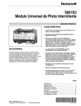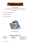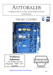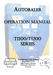
1
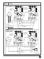
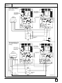
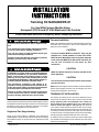
Twinning Kit NAHA003WK.01
For Use With Furnace Models Using
Honeywell ST9120 and ST 9160 Electronic Fan Controls
Please read these instructions completely before attempting installation.
Furnace Installation
!
Electrical shock hazard/Fire and/or explosion hazard.
Turn off electric power supply at disconnect switch
or service panel before starting installation.
Turn off gas supply at field installed manual gas
valve before starting installation.
Failure to follow this warning can result in property
damage, personal injury and/or death.
!
Installation or repairs made by unqualified persons
can result in hazards to you and others. Installation
MUST conform with local building codes or, in the
absence of local codes, with the National Fuel Gas
Code NFPA 54/ANSI A223.1,1990 or latest edition. In
Canada, National Standard CAN/CGA B149--1.
The information contained in this manual is intended for use by a qualified service technician familiar with proper safety procedures and equipped
with the proper tools and test instruments.
Failure to carefully read and follow all instructions
in this manual can result in furnace malfunction,
property damage, personal injury and/or death.
This twinning kit is intended to permit two identical gas furnaces to
be installed connected to the same duct work. Air conditioning can
be added by using one air conditioning evaporator coil sized for
the total air flow capabilities of the two furnaces.
Single and Two Stage Heating
Single or two stage heating is obtainable using twinning kit
NAHA003WK01. Follow the instructions located in the Twinning
Kit Installation section for proper hookup of desired thermostat
staging.
Printed in U.S.A.
Refer to the Installation Instructions packed with the furnaces for
information about clearances, start--up and maintenance, gas
piping and vent installation.
CAUTION
Furnaces installed MUST be identical. They may be
installed on a raised platform or wood floor which
MUST be level. When side return is required, separate
return air drops MUST be made to both furnaces. Do
not use rear of furnace for the return air duct
connection.
CAUTION
Make sure blower motors are wired to operate on the
same speed tap.
CAUTION
Two furnaces must be plumbed with a single supply
gas shut off valve.
NOTE: When twinning kit has been installed, locate the adhesive
backed wiring diagram included in the kit and apply next to the
existing wiring diagrams in the furnaces.
TWINNING KIT INSTALLATION
The twinning kit contains (2) 36” wires of two different colors to
interconnect the electronic fan controls of the two furnaces. For
proper operation, and to avoid damage to the controls, be
sure to match Z1 to Z1 and Z2 to Z2 or C to C and H to H on
each fan control (see Figure 1 and Figure 2). The wires are
color coded to assist with this connection. Each wire is factory
terminated with a special crimped edge connector which will push
into mating connection positions on the edge of the circuit board
on each fan control. The length of these wires can be extended by
cutting and splicing sufficient additional wire to each lead.
An isolation relay is provided to protect the system’s thermostat
from possible overloading due to the combined valve and control
load of the two appliances.
441 06 1003 02 (10/2001)
Installation Procedures
1.
Remove line power from both appliances before starting
installation of the twinning kit.
2.
Locate the Z1 and Z2 or C to C and H to H connections
along one edge of each control (see Figure 1 and
Figure 2). The designations are printed on top of the circuit
board, and a black bar shows the correct orientation of the
metal body which will be pushed in to make connection.
3.
4.
5.
6.
Remove furnace casing hole plugs and route the twinning
leads through bushings provided as required, and lengthen
if necessary by splicing. Be sure to observe the polarity
required so as to match Z1 to Z1 and Z2 to Z2 or C to C and
H to H (see Figure 3).
2.
Connect wire from “W1” of the thermostat to the “W”
connection of the electronic fan control of furnace #1.
3.
Connect wire from “W2” of the thermostat to one side of the
24Vac coil of the isolation relay (terminal #3). (Wire
terminals for connection to the isolation relay are provided
in the kit)
4.
Connect wire from “R” connection at the thermostat to the
“R” connection of the electronic fan control of furnace #1.
5.
Push the terminal into the slot on the circuit board edge. Be
sure to align the body with the black bar to line up the solder
finger below the circuit board (see Figure 1). The terminal
will “bite into” the solder and make the necessary
connection. Repeat for each end of both wires.
Connect wire from the “C” connection of the electronic fan
control of furnace #1 to the other side of the 24Vac coil of the
isolation relay (terminal #1).
6.
Locate and mount the isolation relay in the circulating
blower compartment on the same panel as the electronic
fan control in furnace #1 (see Figure 1 and Figure 2).
Connect one wire to each of the normally open terminals of
the isolation relay (terminal #2 and #4) and connect to the
“R” and “W” connections at the electronic fan control of
furnace #2.
7.
Set the heat delay off timings on each control to the same
setting.
Refer to single stage or two stage thermostat wiring as
noted below.
8.
Set thermostat anticipator setting at 0.75 for the 1st stage
and 0.15 for the 2nd stage.
9.
Recheck wiring connections, splices, and insulation.
Re--apply line power to both appliances.
Single Stage Thermostat Operation
Reference Figure 6 and Figure 7
1.
“G” and “Y” connections only. Interconnect the wiring from
the “C” connections at the terminal blocks on each fan
control. Note: The “Y” connection is not required if air
conditioning is not available.
Interconnect the thermostat wiring in parallel from the
thermostat to the terminal blocks on each fan control, for the
“G” and “Y” connections only. Interconnect the wiring from
the “C” connections at the terminal blocks on each fan
control. Note: The “Y” connection is not required if air
conditioning is not available.
Twinning Kit Operation
1.
Turn the heat/cool switching at the thermostat to “OFF”, or
set so neither a call for heating nor cooling is being made.
2.
Turn the fan switch to “ON” from “AUTO”, or jumper from “R”
to “G” at “furnace 1”. Within several seconds, the circulation
blowers of each furnace will start at the same speed
connected to their respective “heat” speed taps.
3.
Turn the fan switch to “OFF” from “AUTO” or remove the
jumper from “R” to “G”. Both circulation blowers will stop
after several seconds.
4.
Connect wire from the “C” connection of the electronic fan
control of furnace #1 to the other side of the 24Vac coil of the
isolation relay (terminal #1).
Disconnect one wire from the high limit connection on
“furnace 1”. Within several seconds, the circulation blowers
of each furnace will start at the same speed connected to
their respective “heat” speed taps.
5.
Connect one wire to each of the normally open terminals of
the isolation relay (terminals #2 and #4) and connect to the
“R” and “W” connections at the electronic fan control of
furnace #2.
Re--connect the wire removed from the high limit
connection on “furnace 1”. After the completion of the
heating “blower off” delay, both blowers will stop.
6.
Repeat steps (4) and (5) with the limit connection in
“furnace 2” versus :furnace 1². The same operation should
result.
7.
Set the heat delay off timings on each control to the same
setting.
7.
8.
Set thermostat anticipator setting at 0.90.
Operate the system through a normal call for heat, burner
on operation, and burner off operation. Each furnace
should fire and cycle both blowers, including blower on and
off delays, as in a normal single system.
9.
Recheck wiring connections, splices, and insulation.
Re--apply line power to both appliances.
8.
Operate the system through a normal call for cooling. The
compressor operation should function normally, with each
furnace circulation blower operating at the speeds
connected to their respective “cool” speed taps after
cooling “blower on” delay. When the call for cooling ends,
the circulation blowers will stop upon the completion of the
“cooling off” delay.
2.
Connect wire from “W” connection at the thermostat to the
“W” connection of the electronic fan control of furnace #1.
3.
Connect wire from “R” connection at the thermostat to the
“R” connection of the electronic fan control of furnace #1.
4.
Connect wire from the “W” connection of the electronic fan
control of furnace #1 to one side of the 24Vac coil of the
isolation relay (terminal #3). (Wire terminals for connection
to the isolation relay are provided in the kit)
5.
6.
Two Stage Thermostat Operation
Reference Figure 6 and Figure 7
1.
2
Interconnect the thermostat wiring in parallel from the
thermostat to the terminal blocks on each fan control, for the
441 06 1003 02 (10/2001)
Figure 1
Connection of Twinning Leads and Locating Isolation Relay On Furnace #1 Control Panel
CONTROL PANEL (Located In Blower Compartment).
Z1
T
Transformer
W
I
N
ST9120C40
ELECTRONIC
FAN CONTROL
Twinning Leads
ST9120
ISOLATION RELAY
4
(SPST)
2
DRILL TWO 1/8” Dia.
1
3
CONTROL PANEL (Located In Blower Compartment).
H
ELECTRONIC
DATA
FAN CONTROL
ST9160
C
TWIN
ST9160B
Transformer
Twinning Leads
ISOLATION RELAY
4
(SPST)
2
1
DRILL TWO 1/8” Dia.
3
25--23--77
3
Figure 2
CONTROLS FOR ST 9210 & ST9160
ELECTRONIC FAN CONTROL
(ST9120)
ELECTRONIC FAN CONTROL
(ST9120)
Z1
T
W
I
N
Twinning Leads
Connect Z1 To Z1
And Z2 To Z2.
ELECTRONIC FAN CONTROL
(ST9160)
ST9160B
H
C
ST9160B
TWIN
ELECTRONIC FAN CONTROL
(ST9160)
DATA
DATA
Twining Leads
Connect H To H
And C To C.
4
25--23--78
441 06 1003 02 (10/2001)
Figure 3
Proper Connection of Twinning Leads for ST 9120 & ST 9160
FURNACE #2
FURNACE #1
Splice if Required,to
obtain necessary length.
Bushings
ST9120
ST9120
Z2 TO Z2
ST9120C40
Twinning
Leads
ST9120C40
Z1 TO Z1
4
2
1
3
FURNACE #2
FURNACE #1
Splice if Required,to
obtain necessary length.
Bushings
ST9160
ST9160
H TO H
Twinning
Leads
C TO C
4
2
1
3
25--23--79
5
Figure 4
6
Proper Connection of Twinning Leads for ST 9120
441 06 1003 02 (10/2001)
Figure 5
Proper Connection of Twinning Leads for ST 9160
Thermostat Wiring For
Single Stage Heating
ELECTRONIC
FAN CONTROL
FURNACE #1
ELECTRONIC
FAN CONTROL
FURNACE #2
WALL
Connect H to H
Connect C to C
THERMOSTAT
R
C
W
C
W
Y
H
TWIN
R
C
H
G
Y
5
5
TWIN
W R
C
G
G
4
2
1
3
ISOLATION
RELAY
Thermostat Wiring For
Two Stage Heating
ELECTRONIC
FAN CONTROL
FURNACE #1
ELECTRONIC
FAN CONTROL
FURNACE #2
WALL
Connect H to H
Connect C to C
THERMOSTAT
R
C
W Y
C
W Y
H
TWIN
R
C
H
C
G
5
5
TWIN
G W2 W1 R
G
ISOLATION
RELAY
4
2
1
3
25--23--80
7
Figure 6
ST 9120
Thermostat Wiring For
Single Stage Heating
And Two Stage Cooling
ELECTRONIC
FAN CONTROL
FURNACE #1
WALL
Connect Z1 To Z1
THERMOSTAT
Connect Z2 To Z2
G Y2 Y1 W1 R
4
Y
C
ELECTRONIC
FAN CONTROL
FURNACE #2
2
A/C
CONDENSERS
1
Y
3
ISOLATION
RELAY
C
Thermostat Wiring For
Two Stage Heating And
Single Stage Cooling
ELECTRONIC
FAN CONTROL
FURNACE #1
Connect Z1 To Z1
WALL
THERMOSTAT
Connect Z2 To Z2
G Y W2 W1 R
ELECTRONIC
FAN CONTROL
FURNACE #2
4
2
1
8
3
ISOLATION
RELAY
A/C
CONDENSER
C
Y
25--23--82
441 06 1003 02 (10/2001)
Figure 7
ST 9160
Thermostat Wiring For
Single Stage Heating
And Two Stage Cooling
ELECTRONIC
FAN CONTROL
FURNACE #2
ELECTRONIC
FAN CONTROL
FURNACE #1
WALL
Connect H to H
Connect C to C
THERMOSTAT
W
C
H
TWIN
5
C
R
W
G
Y
4
Y
C
C
H
G
Y
5
R
C
TWIN
G Y2 Y1 W1 R
2
A/C
CONDENSERS
1
Y
ISOLATION
RELAY
3
C
Thermostat Wiring For
Two Stage Heating And
Single Stage Cooling
ELECTRONIC
FAN CONTROL
FURNACE #2
ELECTRONIC
FAN CONTROL
FURNACE #1
WALL
Connect H to H
Connect C to C
THERMOSTAT
R
C
W Y
C
H
TWIN
R
C
H
C
G
5
5
TWIN
G Y W2 W1 R
G
W Y
4
2
1
3
ISOLATION
RELAY
A/C
CONDENSER
C
Y
25--23--81
9
Figure 8
Thermostat Wiring For
Single Stage Heating
And Cooling.
ELECTRONIC
FAN CONTROL
FURNACE #1
Connect Z1 To Z1
WALL
THERMOSTAT
G Y
Connect Z2 To Z2
W R
ELECTRONIC
FAN CONTROL
FURNACE #2
4
2
3
1
ISOLATION
RELAY
A/C
CONDENSER
C
Y
Thermostat Wiring For
Two Stage Heating &
Cooling
ELECTRONIC
FAN CONTROL
FURNACE #1
WALL
Connect Z1 To Z1
THERMOSTAT
Connect Z2 To Z2
G Y2 Y1 W2 W1 R
4
Y
C
Y
C
10
ELECTRONIC
FAN CONTROL
FURNACE #2
2
A/C
CONDENSERS
1
3
ISOLATION
RELAY
25--23--83
441 06 1003 02 (10/2001)
Figure 9
Thermostat Wiring For
Single Stage Heating
And Cooling
ELECTRONIC
FAN CONTROL
FURNACE #2
ELECTRONIC
FAN CONTROL
FURNACE #1
WALL
Connect H to H
Connect C to C
THERMOSTAT
W
C
R
W
Y
H
G
5
C
C
TWIN
G
Y
5
R
H
W R
TWIN
Y
C
G
4
2
1
ISOLATION
RELAY
3
Y
A/C
CONDENSERS
C
Thermostat Wiring For
Two Stage Heating &
Cooling
ELECTRONIC
FAN CONTROL
FURNACE #2
ELECTRONIC
FAN CONTROL
FURNACE #1
WALL
Connect H to H
Connect C to C
THERMOSTAT
R
C
W Y
C
W Y
H
TWIN
R
C
H
C
G
5
5
TWIN
G Y2 Y1 W2 W1 R
G
Y
4
C
2
Y
C
A/C
CONDENSER s
1
3
ISOLATION
RELAY
25--23--81a
11