1
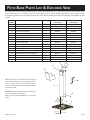
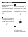
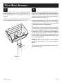
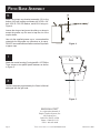
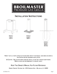
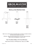
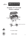
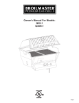
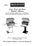
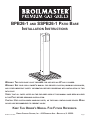
BPB26-1 AND SSPB26-1 PATIO BASE
INSTALLATION INSTRUCTIONS
WARNING: THIS PATIO BASE IS NOT DESIGNED FOR USE WITH AN LP GAS CYLINDER.
WARNING: SEE YOUR GRILL OWNER'S MANUAL FOR PROPER LOCATION, MINIMUM CLEARANCES,
AND OTHER IMPORTANT SAFETY INFORMATION BEFORE PROCEEDING WITH INSTALLATION OF THIS
PATIO POST.
VERIFY THAT ALL PARTS LISTED ON THE EXPLODED VIEW OF THIS MANUAL HAVE BEEN INCLUDED
IN THIS POST BEFORE BEGINNING INSTALLATION.
CAUTION: USE CAUTION WHEN HANDLING PARTS, AS THEY MAY CONTAIN SHARP EDGES. WORK
GLOVES ARE RECOMMENDED TO PREVENT INJURY.
KEEP THIS OWNER'S MANUAL FOR FUTURE REFERENCE.
B101075-0-1006
EMPIRE COMFORT SYSTEMS, INC. • 918 FREEBURG AVE. • BELLEVILLE, IL 62220
Page 1
THIS GAS ACCESSORY IS DESIGNED FOR OUTDOOR USE ONLY:
IMPORTANT
THIS
MANUAL SHOULD BE READ THOROUGHLY BY THE PERSON INSTALLING THE GRILL MOUNTING AND ALL
PERSONS WHO WILL USE AND MAINTAIN THE GRILL MOUNTING.
IS LEFT IN THE POSSESSION OF THE USER.
THE INSTALLER SHOULD BE SURE THE MANUAL
THE USER SHOULD RETAIN THIS MANUAL FOR FUTURE REFERENCE
WHEN USING OR CLEANING THE GRILL MOUNTING AND TO PROPERLY IDENTIFY ANY REPAIR PARTS THAT MAY BE
REQUIRED.
WARNING
REFERENCE THIS MANUAL FOR PROPER INSTALLATION AND MAINTENANCE INSTRUCTIONS. IMPROPER INSTALLATION, ADJUSTMENT, ALTERATION, SERVICE OR MAINTENANCE CAN CAUSE PERSONAL INJURY OR PROPERTY
DAMAGE. FOR ASSISTANCE OR ADDITIONAL INFORMATION CONSULT A QUALIFIED INSTALLER, SERVICE AGENCY
OR THE GAS SUPPLIER.
CAUTION:
THE GRILL AND ITS INDIVIDUAL SHUTOFF VALVE MUST BE DISCONNECTED FROM THE GAS SUPPLY PIPING SYSTEM
DURING ANY PRESSURE TESTING OF THAT SYSTEM AT TEST PRESSURES IN EXCESS OF 1/2 PSIG.
CAUTION:
THE
GRILL MUST BE ISOLATED FROM THE GAS SUPPLY PIPING SYSTEM BY CLOSING ITS INDIVIDUAL MANUAL
SHUTOFF VALVE DURING ANY PRESSURE TESTING OF THE GAS SUPPLY PIPING SYSTEM AT TEST PRESSURES
EQUAL TO OR LESS THAN
1/2 PSIG.
CAUTION:
PARTS MAY HAVE SHARP EDGES. WEAR LEATHER WORK GLOVES AND HANDLE PARTS CAREFULLY DURING THE
UNPACKING, ASSEMBLY AND THE INSTALLATION.
WARNING
DO NOT SUPPLY LP GAS TO A GRILL DESIGNED FOR NATURAL GAS NOR NATURAL GAS TO A GRILL DESIGNED
FOR LP GAS.
NOTICE
ASSEMBLE PATIO BASE BEFORE ASSEMBLING GRILL.
Page 2
B101075-0-1006
TABLE OF CONTENTS
CONGRATULATIONS!
You have chosen the finest grill for your outdoor cooking pleasure. Please take time to read this entire manual
before assembling your premium Broilmaster® accessory.
Important Information........................................................................................................................................ 4
Patio Base Parts List & Exploded View ............................................................................................................ 5
Patio Base Assembly ....................................................................................................................................... 6-8
B101075-0-1006
Page 3
IMPORTANT INFORMATION
Grill Location
Broilmaster Premium Gas Grills are designed for outdoor use ONLY.
These mounting accessories are designed for use with
Broilmaster gas grills and must not be used with any
other grill or for any other purpose.
Never install or operate your grill in any building, garage,
or other enclosed area.
For your safety, the grill should not be installed or operated under any combustible materials, such as carports,
covered porches, awnings, or overhangs.
Never install or use your grill in or on any recreational
vehicle or boat.
CAUTION: THE INSTALLATION AND OPERATION OF THIS GRILL AT
CLEARANCES LESS THAN SPECIFIED BELOW MAY LEAD TO THE POSSIBILITY OF FIRE, PROPERTY DAMAGE, OR PERSONAL INJURY.
A minimum clearance of sixteen (16") inches is required
from all sides of the grill to any combustible material.
A minimum clearance of eighteen (18") inches is required from the back of the grill to any combustible
material.
Examples of combustible materials are patio furniture,
fences, or the wall of your home.
The area surrounding the grill should be clear to ensure
proper ventilation. Do not obstruct the flow of combustion and ventilation air in any way. The ventilation
openings on the propane cylinder enclosure must also
remain free and clear of debris.
WARNING: DO
Gas Types
Never use liquid propane gas with a grill designed for
natural gas, or natural gas with a grill designed for liquid
propane gas. The type of gas required for your grill is
defined on its product identification label. Questions
regarding different types of gases should be directed
to your gas supplier.
Cleaning
The exterior of your post may be cleaned with hot water
and mild detergent as needed.
Touch-up paint is available through your Broilmaster
dealer.
Stainless steel surfaces may be cleaned with a sprayon stainless steel cleaner available at most hardware
stores.
Important: Do not use harsh or abrasive cleaners! Your
post has a highly polished surface and may be easily
scratched.
PERIODIC INSPECTION
AND
MAINTE-
NANCE
Periodic inspections and maintenance are essential. All
Broilmaster Gas Grill products or mechanical devices
eventually begin to wear due to environment, contaminants, corrosion or aging. Inspect all components at
least twice per year and replace any that show wear.
If any parts are damaged or missing, you may order
parts from your local Broilmaster dealer. Please refer to
the Parts Diagram and Parts List section of this manual
for more detailed information.
NOT INSTALL OR OPERATE A GAS GRILL
WHERE GASOLINE OR OTHER FLAMMABLE MATERIALS ARE USED
OR STORED.
FAILURE
TO COMPLY WITH THIS WARNING COULD
RESULT IN EXPLOSION OR FIRE CAUSING PROPERTY DAMAGE OR
PERSONAL INJURY.
Page 4
B101075-0-1006
PATIO BASE PARTS LIST & EXPLODED VIEW
All repair part orders should be placed through your local Broilmaster dealer. To locate a dealer in your area, contact Broilmaster Customer Service at 800-851-3153 • www.broilmaster.com To ensure prompt and accurate service, please provide
the following information when placing a repair part order: Model Number, Part Name, Part Number, and Quantity of parts
needed.
Key
Number
Part Name
Quantity
BPB26
Part Number
SSPB26
Part Number
1
9/32 I.D. x 5/8 O.D. Flat Washer
13
B100136
B100136
2
1/4 Lock Washer
16
B100139
B100139
3
1/4-20 Hex Nut
16
B100120
B100120
4
1/4-20 x 1 3/4" Eyebolt
4
B100118
B100118
5
1/4-20 x 3/4" Bolt
8
B100115
B063096
6
Control Housing
1
B101076
B101060
7
26" Square Post
1
B878517
B070283
8
1/4-20 x 4" Eyebolt
4
B100111
B100111
9
Cast Iron Patio Base
1
B074604
B074604
10
Grease Cup Bracket Assembly
1
B100545
B100545
NS
#10-24 Wing Nut
2
B100125
B100125
NS
#8 x 1/2" Phillips Truss Screw
2
B100132
N/A
NS
Fastener Panel - Plastic
2
N/A
B068182
NS
Stainless Steel Flex Tube Assembly
1
B076518
B076518
NS
Male Flare Fitting
1
B100100
B100100
NS
#10-24 x 3/4" Bolt
1
B100128
B100128
NS
Grease Cup
1
B100526
B100526
4
5
12
3
6
REMOVE
10
PROTECTIVE COATING FROM STAINLESS
STEEL PARTS STARTING AT POP RIVETS AND VERIFY
THAT ALL PARTS LISTED IN THE EXPLODED VIEW ON
THIS PAGE HAVE BEEN INCLUDED BEFORE BEGINNING
THIS INSTALLATION.
7
CAUTION: USE CAUTION WHEN HANDLING PARTS, AS
5
THEY MAY CONTAIN SHARP EDGES.
WORK
INJURY.
GLOVES ARE RECOMMENDED TO PREVENT
8
3 2
1
1
B101075-0-1006
3
9
2
Page 5
PATIO BASE ASSEMBLY
The BPB26 and SSPB26 Patio Base are only for use
with Broilmaster Gas Grills. Before proceeding with
installation read the Owner’s Manual for the proper location and minimum clearances to combustible materials
for your grill and patio base.
Verify that all parts listed in the exploded view of this
product have been included before beginning this installation.
Recommended Tools:
• Two adjustable wrenches or a socket set
• A medium Phillips screwdriver
• Pipe thread sealer or Teflon tape (for gas connections)
• Soapy water solution (to test for leaks)
2
Fasten the bottom of the post to the cast iron patio
base (9) using 9/32 ID x 5/8 OD flat washers, 1/4 lock
washers, and 1/4-20 hex nuts. FIGURE 2.
Anchor the cast iron patio base to your patio using
the two holes provided in the base. (Hardware not
included)
Note: Make sure that the large rectangular cut out is
facing in the direction that you want your grill to face.
FIGURE 2.
1
Attach four 1/4-20 x 4" eyebolts (8) to the bottom of the
26" square post (7) using 1/4 - 20 x 3/4" bolts (5), 9/32
ID x 5/8 OD flat washers (1), 1/4 lock washers (2), and
1/4-20 hex nuts (3). Figure 1.
NOTE: The large rectangular cut out is located at the
front of the post near the top.
Figure 2
3
Insert the stainless steel flex tube assembly into the
post.
The inlet side of the gas tubing may protrude from the
bottom of the patio base or through the large circular
hole in the back of the square post.
Note: Do not attempt to cut or alter the flex tube in any
way.
Figure 1
Page 6
B101075-0-1006
PATIO BASE ASSEMBLY
4
5
Fasten the four 1/4-20 x 1 3/4" eyebolts (4) to the top
of the square post using 1/4 - 20 x 3/4" bolts, 9/32 ID
x 5/8 OD flat washers, 1/4 lock washers, and 1/4-20
hex nuts.
Position the grill head onto the eyebolts and fasten with
1/4 lock washers and 1/4-20 Hex nuts. FIGURE 3.
Arrange with your local gas company or licensed contractor to have a gas supply line connected to the inlet
of the stainless steel flex tube assembly. The gas supply
must have a shutoff valve inside the wall and must be
shutoff when the grill is not in use.
Use pipe thread sealant or Teflon tape at the threads
of each connection being careful to not allow any of
these materials into the flare seat. Test for gas leaks
as directed by the grill’s Owners Manual.
The grill and its individual shutoff valves must be disconnected from the gas supply piping system during
any pressure testing of that system at test pressures
in excess of 1/2 PSIG.The grill must be isolated from
the gas supply piping system by closing its individual
manual shutoff valves during any pressure testing of
the gas supply piping system at test pressures equal
to or less than 1/2 PSIG.
WARNING: DO
NOT SUPPLY
LP
GAS TO A GRILL DESIGNED
FOR NATURAL GAS OR NATURAL GAS TO A GRILL DESIGNED FOR
LP GAS.
Gas leak tests should be completed as directed in the
grill owner's manual.
Figure 3
B101075-0-1006
Page 7
PATIO BASE ASSEMBLY
6
Attach the grease cup bracket assembly (10) to the
bottom of the grill casting and fasten with 10-24 x 3/4"
bolt, 9/32 ID x 5/8 OD washer, and #10-24 wing nut.
Figure 4.
Loosen the wing nut and move the slide up or down to
accept the grease cup. Be sure to trap the rim of the
cup as shown.
Use only the supplied grease cup or noncombustible
containers for the grease cup (aluminum or tin cans).
DO NOT use combustible containers such as Styrofoam
or paper cups.
Figure 4
7
Attach the control housing (6) using two #8 x 1/2" Phillips
Truss screws or two plastic panel fasteners as shown
in Figure 5.
8
Continue assembly as directed by the Owner’s Manual
packaged with the grill head.
Figure 5
BROILMASTER®
is a registered trademark of
Empire Comfort Systems, Inc.
918 Freeburg Ave.
Belleville, Illinois 62220
Phone: 1-800-851-3153
FAX: 1-800-443-8648
Page 8
VISIT OUR WEB SITE AT WWW.broilmaster.com
B101075-0-1006