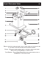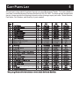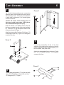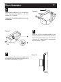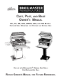
1
CART, POST, AND BASE
OWNER’S MANUAL
DC, PC, PB, U26, U26SS, U48,
OUTDOOR GRILL MOUNTINGS
FOR
FOR
AND
PROPANE
P48 MODELS
AND
NATURAL GAS
BROILMASTER® PREMIUM GAS GRILLS
FOR OUTDOOR USE ONLY
USE WITH
RETAIN OWNER’S MANUAL FOR FUTURE REFERENCE.
THIS GAS ACCESSORY IS DESIGNED FOR OUTDOOR USE ONLY
IMPORTANT
THIS MANUAL SHOULD BE READ THOROUGHLY BY THE PERSON INSTALLING THE GRILL MOUNTING AND ALL
PERSONS WHO WILL USE AND MAINTAIN THE GRILL MOUNTING. THE INSTALLER SHOULD BE SURE THE
MANUAL IS LEFT IN THE POSSESSION OF THE USER. THE USER SHOULD RETAIN THIS MANUAL FOR FUTURE
REFERENCE WHEN USING OR CLEANING THE GRILL MOUNTING AND TO PROPERLY IDENTIFY ANY REPAIR
PARTS THAT MAY BE REQUIRED.
WARNING
REFERENCE
THIS MANUAL FOR PROPER INSTALLATION AND MAINTENANCE INSTRUCTIONS.
IMPROPER
INSTALLATION, ADJUSTMENT, ALTERATION, SERVICE OR MAINTENANCE CAN CAUSE PERSONAL INJURY OR
PROPERTY DAMAGE.
FOR ASSISTANCE OR ADDITIONAL INFORMATION CONSULT A QUALIFIED INSTALLER,
SERVICE AGENCY OR THE GAS SUPPLIER.
CAUTION:
THE GRILL AND ITS INDIVIDUAL SHUTOFF VALVE MUST BE DISCONNECTED FROM THE GAS SUPPLY PIPING
SYSTEM DURING ANY PRESSURE TESTING OF THAT SYSTEM AT TEST PRESSURES IN EXCESS OF 1/2 PSIG.
CAUTION:
THE
GRILL MUST BE ISOLATED FROM THE GAS SUPPLY PIPING SYSTEM BY CLOSING ITS INDIVIDUAL
MANUAL SHUTOFF VALVE DURING ANY PRESSURE TESTING OF THE GAS SUPPLY PIPING SYSTEM AT TEST
PRESSURES EQUAL TO OR LESS THAN
1/2 PSIG.
CAUTION:
PARTS
MAY HAVE SHARP EDGES.
WEAR
LEATHER WORK GLOVES AND HANDLE PARTS CAREFULLY
DURING THE UNPACKING, ASSEMBLY AND THE INSTALLATION.
WARNING
DO
LP GAS
DESIGNED FOR LP GAS.
NOT SUPPLY
TO A GRILL DESIGNED FOR NATURAL GAS NOR NATURAL GAS TO A GRILL
TABLE OF CONTENTS
1
CONGRATULATIONS!
You have chosen the finest grill for your outdoor cooking pleasure. Please take time to read
this entire manual before assembling your premium Broilmaster® accessory.
C22
Important Information............................................................................................................2
Cart and Patio Base (DC, PC and PB Models)............................................................3-8
Patio Post (U26 and U26SS Models) .........................................................................9-13
In-Ground Post (U48 and P48 Models).... ................................. .. ................................14-18
Warranty ............................................................................... ............ ..................20-21
Your Broilmaster® accessory is identified by model number, serial number, and gas
type. This information is provided on a product identification label located on the
accessory. The grill’s model number, serial number, and gas type must also be provided
when contacting your Broilmaster® dealer. For your convenience, complete this section
for future reference when contacting your dealer.
Grill Information
Model No.
Dealer
Serial No.
Dealer Phone No.
Gas Type: Propane
Natural
Date of Purchase
IMPORTANT I NFORMATION
2
Grill Location
Gas Types
Broilmaster® Premium Gas Grills are designed
for outdoor use ONLY.
Never use liquid propane gas with a grill
designed for natural gas, or natural gas with a
grill designed for liquid propane gas. The type
of gas required for your grill is defined on its
product identification label. Questions
regarding different types of gases should be
directed to your gas supplier.
These mounting accessories are designed for
use with Broilmaster® gas grills and must not
be used with any other grill or for any other
purpose.
Never install or operate your grill in any building,
garage, or other enclosed area.
For your safety, the grill should not be installed
or operated under any combustible materials,
such as carports, covered porches, awnings,
or overhangs.
Never install or use your grill in or on any
recreational vehicle or boat.
CAUTION: THE INSTALLATION AND OPERATION OF
THIS GRILL AT CLEARANCES LESS THAN SPECIFIED
BELOW MAY LEAD TO THE POSSIBILITY OF FIRE ,
PROPERTY DAMAGE, OR PERSONAL INJURY.
A minimum clearance of sixteen (16”) inches is
required from all sides of the grill to any
combustible material.
A minimum clearance of eighteen (18”) inches is
required from the back of the grill to any combustible
material.
Examples of combustible materials are patio
furniture, fences, or the wall of your home.
The area surrounding the grill should be clear
to ensure proper ventilation. Do not obstruct
the flow of combustion and ventilation air in any
way. The ventilation openings on the propane
cylinder enclosure must also remain free and
clear of debris.
WARNING: DO NOT INSTALL OR OPERATE A GAS
GRILL WHERE GASOLINE OR OTHER FLAMMABLE
MATERIALS ARE USED OR STORED. FAILURE TO COMPLY
WITH THIS WARNING COULD RESULT IN EXPLOSION OR
FIRE CAUSING PROPERTY DAMAGE OR PERSONAL INJURY.
Cleaning
The exterior of your cart or post may be cleaned
with hot water and mild detergent as needed.
Touch-up paint is available through your
Broilmaster® dealer.
Stainless steel surfaces may be cleaned with a
spray-on stainless steel cleaner available at most
hardware stores.
Important: Do not use harsh or abrasive
cleaners! Your cart or post has a highly polished
surface and may be easily scratched.
P ERIODIC I NSPECTION
M AINTENANCE
AND
Periodic inspections and maintenance are
essential. All Broilmaster® Gas Grill products or
mechanical devices eventually begin to wear
due to environment, contaminants, corrosion or
aging. Inspect all components at least twice per
year and replace any that show wear.
If any parts are damaged or missing, you may
order parts from your local Broilmaster® dealer.
Please refer to the Parts Diagram and Parts List
section of this manual for more detailed
information.
PC, DC CART AND PB BASE
INSTALLATION INSTRUCTIONS
VERIFY
THAT ALL PARTS LISTED ON THE EXPLODED VIEW OF THIS MANUAL HAVE BEEN
INCLUDED IN THIS
CAUTION: USE
CART
BEFORE BEGINNING INSTALLATION.
CAUTION WHEN HANDLING PARTS, AS THEY MAY CONTAIN SHARP EDGES.
WORK
GLOVES ARE RECOMMENDED TO PREVENT INJURY.
KEEP THIS OWNER’S MANUAL FOR FUTURE REFERENCE.
EMPIRE COMFORT SYSTEMS, INC • 918 FREEBURG AVE. • BELLEVILLE, IL 62220 • 618-233-7420
4
CART EXPLODED VIEW
1
13
2
14
3
15
16
4
17
5
18
6
19
7
20
8
9
21
10
22
11
23
12
24
REMOVE
PROTECTIVE COATING AND VERIFY THAT ALL PARTS LISTED ON THE EXPLODED VIEW
OF THIS MANUAL HAVE BEEN INCLUDED BEFORE BEGINNING ASSEMBLY.
CAUTION: USE
CAUTION WHEN HANDLING PARTS, AS THEY MAY CONTAIN SHARP EDGES.
WORK
GLOVES ARE RECOMMENDED TO PREVENT INJURY.
TOOLS REQUIRED: PHILLIPS SCREW DRIVER (AN
ELECTRIC SCREW DRIVER OR DRILL IS
RECOMMENDED TO EASE INSTALLATION.)
CART PARTS LIST
5
All repair part orders should be placed through your local Broilmaster® dealer. To locate a dealer in
your area, contact Broilmaster Customer Service at (618) 233-7420. To ensure prompt and accurate
service, please provide the following information when placing a repair part order: Model Number,
Part Name, Part Number, and Quantity of parts needed.
Key
No.
1
2
3
4
5
6
7
8
9
10
11
12
13
14
15
16
17
18
19
20
21
22
23
24
Part Name
Drip Pan Drawer
Wing Nut
Left Assembly
Cylinder Retainer
Control Housing
Front Assembly
Base Assembly
Caster with out Brake
Caster Pad
Caster with Brake
Hub Cap
Hub Cap Cover
Drip Pan
10-24x3/8 Phillips Truss Screw
1/4-20x3/4 Phillips Truss Screw
Rear Brace
Drip Pan Bracket
Right Assembly
10-32x1/2 Phillips Screw
Base Channel
Tie Down Plate
Axle
8" Wheel
Burner Stabilizer Kit*
Qty.
1
3
1
1
1
1
1
1
2
1
2
2
2
2
17
1
1
1
6
2
1
1
2
1
PC
Part No.
072206
063097
076782
064791
072221
072178
072163
063103
072232
063104
9130020
063106
060337
HD388
072217
072201
072215
076783
076537
072212
N/A
063107
063105
906236
DC
Part No.
072211
072181
076785
064791
072222
072191
072187
063103
072234
063104
9130020
073271
060337
HD577
072220
072203
072215
076787
076537
072213
N/A
063107
073272
906236
*See your grill manual for instructions on how to install the Burner Stabilizer.
PB
Part No.
072206
063097
076782
064791
072221
072178
072164
N/A
N/A
N/A
N/A
N/A
060337
HD388
072217
072201
072215
076783
076537
072212
070492
N/A
N/A
906236
6
CART ASSEMBLY
1
FIGURE 1
Tip: To aid in the assembly process , you may be
asked to leave certain screws loose until later in
the assembly process. Please pay close attention
to each step to determine if you should tighten
screws at that time.
1/8"
Caution: Be careful when handling parts, as
they may contain sharp edges. Work gloves
are recommended to prevent injury.
19
Insert six #10-32 x 1/2 phillips screws (19) into
the factory installed clip nuts on the front assembly
(6). Leave an 1/8" gap beneath the head of the
screws as shown by Figure 1.
3
6
Attach front assembly (6) to base (7) with two ˘-20
x 3/4 phillips screws (15). Figure 2. Do not tighten
screws at this time.
FIGURE 2
2
6
15
Fasten side assemblies (3,18) to the front
assembly (6) by aligning the keyholes on the side
panels to the three screws installed by Step 1, on
the front panel, then push down.
Attach the side assemblies to the base (7) with
two ˘-20 x 3/4 phillips screws. Do not tighten
screws at this time.
7
FIGURE 3
3
Attach drip pan bracket (17) to the cart with
two ˘-20 x 3/4 phillips screws (15) and two ˘20 Wing Nuts (2). Figure 3.
2
17
16
15
7
CART ASSEMBLY
4
15
Attach the Rear Brace (16) to the Left and
Right Side Assemblies with four ˘-20 x 3/4
screws (15). Figure 4.
FIGURE 4
16
Important: Completely tighten all screws
at this time.
5
FIGURE 5
2
Install one 1/4-20 x 3/4 phillips screw (15) into
the factory installed nut on the Left Side Assembly.
Fasten the Cylinder Retainer (4) to the screw with
a wing nut (2). Adjust height to accommodate
your LP cylinder. Figure 5.
4
15
6
Slide the flanges of the Control Housing (5) behind
the opening. Allow the Control Housing to rest at
the bottom of the opening. Figure 6.
FIGURE 6
8
CART ASSEMBLY
7
Using four ˘-20 x 3/4 screws (15), fasten the
grill to the cart. Figure 7.
FIGURE 7
15
Note: To ease assembly you may wish to install
the igniter as shown in your Broilmaster® grill
manual before attaching the grill to the cart.
8
FIGURE 8
13
1
5
14
17
Align the holes in the front with the nuts on the
control housing (5) (with flanges positioned inside
cart) and fasten with two 10-24 x 3/8 phillips head
screws (14). Place the drip pan (13) in the drip
pan drawer (1) and slide onto drip pan bracket
(17). Figure 8.
PB Model: Tie down plate (21) provided to anchor
post base to patio or deck. Hardware not included.
U26 AND U26SS PATIO BASE POST
INSTALLATION INSTRUCTIONS
1
2
3
5
4
6
3
2
1
5
7
8
3
2
1
WARNING: THIS IN-GROUND POST IS NOT DESIGNED FOR USE WITH AN LP GAS CYLINDER.
KEEP THIS OWNER’S MANUAL FOR FUTURE REFERENCE.
EMPIRE COMFORT SYSTEMS, INC. • 918 FREEBURG AVE. • BELLEVILLE, IL 62220 • 618-233-7420
10
PATIO BASE POST PART LIST
All repair part orders should be placed through your local Broilmaster® dealer. To locate a dealer in
your area, contact Broilmaster Customer Service at (618) 233-7420. To ensure prompt and accurate
service, please provide the following information when placing a repair part order: Model Number,
Part Name, Part Number, and Quantity of parts needed.
ITEM
NUMBER
PART NUMBER
QTY.
U26 PART
NUMBER
U26SS PART
NUMBER
1
9/32 ID x 5/8 OD FLAT WASHER
16
HD504
HD504
2
1/4 LOCK WASHER
12
HD545
HD545
3
1/4-20 HEX NUT
16
HD197
HD197
4
1/4-20 x 1-3/4" EYEBOLT
4
HD170
HD170
5
1/4-20 x 3/4" BOLT
8
HD125
063096
6
26" SQUARE POST
1
878517P
070283
7
1/4-20 x 4" EYEBOLT
4
HD009
HD009
8
CAST IRON PATIO BASE
1
826468
826468
9
10-24 WING NUT
1
HD242
HD242
10
CONTROL HOUSING
1
896076P
064854
11
#10 SCREW/PANEL FASTENER
2
HD427
068182
12
STAINLESS STEEL FLEX TUBE ASSEMBLY
1
076518
076518
13
GREASE CUP BRACKET ASSEMBLY
1
065821
065821
14
MALE FLARE FITTING
1
248x6x6
248x6x6
PATIO BASE POST ASSEMBLY
The U26 and U26SS Patio Base Posts are only
for use with Broilmaster® Gas Grills. Before
proceeding with installation read the Owner’s
Manual for the proper location and minimum
clearances to combustible materials for your grill
and patio base post.
Verify that all parts listed in the exploded view of
this product have been included before beginning
this installation.
Recommended Tools:
• Two adjustable wrenches or a socket set
• A medium Phillips screwdriver
• Pipe thread sealer or Teflon tape (for gas
connections)
• Soapy water solution (to test for leaks)
11
2
Fasten the bottom of the post to the cast iron patio
base using flat washers (1), lock washers (2), and
nuts (3). FIGURE 2.
Anchor the base to your patio using the two holes
provided in the base. (Hardware not included)
Note: Make sure that the large rectangular cut out
is facing in the direction that you want your grill to
face. FIGURE 2.
FIGURE 2
1
Attach four ˘-20 x 4" eyebolts (7) to the bottom of
the square post using hex head bolts (5), flat
washers (1), lock washers (2), and nuts (3).
Figure 1.
NOTE: The large rectangular cut out is located at
the front of the post near the top.
8
1
FIGURE 1
3
2
3
Insert the flex tubing into the post.
The inlet side of the gas tubing may protrude from
the bottom of the patio base or through the large
circular hole in the back of the square post.
Note: Do not attempt to cut or alter the flex tube in
any way.
3
2
1 7
5
PATIO BASE POST ASSEMBLY
12
THE GRILL MUST BE ISOLATED FROM THE GAS SUPPLY
4
PIPING SYSTEM BY CLOSING ITS INDIVIDUAL MANUAL
Fasten the four ˘-20 x 13/4" short eyebolts (4) to
the top of the square post using hex head bolts
(5), flat washers (1), lock washers (2), and nuts
(3).
SHUTOFF VALVES DURING ANY PRESSURE TESTING OF
THE GAS SUPPLY PIPING SYSTEM AT TEST PRESSURES
EQUAL TO OR LESS THAN
˚ PSIG.
Position the grill head onto the eyebolts and fasten
with lock washers (2) and nuts (3). FIGURE 3.
FIGURE 3
3
2
12
FIGURE 4
4
GRILL
BOTTOM
WARNING: DO
NOT SUPPLY
LP
GAS TO A GRILL
DESIGNED FOR NATURAL GAS OR NATURAL GAS TO A
6
LP GAS.
6
5
Arrange with your local gas company to have a
gas supply line connected to the inlet of the flex
tube. The gas supply must have a shutoff valve
inside the wall and must be shutoff when the grill
is not in use.
Use pipe thread sealant or Teflon tape at the
threads of each connection being careful to not
allow any of these materials into the flare seat.
Test for gas leaks as directed by the grill’s Owner
Manual.
THE GRILL AND ITS INDIVIDUAL SHUTOFF VALVES MUST
BE DISCONNECTED FROM THE GAS SUPPLY PIPING
SYSTEM DURING ANY PRESSURE TESTING OF THAT
SYSTEM AT TEST PRESSURES IN EXCESS OF
GRILL DESIGNED FOR
˚ PSIG.
Attach the retainer bracket to the slide with a wing
nut as shown by Figure 5.
FIGURE 5
13
9
PATIO BASE POST ASSEMBLY
7
13
FIGURE 6
Attach the bracket and slide assembly to the
factory installed screw located in the bottom of the
grill housing. Figure 6.
Loosen the wing nut and move the slide up or
down to accept the grease cup. Be sure to trap the
rim of the cup as shown.
Use only noncombustible containers for the
grease cup (aluminum or tin cans) do not use
combustible containers such as Styrofoam or
paper cups.
FIGURE 7
8
Attach the control housing (10) using two #8 x 1/2
screws (11) or two plastic panel fasteners as
shown in Figure 7.
10
10
11
11
9
Continue assembly as directed by the Owner’s
Manual packaged with the grill head.
U48 AND P48 IN-GROUND POST
INSTALLATION INSTRUCTIONS
1
3
5
2
4
6
7
WARNING: THIS IN-GROUND POST IS NOT DESIGNED FOR USE WITH AN LP GAS CYLINDER.
WARNING: SEE YOUR GRILL OWNER’S MANUAL FOR PROPER LOCATION, MINIMUM CLEARANCES, AND
OTHER IMPORTANT SAFETY INFORMATION BEFORE PROCEEDING WITH INSTALLATION OF THIS INGROUND POST.
KEEP THIS OWNER’S MANUAL FOR FUTURE REFERENCE.
EMPIRE COMFORT SYSTEMS, INC. • 918 FREEBURG AVE. • BELLEIVLLE, IL 62220 • 618-233-7420
IN-GROUND POST PARTS DIAGRAM
15
All repair part orders should be placed through your local Broilmaster® dealer. To locate a dealer
in your area, contact Broilmaster® Customer Service at (618) 233-7420. To ensure prompt and
accurate service, please provide the following information when placing a repair part order: Model
number of your Side Burner, Part Name, Part Number, and Quantity of parts needed.
ITEM
NUMBER
QTY.
PART NUMBER
U48 PART
NUMBER
P48 PART
NUMBER
1
1/4 FLAT WASHER
4
HD504
HD504
2
1/4 LOCK WASHER
8
HD582
HD582
3
1/4-20 HEX NUT
8
HD197
HD197
4
1/4-20x1 3/4" EYEBOLT
4
HD170
HD170
5
1/4-20x3/4" BOLT
4
HD125
063096
6
STAINLESS STEEL FLEX TUBE ASSEMBLY
1
076519
076519
7
48" POST
1
825615P
064573
8
CONTROL HOUSING
1
896076P
064854
9
#8 SCREW/PLASTIC PANEL FASTENER
2
HD427
068182
10
MALE FLARE FITTING
1
248x6x6
248x6x6
GREASE CUP ASSEMBLY
1
065821
065821
VERIFY
THAT ALL PARTS LISTED IN THE EXPLODED VIEW ON THIS PAGE HAVE
BEEN INCLUDED BEFORE BEGINNING THIS INSTALLATION.
CAUTION: USE
CAUTION WHEN HANDLING PARTS,
AS THEY MAY CONTAIN SHARP EDGES.
WORK
GLOVES ARE RECOMMENDED TO PREVENT INJURY.
IN-GROUND POST INSTALLATION
The U48 and P48 In-Ground Posts are only for
use with Broilmaster ® Gas Grills. Before
proceeding with installation read your Owner’s
Manual for the proper location and minimum
clearances to combustible materials for your grill
and in-ground post.
Verify that all parts listed in the exploded view of
this product have been included before beginning
this installation.
Recommended Tools:
• Two adjustable wrenches or a socket set
• A medium Phillips screwdriver
• Pipe thread sealer or Teflon tape (for gas
connections)
• Soapy water solution (to test for leaks)
1
16
CAUTION: THE
CONCRETE MIXTURE MUST
NOT
COVER THE GAS SUPPLY ENTRY HOLE ON THE POST.
THE GAS SUPPLY ENTRY HOLE (2" DIAMETER HOLE)
IS LOCATED 18 3/4" FROM THE BOTTOM OF THE
POST.
Make a final alignment check with the level, and
adjust as needed. Allow concrete to set (usually
24 hours).
2
After the concrete has set, insert the tubing (6) in
the post. Figure 1.
Note: Do not attempt to cut or alter the flex tube in
any way.
FIGURE 1
Dig a hole approximately 12" in diameter and 24"
in depth at the desired grill location.
Note: “Normal Installation” height is achieved
when the top of the in-ground post (7) is 25 1/4"
above ground. This height provides a cooking
surface height of 34 1/2" above ground when
grids are placed in the high level position.
6
25-1/4"
Carefully lower the in-ground post into the hole
using the following guidelines:
• The rectangular cut-out is located near the
TOP of the post and should be above ground
after installation.
• The rectangular cut-out must face in the
SAME direction as the front of the grill.
• Hole depth and post measurements should be
checked to ensure desired height.
Note: Make any adjustments at this time.
Prepare concrete or a standard pre-mix
according to the manufacturer’s package
directions.
Position the post in the center of the hole. A level
should be used when aligning the post to achieve
precise vertical alignment. Hold the post in place
while pouring the concrete mixture into the hole
around the post.
GAS
SUPPLY
PIPING
SYSTEM
7
8
IN-GROUND POST INSTALLATION
3
17
5
Insert a bolt (5) through one of the four holes in
the top of the post. Fasten an eyebolt (4), flat
washer (1), lock washer (2), and nut (3) to the bolt
(5) Inside the post. Repeat this process for the
three remaining holes. Figure 2.
Note: See grill Owner’s Manual for location of the
grill’s gas valve.
Arrange with the gas company to have a gas
supply piping system installed and connected to
the bottom end of the copper tubing (6). Figure 2.
Note: See label on grill for gas pressure
information. The gas supply piping system MUST
have a shutoff valve. The valve must remain in
the OFF position when the gas supply piping
system is not in use.
3
2
Gas leak tests should be completed as directed in
the grill Owner’s Manual.
4
Completely fill remaining hole with soil.
GRILL
BOTTOM
FIGURE 2
6
6
Attach the control housing using two #8 x 1/2
screws (11) or two plastic panel fasteners as
shown in Figure 4.
4
Place the grill bottom on top of the post with the
four eyebolts (4) protruding through the holes
located on the grill bottom.
FIGURE 4
Secure the grill bottom to the post by placing a
lock washer (2) and nut (3) onto each of the four
eyebolts (4). Figure 3.
8
9
FIGURE 3
3
2
4
GRILL
BOTTOM
7
IN-GROUND POST INSTALLATION
7
Assemble the grease cup bracket using a #10
Wing Nut. Figure 5.
FIGURE 5
8
Use the factory installed screw to fasten the
grease cup bracket to the bottom of the grill. Slide
the bracket up or down to install. Figure 6.
Use only noncombustible containers for the
grease cup (aluminum or tin cans). DO NOT use
combustible containers such as paper or
Styrofoam cups.
Complete grill assembly as directed in the grill
Owner’s Manual.
FIGURE 6
18
NOTES
19
WARRANTY
20
LIMITED WARRANTY
Manufactured by: BROILMASTER®, A Division of Empire Comfort Systems, Inc., 918 Freeburg Ave.,
Belleville, Illinois 62220.
WHAT IS COVERED AND FOR HOW LONG
From the date this gas grill is first purchased for use, BROILMASTER® will make available, at our factory,
a free replacement for any defective part in accordance with the following limitations:
• STAINLESS STEEL CART - Lifetime by original purchaser for as long as grill is, and safely can be used as a
residential grill.
• STAINLESS STEEL MOUNTINGS - Lifetime, as long as grill is, and safely can be, used as a residential gas grill.
• PAINTED ELECTROGALVANIZED STEEL COMPONENTS - 5 years against perforation.
• ALL OTHER PARTS - 2 years from date of purchase.
WHAT IS NOT COVERED
• Removal and reinstallation cost.
• Labor costs for replacement or repairs.
• Transportation or shipping cost.
• The cost of a service call to diagnose trouble.
• Finishes on surfaces.
• Damage caused by improper installation, improper storage, accident, misuse, abuse or alteration.
• Unsatisfactory performance due to improper or lack of cleaning.
LIMITATIONS AND EXCLUSIONS
1. No one has authority to add to or vary this limited warranty, or to create for BROILMASTER® any other
obligation of liability in connection with this grill mounting.
2. ANY IMPLIED WARRANTY APPLICABLE TO THIS GRILL MOUNTING IS LIMITED IN DURATION TO
THE SAME PERIOD OF TIME AS THIS WRITTEN WARRANTY. Some states do not allow limitations
on how long an implied warranty lasts, so the above limitations may not apply to you.
3. BROILMASTER® SHALL NOT BE LIABLE FOR INCIDENTAL, CONSEQUENTIAL, SPECIAL OR CONTINGENT DAMAGES
YOU MIGHT SUFFER AS A RESULT OF ITS BREACH OF THIS WRITTEN WARRANTY OR ANY IMPLIED WARRANTY. Some
states do not allow the exclusion of limitation of incidental or consequential damages, so the above
limitations may not apply to you.
4. This warranty applies only to the original purchaser and may not be transferred.
WARRANTY
21
5. This warranty applies only to gas grill mountings sold and used in the United States or Canada.
6. This warranty applies only to gas grill mountings.
7. If you cannot verify the purchase date of the grill mounting the warranty period will begin on the date the
grill mounting was manufactured.
8. Replacement or repair parts are warranted for the remaining period of the original part warranty.
YOUR DUTIES
This grill mounting must be assembled, installed, operated and maintained in accordance with all applicable
codes and the instruction manual furnished with the grill mounting. You must keep an invoice, canceled
check or payment record to verify the purchase date of the grill mounting.
IF YOU HAVE A PROBLEM WITH YOUR GRILL MOUNTING
1. Contact your BROILMASTER® dealer. If you cannot locate your dealer, call or write
BROILMASTER® Technical Service Department as indicated below.
2. If you do not receive satisfactory service from the dealer within a reasonable time, write
BROILMASTER® Technical Service Department and include the date you purchased your
grill mounting, its model number, the name and address of the dealer from whom it was
purchased, and a description of the problem you are having. Furnish a dated proof of
purchase if your grill mounting is within its warranty period.
Technical Service Department
BROILMASTER®
A Division of Empire Comfort Systems, Inc.
918 Freeburg Ave.
Belleville, IL 62220
Phone: 800-851-3153 Fax: 618-233-7097
This warranty gives you specific legal rights, and you may also
have other rights which vary from state to state.
BROILMASTER®
A DIVISION OF EMPIRE COMFORT SYSTEMS, INC.
918 FREEBURG AVE.
BELLEVILLE, ILLINOIS 62220
PHONE: 618-233-7450 FAX: 618-233-7097
1-800-851-3153
VISIT OUR WEB SITE AT WWW.broilmaster.com
RETAIN OWNER’S MANUAL
FORM NO. 076814-0-0900
FOR
FUTURE REFERENCE.