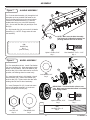
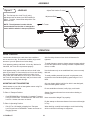
1
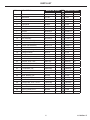
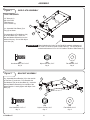
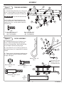
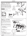
Owner's Manual
LAWN AERATOR
MODELS:
PA-40 BH
PA-48 BH
•
•
•
•
Assembly
Installation
Operation
Repair Parts
For use with Riders
and Lawn/Garden Tractors
IMPORTANT
This manual contains information for the safety
of persons and property. Read it carefully before
assembly and operation of the equipment!
For the latest product updates and setup tips:
Visit us on the web!
www.brinly.com
L-1762 Rev. E
INTRODUCTION
CONGRATULATIONS on the purchase of your new Brinly-Hardy Lawn
Aerator! Your lawn aerator is designed, engineered and manufactured to
give you the best possible dependability and performance.
CUSTOMER RESPONSIBILITIES
Please read and retain this manual. The instructions enables you to
assemble and maintain your lawn aerator properly. And please, always
observe the “Safety” instructions.
TABLE OF CONTENTS
SAFETY.......................................................................................... 2-3
PARTS REFERENCE . ......................................................................4
PARTS LIST.......................................................................................5
ASSEMBLY.................................................................................. 6-10
OPERATION AND MAINTENANCE ................................................11
WARRANTY .......................................................................Back page
PRODUCT COMPATIBILITY
This lawn aerator is designed for use with riders and lawn/garden
tractors.
RECORD PURCHASE INFORMATION
Record your purchase information in the spaces provided below:
DATE OF PURCHASE:
COMPANY NAME:
COMPANY PHONE:
SERIAL NUMBER:
SAFETY
SAFETY LABELS
UNDERSTANDING THE MACHINE SAFETY LABELS:
The machine safety labels shown in this section are placed in important
areas on your machine to draw attention to potential safety hazards.
On your machine safety labels, the words DANGER, WARNING, and
CAUTION are used with this safety-alert symbol. DANGER identifies the
most serious hazards.
The operator's manual also explains any potential safety hazards
whenever necessary in special safety messages that are identified with
the word, CAUTION, and the safety-alert symbol.
L-1762 Rev. E
2
SAFETY ALERT SYMBOL
SAFETY
TOWING SAFELY
TO HELP PREVENT BODILY INJURY DUE TO LOSS
OF STABILITY OR CONTROL:
• Do not exceed maximum towing capacity of towing vehicle
listed in the vehicle operator's manual.
• Stopping distance increases with speed and weight of
towed load. Travel slowly and allow extra time and distance
to stop.
• Do not tow this machine behind a motor vehicle such as a
car, truck or ATV.
• Total towed weight must not exceed limits specified in
towing vehicle operator's manual.
• Towing this machine behind a ZTR (Zero Turning Radius)
mower is not recommended due to the sharp turning ability
of the ZTR. Damage to this machine or the ZTR may result.
ZTR’s typically operate at higher speeds. Operating above 5
mph may result in damage to this machine.
• Excessive towed load can cause loss of traction and loss
of control on slopes. Reduce towed weight when operating
on slopes.
• Use only approved hitches. Tow only with a machine that
has a hitch designed for towing. Do not attach this machine
except at the approved hitch point.
SAFETY
• Follow the manufacturer's recommendations for weight
limits for towed equipment and towing on slopes. Use
counterweights or wheel weights as described in the towing
vehicle operator's manual.
Read the general safety operating precautions in your towing
vehicle operator's manual for additional safety information.
PROTECT BYSTANDERS
• Do not turn sharply. Use additional caution when turning or
operating under adverse surface conditions. Use care when
reversing. To avoid jack-knifing, do not allow towing vehicle
wheels to contact tow bar.
• Keep bystanders away when you operate this machine.
• Before you back look carefully behind for bystanders.
• Before you operate any feature of this machine, observe
your surroundings and look for bystanders.
• Do not shift to neutral and coast downhill.
OPERATE SAFELY
KEEP RIDERS OFF TOWED ATTACHMENT
• Use this machine for intended purpose only.
• Keep riders off towed attachment.
• This machine is intended for use in lawn care and home
applications.
• Riders on a towed attachment are subject to injury, such as
being struck by objects and being thrown off the attachment
during sudden starts, stops and turns.
• Do not tow behind a vehicle on a highway or in any high
speed applications. Do not tow at speeds higher than
maximum recommended towing speed.
• Riders obstruct the operator's view, resulting in the
attachment being used in an unsafe manner.
• Keep riders off of tow bar.
• Towing speed should always be slow enough to maintain
control. Travel slowly over rough ground.
KEEP BODY PARTS FROM UNDER TOW BAR
• Do not let children or an untrained person operate machine.
Before disconnecting this machine from towing vehicle hitch
plate:
• Do not let anyone, especially children, ride on this machine
or the towing vehicle.
• Stop on level ground.
• Stop towing vehicle engine.
• Lock towing vehicle park brake.
• Block wheels of the machine.
• Make sure body parts are not under tow bar.
• Check towing vehicle brake action before you operate.
Adjust or service brakes as necessary.
• Keep all parts in good condition and properly installed. Fix
damaged parts immediately. Replace worn or broken parts.
Replace all worn or damaged safety and instruction decals.
• Do not modify the machine or safety devices. Unauthorized
modifications to the towing vehicle or machine may impair its
function and safety, and void the warranty.
• Keep all nuts, bolts and screws tight.
3
L-1762 Rev. E
PARTS REFERENCE
17
29
2
32
24
7
24
8
20
24
21
18
5
32
22
31
7
32
32
32
4
20
31
8
20
26
24
15
9
10
26
13 15
32
26
32
12
27
15
11
19
14
28
16
25
22
STOP
L-1762 Rev. E
30
30
23
Installation Questions?
Missing Parts?
Replacement Parts?
DON’T GO BACK
TO THE STORE!
Please call Customer Service
Department Toll Free
877.728.8224 or
[email protected]
4
23
30
20
28
25
25
13
32
24
12
15
33
20
6
5
15
3
24
24
16
PARTS LIST
ITEM NO. DESCRIPTION
MODEL PA-40 BH
MODEL PA-48 BH
PART NO.
QTY.
PART NO.
QTY.
1
Instructions
L-1762
1
L-1762
1
2
Clevis
R-892-10
2
R-892-10
2
3
Caution Label
R-1946
1
R-1946
1
4
Logo Decal
B-5922
1
B-5925
1
5
Side Plate
B-4851-10
2
B-4901-10
2
6
Tray With Labels
B-6173-BH
1
B-6257-BH
1
7
Tow Bar
B-6259-10
2
B-6259-10
2
8
Hex Bolt, 5/16" x 1"
2M1016P
4
2M1016P
4
9
Plugging Spoon
B-4855-10
24
B-4855-10
32
10
Axle Assembly
B-5700-10
1
B-5702-10
1
11
Lift Handle Assembly
B-5698-10
1
B-5698-10
1
12
End Tube Assembly
B-5309-10
2
B-4862-10
2
13
Center Tube Assembly
B-5311-10
1
B-4865-10
2
14
Handle Grip
B-4867
1
B-4867
1
15
3/4" Nylon Bearing
B-4866
6
B-4866
8
16
Transport Wheel
B-6174
2
B-6174
2
17
Hitch Pin
B-3861
1
B-3861
1
18
Hair Pin Cotter
D-146P
1
D-146P
1
19
Hex Bolt, 5/16" x 1-1/2"
2M1024P
1
2M1024P
1
20
Hex Bolt, 5/16" x 3/4"
2M1012P
37
2M1012P
48
21
Hex Bolt, 5/16" x 1-1/4"
2M1020P
1
2M1020P
1
22
Hex Bolt, 5/8" x 4"
2M2064P
2
2M2064P
2
23
Lock Washer, 5/8"
40M2000P
2
40M2000P
2
24
Flat Washer, 5/16"
45M1111P
12
45M1111P
45
25
Flat Washer, 5/8"
45M2121P
4
45M2121P
4
26
Mach. Bushing, 3/4"
B-676P
6
B-676P
6
27
Transport Lock Pin
B-3307-S
1
B-3307-S
1
28
Hex Lock Nut, 5/16"
B-1674P
25
B-1674P
33
29
Carriage Bolt, 5/16" x 2-1/4"
11M1036P
2
11M1036P
2
30
Hex Nut, 5/8"
30M2000P
4
30M2000P
4
31
Mount Bracket
B-6171-10
2
B-6258-10
2
32
Nylon Lock Nut, 5/16"
B-4786
21
B-4786
24
33
Center Plate
N/A
N/A
B-4902-10
1
5
L-1762 Rev. E
ASSEMBLY
Figure 1
SIDE PLATE ASSEMBLY
TOOLS REQUIRED:
6
1/2" Wrench (2)
Slip Joint Pliers
Tape Measure
15/16" Wrench (2)
24
20
32
1a. Assemble Side Plates (5) to
Tray (6) as shown. 5
Pre-assemble the Flat Washers (24)
to the Hex Bolts (20). Insert the
Bolt and Washer Assembly from the
inside of the tray. Secure with Nylon
Lock Nuts (32).
32
IMPORTANT When tightening the bolts, for the PA-48 BH maintain a distance of
48" to 48-1/8" inside to inside of Side Plates (5). For the PA-40 BH
maintain a distance of 41" to 41-1/8" inside to inside of Side Plates (5).
(20)
Hex Head Bolt, 5/16" x 3/4"
Qty. 8
Figure 2
(32)
Nylon Lock Nut, 5/16"
Qty. 8
(24)
Flat Washer, 5/16"
Qty. 8
BRACKET ASSEMBLY
2a. Assemble Mount Bracket (31) to the outside
of Tow Bars (7) as shown. Pre-assemble the
Flat Washers (24) to the Hex Bolts (8). Insert the
Bolt and Washer Assembly from outside of the
Mount Bracket. Loosely tighten with Nylon Lock
Nuts (32).
31
8
32
24
24
8
7
(8)
Hex Head Bolt, 5/16" x 1"
Qty. 4
L-1762 Rev. E
(32)
Nylon Lock Nut, 5/16"
Qty. 4
6
(24)
Flat Washer, 5/16"
Qty. 4
ASSEMBLY
Figure 3
6
20
TOW BAR ASSEMBLY
20
3a. Assemble Mount Brackets (31) to Tray (6) as
shown. Insert the Bolts from the topside of the
Tray. Loosely tighten with Nylon Lock Nuts (32).
31
IMPORTANT Tray with label faces forward.
For PA-48 BH model install Center Plate (33)
to Tray (6) as shown. Insert the Bolts from the
topside of the Tray. Loosely tighten with Nylon
Lock Nuts (32).
32
31
33
32
32
32
7
(20)
Hex Head Bolt, 5/16" x 3/4"
Qty. 4 for PA-40 BH
Qty. 7 for PA-48 BH
Figure 4
(32)
Nylon Lock Nut, 5/16"
Qty. 4 for PA-40 BH
Qty. 7 for PA-48 BH
CLEVIS ASSEMBLY
17
29
7
4a. Assemble the Clevis (2) to Tow bars (7) as
shown. Install Carriage Bolts (29) and Nylon
Lock Nuts (32) finger tight. Next install Hex Bolt
(21) and Nylon Lock Nut (32) finger tight.
32
4b. Insert Hitch Pin (17) in Clevis (2) and secure
with Hairpin Cotter (18). Grasp Hitch Pin and pull
forward.
4c. Tighten securely all fasteners installed in step
4a. Then tighten securely all hardware installed
in Steps 2 through 3.
(32)
Nylon Lock Nut, 5/16"
Qty. 3
21
2
32
(18)
Hairpin Cotter, 1/8"
Qty. 1
18
Hex Bolt (21) Goes
Between The Two
Carriage Bolts (29)
29
(21)
Hex Head Bolt, 5/16" x 1-1/4"
Qty. 1
2
(29)
Carriage Bolt, 5/16" x 2-1/4"
Qty. 2
21
7
(17)
Hitch Pin
Qty. 1
7
L-1762 Rev. E
ASSEMBLY
Figure 5
TUBE ASSEMBLY
24
5a. Assemble Plugging Spoons (9) to each
welded plate (side opposite welds) of all the Tube
Assemblies (12 and 13) as shown. For PA-48H,
pre-assemble Hex Bolts (20) and Flat Washers
(24). NOTE: PA-40BH does not use Flat Washers. Install the Bolt (and Washer Assemblies) through
Plugging Spoons and secure with Lock Nuts (28).
IMPORTANT Rounded part of spoon fits
against the tube to lock in place.
20
(28)
Lock Nut, 5/16"
Qty. 24 for PA-40 BH
Qty. 32 for PA-48 BH
15
9
(24)
Flat Washer, 5/16"
Qty. 32 used on
PA-48 BH ONLY!
28
5b. Insert a Nylon Bearing (15) into each end of
the tube assemblies.
15
(15)
Nylon Bearing, 3/4" I.D.
Qty. 6 for PA-40 BH
Qty. 8 for PA-48 BH
Figure 6
13
(20)
Hex Head Bolt, 5/16" x 3/4"
Qty. 24 for PA-40 BH
Qty. 32 for PA-48 BH
TINE ASSEMBLY
6a. The End Tube Assemblies (12) have one
plate approximately 1-1/8" from the end of the
tube. The Center Tube Assemblies (13) have
each plate approximately 2-3/4" from the end of
the tube.
26
One or more Machinery Bushings as required to
eliminate any side play in axle assembly.
12
15
26
13
6b. Place a Machinery Bushing (26) over Axle
Assembly (10). Insert Axle Assembly through
Right Side Plate and install in the following order:
•
•
•
26
26
10
End Tube Assembly (12) with short hub end
next to side plate.
Machinery Bushing (26).
Center Tube Assembly (13).
5
For PA-48 BH only:
• Center Plate (33) and then another Center
Tube Assembly (13).
For all models:
• Machinery Bushing (26).
• End Tube Assembly (12) with short hub end
next to side plate.
(26)
• One or more Machinery Bushings (26) as
Machinery
Bushing, 3/4"
required to eliminate any side play in axle
Qty.
6
assembly.
L-1762 Rev. E
12
8
Make sure Nylon Bearings
(15) are inside Tube
Assemblies (Installed in Step 5b)
IMPORTANT
ASSEMBLY
Figure 7
HANDLE ASSEMBLY
7a. Push the Axle Assembly (10) through the left
side plate as far as possible and rotate so the
hole in the flat plate faces to the rear as shown. Install the Lift Handle Assembly (11) with the
welded tube facing out, to the Axle Assembly
(10). Secure with Hex Bolt (19) and Nylon Lock
Nut (32).
14
10
19
7b. Slip Handle Grip (14) over end of Lift Handle
Assembly (11). NOTE: Soapy water will ease
the assembly.
(14)
Handle Grip
Qty. 1
(Not To Scale)
Figure 8
NOTE: Make sure the Axle Assembly
Flat Plate and Lift Handle Assembly are
pointing towards the rear as shown.
32
11
(32)
Nylon Lock Nut, 5/16"
Qty. 1
(19)
Hex Head Bolt, 5/16" x 1-1/2"
Qty. 1
WHEEL ASSEMBLY
7a. Pre-assemble axle bolt. Install Flat Washer
(25) over Hex Bolt (22). Slide assembly through
wheel, note orientation. Place Flat Washer (25)
and Hex Nut (30) on Bolt and thread on as far as
possible, still allowing wheel to rotate freely.
7b. Install through holes in Lift Handle (11) and
Axle Assembly (10). Install Lock Washer (23)
and Hex Nut (30). Tighten inside Hex Nut while
holding Hex Nut next to wheel stationary.
32
27
16
(23)
Lock Washer, 5/8"
Qty. 2
22
25
25
7c. Insert Transport Pin (27) in rear hole same
side as Lift Handle Assembly (11) as shown. Secure with Nylon Lock Nut (32).
30
IMPORTANT: The wheel hub is offset to one
side. Make sure the extended offset is installed
toward plug aerator.
(32)
Nylon Lock Nut, 5/16"
Qty. 1
(30)
Hex Nut, 5/8"
Qty. 4
23 30
11
(27)
Transport Lock Pin
Qty. 1
(22)
Hex Bolt, 5/8" x 4"
Qty. 2
(25)
Flat Washer, 5/8"
Qty. 4
9
L-1762 Rev. E
ASSEMBLY
Figure 9
LEVELING
Adjust This Surface To Level
9a. The final step is to level Tray (6) using
adjustment bolts as shown here and installed in
Step 2. To adjust, loosen Bolts and position Tow
Bars until level.
Adjustment Bolts
To Tractor
NOTE: The adjustment is made with the
aerator attached to the rider or lawn/garden
tractor with the wheels in transport position.
OPERATION
WHEN TO AERATE
CAUTION
Your Aerator should not be used when lawn conditions
are too wet or too dry. To determine condition, dig a small
amount of your soil (about three inches deep):
After first thirty minutes of use check all fasteners for
tightness.
To avoid damage to spoons, always engage transport wheels
to raise the spoons when crossing concrete or asphalt walks,
drives, or roads.
If soil appears powdery and brittle- it is too dry. Wait until a
later date, the Tines will not penetrate properly.
If soil appears damp, roll a small amount into a ball in the
palm of your hand- if it forms a ball, then it is too wet. Ideally,
the soil should fall apart when rolled in the palm of your
hand. Wait until a later date for soil to dry. If soil is too wet,
the Tines will not operate effectively and your tractor could
loose traction, causing lawn damage.
Use the Aerator only on an established lawn, never on newly
laid sod.
MOUNTING AND TRANSPORTING
Only tow Aerator behind vehicles for which it was designed,
riders and lawn/garden tractors.
Attach aerator to your rider or lawn/garden tractor using Pin
and Hairpin Cotter Supplied.
Do not stand/ride on Aerator, bodily injury could result.
To Place in Transport Position:
Always disconnect Aerator from tractor when cleaning or
servicing unit.
•
To avoid possible personal injury and/ or equipment never
exceed the recommended operating speed range of 3 to 5
MPH.
Push REARWARD on Lift Handle (11) towards Transport
Lock Pin in Side Plate. Pull Handle OUT and mover over
Lock Pin. Aerator now rests on wheels.
Never exceed the Weight Tray capacity.
Do Not attempt to disconnect Aerator from tractor with weight
in Tray.
To Place in Operating Position:
•
When backing, carefully back straight to avoid Jack-knifing,
which could result in damage to equipment.
Pull OUT on Lift Handle (releasing from Transport
Lock Pin) and move FORWARD. Aerator now rests on
Plugging Spoons.
L-1762 Rev. E
10
MAINTENANCE
USE OF ADDITIONAL WEIGHT
Should rust develop, sand lightly and then paint area with
enamel.
The weight required to give a recommended penetration
of approximately two to three inches will vary according
to soil type and conditions. Concrete blocks, patio blocks,
sand bags, or any other type of weight can be added to
Aerator Tray as required. Weight can be secured by using
tie downs through holes in Tray Flanges. Tie downs are not
furnished with your unit. Usually three Concrete Blocks will
be sufficient, but more or less weight may be required.
•
•
•
•
Periodically check all fasteners for tightness.
IMPORTANT: Apply a drop of lubricating oil to each Nylon Bearing and the
Aerator Axle before each use.
To prevent rust on plugging spoons, apply a light coat of
oil on the working areas of spoons after each use. Should
rust appear on any other part of your Aerator, sand lightly to
remove rust and coat lightly with enamel.
Drive your tractor to location to be Aerated.
Lower Aerator to Operating Position.
Drive the Tractor FORWARD approximately ten feet and
stop.
Observe the operation- there should be a Plug hole
approximately every ten to twelve inches and not more
than three inches deep.
Add or remove weight to obtain this condition.
MAINTENANCE:
Plugging spoons are manufactured with special steels and
are heat treated to resist wear of abrasive soil. Striking
sub-surface objects can cause spoon breakage. Contact
our Customer Service Department to purchase replacement
Plugging Spoons (Part# B-4855-10). See “GETTING
QUALITY SERVICE”.
The key to years of trouble-free service is to keep your
Aerator clean and dry.
Periodically check the spoons remove any debris which
might build up and restrict their action.
Never allow wet material to remain in Tray for extended
periods of time.
After each use, service unit as described and store in a dry
area, shielding tines to avoid injury.
•
Occasionally check all moving parts for free movement and,
if necessary, lubricate with oil.
SPECIFICATIONS
PA-40
PA-48
Maximum Towing Speed.............................................. 5 MPH
Aerator Capacity..........................................................150 lbs.
Empty Weight................................................................66 lbs.
Maximum Towing Weight.............................................216 lbs.
Recommended Tire Pressure.........................Semi pneumatic
Maximum Towing Speed.............................................. 5 MPH
Aerator Capacity..........................................................200 lbs.
Empty Weight................................................................90 lbs.
Maximum Towing Weight.............................................290 lbs.
Recommended Tire Pressure.........................Semi pneumatic
SERVICE
Quality Continues With Quality Service
We provide a process to remedy your questions or problems.
Follow the steps below to get answers to any questions you may have about your product, or to order replacement parts:
1. Refer to your attachment and machine operator manuals.
2. In North America and Canada, call 1-877-728-8224 and provide product serial number and model number.
11
L-1762 Rev. E
MANUFACTURER'S LIMITED WARRANTY FOR
Pull Behind Accessories
The limited warranty set forth below is given by Brinly-Hardy
Company with respect to new merchandise purchased and
used in the United States, its possessions and territories.
Brinly-Hardy Company warrants the products listed below
against defects in material and workmanship, and will at
its option, repair or replace, free of charge, any part found
to be defective in materials or workmanship. This limited
warranty shall only apply if this product has been assembled,
operated, and maintained in accordance with the Operator’s
manual furnished with the product, and has not been subject
to misuse, abuse, commercial use, neglect, accident,
improper maintenance, alteration, vandalism, theft, fire,
water, or damage because of other peril or natural disaster.
Normal Wear Parts or components thereof are subject
to separate terms as follows: All normal wear parts or
component failures will be covered on the product for a
period of 90 days.
Parts found to be defective within the warranty period will
be replaced at our expense. Our obligation under this
warranty is expressly limited to the replacement or repair,
at our option, of parts found to be defective in material and
workmanship.
HOW TO OBTAIN SERVICE: Warranty parts replacements
are available, ONLY WITH PROOF OF PURCHASE, through
our Pull Behind Accessories Customer Service Department.
Call 877-728-8224.
This limited warranty does not provide coverage in the
following cases:
• Routine maintenance items such as lubricants and filters.
• Normal deterioration of the exterior finish due to use or
exposure.
• Transportation and/or labor charges.
• The warranty does not include commercial and/or rental
use.
No implied warranty, including any implied warranty
of merchantability of fitness for a particular purpose,
applies after the applicable period of express written
warranty above as to the part as identified below.
No other express warranty whether written or oral,
except as mentioned above, given by any person or
entity, including a dealer or retailer, with respect to
any product, shall bind Brinly-Hardy Co. During the
period of the warranty, the exclusive remedy is repair or
replacement of the product as set forth above.
L-1762 Rev. E
The provisions as set forth in this warranty provide
the sole and exclusive remedy arising from the sale.
Brinly-Hardy Co. shall not be liable for incidental or
consequential loss or damage including, without
limitation, expenses incurred for substitute or
replacement lawn care services or for rental expenses to
temporarily replace a warranted product.
Some states do not allow the exclusion or limitation of
incidental or consequential damages, or limitations on how
long an implied warranty lasts, so the above exclusions or
limitations may not apply to you.
During the warranty period, the exclusive remedy is
replacement of the part. In no event shall recovery of any
kind be greater that the amount of the purchase price of the
product sold. Alteration of safety features of the product shall
void this warranty. You assume the risk and liability for loss,
damage, or injury to you and your property and/or to others
and their property arising out of the misuse or inability to use
this product.
This limited warranty shall not extend to anyone other than
the original purchaser or to the person for whom it was
purchased as a gift.
HOW STATE LAW RELATES TO THIS WARRANTY: This
limited warranty gives you specific legal rights, and you may
also have other rights which vary from state to state.
IMPORTANT: The Warranty period stated below begins with
the PROOF OF PURCHASE. Without the proof of purchase,
the Warranty period begins from the date of manufacture
determined by the serial number manufacturing date.
SPREADER WARRANTY PERIOD:
The warranty period for this aerator is as follows: Steel frame
parts – 2 Years. Tires, wheels, and plugging spoons are
normal wear items - 90 days.