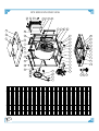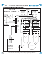
1
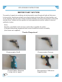
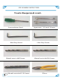
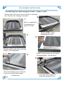
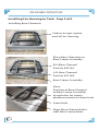
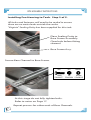
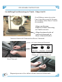
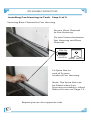
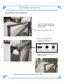
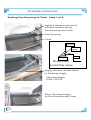
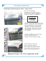
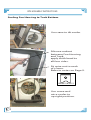
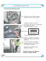
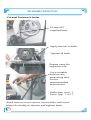
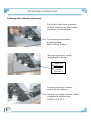
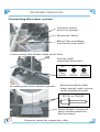
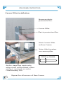
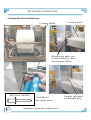
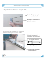
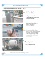
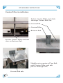
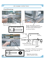
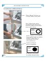
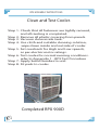
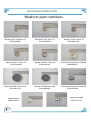
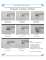
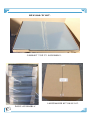
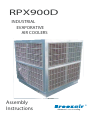
RPX900D
INDUSTRIAL
EVAPORATIVE
AIR COOLERS
Assembly
Instructions
Advanced natural cooling
RPX ASSEMBLY INSTRUCTIONS
INDEX
Description
Index
Important Notice/ Tools required
Installing Fan Housing to Tank 1/5
Installing Top Channel
Sealing Fan Housing to Tank 1/2
Sealing Fan Housing to Tank Bottom
Prepare Motor and Controls 1/4
Fan Pulley Attachment
Fit and Tension V Belts
Fitting the Water Pumps
Connecting the Water System
Corner Pillar Installation
Centre Rail Installation
Top Rail Installation 1/2
Bottom Rail Installation
Centre Pillar Installation
Water Spreader Installation
Distributor Cap Installation
Water Distributor Connection 1/2
Installing Cab Top Blanking Cover
Cabinet Top Installation 1/2
Squaring the Cooler
Cabinet Top Final Assembly 1/3
Final Riveting
Installing the Bleed Tap
Clean and Test Cooler
Washer Part Numbers
Bolt and Nut Part Numbers
Screw and Rivet Part Numbers
Panel Part Numbers
Miscellaneous Part Numbers 1/2
Special jig securing Flashing Angle
RPX 900 D Kit 1/2
RPX 900 D&T Pallet Specifications.
RPX 900 T Exploded View
3 Phase Wiring Diagram
2
Page
2
3
5
10
11
13
14
18
19
20
21
22
23
24
26
27
28
29
30
32
33
35
36
39
40
41
42
43
44
45
47
49
50
52
53
54
RPX ASSEMBLY INSTRUCTIONS
IMPORTANT NOTICE
The assembly of evaporative air conditioning units has the potential to create Occupational Health and Safety issues
for those involved. Assemblers are advised to ensure they are familiar with relevant State and Federal legislation, such
as Acts, Regulations, approved Codes of Practice and Relevant Standards, which offer practical guidance on these health
and safety issues. Companies with these regulations will require appropriate work practices, equipment, training and
qualification of workers.
Note:
Stainless steel bolts and nuts are used in the assembly of coolers.
A thread lubricating compound anti seize should be used at assembly.
(Anti Seize not supplied)
Tools Required
Pneumatic Drill.
Pneumatic Riveter
Long nose type.
3
Pneumatic Driver.
Pneumatic Silicone
Applicator.
RPX ASSEMBLY INSTRUCTIONS
Tools Required cont.
Screwdriver No3.
Hex Key 4mm.
Metal twist drill 5mm
4
Metal twist drill 12.5mm.
Spanners 10 and 13mm
Hex Key 5mm.
Metal twist drill 6.5mm
Pliers.
RPX ASSEMBLY INSTRUCTIONS
Installing Fan Housing to Tank. Step 1 of 5.
Select Base Frame and Tank Assembly
for Down discharge model.
2
1
Place supplied
Template to
top of Tank.
Align holes with
template bolts.
3
4
Mark with text pen, inside
edge of template.
5
Drill 6 mm hole to corners
of template. Total four.
6
Remove template, place
20 mm hole saw to 6mm
hole and drill through.
Total four.
5
Use Jig saw and cut
along marked line.
RPX ASSEMBLY INSTRUCTIONS
Installing Fan Housing to Tank. Step 2 of 5.
Installing Base Channels.
Tank to accept square
end of Fan Housing.
Place Base Channels on
Base Frame Assembly.
R/H Base Channel
Part No 623160.
L/H Base Channel
Part No 627168.
Base Frame Assembly.
Note:
Position of Base Channel
to Base Frame Assembly
Insert holes for motor
platform nearest to drain hole.
Drain Hole.
Align Base Channel holes
with Base Frame holes.
6
RPX ASSEMBLY INSTRUCTIONS
Installing Fan Housing to Tank. Step 3 of 5.
All holes and fasteners will need to be sealed to ensure
there are no water leaks outside the cooler.
"Virginia" Sealing Putty has been supplied for this task.
Place Sealing Putty to
Base Frame Assembly.
Clear hole before fitting
channel.
Base Frame Assy.
Secure Base Channel to Base Frame.
BOLT
M8x30
P/N0 628257
NUT
M8
8x19mm
P/No 628288 P/No WAS163
At this stage do not fully tighten bolts.
Refer to notes on Page 17.
Repeat process for other ends of Base Channels.
7
WASHER
RPX ASSEMBLY INSTRUCTIONS
Installing Fan Housing to Tank. Step 4 of 5.
Use lifting crane to raise
Fan Housing and H-Frame
Assembly over Base Frame
Assembly.
Align and lower
bottom of fan housing
to Tank cut out.
Align bottom hole of
vertical channel to
Base channel holes.
Secure Vertical Channel to Base Channel
H-Frame Vertical Channel.
BOLT
M8x20
P/N0 628240
NUT
WASHER
M8
8x19mm
P/No 628288 P/No WAS163
Note: 2 Bolts, 4 Washers and
2 Nuts per vertical Channel.
Base Channel.
8
Repeat process for other three vertical channels.
RPX ASSEMBLY INSTRUCTIONS
Installing Fan Housing to Tank. Step 5 of 5.
Securing Base Channel to Fan Housing.
Secure Base Channel
to Fan Housing.
Fix two Screws between
Fan Housing and Base
Channel.
SCREW - Phlp.
6x25 mm
P/No SCR 384
SPIRE NUT - P/No FAS115.
Fit Spire Nut to
end of Screws.
Inside of Fan Housing.
Note: The Spire Nut can
be fitted when Fan
Housing assembly is tilted.
Refer to notes on Page 13.
Repeat process for opposite side.
9
RPX ASSEMBLY INSTRUCTIONS
Installing Top Channel.
Install Top/Bearing
Channel to Vertical
Channels.
Part N/o 623139
Secure Channels.
Tighten all bolts.
BOLT
M8x20
P/N0 628240
NUT
WASHER
M8
8x19mm
P/No 628288 P/No WAS163
Repeat process for
other end.
10
Repeat process for opposite side.
RPX ASSEMBLY INSTRUCTIONS
Sealing Fan Housing to Tank. Step 1 of 2.
Apply a generous bead of
silicone sealant along
Fan Housing and Tank.
Fan Housing
Tank
FAN
HOUSING
FLASHING
ANGLE
SILICONE
TANK
Illustrated
assembly view.
Apply silicone sealant bead
to Flashing Angle.
Flashing Angle
P/No 100152
Place Flashing Angle
to Fan Housing and Tank.
11
RPX ASSEMBLY INSTRUCTIONS
Sealing Fan Housing to Tank. Step 2 of 2.
Secure Flashing
Angle to Fan Housing
and Tank, with supplied
screws: Total 10 places.
SCREW - Phlp.
4x25 mm
P/No SCR506
Note: If end of fan housing
bows inwards and cannot
be easily fixed, a special
clamp can be utilised to
aid fixing. P49 has details
to enable manufacture
of clamp.
Apply additional silicone
to top and bottom
edge of Flashing Angle.
Check that silicone
has a good seal to
Fan Housing and Tank.
Smooth out silicone to
give neat appearance.
12
Repeat Steps 1 & 2 for opposite side.
RPX ASSEMBLY INSTRUCTIONS
Sealing Fan Housing to Tank Bottom.
Use crane to tilt cooler.
Silicone sealant
between Fan Housing
and Tank,
apply thick bead to
all four sides.
Fit spire nut to ends
of screws.
Refer to notes on Page 9.
SPIRE NUT - P/No FAS 115.
Use crane and
raise cooler to
up right position.
13
RPX ASSEMBLY INSTRUCTIONS
Prepare Motor and Controls. Step 1 of 4.
Place Motor Platform to a
suitable work bench.
Note: Control box
mounting holes.
Place Control Box and
water pump assembly to
motor platform.
Securing Control Box
panel to Motor Platform.
BOLT
M6x20
P/N0 628226
14
NUT
WASHER
M6
6x14mm
P/No 628271 P/No WAS029
RPX ASSEMBLY INSTRUCTIONS
Prepare Motor and Controls. Step 2 of 4.
Use crane and fit electric
motor to platform,
align holes and
secure with
supplied fasteners.
Secure Motor to Platform.
BOLT
M8x30
P/N0 628257
NUT
M8
8x19mm
P/No 628288 P/No WAS163
Repeat for all 4 motor mounting bolts.
Ensure motor is square to Platform.
Tighten all bolts.
15
WASHER
RPX ASSEMBLY INSTRUCTIONS
Prepare Motor and Controls. Step 3 of 4.
Feed seven wires from the electrcal control box wiring
loom through the motor terminal cover opening.
Attach all wires and secure motor terminal cover.
Motor terminal cover.
Wiring loom to
electrical control box.
Gland
Wire connection.
For low speed connect.
Wire, tag numbered 1 to U1
2 to V1
3 to W1
For high speed connect.
Wire, tag numbered 4 to W2
5 to U2
6 to V2
Connect earth wire to motor casing earth point.
Cable tie wire loom
to Motor Platform.
16
RPX ASSEMBLY INSTRUCTIONS
Prepare Motor and Controls. Step 4 of 4.
Motor Pulley Attachment
The motor pulley attaches
to the motor shaft via a
Taper Lock Bush screwed
to the Pulley.
Do not fully tighten Bush
locking screws now, Pulley
may need to move on shaft
to align V-Belts.
Use crane to install
Motor Platform to
Base Channels.
Base Channel.
Secure Motor Platform to
Base Channels.
BOLT
WASHER
M8x30
P/N0 628257
8x25mm
P/No 627984
At this stage do not fully
tighten. Refer to notes
Belt Tension, P19.
17
Repeat same for
opposite side.
Note:
Fully tighten all Bolts securing
Base Channel to Base frame.
RPX ASSEMBLY INSTRUCTIONS
Fan Pulley Attachment.
Fit 460 mm Aluminium
Pulley to the fan shaft.
Apply small amount
Loctite 222 (not supplied)
to Grub screws.
Total 3 Grub screws.
GRUB SCREW
5/16 BSW 19 mm Long
P/No SCR433
Tighten All screws.
Allow shaft to extend
approx 15mm passed
pulley.
Use suitable straight
edge, align Fan Pulley
to Motor Pulley.
Align Fan Pulley and
Motor Pulley.
Lock Screws on Motor
Pulley Taper Bush.
18
RPX ASSEMBLY INSTRUCTIONS
Fit and Tension V-belts.
Fit two A91
supplied belts.
Apply tension to belts.
Tighten all bolts.
Repeat same for
opposite side.
Use a suitable
belt tension
measuring tool,
Set for
recommended
belt tension.
Deflection (cm) 1
Force (Kg) 1.5/1.7
If belt tension is not correct, loosen bolts and move
Motor Assembly, re-tension and tighten bolts.
19
RPX ASSEMBLY INSTRUCTIONS
Fitting the Water Pumps.
Position the two pumps
at the corner of the tank,
nearest control box.
Use pump brackets
as template
drill 4 mm holes.
Secure pumps with
supplied screws.
SCREW - Phlp.
5x19 mm
P/No 9610013
Ensure pumps leads
are out of water.
Secure pumps leads with
supplied cable ties,
P/No FAS 213.
20
RPX ASSEMBLY INSTRUCTIONS
Connecting the water system.
Connect water
hoses to pumps.
Restrictor Valve.
Bleed Tap assembly,
(see later notes p40).
Connecting the Water Inlet and Float
Secure with
supplied fasteners.
BOLT
M6x20
P/N0 628226
Installing the Anti-Vortex panels.
NUT
WASHER
M6
6x14mm
P/No 628271 P/No WAS029
Remove plastic film
from panel, and secure
with supplied rivets.
RIVET 5X12 mm P/No FAS 032
Note: Align Centre of
Anti-Vortex panel to
fan housing.
21
Repeat same for opposite side.
RPX ASSEMBLY INSTRUCTIONS
Corner Pillar Installation.
Remove plastic
protective film.
Corner Pillar.
Plastic protective film.
Rivet Corner Pillar
to Base Frame.
Note: Hole location
on corner pillar.
RIVET 5X12 mm P/No FAS 032
At this stage two rivets only,
other rivets will be fitted, when
cooler is squared, see notes
Final Riveting P39.
Repeat for all corners of Base Frame.
22
RPX ASSEMBLY INSTRUCTIONS
Centre Rail Installation.
Corner Pillar.
Centre Rail.
Align two tabs on
Centre Rail to slots
on Corner Pillar.
RIVET 5X12 mm P/No FAS 032
One Rivet,
for each end.
23
Repeat same for other end.
Apply silicone
to folded tag.
RPX ASSEMBLY INSTRUCTIONS
Top Rail Installation. Step 1 of 2.
Note: Tab at each
end of rail.
Remove protective
plastic cover.
Fit Universal Bracket to Top Rail
before fitting to Corner Pillar.
Rivet Universal
Bracket to Top Rail.
RIVET 5X12 mm P/No FAS 032
Two Rivets.
Universal Bracket
P/No 626567.
24
RPX ASSEMBLY INSTRUCTIONS
Top Rail Installation. Step 2 of 2.
Fit Top Rail to
Corner Pillar.
Align one tab on
Top Rail, to slots on
Corner Pillar.
Ensure Top Rail is
hard against
Corner Pillar.
Use suitable pliers
twist Top Rail end tab
inside Corner Pillar.
This to ensure that
assembly will not
dislodge.
Top Rail.
Centre Rail.
25
Repeat same for all Top Rails.
RPX ASSEMBLY INSTRUCTIONS
Bottom Rail Installation.
Bottom Rail.
Base Frame.
Place Bottom
Rail to inside edge
of Base Frame
and Rivet, to eight
points.
RIVET 5X12 mm P/No FAS 032
Repeat same for other three sides.
Completed Assembly
Top, Centre and Bottom Rails.
26
RPX ASSEMBLY INSTRUCTIONS
Centre Pillar Installation
Select Centre Pillar and slide
through Centre Rail slot.
Centre Rail.
Centre Pillar.
Bottom Rail.
Ensure Centre Pillar end tab
slots to Bottom Rail.
Slightly raise centre of Top Rail,
until Centre Pillar end tab
passes through slot.
Do not fold tab.
27
RPX ASSEMBLY INSTRUCTIONS
Water Spreader Installation.
Water Spreaders.
Align holes on Water
Spreader to Top Rail
and Rivet.
RIVET 3.2X8 mm P/No FAS 300
Repeat same for other three sides.
Water Distributor Cap.
28
RPX ASSEMBLY INSTRUCTIONS
Distributor Cap Installation.
Fit Distribution Cap
to top of Water
Spreader.
No securing is required,
ensure cap is tightly
pressed in position.
Repeat same for all
Water Spreaders.
Note: Position of
Distribution Cap to
Water Spreader.
Complete assembly of
Water Spreaders and
Distributor Cap.
Repeat same for other
three sides.
29
RPX ASSEMBLY INSTRUCTIONS
Water Distribution Connection. Step 1 of 2.
Cooler is fitted with two Water Pumps.
L/H side Water Pump
supply hose.
R/H side Water Pump
supply hose.
Typical hose connection
to Water Spreders Inlet.
8 places.
30
RPX ASSEMBLY INSTRUCTIONS
Water Distribution Connection. Step 2 of 2.
CONNECT
TO PUMP 1
1
Water Pump (2)
Supply hose.
CONNECT
TO PUMP 2
2
Fit saddle to secure four
way Distributor.
Typical Hose Connection to
Water Spreaders. D&T Models.
Hoses may
need to be
trimmed
to suitable
length.
Incorrect length
Water supply hose.
31
Hoses when fitted
should not touch pads.
Repeat same for All water supply Hoses.
RPX ASSEMBLY INSTRUCTIONS
Installing Cab Top Blanking Cover.
1
2
Remove film from cut out.
Select T Model Cabinet Top,
place to suitable work frame.
4
3
Fit Cab Top Blanking Cover.
Apply small bead of Silicone
along cut out inside line of
rivet holes.
6
5
Rivet Blanking Cover
to Cab Top.
Check alignment, for
rivet clearance holes.
32
RIVET 5X12 mm P/No FAS 032
RPX ASSEMBLY INSTRUCTIONS
Cabinet Top Installation. Step 1 of 2.
Place Cabinet Top onto Corner Pillars.
Note: Position of
Cabinet Top
joined section.
33
RPX ASSEMBLY INSTRUCTIONS
Cabinet Top Installation. Step 2 of 2.
Cabinet Top.
Remove plastic
protective cover
,
from corners of
Cabinet Top.
Rivet Cabinet
Top Corners.
RIVET 5X12 mm P/No FAS 032
At this stage two
rivets only.
Other rivets will be
added when cooler
is squared. See notes
Final Riveting P39.
Repeat same for all corners.
34
RPX ASSEMBLY INSTRUCTIONS
Squaring the Cooler for Final Assembly.
Use Supplied
Braces to
diagonally
square cooler.
Fit all 4 Braces
If necessary drill 5 mm hole
to clear aligning holes.
35
Distance between hole
centres 1868mm.
RPX ASSEMBLY INSTRUCTIONS
Cabinet Top Final Assembly. Step 1 of 3.
Top Channel.
Drill two 12.5mm holes
through Top Channel
and Cab Top.
Drill one 6mm hole
to centre Top Channel.
Note: Use 12.5 and
6 mm holes on Top
Channel as guide.
Repeat same for other side.
Place plastic Washers
between Cabinet Top
and Top Channel.
Place one Washers
at each end.
PLASTIC
FLAT WASHER
6.5X50X5MM
P/No WAS121
Two washers to centre.
Dome effect to Cab Top, for water run off.
PLASTIC
FLAT WASHER
13X50X5MM
P/No 608303
Top Channel.
36
Note: Number of washers may vary, between coolers.
RPX ASSEMBLY INSTRUCTIONS
Cabinet Top Final Assembly. Step 2 of 3.
Fit screw and washer,
to centre hole of Top
Channel, through to
plastic washers
and Top Channel.
SCREW - Phlp.
Washer
SPIRE NUT
6x50 mm
P/No SCR 507
6x14mm
P/No WAS029
P/No FAS 115.
Note: Position of Spire Nut.
Screw (air) driver.
Pliers.
Use suitable pliers to
hold Spire nut.
Secure Cabinet Top.
Repeat same for
opposite side.
37
RPX ASSEMBLY INSTRUCTIONS
Cabinet Top Final Assembly. Step 3 of 3.
Attach Lifting Eyenut
to Cooler
EYE NUT
WASHER
P/No 608358
14x25mm
P/No 802138.
Fit washer under Eyenut.
BOLT
M12x30
P/N0 608174
WASHER
13x44mm
P/No 608372
Fit bolt and washer,
thru 12.5 mm holes
in Top Channel,
through two plastic
Washers, Cabinet Top
and Eyenut.
Secure and tighten.
Repeat same for
other three lifting
Eyenuts.
When completed,
remove all
squaring braces.
38
RPX ASSEMBLY INSTRUCTIONS
Final Riveting
Rivet to four Cabinet
Top corners.
Rivet the four Corner
pillars at the Base Frame.
If necessary drill 5mm
to clear holes.
RIVET 5X12 mm P/No FAS 032
Cab Top
Nylon Washer.
Universal Bracket.
Fasten thru Cabinet
Top Rail and Bracket.
39
RIVET 5X18 mm
NYLON WASHER
P/No FAS 118
P/No 629872
Fit Nylon Washer between
Cab Top and Universal
Bracket.
Repeat same for
other three sides.
RPX ASSEMBLY INSTRUCTIONS
Installation of Bleed Valve.
Place Bleed Sticker on
Corner Pillar over hole
Pass bleed tap valve
through hole opening
and fit rubber Grommet
over valve body.
GROMMET
BLEED VALVE
P/No 999236
Note: Apply some White
Petroleum Jelly, or other
similar lubricant to
Grommet for ease
of installation.
Cable tie bleed
hoses together.
GROMMET
BLANK
P/No 626932
40
Fit Blank Grommet
to other three holes.
RPX ASSEMBLY INSTRUCTIONS
Clean and Test Cooler.
Step 1: Check that all fasteners are tightly secured,
and all riveting is completed.
Step 2: Remove all plastic covering from panels.
Step 3: Vacuum clean inside tank.
Step 4: Use cloth and suitable cleaning solution,
wipe down inside and outside of cooler.
Step 5: Set overloads for High and Low speeds,
as per electric motor ratings.
Step 6: Test cooler for normal running conditions.
refer to Appendix 1 - RPX Test Procedure
Step 7: Apply Serial Number to unit.
Step 8: Fit pads to cooler.
Completed RPX 900D
41
RPX ASSEMBLY INSTRUCTIONS
Washers part numbers.
Washer 5.6x11x 0.8mm. SS
P/No WAS031
Washer 6x14x1.2mm. SS
P/No WAS029
Washer 8x19x1.2mm. SS
P/No WAS163
Washer 9x25x1.5mm. SS
P/No WAS035
Washer 14x25x1.5mm. SS
P/No 802138
Washer13x44x2.5mm G/Bond
P/No 608372
Washer 6.5x50 x5mm Poly.
P/No WAS 121
Washer 13x50x5mm Poly.
P/No 608303
Washer 9x25x2.5mm G/Bond
P/No 627984
Nylon Washer
P/No 629872
42
Spire nut U type
P/No FAS115
RPX ASSEMBLY INSTRUCTIONS
Bolts and nuts part numbers.
Bolt M6x20. SS.
P/No 628226
Bolt M12x30. SS.
P/No 608174
Nut M6 Nyloc SS.
P/No 628271
43
Bolt M8x20. SS.
Bolt M8x30. SS.
P/No 628240
P/No 628257
Grub screw 5/16 BSW 19mm long.
P/No SCR433
Nut M8 Nyloc SS.
P/No 628288
Eyenut M12
P/No 608358
Note:
Stainless steel bolts and
nuts are used in the
assembly of coolers.
A thread lubricating
compound anti seize
should be used at assembly.
Anti Seize not supplied.
RPX ASSEMBLY INSTRUCTIONS
Screws and rivets part numbers.
Screw 19x5mm Phlp. SS.
Screw 50x6mm Phlp. SS.
P/No 9610013
P/No SCR507
P/No FAS118
P/No SCR506
44
P/No FAS300
P/No SCR 384
Rivet 5x18mm Al.
Wafer Screw 25x4mm Phlp.
Rivet 3.2x8mm Al.
Screw 25x6mm Phlp. SS.
Rivet 5x12mm Al.
P/No FAS032
Rivet 5x25mm Al.
P/No FAS204
RPX ASSEMBLY INSTRUCTIONS
Panels part numbers.
Bottom Rail
P/No 626789
Top Rail
P/No 626482
Centre Rail
P/No 626772
Anti Vortex
P/No 627229
Corner Pillar
P/No 626697
45
Universal Bracket
P/No 626567
RPX ASSEMBLY INSTRUCTIONS
Panels part numbers, cont.
Motor Platform
P/No 623184
Water spreader
P/No 506609
Flashing Angle.
P/No 100152
46
Centre Pillar
P/No 627892
Top/Bearing Channel
P/No 623139
Base Channel
R/H P/No 623160
L/H P/No 627168
RPX ASSEMBLY INSTRUCTIONS
Misc. part numbers.
Label Bleed Control.
Label O/Load Instructions.
P/No 998053.
P/No 025101
Grommet Blank.
Grommet Bleed Valve.
Cable Tie 140mm.
P/No 626932
P/No 999236
P/No FAS213.
125 x2A Mtr Pulley.
Bush Taper Lock..
460mm Pulley.
P/No 822044.
P/No 111500
P/No 626987.
47
Label Serial Number.
P/No 111500
RPX ASSEMBLY INSTRUCTIONS
Misc. part numbers, cont.
Overflow Assy.
P/No 609737.
2 Speed switch Assy.
P/No 626680
P/No 200103
A Section V Belts.
Silicone Sealant.
P/No Vba91.
P/No MIS508.
Down Discharge
Template cutout.
Distance between pin centres 1868mm.
Diagonally square braces.
48
Mounting block.
RPX ASSEMBLY INSTRUCTIONS
Special jig to assist when securing Flashing Angle
to Fan Housing.
Note: Cooler must be on pallet
Place tool to centre of cooler, lever upwards
to push inside of fan housing to flashing angle.
49
RPX 900 'D' KIT.
RESERVOIR, BASE FRAME AND ACCESSORIES.
50
FAN HOUSING AND 'H' FRAME ASSEMBLY.
RPX 900 'D' KIT.
CABINET TOP 'D' ASSEMBLY.
HARDWARE KIT 9655147.
51
PADS ASSEMBLY.
45
TEL (02) 60411611
FAX (02) 60412208
77 North Street, Albury N.S.W.
www.braemar.com.au
This drawing is the property of
Seeley International and must
not be reproduced or copied
without the written consent of
the proprietors of the copyright
Aspect packaging
Rough Sawn Pine
Z:\Vault\000000 To 169999\Part Files\100601
Part Loc:
Z:\Vault\000000 To 169999\Part Files\
Drawing Loc:
MATERIAL
SUPPLIER
DETAIL A
SCALE 1 : 5
BLANK
-
PRINTED: 15/07/2005
CHKD
PARTS/BLANK
-
DRN
UNIT REF
DESC
DP
10/08/1995
DATE
DRN
DP
RJK
RJK
1:1
A4
SHT
1
OF
100601
DRG NO
1
DP
REV
APP
ALL DIMENSIONS SHOWN ARE
OUTSIDE AND IN MILLIMETRES
UNLESS SHOWN OTHERWISE
SCALE
Pallet - 1560 x 1560
RPA/RPX 700/900
LINEAR ± 0.5mm ANGULAR ± 30'
FINISH: NATURAL U.O.S.
GENERAL TOLERANCE
REVISIONS
DATE
10/8/95
ECN
NA
DESCRIPTION
Production Release
REV.
A
4/12/98
Redrawn to curent specifications
B
24/03/2004
NA
3 Self drilling screws added to centre slats
C
1046
NOTE:
1. Pallet to be made from suitable timber unless otherwise specified.
2. Nails Min. 75mm glued type & punched below surface.
3. Sizes stated for slats & blocks are Min. required & to be parallel within
2mm of thickness.
4. Bearers to be free from defects, as shown by shaded area, that adversly
affect strength of pallet.
5. Any changes to pallet requires authorisation from Braemar Engineering.
6. Dimensions circled are critical.
100 ±2
65mm Self drilling
screws to be placed C
on each slat in areas
shown (3 in total)
100 x 20 Slats
5 per pallet
22
20
52
CL
1560
C
RPX PALLET SPECIFICATIONS
90
480
730
980
1560
53
627168
33
627236
111500
822044
608358
VBA91
627892
630342
100156
56
57
59
60
61
62
63
608907
53
626987
999293
52
55
523002
51
54
506609
626482
50
627229
48
49
620992
47
2
4
1
2
Vee Belt A91
Centre Pillar Grey
Blanking Plate - RPX "T" Cab Top
Flashing Strip Unpainted
4
Pulley Fan 450 (18") x 2A x 31.75 (1 1/4")
Eyebolt Nut M12
1
1
Pulley Motor 125 x 2A Taper
1
2
Bracket EBM Pu p
Bush TL 1610 x 38 #2
2
2
Pump EB 240V 50 Hz & J Box
8
Cap Spreader IND S all
Pump Basket Moulded
8
4
Water Spreader S all EA
Top Rail - Water Spreader
2
2
1
1
1
Panel Anti-Vortex RPX
Brace "H" Frame Ptd
Mount Isolation Box Painted
Motor 4.5kW 3 Phase 2 Speed
628981
Isolation Box 3Ph Large
46
1
1
Motor Platfor 700/900 Ptd
623184
58
100155
Bracket Water Inlet
616056
42
111221
Float Valve 1/2"
020803
41
44
1
Float 4"
020802
40
45
1
Shaft 1 1/4" x 960mm SS
1
2
Bearing Housing 1 1/4"
067003
100240
39
2
2
Bearing - 1 1/4 " inc Locking Collar
Rubber Insert 1 1/4"
1
1
1
Base Channel RH - Painted
Cut Off 16/19
4
Channel Bearing & Top Ptd
Blower Wheel Assy 16/19 1 1/4"
1
4
Channel - Vertical Painted
1
Blower Housing 16/19
Base Channel RH - Painted
1
4
Pillar Cnr Grey 82x82x64
1
Overflow Pipe 40mm
Washer Rubber 58*48
1
O Ring BS128 1 1/2" x 3/32"
1
1
Bush Funnel 1 1/2" BSP
Nut 1 1/2" BSP
6
Bracket Universal
38
067002
623139
32
067004
626710
31
36
623160
30
37
111401
29
100150
627922
28
111455
200105
35
608884
26
27
34
804415
25
626567
535500
628479
19
20
535401
628455
24
627915
17
18
23
Centre Rail - Painted Grey
627885
16
1
4
Label "Breezair" EA Pad Frame
515809
15
Cabinet Top Rear RPB1000"T"
16
Streaker No8 x 5/8 S/S
SCR266
14
1
128
Angle PFA 21 x 21 x 300mm
627823
13
4
16
16
Angle Bottom PFA 55 x 21 x 250mm
627809
12
Cabinet Top Common "T"
32
Angle PFA 55 x 21 x 545mm
627816
11
Bottom Rail GREY
16
Pad Frame EA S l Grey
505732
10
4
16
Pad -Small Celdek 597Wx585Hx60D
626727
9
1
Base Fra e Support
623948
8
2
Base Frame Assy - Painted
627854
7
1
855288
Label Breezair
623993
6
Channel - Reservoir Support
QTY
1
DESCRIPTION
Reservoir - Poly
2
P/N
100121
1
ITEM NO.
55
57
52
53
54
60
36 37 38
44
56
39
49
58
8
46
51
6
33
20
1
63
50
7
29
2
30
32
24
31
18
27
34
61
23
40
20
25
42
62
26
41
47
59
13
19
48
35
17
28
16
12
11
9
15
10
14
RPX 900D EXPLODED VIEW
INDUSTRIAL AIR CONDITIONERS
Advanced natural cooling
1
B R OW N
A1
A2
L3
1200-1800
B LUE
R PX
B LUE
WHIT E
L2
B LUE
W HIT E
B LAC K
GR E Y
RED
3
L1
B LAC K (Neutral)
2
F AN HI
F AN LO
AC T IV E
N
IS OLAT ING
S W IT C H
T O E AR T H
P OINT 1
GR E Y
C ool
3AG 250V
Lo/Hi
E
WHIT E
600-1000
TO
T E R MINAL
P OINT 6
2
5A F US E
1
C
2
RED
C
2
P UMP
C
MAINS IN
E
B LUE
R PX
RED
F an
1
L3 N
IS OLAT ING
S W IT C H
W ALL S W IT C H
1
L2
WHIT E
L1
RED
3 P HAS E
W IR ING DIAG R AM
RED
Wi
Wiring Diagram - Two Speed Three Phase.
A1
A2
RED
RPX
4
6
B LUE
7
1 L1
B LAC K
5
F IE LD W IR ING
3 L2
2 T1
B LA
5 L3
1 L1
21 NC
C ONT AC T OR
4 T2
6 T3
3 L2
5 L3
21 NC
C ONT AC T OR
22 NC
2 T1
4 T2
6 T3
22 NC
CK
8
GR E Y
T1
97
4
T2
6
2
GR E Y
95
98
T3
2
3
NO
96
T1
97
4
4
T2
98
6
5
54
E AR T H
(T O MOT OR P LAT F OR M)
W AT E R
P UMP
W AT E R P UMP
C ONNE C T ION
MODE LS
R P X 600
T O R P X 1800
T3
6
E AR T H
E AR T H
GR E Y
1
B R OWN
NC
GR E Y
2
96
GR E Y
95
12
OV E R LOAD
NO
GR E Y
NC
GR E Y
OV E R LOAD
11
B LUE
GR E Y
GR E Y
10
GR E Y
9
MOT OR
E AR T H
P OINT 1
It is the policy of Seeley International to introduce continual product improvement. Accordingly, specifications are subject to
change without notice. Please consult with your dealer to confirm the specifications of the model selected.
Manufacturers and Designers of Technically Advanced Quality Heating and Cooling Products...........Sept 2005