1
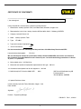
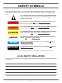
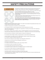
GT18B01
HYDRAULIC
POWER UNIT
WARNING
SAFETY, OPERATION AND MAINTENANCE
SERVICE MANUAL
Stanley Hydraulic Tools
3810 SE Naef Road
Milwaukie OR 97267-5698
503-659-5660
FAX 503-652-1780
www.stanley-hydraulic-tools.com
Copyright © 2004, The Stanley Works
OPS/MAINT USA
65466 9/2004 Ver 1
1
2
TABLE OF CONTENTS
SAFETY SYMBOLS ............................................................................................................................................................. 5
SAFETY PRECAUTIONS..................................................................................................................................................... 6
TOOL STICKERS & TAGS ................................................................................................................................................... 7
HYDRAULIC HOSE REQUIREMENTS................................................................................................................................ 8
HTMA REQUIREMENTS...................................................................................................................................................... 9
OPERATION....................................................................................................................................................................... 10
PREPARATION FOR USE ............................................................................................................................................... 10
CONTROLS........................................................................................................................................................................ 12
STARTUP ........................................................................................................................................................................... 12
FOR 5 GPM OPERATION ................................................................................................................................................ 12
FOR 8 GPM OPERATION ................................................................................................................................................ 12
COLD WEATHER STARTUP ........................................................................................................................................... 13
SHUTDOWN .................................................................................................................................................................... 13
ROUTINE MAINTENANCE ................................................................................................................................................ 14
STORAGE ........................................................................................................................................................................ 14
PROGRAMMABLE CONTROLLER ................................................................................................................................... 15
CALIBRATION .................................................................................................................................................................... 15
CHECKING PERFORMANCE CONTROL™ (ELECTRONIC GOVERNOR-STATIC CHECK) .......................................... 15
FAULT CODES ................................................................................................................................................................... 15
TESTING & TROUBLESHOOTING ................................................................................................................................... 17
GENERAL .......................................................................................................................................................................... 17
TESTING THE HYDRAULIC CIRCUIT .............................................................................................................................. 17
TESTING THE 5 GPM HTMA TYPE 1 CIRCUIT ................................................................................................................ 17
TROUBLESHOOTING ....................................................................................................................................................... 18
SPECIFICATIONS .............................................................................................................................................................. 19
SERVICE ............................................................................................................................................................................ 20
FIGURE 1. BRIGGS ENGINE ASSEMBLY ....................................................................................................................... 24
FIGURE 1. BRIGGS ENGINE PARTS LIST ...................................................................................................................... 25
FIGURE 2. FRAME PARTS .............................................................................................................................................. 26
FIGURE 3. HOSES, FITTINGS & CLAMPS ...................................................................................................................... 27
FIGURE 4B. MAIN POWER UNIT WIRING HARNESS .................................................................................................... 28
WARRANTY ....................................................................................................................................................................... 29
SERVICING THE STANLEY POWER UNIT: This manual contains safety, operation, and routine maintenance instructions. Stanley Hydraulic Tools recommends that servicing of hydraulic tools, other than
routine maintenance, must be performed by an authorized and certified dealer. Please read the following
warning.
WARNING
SERIOUS INJURY OR DEATH COULD RESULT FROM THE IMPROPER REPAIR OR SERVICE OF THIS TOOL.
REPAIRS AND / OR SERVICE TO THIS TOOL MUST ONLY BE
DONE BY AN AUTHORIZED AND CERTIFIED DEALER.
For the nearest authorized and certified dealer, call Stanley Hydraulic Tools at the number listed on the
back of this manual and ask for a Customer Service Representative.
3
CERTIFICATE OF CONFORMITY
Hydraulic Tools
______________________________________________________________________
I, the undersigned:
Burrows, James
Surname and First names
Hereby certify that the construction plant or equipment specified hereunder:
1. Manufacturer: Stanley Hydraulic Tools, 3810 Naef Road, Milwaukie, Oregon USA
2. Representative in the Union: Stanley Svenska AB, Box 9054, 400 92 Göteborg, SWEDEN
3. Category: Hydraulic Power Unit
4. Make:
Stanley Hydraulic Tools
5. Type:
GT18B01
6. Type serial number of equipment: ALL
7. Year of manufacture: Beginning 2004
Has been manufactured in conformity with the provisions of the Machinery Directive 98/37/EC
Harmonized standard applied:
EN 3744
We also declare that it meets the specification of Noise Directive 2000/14/EC, measured in accordance to
the Conformity Evaluation Method set out in Annex VI para. 5 and evaluated during production as in Annex
VI para. 6, 2nd procedure.
8. Noise related value: 13.25 Kw/18 hp
9. Measured sound power on equipment representative of this type: 100 LwA
10. Guaranteed sound power level for this equipment: 104 LwA
11. Notified body for EC directive 2000/14/EC:
0404
SMP Svensk Maskinprovning AB
Fyrisborgsgatan 3
754 50 Uppsala, SWEDEN
12. Special Provisions: None
Issued at Stanley Hydraulic Tools, Milwaukie, Oregon USA
Date: 8/24/04
Signature
Position: Engineering Manager
P/N 65472
4
Rev.1, 8/24/04
SAFETY SYMBOLS
Safety symbols and signal words, as shown below, are used to emphasize all operator, maintenance and repair
actions which, if not strictly followed, could result in a life-threatening situation, bodily injury or damage to equipment.
This is the safety alert symbol. It is used to alert you to potential personal
injury hazards. Obey all safety messages that follow this symbol to avoid
possible injury or death.
DANGER
This safety alert and signal word indicate an imminently hazardous situation which, if not avoided, will result in death or serious injury.
WARNING
This safety alert and signal word indicate a potentially hazardous situation
which, if not avoided, could result in death or serious injury.
CAUTION
This safety alert and signal word indicate a potentially hazardous situation
which, if not avoided, may result in minor or moderate injury.
CAUTION
This signal word indicates a potentially hazardous situation which, if not
avoided, may result in property damage.
NOTICE
This signal word indicates a situation which, if not avoided, will result in
damage to the equipment.
IMPORTANT
This signal word indicates a situation which, if not avoided, may result in
damage to the equipment.
Always observe safety symbols. They are included for your safety and for the protection of the tool.
LOCAL SAFETY REGULATIONS
Enter any local safety regulations here. Keep these instructions in an area accessible to the operator and maintenance personnel.
5
SAFETY PRECAUTIONS
Tool operators and maintenance personnel must always comply with the safety precautions given in this manual and on the stickers and tags attached to the equipment.
These safety precautions are given for your safety. Review them carefully before operating the tool and before performing general maintenance or repairs.
Supervising personnel should develop additional precautions relating to the specific
work area and local safety regulations. If so, place the added precautions in the space
provided on page 5.
In addition to this manual, read and understand safety and operating instructions in the
Engine Operation Manual furnished with the power unit.
The GT18B01 Hydraulic Power Unit will provide safe and dependable service if operated in accordance with the instructions given in this manual. Read and understand this
manual and any stickers and tags attached to the Power Unit. Failure to do so could
result in personal injury or equipment damage.
• Operator must start in a work area without bystanders. The operator must be familiar with all prohibited work areas such as
excessive slopes and dangerous terrain conditions.
• Establish a training program for all operators to ensure safe operation.
• Do not operate the power unit unless thoroughly trained or under the supervision of an instructor.
• Always wear safety equipment such as goggles, ear, head protection, and safety shoes at all times when operating the
power unit and a hydraulic tool.
• Do not inspect or clean the power unit while it is running. Accidental engagement of the unit can cause serious injury.
• Always use hoses and fittings rated at 2500 psi/172 bar with a 4 to 1 safety factor. Be sure all hose connections are tight.
• Be sure all hoses are connected for correct flow direction to and from the tool being used.
• Do not inspect hoses and fittings for leaks by using bare hands. “Pin-hole” leaks can penetrate the skin.
• NEVER OPERATE THE POWER UNIT IN A CLOSED SPACE. Inhalation of engine exhaust can be fatal.
• Do not operate a damaged, improperly adjusted power unit.
• Never wear loose clothing that can get entangled in the working parts of the power unit.
• Keep all parts of your body away from the working parts of the power unit.
• Keep clear of hot engine exhaust.
• Do not add fuel to the power unit while the power unit is running or is still hot.
• Do not operate the power unit if gasoline odor is present.
• Do not use flammable solvents around the power unit engine.
• Do not operate the power unit within 3.3 ft/1 m of buildings, obstructions or flammable objects.
• Do not reverse tool rotation direction by changing fluid flow direction.
• Allow power unit engine to cool before storing in an enclosed space.
• Always keep critical tool markings, such as labels and warning stickers legible.
• To avoid personal injury or equipment damage, all tool repair, maintenance and service must only be performed by authorized and properly trained personnel.
6
TOOL STICKERS & TAGS
62302
Power Unit Dash Decal
62300
Single Circuit
65458
Sound Power Decal
28322
CE Decal
DANGER
CHOKE
PULL TO START
PUSH TO RUN
62302
AUTO
IDLE
OFF
AUTO
IDLE
ON
RU
62300
7
HYDRAULIC HOSE REQUIREMENTS
HOSE TYPES
Hydraulic hose types authorized for use with Stanley Hydraulic Tools are as follows:
➊ Certified non-conductive
➋ Wire-braided (conductive)
➌ Fabric-braided (not certified or labeled non-conductive)
Hose ➊ listed above is the only hose authorized for use near electrical conductors.
Hoses ➋ and ➌ listed above are conductive and must never be used near electrical conductors.
HOSE SAFETY TAGS
To help ensure your safety, the following DANGER tags are attached to all hose purchased from Stanley Hydraulic Tools. DO NOT REMOVE THESE TAGS.
If the information on a tag is illegible because of wear or damage, replace the tag immediately. A new tag may be
obtained from your Stanley Distributor.
D A N G E R
D A N G E R
1 FAILURE TO USE HYDRAULIC HOSE LABELED AND CERTIFIED AS NON-CONDUCTIVE
WHEN USING HYDRAULIC TOOLS ON OR NEAR ELECTRIC LINES MAYRESULT IN DEATH
OR SERIOUS INJURY.
FOR PROPER AND SAFE OPERATION MAKE SURE THAT YOU HAVE BEEN PROPERLY
TRAINED IN CORRECT PROCEDURES REQUIRED FOR WORK ON OR AROUND
ELECTRIC LINES.
3. DO NOT EXCEED HOSE WORKING PRESSURE OR ABUSE HOSE. IMPROPER USE OR
HANDLING OF HOSE COULD RESULT IN BURST OR OTHER HOSE FAILURE. KEEP
HOSE AS FAR AWAY AS POSSIBLE FROM BODY AND DO NOT PERMIT DIRECT CONTACT
DURING USE. CONTACT AT THE BURST CAN CAUSE BODILY INJECTION AND SEVERE
PERSONAL INJURY.
4. HANDLE AND ROUTE HOSE CAREFULLY TO AVOID KINKING, ABRASION, CUTTING, OR
CONTACT WITH HIGH TEMPERATURE SURFACES. DO NOT USE IF KINKED. DO NOT USE
HOSE TO PULL OR LIFT TOOLS, POWER UNITS, ETC.
2. BEFORE USING HYDRAULIC HOSE LABELED AND CERTIFIED AS NON-CONDUCTIVE ON
OR NEAR ELECTRIC LINES. WIPE THE ENTIRE LENGTH OF THE HOSE AND FITTING
WITH A CLEAN DRY ABSORBENT CLOTH TO REMOVE DIRT AND MOSISTURE AND TEST
HOSE FOR MAXIMUM ALLOWABLE CURRENT LEAKAGE IN ACCORDANCE WITH SAFETY
DEPARTMENT INSTRUCTIONS.
5. CHECK ENTIRE HOSE FOR CUTS CRACKS LEAKS ABRASIONS, BULGES, OR DAMAGE TO
COUPLINGS IF ANY OF THESE CONDITIONS EXIST, REPLACE THE HOSE IMMEDIATELY.
NEVER USE TAPE OR ANY DEVICE TO ATTEMPT TO MEND THE HOSE.
6. AFTER EACH USE STORE IN A CLEAN DRY AREA.
SIDE 1
3
DO NOT REMOVE THIS TAG
DO NOT REMOVE THIS TAG
THE TAG SHOWN BELOW IS ATTACHED TO “CERTIFIED NON-CONDUCTIVE” HOSE
SIDE 2
(shown smaller than actual size)
D A N G E R
D A N G E R
1 DO NOT USE THIS HYDRAULIC HOSE ON OR NEAR ELECTRIC LINES. THIS HOSE IS
NOT LABELED OR CERTIFIED AS NON-CONDUCTIVE. USING THIS HOSE ON OR NEAR
ELECTRICAL LINES MAY RESULT IN DEATH OR SERIOUS INJURY.
5. CHECK ENTIRE HOSE FOR CUTS CRACKS LEAKS ABRASIONS, BULGES, OR DAMAGE TO
COUPLINGS IF ANY OF THESE CONDITIONS EXIST, REPLACE THE HOSE IMMEDIATELY.
NEVER USE TAPE OR ANY DEVICE TO ATTEMPT TO MEND THE HOSE.
2. FOR PROPER AND SAFE OPERATION MAKE SURE THAT YOU HAVE BEEN PROPERLY
TRAINED IN CORRECT PROCEDURES REQUIRED FOR WORK ON OR AROUND
ELECTRIC LINES.
6. AFTER EACH USE STORE IN A CLEAN DRY AREA.
3. DO NOT EXCEED HOSE WORKING PRESSURE OR ABUSE HOSE. IMPROPER USE OR
HANDLING OF HOSE COULD RESULT IN BURST OR OTHER HOSE FAILURE. KEEP
HOSE AS FAR AWAY AS POSSIBLE FROM BODY AND DO NOT PERMIT DIRECT CONTACT
DURING USE. CONTACT AT THE BURST CAN CAUSE BODILY INJECTION AND SEVERE
PERSONAL INJURY.
4. HANDLE AND ROUTE HOSE CAREFULLY TO AVOID KINKING, CUTTING, OR CONTACT
WITH HIGH TEMPERATURE SURFACES. DO NOT USE IF KINKED. DO NOT USE HOSE TO
PULL OR LIFT TOOLS, POWER UNITS, ETC.
DO NOT REMOVE THIS TAG
DO NOT REMOVE THIS TAG
THE TAG SHOWN BELOW IS ATTACHED TO “CONDUCTIVE” HOSE.
SEE OTHER SIDE
SIDE 1
SIDE 2
(shown smaller than actual size)
HOSE PRESSURE RATING
The rated working pressure of the hydraulic hose must be equal to or higher than the relief valve setting on the
hydraulic system.
8
HTMA REQUIREMENTS
TOOL CATEGORY
HYDRAULIC SYSTEM
REQUIREMENTS
TYPE I
TYPEII
TYPEIII
TOOL OPERATING PRESSURE
(at the power supply outlet)
4-6 gpm
(15-23 lpm)
2000 psi
(138 bar)
7-9 gpm
(26-34 lpm)
2000 psi
(138 bar)
11-13 gpm
(42-49 lpm)
2000 psi
(138 bar)
SYSTEM RELIEF VALVE SETTING
(at the power supply outlet)
2100-2250 psi 2100-2250 psi 2100-2250 psi 2200-2300 psi
(145-155 bar) (145-155 bar) (145-155 bar) (152-159 bar)
MAXIMUM BACK PRESSURE
(at tool end of the return hose)
250 psi
(17 bar)
Measured at a max. fluid viscosity of:
(at min. operating temperature)
400 ssu*
400 ssu*
400 ssu*
400 ssu*
(82 centistokes) (82 centistokes) (82 centistokes) (82 centistokes)
TEMPERATURE
Sufficient heat rejection capacity
to limit max. fluid temperature to:
(at max. expected ambient temperature)
140° F
(60° C)
140° F
(60° C)
140° F
(60° C)
140° F
(60° C)
Min. cooling capacity
at a temperature difference of
between ambient and fluid temps
3 hp
(2.24 kW)
40° F
(22° C)
5 hp
(3.73 kW)
40° F
(22° C)
7 hp
(4.47 kW)
40° F
(22° C)
6 hp
(5.22 kW)
40° F
(22° C)
FLOW RATE
250 psi
(17 bar)
250 psi
(17 bar)
TYPE RR
9-10.5 gpm
(34-40 lpm)
2000 psi
(138 bar)
250 psi
(17 bar)
NOTE:
Do not operate the tool at oil temperatures above 140° F (60° C). Operation at higher temperatures can cause operator
discomfort at the tool.
FILTER
25 microns
Min. full-flow filtration
30 gpm
Sized for flow of at least:
(114 lpm)
(For cold temp. startup and max. dirt-holding capacity)
25 microns
30 gpm
(114 lpm)
HYDRAULIC FLUID
Petroleum based
(premium grade, anti-wear, non-conductive)
VISCOSITY
(at min. and max. operating temps)
100-400 ssu* 100-400 ssu*
(20-82 centistokes)
100-400 ssu*
25 microns
30 gpm
(114 lpm)
25 microns
30 gpm
(114 lpm)
100-400 ssu*
NOTE:
When choosing hydraulic fluid, the expected oil temperature extremes that will be experienced in service determine the
most suitable temperature viscosity characteristics. Hydraulic fluids with a viscosity index over 140 will meet the requirements over a wide range of operating temperatures.
*SSU = Saybolt Seconds Universal
NOTE:
These are general hydraulic system requirements. See tool Specification page for tool specific requirements.
9
OPERATION
PREPARATION FOR USE
Chevron AW-MV-32
Exxon "Univis" J-26
Mobil D.T.E. 13
Gulf "Harmony" AW-HVI-150-32
Shell "Tellus" T-32
Texaco "Rando" HD-AZ
Union "Unax" AW-WR-32
Terresolve EnviroLogic 132
Do not operate the power unit until you have read the
engine operating and maintenance instructions manual
furnished with the unit.
1. ENGINE CRANKCASE OIL LEVEL
Always check the oil level before starting the engine. Make
sure the oil level is at the FULL MARK on the dipstick. Do
not overfill. Use detergent oil classified "For Service SE, SF,
SG" as specified in the engine operating and maintenance
manual. See engine manual for oil viscosity grade.
4. HYDRAULIC CONNECTIONS
The recommended hose length is 25 ft/8 m with a 1/2
inch/12.7 mm inside diameter. The hoses must have a
working pressure rating of at least 2500 psi/175 bar. Each
hose end must have male thread ends compatible with
H.T.M.A. (HYDRAULIC TOOL MANUFACTURERS ASSOCIATION) quick disconnect fittings (NPT type threads).
(See Figure 2.)
2. ENGINE FUEL LEVEL
Check the fuel level. If low, fill with un-leaded gasoline with
a minimum of 85 octane.
3. HYDRAULIC FLUID
Check the dip stick in the hydraulic fluid reservoir for the
proper fiuid level. Use fluids meeting the following specifications.
Viscosity (Fluid Thickness)
U.S.
METRIC
Figure 1. Panel Control Valve
50°F 450 SSU Maximum
100°F 130-200 SSU
140°F 85 SSU Minimum
10°C 95 C.S.
38°C 27-42 C.S.
60°C 16.5 C.S. Min
Pour Point -10°F/-23°C Minimum (for cold startup)
Facing the panel control valve, the bottom male quick
disconnect fitting is the PRESSURE FLUID OUT fitting. The
top female quick disconnect fitting is the RETURN FLUID
IN fitting.
Viscosity Index (ASTM D-2220) 140 Minimum
QUICK DISCONNECT COUPLERS
Demulsibility (ASTM D-1401) 30 Minutes Maximum
H.T.M.A. approved quick disconnect couplings are installed
to hydraulic hoses so that the direction of oil flow is always
from the male to the female quick disconnect as shown in
figure 2. Quick disconnect couplings and hose fittings are
selected so that additional fittings such as reducer or adapter fittings are not required.
Flash Point (ASTM D-92) 340°F/171°C Minimum
Rust Inhibition (ASTM D-665 A & B) Pass
Oxidation (ASTM D-943) 1000 Hours Minimum
If adapter fittings are used, they must be approved steel
hydraulic fittings meeting a minimum operating pressure
rating of 2500 psi/172 bar. Do not use galvanized pipe fittings or black pipe fittings.
Pump Wear Test (ASTM D-2882) 60 mg Maximum
The following fluids work well over a wide temperature
range, allow moisture to settle out and resist biological
growth that may occur in cool operating hydraulic circuits.
These fluids are recommended by Stanley. Other fluids
that meet or exceed the specifications of these fluids may
also be used.
Use thread tape or pipe joint compound when installing
quick disconnect couplings to hose or tool fittings. Follow
the instructions furnished with the selected thread sealant.
10
OPERATION
DO NOT OVERTIGHTEN THE FITTINGS.
CONTROL PANEL
5. BATTERY
The supplied 12 Volt DC battery is a non-spillable, maintenance-free battery and is fully charged.
RETURN
PRESSURE
H.T.M.A. 1/2 INCH FEMALE QUICK DISCONNECT COUPLER
Make sure the battery cables are tight and charging circuit
functions are operating properly.
H.T.M.A. 1/2 INCH MALE
QUICK DISCONNECT
COUPLER
NOTICE
1/2 INCH MALE PIPE HOSE END
Do not charge the battery with a standard automotive battery charger. This type of charger produces a charging amperage higher than 2 amps.
Charging the battery at higher than 2 amps will
damage the battery.
1/2 INCH I.D. HOSE, 25 FT
LONG WITH 2500 PSI/
172 BAR RATING AND
4 TO 1 SAFETY FACTOR
NOTICE
RETURN
PRESSURE
If the engine runs out of gas or dies during operation and the ignition switch is left in the ON or
RUN position, this could drain the battery. Make
sure the ignition switch is returned to the OFF
position.
1/2 INCH MALE PIPE HOSE END
H.T.M.A. 1/2 INCH FEMALE QUICK DISCONNECT COUPLER
H.T.M.A. 1/2 INCH MALE
QUICK DISCONNECT
COUPLER
ADAPTER, 3/8 INCH MALE PIPE x
-8 SAE O-RING
PRESSURE
TOOL
RETURN
Figure 2. Hydraulic Connections
11
OPERATION
At times it may be neccessary to reset the controller. This
could happen if a fault occurs in the controller. For example, excessive engine speed. If a fault does occur the
power unit will return to an idle and the operator will have
no control of the unit. To reset the controller, simply turn off
the power unit and restart it.
CONTROLS
This unit is equipped with an advanced proportional engine
control system. It provides a means of controlling engine
speed by adjusting the fuel control lever with an actuator.
The Power Unit provides one circuit, with an oil flow of 5
gpm/19 lpm up to 2000 psi/140 bar or 8 gpm/30 lpm up
to 2000 psi/140 bar with a factory-programmed electronic
governed engine throttle.
STARTUP
Before starting the engine make sure the flow selector
switch is in the OFF position.
Note:
The power unit will not start if the flow control switch is
not in the "OFF" position.
THROTTLE CONTROL
SWITCH
FLOW SELECTOR
SWITCH
Pull choke knob out and move the Throttle Control Switch
to the auto-idle-off or the auto-idle-on position, whichever
mode of operation the operator prefers. Ensure the flow
selector switch is in the OFF position.
IGNITION SWITCH
Figure 3. Panel Control Valve
Turn the Ignition Switch to the START position. After the
engine starts, release the switch.
One hydraulic tool can be connected to the tool circuit.
The circuit is activated by turning the flow control switch to
either the 5 gpm/19 lpm or 8 gpm/30 lpm setting.
Gradually push in the choke knob as the engine begins to
idle smoothly.
THROTTLE CONTROL
The throttle control permits the operator to select one of 2
operating modes after the engine has warmed up. When
starting the engine, make sure the flow selector switch is in
the OFF position. The throttle control switch can be set in
either the AUTO-IDLE-ON or AUTO-IDLE-OFF positions.
Allow the engine to warm up.
Connect hoses and the tool as desrcribed on pages 9 and
10.
AUTO-ON
When the throttle control switch is in the "AUTO-ON" position, the oil flow is regulated automatically when the trigger
on the tool activated. When the tool is not being used the
engine will return to idle automatically, after a 10 second
delay.
FOR 5 GPM OPERATION
This setting will produce 5 gpm/19 lpm or 8 gpm/30 lpm
depending on which postion the operator has selected with
the flow selector switch.
When finished operating the tool, move the flow selector
switch to the OFF position.
For 5 gpm operation, select mode of operation with the
Throttle Control switch, either auto-idle-on or the auto-idleoff position. Move the flow selector switch to the 5 gpm
position.
FOR 8 GPM OPERATION
AUTO-OFF
When the throttle control switch is in the "AUTO-OFF" position, the engine speed is held to maintain 5 gpm/19 lpm or
8 gpm/30 lpm depending on which position the operator
has selected with the flow selector switch. When a tool is
not being used the engine will not return to idle until either
the flow selector switch is turned to the OFF position or the
throttle control switch is turned to AUTO-ON.
For 8 gpm operation, select mode of operation with the
Throttle Control Switch, either auto-idle-on or the auto-idleoff position. Move the flow selector switch to the 8 gpm
position.
When finished operating the tool, move the flow selector
switch to the OFF position.
Note:
It may be necessary to reset the Controller.
12
OPERATION
COLD WEATHER STARTUP
1. Use the procedures described under "STARTUP" and
then follow the procedure below.
2. Hydraulic fluids are thicker in cold weather. Therefore,
it is recommended that the engine be run at low idle long
enough to bring the fluid temperature up to a minimum of
50°F/10°C.
3. If the tools and tool hoses are cold, it is recommended
to allow hydraulic fluid to circulate through the tool hoses
until warm before using the tool.
SHUTDOWN
1. Ensure the flow selector switch in the OFF position
(center position).
2. Unless already at idle the power unit should return to
idle. This may take a few seconds for the unit to react due
to a built-in program delay.
3. Allow the engine to idle for approximately one minute
and move the Ignition Switch to the OFF position.
13
ROUTINE MAINTENANCE
ENGINE MAINTENANCE
STORAGE
Follow the maintenance schedule and general maintenance
instructions in the engine maintenance and operation
manual furnished with the power unit.
• Clean the unit thoroughly before storage. Do not use
water pressure.
HYDRAULIC SYSTEM MAINTENANCE
• Always store the unit in a clean and dry facility.
• Check hydraulic fluid level daily. Add fluid per specifications in this manual. (See "HYDRAULIC FLUID" under the
section titled "OPERATING INSTRUCTIONS".
• If the unit will be stored for a prolonged period (over 30
days), add a fuel additive to the fuel tank to prevent the fuel
from gumming. Run engine for a short period to circulate
the additive.
• Remove condensed moisture from the hydraulic
fluid by pumping the hydraulic fluid into a 5 gal/20 l container through the pressure hose. Make sure the engine is
at idle when performing this procedure. When the hydraulic
reservoir is empty turn the engine off immediately.
• Replace crankcase oil with new oil.
• Remove spark plugs and pour approximately 1 ounce (30
ml) of engine oil into each cylinder. Replace spark plugs
and crank the engine slowly to distribute the oil.
• Allow the fluid to sit long enough for the water to settle to
the bottom of the container. Slowly pour the fluid back into
the hydraulic tank, avoiding the water at the bottom of the
container.
• Check hydraulic reservoir for water. If water is found,
change the oil and circulate it through the tool hose and
tool. (See "HYDRAULIC SYSTEM MAINTENANCE" earlier
in this section).
• Each day, check hydraulic lines and fittings for leaks,
kinks, etc. Do not use your hand to perform this check.
• Disconnect tool hoses.
• Change the hydraulic filter element every 200 hours of
operation. Change more often if cold, moist or dusty conditions exist.
• Check oil cooler for debris. Remove debris with air pressure.
14
PROGRAMMABLE CONTROLLER
CHECKING PERFORMANCE CONTROL™
(ELECTRONIC GOVERNOR-STATIC CHECK)
The Stanley programmable controller is an electronic
engine governor that provides a means of controlling and
limiting engine speed by adjusting the fuel control lever with
a proportional actuator.
To determine whether a governor problem is being caused
by the actuator or the control module, perform the following
static check exactly in order shown.
The controller is software programmable and has no
manual adjustments.
A pair of jumper wires and a known good 12-volt battery is
required.
1. Disconnect red and green wires from the control module
to actuator.
A flashing LED indicates
the fault condition
2. Attach jumper wires from battery to RED and GREEN
wires to actuator.
a. Attach 12 volt + (positive) to RED wire.
b. Attach 12 volt – (negative) to GREEN wire.
3. Actuator should move throttle lever to wide open position.
CALIBRATION
a. If actuator does not move it is defective. (Replace).
b. If actuator moves throttle to wide-open position, the
module is defective. (Replace).
ACT is a PC (personal computer) based software
calibration and monitoring tool. ACT is designed
specifically for use with engines equipped with
the Stanley controller. Stanley Hydraulic Tools
recommends that an authorized and certified
dealer perform calibration of this unit.
FAULT CODES
The Stanley controller is capable of identifying certain fault
conditions and alerting the user to them. A flashing LED
indicates the fault conditions. The current fault code list is
shown on the following page. Please note the following:
Once the controller has been programmed, ACT
may be disconnected. The Stanley controller
will continue to operate normally with ACT either
connected or disconnected.
1. When power is first applied to the controller, the LED will
flash just once for one second to indicate that the LED is
working.
TROUBLESHOOTING GUIDELINES
2. If there are multiple faults, the LED will flash them all
in sequence. Count the flash codes to determine the fault
conditions or connect the Calibration Tool to observe the
fault conditions. (Use the “Display Faults” option under the
Monitor Menu.)
Please follow the checklist below to troubleshoot your Stanley controller.
1. Check battery voltage for stability and correct value. The
LED will turn on for one second when the controller 4500 is
first powered up.
3. If there are no faults, the LED will flash once at reset
and from then on indicate the detection of engine speed. A
continuous ON LED indicates that a valid engine speed is
being sensed.
2. Check the actuator linkage for binding and backlash.
4. The controller will attempt to shut down for some faults
and will not permit starting after reset with faults 1, 5 and 8.
15
FAULT CODES
FLASH
CODE
FAULT
ENGINE
SHUTDOWN
CORRECTIVE ACTION
1
APECS unit not calibrated
yes
Have engine serviced by an Authorized Stanley Dealer.
2
Engine speed excessive
yes
Have engine serviced by an Authorized Stanley Dealer.
3
Engine speed unusually low
yes
Have engine serviced by an Authorized Stanley Dealer.
4
Engine shutdown due to engine
protection input
yes
Have engine serviced by an Authorized Stanley Dealer.
5
Factory settings lost
yes
Have engine serviced by an Authorized Stanley Dealer.
6
External pot out-of-range
no
Have engine serviced by an Authorized Stanley Dealer.
7
Accelerator position / idle
switch conflict
no
Have engine serviced by an Authorized Stanley Dealer.
8
Controller unit failed
yes
Have engine serviced by an Authorized Stanley Dealer.
9
Limiting excessive
actuator current
no
Have engine serviced by an Authorized Stanley Dealer.
10
Engine speed input
signal missing
no
(Active only in Auto crank mode).
Check speed sensor wiring.
Check starter motor.
11
Auto crank unable to
start engine
no
Check fuel.
12
Auxiliary output is shorted
no
Check the lamp or relay hooked to the output. If fault is
still present, have engine serviced by an authorized
Stanley Dealer.
13
Auxiliary output #2 is shorted
no
Check the lamp or relay hooked to the output. If fault is
still present, have engine serviced by an authorized
Stanley dealer.
14
Actuator disconnected or
open circuit
no
Check actuator wiring and actuator resistance.
Resistance should be less than 10 ohms.
16
TESTING & TROUBLESHOOTING
begins to open is commonly referred to as the "cracking
pressure". At the "cracking pressure," the flow rate should
start to drop because the relief valve is allowing fluid to bypass to the hydraulic reservoir. The "cracking pressure" is
preset at the factory and if it is not within the above range,
the relief valve must be re-set as follows:
GENERAL
Tests and adjustments should be performed periodically to
ensure the power unit is operating at maximum efficiency.
Stanley Circuit Tester (part number 04182) is recommended. This tester can be used to isolate problems in both the
engine and hydraulic system prior to any power unit disassembly.
a. The relief valve is located on the right side of the unit just
behind the dash panel. It protrudes out from the manifold
assembly. Use a open end or box end wrench to loosen the
nut on the relief valve.
TESTING THE HYDRAULIC CIRCUIT
b. Use an Allen wrench to adjust the relief valve. Turn
clockwise to raise the pressure and counterclockwise to
reduce the pressure.
The following tests can be performed to ensure that the
hydraulic pump is supplying the correct flow and pressure
and that the system relief valve is operating properly.
During these tests, make sure the engine is warm and operating smoothly. If test results are not as specified, refer to
the troubleshooting table in this section for possible causes.
TESTING THE 5 GPM HTMA TYPE 1 CIRCUIT
OR THE 8 GPM TYPE II CIRCUIT
To test the circuit, proceed as follows:
1. Set the flow selector switch to the OFF (center) position.
2. Set the throttle control switch to AUTO-OFF position.
3. Connect the Stanley Circuit Tester across two hose ends
(where the tool would normally be connected).
4. Fully open the tester restrictor valve (counterclockwise).
5. Start the engine and allow it to run until warm.
6. Switch the flow selector switch to 5 or 8 gpm depending
on which flow you are testing.
7. With the engine at the programed speed, the test flow
gauge should read 4-6 gpm/15-23 lpm or 7-9 gpm/26.5-34
lpm.
8. Slowly turn the restrictor valve clockwise while watching the pressure gauge. The flow rate should stay at 4-6
gpm/15-23 lpm or 7-9 gpm/26.5-34 lpm as the pressure
gauge reaches 2100-2200 psi/148-155 bar.
9. At 2100-2200 psi/148-155 bar, the relief valve should
begin to open. The pressure at which the relief valve just
17
TROUBLESHOOTING
PROBLEM
Engine will not start.
Fluid blowing out of fluid
reservoir vent.
Hydraulic tool won't operate.
CAUSE
REMEDY
Flow selector switch not in the
OFF position.
Make sure the flow selector switch is in
the OFF position when starting.
Battery not connected.
Attach battery cables, check wires.
Weak battery.
Test battery, charge or replace.
No fuel.
Add Fuel.
Fuel filter plugged.
Replace fuel filter.
Defective spark plugs.
Remove plugs, check gap, clean or
replace.
Hydraulic tank overfilled.
Correct the fluid level.
Pump suction leak.
Check suction connections. Tighten if
necessary.
Flow selector switch not switched
ON.
Check that the flow selector switch
is set to 5 or 8 gpm.
Incorrect hose connection to
tool.
Make sure the tool hose circuit goes
from left (pressure) fitting to tool
and back to the right fitting
(return). Fluid always flows from the
male to female fittings.
Quick disconnect fittings
defective.
Detach from hose, connect set
together and check for free flow.
Hydraulic fluid level low.
Check for correct fluid level. Fill
using the recommended fluid.
Pump coupling defective.
With the engine not running.
Check the coupling between the pump
and engine that it is engaged and is
not damaged. Caution: Keep hands
clear of rotating objects.
Relief valve stuck open.
Adjust or replace valve.
Suction hose kinked.
Make sure suction hose from fluid
reservoir to pump inlet has a smooth
curve.
Solenoid not working.
Check solenoid operation and electrical
connections.
Tool is defective.
Refer to tool manual.
18
SPECIFICATIONS
Engine: ............................................................................................................................................................... 18 hp Briggs
Capacity .......................................................................................... One 5 gpm/19 lpm Circuit or One 8 gpm/30 lpm Circuit
Length: ...........................................................................................................................................................36 in. / 91.4 cm
Width: .............................................................................................................................................................23 in: / 58.4 cm
Height: ..........................................................................................................................................................29.5 in. / 74.9cm
Weight (Wet): Single Circuit Briggs ...........................................................................................................330 lbs / 149.6 kg
Fuel Tank Capacity: ......................................................................................................................................... 7 gal. / 26.5 ltr
Estimated Gas Consumption Per Hour .............................................................................................................. 1.3 gal / 4 ltr
Hydraulic Reservor Capacity: ..............................................................................................................................3 gal. / 11 ltr
Relief Valve "crack" setting ........................................................................................................................ 2100 psi / 145 bar
Full relief setting ........................................................................................................................................ 2500 psi / 172 bar
OR
D
HTMA Category ..................................................."C" (20 lpm @ 138 bar) or "D" (30 lpm @ 138 bar)
Sound Power Level ..................................................................................................................................................104 dBA
Vibration Level .................................................................................................................................................................. N/A
19
SERVICE
3. Disconnect the wiring harness plugs from the pressure
switch (26, fig. 2) and from the directional valve (27, fig. 2).
GENERAL
Service instructions in this section are limited to parts and
components other than the engine and hydraulic pump.
Other major components should be serviced by representatives of the respective manufacturers as follows:
4. While holding the manifold assembly in one hand, remove the 2 capscrews (6, fig. 2) and remove the manifold
out through the back of the dash panel.
5. Reinstall in the reverse order.
ENGINE Briggs and Stratton Vanguard OHV
Model-356447-0115-E1
RELIEF VALVE (See Figure 2, Item 24).
DESCRIPTION: The relief valve allows oil to by-pass to
the reservoir when the system pressure reaches a pre-set
setting. The relief valve is set to by-pass at a "cracking"
pressure of 2100-2300 psi/145-158 bar.
The Briggs engine should be serviced only by Briggs &
Stratton Industrial and Construction Equipment Dealers.
Lawn and Garden Dealers may not be able to offer warranty work for this application. It is recommended to contact a
Central Sales & Service Distributor for the nearest authorized Briggs and Stratton representative or contact Briggs
and Stratton at 1-800-233-3723.
www.briggsandstratton.com
While adjustments can be made to the relief setting (see
TESTING and TROUBLESHOOTING), the parts of the
relief valve are not serviceable.
To adjust or remove the relief valve, follow the steps under
“Testing the Hydraulic Circuit” in the TESTING and TROUBLE SHOOTING section of this manual.
DASH PANEL & MANIFOLD
ASSEMBLY
DASH PANEL SWITCH REMOVAL
(See Figure 2 and 3)
1. Disconnect the battery.
If it is necessary to remove the manifold assembly, the
manifold (7, fig. 2) has no internal parts and it would be a
rare case that the manifold would need replacing. The parts
attached to the manifold are as follows Directional valve
(27, fig. 2), Pressure switch (26, fig. 2) , Relief valve (24, fig.
2), Coil (29, fig. 2) and attached hoses, couplers and plugs.
NOTE:
Disconnect the battery terminals before servicing the
manifold assembly or any dash panel components.
2. Disconnect the wire harness plugs from the back of the
switches before removing them.
3. To remove the switches from the dash panel, push in on
the sides of the switch from the inside or back of the dash
panel. You will find four plastic narrow strips that must be
pushed in while the switch is being pulled out from the front
of the dash panel.
4. Reinstall in reverse order.
MANIFOLD ASSEMBLY REMOVAL
ENGINE & RELATED
COMPONENTS
1. Remove hose clamp (3, fig. 3) from the hose near the
manifold assembly, then remove the hose (10, fig. 3).
ENGINE
2. Remove hose (7, fig. 3) from the manifold assembly,
again hydraulic oil will drain from this hose.
Most engine servicing can be performed without removing
the engine. Consult with your Briggs and Stratton Dealer
regarding engine repairs.
CAUTION
Hydraulic oil will drain from this hose, take
steps to clamp off hose or drain the hydraulic
tank.
1. To remove the engine, follow steps 1 through 4 under
"Fuel Tank Removal".
20
SERVICE
2. Disconnect the wiring harness (See Figure 4, Wiring
Diagrams for the correct connections).
Remove the retaining ring and washer (48, 49, fig. 1) and
remove the wheel. The engine and hydraulic tank can now
be removed from the side of the unit.
3.Follow steps 1 through 4 under "Manifold Assembly Removal".
ELECTRICAL
4. Remove the RED wire attached to the starter solenoid
and the BLACK wire to ground.
Refer to the wiring diagram in this manual for the correct
connections, wire sizes and colors.
5. Follow steps 1 through 3 under "Choke Cable Assembly
Removal".
IMPORTANT
6. Follow steps 1 through 6 under "Hydraulic Tank, Cooler
and Filter Removal".
Never change any wiring connections. If
wires are not connected correctly, componets could be damaged.
7. Follow steps 1 through 5 under "Blower Housing, Blower
Hub & Bushing Removal.
From this point there are two options, to remove the engine
with the pump and pump mount attached
A) Lift straight up after removing the frame weldment.
or
B) Remove the wheel from one side of the unit and slide
the engine out the side of the unit.
CAUTION
Make sure the frame base is on blocks or
supported before removing the wheel.
OPTION A
Remove the frame weldment by removing the two hex
flange bolts (17, fig. 2) and two hex flange bolts (47, fig. 1).
CAUTION
Make sure the frame base is on blocks or
supported before removing the wheel.
BLOWER HOUSING, BLOWER HUB AND
BUSHING REMOVAL (SEE FIGURE 1)
1. Follow steps 1 through 6 of the Hydraulic Tank, Cooler
and Filter Assembly removal procedure.
2. Follow steps 1 through 4 of the Blower Wheel removal
procedure.
3. Remove one hex flange bolt (30, fig. 1 Briggs), from the
bottom of the blower housing.
4. The blower housing can now be removed.
5. To remove the blower hub and bushing, remove the 3
capscrews (14, fig. 1).
NOTE:
This hub as well as the bushing each have 6 holes (3
drilled and three tapped).
Reinstall the 3 capscrews back into the 3 tapped holes
in the blower hub. Screw all 3 down until they touch the
bushing. Screw in one at a time in rotation until the tapered bushing releases from the blower hub. If installed,
loosen the set-screw in the bushing flange, then slide
both from the shaft.
6. Reverse the above procedure to reinstall the blower
housing, blower hub and bushing.
Remove the two capscrews (21, fig. 1) that hold the cooler
guard (20, fig. 2). Lift off the frame weldment.
CAUTION
OPTION B
Be sure the tapered cone surfaces of the
bushing and blower hub are clean and
free of anti-seize lubricants.
Block up the unit to keep it from tipping over.
Remove the handle bumper (42, fig. 1 Briggs) from one end
of the axle.
21
SERVICE
Assemble the bushing and blower hub with the bolts
inserted (but not tightened) through the drilled holes in the
blower hub and into the tapped holes in the bushing.
IMPORTANT
Never change any wiring connections. If
wires are not connected correctly, componenets could be damaged.
With the key in the shaft, slide assembly into position
on the shaft and tighten the setscrew over the key (if
equipped). Tighten the 3 capscrews (14, fig.1) alternately
and evenly to 60-inch pounds. There should be a gap between the face of the bushing and hub.
1. Unplug the 2 12-pin Deutsch connectors attached to the
controller.
BLOWER WHEEL REMOVAL
(see figure 1)
2. Remove the 2 hex washer head screws (56, fig.1).
1. To remove the blower wheel, first follow steps 2 through
5 of the Hydraulic Tank Removal.
Note:
The controller is software programmable and has no
manual adjustments. The controller must be loaded with
the proper program (Briggs) to operate the unit correctly.
Without the controller programmed, the power unit will
not start. Refer to the "Programmable Controller" section
in this manual.
Note:
Do not remove the hose at the bottom of the hydraulic
tank (11, fig. 3).
It is not necessary to drain the hydraulic tank when only
removing the blower wheel.
FRAME ASSY & RELATED
COMPONENTS
2. Remove the front grille (22, fig. 1) by removing the 4 button-head screws (19, fig. 1).
FUEL TANK (see figure 1)
3. Remove the 4 hex flange bolts (28, fig. 1) that hold the
blower wheel on.
If the fuel tank contains fuel, take extreme precautions to
remove the fuel into approved containers. Do not attempt
to service the fuel tank in unventilated areas or in areas
containing electric or natural gas appliances which may
start-up unexpectantly or in shop areas where grinding or
welding is present, all of which can ignite the fuel vapors.
4. The blower wheel can now be removed by lifting it out
through the top opening of the blower housing.
5. Replace the blower wheel by reversing the above procedures.
1. Remove both battery connections and remove the battery.
CHOKE CABLE ASSEMBLY REMOVAL
(see figure 1 & 2)
2. Remove the fuel line from the tank by pulling it off the
fuel pump end.
1. The choke cable assembly can be removed by removing
1 screw (57, fig.1 Briggs).
3. Remove the 4 hex flange bolts (30, fig. 1) under the fuel
tank that hold it to the frame base weldment.
2. Disconnect cable from carburetor linkage.
4. The tank can now be removed.
3. Remove hex nut from back of dash panel and pull choke
cable assembly out through the hole in dash panel
Note:
The positive and negative battery cables must be fed
through the fuel tank as it is removed.
4. Reinstall in reverse order.
CONTROLLER REMOVAL (see figure 1)
5. Thoroughly clean the tank and replace the fuel filter.
Refer to the wiring diagram in this manual for the correct
connections.
6. Use the reverse procedure to reinstall the fuel tank.
22
SERVICE
HYDRAULIC TANK, COOLER & FILTER
ASSEMBLY (see figure 1, 2 & 3)
HYDRAULIC PUMP, COUPLING AND PUMP
MOUNT (see figure 1)
1. First remove the hydraulic fluid from the tank by either
pumping it out with a portable drill pump or draining it into a
container.
1. Drain the hydraulic tank.
2. Remove the cooler guard (20, fig. 2) by removing the
2 hex flange bolts (9, fig. 2) and 2 capscrews (21, fig. 1).
Remove the remaining 2 capscrews on the back side of the
cooler.
2. Follow steps 1 through 4 of the fuel tank removal procedures.
3. Remove the inlet and outlet hoses from the hydraulic
pump.
CAUTION
3. Remove the hose clamps (3, fig. 3) from the cooler and
the button of the hydraulic tank.
Note:
It is not necessary to remove the hose at the bottom of
the hydraulic tank if you are only removing the cooler
or filter.
Hydraulic oil will drain out from both the
pump and hoses when removed.
4. Remove the 2 capscrews (7, fig. 1). Pull the hydraulic
pump out from pump mount.
Pull the hoses (10, 11, fig. 3) off the elbow (9, 12, fig. 3).
CAUTION
Oil will drain from cooler and hoses when
removed.
4. Remove the dip stick from the filter assembly and remove the 2 hex nuts that hold on the filter assembly. Do not
remove the filter assembly at this time.
5. The cooler and filter assembly can now be removed
together as a unit.
6. To remove the hydraulic tank, remove the 4 hex flange
bolts (30, fig. 1). The hydraulic tank can now be removed.
Note:
Part of the coupling (5, fig. 1 & 1A) is attached to the shaft
of the hydraulic pump and will come off with the pump.
Loosen the setscrew on the coupling to remove it from
the pump shaft.
5. To remove remaining half of the coupling from the engine
shaft, loosen the setscrew on the coupling and slide off the
shaft.
6. Remove 2 screws from the top of the muffler that hold on
the heat shield.
7. To remove the pump mount (51, fig 1), remove the 2 capscrews (24, fig. 1) and remove the nuts (54, fig. 1).
8. Reverse the above procedure to reinstall the pump
mount, coupling and hydraulic pump.
7. With the cooler and filter assembly removed, the cooler
and filter assembly can be separated by removing the
threaded union (18, fig. 1).
8. The cooler or filter assembly can now be replaced if
necessary.
Note:
Check the under-side of the cooler for debris and clean
if necessary.
23
40
41
54
39
55
7
48
44
54
46
1
1
35
3
34
24
2
24
36
38
44
5
51
37
6
52
59
53
8
4
30
50
43
58
45
9
57
10
41
11
12
47
30
26
13
31
14
30
27
33
28
16
15
17
32
48
29
49
20
56
18
42
21
23
25
19
22
FIGURE 1. BRIGGS ENGINE ASSEMBLY
FIGURE 1. BRIGGS ENGINE PARTS LIST
ITEM
P/N
QTY
ITEM
DESCRIPTION
P/N
QTY
DESCRIPTION
`
1
1A
2
3
4
5
6
7
8
9
10
11
12
13
14
15
16
17
18
19
20
21
22
23
24
25
26
27
28
36150
65456
36151
36152
59007
56656
07819
07860
31765
12787
24287
59076
20990
59103
00111
40080
43687
64937
51292
17821
60945
15476
59080
59091
07860
59077
62296
62303
59074
1
1
1
2
1
1
1
2
1
4
1
1
1
1
3
1
1
1
1
4
2
2
1
1
2
1
2
1
4
Muffler
Spark Arrester
Heat Shield
Screw, Hex Washer
Briggs Engine
Coupling
Square Key
Capscrew, 3/8-16 x 1-1/4
Pressure Switch
Flange Nut
Clamp
Bushing
Key
Blower Hub
Capscrew
Filter Assy
Capscrew
Grip Plate
Std Thread Union
Button Head HS
Washer, 1/4 in. ID
Capscrew, 1/2 -20 UNC
Front Grille
Cooler
Capscrew, 3/8
Hydraulic Tank
Weather Strip
Blower Wheel
Hex Flange Bolt, 1/4 -20
29
30
31
32
33
34
35
36
37
38
39
40
41
42
43
44
45
46
47
48
49
50
51
52
53
54
55
56
57
58
59
25
65467
40433
58897
58918
58917
04134
07810
60920
59078
04303
60921
15476
65058
21714
58942
01459
58975
18893
58976
31240
21318
59083
56655
60919
62385
371503
62324
62292
64991
56709
65042
1
9
1
2
1
1
1
1
1
1
1
1
1
2
3
4
2
4
4
2
2
1
1
1
2
1
1
2
1
1
1
Engine Controller
Hex Flange Bolt 5/16-18 x 1/2
Frame Base Weldment
Wheel & Tire
Axle
Pump, Single
Fuel Cap
Grommet
Fuel Tank
Battery
Battery Cover
Capscrew, 1/4-20 x 3/4
Hex Flange Bolt
Handle Bumper
Hex Flange Bolt, 5/16 x 1-3/4
Lockwasher, 3/8
Foot
Flang Nut, 3/8-16
Hex Flange Bolt, 3/8-16
Retaining Ring
Washer, 3/4
Blower Housing
Pump Mount
Fuel Elbow
Stud
Nut
Heat Shield
Hex Washer Head Screws
Screw
Cable Clamp
Rectifier Wire
FIGURE 2. FRAME PARTS
9
21
20
18
2
1
10
28
16
31
13
29
27
11
8
1
30
23
15
*
7
17
26
2
19
24
1
23
2
12
14
2
6
2
1
5
4
32
1
3
ITEM
1
2
3
4
5
6
7
8
9
10
11
12
13
14
15
16
17
18
19
20
21
22
23
24
25
26
27
P/N
370502
03906
62270
58857
58856
60962
59130
QTY
60963
60955
60954
60956
60946
62272
23530
58916
62271
59079
59095
7
7
1
1
1
2
1
1
6
1
1
1
1
1
1
1
2
1
2
1
2
350045
59131
-59128
60959
2
1
1
1
59074
DESCRIPTION
ITEM
P/N
QTY
Capscrew, 5/16 in. -18 UNC
Nylock Nut, 5/16 in. -18 UNC
Handle, Rear Lift
Coupler, Male 3/8 in., -8 SAE
Coupler, Female 3/8 in., -8 SAE
Capscrew, 1/4 in. -20
Manifold Assy, Single Circuit
Dash Decal
Hex Flange Bolt, 1/4 in. -20
Decal, Single Circuit
Knob
2-Way Switch
Rotary Switch
3-Way Switch
Hour Meter
Frame Weldment
Hex Flange Bolt, 3/8 in. -16
Handle Lock
Lift Handle
Cooler Guard
Flange Nut, 1/4 in. -20
No Item
Hollow Hex Plug 6 SAE
Relief Valve
No Item
Pressure Switch Assy
Directional Valve
28
29
30
31
32
--60958
28322
65458
62298
1
1
1
1
1
26
DESCRIPTION
Cap (Included with Item 27)
Coil
CE Decal
Sound Power Decal
Choke Cable Assy
FIGURE 3. HOSES, FITTINGS & CLAMPS
1
7
2
8
9
4
3
5
3
6
10
3
11
3
12
ITEM
P/N
1
2
3
4
5
6
7
8
9
10
11
12
59130
59104
62199
350000
02773
58569
58943
350104
40364
59088
59089
59105
QTY
1
1
4
1
1
1
1
1
1
1
1
1
DESCRIPTION
Manifold Assy, Single Circuit
Hose Barb, 3/4 in. Hose x 3/4 in. Pipe
Hose Clamp
Elbow, 45° Straight Thread
Adapter
Elbow, 90°
Hose
Connector, Straight Thread
Elbow, 45°
Hose
Hose
Hose Barb, 3/4 in. Hose x 3/4 in. Pipe
27
FIGURE 4B. MAIN POWER UNIT WIRING HARNESS
HARNESS PART NUMBER 65147
THROTTLE CONTROL SWITCH
(NOTE: PLUG BEHIND SWITCH WITH
BLUE & YELLOW WIRES GOES TO SWITCH ON TOP)
FLOW CONTROL
SWITCH
DIRECTIONAL VALVE
HOUR METER
START
SWITCH
BLACK
MANIFOLD ASSY
RED
PRESSURE SWITCH
TO STARTER SOLENOID
PLUG TOP RESSURE SWITCH
RELAY-62301
SUPPLIED W/62293 HARNESS
+
POSITIVE BATTERY CABLE TO
STARTER SOLENOID
-STARTER SOLENOID
GREEN
ERY
BATT
GROUND WIRES
ENGINE KILL
BLACK
TO ACTUATOR
RED/GREEN
RECTIFIER WIRE
WHITE
TO MAGNETO WIRE ON ENGINE
GRAY WIRE
OIL PRESSURE
SWITCH
FUEL SHUTOFF
RED WIRE
RED WIRE (P TERMINAL)
CONTROLLER
ORANGE WIRE (S TERMINAL)
YELLOW WIRE (I TERMINAL)
ENGINE OIL PRESS SWITCH
WIRING DETAIL
28
WARRANTY
Stanley Hydraulic Tools (hereinafter called “Stanley”), subject to the exceptions contained below, warrants new hydraulic tools for a period
of one year from the date of sale to the first retail purchaser, or for a period of 2 years from the shipping date from Stanley, whichever period
expires first, to be free of defects in material and/or workmanship at the time of delivery, and will, at its option, repair or replace any tool or part
of a tool, or new part, which is found upon examination by a Stanley authorized service outlet or by Stanley’s factory in Milwaukie, Oregon to
be DEFECTIVE IN MATERIAL AND/OR WORKMANSHIP.
EXCEPTIONS FROM WARRANTY
FREIGHT COSTS: Freight costs to return parts to Stanley, if requested by Stanley for the purpose of evaluating a warranty claim for warranty
credit, are covered under this policy if the claimed part or parts are approved for warranty credit. Freight costs for any part or parts which are
not approved for warranty credit will be the responsibility of the individual.
SEALS & DIAPHRAGMS: Seals and diaphragms installed in new tools are warranted to be free of defects in material and/or workmanship for
a period of 6 months after the date of first usage, or for a period of 2 years from the shipping date from Stanley, whichever period expires first.
CUTTING ACCESSORIES: Cutting accessories such as breaker tool bits are warranted to be free of defects in material and or workmanship
at the time of delivery only.
ITEMS PRODUCED BY OTHER MANUFACTURERS: Components which are not manufactured by Stanley and are warranted by their
respective manufacturers.
a. Costs incurred to remove a Stanley manufactured component in order to service an item manufactured by other
manufacturers.
ALTERATIONS & MODIFICATIONS: Alterations or modifications to any tool or part. All obligations under this warranty shall be terminated if
the new tool or part is altered or modified in any way.
NORMAL WEAR: any failure or performance deficiency attributable to normal wear and tear such as tool bushings, retaining pins, wear
plates, bumpers, retaining rings and plugs, rubber bushings, recoil springs, etc.
INCIDENTAL/CONSEQUENTIAL DAMAGES: To the fullest extent permitted by applicable law, in no event will STANLEY be liable for any
incidental, consequential or special damages and/or expenses.
FREIGHT DAMAGE: Damage caused by improper storage or freight handling.
LOSS TIME: Loss of operating time to the user while the tool(s) is out of service.
IMPROPER OPERATION: Any failure or performance deficiency attributable to a failure to follow the guidelines and/or procedures as outlined
in the tool’s operation and maintenance manual.
MAINTENANCE: Any failure or performance deficiency attributable to not maintaining the tool(s) in good operating condition as outlined in the
Operation and Maintenance Manual.
HYDRAULIC PRESSURE & FLOW: Any failure or performance deficiency attributable to excess hydraulic pressure, excess hydraulic backpressure, or excess hydraulic flow.
REPAIRS OR ALTERATIONS: Any failure or performance deficiency attributable to repairs by anyone which in Stanley’s sole judgement
caused or contributed to the failure or deficiency.
MIS-APPLICATION: Any failure or performance deficiency attributable to mis-application. “Mis-application” is defined as usage of products
for which they were not originally intended or usage of products in such a matter which exposes them to abuse or accident, without first obtaining the written consent of Stanley.
WARRANTY REGISTRATION: STANLEY ASSUMES NO LIABILITY FOR WARRANTY CLAIMS SUBMITTED FOR WHICH NO TOOL REGISTRATION IS ON RECORD. In the event a warranty claim is submitted and no tool registration is on record, no warranty credit will be issued
without first receiving documentation which proves the sale of the tool or the tools’ first date of usage. The term “DOCUMENTATION” as used
in this paragraph is defined as a bill of sale, or letter of intent from the first retail customer. A WARRANTY REGISTRATION FORM THAT IS
NOT ALSO ON RECORD WITH STANLEY WILL NOT BE ACCEPTED AS “DOCUMENTATION”.
NO ADDITIONAL WARRANTIES OR REPRESENTATIONS
This limited warranty and the obligation of Stanley thereunder is in lieu of all other warranties, expressed or implied including merchantability
or fitness for a particular purpose except for that provided herein. There is no other warranty. This warranty gives the purchaser specific legal
rights and other rights may be available which might vary depending upon applicable law.
29
Stanley Hydraulic Tools
3810 SE Naef Road
Milwaukie OR 97267-5698
503-659-5660
FAX 503-652-1780
www.stanley-hydraulic-tools.com
30