1
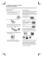
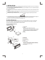
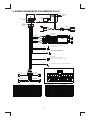
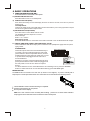
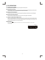
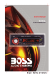
Size: 139 x 216mm
1. BUTTONS LOCATION AND FUNCTIONS
1
8
3
11
PANEL
MONO/
RELEASE STEREO
BUTTON BUTTON
AUTOMATICALLY
STORE / PRESET
SCAN BUTTON
VOLUME
KNOB
AUDIO
BUTTON
MUTE
BUTTON
10
4
2
CD EJECT
BUTTON
PRESET MEMORY BUTTONS (M1~M6)
7
6
12
POWER
BUTTON
DISPLAY
BUTTON
13
5
9
16
LOCAL/
DISTANT
BUTTON
BAND/
LOUDNESS
BUTTON
SCAN
BUTTON
PRESET
EQUALIZER
BUTTON
AUX IN
JACK
SOURCE TUNING UP / DOWN
TRACK UP / DOWN
BUTTON /
BUTTONS
SUB-WOOFER
15
17
14
1
2. HANDLING COMPACT DISCS
MOISTURE CONDENSATION
On a rainy day or in a very damp area, moisture may condense on the lenses inside the unit. Should this
occur, the unit will not operate properly. In such a case, remove the disc and wait for about an hour until
the moisture has evaporated.
NOTES ON CDs
NOTES ON DISCS
1. A dirty or defective disc may cause sound
dropouts while playing. To enjoy optimum
sound, handle the disc as follows.
Handle the disc by its edge. To keep the disc
clean, do not touch the surface (P.1).
If you use the discs explained below, the sticky
residue can cause the CD to stop spinning and
may cause malfunction or ruin your discs.
Do not use second-hand or rental CDs that have a
sticky residue on the surface (for example, from
peeled-off stickers or from ink, or glue leaking
from under the stickers).
There are paste residue.
Ink is sticky (P.5).
****
*******
P. 1
2. Do not stick paper or tape on the disc (P.2).
P. 5
*******
******* *******
Do not use CDs with old labels that are beginning
to peel off.
Stickers that are beginning
to peel away, leaving a
sticky residue (P.6).
P. 6
P. 2
3. Do not expose the discs to direct sunlight or
heat sources such as hot air-ducts, or leave
them in a car parked in direct sunlight where
there can be a considerable rise in
temperature inside the car (P.3).
**************
*******
*******
*******
Do not use your CDs with labels or stickers
attached.
Labels are attached (P.7).
*******
*******
*******
*******
*******
P. 7
Do Not Use Special Shape CDs
Be sure to use round shape CDs only for this
unit and do not use any special shape CDs.
Use of special shape CDs may cause the unit
to malfunction.(P.8).
P. 3
4. Before playing, clean the discs with an
optional cleaning cloth. Wipe each disc from
the center out (P.4).
P. 8
Be sure to use CDs with disc mark
RECORDABLE
REWRITABLE
Only for this unit.
P. 4
5. Do not use solvents such as benzine,
thinner,commercially available cleaners, or
antistatic spray intended for analog discs.
CD-Rs and CD-RWs which have not undergone
finalization processing cannot be played. (For
more information on finalization processing,
refer to the manual for your CD-R/CD-RW
writing software or CD-R/CD-RW recorder.)
Additionally, depending on the recording status,
it may prove impossible to play certain CDs
record on CD-R or CD-RW.
2
3. INSTALLATION
Before finally installing the unit, connect the wiring temporarily and make sure it is all connected up
properly and the unit and system work properly.
Use only the parts included with the unit to ensure proper installation. The use of unauthorized parts
can cause malfunctions.
Consult with your nearest dealer if installation requires the drilling of holes or other modifications of the
vehicle.
Install the unit where it does not get in the driver's way and cannot injure the passenger if there is a
sudden stop, like an emergency stop.
If installation angle exceeds 30° from horizontal, the unit might not give its optimum performance.
30°
Avoid installing the unit where it would be subject to high temperature, such as from direct sunlight, or
from hot air, from heater, or where it would be subject to dust dirt or excessive vibration.
Be sure to remove the front panel before installing the unit.
DIN FRONT/REAR-MOUNT
This unit can be property installed either from “Front” (conventional DIN Front-mount) or “Rear”(DIN
Rear-mount installation, utilizing threaded screw holes at the sides of the unit chassis). For details,
refer to the following illustrated installation methods A and B.
DIN FRONT-MOUNT (Method A)
Installation the unit
1
2
182
53
3
1
6
1.
2.
3.
4.
5.
6.
7
4
2
5
3
1. Dashboard
2. Holder
After inserting the half sleeve into the
dashboard, select the appropriate tab according
to the thickness of the dashboard material and
bend them inwards to secure the holder in
place.
3. Screw
Dashboard
Nut (5mm)
Spring washer
Screw (5x15mm)
Screw
Support Strap
Be sure to use the support strap to secure the
back of the unit in place. The strap can be bent
by hand to the desired angle.
7. Plain washer
3
Removing the unit
a
a. Frame
b. Insert fingers into the groove in the front
of frame and pull out to remove the
frame. (When re-attaching the frame,
point the side with a groove down wards
and attach it.)
c. Insert the levers supplied with the unit
into the grooves at both sides of the unit
as shown in figure until they click. Pulling
the levers makes it possible to remove
the unit from the dashboard.
b
c
Trim Plate Installation:
Push the trim plate against the chassis until it is fitted.
You must do this before you install the front panel, otherwise it can't be attached.
DIN REAR-MOUNT (METHOD B)
Installation using the screw holes on the sides of the unit.
Fastening the unit to the factory radio mounting bracket.
1. Select a position where the screw
holes of the bracket and the screw
holes of the main unit become
aligned (are fitted) and tighten the
screws at 2 places on each side.
2. Screw
3. Factory radio mounting bracket.
4. Dashboard or Console
5. Hook (Remove this part)
2
4
5
3
2
Note: the mounting box, outer trim ring,
and half-sleeve are not used for method
B installation.
5
4
4. DETACHABLE CONTROL PANEL (D.C.P.)
Removing The Detachable Control Panel (D.C.P.).
1. Turn the power off
2. Press the D.C.P. release button
3. Remove the D.C.P.
PANEL RELEASE
BUTTON
Attaching the DCP
2
A
B
1. Attach the panel at the right side first, with
point B on the main unit touching point A on
the D.C.P. (As shown on the digram).
2. Then press the left side of D.C.P. onto the main
unit until a “click” sound is heard.
CAUTION
DO NOT insert the D.C.P from the left side. Doing so may damage it.
The D.C.P can easily be damaged by shocks. After removing it, place it in a protective case and be careful not to drop
it or subject it to strong shocks.
When the release button is pressed and the D.C.P is unlocked, the car's vibrations may cause it to fall. To prevent
damage to the D.C.P, always store it in a protective case after detaching it.
The rear connector that connects the main unit and the D.C.P is an extremely important part. Be careful not to
damage it by pressing on it with fingernails, pens, screwdrivers, etc.
Socket
Note:
If the D.C.P is dirty, wipe off the dirt with soft,
dry cloth only. And use a cotton swab soaked
in isopropyl alcohol to clean the socket on the
back of the D.C.P.
5
5. WIRING DIAGRAM (20 PIN HARNESS PLUG)
ANTENNAJACK
ANTENNAPEXT
ENDERP
CABLE
FUSE
20-PIN
AUDIO/POWER
HARNESS
(See Figure 1)
L-CH
WHITE
YELLOW
RCA-TO-RCA CABLES
(not supplied)
SUB WOOFER
BLUE
AUX IN
R-CH
SUB-WOOFER
WHITE
RED
RCA-TO-RCA CABLES
(not supplied)
WHITE
L-CH
REAR LINE OUT
GREY
R-CH
RED
AMP
WHITE
L-CH
FRONT LINE OUT
BLACK
R-CH
RED
BLUE
Power antenna wire that can also be used
for remote turn on led.
BLACK
Ground Connect to ground terminal or
Clean unpainted metal part of chassis
Memory/Battery
Connect to a constant 12 volt source.
The radio will not work if this wire is not connected.
YELLOW
RED
Accessory/Ignition Connect to existing radio wire or radio fuse.
20-PIN AUDIO/POWER HARNESS
LEFT FRONT
WHITE-BLACK LF-
RIGHT FRONT
GREY-BLACK RF-
WHITE LF+
LEFT REAR
GREEN-BLACK LR
1
2
3
4
5
6
7
8
9
10
11
12
13
14
15
16
17
18
19
20
GREY RF+
RIGHT REAR
VIOLET-BLACK RR-
GREEN LR+
VIOLET RR+
Figure 1
Pin View
PIN
WIRE COLOR
WIRE COLOR
GREY/BLACK
FUNCTION/LABEL
RIGHT FRONT SPEAKER (-)
PIN
1
11
WHITE
2
GREY
RIGHT FRONT SPEAKER (+)
12
WHITE/BLACK
FUNCTION/LABEL
LEFT FRONT SPEAKER (+)
LEFT FRONT SPEAKER (-)
3
VIOLET
RIGHT REAR SPEAKER (+)
13
4
VIOLET/BLACK
RIGHT REAR SPEAKER (-)
14
BLUE
POWER ANTENNA
5
6
15
YELLOW
GREEN
LEFT REAR SPEAKER (+)
16
BLACK
CHASSIS GROUND
7
GREEN/BLACK
LEFT REAR SPEAKER (-)
17
WHITE
LEFT FRONT PRE-AMP LINE OUT
8
RED
IGNITION(ACC)
18
RED
RIGHT FRONT PRE-AMP LINE OUT
9
BLACK
REAR PRE-AMP LINE OUT COMMON
19
BLACK
FRONT PRE-AMP LINE OUT COMMON
RED
RIGHT REAR PRE-AMP LINE OUT
20
WHITE
LEFT REAR PRE-AMP LINE OUT
10
6
BATTERY(+)
6. BASIC OPERATIONS
1) PANEL RELEASE BUTTON (REL)
Press this button to remove the control panel.
12) POWER ON/OFF BUTTON
Press this button to turn on or off the power.
5) DISPLAY BUTTON (DISP)
Press this button briefly, the LCD will display the clock for about 2 seconds, then return to previous
display mode.
Clock Adjustment
Under clock display mode, press DISP button until the LCD flashes, press Tuning Up Button to adjust
hour and Tuning Down Button to adjust minute.
15) SOURCE BUTTON (SOURCE)
Press this button to select Radio and CD modes.
The available selections depends on version:
Radio CD Player
Radio > CD > AUX in
Sub-woofer On/Off
Press SOURCE button for more than 3 seconds to activate or turn off the Sub-woofer output.
17) FRONT (AND REAR PANEL) AUXILIARY INPUT JACKS
This unit features AUX IN line input jacks on both the front (headphone type) and rear (RCA
type) panels.
PLEASE NOTE:
AUX IN JACK IN PANEL
These two inputs cannot be used simultaneously. If
you have a source unit plugged into the rear panel
jack and wish to listen to a portable device (such as
an MP3 player) by using the front panel jack, be sure
to power off the unit plugged into the rear unit to
Left Audio
avoid interference.
Right Audio
Ground
Similarly, if you have a device plugged into the front
panel jack and wish to listen to the unit plugged into
3.5mm Audio In Cable (not included)
the rear panel, be sure to turn off the front panel
device.
To select either the front or rear AUX IN device as a listening source, press the SOURCE
button to select AUX mode. To cancel AUX IN listening, press SOURCE again.
1
2
3
RESET BUTTON
The RESET button is located on the main unit (as shown on the diagram). To press it vertically with a
ballpoint pen or metal object will activate it. The reset button is to be activated for the following reasons:
Initial installation of the unit when all wiring is completed.
All the function buttons do not operate.
Error symbol on the display.
Note: If the unit cannot function normally after reseting, please use a cotton swab soaked in
isopropyl alcohol to clean the socket on the back of the control panel.
7
7. AUDIO OPERATIONS
10) VOLUME KNOB
Turn this knob to adjust desired volume level.
4) AUDIO BUTTON
Press this button to select desired audio function.
ORDER OF FUNCTION:
VOLUME(VOL) -> BASS(BAS) -> TREBLE(TRE) ->BALANCE(BAL) ->FADER(FAD)
While the selected function is displayed, turn Volume Knob to adjust the level within 5 seconds,
otherwise the unit will return to volume adjustment mode.
2) MUTE BUTTON (MUTE)
Press this button to mute the sound. Press it again to resume listening.
16) PRESET EQUALIZER BUTTON (EQ)
Press this button to toggle the following EQ settings:
FLAT->CLASSICS->POP M->ROCK M->DSP OFF
At DSP OFF mode, EQ will be controlled by Bass/Treble setting.
13) BAND/LOUDNESS BUTTON (BAND/LOUD)
Press the Band/Loudness Button for couple of seconds to switch the loudness on or off. When
Loudness is on, display will show 'Loud On' for a few seconds.
8
8. RADIO OPERATIONS
11) AUTO MEMORY STORE/PRESET SCAN BUTTON (AS/PS)
1. PRESET SCAN: Press AS/PS button briefly to enter Preset Scan mode, it will scan all the preset
stations in the memories, you can hear that it will stay on each station for about 5 seconds.
2. AUTO MEMORY STORE: Press AS/PS button for couple of seconds to enter Auto Store mode,
this feature will automatically scan the current band and enter up to 6 strongest stations into the
6 preset memories. To stop Auto Store & Scan, press the AS/PS button again.
7) STATION PRESET BUTTONS (M1-M6)
1. Press these buttons briefly to recall the stored stations in the selected band.
2. Presetting stations manually, Press the BAND button to select the band for the stations to be
preset. Use Tuning Up/Down to tune in the stations to be preset. Press the Preset button at
which you want to store the station for at least 2 second. The preset number will appear on the
display accompanied by a beep, this indicates that the station has been stored into memory.
13) BAND/LOUDNESS BUTTON (BAND/LOUD)
This a dual function button. Press this button shortly to change between BAND FM1, FM2, FM3 or
AM bands. Press this button for couple of seconds to turn Loudness function on or off.
14) TUNING / SEEK UP AND TUNING / SEEK DOWN BUTTONS
1. Press these buttons briefly, and the unit will operate in AUTO SEARCH tuning mode, the radio
will tune up or down to the next station and remain on that station.
2. Press these buttons for more than 2 seconds, operate as MANUAL SEARCH buttons, under this
mode the tuning frequency will advance up or down rapidly when the button is pressed. If the
buttons are not pressed within 3 seconds, they will return to auto search mode.
8) MONO STEREO BUTTON (MO/ST)
When you receive a station,“ST” on the display will be on. Press this button to enter Mono mode.
9) SCAN BUTTON(SCAN)
Press this button, the radio will tune up to search stations, the available stations will blink and stay
on the display for a few seconds.
6) LOCAL/DISTANT BUTTON (LOC)
During station tuning, this button allows you prior to access strong local station only (Local
mode), or to access a wider range of using distant mode (DX). When powered on, DX mode will
be defaulted automatically; Press LOC button briefly to select Local mode and “LOCAL” symbol
on the LCD will light up for a few seconds.
9
9. CD OPERATIONS
M1) PAUSE BUTTON (PAUSE)
Press this button to pause CD play, press again to release pause.
M2) SCAN BUTTON (SCAN)
Press this button, the first 10 seconds of each track will be played sequentially until this button
is pressed again, then normal play will resume at the current track.
M3) REPEAT BUTTON (REPEAT)
Press this button, the current track will be played repeatedly until this button is pressed again.
M4) SHUFFLE BUTTON (SHUFFLE)
Press this button to play all tracks on CD in random. Press again to deactivate it.
14) TRACK UP AND TRACK DOWN BUTTON
Press the Track Up Button to skip to the next track or previous track. Press the Track Down
button during play will return to the beginning of the current track, press it one more time to skip
to previous skip. Press and hold Track Up/Down Button to fast forward or fast reverse. CD
player starts playing when you release the button.
EJECT BUTTON
Press this button to eject the CD from the unit. The receiver will switch to radio mode
automatically.
EJECT BUTTON
10
10.SPECIFICATIONS
CD PLAYER
System
Usable disc
Sampling frequency
No of quantization bits
Frequency
Number of channels
S/N Ratio
Compact disc audio system
Compact disc
44.1KHz
1bit
5-20,000Hz
2 stereo
70dB
RADIO SECTION
FM
Frequency Range
Intermediate Frequency
Usable Sensitivity
Stereo Separation
S/N Ratio
87.5-107.9MHz
10.7 MHz
Better than 15dB at S/N 30 dB
25 dB at 1KHz
50 dB
AM/MW
Frequency Range
Intermediate Frequency
Usable Sensitivity
S/N Ratio
530-1710KHz
450KHz
Better than 45dB
40 dB
GENERAL
Power Supply
Polarity
Speaker impedance
Power Output
DC 11 -14V
Negative Ground
4 ohms
4x 60 Watts
REMARK :
Specifications subject to change without notice.
11
11.TROUBLE SHOOTING
Before going through the check list, check wiring connection. If any of the problems persist after check
list has been made, consult your nearest service dealer.
Symptom
No power
Disc cannot be loaded
or ejected
Cause
Solution
The car ignition is not on.
If the power supply is properly connected
to the car accessory terminal, switch the
ignition key to “ACC”
The fuse is blown.
Replace the fuse.
Presence of CD disc inside
the player.
Remove the disc in the player, then put a
new one.
Inserting the disc in reverse
direction.
Insert the compact disc with the label
facing upward.
Compact disc is extremely
dirty or defective disc.
Clean the disc or try to play a new one.
Temperature inside the car is
too high.
Cool off or until the ambient temperature
returns to normal.
Condensation.
Leave the player off for an hour or so,
then try again.
Volume is in minimum.
Adjust volume to a desired level.
Wiring is not properly
connected.
Check wiring connection.
The operation keys do
not work
The built-in microcomputer is
not operating properly due to
noise.
Press the RESET button.
Front panel is not properly fixed into its
place
Sound skips.
The installation angle is
more than 30 degrees.
Adjust the installation angle to less than
30 degrees.
No sound
The disc is extremely dirty or a Clean the compact disc or try to play a
defective disc.
new one.
The radio does not
work.
The radio station
automatic selection
does not work.
The antenna cable is not
connected.
Insert the antenna cable firmly.
The signals are too weak.
Select a station manually.
ERROR 1
Mechanism Error
Press the reset button if the error code
does not disappear, consult your nearest
service dealer.
ERROR 2
Servo Error
Press the reset button if the error code
does not disappear, consult your nearest
service dealer.
If at any time in the future you should need to dispose of this product please note
that Waste electrical products should not be disposed of with household waste.
Please recycle where facilities exist. Check with your Local Authority or retailer for
recycling advice.(Waste Electrical and Electronic Equipment Directive)
12