1
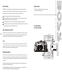
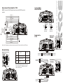
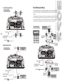
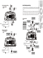
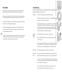
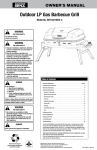
AUDIO SYSTEMS
CONTENTS
Congratulations! 3
A M P L I F I E R S
Specifications
3
Features
4
About Protection Circuitry
5
Amplifiers and 2 Ohm Operation
5
Electrical Wiring
6
Mounting the Amplifier
6
High Input Wiring
7
Mode Switch Settings
8
Low Level Input Wiring
9
Four Channel Amplifier Speaker Wiring 10
GT 1180
Bridged Speaker Wiring with a Four Channel Amplifier 10
Dual Tri-Mode Speaker Wiring with a Four Channel Amplifier 11
Five Channel Amplifier Speaker Wiring 12
Bridged Speaker Wiring with a Five Channel Amplifier 12
Dual Tri-Mode Speaker Wiring with a Five Channel Amplifier 13
Precautions 14
Troubleshooting 15
GT 1380
GT 1480
GT 1580
Congratulations on your purchase of a BOSS Audio Systems GT car audio
amplifier.GT amplifiers are designed and engineered in the USA to the
highest level of quality, and will afford you years of listening enjoyment.
All GT amplifiers utilize fully-regulated MOSFET power supplies, which
ensures that switching response is extremely fast and output power is clean.
Thank you for making BOSS Audio Systems your choice for mobile audio
entertainment.
AUDIO SYSTEMS
A M P L I F I E R S
MODEL
GT 1180
GT 1380
GT 1580
Power Max (2 Ohms)
400W x 4
500W x 4
500W x 4 + 500W x 1
600W x 4
Power RMS (4 Ohms)
100W x 4
150W x 4
80W x 4 + 150W x 1
200W x 4
Bridged Power (4 Ohms)
800W x 2
1000W x 2
1000W x 2 + 500W x 1
1200W x 2
S/N Ratio
103 dB
103 dB
103 dB
103 dB
Low Pass Crossover (Variable)
Continuously-Variable, 45Hz-90Hz
High Pass Crossover
150Hz
150Hz
150Hz
150Hz
Bass Boost (Variable)
0 - +18dB
0 - +18dB
0 - +18dB
0 - +18dB
Tri-mode Operation
YES
YES
YES
YES
Inputs
Line Level and Speaker Level
YES
YES
Remote Subwoofer Level Control
YES
Frequency Response
9Hz - 50KHz (+/- 3dB)
YES
GT1480
THD (at RMS Output)
0.01%
0.01%
0.01%
0.01%
Channnel Separation
90dB
90dB
90dB
90dB
Damping Factor
150+
150+
150+
150+
Fuse Rating
20A x 2
25A x 2
35A x 2
80A x 1
Dimensions (9-5/16"W x 2-3/16"H x ...)
12-1/4" (L)
16-1/2" (L)
19-1/4" (L)
20-1/2" (L)
3
All GT amplifiers feature built-in electronic crossovers.
A M P L I F I E R S
F
E
A
T
Four Channel Amplifiers
GT 1180, GT 1380, GT 1480
4
Four Channel Bridgeable MOSFET Amplifier
Tri-Mode Capable
Heavy-duty Aluminum Alloy Heatsink
Class A-B Operation
Continuously-Variable Low Pass Crossover: 45Hz-90Hz
Bass Boost Switch: 0 to +18dB
Remote Subwoofer Level Control
Continuously-Variable Input Gain Control
High Pass Crossover: 200Hz
Nickel Plated RCA And Speaker Level Inputs
Remote Turn-On/Turn-Off Circuit
MOSFET Pulse Width Modulated Power Supply
2 Ohm Stable Stereo Operation with Output Power Increase
Soft Turn-On Circuit
Thermal and Speaker Short Protection Circuitry
LED Power and Protection Indicators
Five Channel Amplifier
GT 1580
Five Channel Bridgeable MOSFET Amplifier
Tri-Mode Capable
Heavy-duty Aluminum Alloy Heatsink
Class A-B Operation
Continuously-Variable Low Pass Crossover: 45Hz-90Hz
(all channels)
Bass Boost Switch: 0 to +18dB (CH1-CH4)
Variable Bass Boost: 0 to +18dB (CH5)
Remote Subwoofer Level Control
Continuously-Variable Input Gain Control
High Pass Crossover: 200Hz (Channels 1-4)
Nickel Plated RCA And Speaker Level Inputs
Remote Turn-On/Turn-Off Circuit
MOSFET Pulse Width Modulated Power Supply
2 Ohm Stable Stereo Operation with Output Power Increase
Soft Turn-On Circuit
Thermal and Speaker Short Protection Circuitry
LED Power and Protection Indicators
U
R
E
S
AUDIO SYSTEMS
Built-in Crossover
The MonoBlock amplifier (GT1000M) features an continuously-variable low pass and an
+18dB Bass Boost switch.
The 2 Channel, 4 Channel and 5 Channel GT amplifiers feature continuously-variable low
pass crossovers and fixed high pass crossovers. They also all feature a +18 dB Bass Boost switch.
All GT amplifiers have been designed to utilize100% MOSFET power supplies, ensuring
extremely rapid switching response for plenty of clean power.
Protection Circuitry
The amplifier protection circuitry will disable the amplifier if the inputs are overloaded,
short-circuited or if extremely high temperature conditions are detected. When the protection
mode is in operation, the LED indicator on the front panel will be illuminated, indicating
the amplifier has gone into a self-preservation mode.
If you observe that the protection LED is lit, please check the system carefully to determine
what has caused the protection circuit to engage. The amplifier can be reset by turning
the remote power off and then on again. If the amplifier shuts down due to a thermal
overload condition, please allow it to cool down before powering up. If the amplifier shuts
down because of an input overload or short circuit, be sure to repair these conditions before
attempting to power up the amplifier again.
2 Ohm Operation (in stereo mode)
Your GT amplifier was designed to operate effectively at loads as low as 2 Ohms. This
means that you can install four 8 Ohm speakers per channel when using parallel wiring.
Increasing the number of woofers per channel at low frequencies (up to 100Hz) produces an
acoustic coupling effect. This acoustic coupling increases your power output by 3 dB per
speaker.
When operating at 2 Ohms, the amplifiers will increase their output power by approximately
50%. The current draw will also increase by about the same amount. So be sure you have
enough current to run the amplifiers into a 2 Ohm load. If you lack adequate current, your
music reproduction will be distorted.
Please note: The gain control of any car audio amplifier should not be mistaken for a volume
control. It is a sophisticated device, designed to match the output level of your audio source unit
to the input level of the amplifier. Do not adjust this input level to maximum unless your input
level requires it. Ignoring these instructions will result in an input overload to the amplifier, and
excessive audio distortion. It can also cause the protection circuit to engage.
5
High Level Inputs
All BOSS GT series power amplifiers are equipped with easy top access screw terminals. These
terminals are n ickel-plated in order to ensure excellent electrical contact and resist corrosion.
The GT 4-Channel amplifiers utilize a separate connector
for Channels 1/2 and Channels 3/4.
When making electrical connections to the amplifier, please observe the following:
AUDIO SYSTEMS
Electrical Wiring
WARNING: If you use the HIGH LEVEL (speaker) inputs, do not use the LOW LEVEL inputs at the same time.
Use at least 8 gauge or heavier wire for power and ground connections.
Wire the amplifier directly to the car battery. Make sure there is circuit protection (such as a fuse)
on the positive power lead, within 18 inches of the battery.
For the ground connection, use the shortest possible wire to a good chassis ground point.
Wire the Remote connection to the remote turn-on lead of your equalizer or head unit. In some cases
cases this may be the power antenna lead of the head unit.
Four Channel Amplifiers:
GT 1180, GT 1380, GT 1480
Remote Subwoofer Level Control
6
All BOSS GT series power amplifiers are equipped with a dashboard mount remote subwoofer
level control. Run the supplied dashboard remote control from the front panel of your amplifier. By
turning the level knob clockwise, you will increase the output of low frequencies.
CHANNEL 2 (+)
CHANNEL 2 (-)
CHASSIS GROUND
Fuses
CHANNEL 1 (-)
CHANNEL 1 (+)
HEAD UNIT
Fuses protect both the amplifier and the electrical system of your vehicle from faulty conditions. If
you must replace the fuse in your GT amplifier, use a fuse of exactly the same type and rating.
A different type or rating may result in damage or cause a fire.
Mounting the Amplifier
Mark the location for the mounting screw holes by positioning the amplifier where you wish to
install it and use a scribe (or one of the mounting screws) inserted in each mounting hole to mark
the mounting surface. If the mounting surface is carpeted, measure the hole centers and mark with
a felt tip pen.
Drill pilot holes in the mounting surface for the mounting screws and insert the mounting screws
into these holes. Tighten them securely.
Note: Before beginning your installation, be sure to take note of any wires, lines or other devices
in your vehicle which may be located behind any mounting surface .
7
CHANNEL 3 (+)
CHANNEL 3 (-)
CHASSIS GROUND
CHANNEL 4 (-)
CHANNEL 4 (+)
From
HEAD UNIT
SPEAKER
OUTPUTS
WARNING: If you use the HIGH LEVEL (speaker) inputs, do not use the LOW LEVEL inputs at the
same time.
CHANNEL 2 (+)
CHANNEL 2 (-)
CHASSIS GROUND
CHANNEL 1 (-)
CHANNEL 1 (+)
HEAD UNIT
CH1/2
CH1
CH1
From
HEAD UNIT
SPEAKER
OUTPUTS
CH3
CH5-L
CH1
INPUT
CH5
45
45
90
CH3
8
From OUTPUT
of HEAD UNIT
90
90
45
CH4
CH4
INPUT
CH2
INPUT
CH3
INPUT
CH2
CH2
CH3/4
CH4
CH5-R
From OUTPUT
of HEAD UNIT
CH4 CH5
IN IN
INPUT MODE
Fi ve Channel A mpl i f i er:
G T 1580
CHANNEL 3 (+)
CHANNEL 3 (-)
Mode Switch in
4ch Position
CHASSIS GROUND
CHANNEL 4 (-)
CHANNEL 4 (+)
CH1/2
CH1
CH1
CH3
CH5-L
CH5
CH2
Note: Use the 4CH mode when using high level (speaker) inputs and the 5CH mode use with for low level (RCA) inputs.
45
45
90
90
45
90
CH3
CH2
CH3/4
CH4
CH4
CH5-R
CH4 CH5
IN IN
MODE
M ODE
INPUT
Mode Switch Settings
MODE
SWITCH
INPUT
OUTPUT
5CH IN
1CH/2CH/3CH/4CH/5CH
1/2/3/4/5CH
4CH IN
1CH/2CH/3CH/4CH
1/2/3/4/5CH
2CH IN
1CH/2CH
1/2/5CH
From OUTPUT
of HEAD UNIT
CH1 INPUT
CH4 INPUT
CH2 INPUT
CH3 INPUT
CH3 INPUT
From OUTPUT
of HEAD UNIT
Mode Switch in
5ch Position
CH1 INPUT
Y adaptor
When the high level (speaker) inputs are used, or when
there is no input for CH5, the Mode switch should be
placed in the 5CH position.
CH1/2
CH1
CH1
CH3
CH5-L
CH5
CH2
45
45
90
45
CH1/2
CH1
CH1
CH3
CH5-L
90
CH5
CH3
CH2
45
45
CH4
CH2
CH3/4
90
90
45
90
CH3
CH4
CH2
CH3/4
CH4
CH5-R
From OUTPUT
of HEAD UNIT
CH4 CH5
IN IN
CH2 INPUT
MODE
M ODE
INPUT
From OUTPUT
of HEAD UNIT
CH4 INPUT
Y adaptor
CH4
CH5-R
CH4 CH5
IN IN
MODE
M ODE
INPUT
90
AUDIO SYSTEMS
Four Channel Amplifiers:
GT1180, GT 1380, GT148 0
High Level Inputs (5 Channel Amplifier) - GT 1580
9
+
CH1
SPEAKER
+
Four Channel Amplifiers
GT 1180, GT 1380, GT 148 0
CH2
SPEAKER
AUDIO SYSTEMS
Dual Tri-Mode Speaker Wiring
Four Channel Speaker Wiring
Tri-Mode Operational Output is a unique feature which allows a subwoofer to be operated in MONO
mode, while the main speakers are playing STEREO simultaneously on one pair of amplifier output
channels.
To engage the amplifier in this mode, place the Crossover (Subwoofer) switch in the FULL position.
Use a 100V non-poplar capacitor for a high pass crossover and a wire coil inductor to block high
frequencies from the subwoofer, as shown in the figure below. Please review the table below for
inductor and capacitor component values to determine the desired crossover frequencies.
Four Channel Amplifiers
GT 1180, GT 1380, GT 148 0
+
+
To REMOTE TURN-ON
from HEAD UNIT
CH 1
SPEAKER
for 6dB Passive Crossover
CH3
SPEAKER
CH4
SPEAKER
SUBWOOFER
SPEAKER
Component Values
GROUND
10
SUBWOOFER MINIMUM
CH 3
IMPEDANCE 8 OHMS!
+
+
CH 2
SPEAKER
+
LOW PASS FILTER
(INDUCTOR)
To BATTERY
HIGH PASS FILTERS
(CAPACITORS)
Bridged Speaker Wiring
Four Channel Amplifiers
GT 1180, GT 1380, GT 148 0
SPEAKER
IMPEDANCE
4 - 8 OHMS!
LEFT SPEAKER
(SUBWOOFER)
+
SPEAKER IMPEDANCE
4 - 8 OHMS!
GROUND
To REMOTE TURN-ON
from HEAD UNIT
HIGH PASS FILTERS
(CAPACITORS)
To BATTERY
GROUND
To REMOTE TURN-ON
from HEAD UNIT
To BATTERY
CH3
SPEAKER
+
RIGHT SPEAKER
(SUBWOOFER)
SPEAKER IMPEDANCE
4 - 8 OHMS!
+
+
+
LOW PASS FILTER
(INDUCTOR)
SUBWOOFER
CH 4
SPEAKER
SPEAKER IMPEDANCE
4 - 8 OHMS!
SUBWOOFER MINIMUM
IMPEDANCE 8 OHMS!
11
Dual Tri-Mode Speaker Wiring
+
CH2
SPEAKER
+
CH1
SPEAKER
+
Five Channel Amplifier:
GT 1580
AUDIO SYSTEMS
Five Channel Speaker Wiring
CH 5 SPEAKER
(SUBWOOFER)
Tri-Mode Operational Output is a unique feature which allows a subwoofer to be operated in MONO
mode, while the main speakers are playing STEREO simultaneously on one pair of amplifier output
channels.
To engage the amplifier in this mode, place the Crossover (Subwoofer) switch in the FULL position.
Use a 100V non-poplar capacitor for a high pass crossover and a wire coil inductor to block high
frequencies from the subwoofer, as shown in the figure below. Please review the table below for
inductor and capacitor component values to determine the desired crossover frequencies.
SUBWOOFER MINIMUM
IMPEDANCE 8 OHMS!
Five Channel Amplifiers
GT 1580
GROUND
+
12
+
To REMOTE TURN-ON
from HEAD UNIT
To BATTERY
CH4
SPEAKER
SPEAKER IMPEDANCE
4 - 8 OHMS!
Component Values
for 6dB Passive Crossover
CH3
SPEAKER
SUBWOOFER
CH 1
SPEAKER
+
+
CH 2
SPEAKER
+
LOW PASS FILTER
(INDUCTOR)
SPEAKER IMPEDANCE
4 - 8 OHMS!
+
HIGH PASS FILTERS
(CAPACITORS)
Bridged Speaker Wiring
SPEAKER IMPEDANCE
4 - 8 OHMS!
SUBWOOFER MINIMUM
IMPEDANCE 8 OHMS!
BRIDGED
LEFT SPEAKER
+
Five Channel Amplifier:
GT 1580
+
CH 5 SPEAKER
(SUBWOOFER)
CH 5 SPEAKER
(SUBWOOFER)
GROUND
HIGH PASS FILTERS
(CAPACITORS)
To REMOTE TURN-ON
from HEAD UNIT
+
+
CH 3
SPEAKER
CH 4
SPEAKER
To BATTERY
GROUND
To REMOTE TURN-ON
from HEAD UNIT
To BATTERY
SPEAKER IMPEDANCE
4 - 8 OHMS!
+
+
BRIDGED
RIGHT SPEAKER
SPEAKER IMPEDANCE
4 - 8 OHMS!
LOW PASS FILTER
(INDUCTOR)
SUBWOOFER
SUBWOOFER MINIMUM
IMPEDANCE 8 OHMS!
SPEAKER IMPEDANCE
4 - 8 OHMS!
13
Troubleshooting
Before you drill or cut any holes, investigate your car's layout very carefully. Take care
when you work near the gas tank, fuel lines, hydraulic lines and electrical wiring.
Before removing your amplifier, refer to the list below and follow the suggested procedures.
Always test the speakers and their wires first.
No Output
Do not operate the amplifier when it is not mounted. Attach all audio system components
securely within the automobile to prevent damage, especially in case of an accident.
Confirm that the audio signal source (car radio, equalizer, etc.) is connected and
is supplying output signal. To check if the amplifier is supplying signal, unplug
the RCA cables from the signal source (but leave them plugged into the amp).
Gently tap the center pin of each of the disconnected RCA plugs with your finger.
This should produce a noise (feedback) in your speakers.
Before making or breaking power connections in your system, disconnect the vehicle
battery. Confirm that your head unit or other equipment is turned off while connecting
the input jacks and speaker terminals.
If you need to replace the power fuse, replace it only with a fuse identical to that supplied
with the system. Using a fuse of different type or rating may result in damage to your
system which isn't covered by the manufacturer's warranty.
Confirm that all terminal strip connections are secure and tight.
Check both in-line and built-in fuses. Both the "+12V" and the "REMOTE" terminals
must have +12V referenced to chassis ground.
Do not mount this amplifier so that the wire connections are unprotected or in a pinched
condition, or likely to be damaged by nearby objects.
14
AUDIO SYSTEMS
Precautions
Only one
channel
works
Confirm that all speaker strip connections are secure and tight.
Check the BALANCE control on the head unit (or other source) to verify that it
is set to its midpoint.
If you are using the Low Level RCA Inputs, reverse the input plugs at the amplifier
(switches the R with the L). If the channel which is silent switches to other side,
the problem is either in the head unit/other source or the connecting tables.
Weak Output
Readjust the Input Sensitivity Control to better suit the input signal.
Noise in the
Audio
If the noise is a "whine" whose pitch follows the engine speed, confirm that the
amplifier and any other signal sources ( head unit, etc.) are properly grounded.
If the noise is a "clicking" or "popping" noise whose rate follows the engine speed,
this usually means that the vehicle is equipped with resistor spark plugs and wires,
or that the ignition is in need of service.
Check the routing of the speaker and input wires to make sure they are not
adjacent to wires which interconnect lights and other accessories.
15