1
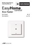
DCN Voting Units en Installation and User Instructions DCN Voting Units LBB 4141/00 and LBB 4141/50 DCN Voting Units Installation and User Instructions en | 2 Important Safeguards About this Manual Prior to installing or operating this product always read the Safety Instructions, which are available as a separate document. Purpose The purpose of the Installation and User Instructions is to provide information required to install and operate a DCN system with voting units LBB 4141/00 and LBB 4141/50. Audience This manual is primarily intended for installers who are responsible for the installation and configuration of a DCN system with voting units LBB 4141/00 and LBB 4141/50. Besides information required installing the system, this manual also contains user instructions. These are intended for the users of the system. Hyperlinks The Installation and User Instructions are available as a digital document in the Adobe Portable Document Format (PDF). All references to pages, figures, tables, etc. in this digital document contain hyperlinks to the referenced location. Bosch Security Systems B.V. | June 2004 | 9922 141 70611 DCN Voting Units Installation and User Instructions Table of contents 1 2 2.1 2.2 2.3 2.4 2.4.1 2.4.2 2.4.3 2.5 2.6 2.6.1 2.6.2 2.6.3 2.6.4 2.6.5 2.7 2.8 2.8.1 2.8.2 2.8.3 2.8.4 2.8.5 2.8.6 2.9 2.9.1 2.9.2 2.9.3 2.9.4 2.10 Introduction................................................................... 4 Voting Units and Accessories ............................. 5 Introduction............................................................... 5 Controls, Connectors and Indicators ................. 5 Voting Button Order ............................................... 5 Mounting ................................................................... 6 Snap Mounting ........................................................ 6 Block Mounting........................................................ 6 De-mounting ............................................................. 7 Connecting ............................................................... 7 Initializing ................................................................... 7 De-initialization of a System.................................. 8 De-Initialization of Individual Voting Units.......... 8 Initialization of Individual Voting Units ................ 8 Replacing a Voting Unit ......................................... 8 Re-installing a Temporary System....................... 8 Commissioning ........................................................ 8 Using .......................................................................... 8 Introduction............................................................... 8 Locating Buttons by Touch................................... 9 Unit Active Indication.............................................. 9 Attendance Registration........................................ 9 Voting Authorization and Access Control ......... 9 Voting......................................................................... 9 Troubleshooting.....................................................10 Fault Indication on a Voting Unit........................10 Address Conflict....................................................10 Disconnect Indication via a PC..........................10 General Trouble Shooting Procedure ..............11 Technical Data .......................................................11 Bosch Security Systems B.V. | June 2004 | 9922 141 70611 en | 3 DCN Voting Units Installation and User Instructions 1 Introduction The LBB 4141/00 and LBB 4141/50 voting units are part of the DCN range. This manual only contains the information specific for installing and using the LBB 4141/00 and LBB 4141/50 voting units. For more detailed information about how to install, design and operate a DCN system with voting units and the related software packages, read the following manuals: • DCN Installation and Operating Manual • LBB 3571 Synoptic Microphone Control Software Manual • LBB 3575 Parliamentary Voting Software Manual • LBB 3576 Multi Voting Software Manual • LBB 3578 Attendance Registration and Access Control Software Manual • LBB 3580 Delegate Database Software Manual • LBB 3584 Video Display Software Manual • LBB 3585 DCN System Installation Software Manual • LBB 3590 DCN Startup Software Manual Bosch Security Systems B.V. | June 2004 | 9922 141 70611 en | 4 DCN Voting Units Installation and User Instructions 2 en | 5 Voting Units and Accessories 5 4 4 2.1 Introduction The voting unit range consist of: • LBB 4141/00 Voting Unit • LBB 4141/50 Chinese Voting Unit • LBB 4125/00 Set of 50 End Caps • LBB 4127/00 Set of 50 Coupling Pieces Figure 2.4 LBB 4127/00 (Set of 50) Coupling Pieces This chapter describes how to install and use these units. 6 7 2.2 Controls, Connectors and Indicators 8 9 1 Figure 2.5 LBB 4141/xx Voting Unit (side view) 2 Figure 2.1 to Figure 2.5: 1 3 2 Figure 2.1 LBB 4141/00 Voting Unit (top view) 3 1 4 5 6 2 7 8 9 3 Unit active indicator – for indication of normal operation and faults Buttons with indicators – for attendance registration, voting and initialization Pimple - for quickly locating the voting buttons by touch, especially for visual impaired Click to fit mechanism – for securing voting units and end caps in coupling pieces and metal plates Screw - for fixation of the coupling piece De-init/init switch – for de-initialization and initialization of the unit Button order jumper – for setting the voting button order for parliamentary voting 1 meter DCN cable with male connector 1 meter DCN cable with female connector Figure 2.2 LBB 4141/50 Voting Unit Chinese (top view) 2.3 Voting Button Order 4 The LBB 4141/00 is delivered with for parliamentary voting the button order: present, no (-), abstain (x) and yes (+). See Figure 2.1. The button order can be changed into: present, yes (+), no (-) and abstain (x). See Figure 2.6. Figure 2.3 LBB 4125/00 (Set of 50) End Caps Bosch Security Systems B.V. | June 2004 | 9922 141 70611 DCN Voting Units Installation and User Instructions en | 6 2.4 Mounting The LBB 4141/00 and LBB 4141/50 voting units can be snap-mounted and block mounted. 2.4.1 Snap Mounting Figure 2.6 Changed Voting Button Order LBB 4141/00 To change the voting button order: 1 Unscrew the front plate of the voting unit. Keep the two screws. 2 Remove the three buttons in the middle of the unit by squeezing the snap fingers of the buttons with a pair of tweezers. 3 Insert the buttons in the correct position. (see Figure 2.6). 4 Fasten the PCB back to the front plate. 5 Set the button order jumper on position 1 (see Figure 2.7). i The snap-mounting method is used to install flushmounting units in panels with a thickness of 2 mm. This method uses the ‘click-to-fit’ mechanism to secure the units in cutouts in tabletops or the armrest of seats. See Figure 2.1 for a close up of the click-to-fit mechanism and Figure 2.9 for the dimensions for snap mounting. Figure 2.8 Click-to-fit mechanism Note Do not touch the electronics, in order to prevent damage by static discharge. . 1 . 2 Figure 2.7 Positions button order jumper. The default position of the button order jumper is: • LBB 4141/00: position 2 • LBB 4141/50: position 1 i Note The voting unit can not be used for audience response voting, multiple choice voting, opinion poll voting and rating, when the button order jumper is set to position 1. Figure 2.9 Dimensions for snap mounting 2.4.2 Block Mounting The block-mounting method is used to install flushmounting units in surroundings of more than 2 mm. This method uses couple pieces (LBB 4127/00) to flush mount the voting units in cutouts in tabletops, metal plates or armrests of seats. The end caps (LBB 4125/00) cover the coupling pieces and complete the attractive design. See Figure 2.10 for the procedure for block mounting a voting unit and Figure 2.11 for the dimensions for block Bosch Security Systems B.V. | June 2004 | 9922 141 70611 DCN Voting Units Installation and User Instructions mounting. In stage 3: fasten the screws of the coupling pieces, in order to fixate the coupling pieces. en | 7 2.4.3 De-mounting Follow the mounting procedure in reverse. Use a spatula to remove the end caps and a screwdriver to unlock the click-to-fit mechanism of the voting unit. > i Note Take care not to damage the furniture while removing the end caps and voting unit. Replace the end caps in case those are damaged. 2.5 Connecting The LBB 4141/00 and LBB 4140/50 voting units can be directly connected to the trunk line in a loopthrough chain (see Figure 2.12). See the DCN Installation and Operating Manual for the system limits and for how to design and install a DCN system. Figure 2.10 Block mounting a voting unit in a table Figure 2.12 Direct loop-through connection i Note An unused output cable must be terminated by an LBB 4118/00 Termination Plug. 2.6 Initializing When all the units in a system have been installed, the system must be initialized and made ready for use once. The initialization procedure enables all DCN units installed to be recognized by the CCU. Recognition is given in the form of an address, allocated by the CCU to each active unit in the system. Figure 2.11 Dimensions for block mounting See chapter 11 of the DCN Installation and Operating Manual for how to initialize and assign seat numbers in a PC-based system. Bosch Security Systems B.V. | June 2004 | 9922 141 70611 DCN Voting Units Installation and User Instructions en | 8 2.6.1 De-initialization of a System Systems, which are powered-up for the first time, are de-initialized. All LEDs of the de-initialized units illuminate. In case some of the units are not in this state, de-initialize these units or de-initialize the system. See chapter 11 of the DCN Installation and Operating Manual for how to de-initialize a system. 2.6.2 De-Initialization of Individual Voting Units To de-initialize an individual unit, press the deinit/init switch shortly (see Figure 2.13). All LEDs of the de-initialized unit illuminate. To de-initialize and initialize an individual unit at the same time, keep the de-init/init switch pressed for a longer time. Figure 2.13 De-Initialization LBB 4141/xx Voting Unit 2.6.3 Initialization of Individual Voting Units To initialize an individual unit, press the button in the middle of the voting unit (see Figure 2.14 and Figure 2.15) or the de-init/init switch (see Figure 2.13). The units LEDs go out. Once the unit is recognized in the system, the unit active indicator illuminates. Repeat this procedure for all active units installed in the system one by one. i Figure 2.15 Initialization LBB 4141/50 2.6.4 Replacing a Voting Unit Press the de-init/init (see Figure 2.13) switch while connecting a replacement unit. The unit will be deinitialized and initialized during connection. Once the unit is recognized in the system, the unit active indicator illuminates. 2.6.5 Re-installing a Temporary System The units hold their addresses when the units are disconnected. It is not necessary to de-initialize the system, in case the same units are reconnected after being stored. In case the units have been used in another system in the meantime, follow the procedures described in order to de-initialize the system and initialize the units. i Note In case the temporary system is a Multi CCU system, reconnect the units to the same CCU as during initialization in order to eliminate address conflicts or de-initialize the system. Note 2.7 Commissioning Initialize the units one by one (and not simultaneously) in order to eliminate address conflicts. To check whether a system with LBB 4141/xx voting units works properly: 1. Start a voting (see paragraph 2.8.6) 2. Register presence and vote yes on all units (see paragraph 2.8.6). See paragraph 2.9 in case a voting unit is not working properly. 3. Check the voting results. If the voting results are incorrect: determine which voting unit causes the wrong results. Correct the position of the voting button order jumper (see paragraph 2.3). 2.8 Using Figure 2.14 Initialization LBB 4141/00 2.8.1 Introduction The LBB 4141/00 voting unit can be used for attendance registration, parliamentary voting, audience response voting, multiple choice voting, opinion poll voting, rating and for/against voting. Bosch Security Systems B.V. | June 2004 | 9922 141 70611 DCN Voting Units Installation and User Instructions en | 9 The LBB 4141/50 Chinese voting unit can be used for attendance registration, parliamentary voting and for/against voting. 2.8.2 Locating Buttons by Touch The pimple beneath the button in the middle of the voting unit allows users, especially visual impaired to quickly locate the voting buttons by touch (see Figure 2.1 and Figure 2.2) Figure 2.18 Presence Registration LBB 4141/00 2.8.3 Unit Active Indication The blue unit active indicator illuminates in normal operation (see Figure 2.16 and Figure 2.17). If the unit active indicator flashes or does not illuminate, see paragraph 2.9.1 for troubleshooting. Figure 2.19 Presence Registration LBB 4141/50 Figure 2.16 Unit Active Indication LBB 4141/00 In case the option “registration at entrance/exit unit” is selected, the voting unit will stay inactive until the delegate assigned to that unit is registered present (e.g. registered with a chip card). 2.8.5 Voting Authorization and Access Control A PC is required for voting authorization and access control. The operator specifies whether individual delegates are allowed to take part in electronic voting and initiates access control. See the manual of LBB 3580 Delegate Database and LBB 3578 Attendance Registration and Access Control. Figure 2.17 Unit Active Indication LBB 4141/50 2.8.4 Attendance Registration A PC is required for attendance registration. The operator initiates attendance registration. See the manual of LBB 3578 Attendance Registration and Access Control. The LED above the present button flashes, in case the option “registration at seat by present key” is selected (see Figure 2.18 and Figure 2.19). To register presence, presses the present button. The LED goes out. In case access control is enabled for voting, the voting unit will stay inactive if the delegate assigned to that unit has no voting authorization. 2.8.6 Voting The user interaction of the voting units in a standalone system is described in this paragraph. See the manuals of LBB 3575 Parliamentary Voting and LBB 3576 Multi Voting for other options. The chairman initiates the voting session. The LED above the present button starts to flash (see Figure 2.18 and Figure 2.19). To register presence, press the present button. The LED above the present button goes out and the LEDs above the yes (green, +), no (red, -) and abstain (yellow, x) button start to flash (see Figure 2.20 and Figure 2.21). Bosch Security Systems B.V. | June 2004 | 9922 141 70611 DCN Voting Units Installation and User Instructions en | 10 If the unit active indicator does not illuminate: 1. Check whether the unit is connected. 2. Follow the general trouble shooting procedure (see paragraph 2.9.4). Figure 2.20 Parliamentary Voting LBB 4141/00 2.9.2 Address Conflict In some cases the voting unit cannot detect an address conflict. Symptoms of a voting unit with an address conflict: • The number of units detected by LBB 3585 System Installation software is less than the actual number of units installed. • The voting unit does not respond. • The voting unit responds to key presses on another unit. In case a voting unit is not responding correctly: 1. De-initialize and initialize the unit (see paragraphs 2.6.2 and 2.6.3). 2. Follow the general trouble shooting procedure (see paragraph 2.9.4), in case the problem is not solved. Figure 2.21 Parliamentary Voting LBB 4141/50 To vote, press the yes, no or abstain button. The LED above the pressed button illuminates. To change your vote, press one of the other buttons. When the chairman holds the voting, the voting unit becomes inactive and the LEDs go out. When the chairman restarts the voting, the LEDs return to their previous state. 2.9.3 Disconnect Indication via a PC The LBB 3571 Synoptic Microphone Control Software displays which unit is disconnected (see Figure 2.22). The voting unit is represented as if it is a delegate unit. Once the chairman stops the voting session, the voting session is finished and the LEDs go out. 2.9 Troubleshooting 2.9.1 Fault Indication on a Voting Unit The unit active indicator flashes in case the unit detects a communication fault. If the unit active indicator flashes: 1. Press the button in the middle of the voting unit shortly (see Figure 2.14 and Figure 2.15). In case all LEDs of the unit illuminate, the unit is deinitialized and the problem was caused by an address conflict. Press the button in the middle of the voting unit in order to initialize the voting unit. Once the unit is recognized in the system, the unit active indicator illuminates and the address conflict is solved. 2. Follow the general trouble shooting procedure (see paragraph 2.9.4), in case the problem is not solved. Figure 2.22 Disconnects via LBB 3571 software Additionally, the LBB 3590 Start Up software can be configured for logging and for displaying pop-up warnings for connects and disconnects in the system (see Figure 2.23). The voting unit is represented as if it is a delegate unit. Bosch Security Systems B.V. | June 2004 | 9922 141 70611 DCN Voting Units Installation and User Instructions Figure 2.23 Pop up warning via LBB 3590 software In case a disconnect is detected: check the fault indication on the related unit and follow the instructions of paragraph 2.9.1. If, however, the unit active indicator of the associated unit illuminates: 1. Check whether the fault is caused by an address conflict. See paragraph 2.9.2. 2. Follow the general trouble shooting procedure (see paragraph 2.9.4), in case the problem is not solved 2.9.4 General Trouble Shooting Procedure General trouble shooting procedure: 1. Check whether the trunk line is terminated. If not so, terminate the trunk line with an LBB 4118/00 Termination Plug. 2. Check if the trunk cable connectors are well fitted in their sockets. 3. Check the cabling/cable quality. Replace suspected cables and check whether the problem still occurs. 4. Check the system design. See the DCN Installation and Operating Manual. 5. Replace the unit. See paragraph 2.6.4. Check whether the problem is solved. 2.10 Technical Data LBB 4141/00 and LBB 4141/50 Voting Units Electrical Power consumption 0.8 PCF Mechanical Dimensions (H x W x D) 40 x 100 x 82 mm Weight 250 g Color Silver (RAL 9022) Bosch Security Systems B.V. | June 2004 | 9922 141 70611 en | 11 For more information please visit www.boschsecuritysystems.com © 2004 Bosch Security Systems B.V. Data subject to change without notice June 2004 | 9922 141 70611