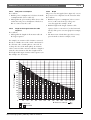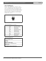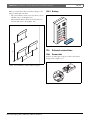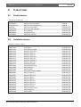
1
DCN Wireless
Installation and User Instructions
en
Wireless discussion system
DCN Wireless | Installation and User Instructions | Important Safeguards
Important Safeguards
Before you install or operate the DCN Wireless digital
congress network, you must read the Important Safety
Instructions. The Important Safety Instructions are
supplied together with the central control unit.
Bosch Security Systems | 2007-02 | 9922 141 70691 en
en | 3
DCN Wireless | Installation and User Instructions | Disclaimers
Disclaimers
CobraNet is a trademark of Peak Audio — a division of
Cirrus Logic, Inc. — in the United States and/or other
countries.
Bosch Security Systems | 2007-02 | 9922 141 70691 en
en | 4
DCN Wireless | Installation and User Instructions | About this manual
en | 5
About this manual
Signs
Function
The Installation and User Instructions shows each
admonition with a sign. The sign shows the effect if you
do not obey the instruction.
The Installation and User Instructions gives the
installers and the operators the necessary data to install,
configure and operate a basic DCN Wireless Discussion
System.
Admonition
General sign for cautions and warnings.
When you want to make a more advanced DCN
Wireless Discussion System, you also need information
from the DCN Next Generation Installation and User
Instructions.
Admonition
Risk of electric shock.
The product index (refer to appendix B) tells you where
you can find more data about devices that can be
connected to DCN Wireless.
Digital version
The Installation and User Instructions is available as a
digital file (Portable Document File, PDF).
When the PDF refers you to a location that contains
more data, you can click the text to go there. The text
contains hyperlinks.
Admonitions and notes
The Installation and User Instructions uses admonitions
and notes. The admonition gives the effect if you do not
obey the instructions. These are the types:
• Caution
If you do not obey the caution, you can cause
damage to the equipment.
• Warning
If you do not obey the warning, you can cause
personal injury or death.
Bosch Security Systems | 2007-02 | 9922 141 70691 en
Admonition
Risk of electro-static discharges (refer to the
section ’Electro-static discharges’).
The sign that is shown along with a note gives more
data about the note itself.
Note
General sign for notes.
Note
Refer to another information source.
DCN Wireless | Installation and User Instructions | About this manual
en | 6
Electro-static discharges
Conversion tables
Electro-static discharges can damage electric
components. You must take measures to prevent
electro-static discharges when you touch PCBs (refer to
figure 1).
Length, mass and temperature are in SI units. Refer to
the data below to change SI units to imperial units.
1
2
3
4
5
table 2: Conversion of units of length
1 in =
25.4 mm
1 mm =
1 in =
2.54 cm
1 cm =
1 ft =
0.3048 m
1m=
1 mi =
1.609 km
1 km =
0.03937 in
0.3937 in
3.281 ft
0.622 mi
table 3: Conversion of units of mass
1 lb =
0.4536 kg
1 kg =
2.2046 lb
table 4: Conversion of units of pressure
1 psi =
68.95 hPa
1 hPa =
0.0145 psi
Note
1 hPa = 1 mbar.
12 11
10
9
8
7
6
figure 1: ESD prevention
table 1: ESD prevention
No.
Description
1
Safety isolating transformer
2
Distribution supply box
3
Conductive compartment trays
4
Electro-static voltage sensor
5
Cotton overall
6
Conductive floor mat
7
Conductive boots/heel grounding protectors
8
Conductive stool
9
Strap (resistance 0.5 to 1.0 MΩ)
10
Common reference point
11
Conductive bench top
12
Supply ground
Bosch Security Systems | 2007-02 | 9922 141 70691 en
table 5: Conversion of units of temperature
9
°F = --- ⋅ °C + 32
5
5
°C = --- ⋅ ( °F – 32 )
9
DCN Wireless | Installation and User Instructions | Table of Contents
en | 7
Table of Contents
Important Safeguards ..................................................................................................................................................3
Disclaimers ......................................................................................................................................................................4
About this manual .........................................................................................................................................................5
Table of Contents ..........................................................................................................................................................7
Section 1 - System Design and Planning............................................................................................................. 11
1. Wireless network design ........................................................................................................................................................... 12
1.1 Introduction ............................................................................................................................................................................ 12
1.2 Limits ....................................................................................................................................................................................... 12
1.3 Frequency band .................................................................................................................................................................... 12
2. DCN design .................................................................................................................................................................................. 14
2.1 Introduction ............................................................................................................................................................................ 14
2.2 Calculation tool ..................................................................................................................................................................... 14
2.3 Concepts ............................................................................................................................................................................... 14
2.4 Limits ....................................................................................................................................................................................... 14
2.5 Control capacity ................................................................................................................................................................... 15
2.6 Power capacity ..................................................................................................................................................................... 15
2.7 Cable lengths ........................................................................................................................................................................ 17
2.8 Examples ................................................................................................................................................................................ 19
2.9 Interpretation devices .......................................................................................................................................................... 21
3. Optical network design .............................................................................................................................................................. 22
3.1 Introduction ............................................................................................................................................................................ 22
3.2 Calculation tool ..................................................................................................................................................................... 22
3.3 Limits ....................................................................................................................................................................................... 22
3.4 Control capacity ................................................................................................................................................................... 22
3.5 Power capacity ..................................................................................................................................................................... 22
3.6 Cabling ................................................................................................................................................................................... 23
3.7 Example layouts .................................................................................................................................................................... 25
4. Camera control ............................................................................................................................................................................. 28
4.1 Introduction ............................................................................................................................................................................ 28
4.2 Scenarios ............................................................................................................................................................................... 28
5. Infra-red wireless language distribution .................................................................................................................................. 28
6. CobraNet ....................................................................................................................................................................................... 29
7. User set-up .................................................................................................................................................................................... 29
7.1 Public areas and walkways ................................................................................................................................................ 29
7.2 Headphones/headsets ........................................................................................................................................................ 29
7.3 Speaking distance ............................................................................................................................................................... 29
7.4 Interpreter booths ................................................................................................................................................................. 29
8. Device set-up ................................................................................................................................................................................ 30
8.1 General ................................................................................................................................................................................... 30
8.2 Cables ..................................................................................................................................................................................... 30
8.3 Temperature .......................................................................................................................................................................... 30
8.4 Ventilation .............................................................................................................................................................................. 30
8.5 Cleaning ................................................................................................................................................................................. 30
8.6 Storage ................................................................................................................................................................................... 30
8.7 Acoustic feedback ............................................................................................................................................................... 31
Bosch Security Systems | 2007-02 | 9922 141 70691 en
DCN Wireless | Installation and User Instructions | Table of Contents
en | 8
9. Technical data .............................................................................................................................................................................. 32
9.1 System electrical and electro-acoustic characteristics ............................................................................................... 32
9.2 Environmental conditions ................................................................................................................................................... 33
9.3 Safety ...................................................................................................................................................................................... 33
9.4 Electro-magnetic compatibility .......................................................................................................................................... 34
9.5 Wireless devices .................................................................................................................................................................. 34
9.6 Miscellaneous ....................................................................................................................................................................... 35
Section 2 - Central Devices ...................................................................................................................................... 37
10. DCN-WCCU Wireless Central Control Unit ......................................................................................................................... 38
10.1 Introduction ............................................................................................................................................................................ 38
10.2 Controls, connectors and indicators ............................................................................................................................... 38
10.3 Internal settings .................................................................................................................................................................... 39
10.4 Installation .............................................................................................................................................................................. 43
10.5 External connections ........................................................................................................................................................... 43
10.6 Configuration menu ............................................................................................................................................................. 49
11. DCN-WAP Wireless Access Point ......................................................................................................................................... 60
11.1 Introduction ............................................................................................................................................................................ 60
11.2 Firmware ................................................................................................................................................................................. 60
11.3 Controls, connectors and indicators ............................................................................................................................... 60
11.4 Installation .............................................................................................................................................................................. 61
11.5 External connections ........................................................................................................................................................... 63
11.6 Configuration ......................................................................................................................................................................... 63
11.7 Operation ............................................................................................................................................................................... 65
12. System configuration .................................................................................................................................................................. 67
12.1 Introduction ............................................................................................................................................................................ 67
12.2 Initialization ............................................................................................................................................................................. 67
12.3 Wireless modes .................................................................................................................................................................... 68
12.4 Microphone modes .............................................................................................................................................................. 69
12.5 Repetition rate ....................................................................................................................................................................... 70
12.6 Audio routing modes ........................................................................................................................................................... 70
12.7 Attention chimes ................................................................................................................................................................... 72
12.8 Erase requests-to-speak and speakers ........................................................................................................................... 72
12.9 Floor distribution ................................................................................................................................................................... 72
12.10 Intercom .................................................................................................................................................................................. 73
13. System operation ......................................................................................................................................................................... 74
13.1 Start the system .................................................................................................................................................................... 74
13.2 Stop the system .................................................................................................................................................................... 74
Section 3 - Contribution Devices............................................................................................................................ 75
14. DCN-WDU Wireless Discussion Units .................................................................................................................................. 76
14.1 Introduction ............................................................................................................................................................................ 76
14.2 Controls, connectors and indicators ............................................................................................................................... 76
14.3 Internal settings .................................................................................................................................................................... 79
14.4 Modes ..................................................................................................................................................................................... 81
14.5 Installation .............................................................................................................................................................................. 83
14.6 Subscription .......................................................................................................................................................................... 85
14.7 External connections ........................................................................................................................................................... 86
14.8 Operation ............................................................................................................................................................................... 87
Bosch Security Systems | 2007-02 | 9922 141 70691 en
DCN Wireless | Installation and User Instructions | Table of Contents
en | 9
15. DCN-MICL, DCN-MICS Pluggable Microphones ................................................................................................................ 89
15.1 Introduction ............................................................................................................................................................................ 89
15.2 Controls, connectors and indicators ............................................................................................................................... 89
15.3 External connections ........................................................................................................................................................... 90
15.4 Operation ............................................................................................................................................................................... 90
16. DCN-WLIION Battery Pack ...................................................................................................................................................... 91
16.1 Introduction ............................................................................................................................................................................ 91
16.2 Safety ...................................................................................................................................................................................... 91
16.3 Controls, connectors and indicators ............................................................................................................................... 92
16.4 Installation .............................................................................................................................................................................. 92
16.5 Operation ............................................................................................................................................................................... 92
17. DCN-WCH05 Battery Charger ................................................................................................................................................ 93
17.1 Introduction ............................................................................................................................................................................ 93
17.2 Controls, connectors and indicators ............................................................................................................................... 93
17.3 Installation .............................................................................................................................................................................. 94
17.4 External connections ........................................................................................................................................................... 95
17.5 Operation ............................................................................................................................................................................... 96
18. DCN-WPS Power Supply Adapter ......................................................................................................................................... 97
18.1 Introduction ............................................................................................................................................................................ 97
18.2 Installation .............................................................................................................................................................................. 97
18.3 External connections ........................................................................................................................................................... 97
19. DCN-DDI Dual Delegate Interface .......................................................................................................................................... 98
19.1 Introduction ............................................................................................................................................................................ 98
19.2 Controls, connectors and indicators ............................................................................................................................... 98
19.3 Internal settings .................................................................................................................................................................... 99
19.4 Configuration ......................................................................................................................................................................... 99
19.5 Installation ............................................................................................................................................................................101
19.6 External connections .........................................................................................................................................................101
20. DCN-WFCD10 Flight Case for Wireless Discussion Units ............................................................................................103
21. DCN-WFCCU Flight Case for DCN-WCCU and DCN-WAP ........................................................................................103
Section 4 - Appendices ........................................................................................................................................... 105
A Audio levels .................................................................................................................................................................................106
B Product index ..............................................................................................................................................................................108
C Statements for FCC & Industry Canada ..............................................................................................................................110
D Declarations ................................................................................................................................................................................111
Bosch Security Systems | 2007-02 | 9922 141 70691 en
DCN Wireless | Installation and User Instructions | Table of Contents
Intentionally left blank.
Bosch Security Systems | 2007-02 | 9922 141 70691 en
en | 10
DCN Wireless | Installation and User Instructions | System Design and Planning
Section 1 - System Design and Planning
Bosch Security Systems | 2007-02 | 9922 141 70691 en
en | 11
DCN Wireless | Installation and User Instructions | System Design and Planning
1
1.1
Wireless network design
Introduction
The DCN Wireless has three parts: the wireless
network, the DCN and the optical network. This
chapter tells how to design the wireless network.
1.2
1.3
Frequency band
1.3.1
802.11g specification
en | 12
The wireless network is based on the 802.11g
specification for WiFi technology. Devices that comply
to the 802.11g specification operate in frequency bands
between 2.4000 and 2.4835 GHz.
Limits
Limit 1: Control capacity
The maximum number of devices in the wireless
network that the central control unit can control is 150.
Limit 2: Coverage area
For a good operation of the wireless part, all wireless
discussion units need to be in range of the wireless
access point. The wireless access point has a typical
maximum coverage area of 30 m by 30 m. To
determine the exact coverage area the coverage test kit
can be used.
Note
You can change the power value of the wireless
access point (refer to section 11.6.4).
Limit 3: Frequency
The wireless network must operate in a different
frequency band than adjacent wireless computer
networks (refer to section 1.3).
Note
Although the system operates on frequencies
which are license free world wide, you must be
aware of country specific limitations and follow
them.
1.3.2
Wireless computer networks
Wireless computer networks are also based on the
802.11g specification for WiFi technology. In the
wireless computer networks, 13 overlapping channels
are available (refer to figure 1.1).
1.3.3
Carriers
In the wireless network of DCN Wireless, three
non-overlapping wireless carriers are available (refer to
figure 1.2).
1.3.4
Interference
The wireless network of DCN Wireless can cause
interference on wireless computer networks. You must
make sure the DCN wireless carrier does not overlap
the WLAN channel.
1.3.5
Example
Refer to figure 1.3. In the example, the WLAN channel
is 3. WLAN channel 3 overlaps DCN wireless carriers 0
and 1. Therefore, use DCN wireless carrier 2.
Bosch Security Systems | 2007-02 | 9922 141 70691 en
2.472
2.484
GHz
2.422
2.427
2.432
2.437
2.442
2.447
2.452
2.457
2.462
2.467
2.472
2.484
GHz
3
4
5
6
7
8
figure 1.3: Example of interference
Bosch Security Systems | 2007-02 | 9922 141 70691 en
9
10
11
12
13
1
2.467
1
2.462
2.457
2.452
2.447
0
2.442
2.437
2.432
2.427
2.422
2.417
2.417
2.412
2.400
GHz
2
0
2.412
figure 1.2: DCN wireless carriers
1
2.400
GHz
2.422
2.427
2.432
2.437
2.442
2.447
2.452
2.457
2.462
3
4
5
6
7
8
9
10
11
13
2.484
GHz
2.472
2.467
2.417
2
12
2.412
1
2.400
GHz
DCN Wireless | Installation and User Instructions | System Design and Planning
en | 13
figure 1.1: WLAN channels
2
2
DCN Wireless | Installation and User Instructions | System Design and Planning
2
DCN design
2.4
en | 14
Limits
Make sure that these limits are not exceeded when you
design the DCN:
2.1
Introduction
The DCN Wireless has three parts: the wireless
network, the DCN and the optical network. This
chapter tells how to design the DCN.
2.2
Calculation tool
The calculation tool makes the planning and design of
the DCN easier. You can find the calculation tool on the
CD-ROM that is supplied with your system.
2.3
Concepts
2.3.1
Introduction
This section gives necessary data to understand the
limitations in section 2.4.
2.3.2
Trunk and tap-off sockets
The DCN uses two types of socket:
• DCN trunk sockets
Use the DCN trunk sockets to make a loop-through
in the trunk of the DCN.
• DCN tap-off sockets
Use the DCN tap-off sockets to make more branches
in the DCN. A DCN tap-off socket always
regenerates the digital DCN signal.
2.3.3
Cables
Many devices used in the DCN have a 2 m cable. If
necessary the extension cable (LBB4116) can extend the
device cables.
Bosch Security Systems | 2007-02 | 9922 141 70691 en
Limit 1: Control capacity
The maximum number of active devices that the central
control unit can control is 95:
• Max. 93x DCN-IDESK
• Max. 2x DCN-DDI:
• 1x with intercom handset
• 1x with ambient microphone
The number of passive devices is without limit (refer to
section 2.5).
Limit 2: Power capacity
• The maximum power that one DCN socket of the
central control unit can supply is 65 W.
• The total power that the DCN sockets of the central
control unit can supply is 130 W.
• The maximum power that one DCN socket of the
extension power supply can supply is 85 W
• The total power that the DCN sockets of the
extension power supply can supply is 255 W.
Refer to section 2.6.
Limit 3: Loop-throughs
The maximum number of loop-throughs in succession is
50. If there are more than 50 loop-throughs, the signal
must be regenerated with a trunk splitter (LBB4114/00).
Limit 4: Tap-off connections
The maximum number of tap-off connections in
succession between the central control unit and the last
tap-off in a branch is four. If there are more than four
tap-off connections in succession, the system does not
operate correctly.
DCN Wireless | Installation and User Instructions | System Design and Planning
Limit 5: Cable lengths
Refer to section 2.7:
• With regenerative tap-offs, the maximum cable
length is 250 m from the central control unit to the
furthest device in any branch of the DCN.
• The maximum cable length from the central control
unit to the first regenerative tap-off is 100 m.
• The maximum length of the cable between
regenerative tap-offs is 100 m.
• Open-ended cables can cause an incorrect operation
of the system.
Note
The total cable length includes the 2 m long
device cables.
2.5
Control capacity
2.5.1
Active devices
en | 15
Active devices are devices that can:
• Receive data from the central control unit.
• Transmit data to the central control unit.
Note
Active devices must have an address (refer to
section 12.2).
2.5.2
Passive devices
Passive devices can only receive data from the central
control unit.
2.5.3
Overview
The table shows the active and passive devices in the
DCN.
table 2.1: Active and passive devices
Device
Type
DCN-DDB
Passive/Active
DCN-DDI
Active
DCN-FCS
Passive
DCN-IDESK
Active
2.6
Power capacity
2.6.1
Introduction
Each device uses power and most devices do not have
an independent power supply.
2.6.2
Power consumption
The table shows the power each device in the DCN
uses.
table 2.2: Power consumption
Device
Watt
DCN-DDB
2.0
DCN-DDI
4.5
DCN-FCS
0.9
DCN-IDESK
3.6
Bosch Security Systems | 2007-02 | 9922 141 70691 en
DCN Wireless | Installation and User Instructions | System Design and Planning
2.6.3
Power supplies
2.6.3.3
2.6.3.1 Introduction
The devices that supply power to the DCN are the
central control unit and the extension power supply
(refer to figure 2.1 and figure 2.2). The power that the
central control unit supplies includes the power that the
optical network uses.
2.6.3.2
en | 16
DCN-EPS
DCN-EPS
Trunk
In
e
Tap-off
Out
Out
Out
DCN-WCCU
P < 85 W
DCN-WCCU
RS 232
Port 1
RS 232
Port 2
DCN-EPS
Mains
Network
Audio In 1
Audio Out 1
Audio In 2
Audio Out 2
Trunk
1
2
1
2
Trunk
230
Fault
OK
Tap-off
Fault
115: 100-120V
230: 220-240V
50-60Hz
50-60Hz
T2.5A 250V
T2A H 250V
In
P < 65 W
Out
Out
Out
P < 255 W
DCN-WCCU
RS 232
Port 1
RS 232
Port 2
Mains
Network
Audio In 1
Audio Out 1
Audio In 2
Audio Out 2
Trunk
1
2
1
2
230
Fault
OK
Fault
115: 100-120V
230: 220-240V
50-60Hz
50-60Hz
T2.5A 250V
T2A H 250V
figure 2.2: DCN power supply: DCN-EPS
P < 130 W
Note
If the power is higher than shown in figure 2.2,
an overload situation occurs (refer to section
2.6.4).
DCN-WCCU
RS 232
Port 1
RS 232
Port 2
Mains
Network
Audio In 1
Audio Out 1
Audio In 2
Audio Out 2
Trunk
1
2
1
2
230
Fault
OK
Fault
115: 100-120V
230: 220-240V
50-60Hz
50-60Hz
T2.5A 250V
T2A H 250V
P < 130 W
figure 2.1: DCN power supply: DCN-WCCU
Note
If the power is higher than shown in figure 2.1,
an overload situation occurs (refer to section
2.6.4).
Bosch Security Systems | 2007-02 | 9922 141 70691 en
DCN Wireless | Installation and User Instructions | System Design and Planning
2.6.4
Overload indication
Each DCN socket of the central control unit and
extension power supply has a red LED that comes on to
show that there is a power overload. An overload occurs
when:
• The necessary power for the devices is greater than
that is supplied.
• A short-circuit occurs.
2.7
Cable lengths
2.7.1
Maximum length
en | 17
The cable length between the central control unit and
the furthest device from the central control unit must
not be more than 250 m. The cable length includes the
device cable and extension cables.
2.7.2
To first regenerative tap-off
When an overload occurs, the sockets are deactivated
and the connected devices do not operate. The socket
checks every 8 seconds (DCN-WCCU) or 30 seconds
(DCN-EPS) for power overloads.
The total cable length between the central control unit
and the first regenerative tap-off socket must not be
more than 100 m. This includes the device cables and
extension cables.
2.6.5
2.7.3
Extension cables
Extension cables (LBB4116) have a direct effect on the
available power. The longer an extension cable, the less
power is available to drive the connected devices. You
must chose the length of the extension cables carefully
(refer to section 2.7.5).
Between regenerative tap-offs
The total cable length between two regenerative tap-off
sockets must not be more than 100 m. This includes the
device cables and extension cables.
2.7.4
Open-ended DCN cables
‘Open-ended’ DCN cables are DCN cables of which the
socket is not connected to a device in the DCN.
‘Open-ended’ cables can cause an incorrect operation of
the system. You can ‘close’ the extension cable with a
termination plug (refer to the DCN Next Generation
Installation and User Instructions). When the
‘open-ended’ cable is connected to a termination plug,
the system operates correctly.
2.7.5
Power correction
2.7.5.1
Introduction
The necessary power from a DCN socket of the central
control unit and the extension power supply is affected
by:
• The type and number of connected devices.
• The lengths of the connected extension cables.
The power correction graph (refer to figure 2.3) corrects
the power level to compensate for the extension cables.
2.7.5.2
Calculation
To find the correction for each DCN socket of the
central control unit and the extension power supply
with the graph, you must first calculate:
• The total power consumption of the devices that are
connected to the socket. Refer to section 2.7.5.3.
• The length of the longest extension cable sequence.
Refer to section 2.7.5.4.
Bosch Security Systems | 2007-02 | 9922 141 70691 en
DCN Wireless | Installation and User Instructions | System Design and Planning
en | 18
2.7.5.5
Graph
The power correction graph (refer to figure 2.3) corrects
the power level to compensate for the extension cables.
Do as follows:
1 Find the total power consumption (refer to section
2.7.5.3) on the vertical axis (Y) of the power
correction graph. For example, 40 W.
2 Find the length of the longest extension cable
sequence (refer to section 2.7.5.4) on the horizontal
axis (X) of the power correction graph. For example,
60 m.
3 The intersection of both values gives the necessary
power from the socket. For example, 53 W.
2.7.5.3
Total power consumption
Do as follows:
1 Find the power consumption of each device from the
consumption table (refer to table 2.2).
2 Add together the power used by all the devices. The
result is the total power consumption of the devices
that are connected to the socket.
2.7.5.4
Length of the longest extension cable
sequence
Do as follows:
1 Add together the lengths of all extension cables in
the longest sequence.
For example, an extension cable of 20 m is connected
directly to a DCN socket of the central control unit. To
the extension cable, a trunk splitter is connected. To
each tap-off socket of the trunk splitter, an extension
cable is connected. One extension cable has a length of
10 m, the other extension cable has a length of 40 m.
The length of the longest extension cable sequence is, in
this example: 20 + 40 = 60 m.
85
Y: Power (Watt)
80
75
70
65
60
55
50
45
40
35
30
25
20
15
10
5
81
76
70
65
60
54
49
43
38
32
27
21
16
11
6
0
20
84
78
72
66
60
54
48
42
36
30
24
18
12
6
40
80
73
66
60
53
46
40
33
26
20
13
6
82
75
67
60
52
45
37
30
22
15
7
85
77
68
60
51
42
34
25
17
8
83
73
64
80
70
55
46
36
27
18
9
60
50
40
30
20
10
60
80
100
120
140
DCN-WCCU
+
DCN-EPS
figure 2.3: Power correction graph
Bosch Security Systems | 2007-02 | 9922 141 70691 en
76
65
84
72
54
43
32
21
11
60
48
36
24
12
160
180
80
66
53
40
26
13
200
75
60
45
30
15
220
X: Extension cable (m)
85
68 73
51 55
34 36
17 18
240 250
DCN Wireless | Installation and User Instructions | System Design and Planning
2.8
Examples
2.8.1
Cable lengths
en | 19
DCN-WCCU
Legend
R Regenerative tap-off
P Power overload
RS 232
Port 1
RS 232
Port 2
Mains
Network
Audio In 1
Audio Out 1
Audio In 2
Trunk
1
2
1
2
Audio Out 2
230
Fault
NC C C NO
48V
115: 100-120V
230: 220-240V
48V
Trunk
T2.5A 250V
T2A H 250V
2m
DCN-EPS
In
50-60Hz
50-60Hz
Tap-off
Out
Out
Out
Trunk
100 m
LBB4114/00
LBB4114/00
100 m
R
R
LBB4114/00
LBB4114/00
100 m
100 m
R
R
240 m
240 m
LBB4114/00
LBB4114/00
P
250 m (max)
250 m (max)
P
2m
5 x 2 m = 10 m
5 x 2 m = 10 m
figure 2.4: Example with cable lengths
Point I
The maximum available power with 240 m of extension
cables is 19 W (refer to figure 2.3). Because the first and
second trunk splitter use 2.6 W, the available power at
point I is 19 - 2.6 = 16.4 W.
Bosch Security Systems | 2007-02 | 9922 141 70691 en
Point II
The maximum available power with 240 m of extension
cable is 25 W (refer to figure 2.3). Because the first and
second trunk splitter use 2.6 W, the available power at
point II is 25 - 2.6 = 22.4 W.
DCN Wireless | Installation and User Instructions | System Design and Planning
2.8.2
en | 20
Power correction
DCN-WCCU
RS 232
Port 1
RS 232
Port 2
Mains
Network
Audio In 1
Audio Out 1
Trunk
1
2
48V
48V
1
2
Audio In 2
Audio Out 2
230
Fault
NC C C NO
115: 100-120V
230: 220-240V
50 m
50-60Hz
50-60Hz
T2.5A 250V
T2A H 250V
20 m
3
3
LBB4114/00
2
4
LBB4114/00
2
10 m
LBB4114/00
2
2
4
LBB4114/00
2
LBB4114/00
4
figure 2.5: Example with interpreter desks (DCN-IDESK)
table 2.3: Example with interpreter desks (DCN-IDESK)
Socket
Power for devices
Cable length
Trunk 1
50.7 W
50 m
Trunk 2
56.6 W
30 m
Bosch Security Systems | 2007-02 | 9922 141 70691 en
Corrected power
64.0 W
64.7 W
DCN Wireless | Installation and User Instructions | System Design and Planning
2.9
Interpretation devices
The maximum number of interpreter desks you can
install in an interpreter booth is six. Refer to figure 2.6
and figure 2.7 for two examples that use LBB4114/00
Trunk Splitters and LBB4115/00 Protected Trunk
Splitters.
With an LBB4114/00 Trunk Splitter, you can connect
the interpreter desks in series (refer to figure 2.6). If an
interpreter desk becomes defective, the defective desk
can have an effect on all other interpreter desks that
have a connection to the same trunk.
en | 21
With an LBB4115/00 Protected Trunk Splitter, you can
connect two interpreter desks (refer to figure 2.7). If an
interpreter desk becomes defective, the defective desk
has no effect on all other interpreter desks that have a
connection to the same trunk.
LBB4115/00
LBB4114/00
LBB4115/00
LBB4115/00
figure 2.7: Interpreter booths with LBB4115/00
figure 2.6: Interpreter booths with LBB4114/00
Bosch Security Systems | 2007-02 | 9922 141 70691 en
DCN Wireless | Installation and User Instructions | System Design and Planning
3
3.1
Optical network design
3.4
Introduction
Each device in the optical network has a number of
nodes (refer to table 3.1). The maximum number of
nodes in the optical network is 63.
The DCN Wireless has three parts: the wireless
network, the DCN and the optical network. This
chapter tells how to design the optical network.
3.2
Calculation tool
The calculation tool makes the planning and design of
the optical network easier. You can find the calculation
tool on the CD-ROM that is supplied with your system.
3.3
en | 22
Limits
Make sure that these limits are not exceeded when you
make the optical network:
Limit 1: Control capacity
The maximum number of nodes in the optical network
is 63 (refer to section 3.4).
Limit 2: Number of devices
The maximum number of devices that you can connect
to the optical network of the central control unit is 16.
The maximum number of DCN-WAP Wireless Access
Points in the optical network is 1.
table 3.1: Nodes
Device
DCN-CCU
DCN-WAP
LBB4402/00
LBB4404/00
LBB4410/00
LBB4414/10
INT-TX04
INT-TX08
INT-TX16
INT-TX32
PRS-4DEX4
Limit 4: Cables
Refer to section 3.6:
• The maximum length of a POF cable is 50 m.
• The maximum cable length (POF and GOF) of the
optical network is dependent on the number of
nodes in the optical network.
• The minimum bend radius of a 90 degree bend in a
POF cable is 110 mm.
• The minimum coiling radius of a POF cable is
110 mm.
Bosch Security Systems | 2007-02 | 9922 141 70691 en
Nodes
2
1
1
1
1
0
1
2
4
8
1
3.5
Power capacity
3.5.1
Introduction
Each device uses power and most devices do not have
an independent power supply.
3.5.2
Limit 3: Power capacity
The maximum power that the optical network sockets
of the central control unit can supply is 65 W (refer to
section 3.5).
Control capacity
Power consumption
The table shows the power each device in the optical
network uses.
table 3.2: Power consumption
Device
Watt
DCN-WAP
4
LBB4402/00
7.6
LBB4404/00
10.5
LBB4410/00
3.9
LBB4414/10
4.6
PRS-4DEX4
6.0
Note
The Integrus transmitters do not use power from
the system.
DCN Wireless | Installation and User Instructions | System Design and Planning
3.5.3
Power supply
3.5.4
The device that supplies power to the optical network is
the central control unit, refer to figure 3.1. The power
that the central control unit supplies includes the power
that the DCN uses.
DCN-WCCU
RS 232
Port 1
RS 232
Port 2
en | 23
Overload indication
Each optical network socket of the central control unit
has a red LED that comes on to show that there is a
power overload. An overload occurs when the
necessary power for the devices is greater than that
supplied. The sockets are deactivated and the devices
connected to the central control unit do not operate.
The socket checks every 8 seconds for power overloads.
Mains
Network
Audio In 1
Audio Out 1
Audio In 2
Audio Out 2
Trunk
1
2
1
2
230
Fault
OK
Fault
115: 100-120V
230: 220-240V
50-60Hz
50-60Hz
T2.5A 250V
T2A H 250V
Note
If only one of the optical network sockets has a
power overload, the two overload LEDs come
on.
P < 65 W
DCN-WCCU
RS 232
Port 1
RS 232
Port 2
Mains
Network
Audio In 1
Audio Out 1
Audio In 2
Audio Out 2
Trunk
1
2
1
2
230
Fault
OK
3.6
Cabling
3.6.1
Introduction
Fault
115: 100-120V
230: 220-240V
50-60Hz
50-60Hz
T2.5A 250V
T2A H 250V
P < 65 W
Many devices in the optical network have two optical
network sockets that are interchangeable. You can use
the two optical network sockets to make a redundant
ring.
DCN-WCCU
RS 232
Port 1
RS 232
Port 2
Mains
Network
Audio In 1
Audio Out 1
Audio In 2
Audio Out 2
Trunk
1
2
1
2
230
Fault
OK
Fault
115: 100-120V
230: 220-240V
50-60Hz
50-60Hz
Note
The two optical network connectors are the
same.
T2.5A 250V
T2A H 250V
P < 130 W
3.6.2
figure 3.1: Optical network power supply
If more power is necessary, you must install external
power supplies in the optical network. The devices
below can connect to external power supplies:
• LBB4410/00 Network Splitter (refer to the DCN
Next Generation Installation and User Instructions).
• LBB4414/10 Fiber Interface (refer to the DCN Next
Generation Installation and User Instruction).
Bosch Security Systems | 2007-02 | 9922 141 70691 en
Definitions
The optical network uses two types of cable:
• POF
Plastic Optical Fiber.
• GOF
Glass Optical Fiber.
DCN Wireless | Installation and User Instructions | System Design and Planning
3.6.3
Optical fiber length
3.6.5
Because of optical attenuation, the maximum length of
optical network cables (LBB4416) is 50 m. You can use
GOF and fiber interfaces to increase the distance
between devices to a maximum of 1500 m.
Note
If the distance between two devices is less than
100 m, use a network splitter between devices
to remove the use of fiber interfaces. Use only
the trunk sockets of the network splitter in this
case.
3.6.4
Cable couplers
You can use the LBB4419/00 Cable Couplers to
connect optical network cables to each other. A cable
coupler causes optical attenuation. Each cable coupler
decreases the maximum distance between two devices
in the optical network (normally 50 meters) with
20 meters.
en | 24
Maximum cable length
The maximum cable length (LBB4416 and GOF) of the
optical network is dependent on:
• The number of nodes
• The number of LBB4414/10 Fiber Interfaces
Do as follows:
1 Find the number of nodes of each device from the
node value table (refer to table 3.1). Add together the
nodes of all devices.
2 With the value of step 1, use the graph (refer to
figure 3.2) to find the maximum cable length without
LBB4414/10 Fiber Interfaces.
3 Count the number of LBB4414/10 Fiber Interfaces.
Each fiber interface decreases the maximum cable
length from step 2 with 18 m.
2150
2050
1950
1850
Max. cable length (m)
1750
1650
1550
1450
1350
1250
1150
1050
950
0
5
10
15
20
25
30
Nodes
figure 3.2: Cable correction graph
Bosch Security Systems | 2007-02 | 9922 141 70691 en
35
40
45
50
55
60 63
DCN Wireless | Installation and User Instructions | System Design and Planning
3.6.6
Bending
The minimum bend radius of a 90 degree bend in an
LBB4416 cable is 110 mm (refer to figure 3.3). A
180 degree bend is the same as two 90 degree bends.
R=110 mm
figure 3.3: Bend radius
3.6.7
Coiling
The minimum coiling radius of an LBB4416 cable is
110 mm (refer to figure 3.4).
R=110 mm
figure 3.4: Coiling radius
3.7
Example layouts
3.7.1
Introduction
The number and type of devices that make the optical
network give the layout of the optical network. This
chapter shows examples of the possible layouts of
optical networks.
Bosch Security Systems | 2007-02 | 9922 141 70691 en
en | 25
DCN Wireless | Installation and User Instructions | System Design and Planning
3.7.2
Basic optical network
3.7.4
Refer to figure 3.5 for an example of a basic optical
network.
DCN-WCCU
en | 26
Redundant cables
The example of the extended optical network (refer to
figure 3.6) has no redundant cable. If the cable between
the central control unit (DCN-WCCU) and the wireless
access point (DCN-WAP) breaks, the central control
unit cannot transmit data to the wireless access point. A
solution for this problem is to use redundant cable (refer
to figure 3.7 for an example).
DCN-WCCU
DCN-WAP
LBB4404/00
DCN-WAP
PRS-4DEX4
figure 3.5: Basic optical network
3.7.3
Extended optical network
INT-TX
Refer to figure 3.6 for an example of an extended
optical network.
figure 3.7: Redundant optical network
DCN-WCCU
LBB4404/00
DCN-WAP
PRS-4DEX4
INT-TX
figure 3.6: Extended optical network
Bosch Security Systems | 2007-02 | 9922 141 70691 en
The example of the system without redundant cable
(refer to figure 3.6) has no connection between the
cobranet interface (LBB4404/00) and the central control
unit (DCN-WCCU). The example of the system with
redundant cable has a connection between the Cobranet
Interface and the central control unit. This connection
makes a ring. If a cable breaks, the optical network
continues to operate.
The maximum total power of all devices in the
redundant optical network is 65 W. If the optical
network is defective near the central control unit, the
other socket can supply power to all of the optical
network.
DCN Wireless | Installation and User Instructions | System Design and Planning
3.7.5
Tap-offs
The network splitter (LBB4410/00) lets you make
tap-offs (refer to figure 3.8 for an example). Tap-offs
cannot be redundant. If the cable between the network
splitter and the digital audio expander (PRS-4DEX4)
becomes defective, the digital audio expander has no
connection to the central control unit.
DCN-WCCU
DCN-WAP
LBB4410/00
PRS-4DEX4
INT-TX
figure 3.8: Redundant optical network with tap-off
Bosch Security Systems | 2007-02 | 9922 141 70691 en
en | 27
DCN Wireless | Installation and User Instructions | System Design and Planning
4
Camera control
5
en | 28
Infra-red wireless
language distribution
4.1
Introduction
The central control unit can automatically point video
cameras in the direction of the delegate or chairman
who speaks. You can connect video cameras to the
central control unit through a video switcher or directly
to the central control unit. Use a video switcher to
connect more that one video camera and video display
to the central control unit.
4.2
You can connect the system to an Integrus digital
infra-red language distribution system. This system has a
transmitter, radiators and receivers.
Note
Refer to the Integrus Installation and User
Instructions for more data.
Scenarios
These scenarios are possible:
• Direct camera control in a system without a DCN
control PC. Refer to the DCN Next Generation
Installation and User Instructions.
• Camera control through a video switcher in a system
without a DCN control PC. Refer to the DCN Next
Generation Installation and User Instructions.
figure 5.1: Integrus
Bosch Security Systems | 2007-02 | 9922 141 70691 en
DCN Wireless | Installation and User Instructions | System Design and Planning
6
CobraNet
CobraNet is a standard for the transport of real-time
digital audio and control data through an Ethernet
network. A CobraNet network can transport a
maximum of 64 channels of 48 kHz, 20-bit audio
through a 100 Mbit link connection in each direction.
Many manufacturers of professional audio devices
support the CobraNet standard.
The DCN Wireless digital congress network can
connect to CobraNet networks with the LBB4404/00
Cobranet Interface. For example, you can use the
LBB4404/00 Cobranet Interface to:
• Benefit from Ethernet infrastructure
• Transport audio signals over large distances
Note
Refer to the DCN Next Generation Installation
and User Instructions for the LBB4404/00
Cobranet Interface.
PC data, for example data from the DCN Wireless
Open Interface can co-exist with CobraNet data on the
same Ethernet network when you use managed
Ethernet switches that are approved by Peak Audio.
Note
Refer to the website of Peak Audio
(www.peakaudio.com) for:
• More data about CobraNet networks.
• A list of approved Ethernet switches.
Bosch Security Systems | 2007-02 | 9922 141 70691 en
en | 29
7
User set-up
7.1
Public areas and walkways
Keep public areas clear of system and extension cables
and connections.
7.2
Headphones/headsets
Put headphones or headsets with:
• Wireless discussion units.
• Interpreter desks.
• Channel selector.
• Integrus receivers.
Acoustic feedback between the connected headphones
or headsets and the microphone occurs when:
• The volume level is set too high.
• The headphones are too close to activated
microphones.
7.3
Speaking distance
The recommended speaking distance from the
microphone is 0.2 m to 0.4 m.
7.4
Interpreter booths
Make sure each interpreter booth has sufficient
dimensions. The International Organization for
Standardization (ISO) gives the specification for
interpreter booths. Refer to standard ISO 2603 ‘Booths
for simultaneous interpretation - General characteristics
and equipment’ for more data.
DCN Wireless | Installation and User Instructions | System Design and Planning
8
Device set-up
8.1
General
Caution
Do not put objects on top of devices. Objects
can fall through the airflow holes. A blockage of
the airflow holes can cause a risk of fire.
8.4
•
•
•
Make sure that the area is clean.
Make sure that the air is sufficiently cool.
Make sure that there is sufficient lighting.
8.2
Cables
Use different cable ducts for the extension and mains
cables. Identify each cable with a label and divide
trunks to manageable geographic locations. In public
areas where people can touch or move above the
connectors and cables, use metal protection covers.
Refer to the applicable protection specification of the
protection covers.
8.3
Temperature
When devices are in a 19-inch rack, make sure there is
rack space between the devices to let sufficient air flow.
Forced airflow may be necessary to keep the
temperature of the devices below the maximum
temperature (refer to section 9.2). This extends the
lifetime of the devices.
Bosch Security Systems | 2007-02 | 9922 141 70691 en
Ventilation
Keep a good airflow. Airflow holes are in the front, right
and left sides of all 19-inch devices (for example, the
central control unit and the audio expander).
• Put the devices on a hard and level surface.
• Put the central control unit at minimum distance of
0.10 m from walls to let sufficient air flow.
8.5
Cleaning
Caution
Do not use alcohol, ammonia or petroleum
solvents or abrasive cleaners to clean the
devices.
Caution
Do not put the devices near or above a radiator,
heat grill or in direct sunlight.
Caution
Do not cause vibration of the devices.
en | 30
1 Disconnect the mains power supply from the
devices, if you want to clean the devices.
2 Use a soft cloth that is not fully moist with a weak
soap and water solution.
3 Let the device fully dry before you operate the
device again.
8.6
Storage
Note
If the central control unit is stopped or
disconnected from the mains power supply for
more than 100 days, the values of all system
parameter are erased. This includes all the
values of the parameters of the interpreter desks
and the wireless access point. This does not
include the subscription list.
1 Disconnect the mains power supply from the
devices, if you do not use the devices for a long time.
2 Keep the devices in a clean and dry area with a
sufficient airflow.
DCN Wireless | Installation and User Instructions | System Design and Planning
8.7
en | 31
Acoustic feedback
Acoustic feedback (‘howling’) occurs when the sound of
the loudspeakers or headphones in the system is sent to
the system again by activated microphones.
table 8.1: Acoustic feedback
Source
The acoustic feedback is caused by
the loudspeakers of the contribution
devices.
Quick solution
Decrease the volume level of the
system. For example, with the knob
on the front of the central control
unit (refer to section 10.6.3).
Structural solution
Do as follows:
1 Install a feedback suppressor
between audio input 2 and audio
output 2 of the central control
unit.
2 Set the audio routing mode of
the system to Insertion (refer to
section 12.6).
The acoustic feedback is caused by
an external public address system
that is connected to the DCN
Wireless digital congress network.
Decrease the volume level of the
public address system or the DCN
Wireless digital congress network.
Install a feedback suppressor
between audio output 1 and the
input of the external public address
system.
The acoustic feedback is caused by
the headphones that are connected
to the contribution devices.
Tell the chairmen and the delegates
to decrease the volume level of their
headphones with their contribution
devices.
Install and configure the
headphones level reduction of the
contribution devices. (Refer to the
section about the contribution
devices.)
Bosch Security Systems | 2007-02 | 9922 141 70691 en
DCN Wireless | Installation and User Instructions | System Design and Planning
9
Technical data
9.1
System electrical and electro-acoustic characteristics
9.1.1
General
table 9.1: Electro-acoustic characteristics
Nominal input level:
85 dB SPL
Overload input level:
110 dB SPL
Automatic gain reduction (not for PA-floor output):
• 24 dB (interpretation channels)
• 12 dB (delegate loudspeaker channel)
Automatic gain reduction with:
• 3 dB (2 microphones on)
• 6 dB (4 or more microphones on)
Loudspeaker gain control:
24 x 1 dB and off (mute)
9.1.2
•
•
•
•
•
•
•
•
Transmission links
From delegate microphone to interpreter headphones
From delegate microphone to delegate headphones
From interpreter microphone to delegate headphones
From interpreter microphone to interpreter headphones
From auxiliary input to delegate headphones
From auxiliary input to interpreter headphones
From delegate microphone to auxiliary output
From interpreter microphone to auxiliary output
table 9.2: Transmission links
Frequency response:
• 125 Hz to 20 kHz (General)
• 125 Hz to 3.5 kHz (Intercom links)
Harmonic distortion:
< 0.5%
Harmonic distortion @ overload:
< 1%
Crosstalk attenuation @ 4 kHz:
> 80 dB
Dynamic range:
> 90 dB
Bosch Security Systems | 2007-02 | 9922 141 70691 en
en | 32
DCN Wireless | Installation and User Instructions | System Design and Planning
9.1.3
•
•
•
•
•
•
Combined devices from input to output
Delegate microphone with transmission link to interpreter headphones
Delegate microphone with transmission link to delegate headphones
Delegate microphone with transmission link to auxiliary output
Interpreter microphone with transmission link to interpreter headphones
Interpreter microphone with transmission link to delegate headphones
Interpreter microphone with transmission link to auxiliary output
table 9.3: Combined devices from input to output
Typical frequency response:
125 Hz to 20 kHz
Front-to-random sensitivity index:
> 4.6 dB
Rated equivalent sound pressure level due to inherent noise:
< 25 dB(A)
Total harmonic distortion @ overload:
< 1%
Crosstalk attenuation:
> 80 dB
9.2
Environmental conditions
table 9.4: Environmental conditions
Working conditions:
Fixed, stationary, transportable
Temperature range:
• -20 to +70 °C (transport)
• +5 to +45 °C (operation)
• For EPS and contribution devices with an LCD, the maximum temperature is +40 °C.
Relative humidity:
< 95%
9.3
Safety
According Low Voltage Directive 73/23/EEC amended by Directive 93/68 EEC.
• For European countries: according EN60065. Marking: CE
• For international countries: IEC 60065 according CB-Scheme.
• For North America:
• USA: ANSI/UL 60065
• Canada: CAN/CSA no. 60065
• Marking c-CSA-us.
Bosch Security Systems | 2007-02 | 9922 141 70691 en
en | 33
DCN Wireless | Installation and User Instructions | System Design and Planning
9.4
en | 34
Electro-magnetic compatibility
table 9.5: Electromagnetic compatibility
EMC compatibility:
According ECM Directive 89/336/EEC amended by Directive 93/68/ECC
European approvals: CE marking
EMC environment: for commercial or professional use
EMC emission:
According harmonized standard EN 55103-1 (E3) (prof. audio/video equipment)
According FCC rules (FCC part 15) complying to limits for class A digital devices
EMC immunity:
According harmonized standard EN 55103-2 (E3) (prof. audio/video equipment)
9.5
Wireless devices
table 9.6: Wireless devices
Frequency
2400 - 2483.5 MHz
Max. transmitting power:
100 mW e.i.r.p.
Bandwidth:
22 MHz
Leading listed and certified country approvals:
Europe
CE
Standard
USA
Standard
Canada
Standard
Japan
Standard
Bosch Security Systems | 2007-02 | 9922 141 70691 en
Telecom
EMC
Safety
Telecom, EMC
Safety
Telecom, EMC
Safety
Telecom, EMC
EN 300 328
EN 301 489-1
EN 301 489-17
EN 60950-1
FCC part 15.247
ANSI / UL 60950-1
RSS 210
CSA 22.2 no. 60950-1
Ordinance regulating
radio equipment: Item 19
Article 2
DCN Wireless | Installation and User Instructions | System Design and Planning
9.6
Miscellaneous
table 9.7: Miscellaneous
Basic standard ESD:
According EN 61000-4-2.
Contact discharge: 4 kV and air discharge: 8 kV
Basic standard mains harmonics and voltage fluctuations, flicker:
According EN 61000-3-2 and EN 61000-3-3
Basic standard RF electromagnetic fields:
According EN 61000-4-3
RF conducted: 150 kHz - 80 MHz: 3 Vrms
RF radiated 80 - 1000 MHz: 3 V/m
Cellular telephone (GSM) dummy test: at 20 cm speech distance
Criteria: not effecting normal operation.
Magnetic immunity:
Rack mounting: 50 Hz - 10 kHz: 4 - 0.4 A/m
No rack mounting: 50 Hz - 10 kHz: 3 - 0.03 A/m
Basic standard low energy electrical fast transients, bursts:
According EN 61000-4-4
Mains: fast transients: 1 kV; signal and control data lines: 0.5 kV
Basic standard high energy surges:
According EN 61000-4-5
Mains: surges: 1 kV CM and 0.5 kV DM.
Basic standard voltage dips, short interruptions, variations:
According EN 61000-4-11
Mains: voltage dips 100% for 1 period, 60% for 5 periods, > 95% for 5 seconds.
Bosch Security Systems | 2007-02 | 9922 141 70691 en
en | 35
DCN Wireless | Installation and User Instructions | System Design and Planning
Intentionally left blank.
Bosch Security Systems | 2007-02 | 9922 141 70691 en
en | 36
DCN Wireless | Installation and User Instructions | Central Devices
Section 2 - Central Devices
Bosch Security Systems | 2007-02 | 9922 141 70691 en
en | 37
DCN Wireless | Installation and User Instructions | Central Devices
10
DCN-WCCU Wireless
10.2
Central Control Unit
en | 38
Controls, connectors and
indicators
10.2.1 Front view
10.1
Introduction
The DCN-WCCU Wireless Central Control Unit
controls the system. The central control unit can operate
with or without a control PC.
Note
The DCN-WCCU-UL is the CSA/UL approved
version of the DCN-WCCU.
1
The front of the central control unit (refer to figure 10.1)
contains:
1 On/off switch - Starts and stops the central control
unit.
2 Display - Shows the configuration menu (refer to
10.6).
3 Knob - Operates the configuration menu (refer to
10.6). You can also change the volume level of the
system with the knob.
4 Headphones socket - Connects headphones to
the central control unit (refer to 10.5.4).
2
3
4
6
5
7
C aution
R is k of electric s hock.
Do not open.
Avis
R is k of electric s hock.
Do not open.
RS 232
Port 1
RS 232
Port 2
Mains
Network
Audio In 1
Audio Out 1
Audio In 2
Audio Out 2
Trunk
1
2
1
2
230
Fault
OK
Fail
115: 100-120V
230: 220-240V
8
9
10
figure 10.1: Front and rear views
Bosch Security Systems | 2007-02 | 9922 141 70691 en
11
12
11
12
13
50-60Hz
50-60Hz
T2.5A 250V
T2A H 250V
14
DCN Wireless | Installation and User Instructions | Central Devices
10.2.2 Rear view
The rear of the central control unit (refer to figure 10.1)
contains:
5 RS232 ports - Connects a PC, remote controllers or
video cameras to the central control unit (refer to
10.5.8).
6 Power inlet - Connects the central control unit to
the mains power supply with a power cable (refer to
10.5.1).
7 Ground screw - Connects the central control unit
to ground.
8 Optical network sockets - Connects the central
control unit to the optical network (refer to 10.5.3).
9 DCN sockets - Connect the central control unit to
the DCN (refer to 10.5.2).
10 Fault contact - Connects the central control unit to
devices to sense the condition of the central control
unit (refer to 10.5.7).
11 Audio inputs - Connect the central control unit to
external analog audio sources (refer to 10.5.5).
12 Audio outputs - Connect the central control unit
to external analog audio devices (refer to 10.5.6).
13 Voltage selector - Selects the voltage on which the
central control unit must operate (refer to 10.5.1).
14 Fuse holder - Prevents damage to the internal
power supply unit of the central control unit (refer to
10.5.1).
Bosch Security Systems | 2007-02 | 9922 141 70691 en
10.3
en | 39
Internal settings
10.3.1 Overview
Warning
Before you open the central control unit, disconnect it from the mains power supply. Electrical
discharges from the mains power supply can kill
you.
Caution
Before you open the central control unit, take
measures to prevent electro-static discharges.
The PCBs of the central control unit (refer to figure
10.2) contain:
15 Software LEDs - Show the condition of the
software of the central control unit. When the
software runs correctly, the yellow and green LEDs
flash.
16 S600 switches - Reserved (refer to 10.3.2).
17 X605 jumper block - Enables or disables the
watchdog (refer to 10.3.5).
18 Reset switch - Starts the central control unit again.
19 Optical network processor indicator - Comes
on when the optical network processor operates
correctly.
20 S500 switches - Configure the RS232 ports of the
central control unit (refer to 10.3.3).
21 X600 jumper block - Connects and disconnects
the internal back-up battery of the central control
unit (refer to 10.3.4).
22 X104 jumper block - Connects and disconnects
the mechanical ground and the electrical ground
(refer to 10.3.6).
23 Fuse - Prevents damage to the electronic
components in the central control unit.
DCN Wireless | Installation and User Instructions | Central Devices
18
en | 40
15
17 16
S600
ON
S601
1
2
3
5
4
6
7
B601
B602
B604
8
X14
X605
X600
X103
G600
X1001
T1
R1
P1
N1
M1
L1
K1
J1
H1
G1
F1
E1
D1
C1
B1
A1
T2
R2
P2
N2
M2
L2
K2
J2
H2
G2
F2
E2
D2
C2
B2
A2
T3
T4
T5
T6
T7
T8
T9
R3
R4
R5
R6
R7
R8
R9
T10
R10
T11
R11
T12
R12
T13
P3
P4
P5
P6
P7
P8
P9
P10
P11
P12
N3
N4
N5
N6
N7
M3
M4
M5
L3
L4
L5
M6
L6
M7
L7
K3
J3
F4
E4
F5
E5
G6
F6
H7
G7
F7
J8
K9
D3
D6
D7
E9
D9
E10
D10
H11
J12
H12
K13
J13
H13
G10
F10
C3
B3
B4
A4
B5
A5
C6
B6
C7
B7
A6
A7
C8
B8
A8
C9
B9
A9
B10
A10
B11
A11
C12
B12
A12
D13
C13
B13
A13
E14
D14
C14
B14
E15
D15
C15
B15
A15
E16
D16
C16
B16
A16
H15
G15
J16
H16
G16
F16
F100
X1000
A3
C4
C11
D12
E13
F14
F15
J15
K16
D11
C5
E11
E12
F13
G14
K15
L16
H14
C10
F11
F12
G13
K14
L15
J14
D8
G11
G12
L14
M15
N16
D4
E8
F9
H10
J11
K12
M14
N15
P16
D5
F8
G9
J10
K11
L12
L13
M13
P15
R16
E7
G8
H9
K10
L11
M12
N13
P14
R15
E6
H8
J9
L10
N12
P13
R14
T15
T16
E3
G4
G5
H6
K8
L9
M10
M11
F3
H4
H5
J6
L8
M9
N10
G3
J4
J5
K6
M8
N9
N11
H3
K4
K5
K7
N8
N14
R13
T14
B1000
A14
S800
S1000
ON
X155
1
2
3
4
5
6
7
8
S500
X104
19
20
figure 10.2: Internal settings
Bosch Security Systems | 2007-02 | 9922 141 70691 en
21
22
23
DCN Wireless | Installation and User Instructions | Central Devices
en | 41
10.3.2 S600 switches
table 10.1: S600 switches (* = default)
Switch
Position
Description
S600-1
ON*
Reserved. Do not change the position of this switch.
OFF
S600-2
ON
Reserved. Do not change the position of this switch.
OFF*
S600-3
ON
Reserved. Do not change the position of this switch.
OFF*
S600-4
ON
Reserved. Do not change the position of this switch.
OFF*
S600-5
ON
Reserved. Do not change the position of this switch.
OFF*
S600-6
ON
Reserved. Do not change the position of this switch.
OFF*
S600-7
ON
Reserved. Do not change the position of this switch.
OFF*
S600-8
ON
Enables the download of new firmware.
OFF*
Normal operation.
10.3.3 RS232 configuration
Use the S500 switches to configure the RS232 ports of
the central control unit (refer to table 10.2 and table
10.3).
table 10.2: RS232 protocol (* = default)
Protocol
Port 1
S500-1
Open interface
Off
Terminal
Off
Full
On*
Camera control
On
table 10.3: RS232 baudrate (* = default)
Baudrate
Port 1
S500-3
9.6k
Off
19.2k
Off
57.6k
On
115.2k
On*
S500-2
Off
On
Off*
On
Port 2
S500-5
Off
Off
On
On*
S500-6
Off
On
Off
On*
S500-4
Off
On
Off
On*
Port 2
S500-7
Off
Off*
On
On
S500-8
Off
On*
Off
On
Bosch Security Systems | 2007-02 | 9922 141 70691 en
DCN Wireless | Installation and User Instructions | Central Devices
en | 42
10.3.4 Internal back-up battery
10.3.5 Watchdog
Use the X600 jumper block to connect and disconnect
the internal back-up battery of the central control unit
(refer to table 10.4).
Use the X605 jumper to enable or disable the watchdog
of the central control unit (refer to table 10.5).
Note
When your central control unit is new, you must
energize the central control unit to charge the
internal back-up battery. The internal back-up
battery is fully charged after 24 hours.
table 10.4: X600 jumper block (* = default)
Jumper shunt
Description
1 and 2 *
Connects the internal back-up
battery. When you stop the
central control unit, the memory
of the central control unit is not
erased.
2 and 3
Disconnects the internal
back-up battery. When you stop
the central control unit, the
memory of the central control
unit is immediately erased. The
memory of the central control
unit contains:
• The license code
• The settings of the
interpreter desks.
Note
You only have a license code when you use the
system in combination with:
• The PC Control Software
• A remote controller
Note
The subscription list is not erased when the
internal back-up battery is empty. The
subscription list is stored in another location.
Bosch Security Systems | 2007-02 | 9922 141 70691 en
table 10.5: X605 jumper block (* = default)
Jumper shunt
Description
Present
The watchdog is disabled. The
central control unit does not
start again after an error.
Not present*
Enables the watchdog. The
central control unit starts again
after an error.
Note
When you disable the watchdog, the system
can operate incorrectly.
10.3.6 Ground
Use the X104 jumper block to connect and disconnect
the system ground and the ground of the central control
unit (refer to table 10.6). For example, you can connect
the system ground and the ground of the central control
unit to prevent hum.
table 10.6: X104 jumper block (* = default)
Jumper shunt
Description
1 and 2
Connects the system ground
and the ground of the central
control unit.
2 and 3 *
Disconnects the system ground
and the ground of the central
control unit.
Note
When you connect the system ground to the
ground of more than one device in the system,
you can create ground loops. Ground loops can
cause hum.
DCN Wireless | Installation and User Instructions | Central Devices
10.4
Installation
Install the central control unit in a 19-inch rack system
or on a flat surface. Four feet and two brackets are
supplied with the central control unit (refer to figure
10.3).
10.5
en | 43
External connections
10.5.1 Power supply
To connect the central control unit to a mains power
supply do as follows:
Note
The DCN-WCCU is configured for a voltage of
220 - 240 V(AC). The DCN-WCCU-UL is
configured for a voltage of 100 - 120 V(AC).
1 Set the voltage selector on the rear of the central
control unit to the correct position (refer to table
10.8).
figure 10.3: Installation
table 10.7: Physical characteristics
Dimensions (h x w x d), flat surface:
92 x 440 x 400 mm (without brackets, with feet)
Dimensions (h x w x d), 19-inch rack system:
88 x 483 x 400 mm (with brackets, without feet)
Weight:
6.7 kg (without brackets, without feet)
Note
When you install the central control unit in a
19-inch rack system, the central control unit
extends 36 mm in front of the brackets.
table 10.8: Voltage selector
Power supply voltage
Voltage selector
90 to 132 V(AC)
115
198 to 264 V(AC)
230
2 Make sure that the fuse holder in the rear of the
central control unit contains the correct fuse (refer to
table 10.9).
table 10.9: Fuses
Voltage selector
115
230
Fuse
T2.5A 250 V (UL 248)
T2AH 250 V (IEC 60127)
3 Connect a locally approved power cable to the
central control unit (refer to figure 10.4).
figure 10.4: Power supply
Bosch Security Systems | 2007-02 | 9922 141 70691 en
DCN Wireless | Installation and User Instructions | Central Devices
4 Connect the power cable to a power supply.
Warning
Make sure that the mains power supply is
grounded. Electrical discharges from the mains
power supply can kill you.
en | 44
10.5.3 Optical network
Connect the trunk of the optical network to the optical
network sockets of the central control unit with optical
network cables (refer to figure 10.6).
10.5.2 DCN
Connect the trunk of the DCN to the DCN sockets of
the central control unit (refer to figure 10.5).
LED
figure 10.6: Optical network
LED
figure 10.5: DCN
Each DCN socket has a red LED that comes on if there
is an overload (refer to figure 10.5 and 3.5.4).
table 10.10: DCN connection
Number of connections:
2x DCN socket
Location:
Rear side
Power supply:
max. 65 W (refer to figure 2.1)
Bosch Security Systems | 2007-02 | 9922 141 70691 en
Each optical network socket has a red LED that comes
on if there is an overload (refer to figure 10.6 and 3.5.4).
table 10.11: Optical network connections
Number of connections:
2x proprietary sockets
Location:
Rear side
Nodes:
2
Power supply:
max. 65 W (refer to figure 3.1)
DCN Wireless | Installation and User Instructions | Central Devices
en | 45
10.5.4 Headphones
10.5.5 Audio inputs
You can connect headphones to the headphones socket
of the central control unit. The headphones must have a
3.5 mm plug (refer to figure 10.7).
You can connect an external analog audio source to the
audio inputs of the central control unit. The central
control unit has two audio inputs. Each audio input has
(refer to figure 10.8):
• 1 XLR socket for balanced signals. The electric
circuits behind the XLR sockets contain
transformers.
• 1 double cinch socket for unbalanced signals.
2 3 1
figure 10.7: 3.5 mm headphones plug, connection
table 10.12: 3.5 mm headphones plug, connection
Number
Signal
1
Left
2
Common
3
Right
Note
You can also connect mono headphones to the
headphones socket.
You can select the signal that is available on the
headphones socket with the configuration menu (refer
to 10.6.5).
Bosch Security Systems | 2007-02 | 9922 141 70691 en
Note
The audio inputs change stereo signals in mono
signals.
2
1
Audio In
5
3
4
figure 10.8: Audio input, connection
table 10.13: Audio input, connection
Pin
Type
Signal
Description
1
XLR
Xternal
Shield/ground
2
Live
Positive
3
Return
Negative
4
Cinch
Live
Signal in
5
Return
Shield/ground
DCN Wireless | Installation and User Instructions | Central Devices
You can select the procedure that is used to send audio
signals through the central control unit with the audio
routing modes (refer to 10.6.8).
Note
You can only connect line level sources to the
audio inputs of the central control unit. It is not
possible to connect microphone sources.
table 10.14: Audio input details, line level signals
Number of connections:
• 1x XLR socket for each audio input
• 1x double cinch socket for each audio input
Location:
Rear side
Cable:
Shielded cable
Maximum level:
Refer to appendix A
Nominal level:
Refer to appendix A
Frequency response:
-3 dB @ 30 Hz and 20 kHz
Impedance:
• XLR: 22 kΩ
• Cinch: 12 kΩ
Signal-to-noise ratio:
> 85 dBA @ max. level
CMRR:
> 60 dB @ 100 Hz
> 50 dB @ 1 kHz
Crosstalk attenuation:
> 85 dB @ max. level
Distortion:
< 0.1% @ 100 Hz @ -3 dB of the max. input
Bosch Security Systems | 2007-02 | 9922 141 70691 en
en | 46
10.5.6 Audio outputs
You can connect an audio recording device or a public
address system to the audio outputs of the central
control unit. The central control unit has two audio
outputs. Each audio output has (refer to figure 10.9):
• 1 XLR plug for balanced signals. The electric circuits
behind the XLR plugs contain transformers.
• 1 double cinch socket for unbalanced signals.
Note
The two cinch sockets contain the same mono
signal.
1
2
Audio Out
5
3
4
figure 10.9: Audio output, connection
table 10.15: Audio output, connection
Pin
Type
Signal
Description
1
XLR
Xternal
Shield/ground
2
Live
Positive
3
Return
Negative
4
Cinch
Live
Signal out
5
Return
Shield/Ground
DCN Wireless | Installation and User Instructions | Central Devices
You can select the procedure that is used to send audio
signals through the central control unit with the
available audio routing modes (refer to 10.6.8).
table 10.16: Audio output details
Number of connections:
• 1x XLR plug for each audio output
• 1x double cinch socket for each audio output
Location:
Rear side
Cable:
Shielded cable
Maximum level:
Refer to appendix A
Nominal level (audio output 1):
Refer to appendix A
Nominal level (audio output 2):
Refer to appendix A
Frequency response:
-3 dB @ 30 Hz and 20 kHz
Impedance:
< 100 Ω
Signal-to-noise ratio:
> 89 dBA @ max. level
Crosstalk attenuation:
> 85 dB @ max. level
Distortion:
< 0.1% @ 100 Hz @ - 3 dB of the max. input
Bosch Security Systems | 2007-02 | 9922 141 70691 en
en | 47
10.5.7 Fault contact
Use the fault contact to send the condition of the central
control unit to external devices. If the central control
unit operates correctly, the OK pins are internally
connected. The central control unit internally connects
the Fail pins when:
• The central control unit is stopped.
• The internal power supply unit operates incorrectly.
• The central control unit does a reset.
OK
Fail
figure 10.10: Fault contact
table 10.17: Fault contact
Number of connections:
4-pole plug
Location:
Rear side
Signal:
Potential-free change-over relay
Voltage:
Max. 24 V(DC), 15 V(AC)
Current:
Max. 500 mA
DCN Wireless | Installation and User Instructions | Central Devices
10.5.8 RS232 ports
You can connect a PC, remote controllers or video
cameras to the RS232 ports of the central control unit
(refer to the DCN Next Generation Installation and
User Instructions). The central control unit has 2 RS232
ports (refer to figure 10.11). You can set the protocol
and the baudrate of the RS232 ports with the S500
switches (refer to 10.3.3).
5
1
9 6
figure 10.11: RS232 port, connection
table 10.18: RS232 port, connection
Pin
Definition
Description
1
DCD
Data Carrier Select
2
RxD
Receive Data
3
TxD
Transmit Data
4
DTR
Data Terminal Ready
5
SG
Signal Ground
6
DSR
Data Set Ready
7
RTS
Request To Send
8
CTS
Clear To Send
9
RI
Ring Indicator
table 10.19: RS232 ports
Number of connections:
2x 9-pole SUB-D socket
Location:
Rear side
Maximum cable length:
9600 baud: 15 m, >9600 baud: 3 m
Signal levels:
EIA RS232-C interface specifications
Bosch Security Systems | 2007-02 | 9922 141 70691 en
en | 48
DCN Wireless | Installation and User Instructions | Central Devices
10.6
en | 49
Configuration menu
10.6.1 Overview
Use the configuration menu of the central control unit to
configure the central control unit and the system (refer
to figure 10.12).
Main
Menu item
Menu item with sub-menu
Fault status
1
2A Source/
Volume
Monitoring
3B WAP
2
3Ba Serial Number
4M Defaults
3Bb HW Version
3A CCU
Enquiry
3Aa Serial Number
3
4L Unit Name
3Bc FPGA Version
4K De-init
3Bd SW Version
4J
3Ab HW Version
Wireless
4Ja Auto mic off
3Ac FPGA Version
4Jb System ID
3Ad SW Version
4I
Intercom
3Ae FW Version
4Jc Repetition
4Ia Assign Operator
4H Floor Distr.
4G Mic. Priority
4F Att. Tones
4E Routing I/O2
4D Level
4C Mic. Mode
4B Loudspkr
4A
Setup
4
Back
<
4Ba Bass
Wireless
4Bb Treble
Mode
figure 10.12: Configuration menu
Bosch Security Systems | 2007-02 | 9922 141 70691 en
4Ib Assign Chairman
4Jd WAP
DCN Wireless | Installation and User Instructions | Central Devices
10.6.2 Navigation and operation
10.6.2.1 Menu items
The configuration menu consists of menu items. Refer
to figure 10.13 for the parts of a menu item.
Main menu
number
Sub-menu
character
Value
Menu item
title
Parameter
VU meter
en | 50
10.6.2.6 To open the main menu
To open the main menu, push the knob in the Main
menu item. The main menu number and the menu item
title flash.
10.6.2.7 To go through the main menu
• Turn the knob clockwise in the main menu to go to
the next menu item in the main menu.
• Turn the knob counterclockwise in the main menu to
go to the previous menu item in the main menu.
10.6.2.8 To open a sub-menu
When the display shows a menu item that has three dots
(...), the menu item gives access to a sub-menu. To open
the sub-menu, push the knob in a menu item that has
three dots. (The last sub-menu character and the menu
item title flash.)
figure 10.13: Menu item parts
10.6.2.2 Number and characters
Identify menu items by the main menu number
sub-menu character. The number identifies the main
menu to which the menu item is connected. The
characters identify the sub-menus to which the menu
item is connected.
10.6.2.3 Menu title
Each menu item has a title. The title gives a short
description of the function of the menu item.
10.6.2.4 Parameters and values
Most menu items have one or more parameters. To
make adjustments, change the values of the parameters.
10.6.2.5 VU meter
Some menu items have a VU meter. The VU meter
shows the volume levels of signals. The VU meter has
seven rows.
table 10.20: VU meter
VU meter
One row on
Seven rows on
Triangle
Minus
Description
No signal
Maximum signal
Clipped signal
Muted by control input
Bosch Security Systems | 2007-02 | 9922 141 70691 en
Note
To open the Setup sub-menu, you must
push and hold the knob for more than 3
seconds.
10.6.2.9 To select menu items in a sub-menu
• Turn the knob clockwise in a sub-menu to go to the
next menu item in the sub-menu.
• Turn the knob counterclockwise in a sub-menu to go
to the previous menu item in the sub-menu.
10.6.2.10 To open a menu item
1 Turn the knob to select the applicable menu item.
2 When the display shows the correct menu item, push
the knob to open the menu item. The display shows
a cursor.
DCN Wireless | Installation and User Instructions | Central Devices
10.6.2.11 To select a parameter
1 Open the correct menu item (refer to 10.6.2.10).
2 Turn the knob to move the cursor to the parameter
that is shown.
3 On the parameter, push the knob. The parameter
flashes.
4 Turn the knob to go to the applicable parameter.
5 When the display shows the applicable parameter,
push the knob to select the parameter. The display
shows a cursor.
en | 51
10.6.2.16 Example
For an example, do as follows to change the level of
audio input 2 of the central control unit:
Note
Make sure that when you do this example, you
start from the Main menu item.
1 Push the knob to open the main menu.
10.6.2.12 To change the value of a parameter
1 Select the applicable parameter (refer to 10.6.2.11).
2 Turn the knob to move the cursor to the value.
3 Push the knob. The value flashes.
4 Turn the knob to go to the value.
5 When the display shows the correct value, push the
knob to select the value. The display shows a cursor.
2 Turn the knob to go to 4 Setup ...
10.6.2.13 To close a menu item
1 Turn the cursor to the last character that identifies
the menu item.
2 Push the knob to close the menu item. The last
character and the menu item title flash.
3 Push-and-hold the knob for 3 seconds to open the
sub-menu.
10.6.2.14 To close a sub-menu
1 Turn the cursor to go to the second last character
that identifies the menu item.
2 Push the knob to close the sub-menu. The last
character and the menu item title flash.
4 Turn the knob to go to 4D Level.
10.6.2.15 To close the main menu
1 From the main menu, turn the primary knob
clockwise to go to the < Back menu item.
2 From the < Back menu item, push the knob to go to
the Main menu item.
5 Push the knob to open the menu item.
Bosch Security Systems | 2007-02 | 9922 141 70691 en
DCN Wireless | Installation and User Instructions | Central Devices
6 Turn the knob to move the cursor to the parameter
that is shown.
7 On the parameter, push the knob.
en | 52
12 Turn the knob to change the value.
Note
In this example, the knob is turned
counterclockwise to decrease the value from
0 dB to -18 dB. Turn the knob clockwise to
increase the value.
8 Turn the knob to go to Output 2.
13 Push the knob to select the value.
9 Push the knob to select Output 2.
14 Turn the knob to go to the main menu number.
10 Turn the knob to move the cursor to the value that is
shown.
15 Push the knob to go back to the main menu.
Note
In this example, the value is 0 dB. It is possible
that your display shows a different value.
16 Turn the knob clockwise to go to the < Back menu
item.
11 On the value, push the knob.
17 Push the button to go to the Main menu item.
Bosch Security Systems | 2007-02 | 9922 141 70691 en
DCN Wireless | Installation and User Instructions | Central Devices
en | 53
10.6.3 Main
10.6.4 Fault status
When you start the central control unit, the display first
shows Starting. The display then shows the Main menu
item:
Use the 1 Fault Status menu item to see the condition
messages of the central control unit. If there is more
than one message, the display shows the most important
message (refer to table 10.21).
The Main menu item contains:
• An indicator that shows the volume level of the
loudspeakers of the contribution devices. Turn the
knob to change the volume level (refer to 12.6).
• The name of the central control unit. The default
name is CCU. You can change the name with the
4L Unit Name menu item (refer to 10.6.8).
• The microphone mode and the maximum number
of activated microphones. You can change the
microphone mode and the maximum number of
activated microphones with the 4C Mic. Mode menu
item (refer to 10.6.8).
Note
When a PC is connected to the central control
unit, the Main menu item also shows PC.
Note
When the condition of the central control unit
changes, the Main menu item shows a message
(refer to table 10.21). Such a message goes out
of view when you push the knob.
Note
If you do not turn or push the knob for three
minutes, the display automatically goes back to
the Main menu item. The display does not
automatically go back to the Main menu item
from these menu items and their sub-menus:
• 2A Source/Volume
• 4Ia Assign Operator
• 4Ib Assign Chairman
Bosch Security Systems | 2007-02 | 9922 141 70691 en
table 10.21: Messages (low to high importance)
Messages
Description
No Fault
The central control unit
operates correctly.
Low Battery
The battery pack of a
wireless device is
empty within 1 hour.
Bad Signal
A wireless device has a
bad signal reception.
Incompatible SW
The wireless access
point has a
incompatible software
version.
Invalid Software
The central control unit
cannot start. The
central control unit
does not contain the
correct software.
Downloading
The central control unit
downloads software.
DCN Wireless | Installation and User Instructions | Central Devices
en | 54
10.6.5 Monitoring
Use the 2 Monitoring menu item to open the Monitoring
sub-menu (refer to table 10.22).
table 10.22: Monitoring sub-menu (* = default)
Menu item
Parameter
2A Source/Volume
Signal:
Floor
Input 1
Input 2
Output 1
Output 2
Value
Volume level:
-31 to 0 dB (16 dB*)
-31 to 0 dB (16 dB*)
-31 to 0 dB (16 dB*)
-31 to 0 dB (16 dB*)
-31 to 0 dB (16 dB*)
Description
The signal that is available
on the headphones
socket of the central
control unit and its volume
level.
10.6.6 DCN-WCCU Enquiry
Use the 3A CCU menu item to open the CCU
sub-menu. The menu items in this sub-menu give
general data about the central control unit (refer to table
10.23).
Note
This data must be mentioned in all service
requests and failure reports.
table 10.23: DCN-WCCU Enquiry sub-menu (* = default)
Menu item
Parameter
Value (read-only)
3Aa Serial Number
--e.g. 20.0.00362
3Ab HW Version
---
e.g. 3.0
3Ac FPGA Version
---
e.g. 1.06
3Ad SW Version
---
MM.mm.bbbb
e.g. 2.20.1234
3Ae FW Version
---
e.g. 4.00.1234
Bosch Security Systems | 2007-02 | 9922 141 70691 en
Description
The hexadecimal serial
number of the central
control unit.
The version number of the
hardware of the central
control unit.
The version number of the
FPGA firmware of the
central control unit.
The version number of the
software of the central
control unit.
• MM: Major release no.
• mm: Minor release no.
• bbbb: build no.
The version number of the
firmware of the central
control unit.
DCN Wireless | Installation and User Instructions | Central Devices
en | 55
10.6.7 DCN-WAP Enquiry
Use the 3B WAP menu item to open the WAP
sub-menu. The menu items in this sub-menu give
general data about the wireless access point (refer to
table 10.23).
Note
This data must be mentioned in all service
requests and failure reports.
table 10.24: DCN-WAP Enquiry sub-menu (* = default)
Menu item
Parameter
Value (read-only)
3BA WAP Serial Number
--e.g. 1E.0.00001
3Bb WAP HW Version
---
e.g. 01.00
3Bc WAP FPGA Version
---
e.g. 01.00
3Bd WAP SW Version
---
MM.mm.bbbb
e.g. 2.20.0055
Bosch Security Systems | 2007-02 | 9922 141 70691 en
Description
The hexadecimal serial
number of the wireless
access point.
The version number of the
hardware of the wireless
access point.
The version number of the
FPGA firmware of the
wireless access point.
The version number of the
software of the wireless
access point.
• MM: Major release no.
• mm: Minor release no.
• bbbb: build no.
DCN Wireless | Installation and User Instructions | Central Devices
en | 56
10.6.8 Setup
Use the 4 Setup menu item to open the Setup
sub-menu. You can use the menu items in this
sub-menu to configure the central control unit and the
system (refer to table 10.25 and table 10.26).
table 10.25: Setup sub-menu (* = default)
Menu item
Parameter
4A Wireless Mode
---
4B Loudspkr
---
Value
On*
Sleep
Off
Subscription
---
4C Mic. Mode
Mode:
Open*
Override
PTT
NOM:
1, 2*, 3
1, 2*, 3
1, 2*, 3
4D Level
Signal:
Input 1
Input 2
Output 1
Output 2
---
Level:
-6 to 6 dB (0 dB*)
-6 to 6 dB (0 dB*)
-24 to 6 dB (0 dB*)
-24 to 6 dB (0 dB*)
Mode:
Recorder*
Equalized PA
Mix-minus
Insertion
Chime:
Off, 1*, 2, 3
Off*, 1, 2, 3
Temporarily off*
Permanently off
4E Routing I/O 2
4F Att. Tones
4G Mic. Priority
Event:
Priority
Voting
---
Bosch Security Systems | 2007-02 | 9922 141 70691 en
Description
Sets the mode of the
wireless network (refer to
12.3).
Gives access to the
Loudspkr sub-menu (refer
to 10.6.9).
The microphone mode of
the DCN and the
maximum number of
activated delegate
microphones (refer to
12.4).
The nominal levels of the
audio inputs and the audio
outputs of the central
control unit.
The audio routing mode of
the central control unit
(refer to 12.6).
The attention chimes of
the system (refer to 12.7).
The action taken by the
system when the
chairman releases the
priority button (refer to
12.8).
DCN Wireless | Installation and User Instructions | Central Devices
table 10.26: Setup sub-menu (* = default)
Menu item
Parameter
4H Floor Distr.
---
Value
On*, Off
4I Intercom ...
---
---
4J Wireless
---
---
4K De-Init ...
---
---
4L Unit Name
---
4M Defaults ...
---
Name:
CCU*
Custom name
---
en | 57
Description
Enables or disables floor
distribution (refer to 12.9).
Gives access to the
Intercom sub-menu (refer
to 10.6.10).
Gives access to the
Wireless sub-menu (refer
to 10.6.11). When the
wireless access point is
not connected, the central
control unit shows Not
Available.
Gives access to the
De-initialization menu item
(refer to 10.6.12).
The name of the central
control unit (max. 16
characters).
Gives access to the Reset
menu item (refer to
10.6.13)
10.6.9 Loudspkr
Use the menu items in the 4B Loudspkr sub-menu to set
the levels of the bass and treble output to the
loudspeakers of the contribution devices (refer to table
10.27).
table 10.27: Loudspkr sub-menu (* = default)
Menu item
Parameter
4Ba Bass
---
Value
-12 to 12 dB (0 dB*)
4Bb Treble
-12 to 12 dB (0 dB*)
---
Bosch Security Systems | 2007-02 | 9922 141 70691 en
Description
The level of the bass
output.
The level of the treble
output.
DCN Wireless | Installation and User Instructions | Central Devices
en | 58
10.6.10 Intercom
Use the menu items in the 4I Intercom sub-menu to
identify the location of the chairman and the operator
(refer to table 10.28 and 12.10).
table 10.28: Intercom sub-menu (* = default)
Menu item
Parameter
4Ia Assign
Operator
Value
No*
Yes
4Ib Assign
Chairman
No*
Yes
Description
Does not identify the
location of the operator.
Identifies the location of
the operator.
Does not identify the
location of the chairman.
Identifies the location of
the chairman.
10.6.11 Wireless
Use the menu items in the 4J Wireless sub-menu to
configure the wireless network of the system (refer to
table 10.29).
table 10.29: Wireless sub-menu (* = default)
Menu item
Parameter
4Ja
Auto mic off
Value
Enabled*, Disabled
4Jb
System ID
0* to 15
4Jc
Repetition
0* to 2
4Jd
WAP
Carrier:
0* to 2
Power:
High*
Medium
Low
Off
Bosch Security Systems | 2007-02 | 9922 141 70691 en
Description
Enables or disables the
auto microphone off
function (refer to 12.4.5).
Sets the identifier of the
system (refer to 11.6.2).
Sets the number of
repetitions of audio
packets (refer to 12.5).
Sets the carrier of the
wireless access point
(refer to 11.6.3).
Sets the power of the
wireless access point
(refer to 11.6.4).
DCN Wireless | Installation and User Instructions | Central Devices
en | 59
10.6.12 De-init
Use the 4K De-initialize menu item in the 4K De-Init
sub-menu to erase the addresses of the contribution
devices and the interpretation devices (refer to table
10.30 and 12.2).
table 10.30: De-init sub-menu (* = default)
Menu item
Parameter
4K
De-initialize
Value
None*
Wired
Wireless
Description
Does not erase the
addresses.
Erases the addresses of
the wired devices in the
DCN.
Erases the subscription
list of the devices in the
wireless network.
10.6.13 Defaults
Use the 4M Defaults sub-menu to set all parameters to
the default values in the configuration menu (refer to
table 10.31). This includes the values of the parameters
of the interpreter desks. These parameters are not
changed:
• The subscription list of wireless devices
• The name of the central control unit
table 10.31: Defaults sub-menu (* = default)
Menu item
Parameter
4M
Reset to defaults?
Value
No*
Yes
Bosch Security Systems | 2007-02 | 9922 141 70691 en
Description
Does not put back the
default values.
Sets all parameters to the
default values.
DCN Wireless | Installation and User Instructions | Central Devices
11
11.1
DCN-WAP Wireless
11.3
Access Point
The wireless access point contains:
1 Status LEDs - Give information about the
condition of the wireless network and the wireless
access point (refer to 11.7).
2 Optical network sockets - Connect the wireless
access point to the optical network (refer to 11.5.1).
Introduction
The wireless access point:
• Sends signals from the central control unit to the
wireless devices.
• Receives signals from the wireless devices and sends
them to the central control unit.
11.2
en | 60
Controls, connectors and
indicators
1
Firmware
The version numbers of the software of the wireless
access point (refer to 10.6.7) and the central control unit
(refer to 10.6.6) must be the same.
Note
Use the Download and License Tool to send
new software to the wireless access point.
2
figure 11.1: Top and bottom views
Bosch Security Systems | 2007-02 | 9922 141 70691 en
DCN Wireless | Installation and User Instructions | Central Devices
11.4
Installation
11.4.1 General
en | 61
11.4.2 Wall or ceiling
You can use the bracket to attach the wireless access
point to a wall or ceiling. Refer to figure 11.2.
TORX 10
Caution
Do not open the wireless access point. Any
hardware change makes the product certificates
invalid. Only qualified personnel can open the
wireless access point.
table 11.1: Physical characteristics
Dimensions (h x w x d):
284.5 x 201.5 x 59 mm
Weight:
• DCN-WAP: 643 g (without bracket)
• Bracket: 264 g
01
02
figure 11.2: Installation, wall and ceiling
Bosch Security Systems | 2007-02 | 9922 141 70691 en
DCN Wireless | Installation and User Instructions | Central Devices
en | 62
11.4.3 Tripod
11.4.4 Logo
You can use the bracket to install the wireless access
point on an LBC1259/00 Universal Floor-stand. Refer
to figure 11.3.
You can change the orientation of the logo. Refer to
figure 11.4:
TORX 10
01
01
02
figure 11.4: Installation, logo
02
figure 11.3: Installation, LBC1259/00
Bosch Security Systems | 2007-02 | 9922 141 70691 en
DCN Wireless | Installation and User Instructions | Central Devices
11.5
External connections
11.6
en | 63
Configuration
11.5.1 Optical network
11.6.1 Introduction
Connect the optical network sockets of the wireless
access point to the optical network with optical network
cables (refer to figure 11.5).
Use the configuration menu of the central control unit to
configure the wireless access point.
11.6.2 System ID
Note
Set the correct system identity before you do
the installation of the system (refer to section
12.2.2). When you change the system identity
after you did the initialization, you must do the
initialization again.
Set the system identity with the 4Jb System ID menu
item. Adjacent systems must have different system
identities (refer to figure 11.6) and different carriers
(refer to figure 11.7)
figure 11.5: Optical network
table 11.2: Optical network connections
Number of connections:
2x proprietary sockets
Location:
Bottom side
Nodes:
1
Power consumption
4W
figure 11.6: System IDs for adjacent systems
Bosch Security Systems | 2007-02 | 9922 141 70691 en
DCN Wireless | Installation and User Instructions | Central Devices
en | 64
11.6.3 Carrier
11.6.4 Power value
Set the carrier of the wireless access point with the
4Jd WAP menu item. Adjacent systems must have
different carriers (refer to figure 11.7) and different
system identities (refer to figure 11.6).
The wireless access point has a typical maximum
coverage area of 30 m by 30 m. To determine the exact
coverage area the coverage test kit can be used. The
maximum coverage area of the wireless access point is
dependent upon its power (refer to table 11.3). Set the
power of the wireless access point with the 4Jd WAP
menu item.
table 11.3: Power values
Value
High
Medium
Low
Off
Typical Coverage
Area (m)
30 x 30
20 x 20
10 x 10
0
You can change the power value after you did the
initialization of the system (refer to 12.2.2). When you
decrease the power value, some wireless devices can
show that they cannot find the wireless network (refer to
14.8.6).
figure 11.7: Carriers for adjacent systems
You can change the carrier after you did the
initialization of the system (refer to 12.2.2).
Note
When you change the carrier during a
discussion or conference, you can cause a short
audio disruption.
Bosch Security Systems | 2007-02 | 9922 141 70691 en
DCN Wireless | Installation and User Instructions | Central Devices
11.7
Operation
The LEDs on the wireless access point give information
about the condition of the wireless network and the
wireless access point (refer to figure 11.8 and table 11.4).
Note
You can change the condition of the system with
the configuration menu of the central control unit
(refer to 10.6.11).
A B C
C B A
figure 11.8: Status LEDs
Bosch Security Systems | 2007-02 | 9922 141 70691 en
en | 65
DCN Wireless | Installation and User Instructions | Central Devices
table 11.4: Status LEDs
Blue (A)
Red (B)
Flashing (fast)
Off
Blue (C)
Off
Flashing (fast)
Off
Flashing (fast)
Flashing (fast)
Off
On
Flashing (slow)
Off
Flashing (fast)
Flashing (slow)
Off
Off
Flashing (fast)
Off
Off
Off
Flashing
(slow)
Off
Off
Off
Off
On
Off
Off
On
On
Flashing (fast)
Off
Off
Flashing (fast)
On
Off
On
On
Off
Off
On
On
On
Note:
• Flashing (fast) = one second on, one second off.
• Flashing (slow) = one sec on, three seconds off.
Bosch Security Systems | 2007-02 | 9922 141 70691 en
en | 66
Description
The wireless mode is set to On (refer to table 10.25), and no
wireless contribution devices are connected to the system.
No wireless contribution devices are connected, and menu
item 3B, one of the 3B submenus, or 4Jd of the configuration
menu of the central control unit is open. Use these menu
items to configure the wireless access point (refer to figure
10.12).
The wireless mode is set to Subscription (refer to table
10.25), and no wireless contribution devices are connected
to the system.
The wireless mode is set to Sleep (refer to table 10.25), and
menu item 3B, one of the 3B submenus, or 4Jd of the
configuration menu of the central control unit is open. Use
these menu items to configure the wireless access point
(refer to figure 10.12).
The wireless mode is set to Sleep (refer to table 10.25).
The system prepares a software transfer to the wireless
access point.
The wireless mode is set to Off (refer to table 10.25), or the
power value of the wireless access point is set to Off (refer to
table 11.3).
The wireless access point is off.
The wireless access point lost connection with the optical
network.
The system sends software to the wireless access point.
One or more wireless contribution devices are connected to
the system, and menu item 3B, one of the 3B submenus, or
4Jd of the configuration menu of the central control unit is
open. Use these menu items to configure the wireless
access point (refer to figure 10.12).
The wireless mode is set to Subscription (refer to table
10.25), and one or more devices are connected to the
system.
The wireless mode is On (refer to table 10.25), and one or
more wireless contribution devices are connected to the
system.
The central control unit is not compatible with the wireless
access point. The central control unit does not contain the
correct software.
DCN Wireless | Installation and User Instructions | Central Devices
12
System configuration
12.1
Introduction
en | 67
2 Set the value of the parameter in the menu item to
Wired. The addresses of all active devices in the
DCN are erased. All LEDs on all active devices in
the DCN come on.
The central control unit controls the system. Use the
configuration menu of the central control unit to
configure the system.
12.2
Initialization
12.2.1 Introduction
Each active DCN device in the system must have an
address (refer to 2.5.1). The central control unit cannot
send data to an active DCN device that does not have
an address. During the initialization, the central control
unit gives addresses to the active DCN devices.
Each wireless device in the system must have a
subscription. The central control unit cannot send data
to a wireless device that does not have a subscription.
During the initialization, the wireless access point gives
subscriptions to the wireless devices.
Note
In the next step, you erase the subscriptions
from the wireless devices and the subscription
list from the wireless access point.
3 Set the value of the parameter in the menu item to
Wireless. The LED around the microphone button
of the wireless discussion units comes on as yellow
for 2 s.
12.2.2 System
You must do the initialization of the system before you
can use the system:
Note
It is not necessary to do an initialization when
the system is re-installed in another location and
contains the same devices after it is re-installed.
Active DCN devices hold their addresses.
Wireless devices hold their subscriptions.
1 Select the 4K De-initialize menu item of the
configuration menu of the central control unit.
4 Select the 4A Wireless Mode menu item of the
configuration menu of the central control unit.
5 Set the value of the parameter in the menu item to
Subscription.
6 Push the microphone button of each active device in
the DCN. When the central control unit gives an
address to an active DCN device, the LEDs of the
active device go off.
Note
Do not push more than one microphone button
at the same time. The central control unit cannot
give addresses to more than one active device
at the same time.
Bosch Security Systems | 2007-02 | 9922 141 70691 en
DCN Wireless | Installation and User Instructions | Central Devices
en | 68
7 Push the microphone button of each wireless device.
When the central control unit gives a subscription to
the wireless discussion unit, the LED around the
microphone button comes on as green for 2 s.
12.3.4 Off
12.2.3 Extra DCN devices
12.3.5 Subscription mode
You can also give addresses to active devices in the
DCN after you did the initialization of the system.
• Push the de-init switch of the active DCN device for
less than half a second to erase the address of the
active device.
• Push and hold the de-init switch of the active DCN
device for more than one second to erase the address
and do the initialization at the same time.
If the wireless mode is Subscription, the wireless
network is in the subscription mode. Use the
subscription mode to give subscription to extra wireless
devices (refer to 12.2.4).
12.2.4 Extra wireless devices
You can also give subscriptions to wireless device after
you did the initialization of the system. Refer to 14.6 for
instructions.
12.3
Wireless modes
12.3.1 Introduction
You can set the wireless mode of the system with the
4A Wireless Mode menu item.
12.3.2 On
If the wireless mode is On, the wireless network is
activated. The delegates and chairman can use the
wireless devices that:
• Have a subscription, and
• Are activated.
12.3.3 Sleep
If the wireless mode is Sleep, the wireless network is in
the sleep mode. Use the sleep mode to increase the time
between charge of the batteries (for example, during a
long break in a discussion or conference).
Note
The wireless devices are not deactivated in the
sleep mode.
Bosch Security Systems | 2007-02 | 9922 141 70691 en
If you set the wireless mode to Off, the wireless network
is deactivated. All wireless devices with a subscription
are automatically deactivated.
Note
The central control unit automatically goes back
to the previous wireless mode 15 minutes after
the last wireless device got a subscription.
DCN Wireless | Installation and User Instructions | Central Devices
12.4
Microphone modes
12.4.1 Introduction
Select the microphone mode with the 4C Mic. Mode
menu item (refer also to 10.6.8). You must also set the
maximum number of activated delegate microphones.
Note
The system has 4 audio channels. The delegates
can use three channels, the chairmen can use
one channel. When more than one chairman
devices are installed in the system, the next
chairman that activates his or her microphone
automatically deactivates the microphone of the
previous chairman.
12.4.2 Open
In the Open mode, delegates can activate their
microphones with the microphone button on their
contribution devices. When the maximum number of
delegates speak, the next delegate that activates his or
her microphone makes a request-to-speak. The
microphone is not activated until another delegate
deactivates his or her microphone.
Note
Microphones of chairman devices can always be
activated in the Open mode.
Bosch Security Systems | 2007-02 | 9922 141 70691 en
en | 69
12.4.3 Override
In the Override mode, delegates can activate their
microphones with the microphone button on their
contribution device. When the maximum number of
delegates speak, the next delegate that activates his or
her microphone automatically deactivates the
microphone that was activated for the longest time.
Note
Microphones of chairman units can always be
activated in the Override mode.
12.4.4 PTT
In the PTT (push-to-talk) mode, the delegates can
activate their microphones with the microphone button
on their contribution devices. The microphone is
activated as long as the microphone button is pushed.
When the maximum number of delegates speak, the
other delegates cannot activate their microphones.
Note
Microphones of chairman units can always be
activated in the PTT mode.
12.4.5 Auto mic off
Enable or disable the auto microphone off function with
the 4Ja Auto mic off menu item. When the auto
microphone off function is enabled, the microphones of
the wireless devices are automatically deactivated when
they are not used for 30 seconds.
DCN Wireless | Installation and User Instructions | Central Devices
12.5
Repetition rate
When other wireless networks cause interference, the
audio quality can decrease. In some cases, you can
increase the repetition rate of the audio packets to
improve the audio quality. You can change the
repetition rate of the audio packets with the
4Jc Repetition menu item.
en | 70
12.6.2 Recorder
In the Recorder mode, audio output 2 of the central
control unit transmits a signal that you can connect to
an external audio recorder (refer to figure 12.1). The
central control unit has no effect on the volume level of
the signal.
In the Recorder mode, the signal on audio input 2 of the
central control unit is added to the floor signal.
Note
When you increase the repetition rate, the audio
delay is increased.
12.6
Audio routing modes
1
C
3<
12.6.1 Introduction
C
You can set the audio routing mode of the system with
the 4E Routing I/O 2 menu item. The functions of audio
input 1 and audio output 1 of the central control unit are
the same in each audio routing mode. The signal on
audio input 1 is always added to the floor signal. The
signal on audio output 1 is always suitable to connect
the system to an external public address system (for
example, Praesideo).
O
2
C I
I
2
DCN-SW
1
+
Legend
C Contribution devices
DCN-WCCU
C
I Interpretation devices
+
+
figure 12.1: Recorder
Bosch Security Systems | 2007-02 | 9922 141 70691 en
Optical network
Chime
DCN Wireless | Installation and User Instructions | Central Devices
en | 71
12.6.3 Equalized PA
12.6.4 Insertion
In the Equalized PA mode, audio output 2 of the central
control unit transmits a signal that you can connect to
an external public address system (refer to figure 12.2).
The central control unit sets:
• The volume level of the signal
• The levels of the bass of the signal
• The level of the treble signal
In the Insertion mode, audio output 2 and audio input 2
of the central control unit are used to add signals from
external audio devices (refer to figure 12.3). For
example, you can connect an external audio mixer
between audio output 2 and audio input 2 of the central
control unit.
In the Equalized PA mode, the signal on audio input 2 of
the central control unit is added to the floor signal.
1
C
3<
C
1
C
3<
2
C
C I
I
2
2
C I
DCN-SW
2
DCN-SW
Legend
C Contribution devices
1
+
DCN-WCCU
C
I Interpretation devices
+
Legend
C Contribution devices
DCN-WCCU
C
1
+
I
I Interpretation devices
+
+
Optical network
Chime
figure 12.2: Equalized PA
Bosch Security Systems | 2007-02 | 9922 141 70691 en
+
Optical network
Chime
figure 12.3: Insertion
In the Insertion mode, you must install a device between
audio output 2 and audio input 2 of the central control
unit. When you do not install a device, the audio signals
from contribution devices (floor) leave the system, but
do not enter the system again.
DCN Wireless | Installation and User Instructions | Central Devices
en | 72
12.6.5 Mix-minus
12.7
Attention chimes
In the Mix-minus mode, audio output 2 and audio input
2 of the central control unit are used to connect 2
systems (refer to figure 12.4). Use the Mix-minus mode to
connect the audio of two systems. The Mix-minus
connection does not cause acoustic feedback.
The central control unit can play an attention chime
when the chairman:
• Pushes the priority button on the chairman device.
• Starts a voting session.
You can enable or disable attention chimes with the
4F Att. Tones menu item (refer also to 10.6.8). There are
3 different attention chimes available.
1
C
12.8
3<
C
2
C I
I
2
DCN-SW
1
+
Legend
C Contribution devices
DCN-WCCU
C
I Interpretation devices
+
+
Optical network
Chime
figure 12.4: Mix-minus
When you connect two systems:
• Go to menu item 4E Routing I/O 2 to set the systems
in the Mix minus mode.
• Connect audio input 2 of the first system to audio
output 2 of the second system.
• Connect audio output 2 of the first system to audio
input 2 of the second system.
Note
When the distance between the two systems is
great, you can use a telephone coupler to
connect the two systems.
Bosch Security Systems | 2007-02 | 9922 141 70691 en
Erase requests-to-speak and
speakers
The central control unit can erase the requests-to-speak
and speakers when the chairman pushes the priority
button on the chairman device. You can enable or
disable this function with the 4G Mic. Priority menu item
(refer to 10.6.8).
• If you set the menu item to Permanently off, the
system does not activate the microphones of the
delegates again when the chairman releases the
priority button. The requests-to-speak and speakers
are erased.
• If you set the menu item to Temporarily off, the
system activates the microphones of the delegates
again when the chairman releases the priority
button. The requests-to-speak and speakers are not
erased.
12.9
Floor distribution
The central control unit can send the floor signal to all
empty channels in the system. You can enable or
disable this function with the 4H Floor Distr. menu item
(refer to 10.6.8).
• If you set the menu item to Off, the central control
unit does not send the floor signal to all empty
signals in the system.
• If you set the menu item to On, the central control
unit sends the floor signal to all empty channels in
the system.
DCN Wireless | Installation and User Instructions | Central Devices
12.10 Intercom
Note
You can make an intercom device with the
DCN-DDI Dual Delegate Unit (refer to chapter
19).
en | 73
12.10.3 Location of the chairman
To identify the location of the chairman:
1 Go to the 4Ib Assign menu item of the configuration
menu of the central control unit.
12.10.1 Introduction
To enable the intercom you must first identify the
locations of the operator and the chairman.
2 Set the value of the parameter in the menu item to
Yes. The display of the central control unit shows:
12.10.2 Location of the operator
To identify the location of the operator:
1 Select the 4Ia Assign menu item of the configuration
menu of the central control unit.
3 Lift the receiver of the intercom handset of the
chairman to identify the location of the chairman.
When the central control unit identifies the location,
the display of the central control unit shows:
2 Set the value of the parameter in the menu item to
Yes. The display of the central control unit shows:
3 Lift the receiver of the intercom handset of the
operator to identify the location of the operator.
When the central control unit identifies the location,
the display of the central control unit shows:
Bosch Security Systems | 2007-02 | 9922 141 70691 en
DCN Wireless | Installation and User Instructions | Central Devices
13
System operation
13.1
Start the system
Do as follows:
1 Push the on/off switch of the central control unit.
The display comes on. All devices in the DCN and
the optical network are activated.
2 Install the battery packs in the wireless discussion
units.
3 Push the microphone buttons of the wireless
discussion units to activate the wireless discussion
units.
If the LED around the microphone button of a wireless
discussion unit comes on as green for 2 seconds:
• The wireless discussion unit is activated.
If the LED around the microphone button of a wireless
discussion unit flashes as red and yellow for 5 seconds:
• The wireless discussion unit cannot find the wireless
network.
• The wireless discussion unit is deactivated.
13.2
Stop the system
Do as follows:
1 Select the 4A Wireless Mode menu item of the
configuration menu of the central control unit.
2 Set the value of the parameter in the menu item to
Off. All wireless discussion units are deactivated.
3 Push the on/off switch of the central control unit.
The display goes off. All devices in the DCN and the
optical network are deactivated.
Note
If necessary, charge the battery packs.
Bosch Security Systems | 2007-02 | 9922 141 70691 en
en | 74
DCN Wireless | Installation and User Instructions | Contribution Devices
Section 3 - Contribution Devices
Bosch Security Systems | 2007-02 | 9922 141 70691 en
en | 75
DCN Wireless | Installation and User Instructions | Contribution Devices
14
DCN-WDU Wireless
Discussion Units
14.1
14.2.2 Left and right sides
The left and right sides of the wireless discussion units
(refer to figure 14.2) contain:
6 Headphones socket - Connect headphones to the
wireless discussion unit (refer to section 14.7.1).
Introduction
With the wireless discussion units, the delegates and
chairmen can make contributions to a discussion. The
chairmen can also use their wireless discussion units to
monitor and control a discussion.
14.2
en | 76
Controls, connectors and
indicators
14.2.1 Top
The top of the wireless discussion units (refer to figure
14.1) contains:
1 Microphone socket - Connects a DCN-MICL or
DCN-MICS Pluggable Microphone to the wireless
discussion unit (refer to chapter 15).
2 Loudspeaker - Gives the audio signal from the
floor to the delegate or the chairman. When the
microphone is activated, the signal of the
loudspeaker is muted.
3 Volume buttons - Change the volume level of the
signal that is sent to the headphones.
4 Microphone buttons - Activate or deactivate the
microphone. Each microphone button has a LED
that shows the condition of the microphone. The
mode of the wireless discussion unit (refer to section
14.8.4) gives the type and number of microphone
buttons that you must install in the wireless
discussion unit.
5 Voting buttons - Operate the wireless discussion
unit. Each voting button has a yellow LED.
Bosch Security Systems | 2007-02 | 9922 141 70691 en
14.2.3 Bottom side
The bottom side of the wireless discussion units (refer to
figure 14.3 and figure 14.4) contains:
7 Battery pack container - Contains the
DCN-WLION Battery Pack (refer to chapter 16).
8 Configuration switches - Configure the wireless
discussion unit (refer to section 14.3) and set the
mode of the wireless discussion unit (refer to section
14.4).
9 De-init switch - Erases the subscription from the
wireless discussion unit (refer to section 12.2).
10 Power supply socket - Connects a DCN-WPS
Power Supply Adapter to the wireless discussion
unit.
14.2.4 Rear side
The rear side of the wireless discussion units (refer to
figure 14.5) contains:
11 Status LEDs - Give information about the
condition of the wireless discussion unit (refer to
section 14.8).
DCN Wireless | Installation and User Instructions | Contribution Devices
DCN-WD
1
2
3
3
DCN-WDV
3
en | 77
1
4
1
2
4
5
4
figure 14.1: Top views
Bosch Security Systems | 2007-02 | 9922 141 70691 en
2
3
DCN-WDD
DCN Wireless | Installation and User Instructions | Contribution Devices
en | 78
10
6
figure 14.4: Bottom view (2)
6
figure 14.2: Side views
11
7
3
2
1
8
9
figure 14.3: Bottom view (1)
Bosch Security Systems | 2007-02 | 9922 141 70691 en
figure 14.5: Rear view
DCN Wireless | Installation and User Instructions | Contribution Devices
14.3
Internal settings
14.3.1 Introduction
With the configuration switches on the bottom of the
wireless discussion unit (refer to figure 14.3, no. 8), you
can configure the wireless discussion unit.
14.3.2 Microphone sensitivity
When the configuration switches are in the correct
position (refer to table 14.1), you can adjust the
microphone sensitivity of the wireless discussion unit
between -2 and 2 dB.
•
Note
The internal settings apply to the wireless
discussion unit. When the wireless discussion
unit is in the dual delegate mode (refer to
section 14.4.5), the internal settings are the
same for the two delegates.
table 14.1: Internal settings
I
II
Internal setting
2
1
Microphone sensitivity
(refer to section 14.3.2).
Default: 0 dB.
2
2
Volume restore function
(refer to section 14.3.3).
Default: disabled.
2
3
Headphones level reduction
(refer to section 14.3.4)
Default: disabled.
Note
The central control unit does not keep the
internal settings of the wireless discussion units.
After you set the mode (refer to section 14.4),
the wireless discussion unit keeps the internal
settings.
Bosch Security Systems | 2007-02 | 9922 141 70691 en
en | 79
•
To increase the microphone sensitivity with 0.5 dB,
push the > volume button.
To decrease the microphone sensitivity with -0.5 dB,
push the < volume button.
Note
When the wireless discussion unit has two sets
of volume buttons, configure the microphone
sensitivity with the right set of volume buttons.
The microphone sensitivity cannot be
configured with the left set of volume buttons.
The LED around the microphone button shows the
sensitivity (refer to table 14.2).
table 14.2: Microphone sensitivity
Microphone button LED Sensitivity
Red
-2 dB
Off
-1.5 dB
Red/Yellow
-1 dB
Off
-0.5 dB
Yellow
0 dB
Green/Yellow
1 dB
Off
1.5 dB
Green
2 dB
DCN Wireless | Installation and User Instructions | Contribution Devices
en | 80
14.3.3 Volume restore function
14.3.4 Headphones level reduction
When the configuration switches are in the correct
position (refer to table 14.1), you can enable or disable
the volume restore function of the headphones
connection of the wireless discussion unit.
• To enable the volume restore function of the
headphones, push the > volume button. (The LED
around the microphone buttons come on as green.)
When the wireless discussion unit is enabled, it
automatically sets the last known volume.
• To disable the volume restore function of the
headphones, push the < volume button. (The LED
around the left microphone button comes on as red.)
When the wireless discussion unit is enabled, it
automatically sets the volume to -18 dB.
When the configuration switches are in the correct
position (refer to table 14.1), you can enable or disable
the headphones level reduction of the wireless
discussion unit.
• To enable the headphones level reduction, push the
> volume button. (The LED around the left
microphone button comes on as green.) When the
microphone is enabled, the headphones level
reduction is 18 dB.
Note
When the wireless discussion unit is in the dual
delegate mode (refer to section 14.4.5) and the
headphones level reduction is enabled:
• The signal that is sent to the left headphones
socket is decreased when the left
microphone button is pushed. The signal
that is sent to the right headphones socket is
not decreased.
• The signal that is sent to the right
headphones socket is decreased when the
right microphone button is pushed. The
signal that is sent to the left headphones
socket is not decreased.
Note
When the wireless discussion unit has two sets
of volume buttons, configure the volume restore
function with the right set of volume buttons.
The volume restore function cannot be
configured with the left set of volume buttons.
For example, you can enable this function in discussions
in which the delegates and chairmen always use the
same wireless discussion unit.
•
To disable the headphones level reduction, push the
< volume button. (The LED around the left
microphone button comes on as red.) When the
microphone is enabled, there is no headphones level
reduction.
Note
When the wireless discussion unit has two sets
of volume buttons, configure the headphones
level reduction with the right set of volume
buttons. The headphones level reduction
function cannot be configured with the left set of
volume buttons.
For example, you can enable this function to avoid
acoustic feedback between the microphone and the
headphones of the wireless discussion unit.
Bosch Security Systems | 2007-02 | 9922 141 70691 en
DCN Wireless | Installation and User Instructions | Contribution Devices
14.4
Modes
14.4.1 Overview
With the configuration switches on the bottom of the
wireless discussion unit (refer to figure 14.3, no. 8), you
can configure the mode of the wireless discussion unit.
Each type of wireless discussion unit can operate in a
number of modes (refer to table 14.3).
table 14.3: Modes
I
II
Mode
1
1
Single delegate
(refer to section 14.4.3)
1
3
Chairman
(refer to section 14.4.4)
3
1
Dual delegate
(refer to section 14.4.5)
3
3
Single delegate with auxiliary control
(refer to section 14.4.6)
14.4.2 Procedure
1 Remove the battery pack from the wireless
discussion unit.
Note
When you do not remove the battery pack, you
can cause an incorrect operation of the wireless
discussion unit.
14.4.3 Single delegate
When the wireless discussion unit is in the single
delegate mode, it is a delegate device for 1 delegate.
You can put all types of wireless discussion units in the
single delegate mode. When you put the wireless
discussion unit in the single delegate mode, you must
also install the default microphone button (refer to
figure 14.6 and section 14.5.2).
figure 14.6: Default microphone button
Note
All wireless discussion units are delivered with
the default microphone button.
14.4.4 Chairman
When the wireless discussion unit is in the chairman
mode, it is a chairman device for 1 chairman. You can
put all types of wireless discussion units in the chairman
mode. When you put the wireless discussion unit in the
chairman mode, you must also install the
DCN-DISBCM Buttons (refer to figure 14.7 and section
14.5.2).
2 Change the mode of the wireless discussion unit
(refer to table 14.3).
3 Re-install the battery pack in the wireless discussion
unit (refer to section 14.5.3).
figure 14.7: DCN-DISBCM Buttons
Bosch Security Systems | 2007-02 | 9922 141 70691 en
en | 81
DCN Wireless | Installation and User Instructions | Contribution Devices
The only difference between a delegate wireless
discussion unit and a chairman wireless discussion unit
is the priority button on the left of the microphone
button. With the priority button, the chairman can
deactivate the microphones of all delegate devices. At
the same time, the priority button activates the
microphone of the chairman. The system has the
possibility to:
• Play an attention chime when the chairman pushes
the priority button (refer to section 12.7).
• Erase the requests-to-speak and the speakers when
the chairman pushes the priority button (refer to
section 12.8).
Note
The DCN-DISBCM Buttons come with a tool
that you can use to remove the old buttons from
the wireless discussion unit (refer to figure
14.9).
14.4.5 Dual delegate
When the wireless discussion unit is in the dual delegate
mode, it is a delegate device for 2 delegates. The system
sees the wireless discussion unit as two separate devices,
but it gives only one address to the wireless discussion
unit. You can only put the DCN-WDD in the dual
delegate mode.
en | 82
When you put the wireless discussion unit in the dual
delegate mode, you must also install the DCN-DISBDD
Buttons (refer to figure 14.8 and section 14.5.2).
figure 14.8: DCN-DISBDD Buttons
Note
The DCN-DISBDD Buttons come with a tool
that you can use to remove the old buttons from
the wireless discussion unit (refer to figure
14.9).
14.4.6 Single delegate with auxiliary
control
When the wireless discussion unit is in the single
delegate with auxiliary control mode, it is a delegate
device for 1 delegate. The delegate can use the left
microphone button as an auxiliary button. For example,
to activate an indicator.
Note
When the delegate pushes the auxiliary button,
the auxiliary button makes an event. Use the
Open Interface to program the actions that must
be started by the event. Refer to the applicable
Software User Manual for instructions that tell
you how to program the Open Interface.
You can only put these types of wireless discussion units
in the single delegate with auxiliary control mode:
• DCN-WDD
• DCN-WDV
When you put the wireless discussion unit in the single
delegate with auxiliary control mode, you must also
install two microphone buttons (refer to section 14.5.2).
For example, you can use the DCN-DISBCM Buttons
(refer to figure 14.7).
Bosch Security Systems | 2007-02 | 9922 141 70691 en
DCN Wireless | Installation and User Instructions | Contribution Devices
14.5
Installation
en | 83
14.5.2 Microphone buttons
14.5.1 General
Caution
Do not open the wireless discussion unit. Any
hardware change makes the product certificates
invalid. Only qualified personnel can open the
wireless discussion unit.
table 14.4: Physical characteristics
Dimensions (h x w x d):
61 x 190 x 160 mm
Weight:
• DCN-WD: 0.485 g
• DCN-WDD: 0.500 kg
• DCN-WDV: 0.505 kg
Note
Before you install the microphone buttons, make
sure that the wireless discussion unit operates
correctly. Defective wireless discussion units
are always replaced with a wireless discussion
unit that contains the default microphone button
(refer to figure 14.6).
The mode of the wireless discussion unit (refer to
section 14.4) gives the type and number of microphone
buttons that you must install in the wireless discussion
unit.
Refer to figure 14.9 for instructions that tell you how to
remove microphone buttons from a wireless discussion
unit.
figure 14.9: Remove microphone buttons
Bosch Security Systems | 2007-02 | 9922 141 70691 en
DCN Wireless | Installation and User Instructions | Contribution Devices
Refer to figure 14.10 for instructions that tell you how to
install microphone buttons in a wireless discussion unit.
en | 84
14.5.3 Battery
Refer to figure 14.11 for instructions that tell you how to
install a DCN-WLION Battery Pack in the wireless
discussion unit.
01
figure 14.10: Install microphone buttons
02
figure 14.11: Install a battery pack
Bosch Security Systems | 2007-02 | 9922 141 70691 en
DCN Wireless | Installation and User Instructions | Contribution Devices
14.5.4 Rims
14.6
en | 85
Subscription
14.6.1 Introduction
Note
Before you install the rim, make sure that the
wireless discussion units operates correctly.
Defective wireless discussion units are always
replaced with a wireless discussion unit without
a rim.
The wireless discussion units are delivered without rims.
With the rims, you can change the look of the wireless
discussion unit.
Refer to figure 14.12 for instructions that tell you how to
attach a rim to a wireless discussion unit.
Caution
Do not remove the rim from a wireless
discussion unit. Only qualified personnel can
remove rims from wireless discussion units.
figure 14.12: Attach a rim
Bosch Security Systems | 2007-02 | 9922 141 70691 en
Each wireless discussion unit in the system must have a
subscription. The central control unit cannot send data
to a wireless discussion unit that does not have a
subscription.
Note
Refer to section 12.2 when the central control
unit must give subscriptions to all wireless
network devices.
14.6.2 Procedure
The procedure below is applicable for wireless
discussion devices without a subscription. When the
wireless discussion unit has a subscription, first erase the
subscription (refer to section 14.6.3).
Do as follows:
1 Set the wireless mode of the system to Subscription.
2 Push the microphone button of the wireless
discussion unit. All LEDs of the wireless discussion
unit come on for 2 seconds.
DCN Wireless | Installation and User Instructions | Contribution Devices
If the LED around the microphone button of the
wireless discussion unit comes on as green for
2 seconds:
• The wireless discussion unit has a subscription.
• The wireless discussion unit is activated.
If the LED around the microphone button of the
wireless discussion unit flashes as red and yellow for
5 seconds:
• The wireless discussion unit cannot find a wireless
network.
• The wireless discussion unit is deactivated.
If the LED around the microphone button of the
wireless discussion unit flashes as red and green for
5 seconds:
• The wireless discussion unit cannot find a wireless
network that is in the Subscription mode.
• The wireless discussion unit is deactivated.
14.6.3 Erase the subscription
Do as follows:
• Push-and-hold the de-init button of the wireless
discussion unit (refer to figure 14.3, no. 9), and
• Push the microphone button of the wireless
discussion unit. The LED around the microphone
button comes on as yellow for 2 seconds.
Note
Do not push the de-init button with a sharp
object.
Bosch Security Systems | 2007-02 | 9922 141 70691 en
14.7
en | 86
External connections
14.7.1 Headphones
You can connect headphones to the headphones socket
of the wireless discussion unit, the headphones must
have a 3.5 mm plug (refer to figure 14.13).
2 3 1
figure 14.13: 3.5 mm headphones plug, connection
table 14.5: 3.5 mm headphones plug, connection
Number
Signal
1
Left
2
Common
3
Right
Note
You can connect mono headphones to the
wireless discussion unit.
table 14.6: Headphones sockets, details
Number of connections:
2x 3.5 mm socket
Location:
Right and left sides
DCN Wireless | Installation and User Instructions | Contribution Devices
14.7.2 External power supply
When you remove the battery pack from the wireless
discussion unit, you can connect the wireless discussion
unit to a DCN-WPS Power Supply Adapter (refer to
figure 14.14).
1
14.8
en | 87
Operation
14.8.1 Activation
Push the microphone button to activate the wireless
discussion unit. The green LED around the microphone
button comes on as green for 2 seconds.
14.8.2 Deactivation
Push-and-hold the volume buttons for 2 seconds.
14.8.3 Quick reference card
Note
Refer to the Quick Reference Card of the
wireless discussion unit for instructions that tell
you how to operate the wireless discussion unit.
14.8.4 Microphone
The colors of the LEDs of the microphone buttons show
the condition of the microphone that is connected to the
wireless discussion unit (refer to table 15.5).
figure 14.14: Power supply socket, connection
table 14.7: Power supply socket, details
Number of connections:
1
Location:
In battery pack container
Bosch Security Systems | 2007-02 | 9922 141 70691 en
table 14.8: Condition
Color
Condition
Red (on)
Microphone active
Red (flash)
Last minute of speech time
Green (on)
Request-to-speak
Green (flash)
First request
DCN Wireless | Installation and User Instructions | Contribution Devices
14.8.5 Attendance LED
table 14.9: Attendance LED
Attendance LED
Condition
Yellow (flashing)
The system requests
attendance registration.
Yellow (on)
The attendance registration
is confirmed.
14.8.6 Status LEDs
The status LEDs (refer to figure 14.5, no. 11) show the
condition of the wireless discussion unit.
• If the yellow LED is on, the wireless discussion unit
is out-of-range.
• If the red LED flashes, the battery pack of the
wireless discussion unit is empty within 1 hour.
Bosch Security Systems | 2007-02 | 9922 141 70691 en
en | 88
DCN Wireless | Installation and User Instructions | Contribution Devices
15
15.1
en | 89
DCN-MICL, DCN-MICS
15.2
Pluggable Microphones
The pluggable microphone (refer to figure 15.1)
contains:
1 Indicator ring - Shows the condition of the
microphone (refer to section 15.4).
2 Union nut - Attaches the pluggable microphone to
the device.
3 Microphone plug - Connects the microphone to
devices (refer to section 15.3).
Introduction
The DCN-MICL and DCN-MICS Pluggable
Microphones (refer to table 15.1 and table 15.2) are
used with the contribution and interpretation devices
(refer to table 15.3).
Controls, connectors and
indicators
table 15.1: Types and lengths
Type
Length (mm)
DCN-MICS
310
DCN-MICL
480
table 15.2: Electrical and acoustic properties
Nominal level:
85 dB SPL
Maximum level:
110 dB SPL at < 3% THD
Transducer type:
Electret
Directional pattern:
Cardioid
Equivalent input noise level:
24 dB(A)
Power consumption:
0.25 W
1
table 15.3: Compatible devices
Type
Description
DCN-WD
Wireless Discussion Unit
DCN-WDD
Wireless Discussion Unit
DCN-WDV
Wireless Discussion Unit
DCN-IDESK
Interpreter Desk
DCN-FMIC
Microphone control panel
2
3
figure 15.1: Overview
Bosch Security Systems | 2007-02 | 9922 141 70691 en
DCN Wireless | Installation and User Instructions | Contribution Devices
15.3
External connections
Connect the pluggable microphone to compatible
devices with the microphone plug (refer to figure 15.2).
6
1
5
2
4
3
figure 15.2: Microphone plug, connection
table 15.4: Microphone plug, connection
Pin
Signal
1
Indicator ring, red (cathode)
2
Indicator ring common (anode)
3
Microphone signal +
4
Microphone GND
5
Shielding
6
Indicator ring, green (cathode)
15.4
Operation
The color of the indicator ring shows the condition of
the microphone (refer to table 15.5).
table 15.5: Condition
Color
Condition
Red (on)
Microphone active
Red (flash)
Last minute of speech time
Green (on)
Request-to-speak
Green (flash)
First request
Note
When the microphone is connected to a
DCN-IDESK, it can only show that the
microphone is activated.
Bosch Security Systems | 2007-02 | 9922 141 70691 en
en | 90
DCN Wireless | Installation and User Instructions | Contribution Devices
16
en | 91
DCN-WLIION Battery
Pack
16.1
Introduction
The DCN-WLIION Battery pack is used with the
wireless devices (refer to table 16.4).
table 16.1: Battery capacity
Output voltage:
7.2 V(DC)
Capacity:
4600 mAh
Life time:
500 charge-discharge cycles
Charge time:
3 hours
Caution
Use the DCN-WCH05 Battery Charger to
charge DCN-WLION Battery Packs.
table 16.2: Compatible devices
Type
Description
DCN-WD
Wireless Discussion Unit
DCN-WDD
Wireless Discussion Unit
DCN-WDV
Wireless Discussion Unit
16.2
Safety
CAUTION Important Safety Instructions for Li-ion batteries.
Do not short-circuit the battery.
Do not pierce or crush the battery.
Do not disassemble or modify the battery.
Do not heat, incinerate or expose the battery to direct continuous sunshine.
Do not immerse the battery in any liquid it may be vent or rupture.
Respect charging, discharging, transport and storage instructions.
Charge the battery between 0 ºC and 45 ºC.
Discharge the battery between -20 ºC and 60 ºC.
Li-ion
Rated : 7.2V u 4800 mAh
Charging Current : 12V/2.5A
C
45
figure 16.1: Safety instructions
Bosch Security Systems | 2007-02 | 9922 141 70691 en
UL
LISTED
US ITE ACCESORY
19JW
NL-4827HG-10
S/N: SMYYWW9999
DCN-WLIION-D Rechargeable Lithium-ion Battery Pack
DCN Wireless | Installation and User Instructions | Contribution Devices
16.3
Controls, connectors and
indicators
The battery pack (refer to section figure 16.2) contains:
1 Capacity LEDs - Show the capacity of the battery
pack (refer to section 16.5).
2 Clip - Locks the battery pack in, for example, a
wireless discussion unit.
16.4
en | 92
Installation
Install the charged battery pack in a compatible device
(refer to table 16.2).
table 16.3: Physical characteristics
Dimensions (h x w x d):
136 x 22 x 61.5 mm
Weight:
215 g
1
16.5
Operation
The higher the capacity, the higher the number of
capacity LEDs that come on (refer to table 16.4).
Note
The battery capacity in table 16.4 is plus or
minus 20%.
2
figure 16.2: Overview
Bosch Security Systems | 2007-02 | 9922 141 70691 en
table 16.4: Capacity LEDs
No. LEDs on
Battery capacity (hours)
5
18 - 20
4
13 - 18
3
8 - 13
2
3-8
1
<3
DCN Wireless | Installation and User Instructions | Contribution Devices
17
DCN-WCH05 Battery
Charger
17.2
en | 93
Controls, connectors and
indicators
17.2.1 Front view
17.1
Introduction
The DCN-WCH05 Battery Charger charges the
DCN-WLIION Battery Packs. The battery charger can
charge a maximum of 5 battery packs at the same time.
The front of the battery charger (refer to figure 17.1)
contains:
1 Ventilation grilles - Make sure that the
temperature of the battery charger does not become
too high.
2 Battery pack containers - Hold the
DCN-WLIION Battery Packs.
3 Charge level LEDs - Show the charge level of the
battery pack (refer to section 17.5).
4 Power on/off LED - Comes on when the power
cable is connected to the mains power supply.
17.2.2 Rear view
The rear of the battery charger (refer to figure 17.1)
contains:
5 Power inlet - Connects the battery charger to the
mains power supply with a power cable (refer to
section 17.4.1).
6 Loop-through socket - Connects the battery
charger to another battery charger with a power
cable (refer to section 17.4.2).
1
2
3
5 6
4
figure 17.1: Overview
Bosch Security Systems | 2007-02 | 9922 141 70691 en
DCN Wireless | Installation and User Instructions | Contribution Devices
17.3
Installation
17.3.1 General
en | 94
17.3.2 Wall
You can use the bracket to attach the battery charger to
a wall. Refer to figure 17.2.
TORX 10
Warning
Do not open the battery charger. Electrical
discharges from the battery charger can kill you.
Caution
Do not obstruct the ventilation grilles. A blockage of the ventilation grilles can cause a risk of
fire.
01
table 17.1: Physical characteristics
Dimensions (h x w x d):
340 x 195 x 82 mm
Weight:
1.4 kg
02
TORX 10
03
figure 17.2: Installation, wall
Bosch Security Systems | 2007-02 | 9922 141 70691 en
DCN Wireless | Installation and User Instructions | Contribution Devices
When you attach more than one battery charger to the
wall, you must make sure that:
• The vertical distance between two brackets is at least
340 mm (refer to d1 in figure 17.2).
• The horizontal distance between two brackets is at
least 195 mm (refer to d2 in figure 17.2).
en | 95
17.3.3 Battery
figure 17.4: Installation, battery
17.4
d1
External connections
17.4.1 Power inlet
d2
Connect a locally approved power cable to the battery
charger (refer to figure 17.5).
figure 17.3: Installation, multiple battery chargers
figure 17.5: Power inlet
Bosch Security Systems | 2007-02 | 9922 141 70691 en
DCN Wireless | Installation and User Instructions | Contribution Devices
17.4.2 Loop-through socket
With the loop-through socket, you can connect battery
chargers in series.
• If the power supply is 100 - 127 V(AC), 50 - 60 Hz,
you can connect a maximum of 5 battery chargers in
series.
• If the power supply is 220 - 240 V(AC), 50 - 60 Hz,
you can connect a maximum of 10 battery chargers
in series.
figure 17.6: Loop-through socket
17.5
Operation
The higher the capacity, the higher the number of
charge level LEDs that come on (refer to table 16.4).
Note
The accuracy of the battery capacity in table
16.4 is plus or minus 20%.
table 17.2: Charge level LEDs
No. LEDs on
Battery capacity (hours)
5
18 - 20
4
13 - 18
3
8 - 13
2
3-8
1
<3
Bosch Security Systems | 2007-02 | 9922 141 70691 en
en | 96
DCN Wireless | Installation and User Instructions | Contribution Devices
18
18.1
DCN-WPS Power Supply
18.3
Adapter
Connect the power supply adapter to compatible
devices (refer to table 18.2) with the supplied cable.
Introduction
The DCN-WPS Power Supply Adapter is used with the
wireless devices (refer to table 18.2).
table 18.1: Electrical properties
Input
100 - 240 V(AC) + 10%, 50 - 60 Hz
Output
9 V(DC), 550 mA
table 18.2: Compatible devices
Type
Description
DCN-WD
Wireless Discussion Unit
DCN-WDD
Wireless Discussion Unit
DCN-WDV
Wireless Discussion Unit
18.2
en | 97
Installation
You can change the power plug of the power supply
adapter (refer to figure 18.1).
figure 18.1: Installation
Bosch Security Systems | 2007-02 | 9922 141 70691 en
External connections
DCN Wireless | Installation and User Instructions | Contribution Devices
19
en | 98
DCN-DDI Dual Delegate
Interface
19.1
Introduction
You can use two DCN-DDI Dual Delegate Interfaces to
connect:
• An intercom handset for the operator.
• An ambient microphone.
19.2
Controls, connectors and
indicators
The dual delegate interface (refer to figure 19.1)
contains:
1 DCN cable - Connects the dual delegate interface
to the DCN (refer to section 19.6.1).
2 Mode selector - Sets the mode in which the dual
delegate interface operates (refer to section 19.4).
3 Intercom socket - Connects an LBB3555/00
Intercom Handset to the dual delegate interface
(refer to section 19.6.2).
4 Voting/Control inputs - Not supported in a
DCN Wireless digital congress network.
5 Lid - Gives access to the controls inside (refer to
section 19.3).
6 Audio inputs - Connect external audio sources to
the dual delegate interface (refer to section 19.6.3).
7 Audio outputs - Not supported in a DCN Wireless
digital congress network.
8 DCN socket - Makes a loop-through in the DCN
with the dual delegate interface (refer section 19.6.1).
7
8
1
2
3
4
6
5
figure 19.1: Dual delegate interface
Bosch Security Systems | 2007-02 | 9922 141 70691 en
DCN Wireless | Installation and User Instructions | Contribution Devices
19.3
Internal settings
Remove the lid of the dual delegate interface to get
access to the controls inside (refer to figure 19.2).
9
1
dB
12 Input adjustment switch - Sets the sensitivity of
the audio input (refer to table 19.2).
table 19.2: Input adjustment switch (* = default)
Position
Description
18
18 dB
12
12 dB
6*
6 dB
0
0 dB
10
2
+/-3dB
en | 99
+/-3dB
dB
18
P12
18
P12
12
/
12
/
6
6
0
0
11
12
13
figure 19.2: Internal settings
9 De-init switch - Erases the address of the dual
delegate interface (refer to section 12.2). The red
LED adjacent to the de-init switch comes on when
the dual delegate interface does not have an address.
10 Input adjustment potentiometer - Adjusts the
sensitivity of the audio input (+ 3 dB).
11 Input type switch - Sets the type of audio input
(refer to table 19.1).
table 19.1: Input type switch (* = default)
Position
Description
Upper
Balanced signal with phantom power
Center*
Balanced signal without phantom power
Lower
Unbalanced signal*
Bosch Security Systems | 2007-02 | 9922 141 70691 en
13 Signal level switch - Sets the signal level of the
audio input (refer to table 19.3).
table 19.3: Signal level switch (* = default)
Position
Description
Left
Line level signal
Right*
Microphone signal
19.4
Configuration
19.4.1 Introduction
The number and types of (flush-mounted) devices that
you can connect to the dual delegate interface depends
on the selected mode.
19.4.2 Overview
You can set the mode with the mode selector (refer to
table 19.4).
table 19.4: Modes
No.
Mode
0
Not supported
1
Not supported
2
Not supported
3
Not supported
4
Intercom
5
Not supported
6
Not supported
7
Ambient microphone
DCN Wireless | Installation and User Instructions | Contribution Devices
en | 100
19.4.3 Intercom
19.4.4 Ambient microphone
When the dual delegate interface is in the intercom
mode, it acts as an intercom. Refer to figure 19.3 for a
typical example.
When the dual delegate interface is in the ambient
microphone mode, the signal of the connected audio
input is sent to the floor when all other microphones in
the system are deactivated. Refer to figure 19.4 for a
typical example.
Note
The intercom LED of the DCN-FV Voting Panel
comes on when the dual delegate interface
receives an intercom call.
LBB3555/00
DCN-FV
figure 19.3: Intercom mode (4)
DCN-FHH
figure 19.4: Ambient microphone mode (7)
Bosch Security Systems | 2007-02 | 9922 141 70691 en
DCN Wireless | Installation and User Instructions | Contribution Devices
19.5
Installation
Install the dual delegate interface on a flat surface (refer
to figure 19.5). Use the lid of the dual delegate interface
to fix the positions of the DCN cables and the cables of
the audio inputs and audio outputs.
19.6
en | 101
External connections
19.6.1 DCN
Connect the dual delegate interface to the DCN with
the DCN cable. You can use the DCN socket to make a
loop-through with the dual delegate interface.
table 19.6: DCN connections
Number of connections:
1x DCN socket
1x DCN cable (2 m) with plug
Location:
Bottom side
Power consumption:
2.2 W (4.9 W)
figure 19.5: Installation
table 19.5: Physical characteristics
Dimensions (h x w x d):
200 x 100 x 35 mm
Weight:
580 g
Bosch Security Systems | 2007-02 | 9922 141 70691 en
Note
The power consumption of 4.9 W includes the
power consumption of all devices that you can
connect to the dual delegate interface.
19.6.2 Intercom handset
You can connect an LBB3555/00 Intercom Handset to
the dual delegate interface. The intercom handset must
be connected to the intercom socket. Refer to the DCN
Next Generation Installation and User Instructions.
DCN Wireless | Installation and User Instructions | Contribution Devices
19.6.3 Audio inputs
You can connect microphone or line level signals to the
audio inputs of the dual delegate interface. The audio
inputs have DIN-8p-262° sockets (refer to figure 19.6).
6
8
7
3
1
5
4
2
figure 19.6: Audio input, connection
table 19.7: Audio input, connection
Pin
Signal
1
Signal in, +
2
Microphone, common
3
Signal in, 4
Microphone LED (max. 2 mA)
5
Request-to-speak LED (max. 7 mA)
6
Microphone button
7
+12 V(DC) (max. 20 mA)
8
LED ring control
table 19.8: Connections
Pin
Component
4 (-) to 7 (+)
Microphone on LED
5 (-) to 7 (+)
Request-to-speak LED
6 to 7
Momentarily microphone switch
Bosch Security Systems | 2007-02 | 9922 141 70691 en
table 19.9: Audio inputs
Number of connections:
2x DIN-8p-262° sockets
Location:
Left side
Cable:
Shielded cable
Audio levels:
Refer to appendix A
Impedance:
Selectable:
• Asymmetric mic.: > 4 kΩ
• Symmetrical dynamic mic.: > 2 x 33 kΩ
• Symmetrical phantom mic.: > 2 x 680 Ω
Phantom supply:
12 V(DC) ± 10%, max. 15 mA
Signal-to-noise ratio:
> 90 dB
CMRR:
> 85 dBA @ max. level
Crosstalk between inputs:
> 40 dB
en | 102
DCN Wireless | Installation and User Instructions | Contribution Devices
20
DCN-WFCD10 Flight Case
21
DCN-WFCCU Flight Case
for Wireless Discussion
for DCN-WCCU and
Units
DCN-WAP
The DCN-WFCD10 Flight Case accommodates up to
10 wireless discussion units complete with battery packs
and microphones (long or short stems). The case also
holds 2 DCN-WCH05 Battery Chargers.
Caution
Do not charge the battery packs in the flight
case, because you can cause a risk of fire.
The DCN-WFCCU Flight Case provides a secure
transportation and storage solution for:
• a DCN-WCCU Wireless Central Control Unit,
DCN-WAP Wireless Access Point and optical
network cable, or
• 2 DCN-WCCU Wireless Central Control Units (if
dividing foam partition is removed from case).
figure 21.1: DCN-WFCCU Flight Case
figure 20.1: DCN-WFCD10 Flight Case
Bosch Security Systems | 2007-02 | 9922 141 70691 en
en | 103
DCN Wireless | Installation and User Instructions | Contribution Devices
Intentionally left blank.
Bosch Security Systems | 2007-02 | 9922 141 70691 en
en | 104
DCN Wireless | Installation and User Instructions | Appendices
Section 4 - Appendices
Bosch Security Systems | 2007-02 | 9922 141 70691 en
en | 105
DCN Wireless | Installation and User Instructions | Appendices
A
Audio levels
A.1
DCN-WCCU
table A.1: Analog line inputs
Plug or socket
Function
XLR
Floor
Cinch
Floor
table A.2: Analog outputs
Plug or socket
XLR
Cinch
table A.3: Monitor
Plug or socket
3.5 mm
A.2
Nominal
-12 dBV (- 6, + 6 dB)
-24 dBV (- 6, + 6 dB)
Maximum
12 dBV (- 6, + 6 dB)
0 dBV (- 6, + 6 dB)
Nominal
-12 dBV (- 24, + 6 dB)
9 dBV (- 24, + 6 dB)
-24 dBV (- 24, + 6 dB)
-3 dBV (- 24, + 6 dB)
Maximum
12 dBV (- 24, + 6 dB)
12 dBV (- 24, + 6 dB)
0 dBV (- 24, + 6 dB)
0 dBV (- 24, + 6 dB)
Function
Headphones
Nominal
-1 dBV (mute, - 24 dB, 0 dB)
Maximum
2 dBV (mute, - 24 dB, 0 dB)
Function
Headphones
Nominal
3 dBV
Maximum
6 dBV (mute, 0 dB)
Function
Headphones
Nominal
-1.5 dBV
Maximum
1.5 dBV (mute, 0 dB)
Function
PA
Recorder
PA
Recorder
DCN-WDU
table A.4: Headphones
Plug or socket
3.5 mm
A.3
en | 106
DCN-FCS
table A.5: Headphones
Plug or socket
3.5 mm
Bosch Security Systems | 2007-02 | 9922 141 70691 en
DCN Wireless | Installation and User Instructions | Appendices
A.4
en | 107
DCN-DDI
table A.6: Dual delegate interface
Plug or socket
Function
8-pole DIN
Line in 0 dB
Line in 6 dB
Line in 12 dB
Line in 18 dB
Mic 0 dB
Mic 6 dB
Mic 12 dB
Mic 18 dB
3.5 mm
---
Bosch Security Systems | 2007-02 | 9922 141 70691 en
Nominal
-18 dBV (- 3, + 3 dB)
-12 dBV (- 3, + 3 dB)
-6 dBV (- 3, + 3 dB)
0 dBV (- 3, + 3 dB)
-46 dBV (- 3, + 3 dB)
-40 dBV (- 3, + 3 dB)
-34 dBV (- 3, + 3 dB)
-28 dBV (- 3, + 3 dB)
-5 dBV
Maximum
12 dBV (- 3, + 3 dB)
12 dBV (- 3, + 3 dB)
12 dBV (- 3, + 3 dB)
12 dBV (- 3, + 3 dB)
-16 dBV (- 3, + 3 dB)
-16 dBV (- 3, + 3 dB)
-16 dBV (- 3, + 3 dB)
-16 dBV (- 3, + 3 dB)
7.5 dBV
DCN Wireless | Installation and User Instructions | Appendices
B
Product index
B.1
Central devices
table B.1: Central devices
Product code
DCN-WCCU
DCN-WCCU-UL
DCN-EPS
DCN-EPS-UL
LBB4402/00
LBB4404/00
PRS-4DEX4
B.2
Product description
Central control unit wireless
Central control unit wireless UL
Extension power supply
Extension power supply UL
Audio expander
CobraNet Interface
Digital audio expander
en | 108
Refer to
Page 38
Page 38
DCN Next Gen.
DCN Next Gen.
DCN Next Gen.
DCN Next Gen.
DCN Next Gen.
Installation devices
table B.2: Installation devices
Product code
Product description
LBB4114/00
Trunk splitter
LBB4115/00
Trunk splitter protected
LBB4116/00
Extension cable, 100 m
LBB4116/02
Extension cable, 2 m
LBB4116/05
Extension cable, 5 m
LBB4116/10
Extension cable, 10 m
LBB4116/15
Extension cable, 15 m
LBB4116/20
Extension cable, 20 m
LBB4116/25
Extension cable, 25 m
LBB4117/00
Cable locking clamp
LBB4118/00
Cable termination plug
LBB4119/00
DCN connectors
LBB4410/00
Network splitter
LBB4414/10
Fiber interface without address
LBB4416/00
Network cable, 10 m
LBB4416/01
Network cable, 0.5 m
LBB4416/02
Network cable, 2 m
LBB4416/05
Network cable, 5 m
LBB4416/10
Network cable, 10 m
LBB4416/20
Network cable, 20 m
LBB4416/50
Network cable, 50 m
LBB4417/00
Network connector
LBB4418/00
Cable-connector tool kit
LBB4418/50
Spare cutting tool
LBB4419/00
Cable coupler
Bosch Security Systems | 2007-02 | 9922 141 70691 en
Refer to
DCN Next Gen.
DCN Next Gen.
DCN Next Gen.
DCN Next Gen.
DCN Next Gen.
DCN Next Gen.
DCN Next Gen.
DCN Next Gen.
DCN Next Gen.
DCN Next Gen.
DCN Next Gen.
DCN Next Gen.
DCN Next Gen.
DCN Next Gen.
DCN Next Gen.
DCN Next Gen.
DCN Next Gen.
DCN Next Gen.
DCN Next Gen.
DCN Next Gen.
DCN Next Gen.
DCN Next Gen.
DCN Next Gen.
DCN Next Gen.
DCN Next Gen.
DCN Wireless | Installation and User Instructions | Appendices
B.3
Contribution devices
table B.3: Contribution devices
Product code
Product description
DCN-DDI
Dual delegate interface
DCN-DISBCM
Sets of buttons for 10 chairman discussion units
DCN-DISBDD
Sets of buttons for 10 dual use discussion units
DCN-DISR-D
Set of 10 rims for discussion unit dark
DCN-DISR-SR
Set of 10 rims for discussion unit silver
DCN-DISRH-SR
Set of 10 rims for discussion unit high gloss silver
DCN-DISRMH
Set of 10 rims for discussion unit high gloss metal
DCN-DISRMS
Set of 10 rims for discussion unit semi gloss metal
DCN-MICL
Pluggable microphone long stem
DCN-MICS
Pluggable microphone short stem
DCN-WD-D
Wireless discussion unit
DCN-WDD-D
Wireless dual discussion unit
DCN-WDV-D
Wireless discussion unit with voting
DCN-WPS
Power Supply Adapter
B.4
Refer to
DCN Next Gen.
Interpretation devices
table B.5: Interpretation devices
Product code
Product description
DCN-IDESK-L
Interpreter desk for 32 channels
DCN-IDESK-D
Interpreter desk for 32 channels, dark
B.6
Refer to
Page 98
Page 76
Page 76
Page 83
Page 83
Page 83
Page 83
Page 83
Page 89
Page 89
Page 76
Page 76
Page 76
Page 97
Flush-mounted devices
table B.4: Flush-mounted devices
Product code
Product description
DCN-FCS
Channel selector unit for 32 channels
B.5
en | 109
Refer to
DCN Next Gen.
DCN Next Gen.
Peripheral devices
table B.6: Peripheral devices
Product code
Product description
LBB4157/00
Card encoder
DCN-IDCRD
Chip cards
DCN-DDB
Data distribution board
Bosch Security Systems | 2007-02 | 9922 141 70691 en
Refer to
DCN Next Gen.
DCN Next Gen.
DCN Next Gen.
DCN Wireless | Installation and User Instructions | Appendices
C
en | 110
Statements for FCC &
Industry Canada
This Class B digital apparatus complies with Canadian
ICES-003.
Cet appareil numérique de la classe B est conforme à la
norme NMB-003 du Canada.
The DCN-Wireless equipment has been tested and
found to comply with the limits for a Class B digital
device, pursuant to Part 15 of the FCC Rules. These
limits are designed to provide reasonable protection
against harmful interference in a residential installation.
This equipment generates, uses and can radiate radio
frequency energy and, if not installed and used in
accordance with the instructions, may cause harmful
interference to radio communications. However, there is
no guarantee that interference will not occur in a
particular installation. If this equipment does cause
harmful interference to radio or television reception,
which can be determined by turning the equipment off
and on, the user is encouraged to try to correct the
interference by one or more of the following
measures:
• Reorient or relocate the receiving antenna.
• Increase the separation between the equipment and
receiver.
• Connect the equipment into an outlet on a circuit
different from that to which the
• receiver is connected.
• Consult the dealer or an experienced radio/TV
technician for help.
The Wireless Discussion Units and the Wireless Access
Point comply with Part 15 of the FCC Rules and with
RSS-210 of Industry Canada.
Operation is subject to the following two conditions:
(1) this device may not cause harmful interference, and
(2) this device must accept any interference received,
including interference that may cause undesired operation.
Warning
Changes or modifications made to this
equipment not expressly approved by Bosch
Security Systems B.V. may void the FCC
authorization to operate this equipment.
Bosch Security Systems | 2007-02 | 9922 141 70691 en
Note
The Wireless Discussion Units and the Wireless
Access Point comply with FCC radiation
exposure limits set forth for an uncontrolled
environment. The Wireless Discussion Units
and the Wireless Access Point should be
installed and operated with minimum distance of
20 cm to your body. The RF-parts of the
Wireless Discussion Units and the Wireless
Access Point must not be co-located or
operating in conjunction with any other antenna
or transmitter.
DCN Wireless | Installation and User Instructions | Appendices
D
Declarations
Bosch Security Systems | 2007-02 | 9922 141 70691 en
en | 111
DCN Wireless | Installation and User Instructions | Appendices
Bosch Security Systems | 2007-02 | 9922 141 70691 en
en | 112
For more information visit
www.boschsecuritysystems.com
© Bosch Security Systems B.V.
Data subject to change without notice
2007-02 | 9922 141 70691 en