1
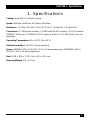
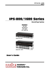
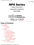
JANUARY 2002
SWI081A
SWI081AE
SWI082
Dual-Port Network Power Switch
CUSTOMER
SUPPORT
INFORMATION
Order toll-free in the U.S.: Call 877-877-BBOX (outside U.S. call 724-746-5500)
FREE technical support 24 hours a day, 7 days a week: Call 724-746-5500 or fax 724-746-0746
Mailing address: Black Box Corporation, 1000 Park Drive, Lawrence, PA 15055-1018
Web site: www.blackbox.com • E-mail: [email protected]
FCC AND IC RFI STATEMENTS AND CE NOTICE
FEDERAL COMMUNICATIONS COMMISSION
AND
INDUSTRY CANADA
RADIO FREQUENCY INTERFERENCE STATEMENTS
This equipment generates, uses, and can radiate radio-frequency energy, and if not
installed and used properly, that is, in strict accordance with the manufacturer’s
instructions, may cause interference to radio communication. It has been tested
and found to comply with the limits for a Class A computing device in accordance
with the specifications in Subpart B of Part 15 of FCC rules, which are designed to
provide reasonable protection against such interference when the equipment is
operated in a commercial environment. Operation of this equipment in a
residential area is likely to cause interference, in which case the user at his own
expense will be required to take whatever measures may be necessary to correct
the interference.
Changes or modifications not expressly approved by the party responsible
for compliance could void the user’s authority to operate the equipment.
This digital apparatus does not exceed the Class A limits for radio noise emission from
digital apparatus set out in the Radio Interference Regulation of Industry Canada.
Le présent appareil numérique n’émet pas de bruits radioélectriques dépassant les limites
applicables aux appareils numériques de la classe A prescrites dans le Règlement sur le
brouillage radioélectrique publié par Industrie Canada.
EUROPEAN UNION DECLARATION OF CONFORMITY
This equipment complies with the requirements of the European EMC Directive
89/336/EEC.
1
DUAL-PORT NETWORK POWER SWITCH
NORMAS OFICIALES MEXICANAS (NOM)
ELECTRICAL SAFETY STATEMENT
INSTRUCCIONES DE SEGURIDAD
1. Todas las instrucciones de seguridad y operación deberán ser leídas antes de
que el aparato eléctrico sea operado.
2. Las instrucciones de seguridad y operación deberán ser guardadas para
referencia futura.
3. Todas las advertencias en el aparato eléctrico y en sus instrucciones de
operación deben ser respetadas.
4. Todas las instrucciones de operación y uso deben ser seguidas.
5. El aparato eléctrico no deberá ser usado cerca del agua—por ejemplo, cerca
de la tina de baño, lavabo, sótano mojado o cerca de una alberca, etc..
6. El aparato eléctrico debe ser usado únicamente con carritos o pedestales que
sean recomendados por el fabricante.
7. El aparato eléctrico debe ser montado a la pared o al techo sólo como sea
recomendado por el fabricante.
8. Servicio—El usuario no debe intentar dar servicio al equipo eléctrico más allá
a lo descrito en las instrucciones de operación. Todo otro servicio deberá ser
referido a personal de servicio calificado.
9. El aparato eléctrico debe ser situado de tal manera que su posición no
interfiera su uso. La colocación del aparato eléctrico sobre una cama, sofá,
alfombra o superficie similar puede bloquea la ventilación, no se debe colocar
en libreros o gabinetes que impidan el flujo de aire por los orificios de
ventilación.
10. El equipo eléctrico deber ser situado fuera del alcance de fuentes de calor
como radiadores, registros de calor, estufas u otros aparatos (incluyendo
amplificadores) que producen calor.
11. El aparato eléctrico deberá ser connectado a una fuente de poder sólo del
tipo descrito en el instructivo de operación, o como se indique en el aparato.
2
NOM STATEMENT
12. Precaución debe ser tomada de tal manera que la tierra fisica y la polarización
del equipo no sea eliminada.
13. Los cables de la fuente de poder deben ser guiados de tal manera que no
sean pisados ni pellizcados por objetos colocados sobre o contra ellos,
poniendo particular atención a los contactos y receptáculos donde salen del
aparato.
14. El equipo eléctrico debe ser limpiado únicamente de acuerdo a las
recomendaciones del fabricante.
15. En caso de existir, una antena externa deberá ser localizada lejos de las lineas
de energia.
16. El cable de corriente deberá ser desconectado del cuando el equipo no sea
usado por un largo periodo de tiempo.
17. Cuidado debe ser tomado de tal manera que objectos liquidos no sean
derramados sobre la cubierta u orificios de ventilación.
18. Servicio por personal calificado deberá ser provisto cuando:
A: El cable de poder o el contacto ha sido dañado; u
B: Objectos han caído o líquido ha sido derramado dentro del aparato; o
C: El aparato ha sido expuesto a la lluvia; o
D: El aparato parece no operar normalmente o muestra un cambio en su
desempeño; o
E: El aparato ha sido tirado o su cubierta ha sido dañada.
3
DUAL-PORT NETWORK POWER SWITCH
TRADEMARKS USED IN THIS MANUAL
AT® is a registered trademark of International Business Machines Corporation.
Crosstalk® is a registered trademark of Digital Communications Associates, Inc.
ProComm® is a registered trademark of DATASTORM TECHNOLOGIES, INC.™
UNIX® is a registered trademark of UNIX System Laboratories, Inc.
Any other trademarks mentioned in this manual are acknowledged to be the property of the
trademark owners.
4
WARNINGS AND CAUTIONS
WARNING
There are no serviceable parts inside the Dual-Port Network Power
Switch! Do NOT attempt to repair or service this device yourself. YOU
MIGHT BE SHOCKED! Internal components must be serviced by
authorized personnel only.
This device should only be operated with the type of power source
indicated on the instrument nameplate. If you are not sure of the type of
power service available, consult your local power company.
Connect this unit only to a properly measured supply. Use only the
three-wire cord that is provided with the unit.
Reliable earthing (grounding) of this equipment must be maintained.
Give particular attention to supply connections when connecting to
power strips, rather than direct connections to the branch circuit.
CAUTION
Rackmount Installation: When installing this device in an instrument
rack, the following factors must be accounted for.
Enclosed Racks: Enclosed racks must provide adequate ventilation.
Make certain that the rack is not overly crowded and note that each unit
in the rack generates its own heat. An enclosed rack should have
louvered sides and a fan to circulate cooling air.
When mounting the unit in an enclosed rack with a ventilation fan at
the top of the rack, note that excessive heat generated by devices at the
bottom of the rack can be drawn upward and into the ventilation slots of
units located at the top. Provide adequate ventilation for equipment
installed at the bottom of the rack.
The ambient temperature within the rack may be greater than room
ambient. When installing the unit, do not compromise the amount of air
flow required for safe operation. The maximum temperature for the
equipment in this environment is 113°F (45°C). Consider the maximum
rated ambient.
Keep the installation stable by avoiding uneven loading.
Open Racks: Make certain that the rack frame does not block the
ventilation slots on the instrument cover. If the device is installed on
sliders, check the unit when seated all the way into the rack to make
certain that ventilation slots are not blocked.
CAUTION
Ventilation: Slots in the instrument cover are provided to allow
ventilation for heat dissipation. For safe, reliable operation, these
openings must not be covered or blocked.
5
DUAL-PORT NETWORK POWER SWITCH
CAUTION
Disconnect the power to the Switch and contact qualified service
personnel if:
1) The power cord becomes frayed or damaged.
2) Liquid has been spilled into the device or if the device has been
exposed to rain or water.
6
CONTENTS
Contents
Chapter
Page
1.
Specifications . . . . . . . . . . . . . . . . . . . . . . . . . . . . . . . . . . . . . . . . . . . . . . . . . . 9
2.
Introduction . . . . . . . . . . . . . . . . . . . . . . . . . . . . . . . . . . . . . . . . . . . . . . . . . . 10
2.1 Description . . . . . . . . . . . . . . . . . . . . . . . . . . . . . . . . . . . . . . . . . . . . . . . 10
2.2 Features . . . . . . . . . . . . . . . . . . . . . . . . . . . . . . . . . . . . . . . . . . . . . . . . . . 10
2.3 Front Panel . . . . . . . . . . . . . . . . . . . . . . . . . . . . . . . . . . . . . . . . . . . . . . . 11
2.4 Back Panel . . . . . . . . . . . . . . . . . . . . . . . . . . . . . . . . . . . . . . . . . . . . . . . . 12
3.
Installation . . . . . . . . . . . . . . . . . . . . . . . . . . . . . . . . . . . . . . . . . . . . . . . . . . . 13
3.1 Option Switches . . . . . . . . . . . . . . . . . . . . . . . . . . . . . . . . . . . . . . . . . . . 13
3.2 Console Port Connection. . . . . . . . . . . . . . . . . . . . . . . . . . . . . . . . . . . . 14
3.3 Connecting an External Modem . . . . . . . . . . . . . . . . . . . . . . . . . . . . . . 14
3.4 Connecting the Network Cable . . . . . . . . . . . . . . . . . . . . . . . . . . . . . . . 14
3.5 Power Supply Connection . . . . . . . . . . . . . . . . . . . . . . . . . . . . . . . . . . . 15
3.6 Connection to Switched Outlets . . . . . . . . . . . . . . . . . . . . . . . . . . . . . . 15
3.7 Reset Unit to Defaults. . . . . . . . . . . . . . . . . . . . . . . . . . . . . . . . . . . . . . . 15
3.7.1 Default Parameters Option . . . . . . . . . . . . . . . . . . . . . . . . . . . . . 16
3.7.2 Default Button (Local). . . . . . . . . . . . . . . . . . . . . . . . . . . . . . . . . 16
4.
Startup/Configuration . . . . . . . . . . . . . . . . . . . . . . . . . . . . . . . . . . . . . . . . . 17
4.1 System Mode and User Mode . . . . . . . . . . . . . . . . . . . . . . . . . . . . . . . . 17
4.2 Communicating with the Dual-Port Network Power Switch . . . . . . . . 18
4.3 Switch Command/Menu Conventions . . . . . . . . . . . . . . . . . . . . . . . . . 20
4.4 Defining General Parameters . . . . . . . . . . . . . . . . . . . . . . . . . . . . . . . . 20
4.5 Plug Parameters . . . . . . . . . . . . . . . . . . . . . . . . . . . . . . . . . . . . . . . . . . . 23
4.6 Network Parameters . . . . . . . . . . . . . . . . . . . . . . . . . . . . . . . . . . . . . . . . 24
4.7 Save Configuration Parameters . . . . . . . . . . . . . . . . . . . . . . . . . . . . . . . 27
5.
Operation . . . . . . . . . . . . . . . . . . . . . . . . . . . . . . . . . . . . . . . . . . . . . . . . . . . . 28
5.1 Accessing the Switch Command Mode . . . . . . . . . . . . . . . . . . . . . . . . . 28
5.2 Displaying Plug Status. . . . . . . . . . . . . . . . . . . . . . . . . . . . . . . . . . . . . . . 29
5.3 Boot/On/Off Commands . . . . . . . . . . . . . . . . . . . . . . . . . . . . . . . . . . . 30
5.4 The Default Command. . . . . . . . . . . . . . . . . . . . . . . . . . . . . . . . . . . . . . 32
5.5 The Automated Mode . . . . . . . . . . . . . . . . . . . . . . . . . . . . . . . . . . . . . . 32
5.6 Other Commands . . . . . . . . . . . . . . . . . . . . . . . . . . . . . . . . . . . . . . . . . . 33
5.6.1 Login as Different User . . . . . . . . . . . . . . . . . . . . . . . . . . . . . . . . 33
5.6.2 Reset Network Port. . . . . . . . . . . . . . . . . . . . . . . . . . . . . . . . . . . . 33
5.6.3 Exit/Disconnect . . . . . . . . . . . . . . . . . . . . . . . . . . . . . . . . . . . . . . 34
7
DUAL-PORT NETWORK POWER SWITCH
Contents (continued)
Chapter
Page
5.7 Manual Operation . . . . . . . . . . . . . . . . . . . . . . . . . . . . . . . . . . . . . . . . . 34
5.8 Operating Tips . . . . . . . . . . . . . . . . . . . . . . . . . . . . . . . . . . . . . . . . . . . . 34
6.
Saving and Restoring Configuration Parameters . . . . . . . . . . . . . . . . . . . . 36
6.1 Sending Parameters to a File . . . . . . . . . . . . . . . . . . . . . . . . . . . . . . . . . 36
6.2 Restoring Saved Parameters . . . . . . . . . . . . . . . . . . . . . . . . . . . . . . . . . . 36
Appendix A. Interface Descriptions. . . . . . . . . . . . . . . . . . . . . . . . . . . . . . . . . . . 38
A.1 Console Port Interface . . . . . . . . . . . . . . . . . . . . . . . . . . . . . . . . . . . . . . 38
A.2 Modem Port Interface . . . . . . . . . . . . . . . . . . . . . . . . . . . . . . . . . . . . . . 38
Appendix B. Optional Rackmounting Bracket Instructions . . . . . . . . . . . . . . . 39
Appendix C. Troubleshooting . . . . . . . . . . . . . . . . . . . . . . . . . . . . . . . . . . . . . . . 41
C.1 Calling Black Box . . . . . . . . . . . . . . . . . . . . . . . . . . . . . . . . . . . . . . . . . . 41
C.2 Shipping and Packaging. . . . . . . . . . . . . . . . . . . . . . . . . . . . . . . . . . . . . 41
8
CHAPTER 1: Specifications
1. Specifications
Coding: Serial ASCII, 8 bits, No parity
Speed: 2400 bps, 9600 bps, 19.2 kbps, 38.4 kbps
Indicators: (7) LEDs: ON, RDY, RXD, DCD, NET, Outlet ON 1, Outlet ON 2
Connectors: (1) DB9 male modem; (1) DB9 male RS-232 console; (1) RJ-45 female
10BASE-T Ethernet; (2) NEMA 5-15 AC power outlets; (1) IEC-320 inlet (line cord
supplied)
Operating Temperature: 32 to 113°F (0 to 45°C)
Relative Humidity: 10 to 90% noncondensing
Power: SWI081A: 105 to 120 VAC, 60 Hz, 15 amps maximum; SWI081AE: 210 to
250 VAC, 50 Hz, 10 amps maximum
Size: 2.6"H x 8"W x 7.2"D (6.6 x 20.3 x 18.3 cm)
Shipping Weight: 6 lb. (2.7 kg)
9
DUAL-PORT NETWORK POWER SWITCH
2. Introduction
2.1 Description
Network equipment sometimes locks up, requiring a service call just to flip the
power switch to perform a simple reboot. The Dual-Port Network Power Switch
gives network administrators the ability to perform this function from anywhere on
the LAN/WAN, or if the network is down, to simply dial-in from a modem for outof-band power control.
2.2 Features
• Intelligent power control: The Dual-Port Network Power Switch can
communicate over any TCP/IP network using generic Telnet, or out-of-band
using an external modem and terminal emulation. Each outlet can be assigned
an individual password, device name, reboot delay time, and unique power-up
default status.
• Security and co-location features: Address-specific IP security masks prevent
unauthorized network access to the Dual-Port Network Power Switch
command mode. The Switch provides two password security levels: system level
and user level. The system password allows access to all configuration and
command functions. The user password allows access only to assigned plugs.
User-level security features are ideal for co-location applications, where
multiple users may be allowed plug-specific access to the Dual-Port Network
Power Switch.
• Easy to use, easy to configure: Reboots and plug switching are controlled by
simple ASCII commands sent to the Switch via network, modem, or from a
local PC. Setup and configuration are simple; easy-to-follow menus lead you
through the installation process.
• Turn On/Off any AC-powered device via Telnet, modem, or local terminal.
• Two individual switched outlets.
• Two levels of outlet-specific password security plus network security.
10
CHAPTER 2: Introduction
2.3 Front Panel
As shown in Figure 2-1, the Dual-Port Network Power Switch front panel includes a
series of LED indicators. Descriptions of the LEDs are listed below.
1
2
3
4
5
6
Figure 2-1. Front panel.
1. ON: Lights when AC power is applied to the Dual-Port Network Power Switch.
2. RDY: Flashes when the Dual-Port Network Power Switch is ready to receive
commands.
3. RXD: Lights when the Dual-Port Network Power Switch receives commands.
4. DCD: Lights when the modem port detects the carrier.
5. NET: Lights when a Telnet session is in progress.
6. Plug indicators and manual control buttons: An on/off indicator and manual
control button for each switched plug. To manually switch a plug on or off,
press and hold the appropriate manual control button for one second; the
corresponding plug will be toggled on or off.
NOTE
If desired, you can disable the manual control buttons as described in
Section 4.4.
11
DUAL-PORT NETWORK POWER SWITCH
2.4 Back Panel
1
2
5
3
6
4
7
8
9
Figure 2-2. Back panel.
1. Power inlet: Supplies power for the Dual-Port Network Power Switch’s
command functions and the two switched plugs.
2. Circuit breaker: SWI081A: 115 VAC, 15 amps or SWI081AE: 230 VAC,
10 amps.
3. Master power switch: This switch must be in the on position in order for the
Dual-Port Network Power Switch to function. This switch is not used to set the
on/off status of the switched outlets.
4. Network port and activity indicator: An RJ-45 Ethernet port for connection to
your TCP/IP network. To communicate via network, you must first specify the
IP Address, Subnet Mask, and Gateway Address as described in Section 4.6.
5. Switched AC outlets: SWI081A: Each outlet can switch up to 15 amps. Total
for both outlets must not exceed 15 amps. SWI081AE: Each outlet can switch
up to 10 amps. Total for both outlets must not exceed 10 amps.
6. Option switches: A bank of four DIP switches which select default settings for
the baud rate and other features.
7. Modem port: A male RS-232, DB9 connector, DTE configuration. For
connection to an external modem.
8. Console port: A male RS-232, DB9 connector, DTE configuration. For
connection to a local PC.
9. Default button: Resets the unit to default settings as described in Section 3.7.
12
CHAPTER 3: Installation
3. Installation
3.1 Option Switches
The option switches select default settings for the baud rate, command echo, boot
delay, and disconnect timeout. Default settings selected via the option switches will
be used when the unit is reset to default parameters as described in Section 3.7.
NOTE
Although the option switches select default settings for these features,
the Dual-Port Network Power Switch’s configuration menus can also be
used to select operating parameters as described in Chapter 4.
Option switch settings are described below:
• Baud rate: The default baud rate for the console port and modem port. This
rate will be selected after a power interruption and when the unit is reset to
default parameters.
• Boot delay: The default boot delay setting. When a boot cycle is initiated, the
boot delay determines the length of time that the switched outlet will remain
off until power is restored.
• Command echo: The default setting for the command echo for the console
port, modem port, and network port. When enabled, commands entered at
your keyboard will be sent to the Dual-Port Network Power Switch and echoed
back to your display monitor.
• Disconnect Timeout: The default disconnect timeout value. This determines
how long the Switch will wait for additional commands before automatically
disconnecting.
NOTE
When the Dual-Port Network Power Switch times out, DTR will drop, and
the modem disconnect and initialize strings will be sent.
13
DUAL-PORT NETWORK POWER SWITCH
Table 3-1. Option switch settings.
Switch
Function
Up
Down
1
Default baud rate
38.4 kbps
9600 bps*
2
Default boot delay
10 seconds
5 seconds*
3
Default command echo
Enable
Disable*
4
Default disconnect timeout
30 minutes
2 minutes*
*Default setting.
3.2 Console Port Connection
The console port is a male DB9 connector wired in a DTE configuration (similar to
an AT computer). It’s used for connection to a local PC or control device. Section
A.1 describes the console port interface.
3.3 Connecting an External Modem
When connecting directly to an external modem, use a standard AT® to modem
cable. Make certain the modem is initialized at the same baud rate as the Dual-Port
Network Power Switch (option switch 1). The modem must be set to auto-answer,
in one ring. Please refer to the modem user’s guide for more information.
Section 4.4 describes the procedure for defining the modem command strings.
Section A.2 describes the modem port interface.
3.4 Connecting the Network Cable
The network port is an RJ-45 Ethernet jack. It’s used for connection to a TCP/IP
network. Connect your 10BASE-T cable to the network port. Before attempting to
access the unit via network, please assign the IP address, gateway address, and
subnet mask as described in Section 4.6.
14
CHAPTER 3: Installation
3.5 Power Supply Connection
Connect the Dual-Port Network Power Switch to an appropriate power supply.
CAUTION
This device should only be operated with the type of power source
indicated on the instrument nameplate. If you are not sure of the type of
power service available, please contact your local power company.
Reliable earthing (grounding) of this unit must be maintained. Give
particular attention to supply connections when connecting to power
strips, rather than directly to the branch circuit.
Check nameplate ratings to ensure that there is no overloading of
supply circuits that could have an effect on overcurrent protection and
supply wiring.
3.6 Connection to Switched Outlets
The main power switch must be on in order for the Dual-Port Network Power
Switch to operate. When the unit is powered on, the two AC outlets will be
switched on or off, as specified by the user-defined power-up default (see
Section 4.5). On SWI081A models (115 VAC), each outlet can switch up to
15 amps AC (total for both outlets must not exceed 15 amps). On SWI081AE
models (230 VAC), each outlet can switch up to 10 amps AC (total for both outlets
must not exceed 10 amps).
3.7 Reset Unit to Defaults
If option switch settings are changed, the new settings will not be applied until the
unit is reset to default settings. There are two ways to reset the unit to defaults: via
default parameters or via the default button.
NOTE
When these reset procedures are performed, all user-selected
parameters, including passwords and port names, will be lost. Before
performing these reset procedures, we strongly recommend that you
save configuration parameters to an ASCII text file as described in
Chapter 6.
15
DUAL-PORT NETWORK POWER SWITCH
3.7.1 DEFAULT PARAMETERS OPTION
This method allows default parameters to be set without affecting the on/off status
of the Dual-Port Network Power Switch’s two switched plugs. To reset the unit to
default parameters, proceed as follows:
1. Access the Dual-Port Network Power Switch’s command mode (see
Section 5.1).
2. At the TPS> command prompt, type /G and press [Enter]. The General
Parameters menu will appear.
3. From the General Parameters menu, type A and press [Enter]. If command
confirmation is enabled, the unit will display a “Sure?” prompt. Type Y and
press [Enter] to proceed with the reset procedure. After a brief pause,
parameters will be reset to default values.
NOTE
If the default parameters function is invoked via the network port, the IP
address will not be reset. If this function is invoked via the console port
or modem port, the IP Address will be reset.
3.7.2 DEFAULT BUTTON (LOCAL)
Typically, this method is used when devices have not been connected to the DualPort Network Power Switch and you have immediate access to the installation site.
NOTE
This method will temporarily switch all plugs off.
Set the master power switch to the OFF position. Press and hold the Default
button, located on the instrument back panel. Place the master power switch in the
ON position. Wait about 5 seconds, then release the Default button.
16
CHAPTER 4: Startup/Configuration
4. Startup/Configuration
4.1 System Mode and User Mode
To restrict access to sensitive command functions, the Dual-Port Network Power
Switch features two separate operating modes: system mode and user mode.
The system mode allows access to all configuration menus, command functions,
and status screens. When the system mode is active, boot/on/off commands can
be directed to either of the two switched outlets. The System Mode Status screen
shows on/off conditions for both switched outlets and lists currently defined
system parameters.
The user mode allows limited access to command functions and status screens;
users are not allowed to access configuration menus. When the user mode is active,
boot/on/off commands can only be directed to the specific outlet(s) that are
allowed by the user password that was entered at login. If a different user password
is assigned to each Dual-Port Network Power Switch outlet, then a user who
accesses the Dual-Port Network Power Switch using the password for plug 1 is not
allowed to boot or switch plug 2. On the other hand, if the same user password is
assigned to both Dual-Port Network Power Switch outlets, then that user will be
able to direct commands to both plugs. The User Mode Status screen only shows
conditions at the outlet(s) allowed by the user password; system parameters are not
displayed.
When properly configured, the Dual-Port Network Power Switch will display a
password prompt when the unit is contacted via the console port, modem port, or
network port. The password entered at this prompt determines whether the unit
will start up in system mode or user mode. If the system password (defined via the
General Parameters menu) is entered, the system mode will be active. If the user
password (defined via the Plug Configuration menus) is entered, the user mode
will be active.
If the system password is not defined, the Dual-Port Network Power Switch will not
display the password prompt and will always start up in system mode. Once the
system password has been defined, individual users can be granted access by
assigning passwords to the Dual-Port Network Power Switch’s two switched plugs as
described in Section 4.5.
17
DUAL-PORT NETWORK POWER SWITCH
4.2 Communicating with the Dual-Port Network Power Switch
To configure the unit or invoke command functions, you must first connect to the
Dual-Port Network Power Switch and access the command mode.
1. The Dual-Port Network Power Switch is transparent to parity and will accept 7
or 8 bit characters, but will always answer back at 8 bits, no parity. Make
certain your communication program (for example, ProComm® or
Hyperterminal) is set for the appropriate baud rate, bits, and parity.
a) Via modem: Start your communications program. Dial the external
modem connected to the Dual-Port Network Power Switch. Wait for the
connect message and proceed to step 2.
b) Via Local PC: Start your communications program and then press [Enter].
c) Via Network: During initial configuration, the Dual-Port Network Power
Switch cannot be accessed via the network port. After network parameters
have been defined (see Section 4.6), the unit may then be accessed via
network as described in Section 5.1.
2. Password: If the system password has been defined, the unit will display the
password prompt. Key in either the system password or user password, and
press [Enter]. If the system password has not been defined, the prompt will
not be displayed.
NOTE
The password is case sensitive.
3. If you enter the system password, the Dual-Port Network Power Switch will
display the System Help screen (Figure 4-1). If you enter the user password,
the Dual-Port Network Power Switch will display the User Help screen
(Figure 4-2).
18
CHAPTER 4: Startup/Configuration
Dual-Port Network Power Switch v1.00
Site: BLACK BOX CORPORATION
Commands:
Display
/H
Display this Help Screen
/S[P]
Display Plug Status, {p} with Passwords
Configuration
/G
View/Set
/P [n]
View/Set
/N
View/Set
/DL
Download
Control
/D
/Boot<n>
/On<n>
/Off<n>
/T
/R
/X
General Parameters
Plug Parameters
Network Parameters
Configuration to File
Set Plugs to Default Settings
Boot Plug n
Turn On Plug n
Turn Off Plug n
Reset Network Interface
Relogin as Different User
Exit/Disconnect
+--------------------------------+
|[n]=Optional Plug Name or Number|
|<n>=Required Plug Name or Number|
|n+n=Plug n and Plug n
|
|n:n=Plug n through Plug n
|
|*=All Plugs with Access
|
+--------------------------------+
Figure 4-1. System Help screen.
Dual-Port Network Power Switch v1.00
Site: BLACK BOX CORPORATION
Commands:
Display
/H
/S[P]
Display this Help Screen
Display Plug Status
Control
/D
/Boot <n>
/On <n>
/Off <n>
/X
Set Plugs to Default Settings
Boot Plug n
Turn On Plug n
Turn Off Plug n
Exit/Disconnect
<n>=Required Plug Name or Number
n+n=Plug n and Plug n
n:n=Plug n through Plug n
*=All Plugs with Access
TPS>
Figure 4-2. User Help screen.
19
DUAL-PORT NETWORK POWER SWITCH
4.3 Switch Command/Menu Conventions
When invoking Dual-Port Network Power Switch commands and selecting items
from configuration menus, note the following:
• All Dual-Port Network Power Switch commands can be invoked at the TPS>
command prompt, or from the General Parameters menu, Port Parameters
menus, or Network Parameters menu.
• Dual-Port Network Power Switch commands are not case sensitive. All DualPort Network Power Switch commands are invoked by pressing [Enter].
• To select an item from a Dual-Port Network Power Switch menu, key in the
number for the item and press [Enter]. To exit from a menu, press [Esc] at any
time. Parameters defined up to that point will be saved.
• To display the Help Screen, type /H [Enter].
• The ,Y option can temporarily suppress the “Sure?” confirmation prompt.
The ,Y option is entered at the end of the command line, immediately
following the command or argument. For example, to reset the network port
without displaying the “Sure?” prompt, type /T,Y [Enter]. To switch off Plug 2
without the “Sure?” prompt, type /OFF 2,Y [Enter].
4.4 Defining General Parameters
When the “TPS>” prompt appears, type /G [Enter] to display the General
Parameters menu (Figure 4-3). Note that this menu is not available in User mode.
GENERAL PARAMETERS:
1. System Password:
2. Site ID:
3. Modem Init. String:
4. Modem Disc. String:
5. Baud Rate:
6. Command Echo:
7. Disconnect Timeout:
8. Command Confirmation:
9. Automated Mode:
10. Button Mode:
(undefined)
(undefined)
ATE0M0Q1&C1&D2S0=1
(undefined)
9600,N,8,1
Off
2 Min
On
On
On
A. Default Parameters
Enter Selection or <ESC> to Exit…
Figure 4-3. General Parameters menu (System mode only).
20
CHAPTER 4: Startup/Configuration
The General Parameters menu offers the following options:
1. System Password: (Up to 16 characters, case sensitive.) When the system
password is defined, the Dual-Port Network Power Switch will display a
prompt before allowing access to command mode. If the system password is
entered, the Dual-Port Network Power Switch will start up in system mode. To
define the system password, type 1 and press [Enter]. (Default = undefined.)
NOTE
If the system password is not defined, the password prompt will not be
displayed, and the Dual-Port Network Power Switch will always start up
in system mode.
2. Site ID: Defines a text string (up to 32 characters) that denotes the installation
site. To define the Site ID, type 2 and press [Enter]. (Default = undefined.)
3. Modem Initialization String: To define the modem initialization string (up to
32 characters), type 3 and press [Enter]. For more information on the
initialization string, please refer to the user’s guide for your external modem.
Make certain that the modem is set to auto-answer in one ring. (Default =
ATE0M0Q1&C1&D2S0=1.)
4. Modem Disconnect String: To define the Disconnect String (up to 32
characters), type 4, press [Enter], and follow the instructions in the submenu.
For more information, please refer to the user’s guide for your external
modem. (Default = undefined.)
5. Baud Rate: To select the baud rate for the modem port and console port, type
5, press [Enter], and follow the instructions in the submenu. Make certain to
select a rate that is compatible with the external modem and/or the device
connected to the console port. (Default value determined by option switch 1;
Factory setting = 9600.)
NOTE
When this setting is changed, the new baud rate will not be applied until
you exit and then re-enter the Dual-Port Network Power Switch
Command Mode.
6. Command Echo: Enables/disables the command echo. When enabled,
commands sent to the Dual-Port Network Power Switch will be echoed back
to your PC, allowing keystrokes to be displayed . To enable/disable the echo,
type 6, press [Enter], and follow the instructions in the submenu. (Default
determined by option switch 3; Factory setting = Disabled.)
21
DUAL-PORT NETWORK POWER SWITCH
7. Disconnect Timeout: Determines how long the Dual-Port Network Power
Switch will wait for additional commands. Type 7, press [Enter], and follow
the instructions in the submenu. (Default determined by option switch 4;
Factory setting = 2 Min)
8. Command Confirmation: When enabled, the Dual-Port Network Power
Switch will display a “Sure?” prompt before completing the /T, /X, /R,
/BOOT, /ON, /OFF, /D, and “A” commands, and will also display the
System Status screen after commands are successfully completed. When
disabled, the “Sure?” prompt is suppressed, and the Status screen is not sent
when commands are complete. (Default = On.)
9. Automated Mode: When enabled, the Dual-Port Network Power Switch will
execute the /ON, /OFF, /BOOT, /D, and /X commands without displaying
the confirmation prompt, status screen, or confirmation messages. This allows
the Switch to be controlled by a device that generates commands to control
power switching without human interaction. For more information, please
refer to Section 5.5. (Default = Off.)
NOTE
When this option is enabled, Dual-Port Network Power Switch password
security functions are disabled, and users are able to access system
level menus and control both plugs without entering a password.
10. Button Mode: Enables/disables the manual plug control buttons on the DualPort Network Power Switch front panel. When enabled, the Switch’s two
switched plugs can be toggled on and off by pressing and holding the manual
control button for approximately one second. When disabled, the manual
control buttons will have no effect. (Default = On.)
A. Default Parameters: Resets the Dual-Port Network Power Switch to the default
values specified by the option switches. In addition, all menu-selected
parameters, including port names and passwords, will be lost. If command
confirmation is disabled, the “Sure?” prompt will not be sent.
NOTE
If the Default Parameters function is invoked via the network port,
the IP address is not reset. If this function is invoked via the console
port or modem port, the IP address will be reset.
After defining the general parameters, press [Esc] to exit from the General
Parameters menu.
22
CHAPTER 4: Startup/Configuration
4.5 Plug Parameters
The Plug Parameters menus are used to assign names and select parameters for
each of the two switched outlets. There is a separate Plug Parameters menu for
each outlet. Note that the Plug Parameters menus are not available in user mode.
In addition to selecting parameters for each outlet, the Plug Parameters menus
also allow you to assign an individual user password to each plug. If the same user
password is assigned to both plugs, then that password will allow the user to direct
boot/on/off commands to both switched plugs. If a separate password is assigned
to each plug, then each password will only allow access to its corresponding plug.
To access the Plug Parameters menus from the TPS> prompt, type /P n and press
[Enter] (where n is the number or name of one of the two switched outlets).
PLUG #1 PARAMETERS:
1.
2.
3.
4.
Plug Name:
Password:
Boot Delay:
Power Up Default:
(undefined)
(undefined)
5 Sec
On
Enter Selection or <ESC> to Exit…
Figure 4-4. Plug Parameters menu (plug 1 shown).
The Plug Parameters menu (Figure 4-4) offers the following options:
1. Plug Name: (Up to 16 characters.) Assigns a name to the plug. Typically, this
name describes the piece of equipment that is connected to the switched
outlet. When plug names are assigned, boot/on/off commands can be
invoked using the name or number of the desired plug. (Default =
undefined.)
2. Password: (Up to 16 characters.) Assigns a user password to this plug. When a
user password is assigned, the plug is then “owned” by that password. When a
user password is entered at login, the user will have access to only the plug(s)
that are owned by this password. (Default = undefined.)
NOTE
If the system password is defined and the plug’s user password is not
defined, then the system password will “own” this plug; only the system
mode will be able to control the plug.
23
DUAL-PORT NETWORK POWER SWITCH
NOTES
If you want to allow a single user to access both switched plugs, assign
the same user password to both plugs.
If you want to “split” plug access between two different users (each
user controls their own plug), then assign a different user password to
each plug.
3. Boot Delay: During a boot cycle, power to the plug is first switched off and
then switched back on. The boot delay is the length of time which elapses
between the time when power is switched off and the time that power is
restored. The boot delay can be 1, 5, 10, 15, 30, or 60 seconds. (Default
determined by option switch 2; Factory setting = 5 seconds.)
4. Power Up Default: Determines how this plug will react when the /D (default)
command is invoked, or after a power interruption. Each plug can be
automatically switched on or off as specified by the power-up default.
(Default = On.)
After plug parameters have been defined, press [Esc] to exit from the Plug
Parameters menu.
4.6 Network Parameters
To communicate with the Dual-Port Network Power Switch via network, the IP
address, subnet mask, and gateway address must first be defined via the Network
Parameters menu. If desired, this menu also allows you to implement IP security
features, which can restrict command mode access based on the user’s IP address.
Settings for network parameters depend upon the configuration of your individual
network. Please contact your network administrator for appropriate settings, then
assign parameters as described in this section.
To access the Network Parameters menu (Figure 4-5), type /N and press [Enter].
Note that this menu is not available in user mode.
24
CHAPTER 4: Startup/Configuration
NETWORK PARAMETERS:
1.
2.
3.
4.
IP Address:
Subnet Mask:
Gateway Address:
IP Security
MAC Address:
(undefined)
(undefined)
(undefined)
00-40-05-5e-f3-90
Enter Selection or <ESC> to Exit…
Figure 4-5. Network Parameters menu (system mode only).
The following options are available:
1. IP Address: Defines the IP address for the Dual-Port Network Power Switch.
Type 1, press [Enter], and follow the instructions in the submenu. (Default =
undefined.)
2. Subnet Mask: Defines the subnet mask for the Dual-Port Network Power
Switch. Type 2, press [Enter], and follow the instructions in the submenu.
(Default = undefined.)
3. Gateway Address: Defines the gateway address for the Dual-Port Network
Power Switch. Type 3, press [Enter], and follow the instructions in the
submenu. (Default = undefined.)
4. IP Security: Sets up the IP Security feature as described below.
5. Mac Address: Displays the unit’s Mac address. Note that this item is not used
to redefine the Mac address.
IMPLEMENTING IP SECURITY
The Dual-Port Network Power Switch can be configured to restrict unauthorized IP
addresses from telneting to the unit. This allows you to grant Telnet access to only
a specific group of IP addresses, or block a particular IP address from gaining
access. In the default state, the Dual-Port Network Power Switch accepts incoming
IP connections from all hosts.
25
DUAL-PORT NETWORK POWER SWITCH
IP SECURITY
1. Security Mask #1:
2. Mask #1 Action:
3. Security Mask #2:
4. Mask #2 Action:
5. Security Mask #3:
6. Mask #3 Action:
7. Security Mask #4:
8. Mask #4 Action:
9. Security Mask #5:
10. Mask #5 Action:
(undefined)
Permit
(undefined)
Permit
(undefined)
Permit
(undefined)
Permit
(undefined)
Permit
Enter Selection or <ESC> to Exit…
Figure 4-6. IP Security menu.
To configure the IP security feature, proceed as follows:
1. Access the Network Parameters menu as described on the previous page.
Note that the Network Parameters menu is not available in user mode.
2. When the Network Parameters menu appears, type 4 and press [Enter] to
access the IP Security menu (Figure 4-6).
3. The IP Security menu lists five IP security “masks” along with the selected
permit/deny action for each mask.
a) Each security mask prompt is used to define a specific IP address or range
of IP addresses. Each mask action prompt is used to define the
permit/deny action for the corresponding mask.
b) Masks are listed in order of ascending priority; Mask 1 has the lowest
priority, Mask 5 has the highest priority.
c) Masks have a cumulative effect; high-priority masks supersede the effect of
lower-priority masks.
d) Each IP address consists of a series of four eight-bit numbers. The number
255 is used as a wild card.
Example 1: Deny access to all hosts except 192.1.1.5:
Security Mask #1: 255.255.255.255 Mask #1 Action: Deny
Security Mask #2: 192.1.1.5 Mask #2 Action: Permit
Since 255 is a wild card, Mask #1 blocks all IP addresses. Mask #2 then specifically
grants access to 192.1.1.5 only.
26
CHAPTER 4: Startup/Configuration
Example 2: Allow access only by addresses that begin with 192.
Security Mask #1: 255.255.255.255 Mask #1 Action: Deny
Security Mask #2: 192.255.255.255 Mask #2 Action: Permit
Since 255 is a wild card, Mask 1 blocks all IP addresses. Mask 2 then grants access to
all addresses that begin with 192.
Example 3: Allow access only by addresses that begin with 192, deny access to
192.1.1.5.
Security Mask #1: 255.255.255.255 Mask #1 Action: Deny
Security Mask #2: 192.255.255.255 Mask #2 Action: Permit
Security Mask #3: 192.1.1.5 Mask #3 Action: Deny
Since 255 is a wild card, Mask 1 blocks all IP addresses. Mask 2 then grants access to
all addresses that begin with 192. Finally, Mask 3 specifically blocks access for
192.1.1.5 only.
NOTES
Mask #5 has priority over the other four masks. If Mask #5 is set to deny
access by “255.255.255.255” (all wild cards), all IP addresses will be
blocked, and you will not be able to access the Dual-Port Network Power
Switch Command mode via network. Access will only be allowed via the
console port or modem port.
When using the wild card address “255.255.255.255” to block access by
all IP addresses, make certain that at least one higher priority mask
permits access by your IP address.
4.7 Save Configuration Parameters
After the unit has been completely configured, we recommend saving parameters
to an ASCII file as described in Chapter 6. This allows quick recovery if the unit is
reset to default parameters, or the configuration is accidentally deleted or altered.
27
DUAL-PORT NETWORK POWER SWITCH
5. Operation
Your PC or Control Device must send ASCII characters at the same data rate as the
Dual-Port Network Power Switch. The Switch accepts 8 bits, no parity, or 7 bits,
even or odd parity, but will always answer back at 8 bits, no parity.
5.1 Access the Switch Command Mode
In order to invoke commands, you must first access the Command mode.
Commands can be sent to the Switch via network or modem, or from a local PC
connected to the console port. To access the Command mode, proceed as follows:
1. Contact the Dual-Port Network Power Switch:
a) Via network: Telnet to the Switch’s IP address. For example, if the IP
address is 192.1.1.1, on a UNIX® system the Telnet command would be as
follows:
$ telnet 192.1.1.1 [Enter]
NOTES
In order to contact the Switch via telnet, you must first define the unit’s
network parameters as described in Section 4.6.
If the Telnet connection to the Switch is refused, this may mean that the
unit is busy, or that the IP security feature has denied the connection.
b) Via modem: Start your communications program (for example,
ProComm). Dial the external modem that is connected to the Switch,
then wait for the connect message.
c) Via console port: Start your communications program and press [Enter].
Make certain you are communicating via the correct COM port.
2. Password: If the system password has been defined, a prompt will be
displayed. Key in your system or user password and press [Enter].
3. Disconnect: If you want to end the session, type /X and press [Enter] (or
disconnect using Telnet software).
28
CHAPTER 5: Operation
5.2 Displaying Plug Status
The Status screen displays the on/off state and selected parameters for the
switched plugs. To display the Status screen, type /S and press [Enter].
NOTE
Although the /S command is available in both user and system mode,
the System Status screen includes more information than the User
Status screen.
When the system mode is active, the /S command will produce the screen shown
in Figure 5-1. It lists status and parameters for both switched plugs, console port
parameters, and modem command strings.
NOTE
In system mode, the /S command will also accept an argument which
will display the user password for each plug. To display plug
passwords, access the system mode, type /SP, and press [Enter].
Dual-Port Network Power Switch v1.00 Site: BLACK BOX CORPORATION
Plug
1
2
Name
ROUTER_A
ROUTER_B
Modem Init. String:
Modem Disc. String:
Communication Settings:
Command Echo:
Disconnect Timeout:
Command Confirmation:
Automated Mode:
Button Mode:
Status
ON
OFF
Boot Delay
15 Sec
15 Sec
Password
(defined)
(defined)
Default
ON
OFF
ATE0M0Q1&C1&D2S0=1
+++ATZ
9600,N,8,1
OFF
30 Min
ON
OFF
ON
“/H” for Help
Figure 5-1. System Status screen (passwords hidden).
29
DUAL-PORT NETWORK POWER SWITCH
When the user mode is active, the /S command will produce the screen shown in
Figure 5-2. It lists the status and parameters only for the plug(s) owned by the user
password entered at login. If a separate user password has been assigned to the
other plug, the User Mode Status screen will not list the status for that plug. In user
mode, plug passwords cannot be displayed.
Dual-Port Network Power Switch v1.00 Site: BLACK BOX CORPORATION
Plug
2
Name
ROUTER_B
Modem Init. String:
Modem Disc. String:
Communication Settings:
Command Echo:
Disconnect Timeout:
Command Confirmation:
Automated Mode:
Button Mode:
Status
OFF
Boot Delay
15 Sec
Password
(defined)
Default
ON
ATE0M0Q1&C1&D2S0=1
+++ATZ
9600,N,8,1
OFF
30 Min
ON
OFF
ON
“/H” for Help
Figure 5-2. User Status screen.
5.3 Boot/On/Off Commands
These commands are used to boot or toggle the on/off status of the Dual-Port
Network Power Switch’s two switched plugs. If the same password has been applied
to both switched plugs, commands can be directed to plug 1, plug 2, or both
switched plugs. If a separate user password has been assigned to each plug, then
commands can only be applied to the plug that is owned by the user password that
was entered at login. Plugs may be specified by name or number.
NOTES
When user mode is active, commands will only be applied to plugs
owned by the user’s password. Commands will not affect a plug owned
by another user password.
When system mode is active, commands can be applied to both
switched plugs.
Wait for the “TPS>” prompt to appear before entering commands. The
prompt will not reappear until the previous command is complete.
Commands are not case sensitive. All commands are invoked by
pressing [Enter].
30
CHAPTER 5: Operation
NOTE
If command confirmation is enabled, the Switch will display the Status
screen after the boot/on/off commands are successfully completed.
1. Switch plug(s) on: To power-on a plug, type /ON n and press [Enter] (where
“n” is the number or name of the desired plug). For example:
/ON 1 or /ON ROUTER
2. Switch plug(s) off: To power-off a plug, type /OFF n and press [Enter]
(where “n” is the number or name of the desired plug). Note that the /OFF
command can also be entered as /OF. For example:
/OFF 2 or /OF ROUTER
3. Boot plug(s): To initiate a boot cycle, type /BOOT n and press [Enter] (where
“n” is a the number or name of the desired plug). Note that the /BOOT
command can also be entered as /BO. For example:
/BOOT 1 or /BO ATMSWTCH
4. Suppress command confirmation prompt: To execute a boot/on/off
command without displaying the “Sure?” prompt, include the ,Y option in
the command line. The ,Y option is entered immediately following the
command argument. For example:
/ON ROUTER,Y or /BOOT 2,Y
APPLYING COMMANDS TO BOTH PLUGS
As described below, boot/on/off commands can be applied to plug 1, plug 2, or
both switched plugs:
NOTES
Commands can only be applied to both plugs when the unit is operating
in System mode, or when both plugs are owned by the same user
password.
When commands are applied to both plugs, the Switch will delay for
approximately one second between actions. For example, when
switching both plugs on, the Dual-Port Network Power Switch will
switch plug 1 on, delay one second, then switch plug 2 on.
1. Single plug: To apply a command to a single owned plug, enter the number
or name for that plug. For example:
/ON 2 or /ON ROUTER.
31
DUAL-PORT NETWORK POWER SWITCH
2. Both plugs: To apply a command to both owned plugs, enter an asterisk in
place of the name or number. For example:
/ON * or /BO *
5.4 The Default Command
The default command (/D) sets plugs to their default on/off status. The default
status is set using the Plug Parameters menus described in Section 4.5. Plugs will be
set to these defaults when /D is invoked or after a power interruption. To set both
plugs to defaults, type /D and press [Enter].
NOTES
When user mode is active, this command will only be applied to plugs
owned by the user’s password. The command will not be applied to a
plug that is owned by another user password.
When the system mode is active, this command will be applied to both
plugs.
This command will always be applied to all owned plugs. It cannot be
directed only to a specific plug.
5.5 The Automated Mode
The automated mode allows the Dual-Port Network Power Switch to perform
on/off/boot/default/exit commands without displaying menus or generating
response messages. Automated mode allows the Switch to be controlled by a
computer (or another automatic system) that can generate commands to control
power switching functions without human intervention.
When the automated mode is enabled, the /ON, /OFF, /BOOT, /D, and /X
commands are executed without a “Sure?” confirmation prompt and without
command response messages; the only reply to these commands is the “TPS>”
prompt, which is displayed when the command is complete.
NOTE
When Automated Mode is enabled, a) all Switch password security
functions are disabled, b) you can access system level command
functions (including the configuration menus), and c) you can control
both plugs without entering a password. If you need to enable the
automated mode but want to restrict network access to Switch
configuration menus, enable and configure the IP Security function as
described in Section 4.6.
32
CHAPTER 5: Operation
To enable/disable the automated mode, access the General Parameters menu and
proceed as described in Section 4.4. When the automated mode is enabled, Switch
functions will change as follows:
1. All password security suppressed: When you attempt to access the Switch’s
command mode, the password prompt will not be displayed at either the
Telnet port, modem port, or console port. Unless restricted by the IP Security
function, you will be allowed to access system level command functions and
control both plugs. At the console port, all commands are immediately
accepted, whether the port is awake or asleep.
2. Status screen suppressed: The status screen will not be automatically displayed
after commands are successfully executed. Note however, that the /S
command can still be invoked to display the status screen as required.
3. “Sure?” prompt suppressed: All commands are executed without prompting
for user confirmation.
4. Error messages suppressed: If the [Enter] key is pressed without entering a
command, the Switch will not respond with the “Invalid Command” message.
Note, however, that an error message will still be generated if commands are
invoked using invalid formats or arguments.
All other status display and configuration commands will still function as normal.
5.6 Other Commands
5.6.1 LOGIN AS DIFFERENT USER
The /R command is used to re-login using a different password. When invoked,
the Switch will display the password prompt, allowing you to enter a different
password in order to access the other plug or system level command functions. The
/R command is often used to switch from user mode to system mode.
The /R command is available in both system mode and user mode. To login as a
different user, type /R, press [Enter], then key in a different valid password at the
prompt. To suppress the “Sure?” prompt, type /R,Y [Enter].
5.6.2 RESET NETWORK PORT
The /T command is used to reinitialize the Switch network card. The /T
command is not available in user mode. To reset the network port, type /T and
press [Enter]. To suppress the “Sure?” prompt, type /T,Y [Enter].
33
DUAL-PORT NETWORK POWER SWITCH
NOTE
The /T command can only be issued via the console port or modem port.
The /T command can not be invoked via the Network Port.
5.6.3 EXIT/DISCONNECT
To exit from the command mode and discontinue connection to the unit, type /X
and press [Enter]. The Switch will display the “DISCONNECT” message. To
suppress the “Sure?” prompt, type /X,Y [Enter].
5.7 Manual Operation
In addition to the command-driven functions, the Dual-Port Network Power
Switch’s two switched plugs can also be toggled on and off manually. To manually
toggle a plug on or off, press the appropriate manual control button and hold it
down for approximately one second; the corresponding plug will be toggled on or
off.
NOTE
The manual control buttons can also be disabled via the General
Parameters menu as described in Section 4.4.
5.8 Operating Tips
When connecting to the Dual-Port Network Power Switch via network, modem or
console port, keep in mind the following factors:
1. One connection at a time: Only one port can access the command mode at a
time. When a command port is busy, the Switch will react as follows:
a) Network port busy: If a second user attempts to connect via the modem
port, the Switch will send a busy message. If a second user attempts to
connect via the console port, the port will not wake.
b) Modem port busy: If a second user attempts to connect via the network
port, the connection will be refused. If a second user attempts to connect
via the console port, the port will not wake.
c) Console port busy: If a second user attempts to connect via the network
port, the connection will be refused. If a second user attempts to connect
via the modem port, the console port will disconnect and the modem port
will be granted access; the modem port has priority over the console port.
34
CHAPTER 5: Operation
2. Ping packet size: The Switch will not accept ping packets larger than
approximately 1000 bytes.
If you have any questions regarding configuration or operation, contact Black Box
Technical Support as described in Appendix C.
35
DUAL-PORT NETWORK POWER SWITCH
6. Saving and Restoring
Configuration Parameters
After the Dual-Port Network Power Switch has been properly configured,
parameters can be downloaded and saved as an ASCII text file. Later, if the
configuration is accidentally altered, the file with the saved parameters can be
uploaded to automatically reconfigure the unit without the need to manually
assign each parameter.
Saved parameters can also be uploaded to other Dual-Port Network Power
Switches. This allows rapid setup when several Switches will be configured with the
same parameters.
The “Save Parameters” procedure can be performed from any terminal emulation
program (for example, ProComm®, Crosstalk®, Hyperterminal, etc.) that allows
downloading of ASCII files.
6.1 Sending Parameters to a File
1. Start your communications program and access the Switch’s command mode
using the system level password.
2. When the Switch’s command prompt appears, type /DL and press [Enter].
The Switch will prompt you to prepare your communications program. Set up
your communications program to receive an ASCII download, and specify a
name for the file that will receive the saved parameters (for example,
TPS.PAR).
3. When the communications program is ready to receive the file, return to the
Switch’s command mode, and press [Enter] to proceed.
4. The Switch will send a series of ASCII command lines which specify the
currently selected Switch parameters.
6.2 Restoring Saved Parameters
This section describes the procedure for using ProComm to send saved parameters
to the Switch.
1. Start your communications program and access the Switch’s command mode
using the system level password.
36
CHAPTER 6: Saving and Restoring Configuration Parameters
2. Configure your communications program to upload an ASCII text file.
3. Upload the file with the saved parameters. If necessary, key in the file name
and directory path.
4. When the upload is complete, make certain to terminate the communications
program’s upload mode.
NOTES
The current on/off status of each Switch plug will not be saved or
restored. However, the selected default on/off setting for each plug will
be saved and restored.
When the configuration file is sent to the Switch via telnet, the unit’s IP
address, subnet mask, and gateway address cannot be altered.
5. Type /SP and press [Enter]. The Switch will display the status screen with
passwords revealed. Check the status screen to make certain that saved
parameters have been restored.
37
DUAL-PORT NETWORK POWER SWITCH
Appendix A. Interface Descriptions
A.1 Console Port Interface
Figure A-1. Console port interface.
A.2 Modem Port Interface
Figure A-2. Modem port interface.
38
APPENDIX B: Optional Mounting Bracket Instructions
Appendix B. Optional
Rackmounting Bracket Instructions
The Dual-Port Network Power Switch can either be placed on a desktop, installed
in a 19" equipment rack, or mounted on a wall. This appendix describes the
procedures for installing the optional rackmount kit (part number SWI082).
When installing the Switch in an instrument rack, the following factors must be
accounted for:
• Enclosed Racks: Enclosed racks must provide adequate ventilation. Make
certain that the rack is not overly crowded, and note that each unit in the rack
generates its own heat. An enclosed rack should have louvered sides and a fan
to circulate cooling air. The maximum temperature for the equipment in this
type of environment is 113°F (45°C).
• Enclosed Racks: When mounting the Switch in an enclosed rack with a
ventilation fan at the top of the rack, note that excessive heat generated by
devices at the bottom of the rack can be drawn upwards into the ventilation
slots on units located at the top. Make certain to provide adequate ventilation
for equipment installed at the bottom of the rack.
• Open Racks: Make certain that the rack frame does not block the ventilation
slots on the instrument cover. If the device is installed on sliders, check the
unit when seated all the way into the rack to make certain that ventilation slots
are not blocked.
To install the optional rackmount kit (part number SWI082), refer to Figure B-1
and proceed as follows.
1. Disconnect the Switch from the power supply. Remove the screws that secure
the Switch’s top cover to the chassis. (There are two screws on each side of the
unit.) Do not remove the cover from the chassis.
2. Align the rackmount brackets with the Switch as shown in Figure B.1.
39
DUAL-PORT NETWORK POWER SWITCH
Rackmount brackets
Dual-Port Network
Power Switch
back panel
Figure B-1. Rackmounting.
3. Use the longer screws (supplied with the rackmount kit) to secure the
rackmount brackets and top cover to the Switch chassis. Make certain that the
vents on the sides are not obstructed by the rackmount brackets.
40
APPENDIX C: Troubleshooting
Appendix C. Troubleshooting
C.1 Calling Black Box
If you determine that your Dual-Port Network Power Switch is malfunctioning, do
not attempt to alter or repair the unit. It contains no user-serviceable parts.
Contact Black Box at 724-746-5500.
Before you do, make a record of the history of the problem. We will be able to
provide more efficient and accurate assistance if you have a complete description,
including:
• the nature and duration of the problem.
• when the problem occurs.
• the components involved in the problem.
• any particular application that, when used, appears to create the problem or
make it worse.
C.2 Shipping and Packaging
If you need to transport or ship your Dual-Port Network Power Switch:
• Package it carefully. We recommend that you use the original container.
• If you are shipping the Dual-Port Network Power Switch for repair, make sure
you include everything that came in the original package. Before you ship,
contact Black Box to get a Return Authorization (RA) number.
41
© Copyright 2002. Black Box Corporation. All rights reserved.
1000 Park Drive
•
Lawrence, PA 15055-1018
•
724-746-5500
•
Fax 724-746-0746