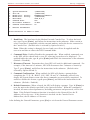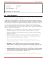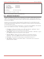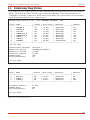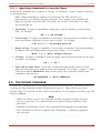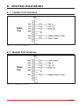
1
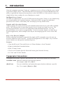
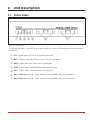
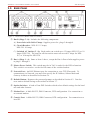
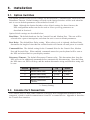
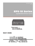
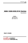
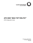
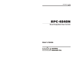
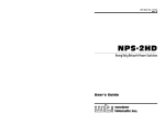
WTI Part No.: 12927 Rev. D NPS Series Network Power Switch Models NPS-115 & NPS-230 (Firmware Version 2.04 and Higher) User's Guide 5 Sterling · Irvine · California 92618 (949) 586-9950 · Toll Free: 1-800-854-7226 Fax: (949) 583-9514 · http://www.wti.com Table of Contents 1. Introduction . . . . . . . . . . . . . . . . . . . . . . . . . . . . . . . . . . . . . . . . . . . . . . 1 2. Unit Description. . . . . . . . . . . . . . . . . . . . . . . . . . . . . . . . . . . . . . . . . . . . 2 2.1. Front Panel. . . . . . . . . . . . . . . . . . . . . . . . . . . . . . . . . . . . . . . . . . . . 2 2.2. Back Panel . . . . . . . . . . . . . . . . . . . . . . . . . . . . . . . . . . . . . . . . . . . . 3 3. Installation . . . . . . . . . . . . . . . . . . 3.1. Option Switches . . . . . . . . . . . . 3.2. Console Port Connection. . . . . . . 3.3. Connecting an External Modem . . . 3.4. Connecting the Network Cable . . . 3.5. Power Supply Connection . . . . . . 3.6. Connection to Switched Outlets. . . 3.7. Reset Unit to Defaults . . . . . . . . 3.7.1. Default Parameters Option . 3.7.2. Default Button (Local) . . . 4. Start-Up / Configuration . . . . . . . . . . . . . . . . . . . . . . . . . . . . . . . . . . . . . . 7 4.1. System Mode and User Mode . . . . . . . . . . . . . . . . . . . . . . . . . . . . . . . . . 7 4.2. Communicating with the NPS . . . . . . . . . . . . . . . . . . . . . . . . . . . . . . . . . 8 4.3. NPS Command/Menu Conventions . . . . . . . . . . . . . . . . . . . . . . . . . . . . . 10 4.4. Defining General Parameters . . . . . . . . . . . . . . . . . . . . . . . . . . . . . . . . 10 4.5. Plug Parameters . . . . . . . . . . . . . . . . . . . . . . . . . . . . . . . . . . . . . . . . 12 4.6. Network Parameters . . . . . . . . . . . . . . . . . . . . . . . . . . . . . . . . . . . . . . 13 4.6.1. Implementing IP Security . . . . . . . . . . . . . . . . . . . . . . . . . . . . . . 14 4.7. Save Configuration Parameters . . . . . . . . . . . . . . . . . . . . . . . . . . . . . . . 15 5. Operation . . . . . . . . . . . . . . . . . . . . . 5.1. Access the NPS Command Mode . . . . 5.2. Displaying Plug Status . . . . . . . . . . 5.3. Boot/On/Off Commands . . . . . . . . . 5.3.1. Applying Commands to Several 5.4. The Default Command . . . . . . . . . . 5.5. Other Commands . . . . . . . . . . . . . 5.5.1. Login as Different User . . . . . 5.5.2. Reset Network Port . . . . . . . 5.5.3. Exit / Disconnect. . . . . . . . . 5.6. Operating Tips . . . . . . . . . . . . . . . 6. Saving and Restoring Configuration Parameters . . . . . . . . . . . . . . . . . . . . . . . 21 6.1. Sending Parameters to a File . . . . . . . . . . . . . . . . . . . . . . . . . . . . . . . . . 21 6.2. Restoring Saved Parameters . . . . . . . . . . . . . . . . . . . . . . . . . . . . . . . . . 22 . . . . . . . . . . . . . . . . . . . . . . . . . . . . . . . . . . . . . . . . . . . . . . . . . . . . . . . . . . . . . . . . . . . . . . . . . . . . Plugs . . . . . . . . . . . . . . . . . . . . . . . . . . . . . . . . . . . . . . . . . . . . . . . . . . . . . . . . . . . . . . . . . . . . . . . . . . . . . . . . . . . . . . . . . . . . . . . . . . . . . . . . . . . . . . . . . . . . . . . . . . . . . . . . . . . . . . . . . . . . . . . . . . . . . . . . . . . . . . . . . . . . . . . . . . . . . . . . . . . . . . . . . . . . . . . . . . . . . . . . . . . . . . . . . . . . . . . . . . . . . . . . . . . . . . . . . . . . . . . . . . . . . . . . . . . . . . . . . . . . . . . . . . . . . . . . . . . . . . . . . . . . . . . . . . . . . . . . . . . . . . . . . . . . . . . . . . . . . . . . . . . . . . . . . . . . . . . . . . . . . . . . . . . . . . . . . . . . . . . . . . . . . . . . . . . . . . . . . . . . . . . . . . . . . . . . . . . . . . . . . . . . . . . . . . . . . . . . . . . . . . . . . . . . . . . . . . . . . . . . . . . . . . . . . . . . . . . . . . . . . . . . . . . . . . . . . . . . . . . . . . . . . . . . . . . . . . . . 4 4 4 5 5 5 5 5 6 6 16 16 17 18 19 19 20 20 20 20 20 i NPS Series - Network Power Switches, User's Guide Table of Contents Appendices A. Interface Descriptions . . . . . . . . . . . . . . . . . . . . . . . . . . . . . . . . . . . . . Apx-1 A.1. Console Port Interface . . . . . . . . . . . . . . . . . . . . . . . . . . . . . . . . . . Apx-1 A.2. Modem Port Interface . . . . . . . . . . . . . . . . . . . . . . . . . . . . . . . . . . Apx-1 B. Specifications . . . . . . . . . . . . . . . . . . . . . . . . . . . . . . . . . . . . . . . . . . Apx-2 C. Customer Service . . . . . . . . . . . . . . . . . . . . . . . . . . . . . . . . . . . . . . . . Apx-3 Index . . . . . . . . . . . . . . . . . . . . . . . . . . . . . . . . . . . . . . . . . . . . . . . . . Index-1 List of Figures 1. 2. 3. 4. 5. 6. 7. 8. 9. 10. A.1. A.2. Front Panel . . . . . . . . . . . . . . . . . . . . . . . . . . . . . . . . . . . . . . . . . . . . . . 2 Back Panel (Model NPS-115 Shown) . . . . . . . . . . . . . . . . . . . . . . . . . . . . . . . 3 System Help Screen . . . . . . . . . . . . . . . . . . . . . . . . . . . . . . . . . . . . . . . . . 9 User Help Screen . . . . . . . . . . . . . . . . . . . . . . . . . . . . . . . . . . . . . . . . . . 9 General Parameters Menu (System Mode Only) . . . . . . . . . . . . . . . . . . . . . . . . 11 Plug Parameters Menu (Plug 1 Shown) . . . . . . . . . . . . . . . . . . . . . . . . . . . . . 12 Network Parameters Menu (System Mode Only) . . . . . . . . . . . . . . . . . . . . . . . 13 IP Security Menu . . . . . . . . . . . . . . . . . . . . . . . . . . . . . . . . . . . . . . . . . . 14 System Status Screen (Passwords Hidden) . . . . . . . . . . . . . . . . . . . . . . . . . . . 17 User Status Screen . . . . . . . . . . . . . . . . . . . . . . . . . . . . . . . . . . . . . . . . . 17 Console Port Interface . . . . . . . . . . . . . . . . . . . . . . . . . . . . . . . . . . . . Apx-1 Modem Port Interface . . . . . . . . . . . . . . . . . . . . . . . . . . . . . . . . . . . . . Apx-1 ii 1. Introduction Network equipment sometimes "locks-up", requiring a service call just to flip the power switch to perform a simple reboot. The NPS Network Power Switch gives network administrators the ability to perform this function from anywhere on the LAN/WAN, or if the network is down, to simply dial-in from a modem for out-of-band power control. Intelligent Power Control The NPS can communicate over any TCP/IP network using generic Telnet, or out-of-band using an external modem and terminal emulation. Each outlet can be assigned an individual password, device name, reboot delay time and unique power-up default status. Security and Co-Location Features Address specific IP security masks prevent unauthorized network access to the NPS command mode. The NPS provides two password security levels; System level and User level. The System password allows access to all configuration and command functions. The User password allows access only to assigned plugs. User level security features are ideal for colocation applications, where multiple users may be allowed plug-specific access to the NPS unit. Easy to Use, Easy to Configure Reboots and plug switching are controlled by simple ASCII commands sent to the unit via network, modem or from a local PC. Set-up and configuration is also simple; easy-to-follow menus lead the user through the installation process. Features: · Turn On/Off any AC Powered Device via Telnet, Modem or Local Terminal. · Eight (8) Individual Switched Outlets · Dual 15 Amp Circuits · Two Levels of Outlet Specific Password Security plus Network Security · 115 VAC and 230 VAC Models Typographic Conventions Throughout this manual, typefaces and characters have been used to denote the following: COURIER FONT Indicates characters typed on the keyboard. For example, /ON 3 or /OFF 5. [Bold Font] Text set in bold face and enclosed in square brackets indicates a specific key. For example, [Enter] or [Esc]. 1 2. Unit Description 2.1. Front Panel Figure 1: Front Panel As shown in Figure 1, the NPS front panel includes a series of LED indicators which function as follows: À ON: Lights when AC Power is applied to the NPS. Á RDY: Flashes when the NPS is ready to receive commands. Â RXD: Lights when the NPS receives commands. Ã DCD: Lights when the Modem Port detects the Carrier. Ä NET: Lights when a Telnet session is in progress. Å Bus A Indicators (1 - 4): Light when the corresponding Plug is switched On. Æ Bus B Indicators (5 - 8): Light when the corresponding Plug is switched On. 2 NPS Series - Network Power Switches, User's Guide Unit Description 2.2. Back Panel Figure 2: Back Panel (Model NPS-115 Shown) À Bus B (Plugs 5 - 8): Includes the following components: A) Power Inlet with Cable Clamp: Supplies power for plugs 5 through 8. B) Circuit Breaker: NPS-115: 15 Amps; NPS-230: 10 Amps C) Switched AC Outlets (5 - 8): Each outlet can switch up to 15 Amps (NPS-115) or 10 Amps (NPS-230). The total for all four outlets must not exceed 15 Amps for NPS115, or 10 Amps for NPS-230. Á Bus A (Plugs 1 - 4): Same as Item 1 above, except the Bus A Power Inlet supplies power to plugs 1 through 4. Â Master Power Switch: This switch must be in "On" in order for the NPS to function. This switch is not used to set the On/Off status of the switched outlets. Ã Network Port: An RJ45 Ethernet port for connection to your TCP/IP network. To communicate via Network, you must first specify the IP Address, Subnet Mask and Gateway Address as described in Section 4.6. Ä Default Button: Bypasses the password prompt as described in Section 4.2. Can also reset unit to default settings as described in Section 3.7. Å Option Switches: A bank of four DIP Switches which select default settings for the baud rate and other features. Æ Modem Port: A Male RS-232, DB9 Connector, DTE configuration. For connection to an external modem. Ç Console Port: A Male RS-232, DB9 Connector, DTE configuration. For connection to a local PC. 3 3. Installation 3.1. Option Switches The Option Switches select default settings for the Baud Rate, Command Echo, Boot Delay and Disconnect Timeout. Default settings selected via the Option Switches will be used when the unit is reset to default parameters as described in Section 3.7. Note: Although the Option Switches select default settings for these features, the NPS configuration menus can also be used to select operating parameters as described in Section 4. Option Switch settings are described below: Baud Rate: The default baud rate for the Console Port and Modem Port. This rate will be selected after a power interruption, and when the unit is reset to default parameters. Boot Delay: The default Boot Delay setting. When a boot cycle is initiated, the Boot Delay determines the length of time that the switched outlet will remain off until power is restored. Command Echo: The default setting for the Command Echo for the Console Port, Modem Port and Network Port. When enabled, commands entered at your keyboard will be sent to the NPS and echoed back to your display monitor. Disconnect Timeout: The default Disconnect Timeout value. This determines how long the NPS will wait for additional commands before automatically disconnecting. Note that when the NPS times out, DTR will drop, and the modem disconnect string and initialize string will be sent. Switch Function Up Down 1 Default Baud Rate 38.4K bps 9600 bps* 2 Default Boot Delay 10 Sec. 5 Sec.* 3 Default Command Echo Enable Disable* 4 Default Disconnect Timeout 30 Min 2 Min* * = Factory Setting 3.2. Console Port Connection The Console Port is a male, DB9 connector, wired in a DTE configuration (similar to an AT computer), which is used for connection to a local PC or control device. Appendix A describes the Console Port interface. 4 NPS Series - Network Power Switches, User's Guide Installation 3.3. Connecting an External Modem When connecting directly to an external modem, use a standard AT to Modem cable. Make certain the modem is initialized at the same baud rate as the NPS (Option Switch 1). The modem must be set to Auto-Answer, in one ring. Please refer to the modem user’s guide for more information. Section 4.4 describes the procedure for defining the modem command strings. Appendix A describes the modem port interface. 3.4. Connecting the Network Cable The Network Port is an RJ45 Ethernet jack, for connection to a TCP/IP network. Connect your 10Base-T cable to the Network Port. Before attempting to access the unit via network, please assign the IP Address, Gateway Address and Subnet Mask as described in Section 4.6. 3.5. Power Supply Connection The NPS includes two AC inputs. The Bus A input provides power for plugs 1 through 4. The Bus B input provides power for plugs 5 through 8. In order for the NPS to function, Bus A and/or Bus B must be connected to an appropriate power supply. 3.6. Connection to Switched Outlets The Main Power Switch must be "On" in order for the NPS to operate. When the unit is powered On, the eight AC outlets will be switched On or Off, as specified by the user defined Power-Up Default (see Section 4.5). · NPS-115: Each outlet can switch up to 15 Amps AC. The total for each Bus cannot exceed 15 Amps. · NPS-230: Each outlet can switch up to 10 Amps AC, The total for each Bus cannot exceed 10 Amps. 3.7. Reset Unit to Defaults If Option Switch settings are changed, the new settings will not be applied until the unit is reset to default settings. There are two ways to reset the unit to defaults: Note: When these reset procedures are performed, all user selected parameters, including passwords and port names will be lost. Prior to performing these reset procedures, it is strongly recommended to save configuration parameters to an ASCII text file as described in Section 6. 5 NPS Series - Network Power Switches, User's Guide Installation 3.7.1. Default Parameters Option This method allows default parameters to be set without effecting the On/Off status of the NPS's eight switched plugs. To reset the unit to default parameters, proceed as follows: 1. Access the NPS Command Mode (see Section 4.2 or 5.1). 2. At the NPS> command prompt, type /G and press [Enter]. The General Parameters menu will appear. 3. From the General Parameters menu, type A and press [Enter]. If command confirmation is enabled, the unit will display a prompt. Type Y and press [Enter] to proceed with the reset procedure. After a brief pause, parameters will be reset to default values. Note: If the Default Parameters function is invoked via the Network Port, the IP Address will not be reset. If this function is invoked via the Console Port or Modem Port, the IP Address will be reset. 3.7.2. Default Button (Local) Typically, this method is used when devices have not been connected to the NPS unit, and you have immediate access to the installation site. Note: This method will temporarily switch all plugs Off. Set the Master Power Switch to the OFF position. Press and hold the Default Button, located on the instrument back panel. Place the Master Power switch in the ON position. Wait about 5 seconds, and then release the Default Button. 6 4. Start-Up / Configuration 4.1. System Mode and User Mode In order to restrict access to sensitive command functions, the NPS features two separate operating modes; System Mode and User Mode. The System Mode allows access to all configuration menus, command functions and status screens. When the System Mode is active, Boot/On/Off commands can be directed to any of the eight switched outlets. The System Mode Status Screen shows On/Off conditions for all eight switched outlets, and lists currently defined system parameters. The User Mode allows limited access to command functions and status screens; users are not allowed to access configuration menus. When the User Mode is active, Boot/On/Off commands can only be directed to the specific outlets that are "owned" by that individual user. Outlets owned by other users cannot be switched. The User Mode Status Screen only shows conditions at the outlets owned by the user; system parameters are not displayed. When properly configured, the NPS will display a password prompt when the unit is contacted via the Console Port, Modem Port or Network Port. The password entered at this prompt determines whether the unit will start-up in System Mode or User Mode. If the System Password (defined via the General Parameters menu) is entered, the System Mode will be active. If the User Password (defined via the Plug Configuration Menus) is entered, the User Mode will be active. If the System Password is not defined, the NPS will not display the password prompt, and will always start-up in System Mode. Once the System Password has been defined, individual users can be granted access to specific outlets by assigning passwords to each plug as described in Section 4.5. 7 NPS Series - Network Power Switches, User's Guide Start-Up / Configuration 4.2. Communicating with the NPS In order to configure the NPS or invoke command functions, the user must first connect to the NPS and access command mode. 1. The NPS is transparent to parity and will accept 7 or 8 bit characters, but will always answer back at 8 bits, no parity. Make certain your communication program (e.g. ProComm orHyper Terminal) is set for the appropriate baud rate, bits and parity. a) Via Modem: Start your communications program. Dial the external modem connected to the NPS. Wait for the Connect message and proceed to Step 2. b) Via Local PC: Start your communications program and then press [Enter]. c) Via Network: During initial configuration, the NPS cannot be accessed via the Network Port. After network parameters have been defined (see Section 4.6), the unit may then be accessed via network as described in Section 5.1. 2. Password: If the System Password has been defined, the unit will display the Password Prompt. Key in either the System Password or User Password, and press [Enter]. If the system password has not been defined, the prompt will not be displayed. Notes: • The Password feature is case sensitive. • If you forget the System Password, contact the NPS via the Console Port. When the password prompt appears, press the default button to bypass the password requirement. When the NPS> prompt appears, type /G and press [Enter] to access the General Parameters menu. Use the General Parameters menu to assign a new System Password. 3. If the System Password is entered, the NPS will display the System Help Screen (Figure 3). If the User Password is entered, the NPS will display the User Help Screen (Figure 4). 8 NPS Series - Network Power Switches, User's Guide Start-Up / Configuration Network Power Switch v2.04 Site: WESTERN TELEMATIC, INC. Commands: Display /H /S[P] Display this Help Screen Display Plug Status, [P] with Passwords Configuration /G View/Set /P [n] View/Set /N View/Set /DL Download Control /D /Boot <n> /On <n> /Off <n> /T /R /X General Parameters Plug Parameters Network Parameters Configuration to File Set Plugs to Default Settings Boot Plug n Turn On Plug n Turn Off Plug n Reset Network Interface Relogin as Different User Exit/Disconnect +------------------------------------+ | [n] = Optional Plug Name or Number | | <n> = Required Plug Name or Number | | n+n = Plug n and Plug n | | n:n = Plug n through Plug n | | * = All Plugs with Access | +------------------------------------+ NPS> Figure 3: System Help Screen Network Power Switch v2.04 Site: WESTERN TELEMATIC, INC. Commands: Display /H /S Display this Help Screen Display Plug Status Control /D /Boot <n> /On <n> /Off <n> /X Set Plugs to Default Settings Boot Plug n Turn On Plug n Turn Off Plug n Exit/Disconnect +------------------------------------+ | <n> = Required Plug Name or Number | | n+n = Plug n and Plug n | | n:n = Plug n through Plug n | | * = All Plugs with Access | +------------------------------------+ NPS> Figure 4: User Help Screen 9 NPS Series - Network Power Switches, User's Guide Start-Up / Configuration 4.3. NPS Command/Menu Conventions When invoking NPS commands and selecting items from configuration menus, note the following: · All NPS commands can be invoked at the NPS> command prompt, or from the General Parameters Menu, Port Parameters Menus or Network Parameters Menu. · NPS commands are not case sensitive. All NPS commands are invoked by pressing [Enter]. · To select an item from an NPS menu, key in the number for the item and press [Enter]. To exit from a menu, press [Esc] at any time. Parameters defined up to that point will be saved. · To display the Help Screen, type /H [Enter]. · The ",Y" option can be used to temporarily suppress the "Sure?" confirmation prompt. The ",Y" option is entered at the end of the command line, immediately following the command or argument. For example, to reset the network port without displaying the "Sure?" prompt, type /T,Y [Enter], or to switch off Plug 2 without displaying the "Sure" prompt, type /OFF 2,Y [Enter]. 4.4. Defining General Parameters When the "NPS>" prompt appears, type /G [Enter] to display the General Parameters menu (Figure 5). Note that this menu is not available in User Mode. The General Parameters menu offers the following options: 1. System Password: (Up to 16 characters, case-sensitive) When the System Password is defined, the NPS will display a prompt before allowing access to command mode. If the System Password is entered, the NPS will start-up in System Mode. To define the System Password, type 1 and press [Enter]. (Default = undefined). Note: If the System Password is not defined, the password prompt will not be displayed, and the NPS will always start-up in System Mode. 2. Site ID: Defines a text string (up to 32 characters) that denotes the installation site. To define the Site ID, type 2 and press [Enter]. (Default = undefined). 3. Modem Initialization String: To define the Modem Initialization String (up to 32 characters), type 3 and press [Enter]. For more information on the initialization string, please refer to the user's guide for your external modem. Make certain that the modem is set to auto-answer in one ring. (Default = ATE0M0Q1&C1&D2S0=1). 4. Modem Disconnect String: To define the Disconnect String (up to 32 characters), type 4 press [Enter], and follow the instructions in the submenu. For more information, please refer to the user's guide for your external modem. (Default = undefined). 10 NPS Series - Network Power Switches, User's Guide Start-Up / Configuration GENERAL PARAMETERS: 1. 2. 3. 4. 5. 6. 7. 8. System Password: Site ID: Modem Init. String: Modem Disc. String: Baud Rate: Command Echo: Disconnect Timeout: Command Confirmation: A. Default Parameters (undefined) (undefined) ATE0M0Q1&C1&D2S0=1 (undefined) 9600,N,8,1 Off 30 Min On Enter Selection or <ESC> to Exit ... Figure 5: General Parameters Menu (System Mode Only) 5. Baud Rate: The baud rate for the Modem Port and Console Port. To select the baud rate, type 5 press [Enter], and follow the instructions in the submenu. Make certain to select a rate that is compatible with the external modem, and/or the device connected to the Console Port. (Default value is selected by Option Switch 1). Note: When this setting is changed, the new baud rate will not be applied until the user exits and then re-enters the NPS Command Mode. 6. Command Echo: Enables/Disables the command echo. When enabled, commands sent to the NPS will be echoed back to your PC, allowing keystrokes to be displayed . To enable/disable the echo, type 6, press [Enter] and follow the instructions in the submenu. (Default = Disabled). 7. Disconnect Timeout: Determines how long NPS will wait for additional commands. For example, if the timeout is 2 minutes, NPS will disconnect after 2 minutes of inactivity. Type 7, press [Enter], and follow the instructions in the submenu. (Default value selected by Option Switch 4). 8. Command Confirmation: When enabled, the NPS will display a prompt before completing the /T, /X, /R, /BOOT, /ON, /OFF, /D and "A" commands, and will also display the System Status screen after these commands are successfully completed. To enable or disable this feature, type 8 press [Enter], and follow the instructions in the submenu. (Default = Enabled). A. Default Parameters: When selected, the NPS will display a prompt. Type Y [Enter] to reset the unit to the defaults specified by the Option Switches. When this command is invoked, all menu selected parameters, including port names and passwords, will be lost. Note: If the Default Parameters function is invoked via the Network Port, the IP Address will not be reset. If this function is invoked via the Console Port or Modem Port, the IP Address will be reset. After defining the General Parameters, press [Esc] to exit from the General Parameters menu. 11 NPS Series - Network Power Switches, User's Guide Start-Up / Configuration PLUG #1 PARAMETERS: 1. 2. 3. 4. Plug Name: Password: Boot Delay: Power Up Default: (undefined) (undefined) 5 Sec On Enter Selection or <ESC> to Exit ... Figure 6: Plug Parameters Menu (Plug 1 Shown) 4.5. Plug Parameters The Plug Parameters menus are used to assign names and select parameters for each individual switched outlet. There is a separate Plug Parameters menu for each outlet. Note that the Plug Parameters menus are not available in User Mode. In addition to selecting parameters for each outlet, the Plug Parameters menus also determine which outlets will be controlled or "owned" by each User Password. A separate User Password can be assigned to each plug, or the same password can be assigned to several plugs. When a User Password is entered, the user will have access to all plugs owned by that password. To access the Plug Parameters menus from the NPS> prompt, type /P n and press [Enter] where n is the number or name of one of the eight switched outlets. The Plug Parameters menu (Figure 6) offers the following options: 1. Plug Name: (Up to 16 Characters) Assigns a name to the plug. Typically this name describes the equipment connected to the outlet. When plug names are assigned, Boot/On/Off commands can be invoked using the name or number of the desired plug. (Default = undefined). 2. Password: (Up to 16 Characters) Assigns a User Password to this plug. When a User Password is assigned, the plug is then "owned" by that User Password. When the password is entered at the prompt, the user will have access to this plug and all other plugs owned by this password. (Default = undefined). Note: If the System Password is defined, and the plug's User Password is not defined, then the System Password will "own" this plug, and only the System Mode will be able to control the plug. 3. Boot Delay: During a Boot cycle, power to the plug is first switched off and then switched back on. The Boot Delay is the length of time which elapses between the time when power is switched off and the time that power is restored. The Boot Delay can be 1, 5, 10, 15, 30 or 60 seconds. (Default value is selected by Option Switch 2). 4. Power-Up Default: Determines how this plug will react when the /D (default) command is invoked, or after a power interruption. Each plug can be automatically switched On or Off as specified by the Power-Up Default. (Default = On). After Plug Parameters have been defined, press [Esc] to exit from the Plug Parameters menu. 12 NPS Series - Network Power Switches, User's Guide Start-Up / Configuration NETWORK PARAMETERS: 1. 2. 3. 4. IP Address: Subnet Mask: Gateway Address: IP Security MAC Address: (undefined) (undefined) (undefined) 00-40-05-5e-f3-90 Enter Selection or <ESC> to Exit ... Figure 7: Network Parameters Menu (System Mode Only) 4.6. Network Parameters In order to communicate with the NPS via network, the IP Address, Subnet Mask and Gateway Address must first be defined via the Network Parameters menu. If desired, this menu also allows you to implement IP Security features, which can restrict command mode access based on the user's IP Address. Settings for network parameters depend upon the configuration of your individual network. Please contact your network administrator for appropriate settings, and then assign parameters as described in this section. To access the Network Parameters menu (Figure 7), type /N and press [Enter]. Note that this menu is not available in User Mode. The following options are available: 1. IP Address: Defines the IP Address for the NPS unit (Default = undefined). Type 1 press [Enter], and follow the instructions in the submenu. 2. Subnet Mask: Defines the Subnet Mask for the NPS unit (Default = undefined). Type 2 press [Enter], and follow the instructions in the submenu. 3. Gateway Address: Defines the Gateway Address for the NPS unit (Default = undefined). Type 3 press [Enter], and follow the instructions in the submenu. 4. IP Security: Sets up the IP Security feature as described in Section 4.6.1. 5. Mac Address: Displays the unit's MAC Address. Note that this item is not used to redefine the MAC Address. 13 NPS Series - Network Power Switches, User's Guide Start-Up / Configuration IP SECURITY 1. 2. 3. 4. 5. 6. 7. 8. 9. 10. Security Mask #1: Mask #1 Action: Security Mask #2: Mask #2 Action: Security Mask #3: Mask #3 Action: Security Mask #4: Mask #4 Action: Security Mask #5: Mask #5 Action: (undefined) Permit (undefined) Permit (undefined) Permit (undefined) Permit (undefined) Permit Enter Selection or <ESC> to Exit Figure 8: IP Security Menu 4.6.1. Implementing IP Security The NPS can be configured to restrict unauthorized IP addresses from Telneting to the unit. This allows the user to grant Telnet access to only a specific group of IP addresses, or block a particular IP address from gaining access. In the default state, the NPS accepts incoming IP connections from all hosts. To configure the IP Security feature, proceed as follows: 1. Access the Network Parameters menu as described in Section 4.6. Note that the Network Parameters menu is not available in User Mode. 2. When the Network Parameters menu appears, type 4 and press [Enter] to access the IP Security menu (Figure 8). 3. The IP Security menu lists five IP Security "masks" along with the selected permit/deny action for each mask. a) Each Security Mask prompt is used to define a specific IP address or range of IP addresses. Each Mask Action prompt is used to define the permit/deny action for the corresponding Mask. b) Masks are listed in order of ascending priority; Mask 1 has the lowest priority, Mask 5 has the highest priority. c) Masks have a cumulative effect; high priority masks supersede the effect of lower priority masks. d) Each IP Address consists of a series of four eight bit numbers. The number 255 is used as a wild card. 14 NPS Series - Network Power Switches, User's Guide Start-Up / Configuration Example 1: Deny access to all hosts except 192.1.1.5: Security Mask #1: Security Mask #2: 255.255.255.255 192.1.1.5 Mask #1 Action: Mask #2 Action: Deny Permit Since 255 is a wild card, Mask #1 blocks all IP Addresses. Mask #2 then specifically grants access to 192.1.1.5 only. Example 2: Allow access only by addresses that begin with 192. Security Mask #1: Security Mask #2: 255.255.255.255 192.255.255.255 Mask #1 Action: Mask #2 Action: Deny Permit Since 255 is a wild card, Mask 1 blocks all IP addresses. Mask 2 then grants access to all addresses that begin with 192. Example 3: Allow access only by addresses that begin with 192, deny access to 192.1.1.5. Security Mask #1: Security Mask #2: Security Mask #3: 255.255.255.255 192.255.255.255 192.1.1.5 Mask #1 Action: Mask #2 Action: Mask #3 Action: Deny Permit Deny Since 255 is a wild card, Mask 1 blocks all IP addresses. Mask 2 then grants access to all addresses that begin with 192. Finally, Mask 3 specifically blocks access by 192.1.1.5. Note: • Mask #5 has priority over the other four masks. If Mask #5 is set to deny access by "255.255.255.255" (all wild cards), all IP Addresses will be blocked, and you will not be able to access the NPS Command Mode via network. Access will only be allowed via the Console Port or Modem Port. • When using the wild card address "255.255.255.255" to block access by all IP Addresses, make certain that at least one higher priority mask permits access by your IP address. 4.7. Save Configuration Parameters After the unit has been completely configured, it is recommended to save parameters to an ASCII file as described in Section 6. This allows quick recovery in the event that the unit is reset to default parameters, or the configuration is accidentally deleted or altered. 15 5. Operation Your PC or Control Device must send ASCII characters at the same data rate as the NPS. The unit accepts 8 bits no parity, or 7 bits even or odd parity, but will always answer back at 8 bits, no parity. 5.1. Access the NPS Command Mode In order to invoke commands, the user must first access the NPS Command Mode. Commands can be sent to the NPS via Network or modem, or from a local PC connected directly to the Console Port. To access the Command Mode, proceed as follows: 1. Contact the NPS: a) Via Network: Telnet to the NPS unit's IP Address. For example, assuming the IP Address is "192.1.1.1", on a UNIX system the Telnet command would be invoked as follows: $ telnet 192.1.1.1 [Enter] Note: If the Telnet connection to the NPS is refused, this probably means that the unit is busy, or that the IP Security feature has denied the connection. b) Via Modem: Start your communications program (e.g. ProComm or Hyper Terminal). Dial the external modem that is connected to the NPS. Wait for the Connect Message. c) Via Console Port: Start your communications program (e.g. ProComm) and press [Enter]. Make certain you are communicating via the COM port connected to the NPS. 2. Password: If the System password has been defined, a prompt will be displayed. Key in your System or User Password, and press [Enter]. 3. Disconnect: To end the session, type /X and press [Enter] (or disconnect using Telnet software). 16 NPS Series - Network Power Switches, User's Guide Operation 5.2. Displaying Plug Status The Status Screens display the On/Off state and currently selected parameters for the switched plugs. To display the Status Screen, type /S and press [Enter]. Note that although the /S command is available in both User Mode and System Mode, the System Status Screen includes more information than the User Status Screen. Network Power Switch v2.04 Site: WESTERN TELEMATIC, INC. Plug | Name | Status | Boot Delay | Password | Default ------+------------------+--------+------------+------------------+--------1 | ROUTER_A | ON | 15 Sec | (defined) | ON 2 | ROUTER_B | OFF | 15 Sec | (defined) | OFF 3 | DSU/CSU | ON | 10 Sec | (defined) | ON 4 | ATMSWITCH_A | ON | 10 Sec | (defined) | ON 5 | ATMSWITCH_B | ON | 10 Sec | (defined) | OFF 6 | LINUX_1 | ON | 5 Sec | (defined) | ON 7 | LINUX_2 | ON | 30 Sec | (defined) | OFF 8 | GATEWAY | ON | 30 Sec | (undefined) | ON ------+------------------+--------+------------+------------------+------"/H" for Help Communication Settings: Modem Init. String: Modem Disc. String: Disconnect Timeout: Command Echo: Plug Confirmation: 9600,N,8,1 ATE0M0Q1&C1&D2S0=1 +++ATZ 30 Min OFF ON "/H" for Help Figure 9: System Status Screen (Passwords Hidden) Network Power Switch v2.04 Site: WESTERN TELEMATIC, INC. Plug | Name | Status | Boot Delay | Password | Default ------+------------------+--------+------------+------------------+--------3 | DSU/CSU | ON | 10 Sec | (defined) | ON 6 | LINUX_1 | ON | 5 Sec | (defined) | ON 7 | LINUX_2 | ON | 30 Sec | (defined) | OFF ------+------------------+--------+------------+------------------+--------Disconnect Timeout: Command Echo: Plug Confirmation: 30 Min OFF ON "/H" for Help Figure 10: User Status Screen 17 NPS Series - Network Power Switches, User's Guide Operation When the System Mode is active, the /S command will produce the screen shown in Figure 9, which lists status and parameters for all eight plugs, along with Console Port parameters, and modem command strings. Note that in System Mode, the /S command will also accept an argument which will display the User Password for each plug. To display plug passwords, access the System Mode, type /SP and press [Enter]. When the User Mode is active, the /S command will produce the screen shown in Figure 10, which lists the status and parameters only for the plugs owned by the User password entered at login. The User Mode Status Screen does not list the status of plugs owned by other user passwords. In User mode, plug passwords cannot be displayed. 5.3. Boot/On/Off Commands These commands are used to Boot or change the On/Off status of the NPS's eight switched plugs. Commands can be applied to one, several or all owned plugs. Plugs may be specified by name or number. • • • • • Note: When User Mode is active, commands will only be applied to plugs owned by the User's password. Commands will not effect plugs owned by other users. When System Mode is active, commands can be applied to all eight switched plugs. Wait for the "NPS>" prompt to appear before entering commands. The prompt will not reappear until the previous command is complete. Commands are not case sensitive. All commands are invoked by pressing [Enter]. If command confirmation is enabled, the NPS will display the Status Screen after the Boot/On/Off commands are successfully completed. 1. Switch Plug(s) On: To power-on a plug, type /ON n and press [Enter]. Where "n" is the number or name of the desired plug. For example: /ON 1 or /ON ROUTER 2. Switch Plug(s) Off: To power-off a plug, type /OFF n and press [Enter]. Where "n" is the number or name of the desired plug. Note that the "/OFF" command can also be entered as "/OF". For example: /OFF 5 or /OF ROUTER 3. Boot Plug(s): To initiate a Boot cycle, type /BOOT n and press [Enter]. Where "n" is a the number or name of the desired plug. Note that the "/BOOT" command can also be entered as "/BO". For example; /BOOT 3 or /BO ATMSWTCH 4. Suppress Command Confirmation Prompt: To execute a Boot/On/Off command without displaying the "Sure?" prompt, include the ",Y" option in the command line. The ",Y" option is entered immediately following the command argument. For example: /ON ROUTER,Y or /BOOT 3,Y 18 NPS Series - Network Power Switches, User's Guide Operation 5.3.1. Applying Commands to Several Plugs Boot/On/Off commands can be applied to one plug, several plugs, a range of plugs or all plugs as described below: Note: When commands are applied to several plugs, the NPS will delay for approximately 1 second between plug operations. For example, when switching all plugs On, the NPS will switch Plug 1 On, delay one second, switch Plug 2 On, delay one second, and etc. 1. Single Plug: To apply a command to a single plug, enter the number or name for that plug. For example: /ON 3 or /ON ROUTER. 2. Several Plugs: To apply a command to several plugs, enter plug names or numbers with each name/number separated by a plus sign or a space. For example: /OFF 1+3+7 or /OF ROUTER DSU/CSU 3. Range of Plugs: To apply a command to several plugs in sequence, enter the plug names or numbers with each name/number separated by a colon (:). For example: /BOOT 1:4 or /BOOT ROUTER:DSU/CSU 4. All Plugs: To apply a command to all owned plugs, enter an asterisk in place of the name or number. For example: /ON * or /BO * 5. Plugs with the Same Name: If you have assigned an identical plug name to several plugs, all such plugs can be addressed with one command. For example, if plugs 3, 4 and 5 have been named "ATMSWTCH", then all three plugs can be switched with the same command as shown below: /ON ATMSWTCH or /BOOT ATMSWTCH 5.4. The Default Command The Default Command (/D) sets all plugs to their default On/Off status. The default status is set using the Plug Parameters menus described in Section 4.5. Plugs will be set to these defaults when /D is invoked, or after a power interruption. To set all plugs to defaults, type /D and press [Enter]. Note: • When User Mode is active, this command will only be applied to plugs owned by the User's password. The command will not be applied to plugs owned by other passwords. • When the System Mode is active, this command will be applied to all eight plugs. • This command will always be applied to all owned plugs. It cannot be applied to only one plug. 19 NPS Series - Network Power Switches, User's Guide Operation 5.5. Other Commands 5.5.1. Login as Different User The /R command is used to re-login using a different password. When invoked, the NPS will display the password prompt, allowing the user to enter a different password in order to access other plugs or command functions. The /R command can be used to switch from User Mode to System Mode. The /R command is available in both System Mode and User Mode. To login as a different user, type /R, press [Enter], and then key in a different valid password at the prompt. To suppress the "Sure?" prompt, type /R,Y [Enter]. 5.5.2. Reset Network Port The /T command is used to reinitialize the NPS Network card. The /T command is not available in User Mode. To reset the Network Port, type /T and press [Enter]. To suppress the "Sure?" prompt, type /T,Y [Enter]. Note: The /T command can only be issued via the Console Port or Modem Port. The /T command can not be invoked via the Network Port. 5.5.3. Exit / Disconnect To exit from the NPS Command Mode and discontinue connection to the unit, type /X and press [Enter]. The NPS will display the "DISCONNECT" message. To suppress the "Sure?" prompt, type /X,Y [Enter]. 5.6. Operating Tips When connecting to the NPS unit via network, modem or console port, the following factors should be kept in mind: 1. One Connection at a Time: Only one port can access the command mode at a time. When a command port is busy, the NPS will react as follows: a) Network Port Busy: If a second user attempts to connect via the Modem Port, the NPS will send a busy message. If a second user attempts to connect via the Console Port, the port will not wake. b) Modem Port Busy: If a second user attempts to connect via the Network Port, the connection will be refused. If a second user attempts to connect via the Console Port, the port will not wake. c) Console Port Busy: If a second user attempts to connect via the Network Port, the connection will be refused. If a second user attempts to connect via the Modem Port, the Console Port will disconnect and the Modem Port will be granted access; the Modem Port has priority over the Console Port. 2. Ping Packet Size: The NPS will not accept Ping Packets larger than approximately 1000 bytes. If you have any questions regarding configuration or operation of the NPS unit, please contact WTI Technical Support as described in Appendix C. 20 21 NPS Series - Network Power Switches, User's Guide 6. Operation Saving and Restoring Configuration Parameters After the NPS has been properly configured, parameters can be downloaded and saved as an ASCII text file. Later, if the configuration is accidentally altered, the file with the saved parameters can be uploaded to automatically reconfigure the unit without the need to manually assign each parameter. Saved parameters can also be uploaded to other NPS units. This allows rapid set-up when several units will be configured with the same parameters. The "Save Parameters" procedure can be performed from any terminal emulation program (e.g. ProComm, Crosstalk, Hyperterminal, etc.), which allows downloading of ASCII files. 6.1. Sending Parameters to a File 1. Start your communications program and access the NPS command mode using the System Level Password. 2. When the NPS command prompt appears, type /DL and press [Enter]. The NPS will prompt you to prepare your communications program. Set up your communications program to receive an ASCII download, and specify a name for the file that will receive the saved parameters (e.g. NPS.PAR). 3. When the communications program is ready to receive the file, return to the NPS command mode, and press [Enter] to proceed. 4. The NPS will send a series of ASCII command lines which specify the currently selected NPS parameters. 22 A. Interface Descriptions A.1. Console Port Interface Figure A.1: Console Port Interface A.2. Modem Port Interface Figure A.2: Modem Port Interface Apx-1 B. Specifications Power Input/Output: Model NPS-115 (115 VAC) AC Inputs: Dual Bus Circuits, 15 Amps each Voltage: 100 - 140 VAC, 50/60 Hz Connectors: IEC-320 Inlet, Line Cords Supplied AC Outputs: Eight (8) Total; 1 - 4 Bus A, 5 - 8 Bus B. (15 Amp Rating) Connector: NEMA 5-15 Outlet Load: 15 Amps Total for each Bus Power Input/Output: Model NPS-230 (230 VAC) AC Inputs: Dual Bus Circuits, 10 Amps each Voltage: 205 - 250 VAC, 50/60 Hz Connectors: IEC-320 Inlet AC Outputs: Eight (8) Total; 1 - 4 Bus A, 5 - 8 Bus B (10 Amp Rating) Connector: IEC 320-C13 Outlet Load: 10 Amps Total for each Bus Modem and Console Port Interface: Connector: DB9M, RS232C, DTE Coding: Serial ASCII, 8 Bits, No Parity Speed: 2400, 9600, 19.2K, 38.4K bps Physical / Environmental: LED Indicators: ON, RDY, RXD, DCD, NET, Outlet ON (1 - 8) Size: 2.8" x 17" x 6.8" (H x W x D) (W = 19" w/ Rack Mounts) Weight: 10 Lbs. Shipping Weight Operating Temperature: 0°C to 45°C Humidity: 10 - 90% RH, Non-Condensing Venting: Side Vents, Dissipates 12 Watts Max. (DO NOT BLOCK) Apx-2 C. Customer Service Customer Service hours are from 8:00 AM to 5:00 PM, PST/PDT, Monday through Friday. When calling, please be prepared to give the name and model of the unit, its serial number and a description of its symptoms. If the unit should need to be returned for factory repair it must be accompanied by a Return Authorization number from Customer Service. WTI Customer Service 5 Sterling Irvine, California 92618 949-586-9950 Toll Free: 1-800-854-7226 Fax: 949-583-9514 Email: [email protected] Trademark and Copyright Information WTI and Western Telematic are trademarks of Western Telematic Incorporated. All other product names mentioned in this publication are trademarks of their respective companies. Information and descriptions contained herein are the property of Western Telematic, Inc.. Such information and descriptions may not be copied, disseminated or distributed without the express written consent of Western Telematic, Incorporated. ©Copyright Western Telematic, Inc., 2000. All right reserved. May 2000 WTI Part Number: 12972 Rev. D Apx-3 Index A AC Inputs . . . . . . . . . . . . . . . . . . . . . 5 Access to Command Mode . . . . . . . . . 8, 16 E Exit . . . . . . . . . . . . . . . . . . . . . . . . 20 External Modem . . . . . . . . . . . . . . . . . 5 B Back Panel . . . . . . . . . . . . . . . . . . . . 3 Baud Rate Default . . . . . . . . . . . . . . . . . . . . . 4 Operating . . . . . . . . . . . . . . . . . . . 11 Boot Command . . . . . . . . . . . . . . 18 - 19 Boot Delay . . . . . . . . . . . . . . . . . . . 12 Default . . . . . . . . . . . . . . . . . . . . . 4 Bus Indicators . . . . . . . . . . . . . . . . . . 2 F Factory Settings . . . . . . . . . . . . . . . . . 4 Front Panel Indicators . . . . . . . . . . . . . . 2 C Circuit Breakers . . . . . . . . . . . . . . . . . 3 Co-Location Features . . . . . . . . . 7, 12, 18 Command Confirmation . . . . . . . 10 - 11, 18 Command Conventions . . . . . . . . . . . . 10 Command Echo Default . . . . . . . . . . . . . . . . . . . . . 4 Operating . . . . . . . . . . . . . . . . . . . 11 Command Mode. . . . . . . . . . . . . 8, 16, 20 Communication . . . . . . . . . . . . . 8, 16, 20 Configuration . . . . . . . . . . . . . . . 10 - 15 Connecting Devices . . . . . . . . . . . . . . . 5 Console Port . . . . . . . . . . . . . 3 - 4, 20, 1 Console Port Access . . . . . . . . . . . . . . 16 Customer Service . . . . . . . . . . . . . . . . 3 D Data Rate . . . . . . . . . . . . . . . . . . . . 11 DCD Indicator . . . . . . . . . . . . . . . . . . 2 Default Button . . . . . . . . . . . . . . . . 3, 6 Default Command . . . . . . . . . . . . . . . 19 Default Parameters . . . . . . . . . . . . . 5, 11 Default Settings . . . . . . . . . . . . . . . . . 4 Deny Access . . . . . . . . . . . . . . . . . . 14 Disconnect . . . . . . . . . . . . . . . . . 16, 20 Disconnect Timeout Default . . . . . . . . . . . . . . . . . . . . . 4 Operating . . . . . . . . . . . . . . . . . . . 11 Displaying Passwords . . . . . . . . . . . . . 18 Downloading Parameters . . . . . . . . . . . 21 Duplex Mode. . . . . . . . . . . . . . . . . 4, 11 G Gateway Address . . . . . . . . . . . . . . . . 13 General Parameters . . . . . . . . . . . . 10 - 11 H Hang-Up String . . . . . . . . . . . . . . . . . 10 Help Screen . . . . . . . . . . . . . . . . . 8, 10 I Interface Description . . . . . . . . . . . . . . 1 IP Address. . . . . . . . . . . . . . . . . . . . 13 IP Security . . . . . . . . . . . . . . . . . 13 - 15 L LED Indicators . . . . . . . . . . . . . . . . . . 2 Login as Different User . . . . . . . . . . . . 20 M MAC Address . . . . . . . . . . . . . . . . . . 13 Master Power Switch . . . . . . . . . . . . . . 3 Maximum Amps . . . . . . . . . . . . . . . . . 5 Modem Connection . . . . . . . . . . . . . . . . . . . 5 Disconnect String . . . . . . . . . . . . . . 10 Initialize String. . . . . . . . . . . . . . . . 10 Modem Access . . . . . . . . . . . . . . . . . 16 Modem Port . . . . . . . . . . . . . . 3, 5, 20, 1 N NET Indicator . . . . . . . . . . . . . . . . . . 2 Network Port . . . . . . . . . . . . . 3, 5, 13, 20 Access . . . . . . . . . . . . . . . . . . . . . 16 Parameters . . . . . . . . . . . . . . . . . . 13 Reset . . . . . . . . . . . . . . . . . . . . . . 20 Index-1 NPS Series - Network Power Switches, User's Guide O Off Command . . . . . . . . . . . . . . . 18 - 19 On Command . . . . . . . . . . . . . . . 18 - 19 ON Indicator . . . . . . . . . . . . . . . . . . . 2 Operating Tips . . . . . . . . . . . . . . . . . 20 Operation . . . . . . . . . . . . . . . . . 16 - 20 Option Switches . . . . . . . . . . . . . . . 3 - 5 P Parameters Restoring . . . . . . . . . . . . . . . . . . . 22 Saving . . . . . . . . . . . . . . . . . . . . . 21 Passwords . . . . . . . . . . . . . . . . . . 7, 20 Displaying . . . . . . . . . . . . . . . . . . 18 Forgotten . . . . . . . . . . . . . . . . . . . . 8 System . . . . . . . . . . . . . . . . . . . . . 10 User . . . . . . . . . . . . . . . . . . . . . . 12 Permit Access . . . . . . . . . . . . . . . . . . 14 Ping Packet Size . . . . . . . . . . . . . . . . 20 Plug Control . . . . . . . . . . . . . . . . 18 - 19 Plug Defaults . . . . . . . . . . . . . . . . 12, 19 Plug Indicators . . . . . . . . . . . . . . . . . . 2 Plug Name. . . . . . . . . . . . . . . . . . . . 12 Plug Ownership . . . . . . . . . . . . . . . 7, 12 Plug Parameters . . . . . . . . . . . . . . . . 12 Plug Password . . . . . . . . . . . . . . . . . 12 Plug Status . . . . . . . . . . . . . . . . . 17 - 18 Port Busy . . . . . . . . . . . . . . . . . . . . 20 Power Inlets . . . . . . . . . . . . . . . . . . . 3 Power Specifications . . . . . . . . . . . . . . 2 Power Supply . . . . . . . . . . . . . . . . . 3, 5 Power-Up Default . . . . . . . . . . . 5, 12, 19 Index R RDY Indicator . . . . . . . . . . . . . . . . . . 2 Reset Network Port . . . . . . . . . . . . . . 20 Reset Parameters . . . . . . . . . . . . . . . . 11 Restoring Parameters . . . . . . . . . . . . . 22 RXD Indicator . . . . . . . . . . . . . . . . . . 2 S Saving Parameters . . . . . . . . . . . . . . . 21 Security . . . . . . . . . . . . . . . . . . . . . . 7 Site ID Message . . . . . . . . . . . . . . . . 10 Specifications . . . . . . . . . . . . . . . . . . 2 Status Screen . . . . . . . . . . . . . . . 17 - 18 Subnet Mask . . . . . . . . . . . . . . . . . . 13 Sure Prompt . . . . . . . . . . . . . . 10 - 11, 18 Switched AC Outlets . . . . . . . . . . . . . . 3 System Mode . . . . . . . . . . . . . . . . 7, 20 System Password . . . . . . . . . . . . . . . . 10 T Technical Support . . . . . . . . . . . . . . . . 3 Timeout . . . . . . . . . . . . . . . . . . . . . 11 U Uploading Parameters . . . . . . . . . . . . . 22 User Mode . . . . . . . . . . . . . . . . . . 7, 20 User Password . . . . . . . . . . . . . . . . . 12 Index-2