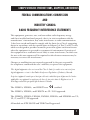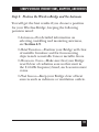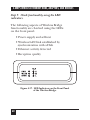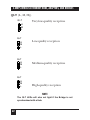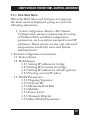
1
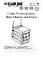
FEBRUARY 1998
LW001A LW004A
LW002A LW005A
LW003A LW007A
LW008A
LW011A
LW009A LW011AE
LW010A
LW012A
LW012AE
3-Mbps Wireless Ethernet
Hubs, Adapters, and Bridges
less
Wireet Hub
rn
Ethe
LOAD
H
M
L
PWR
INFR
ETHR
PWR
K
WLN
ETHR
PWR
K
WLN
ETHR
PWR
K
WLN
ETHR
tion
ksta
Wor apter
Ad
QLT
H
M
L
QLT
H
M
L
less
Wirege
Brid
QLT
H
M
L
CUSTOMER SUPPORT INFORMATION
Order toll-free in the U.S.: Call 877-877-BBOX (outside U.S. call 724-746-5500)
FREE technical support 24 hours a day, 7 days a week: Call 724-746-5500 or fax 724-746-0746
Mailing address: Black Box Corporation, 1000 Park Drive, Lawrence, PA 15055-1018
Web site: www.blackbox.com • E-mail: [email protected]
3-MBPS WIRELESS ETHERNET HUBS, ADAPTERS, AND BRIDGES
FEDERAL COMMUNICATIONS COMMISSION
AND
INDUSTRY CANADA
RADIO FREQUENCY INTERFERENCE STATEMENTS
This equipment generates, uses, and can radiate radio frequency energy
and if not installed and used properly, that is, in strict accordance with the
manufacturer’s instructions, may cause interference to radio communication.
It has been tested and found to comply with the limits for a Class A computing
device in accordance with the specifications in Subpart J of Part 15 of FCC rules,
which are designed to provide reasonable protection against such interference
when the equipment is operated in a commercial environment. Operation of
this equipment in a residential area is likely to cause interference, in which case
the user at his own expense will be required to take whatever measures may be
necessary to correct the interference.
Changes or modifications not expressly approved by the party responsible
for compliance could void the user’s authority to operate the equipment.
This digital apparatus does not exceed the Class A limits for radio noise emission from
digital apparatus set out in the Radio Interference Regulation of Industry Canada.
Le présent appareil numérique n’émet pas de bruits radioélectriques dépassant les limites
applicables aux appareils numériques de classe A prescrites dans le Règlement sur le
brouillage radioélectrique publié par Industrie Canada.
The LW001A, LW005A, and LW007A are
certified.
The LW001A, LW005A, and LW007A are UL 19.50 approved.
The LW002A, LW003A, LW004A, LW008A, LW009A, and LW0010A are UL,
UL/C, and TUV/GS approved.
All models are ETS 300-328 and VDE Class B approved.
1
3-MBPS WIRELESS ETHERNET HUBS, ADAPTERS, AND BRIDGES
NORMAS OFICIALES MEXICANAS (NOM)
ELECTRICAL SAFETY STATEMENT
INSTRUCCIONES DE SEGURIDAD
1. Todas las instrucciones de seguridad y operación deberán ser leídas antes
de que el aparato eléctrico sea operado.
2. Las instrucciones de seguridad y operación deberán ser guardadas para
referencia futura.
3. Todas las advertencias en el aparato eléctrico y en sus instrucciones de
operación deben ser respetadas.
4. Todas las instrucciones de operación y uso deben ser seguidas.
5. El aparato eléctrico no deberá ser usado cerca del agua—por ejemplo,
cerca de la tina de baño, lavabo, sótano mojado o cerca de una alberca,
etc..
6. El aparato eléctrico debe ser usado únicamente con carritos o pedestales
que sean recomendados por el fabricante.
7. El aparato eléctrico debe ser montado a la pared o al techo sólo como sea
recomendado por el fabricante.
8. Servicio—El usuario no debe intentar dar servicio al equipo eléctrico más
allá a lo descrito en las instrucciones de operación. Todo otro servicio
deberá ser referido a personal de servicio calificado.
9. El aparato eléctrico debe ser situado de tal manera que su posición no
interfiera su uso. La colocación del aparato eléctrico sobre una cama,
sofá, alfombra o superficie similar puede bloquea la ventilación, no se
debe colocar en libreros o gabinetes que impidan el flujo de aire por los
orificios de ventilación.
2
3-MBPS WIRELESS ETHERNET HUBS, ADAPTERS, AND BRIDGES
10. El equipo eléctrico deber ser situado fuera del alcance de fuentes de calor
como radiadores, registros de calor, estufas u otros aparatos (incluyendo
amplificadores) que producen calor.
11. El aparato eléctrico deberá ser connectado a una fuente de poder sólo del
tipo descrito en el instructivo de operación, o como se indique en el
aparato.
12. Precaución debe ser tomada de tal manera que la tierra fisica y la
polarización del equipo no sea eliminada.
13. Los cables de la fuente de poder deben ser guiados de tal manera que no
sean pisados ni pellizcados por objetos colocados sobre o contra ellos,
poniendo particular atención a los contactos y receptáculos donde salen
del aparato.
14. El equipo eléctrico debe ser limpiado únicamente de acuerdo a las
recomendaciones del fabricante.
15. En caso de existir, una antena externa deberá ser localizada lejos de las
lineas de energia.
16. El cable de corriente deberá ser desconectado del cuando el equipo no
sea usado por un largo periodo de tiempo.
17. Cuidado debe ser tomado de tal manera que objectos liquidos no sean
derramados sobre la cubierta u orificios de ventilación.
18. Servicio por personal calificado deberá ser provisto cuando:
A:
El cable de poder o el contacto ha sido dañado; u
B:
Objectos han caído o líquido ha sido derramado dentro del
aparato; o
C:
El aparato ha sido expuesto a la lluvia; o
D:
El aparato parece no operar normalmente o muestra un cambio en
su desempeño; o
E:
El aparato ha sido tirado o su cubierta ha sido dañada.
3
3-MBPS WIRELESS ETHERNET HUBS, ADAPTERS, AND BRIDGES
TRADEMARKS
Apple® is a registered trademark of Apple Computer,
Inc.
Digital™ is a trademark of Digital Equipment
Corporation.
HP® is a registered trademark of Hewlett-Packard.
IBM® is a registered trademark of International
Business Machines Corporation.
Windows® is a registered trademark of Microsoft
Corporation.
ProComm® is a registered trademark of
DATASTORM TECHNOLOGIES, INC.™
All applied-for and registered trademarks are the
property of their respective owners.
4
3-MBPS WIRELESS ETHERNET HUBS, ADAPTERS, AND BRIDGES
Contents
1. Specifications..............................................97
2. Quick-Start Setup and Operation
for the Hub.................................................14
3. Introduction ...............................................16
3.1 The 3-Mbps Wireless Ethernet
Product Line.......................................16
3.2 Features of Wireless LANs .................27
4. Setting Up the LAN ...................................29
4.1 Installing the Hub
(LW001A or LW007A) .......................29
4.2 Installing the Workstation Adapter
(LW002A or LW008A) .......................38
4.3 Installing the 4-Port Workstation
Adapter (LW003A or LW009A) ........45
4.4 Installing the Wireless Bridge
(LW004A or LW010A) .......................55
4.5 Setting Up a Basic Wireless
Ethernet Cell ......................................63
4.6 Setting Up Overlapping Cells............69
4.7 Associating with a Hub .......................71
4.8 Associating with Other Hubs..............73
4.9 Antennas..............................................74
5. Advanced Setup..........................................80
5
3-MBPS WIRELESS ETHERNET HUBS, ADAPTERS, AND BRIDGES
5.1 Accessing Advanced Setup
Functions ............................................80
5.1.1 Hub Main Menu.......................87
5.1.2 System Configuration
Menus........................................89
5.1.3 Current Station Parameters.....90
5.1.4 IP Related Items .......................91
5.1.5 WLAN Parameters....................95
5.1.6 Station Control Menu ..............105
5.2 Access Control Menu .........................108
6
3-MBPS WIRELESS ETHERNET HUBS, ADAPTERS, AND BRIDGES
1. Specifications
NOTE
All specifications apply to Hub models LW001A,
LW005A, and LW007A, Adapter models LW002A,
LW003A, LW008A, and LW009A, and Bridge models
LW004A and LW010A, unless otherwise noted.
Radio/Modem
Frequency—2.4 to 2.4835 GHz
Radio type—Spread spectrum, Frequency
Hopping
Transmission Power—10 or 100 mW
Modulation—GFSK
Data rate—1, 2, 3 Mbps
Cell size (LW001A, LW002A, LW003A, LW005A,
LW007A, LW008A, LW009A): open air—1000m
(3000 feet)
Cell size (LW001A, LW002A, LW003A, LW005A,
LW007A, LW008A, LW009A): indoor—200 m
(600 feet)
7
3-MBPS WIRELESS ETHERNET HUBS, ADAPTERS, AND BRIDGES
Range, open air (LW004A, LW010A)—Up to
7 miles (10 km)
Antenna diversity—LW001A, LW002A, LW003A,
LW005A: 2 attached antennas, 2 dBi omni;
LW007A, LW008A, LW009A: 2 detached
antennas, 2 dBi omni;
LW004A: 1 or 2 attached antennas, 2 dBi omni;
LW010A: 1 or 2 detached antennas, 2 dBi omni
Optional antennas, ordered separately (for use with
LW007A, LW008A, LW009A, and LW010A)—6 dBi
Omnidirectional Antenna (part
number LW011A); 8.5 dBi Unidirectional
Antenna (part number LW012A)
Maximum number of stations supported—256
Wireless LAN Interface
Standard—IEEE 802.11 D2
Media Access Protocol—CSMA/CA
Network Interface
LAN interface—10BASE-T
8
3-MBPS WIRELESS ETHERNET HUBS, ADAPTERS, AND BRIDGES
Standards—IEEE 802.3, IEEE 802.1d,
Transparent to network protocols (IP, IPX,
Appletalk, OSI, NetBIOS, DECnet, etc.)
LED Indicators (LW001A, LW005A, LW007A):
Power and Self-Test—PWR
Wired LAN activity—ETHR
Radio Interference—INFR
Wireless LAN load (3 LEDs)—H (High), M
(Medium), L (Low)
LED Indicators (LW002A, LW003A, LW004A, LW008A,
LW009A, LW010A):
Power and Self-Test
Wireless Link
Wired LAN activity
Wireless LAN signal quality (3 LEDs)
9
3-MBPS WIRELESS ETHERNET HUBS, ADAPTERS, AND BRIDGES
Security (LW004A, LW010A):
Encryption—802.11 compatible
Authentication—Network ID, Password
Management (LW001A, LW005A, LW007A):
SNMP agent—MIB-II, bridge MIB, Radio MIB
Wired Ethernet, serial SLIP, and wireless
management access
Software download by TFTP
Local monitor (RS-232)
Management (LW002A, LW008A):
SNMP agent—MIB-I and II, bridge MIB, Private
MIB
Wired Ethernet and wireless management access
Software downloaded by TFTP
10
3-MBPS WIRELESS ETHERNET HUBS, ADAPTERS, AND BRIDGES
Management (LW003A, LW009A):
SNMP agent—MIB-1 and II, bridge MIB, Private
MIB
Wired Ethernet, serial SLIP, and wireless
management access
Software downloaded by TFTP
Management (LW004A, LW010A):
SNMP agent—MIB-II, bridge MIB, Radio MIB
Wired Ethernet, serial SLIP, and wireless
management access
Software downloaded by TFTP
Local monitor (RS-232)
Electrical
External power supply—100-250 VAC,
autosensing
Input voltage—5 VDC, 1200mA
11
3-MBPS WIRELESS ETHERNET HUBS, ADAPTERS, AND BRIDGES
Dimensions
5.1”H x 3.4”W x 1.2”D (13 x 8.6 x 3 cm)
Weight
1 lb. (0.45 kg)
Environmental
Operating temperature—32° to 105° F (0° to
40° C)
Operating humidity—5% to 95% non-condensing
Immunity
Will maintain link under all conditions—Per
EN 50082-1
12
3-MBPS WIRELESS ETHERNET HUBS, ADAPTERS, AND BRIDGES
Approvals (LW001A, LW005A, LW007A):
UL 19.50
FCC Part 15
ETS 300-328
VDE Class B
CE
Approvals (LW002A, LW003A, LW004A, LW008A,
LW009A, LW010A):
UL, UL/C, TUV/GS
FCC Part 15
ETS 300-328
VDE Class B
13
3-MBPS WIRELESS ETHERNET HUBS, ADAPTERS, AND BRIDGES
2. Quick Start Setup and
Operation for the Hub
Use the following steps to get up and running with
your 3-Mbps Wireless Ethernet Hub. (For more
detailed procedures, see Section 4.1.)
1. Position the Hub in a high, central location,
well away from moving objects and metal
furniture.
NOTE
When using more than one Hub, make sure to define
different hopping sequences for each Access Point.
See Chapter 5.
2. Connect the power transformer to a 110/220
VAC power supply and to the DC input socket
on the Hub.
3. Connect the Hub to the Ethernet backbone
by attaching one end of a regular, uncrossed
10BASE-T cable (not supplied) to the RJ-45
port on the back panel of the Hub (marked
UTP). Attach the other end of the connector
cable to any available Ethernet hub port.
14
3-MBPS WIRELESS ETHERNET HUBS, ADAPTERS, AND BRIDGES
4. Check the function of the Hub using
the front-panel LED indicators as follows:
• PWR—Power supply
• INFR—Radio interference
• ETH—Ethernet activity
• LOAD—Number of associated stations
(Low, Medium, High)
15
3-MBPS WIRELESS ETHERNET HUBS, ADAPTERS, AND BRIDGES
3. Introduction
3.1 The 3-Mbps Wireless Ethernet Product Line
The Wireless Ethernet product line contains the
following units:
• Wireless Ethernet Hub (LW001A, LW005A,
or LW007A)
• Wireless Ethernet Workstation Adapter
(LW002A or LW008A)
• Wireless Ethernet Four-Port Workstation
Adapter (LW003A or LW009A)
• Wireless Ethernet Wireless Bridge
(LW004A or LW010A)
WIRELESS ETHERNET HUB (LW001A, LW005A, OR
LW007A)
The Wireless Ethernet Hub (LW001A) is a wireless
Hub that provides access for the wireless workstation
users into wired Ethernet LANs.
The Wireless Ethernet Hub for PCMCIA
(LW005A) is the same as the LW001A, except that
the LW005A must be used with the PCMCIA Wireless
Adapter (LW006A). Any reference in this manual to
the LW001A also applies to the LW005A.
16
3-MBPS WIRELESS ETHERNET HUBS, ADAPTERS, AND BRIDGES
The LW001A and LW007A function exactly the
same way, but the LW001A has permanently attached
antennas, and the LW007A has detachable antennas.
A third Hub, LW005A (which is covered in a separate
manual), has the same hardware as the LW007A, but
different software. It works with portable computers
equipped with the PCMCIA Wireless Adapter
(LW006A) to connect to wired Ethernet LANs.
The Hub also contains the coordinating function
that enables workstations to communicate through it
to one another inside the cell coverage area, even
though they may not be in direct line of sight.
Mobile workstations can roam from one Hub to
another that belongs to the same extended wireless
network. When Hubs are set up in such a way that
their coverage areas overlap one another, users may
roam seamlessly from cell to cell. The Workstation
Adapters “decide” when a mobile user becomes
disassociated from one Hub and associated with
another.
This process is fully transparent, requires no user
intervention, and involves no loss of data packets.
You can position multiple Hubs in locations where
you expect heavy network traffic. This will increase
the throughput capacity in the areas where you most
need it.
17
3-MBPS WIRELESS ETHERNET HUBS, ADAPTERS, AND BRIDGES
Figure 3-1. Wireless Ethernet Hub (LW001A or LW007A)
Installed on Wall.
The Wireless Ethernet Hub contains an embedded
SNMP agent that lets you manage it from the LAN
Management Information Base. Software upgrades
are downloaded by TFTP.
18
3-MBPS WIRELESS ETHERNET HUBS, ADAPTERS, AND BRIDGES
Figure 3-2. Wireless Ethernet Hub (LW001A or LW007A)
Installed on Shelf.
19
3-MBPS WIRELESS ETHERNET HUBS, ADAPTERS, AND BRIDGES
WIRELESS ETHERNET WORKSTATION ADAPTER (LW002A OR
LW008A)
The LW002A is a wireless LAN adapter that converts
any 10BASE-T Ethernet equipped computer
(including PCs, X-Terminals, Digital™, Sun, HP®,
IBM®, and Apple®), into a wireless LAN station. The
LW002A is transparent to the computer’s hardware
and software. This enables plug-and-play installation.
The LW002A and LW008A function exactly the
same way, but the LW002A has permanently attached
antennas, and the LW008A has detachable antennas.
The Workstation Adapter can communicate with
any other workstation adapters in its coverage area,
or via the Wireless Ethernet Hub to all of the
network resources such as file servers, printers and
shared databases.
The Workstation Adapter contains an embedded
SNMP agent that lets you effectively manage it from
the LAN Management Information Base. Software
upgrades are downloaded by TFTP.
20
3-MBPS WIRELESS ETHERNET HUBS, ADAPTERS, AND BRIDGES
Figure 3-3. Workstation Adapter (LW002A or LW008A).
The network stays connected while you roam
between overlapping coverage areas; plus, you get
continuous transmission and reception while moving
at high speed without losing or duplicating data
packets.
21
3-MBPS WIRELESS ETHERNET HUBS, ADAPTERS, AND BRIDGES
WIRELESS ETHERNET 4-PORT WORKSTATION ADAPTER
(LW003A OR LW009A)
The Wireless Ethernet 4-Port Workstation Adapter
(LW003A) is a wireless LAN adapter that connects a
workgroup of up to four 10BASE-T Ethernet
equipped workstations to the wireless LAN.
Workstations that can be converted by the 4-Port
Workstation Adapter into wireless LAN stations
include PCs,
X-Terminals, Digital, SUN, HP, IBM and Apple
computers. The Adapter is transparent to the
workgroup computers’ hardware and software.
The LW003A and LW009A function exactly the
same, but the LW003A has permanently attached
antennas, and the LW009A has detachable antennas.
The 4-Port Workstation Adapter lets connected
workstations communicate with other Wireless
Ethernet stations in its coverage area, or via the
Wireless Ethernet Hub (LW001A or LW007A) to all
of the network resources such as file servers, printers
and shared databases. The 4-Port Workstation
Adapter also allows highly efficient and fast wired
communication between the connected
workstations.
22
3-MBPS WIRELESS ETHERNET HUBS, ADAPTERS, AND BRIDGES
The 4-Port Workstation Adapter contains an
embedded SNMP agent and software downloading
capabilities that let you manage it from the LAN
Management Information Base.
Figure 3-4. 4-Port Workstation Adapter (LW003A or LW009A).
23
3-MBPS WIRELESS ETHERNET HUBS, ADAPTERS, AND BRIDGES
WIRELESS BRIDGE (LW004A OR LW010A)
The Wireless Bridge (LW004A) is a high-speed, widerange wireless LAN bridge that provides connectivity
to remote Ethernet networks.
The LW004A and LW010A function exactly the
same way, but the LW004A has permanently attached
antennas, and the LW010A has detachable antennas.
The LW004A communicates with the Wireless
Ethernet Hubs (LW001A) of the remote LANs, and
the LW010A communicates with the Wireless
Ethernet Hub (LW007A) of the remote LANs. This
effectively creates an extended wireless network
spanning sites situated up to 7 miles apart. In this
way a central Ethernet LAN may be connected with
one or more branch office LANs.
The Wireless Bridge also allows connectivity
between a wireless LAN and individual workstations
or workgroups located outside the LAN.
WIRELESS ETHERNET HUB FOR PCMCIA ADAPTER
(LW005A)
The LW005A Hub, which is covered in detail in a
separate user manual, is physically identical to the
LW007A, but has different software. It works with
portable computers equipped with the PCMCIA
Wireless Adapter (LW006A) to connect to wired
Ethernet LANs.
24
3-MBPS WIRELESS ETHERNET HUBS, ADAPTERS, AND BRIDGES
PCMCIA WIRELESS ADAPTER (LW006A)
The LW006A adapter, which is covered in detail in a
separate user manual, gives the portable computer
user complete mobility, allowing seamless roaming
throughout the wireless LAN campus.
The PCMCIA Wireless Adapter converts any
portable computer (notebook, laptop, pen-based,
etc.) containing a PCMCIA Release 2.1 Type II slot
into a wireless LAN station.
The LW006A adapter can communicate with any
other wireless station in its coverage area, and can
access all of the network resources like file servers,
printers and shared databases via the Wireless
Ethernet Hub (LW005A, covered in a separate
manual).
The network stays connected while you roam
between overlapping coverage areas; plus, you get
continuous transmission and reception while moving
at high speed without losing or duplicating data
packets.
25
3-MBPS WIRELESS ETHERNET HUBS, ADAPTERS, AND BRIDGES
Figure 3-5. PCMCIA Wireless Adapter (LW006A).
WIRELESS BRIDGE FOR PCMCIA ADAPTER (LW005A)
The Wireless Bridge for PCMCIA Adapter is covered
in a separate user manual.
OPTIONAL ANTENNAS (LW011A AND LW012A)
The 6 dBi Omnidirectional Antenna (LW011A) and
the Unidirectional Antenna (LW012A) work only
with the LW005A and LW007A Hubs, LW008A and
LW009A Adapters, and LW010A Bridge.
26
3-MBPS WIRELESS ETHERNET HUBS, ADAPTERS, AND BRIDGES
3.2 Features of Wireless Ethernet LANs
• Saves cabling costs—The wireless Ethernet LAN
saves you cabling costs that can amount to up
to 40% of your LAN installation cost.
• Plug-and-play installation—No additional
software or hardware installation is required.
After connecting the units to the power supply
and connecting the Hubs to the wired LAN,
your Wireless Ethernet system is ready to
operate.
• Flexibility—The wireless Ethernet LAN provides
an effective communication solution for:
- Campus environments
- Temporary or leased offices
- Trade shows
- Manufacturing environments
- Hospital applications
- Harbors and airports
- Buildings that are difficult to wire
- Points of sale
27
3-MBPS WIRELESS ETHERNET HUBS, ADAPTERS, AND BRIDGES
• Workstation mobility—Notebook and pen-based
computer users can roam throughout the
Wireless Ethernet campus. As long as the
coverage areas are overlapping this mobility is
seamless. Users maintain their network
connection while roaming from cell to cell.
• Quickly extends wired LAN—A Wireless Ethernet
LAN cell gives instant add-on capability to your
wired LAN for temporary or permanent
expansion.
• Technical Advantages
- High data rate of 3 Mbps, with automatic
fallback to 2 and 1 Mbps.
- License-free use (2.4GHz ISM band, FHSS)
- 15 Mbps aggregate throughput in the same
coverage area by multiple Hubs.
- Antenna diversity and DSP modem ensure
robust communication.
- Software, including modem module, upgraded
by downloading.
- Security is provided by Spread Spectrum
Frequency Hopping and Network ID.
- Simple network management support (SNMP).
28
3-MBPS WIRELESS ETHERNET HUBS, ADAPTERS, AND BRIDGES
4. Setting Up the LAN
4.1 Installing the Hub
Follow these steps:
• Check the package contents.
• Choose the best location to place the Hub.
• Connect to the power supply.
• Connect to the Ethernet backbone.
• Check functionality using the LED indicators.
Step 1: Check to make sure the package contains the
components you will need.
The package you received should contain the
following components:
• The Wireless Ethernet Hub (LW001A or
LW007A), complete with two omnidirectional
antennas.
• A 5-VDC power-supply transformer.
29
3-MBPS WIRELESS ETHERNET HUBS, ADAPTERS, AND BRIDGES
• A monitor connector cable. (This is for
connecting the Hub and the Workstation
Adapter [LW002A, LW003A, LW008A, or
LW009A] to a monitor for performing the
advanced setup functions described in
Chapter 5).
• This user’s manual.
If anything is missing from your package,
please contact your dealer.
Step 2: Position the Hub
The Wireless Ethernet LAN products are robust
trouble-free units, designed to operate efficiently
under a wide range of conditions. The following
guidelines are recommendations to help you
position the Hubs to ensure optimum coverage and
operation of the Wireless Ethernet LAN.
Height
Install the Hub at least 4.9 ft. (1.5 m) above the
floor, clearing any high office partitions or tall pieces
of furniture in the coverage area. You can place the
Hub on a high shelf, or attach it to the ceiling or a
wall using a mounting bracket (not included).
30
3-MBPS WIRELESS ETHERNET HUBS, ADAPTERS, AND BRIDGES
Antennas
Make sure the antennas are extended vertically in
relation to the floor.
Central Location
Install the Hub in a central location in the coverage
area you intend to include in the cell. Good
positions are:
• At the center of a large room.
• At the center of a corridor.
• At the intersections of two corridors.
Many modern buildings have metallic partitions.
We recommend that you install the Hubs in the
corridor ceilings. The radio waves propagated by the
Wireless Ethernet LAN may be reflected along the
metal partitions and enter the offices through the
doors or glass sections.
Metal Furniture
Position the Hubs well clear of metallic furniture
and far from moving objects such as metallic fans
or metallic doors.
31
3-MBPS WIRELESS ETHERNET HUBS, ADAPTERS, AND BRIDGES
Heat Sources
Keep the Hub well away from sources of heat,
such as radiators, air-conditioners etc.
Microwave Ovens
Place the Hubs well clear of radiation sources
that emit in the 2.4 GHz frequency band,
such as microwave ovens.
32
3-MBPS WIRELESS ETHERNET HUBS, ADAPTERS, AND BRIDGES
Step 3: Connect the Hub to the Power Supply
• Connect the supplied power transformer to
an external power supply at 110 or 220 VAC.
• The unit operates on a power input of 5 VDC
(1200 mA).
Figure 4-1. Connecting to Power Supply.
33
3-MBPS WIRELESS ETHERNET HUBS, ADAPTERS, AND BRIDGES
Step 4: Connect the Hub to the Ethernet Backbone
Attach one end of a regular (uncrossed) Ethernet
connector cable (not supplied) to the RJ-45 port on
the back panel of the Hub (marked UTP).
Attach the other end of the connector cable to any
available Ethernet Hub outlet.
Figure 4-2. Hub Back Panel.
34
3-MBPS WIRELESS ETHERNET HUBS, ADAPTERS, AND BRIDGES
Figure 4-3. Connecting the Hub to the Ethernet Backbone.
Step 5: Check Hub Functionality Using LED Indicators
The following aspects of Hub functionality are
checked using the LEDs on the front panel.
• Power supply
• Radio interference
• Ethernet activity
• LAN load
35
3-MBPS WIRELESS ETHERNET HUBS, ADAPTERS, AND BRIDGES
Figure 4-4. Front-Panel LED Indicators.
PWR (Power supply; Power-on test)
Off—During power-on
Blinks—After failed power-on
On—After successful power-on
INFR (Radio interference)
Off—No interference
Blinks—Interference present
ETHR (Ethernet activity)
Off—No activity on the Ethernet Port
Blinks—Activity on the Ethernet Port
36
3-MBPS WIRELESS ETHERNET HUBS, ADAPTERS, AND BRIDGES
LOAD (L,M,H) (No. of associated stations)
Q LT
H
M
L
No stations
QLT
H
M
L
QLT
H
M
L
QLT
H
M
L
1-4 stations
5-8 stations
9 or more stations
37
3-MBPS WIRELESS ETHERNET HUBS, ADAPTERS, AND BRIDGES
Verifying the Ethernet Connection
Once the Hub is connected to an Ethernet outlet,
the ETHR LED on the front panel will blink when
sensing LAN traffic, thus verifying the Ethernet
connection.
4.2 Installing the Workstation Adapter (LW002A or LW008A)
Installing the Adapter is a plug-and-play procedure.
All you need to get up and running is to connect the
power supply to the Adapter and to connect the
Adapter to your computer.
You can make sure the Adapter is fully operational
by checking the LED indicators as described in Step
5 on page 44.
To complete the installation process you will need
one Ethernet connector cable with an RJ-45
connector at each end.
Step 1: Check to make sure the package contains the
components you will need.
The package you received should contain the
following components:
38
3-MBPS WIRELESS ETHERNET HUBS, ADAPTERS, AND BRIDGES
• Workstation Adapter (LW002A or LW008A),
complete with two omnidirectional antennas.
• 5 VDC power supply transformer.
• This User’s Manual.
Figure 4-5. Back Panel of the Adapter.
Step 2: Connect the Adapter to the power supply.
• Connect the power transformer to an external
power outlet at 110 or 220 VAC.
• Connect the output jack of the power
transformer to the DC input socket on the back
panel of the Adapter.
The unit operates on a power input of 5 VDC
(1200mA).
39
3-MBPS WIRELESS ETHERNET HUBS, ADAPTERS, AND BRIDGES
Figure 4-6. Connecting to the Power Supply.
40
3-MBPS WIRELESS ETHERNET HUBS, ADAPTERS, AND BRIDGES
Step 3: Connect the Adapter to your computer or
workstation.
• Connect the RJ-45 connector at one end of a
regular (uncrossed) Ethernet cable, to the UTP
port on the back panel of the Adapter.
• Connect the RJ-45 connector on the other end
of the Ethernet cable to the input socket of the
Ethernet Network Interface Card on the back
panel of your computer.
Figure 4-7. Connecting the Adapter to a Workstation.
41
3-MBPS WIRELESS ETHERNET HUBS, ADAPTERS, AND BRIDGES
Step 4: Position Your Adapter
You will get the best results if you choose a position
for your Adapter, keeping the following points in
mind:
• Metal Furniture—Position your Adapter well
clear of metallic furniture and far from moving
objects such as metallic fans or metallic doors.
• Microwave Ovens—Make sure that your Adapter
is well clear of radiation sources that emit in
the 2.4 GHz frequency band, such as microwave
ovens.
• Antennas—Make sure the antennas are
extended vertically in relation to the floor.
• Heat Sources—Keep your Adapter clear of heat
sources such as radiators or ventilation outlets.
Step 5: Check functionality using the LED
indicators.
LEDs on the front panel of the Adapter indicate the
following:
• Power supply and self-test
• Wireless LAN link established by
synchronization with an Hub.
42
3-MBPS WIRELESS ETHERNET HUBS, ADAPTERS, AND BRIDGES
• Ethernet activity detected.
• Reception quality.
Figure 4-8. Front-Panel LED Indicators.
Front-Panel LED indicators
PWR (Power supply; Power-on test):
Off—During power-on
Blinks—After failed power-on
On—After successful power-on
WLNK
Off—Scanning for Hub
On—Synchronized with Hub
ETHR
Off—No activity on the Ethernet port
Blinks—Activity on the Ethernet port
43
3-MBPS WIRELESS ETHERNET HUBS, ADAPTERS, AND BRIDGES
QLT (L, M, H))
Q LT
H
M
L
QLT
H
M
L
QLT
H
M
L
Very-low-quality reception
Low-quality reception
Medium-quality reception
QLT
H
M
L
High-quality reception
NOTE
The QLT LEDs will also not light if the workstation is not
synchronized with a Hub.
44
3-MBPS WIRELESS ETHERNET HUBS, ADAPTERS, AND BRIDGES
4.3 Installing the 4-Port Workstation Adapter (LW003A or
LW009A)
The 4-Port Workstation Adapter (LW003A or
LW009A) is a plug-and-play installation. All you
need to get up and running is to connect the power
supply to the Adapter and to connect the Adapter
to your computer.
You can make sure the Adapter is fully operational
by checking the LED indicators as described in Step
5 on page 53.
To complete the installation process, you will
need one Ethernet connector cable with an RJ-45
connector at each end, for each workstation to
be connected.
Step 1: Check to make sure the package contains
the components you will need.
The package you received should contain
the following components:
• 4-Port Workstation Adapter
(LW003A or LW009A)
• 5 VDC power supply transformer
• This User’s Manual
45
3-MBPS WIRELESS ETHERNET HUBS, ADAPTERS, AND BRIDGES
Figure 4-9. Front and Back Panels of the 4-Port Workstation
Adapter.
46
3-MBPS WIRELESS ETHERNET HUBS, ADAPTERS, AND BRIDGES
Step 2: Connect the Adapter to the power supply.
• Connect the power transformer to an external
power outlet at 110 or 220 VAC.
• Connect the output jack of the power
transformer to the DC input socket on the side
panel of the Adapter.
The unit operates on a power input of 5 VDC
(1200 mA).
Figure 4-10. Connecting to the Power Supply.
47
3-MBPS WIRELESS ETHERNET HUBS, ADAPTERS, AND BRIDGES
Step 3: Connect the 4-Port Adapter to your computer or
workstation.
• Connect the RJ-45 connector at one end of a
regular (uncrossed) Ethernet cable, to any
available port on the front panel of the
Adapter.
• Connect the RJ-45 connector on the other end
of the Ethernet cable to the input socket of the
Ethernet Network Interface Card on the back
panel of your computer.
48
3-MBPS WIRELESS ETHERNET HUBS, ADAPTERS, AND BRIDGES
Figure 4-11. Connecting the Adapter to a Workstation.
49
3-MBPS WIRELESS ETHERNET HUBS, ADAPTERS, AND BRIDGES
Step 4: Position the 4-Port Adapter
You will get the best results if you keep the following
points in mind when you choose a position for your
adapter:
• Metal Furniture—Position your Adapter well
clear of metallic furniture and far from moving
objects such as metallic fans or metallic doors.
• Microwave Ovens—Make sure that your Adapter
is well clear of radiation sources that emit in
the 2.4 GHz frequency band, such as microwave
ovens.
• Antennas—Make sure the antennas are
extended vertically in relation to the floor.
• Heat Sources—Keep your Adapter clear of heat
sources such as radiators or ventilation outlets.
• Fan—The 4-Port Workstation Adapter has a
cooling fan mounted on the back panel. Keep
this side of the unit clear of any obstacles that
might block adequate ventilation.
50
3-MBPS WIRELESS ETHERNET HUBS, ADAPTERS, AND BRIDGES
Step 5: Check functionality using the LED
indicators.
LEDs on the front and back panels of the Adapter
indicate the following:
Front-panel LED indicators:
• Workstation connected.
• Ethernet activity on each of the four ports.
Front-panel LEDs
Figure 4-12. LED Indicators on the Front Panel of the 4-Port
Workstation Adapter.
51
3-MBPS WIRELESS ETHERNET HUBS, ADAPTERS, AND BRIDGES
Back-panel LED indicators:
• Power supply and self-test.
• Wireless LAN link established by
synchronization with a Hub.
• Ethernet activity detected.
• Reception quality.
Figure 4-13. Indicators on the Back Panel of the 4-Port
Workstation Adapter.
52
3-MBPS WIRELESS ETHERNET HUBS, ADAPTERS, AND BRIDGES
PWR (Power supply; Power-on test):
Off—During power-on
Blinks—After failed power-on
On—After successful power-on
WLNK
Off—Scanning for Hub
On—Synchronized with Hub
ETHR
Off—No activity on the Ethernet port
Blinks—Activity on the Ethernet port
53
3-MBPS WIRELESS ETHERNET HUBS, ADAPTERS, AND BRIDGES
QLT (L, M, H))
Q LT
Very-low-quality reception
H
M
L
QLT
H
M
L
QLT
H
M
L
Low-quality reception
Medium-quality reception
QLT
H
M
L
High-quality reception
NOTE
The QLT LEDs will also not light if the workstation is not
synchronized with a Hub.
54
3-MBPS WIRELESS ETHERNET HUBS, ADAPTERS, AND BRIDGES
4.4 Installing the Wireless Bridge (LW004A or LW010A)
The Wireless Bridge (LW004A or LW010A) is a plugand-play installation. All you need to get up and
running is to connect the power supply to the Bridge
and to connect the Bridge directly to the Hub or to
any available outlet of the Ethernet LAN.
You can make sure the Wireless Bridge is fully
operational by checking the LED indicators as
described in Step 5 on page 62.
To complete the installation process, you will need
a 10BASE-T Ethernet cable with an RJ-45 connector
at each end.
Step 1: Check to make sure the package contains the
components you will need.
The package you received should contain the
following components:
• Wireless Bridge (LW004A or LW010A)
• 5-VDC power-supply transformer
• This User’s Manual
55
3-MBPS WIRELESS ETHERNET HUBS, ADAPTERS, AND BRIDGES
Figure 4-14. Front Panel of the Wireless Bridge.
Step 2: Connect the Wireless Bridge to the power supply.
• Connect the power transformer to an external
power outlet at 110 or 220 VAC.
• Connect the output jack of the power
transformer to the DC input socket on the back
panel of the Wireless Bridge.
The unit operates on a power input of 5 VDC
(1200 mA).
56
3-MBPS WIRELESS ETHERNET HUBS, ADAPTERS, AND BRIDGES
Figure 4-15. Connecting to the Power Supply.
Step 3: Connect the Wireless Bridge to the Hub or to any
available outlet of the Ethernet LAN.
• Connect the RJ-45 connector at one end of a
regular (uncrossed) Ethernet cable, to the UTP
port on the back panel of the Bridge.
57
3-MBPS WIRELESS ETHERNET HUBS, ADAPTERS, AND BRIDGES
• Connect the RJ-45 connector on the other end
of the Ethernet cable to the Ethernet Hub or
to any available Ethernet outlet.
Figure 4-16. Connecting the Wireless Bridge
to an Ethernet Hub or Outlet.
58
3-MBPS WIRELESS ETHERNET HUBS, ADAPTERS, AND BRIDGES
Step 4: Position the Wireless Bridge and the Antennas
You will get the best results if you choose a position
for your Wireless Bridge, keeping the following
points in mind:
• Antennas—For detailed information on
selecting, installing and mounting antennas,
see Section 4.9.
• Metal Furniture—Position your Bridge well clear
of metallic furniture and far from moving
objects such as metallic fans or metallic doors.
• Microwave Ovens—Make sure that your Bridge
is well clear of radiation sources that emit in
the 2.4 GHz frequency band, such as microwave
ovens.
• Heat Sources—Keep your Bridge clear of heat
sources such as radiators or ventilation outlets.
59
3-MBPS WIRELESS ETHERNET HUBS, ADAPTERS, AND BRIDGES
Step 5: Check functionality using the LED
indicators.
The following aspects of Wireless Bridge
functionality are checked using the LEDs
on the front panel.
• Power supply and self-test
• Wireless LAN link established by
synchronization with a Hub
• Ethernet activity detected
• Reception quality
Figure 4-17. LED Indicators on the Front Panel
of the Wireless Bridge.
60
3-MBPS WIRELESS ETHERNET HUBS, ADAPTERS, AND BRIDGES
Front-panel LED indicators:
PWR (Power supply; Power-on test):
Off—During power-on
Blinks—After failed power-on
On—After successful power-on
WLNK
Off—Scanning for Hub
On—Synchronized with Hub
ETHR
Off—No activity on the Ethernet port
Blinks—Activity on the Ethernet port
61
3-MBPS WIRELESS ETHERNET HUBS, ADAPTERS, AND BRIDGES
QLT (L, M, H))
Q LT
Very-low-quality reception
H
M
L
QLT
H
M
L
QLT
H
M
L
Low-quality reception
Medium-quality reception
QLT
H
M
L
High-quality reception
NOTE
The QLT LEDs will also not light if the Bridge is not
synchronized with a Hub.
62
3-MBPS WIRELESS ETHERNET HUBS, ADAPTERS, AND BRIDGES
4.5 Setting Up a Basic Wireless Ethernet Cell
A basic Wireless Ethernet cell consists of an Hub and
the wireless workstations associated with it. You can
convert most workstations (PCs,
X-Terminals, Apple, Digital, Sun, HP, IBM and
others) that are equipped with an Ethernet network
interface card to wireless workstations by simply
connecting a Workstation Adapter (LW002A or
LW008A).
NOTE
Installation procedures for the Workstation Adapter are
described in Section 4.3.
63
3-MBPS WIRELESS ETHERNET HUBS, ADAPTERS, AND BRIDGES
Figure 4-18. Basic Wireless Ethernet Cell.
To set up a basic Wireless Ethernet cell:
1. Place the Hub as high as possible on a wall
or on a high stand, or attach it to the ceiling
with a mounting bracket.
2. Follow the installation procedures described
in Section 4.2.
3. Install a Workstation Adapter on the first
workstation you wish to convert to a wireless
workstation.
64
3-MBPS WIRELESS ETHERNET HUBS, ADAPTERS, AND BRIDGES
Use the LED Indicators on the front panel of
the Workstation Adapter to check the received
signal quality. The signal quality should be in
the high to medium range.
4. Make any adjustments necessary. For example:
• Adjust the antenna.
• Adjust the location of the Workstation Adapter.
• Adjust the location of the Hub.
5. Install the next Workstation Adapter
(LW002A) or 4-Port Workstation Adapter
(LW003A) and verify the Received Signal
Strengths.
Area-Coverage Considerations
When planning the coverage areas of Wireless
Ethernet cells, consider the following factors:
• Construction Materials—The area of a cell is
influenced by the construction materials of
the walls, the partitions, ceilings, and floors,
and by the furnishings of the cell:
- Metallic objects reflect the radio signals,
but do not let the signals pass through them.
65
3-MBPS WIRELESS ETHERNET HUBS, ADAPTERS, AND BRIDGES
- Wood, glass plastic and bricks reflect part of
the radio signals and allow part of the signals
to pass through them.
- Water and objects containing a lot of moisture
absorb a large part of the radio signals.
Figure 4-19. Wireless Ethernet LAN in Typical Office
Environment.
66
3-MBPS WIRELESS ETHERNET HUBS, ADAPTERS, AND BRIDGES
• Distance Between Cells—The distance between
the cells varies according to the floor plan of
the building and the nature of the indoor
environment. Five general categories of areas
can be classified:
1. Open Indoor Areas—Open office areas with no
partitioning and no obstacles between the Hub
and the Wireless Ethernet workstation.
Suggested maximum distance between Hub
and workstation: 150 m (500 ft.)
With high-gain antennas: 250 m (800 ft.)
2. Semi-open Indoor Areas—An open-plan office
divided into cubicles. Factory floor areas,
warehouses, etc.
Suggested maximum distance between Hub
and workstation: 80 m (260 ft.)
67
3-MBPS WIRELESS ETHERNET HUBS, ADAPTERS, AND BRIDGES
Figure 4-20. Overlapping Wireless Ethernet Cells in Office
Environment.
3. Closed Indoor Areas—A floor divided into
Wireless Ethernet individual offices by concrete
or masonry walls, or a house.
Suggested maximum distance between Hub
and workstation: 50 m (160 ft.)
4. Open Outdoor Areas—Open outdoor areas with
unobstructed line-of-sight between the Hub
and the Wireless Ethernet workstation.
68
3-MBPS WIRELESS ETHERNET HUBS, ADAPTERS, AND BRIDGES
Suggested maximum distance between Hub
and workstation: 1000 m (3200 ft.)
With high-gain antennas: 1500 m (5000 ft.)
5. Obstructed Outdoor Areas—Outdoor areas with
obstructed line-of-sight between the Hub and
the Wireless Ethernet workstation.
Suggested maximum distance between Hub
and workstation: 500 m (1600 ft.)
With high-gain antennas: 800 m (2500 ft.)
4.6 Setting up Overlapping Wireless Ethernet Cells
When two adjacent Hubs are positioned close
enough to each other, a wireless Ethernet part of
the coverage area of Hub #1 will overlap the
coverage area of Hub #2. This overlap area has two
important attributes:
1. Any workstation situated in the overlapping
area can communicate with both Hub #1 and
Hub #2.
2. Any workstation can move seamlessly between
the overlapping coverage areas without losing
its network connection. This attribute is called
Seamless Roaming.
69
3-MBPS WIRELESS ETHERNET HUBS, ADAPTERS, AND BRIDGES
To set up two overlapping Wireless Ethernet cells:
1. Install the first Hub wireless Ethernet as high
as possible on a wall, on a high stand, or
attached to the ceiling, using the steps
described in Section 4.1.
2. Install the second Hub so that the two are
closer together than the distance described
under “Distance Between Cells” on page 38.
Adjusting this distance will result in a larger or
smaller overlap area.
3. Set the hopping sequence of the second Hub
so that each Hub has its own different hopping
sequence. For more information, refer to
Hopping Sequence in Section 5.1.5.
4. Set up a wireless workstation at a point
approximately equidistant from the two Hubs
using the procedures described in Section 4.2.
5. Temporarily disconnect the second Hub from
the power supply. Verify reception of radio
signals from the first Hub. Use the LED
Indicators on the front panel of the
Workstation Adapter to check the received
signal strength. The signal strength should be
in the high to medium range.
70
3-MBPS WIRELESS ETHERNET HUBS, ADAPTERS, AND BRIDGES
6. Temporarily disconnect the first Hub from
the power supply. Verify a high to medium
received radio signal from the second Hub.
7. Adjust the distance between the Hubs if
necessary.
The two coverage areas are now overlapping.
8. Continue setting up overlapping cells until
the required area is covered.
NOTE
Hubs transmit signals (management frames) all the
time, with or without an Ethernet connection.
4.7 Associating with a Hub
After installation, your Adapter or Bridge will
automatically begin scanning for a Wireless Hub in
the area. Once a Hub is located, the Adapter or
Bridge will synchronize itself to the frequencies
being used, and establish association with the Hub.
The Hub, together with all the Workstation
Adapters associated with it, constitute a basic
Wireless Ethernet cell.
71
3-MBPS WIRELESS ETHERNET HUBS, ADAPTERS, AND BRIDGES
Figure 4-21. Basic Wireless Ethernet Cell.
Once the Adapters establish association, you can
communicate with all the other wireless stations in
the cell and via the Hub’s Ethernet connection, with
all the network facilities.
Once the Bridge establishes association, the Hub
starts forwarding data packets to the wireless LANs
connected to the Wireless Bridge.
72
3-MBPS WIRELESS ETHERNET HUBS, ADAPTERS, AND BRIDGES
4.8 Associating with Other Hubs
When two or more adjacent Hubs are positioned
close enough to each other, a part of the coverage
area of the Hubs will overlap. In high-traffic-density
areas, Hubs are sometimes positioned so that all of
their coverage areas overlap. A workstation situated
in an overlapping coverage area can associate with
any one of the covering Hubs.
The process of selecting with which Hub to
associate is performed automatically by the Adapter.
However, if your workstation is located within the
coverage area of more than one Hub and your
reception quality is low, you may get better reception
if you move your station to a slightly different
location. This takes advantage of a clearer or less
busy connection to another Hub.
73
3-MBPS WIRELESS ETHERNET HUBS, ADAPTERS, AND BRIDGES
Figure 4-22. Associating with Different Hubs.
4.9 Antennas
The Wireless Hub, Workstation Adapter, 4-Port
Workstation Adapter, and Wireless Bridge are each
available in two models that are identical except for
their antennas.
The Wireless Hub (LW001A), Workstation Adapter
(LW002A), 4-Port Workstation Adapter (LW003A),
and Wireless Bridge (LW004A) are all supplied with
two integral 2 dBi omnidirectional antennas. These
antennas are intended for indoor installations with
short to medium distances between sites.
74
3-MBPS WIRELESS ETHERNET HUBS, ADAPTERS, AND BRIDGES
The Wireless Hub (LW007A), Workstation Adapter
(LW008A), 4-Port Workstation Adapter (LW009A),
and Wireless Bridge (LW010A) are all supplied with
two customized female connectors for use with the
external antennas, which you must order separately.
• 6 dBi Omnidirectional Antenna (LW011A for
use in the USA; LW011AE for use in Europe)
• 8.5 dBi Unidirectional Antenna (LW012A for
use in the USA; LW012AE for use in Europe)
The LW011A and the LW012A each include a
single antenna. This receive/transmit antenna is
suitable for all indoor applications as well as for most
outdoor short- to medium-range ground-level
applications where antenna diversity is required.
Both are supplied complete with cables for either
USA or Europe.
6 DBI OMNI-DIRECTIONAL ANTENNA (LW011A OR
LW011AE)
The 6 dBi antenna is intended for indoor or outdoor
installation with longer distances between sites. This
includes an omni-directional 6 dBi transmit/receive
antenna along with the appropriate cables and
connectors.
75
3-MBPS WIRELESS ETHERNET HUBS, ADAPTERS, AND BRIDGES
USA (LW011A)
5 meters RG-214 cable complete with assembled
sections and connectors:
• SMA male connector on one end connects to
the LW007A, LW008A, LW009A, or LW010A.
• N-type connector on other end.
Figure 4-23. One LW011A 6 dBi omnidirectional antenna
connected to an LW010A external antenna port.
76
3-MBPS WIRELESS ETHERNET HUBS, ADAPTERS, AND BRIDGES
Europe (LW011AE)
3 meters RG-58 cable complete with assembled
connectors:
• SMA male connector on one end connects to
the LW007A, LW008A, LW009A, or LW010A.
• N-type male connector on the other end
connects to antenna.
8.5 DBI UNIDIRECTIONAL ANTENNA (LW012A OR
LW012AE)
The 8.5 dBi Unidirectional Antenna (LW012A) has a
wide beam width (75 degrees horizontal, 50 degrees
vertical) and is intended for both indoor and
outdoor installations for short to medium distances
between sites. This includes one transmit/receive
8.5 dBi directional antenna together with the
appropriate cables and connectors.
USA (LW012A)
5 meters RG-58/U cable complete with assembled
sections and connectors:
• SMA male connector on one end connects to
the LW007A, LW008A, LW009A, or LW010A.
77
3-MBPS WIRELESS ETHERNET HUBS, ADAPTERS, AND BRIDGES
• SMA male connector on the other end
connects to antenna.
Figure 4-24. One LW012A 8.5 dBi unidirectional antenna
connected to an LW010A external antenna port.
Europe (LW011AE)
6 meters RG-58 cable complete with assembled
connectors:
• SMA male connector on one end connects to
the LW007A, LW008A, LW009A, or LW010A.
78
3-MBPS WIRELESS ETHERNET HUBS, ADAPTERS, AND BRIDGES
• SMA male connector on the other end
connects to antenna.
• Range: 900 m
PROFESSIONAL INSTALLERS ONLY
Detached antennas, whether installed indoors or out,
are to be installed ONLY by experienced antenna
installers who are familiar with local buildings and
safety codes, and wherever necessary are licensed by
appropriate government regulators.
EXTENSION CABLES
The cables supplied with the antenna sets are
generally sufficient for most window or wall antenna
installations.
Extension cables of 5, 10, 15, and 20 meters are
available. Call for technical support for more
information.
79
3-MBPS WIRELESS ETHERNET HUBS, ADAPTERS, AND BRIDGES
5. Advanced Setup
5.1 Accessing Advanced Setup Functions
The Wireless Ethernet product line has been
designed as a plug-and-play solution, and will operate
without any user intervention. However, you can
change some of the default parameters to get
additional functionality. There are two ways to set
the parameters and/or the monitoring status of the
station:
1. Using an SNMP Management Information
Base.
2. Using a local monitor.
SNMP Manager
The Wireless Ethernet Hubs and Station Adapters
contain an embedded SNMP agent. The advanced
setup functions described on the following pages can
also be accessed from the Ethernet Management
Information Base using the SNMP application.
80
3-MBPS WIRELESS ETHERNET HUBS, ADAPTERS, AND BRIDGES
Local Monitor
The local monitor allows you to access the Hub
parameters from an ASCII ANSI terminal, or a PC,
using a terminal-emulation program such as the
Windows® Terminal or ProComm®.
You can access the advanced setup functions by
connecting a terminal to the back panel of the Hub.
Figure 5-1. Connecting Terminal Cable to COM Port
with a 9-Pin Connector.
81
3-MBPS WIRELESS ETHERNET HUBS, ADAPTERS, AND BRIDGES
Figure 5-2. Connecting Terminal Cable to COM Port with a 25-Pin
Connector.
82
3-MBPS WIRELESS ETHERNET HUBS, ADAPTERS, AND BRIDGES
To access the advanced setup functions with a local
monitor:
You can access the advanced setup functions using
an ASCII ANSI terminal or a PC capable of
emulating an ASCII ANSI terminal using the
following settings:
Baud rate
Data bits
Stop bits
Parity
Flow control
Connector
9600
8
1
None
None
Available Com port
The following procedure uses the Windows
Terminal emulation program as an example.
1. Connect the RS-232 3-pin connector at one
end of the monitor cable to the MON port on
the back panel of the Hub.
2. Connect the other end of the cable to a serial
port of a PC (COM Port); see
Figures 5-1 and 5-2.
3. Open Windows.
4. Double-click on the Terminal icon in the
Windows Program Manager’s Accessories
group.
83
3-MBPS WIRELESS ETHERNET HUBS, ADAPTERS, AND BRIDGES
The Terminal screen appears.
Figure 5-3. Terminal Icon in Windows Program Manager.
84
3-MBPS WIRELESS ETHERNET HUBS, ADAPTERS, AND BRIDGES
5. Select Communication from the Setup menu.
The communication dialog box opens.
Figure 5-4. Windows Terminal Communication Dialog Box.
85
3-MBPS WIRELESS ETHERNET HUBS, ADAPTERS, AND BRIDGES
6. Select the following settings:
Baud rate
Data bits
Stop bits
Parity
Flow control
Connector
9600
8
1
None
None
Available Com port
7. Click OK. The Hub Advanced Setup Main
Menu opens.
Figure 5-5. Terminal Screen Showing Hub Main Menu and System
Configuration Menu.
86
3-MBPS WIRELESS ETHERNET HUBS, ADAPTERS, AND BRIDGES
5.1.1 HUB MAIN MENU
When the Hub Advanced Setup screen appears,
the main menu is displayed, giving access to the
following sub-menus:
1. System Configuration Menus—The System
Configuration menus contain items for setup
of Wireless Ethernet Hub configuration
parameters, such as station parameters and IP
addresses. These menus are the only advanced
setup menus needed by users and System
Administrators.
1. System Configuration sub-menus
1.1 .Station Status
1.2 IP Addresses
1.2.1 Setting IP address for bridge
1.2.2 Setting IP net mask for bridge
1.2.3 Setting IP address for default gateway
1.2.4 Viewing current IP values
1.3 WLAN Parameters
1.3.1 Hopping Sequence
1.3.2 Network ID
1.3.3 Maximum Data Rate
1.3.4 Mobility
1.3.5 Power Level
1.3.6 Transmit Diversity
1.3.S Show WLAN Parameters
87
3-MBPS WIRELESS ETHERNET HUBS, ADAPTERS, AND BRIDGES
1.4 Station Control Menu
1.4.1 System Reset
1.4.2 Set Factory Defaults
1.4.3 Enable AppleTalk Tunneling
1.4.4 Positive Bridging
2. Maintenance Menus—These menus, which
contain advanced system functionality and
troubleshooting functions, are for technical
support personnel only.
3. Testing Menus—Items relating to packet
transmission statistics, radio and modem
parameters and tests. These tests are performed
by technical-support personnel only.
4. Access Control Menus—The Access Control
menus let the Network Administrator limit
access to the Advanced Setup menus to users in
who have the current Password.
88
3-MBPS WIRELESS ETHERNET HUBS, ADAPTERS, AND BRIDGES
5.1.2 SYSTEM CONFIGURATION MENUS
You can access all the items needed to configure
your Wireless Ethernet Hub from the System
Configuration menu.
To access the System Configuration menu:
• From the Main menu, type 1. The System
Configuration menu appears.
Use the following procedures to make selections
from the System Configuration menus.
To make selections from the menus:
1. Select one of the items from the menu.
Type 1 to select the Station Status menu.
Type 2 to select the IP Addresses menu.
Type 3 to select the WLAN Parameters menu.
Type 4 to select the Station Control menu.
The selected sub-menu appears.
2. Press Esc at any stage to return to the
previous menu.
3. You can move through all the Advanced
Setup sub-menus using these procedures and
following the instructions on the screens.
89
3-MBPS WIRELESS ETHERNET HUBS, ADAPTERS, AND BRIDGES
5.1.3 CURRENT STATION PARAMETERS
• Station H/W Address—Displays the Wireless
Ethernet product’s unique IEEE Address.
• Number of Current Associations—This indicates
how many stations are currently associated with
this Hub.
To access the Current Station Parameters:
1. From the System Configuration menu, select
1, Station Status. The Station Parameters menu
opens.
2. From the Station Parameters menu select 1,
Current Station Configuration. The Current
Station Parameters are displayed.
90
3-MBPS WIRELESS ETHERNET HUBS, ADAPTERS, AND BRIDGES
-------------------1 — Station Status
2 — IP related items.
3 — WLAN Parameters
4 — Station Control
Select option > 1
EthAirNet (Hub),
Integration’s PC — $Revision: 1.144 $
, $Date:
03 Sep 1995 16:25:54 $
Station Parameters menu
----------------------1 — Current Station Configuration
Select option > 1
Station
Station
Current
Maximum
Hit any
Node: Hub
NW Address:
00-20-D6-00-38-2C
number of Associations: 0
number of Associations since last reset: 0
key to return >
Figure 5-6. Terminal Screen Showing Current Station Parameters.
5.1.4 IP RELATED ITEMS
The Wireless Ethernet Hubs contain IP Host
software. This software is used for testing the Hub
(Ping), for management functions (SNMP), and for
downloading files (TFTP). Every Hub needs an IP
Address to be assigned to it for management
purposes.
91
3-MBPS WIRELESS ETHERNET HUBS, ADAPTERS, AND BRIDGES
All addresses may be set using regular IP address
notation (four bytes separated by periods), together
with the subnet mask. To access a host belonging to
a different subnet, the Wireless Ethernet Hubs send
the traffic through the default IP gateway. The
gateway IP address should also be specified if such
access is required.
To set the Hub IP parameters:
1. From the System Configuration menu, type 2.
The IP menu appears.
2. From the IP menu, select the required item as
follows:
Type 1 to change IP address.
Type 2 to change IP net mask.
Type 3 to change IP address for default gateway.
Type 4 to view current IP addresses in memory.
92
3-MBPS WIRELESS ETHERNET HUBS, ADAPTERS, AND BRIDGES
EthAirNet (Hub),
Integration’s PC — $Revision: 1.144 $
, $Date:
03 Sep 1995 16:25:54 $
System Configuration
----------------------1 — Station Status
2 — IP related items.
3 — WLAN Parameters
4 — Station Control
Select option > 2
EthAirNet (Hub),
Integration’s PC — $Revision: 1.144 $
, $Date:
03 Sep 1995 16:25:54 $
IP menu
----------------------1 — IP address
2 — IP net mask
3 — IP address for default gateway
4 — Current values as stored in non volatile ram
Select option >
Figure 5-7. Terminal Screen Showing IP Menu
93
3-MBPS WIRELESS ETHERNET HUBS, ADAPTERS, AND BRIDGES
Figure 5-8. IP Addresses’ Current Values.
To change one of the IP addresses:
1. In the selected sub-menu type in the IP
address using the convention of 4 groups of 3
digits separated by dots.
For example: 234.111.111.111.
94
3-MBPS WIRELESS ETHERNET HUBS, ADAPTERS, AND BRIDGES
5.1.5 WLAN PARAMETERS
The WLAN Parameters Menu contains the following
sub-menus:
Hopping Sequence
The hopping sequence is a parameter that is set for
the Hub. The stations learn it from the Hub at the
association process.
Changing this parameter is useful when several Hubs
are co-located. This reduces the probability of frame
collision between co-located cells.
Range
The Hopping Sequence must be in the range
between 1 and 22.
Default Value
The default value is 1.
Access Rights
This value is read-write on the Hub, and read-only on
the stations.
95
3-MBPS WIRELESS ETHERNET HUBS, ADAPTERS, AND BRIDGES
Operation
Changes to this parameter will become effective from
the next reset.
Network ID
The Network ID (also called ESS_ID) is an ASCII
string used for identifying a Wireless LAN in order to
prevent unintentional merging of two co-located
Wireless LANs. It is the Network Manager’s
responsibility to set the same value for all the stations
in one Extended Wireless LAN.
Range
Any printable string up to 30 characters.
Default
“Wireless Ethernet LAN”
Access Rights
This parameter is read-write on stations and Hubs.
96
3-MBPS WIRELESS ETHERNET HUBS, ADAPTERS, AND BRIDGES
Operation
Changes to this parameter will become effective
upon the next reset.
Maximum Data Rate
The Wireless Ethernet products can operate either at
1 Mbps, 2 Mbps or 3 Mbps. The station dynamically
selects the highest possible rate for transmission. In
certain conditions you may decide not to use the
higher rates (this could be for compatibility reasons,
or for range/speed trade-off).
Range
The Maximum Data Rate may be 1, 2, or 3 Mbps.
Default
The default value is 3 Mbps.
Operation
Changes to this parameter will become effective from
the next reset.
97
3-MBPS WIRELESS ETHERNET HUBS, ADAPTERS, AND BRIDGES
Mobility Mode
Wireless stations may be used in three different
Mobility Modes:
Mobile
The station moves while operating in the network.
Portable
The station is sometimes moved but usually it
operates from a static environment.
Stationary
The station does not move.
The Wireless Ethernet stations will optimize their
roaming algorithms according to the mobility mode
parameter. For example, a stationary station is more
tolerant of bad propagation conditions, and assumes
that they are probably temporary and not caused by a
station changing position. To start a roaming
procedure in such a case might be counterproductive.
98
3-MBPS WIRELESS ETHERNET HUBS, ADAPTERS, AND BRIDGES
A mobile station, however, will continuously check
for a better Hub, and try to roam to a better Hub
even while the current received signal is clear and
strong.
Power Level
Wireless Ethernet products can operate at either
a “high” or a “low” power level.
Transmit Diversity
The Wireless Ethernet LW005A, LW008A, LW009A
AND LW010A models are supplied with two
customized connectors for use with either one or
two medium or high gain external antennas. The
Advanced Setup software of these models includes a
Transmit Diversity option allowing a choice between
selecting a single antenna (Antenna 1 or 2), or
“Intelligent Antenna Selection,” which selects the
best received signal from two antennas.
Medium gain antennas—6 dBi and 8.5 dBi, are
supplied in sets of two transmit/receive antennas.
High gain antennas—12 dBi, 18 dBi and 24 dBi are
supplied as single transmit/receive antennas.
99
3-MBPS WIRELESS ETHERNET HUBS, ADAPTERS, AND BRIDGES
Using one antenna as opposed to a set of two may
reduce the effective range due to multipath
problems. For this reason the single 18 dBi and 24
dBi antennas are mounted on high rooftops where
degradation of performance due to multipath
problems is minimized. The main application of
these high-gain antennas is point-to-point long
distance bridging.
You can select one of three antenna modes:
0 = Intelligent Antenna Selection
The unit constantly monitors the received signal
from both the antennas and selects the received
signal from the antenna with the highest receive
signal strength. This antenna is then used for
transmitting the next packet.
1 = Select Antenna 1
Antenna 1 is used for receiving and transmitting.
2 = Select Antenna 2
Antenna 2 is used for receiving and transmitting.
100
3-MBPS WIRELESS ETHERNET HUBS, ADAPTERS, AND BRIDGES
To set the Hub WLAN parameters:
1. From the System Configuration menu, type 3.
The WLAN Parameters menu appears.
Figure 5-9. WLAN Parameters Menu.
101
3-MBPS WIRELESS ETHERNET HUBS, ADAPTERS, AND BRIDGES
2. From the WLAN Parameters menu select the
required item as follows:
Type 1 to set the Hopping Sequence.
Type 2 to set the Network ID.
Type 3 to set the Max Data Rate.
Type 4 to set the Mobility.
Type 5 to set the Power Level
Type 6 to set the Transmit Diversity option.
Type S to display the current WLAN parameters.
3. Enter the parameters for each option as
shown in the following table.
102
3-MBPS WIRELESS ETHERNET HUBS, ADAPTERS, AND BRIDGES
Table 5-1. WLAN Parameters.
Hopping Sequence
1 - 22
Network ID
Enter up to 32 printable ASCII characters
Max Data Rate
Enter exactly 1 decimal digit
Allowed range 1 -3
Mobility
0 = Stationary
1 = Portable
2 = Mobile
Power Level
0 = Minimum power
1 = Maximum Power
Transmit Diversity
0 = Intelligent antenna selection
1 = Select antenna 1
2 = Select antenna 2
103
3-MBPS WIRELESS ETHERNET HUBS, ADAPTERS, AND BRIDGES
Figure 5-10. Current WLAN Parameters.
104
3-MBPS WIRELESS ETHERNET HUBS, ADAPTERS, AND BRIDGES
5.1.6 STATION CONTROL MENU
The Station Control menu allows you to perform
the following functions:
System Reset
This function resets the Hub and accepts any
changes that you have made to the system
parameters.
Set Factory Defaults
This function changes all the system parameters
back to their original factory-default settings.
Appletalk Tunneling
Sets the Appletalk tunneling. The default selection
is 1 - Enable.
105
3-MBPS WIRELESS ETHERNET HUBS, ADAPTERS, AND BRIDGES
Positive Bridging
You can select one of three bridge modes for the
LW001A Hub:
0 = Positive Bridging
Positive bridging allows transmission of packets only
to stations that the LW001A knows to exist in the
Wireless LAN behind the Wireless Bridge.
1 = Negative Bridging
Negative bridging allows transmission of all packets
except those sent to stations that the LW001A
recognizes as being on its wired Ethernet side.
2 = Intelligent Mode
The intelligent mode selects positive bridging if the
station is configured as an LW002A or LW003A, or
negative bridging if the station is configured as a
LW004A. (This option is not currently active).
106
3-MBPS WIRELESS ETHERNET HUBS, ADAPTERS, AND BRIDGES
To access the Station Control menu:
1. From the System Configuration menu, select
4. The Station Control menu appears.
Figure 5-11. Station Control Menu.
Table 5-2. Station Control Menu Parameters.
System Reset
0 = Cancel Request
1 = Reset System
Set Factory Defaults
0 = Cancel Request
1 = Load Default Value
Enable AppleTalk Tunneling
0 = Disable
1 = Enable
Positive Bridging
0 = Positive bridging
1 = Negative Bridging
2 = Intelligent mode
107
3-MBPS WIRELESS ETHERNET HUBS, ADAPTERS, AND BRIDGES
5.2 Access Control Menu
The Access Control menu allows the Network
Administrator to limit access to the Advanced Setup
menus to users in possession of the current
Password.
To reach the Access Control menu:
From the Main menu select 4. The Access Control
menu appears.
Figure 5-12. Access Control Menu.
108
3-MBPS WIRELESS ETHERNET HUBS, ADAPTERS, AND BRIDGES
Table 5-3. Access Control Menu Parameters.
Change Access Rights
Type in the Password
Change User Password
Type in the Password
Change Access Rights
Determines whether user has access rights to
Advanced Setup Menus.
Range
Read-write or read only.
Default
Read-write (all permitted parameters can be changed
by user).
Operation
Change from Read Only to Read/Write by typing the
Password. The access rights will change back to Read
Only when any incorrect password is given in this or
the next option.
109
3-MBPS WIRELESS ETHERNET HUBS, ADAPTERS, AND BRIDGES
Change User Password
Default
Factory set as user
Operation
A new password can be entered by any user having
access rights; however, a user attempting to enter an
incorrect password will cause the access rights to be
changed to Read Only.
NOTE
Make sure to keep a record of the current password to
prevent accidentally losing access rights to Advanced
Setup Menus. If this happens, call your supplier for
technical support.
110
© Copyright 1998. Black Box Corporation. All rights reserved.
1000 Park Drive
•
Lawrence, PA 15055-1018
•
724-746-5500
•
Fax 724-746-0746