1
BreezeMAX® PRO 2000 CPE
User Manual
SW Version 1.0
September 2009
P/N 215405
Document History
Document History
Topic
Description
Date Issued
BreezeMAX PRO 2000 CPE User
Manual
This is the document’s first release.
December 2008
WiFi Radio Specifications
Updated to correct error for Operation Mode.
August 2009
Remove SNMP support.
August 2009
Updated Scan button description, removed
WiMAX LEDs.
August 2009
Accessing the Web Management
Interface, Section 3.1.1
Added information for Operator mode access.
August 2009
Using the Basic Setup
Updated “Setup Wizard” to “Basic Setup”.
August 2009
Added Operator Mode menu, including WAN
setup option.
August 2009
Added Operator Mode sections for Host
Name, TR069 Settings, and System Log.
August 2009
Chapter 4
Administrator Settings
Addes default password for Operator Mode.
August 2009
Added information on Backup Settings/
Restore Settings for Operator Mode
August 2009
Added TR069 Settings for software release
v1.0.0.14.
August 2009
Added Operator Mode sections for Operation
Mode, and WAN Settings.
August 2009
Chapter 5
Gateway Configuration Introduction
Added menu for Operator Mode.
August 2009
Added Operation Mode for software release
v1.0.0.14.
August 2009
Added Operator Mode section for WAN
Settings.
August 2009
Modified WiMAX Login section for Profile
Settings and added Advanced Configuration
August 2009
Chapter 6
WiMAX Settings Introduction
Added menu for Operator Mode.
August 2009
Added Profile Settings for Operator Mode.
August 2009
Section 1.2.2
Configuration and Management
Section 1.2.4
IDU Hardware Description
Section 2.3
Section 3.1.2
The Advanced Setup Menu
Section 3.2
System Settings
Section 4.4
Configuration Tools
Section 4.6
TR069 Settings
Section 4.8
Gateway Configuration
Section 5.1
Operation Mode
Section 5.2
WAN Settings
Section 5.3
WiMAX Settings
Section 6.1
WiMAX Login
Section 6.2
BreezeMAX PRO 2000 CPE
ii
User Manual
Document History
Topic
Description
Date Issued
Antenna Setting
Added section for Antenna Setting.
August 2009
Added Operator Mode section for Advanced
Configuration.
August 2009
Modified SIP Account section and added SIP
Settings, Call Feature, Codecs, Call Block
Setting, and Phone Setting.
August 2009
Chapter 7
VoIP Settings Introduction
Added menu for Operator Mode.
August 2009
Added SIP Account settings for Operator
Mode.
August 2009
Added Operator Mode section for SIP
Settings.
August 2009
Added Operator Mode section for Call
Feature.
August 2009
Section 7.5
Codecs
Added Operator Mode section for Codecs.
August 2009
Added Operator Mode section for Call Block
Setting.
August 2009
Added Operator Mode section for Phone
Settings.
August 2009
Section 7.8
Wireless Settings
Removed “G Only” option for working mode.
August 2009
Updated Troubleshooting Chart table for SAU
WiMAX LEDs.
August 2009
Section 6.4
Advanced Configuration
Section 6.5
VoIP Settings
Section 7.1
SIP Account
Section 7.2
SIP Setting
Section 7.3
Call Feature
Section 7.6
Call Block Setting
Section 7.7
Phone Setting
Section 8.2
Troubleshooting
Appendix A
BreezeMAX PRO 2000 CPE
iii
User Manual
Legal Rights
Legal Rights
© Copyright 2009 Alvarion Ltd. All rights reserved.
The material contained herein is proprietary, privileged, and confidential and
owned by Alvarion or its third party licensors. No disclosure thereof shall be made
to third parties without the express written permission of Alvarion Ltd.
Alvarion Ltd. reserves the right to alter the equipment specifications and
descriptions in this publication without prior notice. No part of this publication
shall be deemed to be part of any contract or warranty unless specifically
incorporated by reference into such contract or warranty.
Trade Names
Alvarion®, BreezeCOM®, WALKair®, WALKnet®, BreezeNET®, BreezeACCESS®,
BreezeLINK®, BreezeMAX®, BreezeLITE®, BreezePHONE®, 4MOTION®,
BreezeCONFIG™, MGW™, eMGW™ and/or other products and/or services
referenced here in are either registered trademarks, trademarks or service marks
of Alvarion Ltd.
All other names are or may be the trademarks of their respective owners.
“WiMAX Forum” is a registered trademark of the WiMAX Forum. “WiMAX,” the
WiMAX Forum logo, “WiMAX Forum Certified,” and the WiMAX Forum Certified
logo are trademarks of the WiMAX Forum.
Statement of Conditions
The information contained in this manual is subject to change without notice.
Alvarion Ltd. shall not be liable for errors contained herein or for incidental or
consequential damages in connection with the furnishing, performance, or use of
this manual or equipment supplied with it.
Warranties and Disclaimers
All Alvarion Ltd. ("Alvarion") products purchased from Alvarion or through any of
Alvarion's authorized resellers are subject to the following warranty and product
liability terms and conditions.
Exclusive Warranty
(a) Alvarion warrants that the Product hardware it supplies and the tangible
media on which any software is installed, under normal use and conditions, will
be free from significant defects in materials and workmanship for a period of
fourteen (14) months from the date of shipment of a given Product to Purchaser
(the "Warranty Period"). Alvarion will, at its sole option and as Purchaser's sole
BreezeMAX PRO 2000 CPE
iv
User Manual
Legal Rights
remedy, repair or replace any defective Product in accordance with Alvarion'
standard R&R procedure.
(b) With respect to the Firmware, Alvarion warrants the correct functionality
according to the attached documentation, for a period of fourteen (14) month from
invoice date (the "Warranty Period")". During the Warranty Period, Alvarion may
release to its Customers firmware updates, which include additional performance
improvements and/or bug fixes, upon availability (the "Warranty"). Bug fixes,
temporary patches and/or workarounds may be supplied as Firmware updates.
Additional hardware, if required, to install or use Firmware updates must be
purchased by the Customer. Alvarion will be obligated to support solely the two (2)
most recent Software major releases.
ALVARION SHALL NOT BE LIABLE UNDER THIS WARRANTY IF ITS TESTING
AND EXAMINATION DISCLOSE THAT THE ALLEGED DEFECT IN THE PRODUCT
DOES NOT EXIST OR WAS CAUSED BY PURCHASER'S OR ANY THIRD
PERSON'S MISUSE, NEGLIGENCE, IMPROPER INSTALLATION OR IMPROPER
TESTING, UNAUTHORIZED ATTEMPTS TO REPAIR, OR ANY OTHER CAUSE
BEYOND THE RANGE OF THE INTENDED USE, OR BY ACCIDENT, FIRE,
LIGHTNING OR OTHER HAZARD.
Disclaimer
(a) The Software is sold on an "AS IS" basis. Alvarion, its affiliates or its licensors
MAKE NO WARRANTIES, WHATSOEVER, WHETHER EXPRESS OR IMPLIED,
WITH RESPECT TO THE SOFTWARE AND THE ACCOMPANYING
DOCUMENTATION. ALVARION SPECIFICALLY DISCLAIMS ALL IMPLIED
WARRANTIES OF MERCHANTABILITY AND FITNESS FOR A PARTICULAR
PURPOSE AND NON-INFRINGEMENT WITH RESPECT TO THE SOFTWARE.
UNITS OF PRODUCT (INCLUDING ALL THE SOFTWARE) DELIVERED TO
PURCHASER HEREUNDER ARE NOT FAULT-TOLERANT AND ARE NOT
DESIGNED, MANUFACTURED OR INTENDED FOR USE OR RESALE IN
APPLICATIONS WHERE THE FAILURE, MALFUNCTION OR INACCURACY OF
PRODUCTS CARRIES A RISK OF DEATH OR BODILY INJURY OR SEVERE
PHYSICAL OR ENVIRONMENTAL DAMAGE ("HIGH RISK ACTIVITIES"). HIGH
RISK ACTIVITIES MAY INCLUDE, BUT ARE NOT LIMITED TO, USE AS PART OF
ON-LINE CONTROL SYSTEMS IN HAZARDOUS ENVIRONMENTS REQUIRING
FAIL-SAFE PERFORMANCE, SUCH AS IN THE OPERATION OF NUCLEAR
FACILITIES, AIRCRAFT NAVIGATION OR COMMUNICATION SYSTEMS, AIR
TRAFFIC CONTROL, LIFE SUPPORT MACHINES, WEAPONS SYSTEMS OR
OTHER APPLICATIONS REPRESENTING A SIMILAR DEGREE OF POTENTIAL
HAZARD. ALVARION SPECIFICALLY DISCLAIMS ANY EXPRESS OR IMPLIED
WARRANTY OF FITNESS FOR HIGH RISK ACTIVITIES.
BreezeMAX PRO 2000 CPE
v
User Manual
Legal Rights
(b) PURCHASER'S SOLE REMEDY FOR BREACH OF THE EXPRESS
WARRANTIES ABOVE SHALL BE REPLACEMENT OR REFUND OF THE
PURCHASE PRICE AS SPECIFIED ABOVE, AT ALVARION'S OPTION. TO THE
FULLEST EXTENT ALLOWED BY LAW, THE WARRANTIES AND REMEDIES SET
FORTH IN THIS AGREEMENT ARE EXCLUSIVE AND IN LIEU OF ALL OTHER
WARRANTIES OR CONDITIONS, EXPRESS OR IMPLIED, EITHER IN FACT OR BY
OPERATION OF LAW, STATUTORY OR OTHERWISE, INCLUDING BUT NOT
LIMITED TO WARRANTIES, TERMS OR CONDITIONS OF MERCHANTABILITY,
FITNESS FOR A PARTICULAR PURPOSE, SATISFACTORY QUALITY,
CORRESPONDENCE WITH DESCRIPTION, NON-INFRINGEMENT, AND
ACCURACY OF INFORMATION GENERATED. ALL OF WHICH ARE EXPRESSLY
DISCLAIMED. ALVARION' WARRANTIES HEREIN RUN ONLY TO PURCHASER,
AND ARE NOT EXTENDED TO ANY THIRD PARTIES. ALVARION NEITHER
ASSUMES NOR AUTHORIZES ANY OTHER PERSON TO ASSUME FOR IT ANY
OTHER LIABILITY IN CONNECTION WITH THE SALE, INSTALLATION,
MAINTENANCE OR USE OF ITS PRODUCTS.
Limitation of Liability
(a) ALVARION SHALL NOT BE LIABLE TO THE PURCHASER OR TO ANY THIRD
PARTY, FOR ANY LOSS OF PROFITS, LOSS OF USE, INTERRUPTION OF
BUSINESS OR FOR ANY INDIRECT, SPECIAL, INCIDENTAL, PUNITIVE OR
CONSEQUENTIAL DAMAGES OF ANY KIND, WHETHER ARISING UNDER
BREACH OF CONTRACT, TORT (INCLUDING NEGLIGENCE), STRICT LIABILITY
OR OTHERWISE AND WHETHER BASED ON THIS AGREEMENT OR
OTHERWISE, EVEN IF ADVISED OF THE POSSIBILITY OF SUCH DAMAGES.
(b) TO THE EXTENT PERMITTED BY APPLICABLE LAW, IN NO EVENT SHALL
THE LIABILITY FOR DAMAGES HEREUNDER OF ALVARION OR ITS EMPLOYEES
OR AGENTS EXCEED THE PURCHASE PRICE PAID FOR THE PRODUCT BY
PURCHASER, NOR SHALL THE AGGREGATE LIABILITY FOR DAMAGES TO ALL
PARTIES REGARDING ANY PRODUCT EXCEED THE PURCHASE PRICE PAID
FOR THAT PRODUCT BY THAT PARTY (EXCEPT IN THE CASE OF A BREACH OF
A PARTY'S CONFIDENTIALITY OBLIGATIONS).
Electronic Emission Notices
This device complies with Part 15 of the FCC rules.
Operation is subject to the following two conditions:
1
This device may not cause harmful interference.
2
This device must accept any interference received, including interference that
may cause undesired operation.
BreezeMAX PRO 2000 CPE
vi
User Manual
Legal Rights
Radio Frequency Interference Statement
The BreezeMAX PRO Access Unit has been tested and found to comply with the
limits for a class B digital device, pursuant to part 15 of the FCC rules and to EN
301 489-1 rules.These limits are designed to provide reasonable protection
against harmful interference when the equipment is operated in a residential
environment notwithstanding use in commercial, business and industrial
environments. This equipment generates, uses, and can radiate radio frequency
energy and, if not installed and used in accordance with the instruction manual,
may cause harmful interference to radio communications.
FCC Radiation Hazard Warning
To comply with FCC RF exposure requirement, the antenna used for this
equipment must be fixed-mounted on outdoor permanent structures with a
separation distance of at least 20 centimeters (8 inches) from al persons.
R&TTE Compliance Statement
This equipment complies with the appropriate essential requirements of Article 3
of the R&TTE Directive 1999/5/EC.
Caution
To avoid electrical shock, do not perform any servicing unless you are qualified to
do so.
Line Voltage
Before connecting this instrument to the power line, make sure that the voltage of
the power source matches the requirements of the instrument. The unit must be
connected to an earthed (grounded) outlet to comply with international safety
standards.
Radio
The instrument transmits radio energy during normal operation. To avoid possible
harmful exposure to this energy, do not stand or work for extended periods of time
in front of its antenna. The long-term characteristics or the possible physiological
effects of Radio Frequency Electromagnetic fields have not been yet fully
investigated.
Outdoor Unit and Antenna Installation and Grounding
Ensure that outdoor units, antennas and supporting structures are properly
installed to eliminate any physical hazard to either people or property. Make sure
that the installation of the outdoor unit, antenna and cables is performed in
accordance with all relevant national and local building and safety codes. Even
where grounding is not mandatory according to applicable regulation and national
BreezeMAX PRO 2000 CPE
vii
User Manual
Legal Rights
codes, it is highly recommended to ensure that the outdoor unit and the antenna
mast (when using external antenna) are grounded and suitable lightning
protection devices are used so as to provide protection against voltage surges and
static charges. In any event, Alvarion is not liable for any injury, damage or
regulation violations associated with or caused by installation, grounding or
lightning protection.
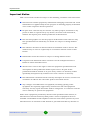
Disposal of Electronic and Electrical Waste
Disposal of Electronic and Electrical Waste
Pursuant to the WEEE EU Directive electronic and electrical waste must not be disposed of with
unsorted waste. Please contact your local recycling authority for disposal of this product.
BreezeMAX PRO 2000 CPE
viii
User Manual
Important Notice
Important Notice
This user manual is delivered subject to the following conditions and restrictions:
This manual contains proprietary information belonging to Alvarion Ltd. Such
information is supplied solely for the purpose of assisting properly authorized
users of the respective Alvarion products.
No part of its contents may be used for any other purpose, disclosed to any
person or firm or reproduced by any means, electronic and mechanical,
without the express prior written permission of Alvarion Ltd.
The text and graphics are for the purpose of illustration and reference only.
The specifications on which they are based are subject to change without
notice.
The software described in this document is furnished under a license. The
software may be used or copied only in accordance with the terms of that
license.
Information in this document is subject to change without notice.
Corporate and individual names and data used in examples herein are
fictitious unless otherwise noted.
Alvarion Ltd. reserves the right to alter the equipment specifications and
descriptions in this publication without prior notice. No part of this
publication shall be deemed to be part of any contract or warranty unless
specifically incorporated by reference into such contract or warranty.
The information contained herein is merely descriptive in nature, and does not
constitute an offer for the sale of the product described herein.
Any changes or modifications of equipment, including opening of the
equipment not expressly approved by Alvarion Ltd. will void equipment
warranty and any repair thereafter shall be charged for. It could also void the
user's authority to operate the equipment.
Some of the equipment provided by Alvarion and specified in this manual, is
manufactured and warranted by third parties. All such equipment must be
installed and handled in full compliance with the instructions provided by such
manufacturers as attached to this manual or provided thereafter by Alvarion or
BreezeMAX PRO 2000 CPE
ix
User Manual
Important Notice
the manufacturers. Non-compliance with such instructions may result in serious
damage and/or bodily harm and/or void the user's authority to operate the
equipment and/or revoke the warranty provided by such manufacturer.
BreezeMAX PRO 2000 CPE
x
User Manual
About This Manual
About This Manual
This manual describes the BreezeMAX PRO 2000 and details how to install,
operate and manage it.
This manual is intended for technicians responsible for installing, setting and
operating the BreezeMAX PRO system, and for system administrators responsible
for managing the system.
This manual contains the following chapters and appendices:
Chapter 1 - Product Description - Describes the BreezeMAX PRO 2000 unit
and its functionality.
Chapter 2 - Hardware Installation - Describes how to install the BreezeMAX
PRO 2000 and how to connect to subscriber’s equipment.
Chapter 3 - Initial Configuration - Describes how to initially configure the
BreezeMAX PRO 2000 in order to test basic link operation.
Chapter 4 - System Settings - Describes general management functions for
the BreezeMAX PRO 2000.
Chapter 5 - Gateway Configuration - Describes the gateway functions of the
BreezeMAX PRO 2000.
Chapter 6 - WiMAX Settings - Describes the WiMAX configuration for the
BreezeMAX PRO 2000.
Chapter 7 - VoIP Settings - Describes the Voice over Internet Protocol
functions of the BreezeMAX PRO 2000.
Chapter 8 - WiFi Settings - Describes the 802.11 b/g radio functions of the
BreezeMAX PRO 2000 3.5 GHz model.
Appendix A - Troubleshooting
Appendix B - GNU License
Glossary - Glossary of terms used in the BreezeMAX PRO 2000 User Manual.
BreezeMAX PRO 2000 CPE
xi
User Manual
Contents
Contents
Chapter 1 - Product Description.............................................................. 1
1.1 Introducing the BreezeMAX PRO 2000 Range.........................................................3
1.1.1 The BreezeMAX PRO 2000 Range of Products .................................................4
1.2 Specifications .............................................................................................................5
1.2.1 WiMAX Radio......................................................................................................5
1.2.2 WiFi Radio...........................................................................................................6
1.2.3 VoIP Specifications ............................................................................................7
1.2.4 Configuration and Management..........................................................................8
1.2.5 Mechanical IDU...................................................................................................8
1.2.6 Mechanical ODU .................................................................................................8
1.2.7 Electrical..............................................................................................................9
1.2.8 Environmental IDU ..............................................................................................9
1.2.9 Environmental ODU ............................................................................................9
1.2.10 Standards Compliance......................................................................................10
Chapter 2 - Hardware Installation......................................................... 11
2.1 Installation Requirements .......................................................................................13
2.1.1 Packing List.......................................................................................................13
2.2 ODU Hardware Description .....................................................................................15
2.2.1 Built-in WiMAX Antenna....................................................................................15
2.2.2 Ethernet RJ-45 Port ..........................................................................................15
2.2.3 SAU Port ...........................................................................................................15
2.2.4 Weatherproof Port Covers ................................................................................16
2.2.5 Ground Screw ...................................................................................................16
2.2.6 Pole-Mounting Bracket Kit.................................................................................17
2.2.7 Tilt-Mount Bracket (Optional) ............................................................................17
2.2.8 SAU (Optional) ..................................................................................................18
2.3 IDU Hardware Description .......................................................................................20
2.3.1 Wi-Fi Antenna (Optional)...................................................................................22
2.3.2 Scan Button.......................................................................................................22
2.3.3 Reset Button .....................................................................................................22
BreezeMAX PRO 2000 CPE
xii
User Manual
Contents
2.3.4 LED Indicators...................................................................................................22
2.3.5 10BASE-T/100BASE-TX LAN Ports .................................................................24
2.3.6 ODU Port...........................................................................................................24
2.3.7 VoIP Phone Ports..............................................................................................25
2.3.8 Power Adapter Socket ......................................................................................25
2.4 Installation Steps......................................................................................................26
2.5 ODU Installation .......................................................................................................27
2.5.1 ODU Location....................................................................................................27
2.5.2 Mount the Unit...................................................................................................27
2.6 IDU Installation .........................................................................................................30
2.6.1 Select a location................................................................................................30
2.6.2 Installing the unit ...............................................................................................30
2.7 ODU Cable Connections..........................................................................................32
2.7.1 ODU-IDU Ethernet Cable Connection...............................................................32
2.7.2 10/100BASE-TX Pin Assignments ....................................................................36
2.7.3 BreezeMAX PRO 2000 Cables .........................................................................38
2.8 ODU Antenna Alignment .........................................................................................39
2.8.1 Align the WiMAX Antenna.................................................................................40
Chapter 3 - Initial Configuration............................................................ 42
3.1 Introduction ..............................................................................................................44
3.1.1 Accessing the Web Management Interface ......................................................44
3.1.2 Using the Basic Setup.......................................................................................45
3.2 The Advanced Setup Menu .....................................................................................48
BreezeMAX PRO 2000 CPE
xiii
User Manual
Contents
Chapter 4 - System Settings ................................................................. 50
4.1 Introduction ..............................................................................................................52
4.2 Host Name.................................................................................................................53
4.3 System Status...........................................................................................................54
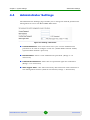
4.4 Administrator Settings.............................................................................................56
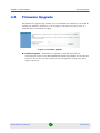
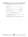
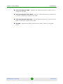
4.5 Firmware Upgrade....................................................................................................57
4.6 Configuration Tools .................................................................................................58
4.7 System Time .............................................................................................................60
4.8 TR069 Settings .........................................................................................................62
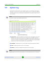
4.9 System Log ...............................................................................................................64
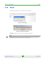
4.10 Reset .........................................................................................................................65
Chapter 5 - Gateway Configuration....................................................... 66
5.1 Introduction ..............................................................................................................68
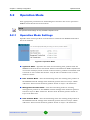
5.2 Operation Mode ........................................................................................................69
5.2.1 Operation Mode Settings ..................................................................................69
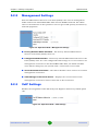
5.2.2 Management Settings .......................................................................................70
5.2.3 VoIP Settings ....................................................................................................70
5.3 WAN Settings............................................................................................................71
5.3.1 Dynamic IP Address..........................................................................................72
5.3.2 Static IP Settings...............................................................................................72
5.3.3 L2TP Settings....................................................................................................73
5.3.4 PPPoE Settings.................................................................................................74
5.4 LAN ............................................................................................................................75
5.4.1 LAN Settings .....................................................................................................75
5.4.2 DHCP Client List ...............................................................................................77
5.5 NAT ............................................................................................................................78
5.5.1 Virtual Server ....................................................................................................78
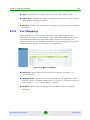
5.5.2 Port Mapping.....................................................................................................79
5.5.3 DMZ ..................................................................................................................80
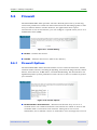
5.6 Firewall ......................................................................................................................81
BreezeMAX PRO 2000 CPE
xiv
User Manual
Contents
5.6.1 Firewall Options ................................................................................................81
5.6.2 Client Filtering ...................................................................................................82
5.6.3 MAC Control......................................................................................................83
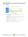
5.7 Route .........................................................................................................................84
5.8 UPnP..........................................................................................................................85
Chapter 6 - WiMAX Settings .................................................................. 86
6.1 Introduction ..............................................................................................................88
6.2 WiMAX Login ............................................................................................................89
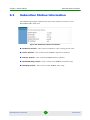
6.3 Subscriber Station Information...............................................................................92
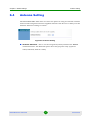
6.4 Antenna Setting........................................................................................................93
6.5 Advanced Configuration..........................................................................................94
Chapter 7 - VoIP Settings ...................................................................... 96
7.1 Introduction ..............................................................................................................98
7.2 SIP Account ..............................................................................................................99
7.3 SIP Setting ..............................................................................................................101
7.4 Dial Plan ..................................................................................................................103
7.5 Call Feature.............................................................................................................105
7.6 Codecs ....................................................................................................................107
7.7 Call Block Setting...................................................................................................109
7.8 Phone Setting .........................................................................................................110
Chapter 8 - WiFi Settings..................................................................... 112
8.1 Introduction ............................................................................................................114
8.2 Wireless Settings ...................................................................................................115
8.3 Wireless Security ...................................................................................................119
8.3.1 Wireless Security ............................................................................................119
8.3.2 WEP Shared Key Security ..............................................................................120
8.3.3 WPA/WPA2 Security.......................................................................................121
8.4 MAC Authentication ...............................................................................................122
BreezeMAX PRO 2000 CPE
xv
User Manual
Contents
Appendix A - Troubleshooting ............................................................ 124
Appendix B - GNU License ................................................................. 128
B.1 The GNU General Public License .........................................................................130
B.1.1 Preamble.........................................................................................................131
B.1.2 GNU GENERAL PUBLIC LICENSE TERMS AND CONDITIONS FOR COPYING,
DISTRIBUTION AND MODIFICATION132
BreezeMAX PRO 2000 CPE
xvi
User Manual
Chapter
1
Product Description
Chapter 1 - Product Description
In This Chapter:
“Introducing the BreezeMAX PRO 2000 Range” on page 3
“The BreezeMAX PRO 2000 Range of Products” on page 4
“Specifications” on page 5
BreezeMAX PRO 2000 CPE
2
User Manual
Chapter 1 - Product Description
1.1
Introducing the BreezeMAX PRO 2000 Range
Introducing the BreezeMAX PRO 2000
Range
BreezeMAX PRO 2000 is a combined set of indoor (IDU), and outdoor (ODU) units
that are either 2.3 GHz, 2.5GHz, or 3.5 GHz, high capacity residential gateways
and WiMAX™ Wireless Broadband Access subscriber stations, for a home or small
office. Which ODU set you use depends on the frequency band of your service
provider’s WiMAX service. Each system provides network connections that are
always on, supporting immediate access to the Internet and other IP services at
high data rates. The unit provides a gateway function between a WiMAX service
provider and a local Ethernet LAN. The device enables a service provider to deliver
last mile broadband wireless access as an alternative to wired DSL or cable
modems.
Part of an extended and field-proven product portfolio, BreezeMAX PRO 2000 is
an integral part of the BreezeMAX family, the latest most technologically advanced
wireless solution for broadband deployment. With capacity of up to 13 Mbps
download and 3.5 Mbps upload speed per unit, the BreezeMAX PRO 2000 solution
enables the delivery of powerful wireless broadband services to the subscriber.
BreezeMAX PRO 2000 is an out-of-the-box solution with immediate available local
stock enabling virtually instant network expansion and simplified deployment.
BreezeMAX PRO 2000 provides a wireless solution for the subscriber to connect to
the internet.
With a range of up to 15 Km and lower equipment and deployment costs,
BreezeMAX PRO 2000 enables service providers to wirelessly extend their services
to customers in areas where the cost of cabling is prohibitive to deployment.
Remote residential areas can now benefit from high-speed wireless Internet
access, Web browsing and e-mail, and advanced applications such as multi-media
services. The BreezeMAX PRO 2000 indoor unit (IDU) is a plug-and-play device.
The BreezeMAX PRO 2000 includes one or four RJ-45 Ethernet switch ports for
LAN connections and two RJ-11 Voice over IP (VoIP) phone ports. An 802.11b/g
Wi-Fi module is included that provides a local Wi-Fi access point service. The IDU
also includes a dedicated Power-over-Ethernet (PoE) RJ-45 port that connects to
the ODU.
BreezeMAX PRO 2000 CPE
3
User Manual
Chapter 1 - Product Description
1.1.1
Introducing the BreezeMAX PRO 2000 Range
The BreezeMAX PRO 2000 Range of Products
The following tables list the available BreezeMAX PRO 2000 models. Each ODU
can be associated with all IDUs.
Table 1-1: Outdoor Units
Frequency Band
Model Number
Description
2.3
4M-CPE-ODU-PRO-2.3
Outdoor 2.3GHz band WiMAX unit
with integrated antenna
2.5
4M-CPE-ODU-PRO-2.5
Outdoor 2.5GHz band WiMAX unit
with integrated antenna
3.5
4M-CPE-ODU-PRO-3.5
Outdoor 3.5GHz band WiMAX unit
with integrated antenna
Table 1-2: Indoor Units
Model Number
Description
4M-CPE-IDU-PRO-1D
One data port Indoor gateway unit
4M-CPE-IDU-PRO-1D2V
One data port and two voice Indoor gateway unit
4M-CPE-IDU-PRO-4D2V-WiFi
Four data port, two voice and WiFi Indoor gateway unit
The BreezeMAX PRO 2000 offers a user-friendly web-based management interface
for the configuration of all the unit’s features. Any PC directly attached to the unit
can access the management interface using a web browser, such as Internet
Explorer (version 6.0 or above) or Firefox (version 1.5 or above).
The initial configuration steps can be made through the web browser interface
using the Setup Wizard. It is recommended to make the initial changes by
connecting a PC directly to one of the BreezeMAX PRO 2000’s LAN ports.
BreezeMAX PRO 2000 CPE
4
User Manual
Chapter 1 - Product Description
Specifications
1.2
Specifications
1.2.1
WiMAX Radio
Table 1-3: WiMAX Radio Specifications
Item
Description
Radio Type
IEEE 802.16e WAVE 1 & WAVE 2
Frequency Band
2300 MHz, or
2500 MHz, or
3500 MHz
Antenna Type (ODU)
Integrated Flat Panel Antenna, 17dBi, 24°AZ x 18°EL.
Channel Bandwidth
5.00, 7.00, 8.75, and 10.00 MHz
Maximum Throughput
3.5 Mbps Upload, 13 Mbps download
Antenna Technology
Maximum-Ratio Combining (MRC)
Modulation Technique
Scaleable OFDMA employing Time-Division Duplex (TDD)
mechanism
PRBS subcarrier randomization
Contains pilot, preamble, and ranging modulation
FEC Coding Rates
Down Link: QPSK, 16 QAM, 64 QAM
Up Link: QPSK, 16 QAM, 64 QAM
Max Tx Power Levels at Antenna
Port
Flat panel antenna:
2.3 GHz: 12 dBi
2.5 GHz: 12 dBi
3.5 GHz: 15 dBi
TPL (Transmit Power Level)
+24 dBm maximum
Receive Sensitivity
-94 dBm maximum
BreezeMAX PRO 2000 CPE
5
User Manual
Chapter 1 - Product Description
1.2.2
Specifications
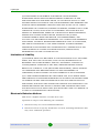
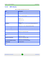
WiFi Radio
Table 1-4: WiFi Radio Specifications IDU
Item
Description
Radio Type
IEEE 802.16b, IEE 802.11g
Frequency Band
2.4 ~ 2.4835 GHz (US, Canada, ETSI)
2.4 ~ 2.497 GHz (Japan)
Maximum Channels
FCC/IC: 1-11
ETSI: 1-13
France: 10-13
MKK: 1-14
Data Rates
802.11g: 6, 9, 11, 12, 18, 24, 36, 48, 54 Mbps (automatic fall
back)
802.11b: 1, 2, 5.5, 11 Mbps (automatic fall back)
Maximum Throughput
2 Mbps Upload, 5 Mbps download
Radio Technology
Orthogonal Frequency Divisional Multiplexing (OFDM)
Modulation Technique
802.11g: CCK, BPSK, QPSK, OFDM
802.11b: CCK, BPSK, QPSK
FEC Coding Rates
1/2 2/3, 3/4
Max Tx Power Levels at Antenna
Port
802.11b: 18 dBm*
802.11g: 14 dBm*
RF Receive Sensitivity
802.11b: -88 dBm @ 11 Mbps
802.11g: -74 dBm @ 54 Mbps
TPC (Transmit Power Control)
100%, 50%, 25%, 12.5%, Min (0 dBm).
Antenna Type
Diversity Antenna
*The maximum value can be lower depending on the radio band and modulation used. Check Table 1-7 for
details
BreezeMAX PRO 2000 CPE
6
User Manual
Chapter 1 - Product Description
1.2.3
Specifications
VoIP Specifications
Table 1-5: VoIP Specifications
Item
Description
Voice Signalling Protocol
SIP v2 (RFC 3261)
Voice Codex
G.711 (a-law and u-law)
G.726
G.729ab
G.723
Voice Quality
VAD (Voice Activity Detection)
CNG (Comfortable Noise Generation)
Echo cancellation (G.165/G.168)
Adaptive jitter buffer, up to 200 milliseconds
DTMF tone detection and generation
Call Features
Call transfer
Call waiting/hold/retrieve
3-way conference call
Call blocking
T.38 fax relay
Dial plan (E.164 dialing plan)
Call forwarding: No Answer/Busy/All
REN (Ring Equivilent Number)
BreezeMAX PRO 2000 CPE
3 REN total in system
7
User Manual
Chapter 1 - Product Description
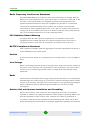
1.2.4
Specifications
Configuration and Management
Table 1-6: Configuration and Management
Item
Description
Management options
Web-based (HTTP/HTTPS)
TR-069
Management access
From Wired LAN, Wireless Link
Management access protection
Access Password
Encryption
WEP 152-bits
Allocation of IP parameters
Configurable or automatic (DHCP client)
Software upgrade
HTTP
Configuration Upload/Download
HTTP
1.2.5
Mechanical IDU
Table 1-7: Mechanical Specifications
Item
Description
Dimensions
169mm (H) X 184mm (W) X 80 (T) X 74mm
Weight
1.6kg
Mounting
Desktop
Cabling
Category 5 cable connection
1.2.6
Mechanical ODU
Table 1-8: Mechanical Specifications
Item
Description
Dimensions
230mm (H) X 230mm (W) X 63 (T) mm
Weight
2kg
Mounting
Pole-mount
Cabling
Category 5 cable connection
BreezeMAX PRO 2000 CPE
8
User Manual
Chapter 1 - Product Description
1.2.7
Specifications
Electrical
Table 1-9: Electrical Specifications
Type
Details
AC Power Supply
Input: 100-240 VAC, 50-60 Hz, maximum power consumption 0.5A
Output: 19 VDC, maximum power consumption 3.4A
BreezeMAX Power Supply
DC Input: 9~19 VDC, 2 A maximum
Power Consumption: 11 W maximum
1.2.8
Environmental IDU
Table 1-10: Environmental Specifications
Item
Details
Operating Temperature
-5ºC to 45ºC
Storage Temperature
-40 to 75 °C
Humidity
Maximum 95%, non-condensing.
1.2.9
Environmental ODU
Table 1-11: Environmental Specifications
Item
Details
Operating Temperature
-40ºC to 55ºC
Storage Temperature
-40 to 70 °C
Humidity
Maximum 95%, non-condensing.
BreezeMAX PRO 2000 CPE
9
User Manual
Chapter 1 - Product Description
Specifications
1.2.10 Standards Compliance
Table 1-12: Standards Compliance
Type
Standard
EMC
FCC Part 15B Class B
ETSI EN 301 498-1/4
EN 55022 Class B
Safety
UL 60950-1
EN 60950-1 / IEC 60950-1
Radio
FCC Part 27
ETSI EN 302 544-2
EN 302 326-1, EN 302 326-2
WiFi Radio
FCC Part 15 Subpart C
EN 300 328
Standards
IEEE 802.16e-2005 WAVE 1 and WAVE 2
IEEE 802.3-2005 10BASE-T and 100BASE-TX
IEEE 802.11b and 802.11g
UPnP
BreezeMAX PRO 2000 CPE
10
User Manual
Chapter
2
Hardware Installation
Chapter 2 - Hardware Installation
In This Chapter:
“Installation Requirements” on page 13
“Packing List” on page 13
“ODU Hardware Description” on page 15
“Installation Steps” on page 26
“ODU Installation” on page 27
“IDU Installation” on page 30
“ODU Cable Connections” on page 32
“ODU Antenna Alignment” on page 39
“Align the WiMAX Antenna” on page 40
BreezeMAX PRO 2000 CPE
12
User Manual
Chapter 2 - Hardware Installation
2.1
Installation Requirements
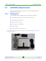
Installation Requirements
This section describes how to install and connect the BreezeMAX PRO 2000
WiMAX Residential Gateway.
2.1.1
Packing List
The BreezeMAX PRO 2000 package includes the following components:
BreezeMAX PRO 2000 ODU unit with integrated antennas*
BreezeMAX PRO 2000 IDU unit
ODU pole mount bracket kit
RJ-45 Category 5 network cable
AC power adapter
Software Utilities and User Guide CD
*For the bandwidth specification of your choice of model see “The BreezeMAX PRO 2000 Range of
Products” on page 4
BreezeMAX PRO 2000 CPE
13
User Manual
Chapter 2 - Hardware Installation
Installation Requirements
Optional:
Wi-Fi antenna (is included with BreezeMAX PRO 2000 CPE Wi-Fi model)
Tilt mount bracket.
SAU
BreezeMAX PRO 2000 CPE
14
User Manual
Chapter 2 - Hardware Installation
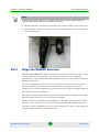
2.2
ODU Hardware Description
ODU Hardware Description
Built-in Antenna
SAU Port
Ground
Screw
Ethernet RJ-45 Port
2.2.1
Built-in WiMAX Antenna
One high-gain internal antenna is built into the ODU for WiMAX communications.
The antenna must be aligned towards the direction of the WiMAX service
provider’s base station.
2.2.2
Ethernet RJ-45 Port
The ODU has one standard RJ-45 PoE port that connects to the IDU using
Ethernet cable. The Ethernet port connection provides power to the ODU as well
as a data link to the IDU.
2.2.3
SAU Port
A Subscriber Unit Alignment Unit (SAU) port is included for connecting an
optional SAU device that provides indicator status LEDs for antenna alignment.
BreezeMAX PRO 2000 CPE
15
User Manual
Chapter 2 - Hardware Installation
ODU Hardware Description
SAU Port
Ethernet RJ-45 Port
2.2.4
Weatherproof Port Covers
The ODU includes rubber weatherproof port covers for the RJ-45 and SAU ports.
The RJ-45 port cover allows the Ethernet cable to be fed through and connected to
the RJ-45 port. The SAU port cover protects the SAU port when it is not in use.
2.2.5
Ground Screw
The ODU includes its own built-in lightning protection, it is important that the
unit is properly connected to ground. A grounding screw is provided for attaching
a ground wire to the unit.
To ground the unit please follow the guidelines below:
Be sure to use #14 AWG category cable to ground the unit.
The unit can be grounded to the bracket or to the pole, alternatively you can
ground the unit straight to earth.
If grounding to the bracket or the pole make sure that you attach the
grounding wire to a non-painted exposed part of either. Subsequently make
sure that the pole is grounded to earth.
BreezeMAX PRO 2000 CPE
16
User Manual
Chapter 2 - Hardware Installation
ODU Hardware Description
Grounding Point
2.2.6
Pole-Mounting Bracket Kit
The ODU includes a bracket kit that is used to mount the unit to a pole, radio
mast, or part of a tower structure.
Pole Mount
Bracket
2.2.7
Tilt-Mount Bracket (Optional)
The ODU may be mounted to a pole with an optional tilt-mount bracket which
provides greater scope and accuracy for adjusting the antenna direction of the
ODU to the transmitting Access Unit (base-station).
BreezeMAX PRO 2000 CPE
17
User Manual
Chapter 2 - Hardware Installation
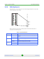
2.2.8
ODU Hardware Description
SAU (Optional)
The SAU device can be connected to the ODU during installation to assist with
antenna alignment and testing.
WLNK
ET PW AL
When connected to the ODU, the SAU provides status LED indications as
described in the following table:
:
Table 2-1: SAU LED Indicators
LED
Status
Description
AL (Alarm)
Off
The diagnostic test has passed and the ODU is operating
normally.
On Red
An ODU failure has been detected.
Off
The ODU is not receiving power or there is an internal 3.3 VDC
failure.
On Green
The SAU is receiving power from the ODU.
Off
There is no valid Ethernet link between the ODU and the IDU.
On Green
There is a valid Ethernet link between the ODU and the IDU.
PW (Power)
ET
(Ethernet)
BreezeMAX PRO 2000 CPE
18
User Manual
Chapter 2 - Hardware Installation
ODU Hardware Description
Table 2-1: SAU LED Indicators
LED
Status
Description
WLNK
(Wireless
link)
Off
The ODU is not connected to a base station.
On Orange
The ODU is connected to and receives services from a base
station (Network Entry completed). Link quality is indicated by
LEDs 1-9, as described below.
Blinking Orange
Authentication has failed due to one of the following reasons
(indicated by the WiMAX Link LEDs):
If LEDs 6, 7 and 8 are on: Authentication has been rejected by
the RADIUS server.
If LEDS 7 and 8 are on: Authentication has been rejected by
the base station (due to a duplicate subscriber unit name in its
database).
If LED 8 is on: Authentication has failed due to a timeout, or
there was a re-authentication failure (connection to the
RADIUS server was lost or a mismatched shared secret).
1
On Green
5dB SNR < 10dB
1-2
On Green
10dB SNR < 15dB
1-3
On Green
15dB SNR < 20dB
1-4
On Green
20dB SNR < 24dB
1-5
On Green
SNR 24dB and RSSI < -75dBm
1-6
On Green
SNR 24dB and RSSI -75dBm
1-7
On Green
SNR 24dB and RSSI -70dBm
1-8
On Green
SNR 24dB and RSSI -60dBm
1-9
1-8 On Green
9 On Red
RSSI -20dBm (saturation)
1-8 in
sequence
Cycle On/Off
Green
Indicates a full frequency scan in progress.
5, 4&6, 3&7,
2&8, 1 in
sequence
Cycle On/Off
Green
Selecting a detected base station with the strongest signal, or a
short scan.
BreezeMAX PRO 2000 CPE
19
User Manual
Chapter 2 - Hardware Installation
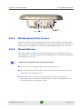
2.3
IDU Hardware Description
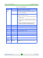
IDU Hardware Description
The front of the IDU provides an array of system status indicators. The back
includes four LAN ports for 10/100 Mbps Ethernet connections, two RJ-11 Voice
over IP (VoIP) phone ports, and the DC power jack. One additional RJ-45 port is
for connection to the ODU, providing both a data link and power to the ODU unit.
The following figures show the external components of the IDU:
2.4 GHz Wi-Fi Antennas
Scan Button
Power Status
Indicator
Wi-Fi Indicator
BreezeMAX PRO 2000 CPE
20
User Manual
Chapter 2 - Hardware Installation
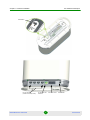
IDU Hardware Description
Reset Button
RJ-45 LAN Ports
(include Link/Activity LEDs)
BreezeMAX PRO 2000 CPE
RJ-45 Power and
Data Port
21
VoIP Phone Ports
Power Socket
User Manual
Chapter 2 - Hardware Installation
IDU Hardware Description
CAUTION
Due to the DC current the unit draws from its power socket, DO NOT connect a PC to the RJ-45
Data and Power port.
2.3.1
Wi-Fi Antenna (Optional)
The IDU includes 802.11b/g Wi-Fi. There is a single 2.4 GHz antenna included for
local wireless connections to PCs.
2.3.2
Scan Button
This button performs no function on the BreezeMAX PRO 2000 IDU unit.
2.3.3
Reset Button
This button is used to reset the IDU or restore the factory default configuration. If
you press the button for less than 1 second, the unit will perform a hardware
reset. If you press and hold down the button for 5 seconds or more, any
configuration changes you may have made are removed, and the factory default
configuration is restored to the unit.
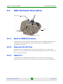
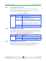
2.3.4
LED Indicators
The figure below shows the BreezeMAX Si 2000’s LED status indicators. Each
LED is described in the sections that follow.
Power LED
WiFi LED
WiMAX Signal
Strength LEDs
Figure 2-1: LEDs
BreezeMAX PRO 2000 CPE
22
User Manual
Chapter 2 - Hardware Installation
2.3.4.1
IDU Hardware Description
Power Status Indicator LED
The BreezeMAX Si 2000 includes a Power LED indicator that simplifies
installation and WiMAX network troubleshooting. The LED, which is located on
the front panel, is described in the following table.
Table 2-2: Power Status LEDs
LED
Status
Description
Power
On Green
Power is supplied to the unit.
Flashing Green
When flashing with three of the WiMAX signal LEDs turned
on, indicates authentication has failed.
On Orange
Indicates one of the following conditions:
After power on, indicates the unit is running its self test.
Indicates the network entry process has restarted.
2.3.4.2
On Red
A system failure has occured.
Off
No power is being supplied to the unit.
Wi-Fi Status Indicator LED
The 3.5 GHz BreezeMAX Si 2000 model, which supports Wi-Fi operation, includes
a Wi-Fi LED indicator that displays the Wi-FI network status. The LED, which is
located on the front panel, is described in the following table:
Table 2-3: Wi-Fi Status Indicator LED
2.3.4.3
LED
Status
Description
WiFi
On Green
The Wi-Fi radio is enabled and operating normally.
Flashing Green
Indicates data traffic in the Wi-Fi network.
Off
There is no Wi-Fi connection or the radio is disabled.
WiMAX Signal Indicator LEDs
The BreezeMAX Si 2000 includes seven WiMAX signal strength LED indicators
that display the current WiMAX receive signal status. The LEDs, which are
located on the front panel, are described in the following table.
BreezeMAX PRO 2000 CPE
23
User Manual
Chapter 2 - Hardware Installation
IDU Hardware Description
Table 2-4: WiMAX Signal Indicator LEDs
2.3.5
LED
Status
Description
1
On Green
Indicates the receive signal is between 5 dB and 8 dB.
2
On Green
Indicates the receive signal is between 8 dB and 12 dB.
3
On Green
Indicates the receive signal is between 12 dB and 15 dB.
4
On Green
Indicates the receive signal is between 15 dB and 18dB.
5
On Green
Indicates the receive signal is between 18 dB and 20 dB.
6
On Green
Indicates the receive signal is between 20 dB and 25 dB.
7
On Green
Indicates the receive signal is 25 dB or more.
All 7 LEDs
Off
No power is being supplied to the unit.
10BASE-T/100BASE-TX LAN Ports
The IDU provides four 10BASE-T/100BASE-TX RJ-45 ports. These LAN ports are
standard RJ-45 Ethernet network ports that connect directly to PCs. They can
also be connected to an Ethernet switch or hub to support more users.
All ports support automatic MDI/MDI-X operation, so you can use
straight-through cables for all network connections to PCs or servers, or to other
switches or hubs. Each of these ports support auto-negotiation, so the optimum
transmission mode (half or full duplex), and data rate (10 or 100 Mbps) is selected
automatically.
Each RJ-45 port includes a built-in LED indicator. This LED indicator is
described in the following table.
Table 2-5: LAN Port Status LED Indicators
Status
Description
Link/Activity
2.3.6
On Green
Ethernet port has a valid link with an attached device.
Flashing Green
The port is transmitting or receiving data.
Off
Ethernet port has no link with another device.
ODU Port
The IDU includes one RJ-45 port that supports a Power-over-Ethernet (PoE)
connection to the ODU.
BreezeMAX PRO 2000 CPE
24
User Manual
Chapter 2 - Hardware Installation
IDU Hardware Description
CAUTION
Due to the DC current the unit draws from its power socket, DO NOT connect a PC to the RJ-45
Data and Power port.
2.3.7
VoIP Phone Ports
The IDU provides two RJ-11 telephone ports that connect directly to a standard
(analog) telephone set. This allows a regular telephone to be used for making VoIP
calls over the Internet.
2.3.8
Power Adapter Socket
The power socket is located on the rear panel of the IDU. The power socket is for
the AC power adapter connection.
The unit is powered on when connected to its AC power adapter, and the power
adapter is connected to an AC power source between 100-240 volts at 50-60Hz.
CAUTION
Use ONLY the power adapter supplied with the BreezeMAX PRO 2000. Otherwise, the product may
be damaged.
BreezeMAX PRO 2000 CPE
25
User Manual
Chapter 2 - Hardware Installation
2.4
Installation Steps
Installation Steps
CAUTION
Only the BreezeMAX PRO 2000 ODU can be installed outdoors.
The BreezeMAX PRO 2000 IDU is an indoor unit and must not be installed outdoors.
ONLY experienced installation professionals who are familiar with local building and safety codes
and, wherever applicable, are licensed by the appropriate government regulatory authorities should
install outdoor antennas.
Failure to abide may void the BreezeMAX PRO 2000 product warranty and may expose the end
user or Service Provider to legal and financial liabilities. Alvarion and its resellers or distributors are
not liable for injury, damage or regulation violations associated with the installation of Outdoor
antennas.
Before installing the BreezeMAX, verify that you have all the items listed in the
package checklist above. If any of the items are missing or damaged, contact your
local dealer. Also, be sure you have all the necessary tools and cabling before
installing the BreezeMAX PRO.
Hardware installation of the OD200 involves these steps:
Mount the ODU on a pole, mast, or tower using the mounting bracket.
Install the IDU indoors.
Connect the ODU-IDU Ethernet cable and a grounding wire to the ODU.
Align the ODU antenna with the base station.
BreezeMAX PRO 2000 CPE
26
User Manual
Chapter 2 - Hardware Installation
2.5
ODU Installation
ODU Installation
The ODU includes its own bracket kit for mounting the unit to a 1 to 4 inch
diameter steel pole or tube. The pole-mounting bracket allows the unit to be
mounted to part of a radio mast or tower structure.
CAUTION
The planning and installation of the ODU requires professional personnel that are trained in the
installation of radio transmitting equipment. The user is responsible for compliance with local
regulations concerning items such as building safety codes, use of lightning arrestors, and
grounding. Therefore, you must consult a professional contractor knowledgeable in local radio
regulations prior to equipment installation.
2.5.1
ODU Location
The ODU should be installed outdoors, mounted to a pole using the included
mounting bracket.
When selecting an suitable location for the unit, consider these points:
The ODU should be installed where it can provide a direct, or near line of sight
with the WiMAX base station. Normally, the higher the unit placement, the
better the link quality.
Make sure there are no other radio antennas within 2 m (6 ft) of the ODU.
Place the ODU away from power and telephone lines.
Avoid placing the ODU too close to any metallic, reflective surfaces, such as
roof-installed air-conditioning equipment, wire fences, or water pipes.
2.5.2
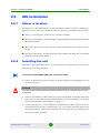
Mount the Unit
The ODU’s pole-mounting bracket attaches directly to the ODU using two long
threaded bolts. The bracket has V-shaped edges on one side that clamp the unit
to a pole. The bracket allows the ODU’s built-in antenna to be mounted to a pole
in either a vertical or horizontal polarization direction.
Perform the following steps to mount the unit to a 1 to 4 inch diameter steel pole or
tube using the mounting bracket:
BreezeMAX PRO 2000 CPE
27
User Manual
Chapter 2 - Hardware Installation
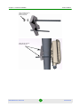
1
ODU Installation
Attach the two threaded bolts to the back of the ODU using a flat screwdriver.
Make sure you use the correct threaded holes for the required polarization.
NOTE
Antennas in a wireless link must be mounted in the same polarization direction.
Directional Arrow
Attach the two
threaded bolts to the
ODU using a flat
screwdriver
Vertical Positioning
Directional Arrow
Horizontal Positioning
2
Place the ODU against one side of the pole and then fit the bracket onto the
threaded bolts. The bracket’s V-shaped edges should be against the pole.
NOTE
Make sure that the ODU connectors always face downward.
3
Use the included nuts and washers to secure the ODU to the pole. The
securing nuts should be just tight enough to hold the ODU to the pole. (The
bracket may need to be rotated around the pole during the antenna alignment
process.)
BreezeMAX PRO 2000 CPE
28
User Manual
Chapter 2 - Hardware Installation
ODU Installation
Use the provided nuts and
washers to attach the
bracket to the bolts
Tighten the nuts to secure
the ODU to the pole
BreezeMAX PRO 2000 CPE
29
User Manual
Chapter 2 - Hardware Installation
2.6
IDU Installation
2.6.1
Select a location
IDU Installation
The IDU can be installed indoors on any horizontal surface, such as a desktop or
shelf. Be sure to select an suitable location for the device. Consider these points:
Select a cool, dry place, which is out of direct sunlight.
The device should have adequate space (approximately two inches) on all sides
for proper air flow.
The device must be near an AC power outlet that provides 100 to 240 V, 50 to
60 Hz.
The device should be accessible for network cabling and allow the status LED
indicators to be clearly visible.
2.6.2
Installing the unit
The IDU is a plug-and-play device, so once it has been connected to your PC and
powered up, it is fully operable.
To connect the BreezeMAX PRO 2000, follow these steps:
1
Power on the IDU by connecting the AC power adapter and plugging it into an
AC power source.
CAUTION
Use ONLY the power adapter supplied with the BreezeMAX PRO 2000. Otherwise, the product may
be damaged.
2
Observe the Indicator LEDs. When you power on the IDU, verify that the Power
LED turns on and that the other LED indicators start functioning as described
under “IDU Hardware Description” on page 1-5.
3
Connect Category 5 or better Ethernet cables from the IDU’s LAN ports to the
network ports of your PCs. Alternatively, you can connect the LAN ports to an
Ethernet switch or other devices. Make sure the length of each cable does not
exceed 100 meters (328 ft).
BreezeMAX PRO 2000 CPE
30
User Manual
Chapter 2 - Hardware Installation
IDU Installation
If your PCs are powered on, the RJ-45 LAN port LEDs on the IDU should turn
on to indicate valid links.
4
Connect one or two standard (analog) telephone sets to the IDU’s VoIP ports
using standard telephone cable with RJ-11 plugs.
The IDU enables VoIP calls to be made through the unit using a standard
(analog) telephone set connected to a VoIP port, or from PCs or other network
devices connected to the LAN ports. Standard Session Initiation Protocol (SIP)
technology is used to make VoIP calls. You must access the web interface and
configure settings for your SIP service provider before being able to make VoIP
calls.
5
Use your PC’s web browser to access the unit’s management interface and run
the Setup Wizard to make any configuration changes. For more information,
see Chapter 3, “Initial Configuration.”
BreezeMAX PRO 2000 CPE
31
User Manual
Chapter 2 - Hardware Installation
2.7
ODU Cable Connections
ODU Cable Connections
The ODU needs to be connected to the IDU using Ethernet cable, and the ODU
must be grounded by connecting a grounding wire.
2.7.1
ODU-IDU Ethernet Cable Connection
Use outdoor-rated Category 5E or better Ethernet cable with RJ-45 connectors on
each end. Before connecting the cable, first plan a cable route from the ODU
outdoors to the IDU indoors. Consider these points:
Make sure the cable length does not exceed 90 meters (295 ft).
Determine a building entry point for the cable.
Determine if conduits, bracing, or other structures are required for safety or
protection of the cable.
Be sure to ground the outdoor-rated Ethernet cable immediately before it
enters the building.
For additional lightning protection, it is recommended to use a lightning
arrestor immediately before the Ethernet cable enters the building.
To connect the ODU-IDU Ethernet cable, follow these steps:
1
Remove the rubber sealing cover from the IDU COM port on the ODU.
2
Cut the Ethernet cable to the required length and feed it through the port
cover. Then use a crimp tool to attach an RJ-45 connector to the Ethernet
cable.
Make sure the Ethernet twisted-pair wires are attached to the RJ-45 connector
following standard pin assignments.
3
Connect the Ethernet cable to the IDU COM RJ-45 connector.
4
Screw the port cover back into the unit and tighten it to ensure protection
against moisture.
5
Seal the IDU COM connector using tar seal or weatherproof tape to protect
against rain and moisture.
BreezeMAX PRO 2000 CPE
32
User Manual
Chapter 2 - Hardware Installation
6
ODU Cable Connections
Route the Ethernet cable from the ODU to the IDU following your cable plan
and connect it to the ODU port on the IDU. The RJ-45 port LED on the IDU
should turn on to indicate a valid link.
NOTE
Connecting the Ethernet cable to the IDU powers on the ODU.
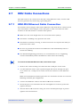
The sequence of inserting the RJ-45 cable into the ODU and the supplied ODU
components are described in the following diagram.
RJ-45 cable
Rubber sealing
cap
Plastic crimp
Internal sealing
chamber
Screw-off
external chamber
RJ-45 port
7
Insert the sealing cover into the port to ensure protection against moisture.
BreezeMAX PRO 2000 CPE
33
User Manual
Chapter 2 - Hardware Installation
8
ODU Cable Connections
Seal the IDU COM connector using tar seal or weatherproof tape to protect
against rain and moisture.
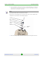
2.7.1.1
Ground Wire Connection
When connecting a ground wire to the ODU, use the grounding screw located on
the base of the unit. Be sure to use #14 AWG or larger copper core ground wire.
CAUTION
Be sure that grounding is available and that it meets local and national electrical codes. Grounding
the ODU must be performed by a professional installer.
To connect a grounding wire to the ODU, follow these steps:
1
Crimp a ring lug onto the end of the ground wire before connecting it to the
unit.
2
Place the ground wire lug on the grounding point and firmly tighten the screw.
BreezeMAX PRO 2000 CPE
34
User Manual
Chapter 2 - Hardware Installation
ODU Cable Connections
Ground Screw Chamber
3
Connect the other end of the grounding wire to a good ground (earth)
connection.
NOTE
Use cable strips to secure all cables to the pole.
Grounding
Screw
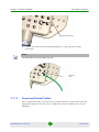
2.7.1.2
Preparing Ethernet Cables
Use a crimp tool for RJ-45 connectors to prepare the wires. Insert them into the
appropriate pins and use the tool to crimp the connector. Make sure to do the
following:
BreezeMAX PRO 2000 CPE
35
User Manual
Chapter 2 - Hardware Installation
ODU Cable Connections
Remove as small a length as possible of the external jacket. Verify that the
external jacket is well inside the sealing cover when connected to the unit, to
ensure good sealing.
Pull back the shield drain wire before inserting the cable into the RJ-45
connector, to ensure a good connection with the connector's shield after
crimping.
For 10/100BASE-TX connections, a twisted-pair cable must have two pairs of
wires. Each wire pair is identified by two different colors. For example, one
wire might be green and the other, green with white stripes. Also, an RJ-45
connector must be attached to both ends of the cable.
CAUTION
Each wire pair must be attached to the RJ-45 connectors in a specific orientation.
DO NOT plug a phone jack connector into the RJ-45 port. Use only twisted-pair cables with RJ-45
connectors that conform with FCC standards.
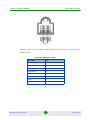
The following figure illustrates how the pins on the RJ-45 connector are
numbered. Be sure to hold the connectors in the same orientation when attaching
the wires to the pins.
1
2.7.2
8
8
1
10/100BASE-TX Pin Assignments
The BreezeMAX PRO cable provides pin-to-pin connection on both ends.
The following figure shows the required wire pair connections.
BreezeMAX PRO 2000 CPE
36
User Manual
Chapter 2 - Hardware Installation
ODU Cable Connections
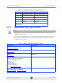
The color codes used in standard cables supplied by Alvarion are as listed in the
following table:
Table 2-6: Cable Color Codes
BreezeMAX PRO 2000 CPE
Wire color
Pin
Blue
1
Blue/white
2
Orange
3
Orange/white
6
Brown
4
Brown/white
5
Green
7
Green/white
8
37
User Manual
Chapter 2 - Hardware Installation
ODU Cable Connections
Table 2-7: 10/100BASE-TX MDI and MDI-X Port Pinouts
PIN
MDI-X Signal Name
MDI Signal Name
1
Receive Data plus (RD+)
Transmit Data plus (TD+)
2
Receive Data minus (RD-)
Transmit Data minus (TD-)
3
Transmit Data plus (TD+)
Receive Data plus (RD+)
6
Transmit Data minus (TD-)
Receive Data minus (RD-)
4,5,7,8
Not used
Not used
Note: The “+” and “-” signs represent the polarity of the wires that make up
each wire pair.
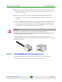
2.7.3
BreezeMAX PRO 2000 Cables
NOTE
The length of the Ethernet cable connecting the BreezeMAX PRO 2000 to the data equipment,
should not exceed 100 meters.
Use only Category 5E Ethernet cables from either Alvarion or any of the approved
manufacturers, listed in Table 2-8. Consult with Alvarion's specialists on the
suitability of other cables.
Table 2-8: Approved Category 5E Ethernet Cables
Manufacturer
Part Number
Superior Cables Ltd.
www.superior-cables.com
612098
HES Cabling Systems
H5E-00481
www.hescs.com
Teldor
www.teldor.com
8393204101
Southbay Holdings Limited
11th Fl., 15, Lane 347, Jong Jeng Rd.
Shin Juang City, Taipei County
Taiwan, R.O.C.
Attn: Eva Lin
Tel. 886-2-2832 3339
Fax. 886-2-2206 0081
E-mail: [email protected]
TSM2404A0D
GU-Tech., LLC . - A Member of OVIS GroupTel/Fax :
732 918 8221 Mobile: 718 909 4093
www.OVIS.COM.TW www.GU-TECH.COM
BreezeMAX PRO 2000 CPE
38
User Manual
Chapter 2 - Hardware Installation
ODU Antenna Alignment
In case of missing information in the manufacturer's WEB site (product
specifications, ordering issues, etc.), it is highly recommended to contact the
manufacturer's sales representative directly.
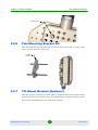
2.8
ODU Antenna Alignment
The ODU will provide the best link quality when its antenna is aligned in the
direction of the WiMAX base station. The optional SAU can be connected to the
ODU to provide status LED indications and assist with antenna alignment.
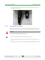
To align the ODU antenna using the SAU, follow these steps:
1
Remove the rubber sealing cover from the SAU port on the ODU.
2
Connect the SAU device to the SAU port. The PW (power) LED should turn on
to indicate that it is properly connected.
3
Point the ODU antenna in the general direction of the base station, then pan
the ODU back and forth while watching the link quality LEDs (see “SAU LED
Indicators” on page 18).
LED 9
LED 1
WLNK
Network Entry Complete
ET PW AL
4
Find the point where the link quality is best and secure the ODU in that
position. Verify that the SAU’s WLNK LED is on, indicating that the unit is
synchronized with the base station.
BreezeMAX PRO 2000 CPE
39
User Manual
Chapter 2 - Hardware Installation
ODU Antenna Alignment
NOTE
If all the SAU link quality LEDs are on, including LED 9 (red), the received signal strength is too
high. Move the ODU’s position so that only LEDs 1 to 8 are on.
5
Remove the SAU connection and replace the rubber sealing cover on the port.
6
Seal the SAU connector using tar seal or weatherproof tape to protect against
rain and moisture.
2.8.1
Align the WiMAX Antenna
After the BreezeMAX PRO 2000 unit has been mounted, connected, and its radio
is operating, the antenna must be accurately aligned to ensure optimum
performance on the wireless link. This alignment process is particularly important
for long-range links.
To start the alignment process, you can just point the antenna in the general
direction of the Access Unit’s (base station) antenna using binoculars or a
compass. For accurate alignment, you must monitor the signal strength LEDs as
the antenna moves horizontally.
The signal strength LEDs indicate the received radio signal strength for the link.
The more LEDs that turn on, the stronger the signal.
When you move the antenna during alignment, the radio signal from the remote
antenna can be seen to have a strong central main lobe and smaller side lobes.
The object of the alignment process is to set the antenna so that it is receiving the
strongest signal from the central main lobe.
BreezeMAX PRO 2000 CPE
40
User Manual
Chapter 2 - Hardware Installation
ODU Antenna Alignment
To align the antennas in the link, monitor the signal strength LEDs. For details
see Table 2-1. Perform the following procedure:
1
Pan the ODU horizontally back and forth while checking the LEDs, preferrably
with an SAU.
2
Find the point where the signal is strongest (refer to Table 2-1) and leave in
that position.
NOTE
Sometimes there may not be a central lobe peak because vertical alignment is too far off; only two
similar peaks for the side lobes are detected.
BreezeMAX PRO 2000 CPE
41
User Manual
Chapter
3
Initial Configuration
Chapter 3 - Initial Configuration
In This Chapter:
“Introduction” on page 44
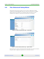
“The Advanced Setup Menu” on page 48
BreezeMAX PRO 2000 CPE
43
User Manual
Chapter 3 - Initial Configuration
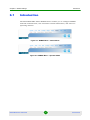
3.1
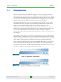
Introduction
Introduction
The BreezeMAX PRO 2000 offers a user-friendly web-based management interface
for the configuration of all the unit’s features. Any PC directly attached to the unit
can access the management interface using a web browser, such as Internet
Explorer (version 6.0 or above).
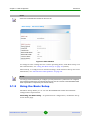
The web interface provides the options of Basic Setup or Advanced Setup.
The initial configuration steps can be made through the web-browser interface
using the default IP address.
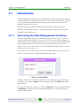
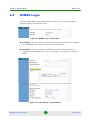
3.1.1
Accessing the Web Management Interface
The BreezeMAX PRO 2000 has the default IP address of 192.168.1.1 and the
subnet mask 255.255.255.0. If your PC is set to have an IP address assigned by
DHCP (Dynamic Host Configuration Protocol), you can connect immediately to the
web management interface. Otherwise, you must first check if your PC’s IP
address is set on the same subnet as the BreezeMAX PRO 2000 (that is, the PC’s
IP address starts 192.168.1.x).
In the web browser’s address bar, type the default IP address: http://192.168.1.1.
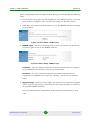
The web browser displays the BreezeMAX PRO’s login page.
Figure 3-1: Login Window
To log in, enter the user name and password, and click Login. For Admin mode,
the default user name is admin and the default password is admin. The home
page displays.
For Operator mode, the default user name is Operator and the default password
is oper1234. In Operator mode, additional parameters are available for more
detailed configuration.
BreezeMAX PRO 2000 CPE
44
User Manual
Chapter 3 - Initial Configuration
Introduction
NOTE
Admin user credentials are intended for the end user.
Figure 3-2: Main Window
To configure basic settings for the current operating mode, click Basic Setup. For
more information, see “Using the Basic Setup” on page 45 (below).
Alternatively, to configure more detailed settings, click Advanced Setup. For more
information, see “The Advanced Setup Menu” on page 48.
NOTE
It is strongly recommended that you configure your own password. If a password is not configured,
the management interface is not protected and anyone who can connects to the BreezeMAX PRO
2000 may be able to compromise your network security.
3.1.2
Using the Basic Setup
The Basic Setup allows you to run the BreezeMAX PRO 2000 with minimal
configuration requirements.
Launching the Basic Setup – To perform basic configuration, click Basic Setup
on the home page.
BreezeMAX PRO 2000 CPE
45
User Manual
Chapter 3 - Initial Configuration
Introduction
When configuring the unit through the Basic Setup, proceed through the following
steps:
1
For first-time setup, place the CD supplied by your WiMAX operator in the CD
drive of the PC. Navigate to the CD’s location using the “Browse” button.
2
Click Next; this enables the Basic Setup to copy the WiMAX operator’s settings
to the gateway.
Figure 3-3: Basic Setup - CD Directory
3
WiMAX Login – The Account Setting page sets the user name and password
required to gain access to the WiMAX network.
Figure 3-4: Basic Setup - WiMAX Login
Username – The user name required for network authentication, as supplied
by the WiMAX service provider. (Default: pseudo@realm)
Password – The user password required for network authentication, as
supplied by the WiMAX service operator. (Range: 1-32 characters; Default:
hello)
4
Apply Settings – When you click "Apply" the settings on the operator-supplied
CD are copied to the gateway, then the unit reboots and attempts to connect to
the specified WiMAX network.
The unit will prompt for confirmation of the Username and Password, click
“OK.”
BreezeMAX PRO 2000 CPE
46
User Manual
Chapter 3 - Initial Configuration
Introduction
Figure 3-5: Basic Setup- Apply Changes
5
The system will inform you when the configuration changes have taken effect
and will perform a two minute reboot.
Figure 3-6: Basic Setup - Setup Complete
6
After waiting approximately two minutes, you must type the IP address of the
unit (192.168.1.1) into your web browser to re-access the management
interface.
BreezeMAX PRO 2000 CPE
47
User Manual
Chapter 3 - Initial Configuration
3.2
The Advanced Setup Menu
The Advanced Setup Menu
The Advanced Setup menu provides access to all the configuration settings
available for the BreezeMAX PRO 2000. The advanced setup menu is available
both for operator and admin user credentials. Some of the menus are not
available to the admin user. The menus for both users are described.
Figure 3-7: Advanced Setup Home Page – Admin Mode
Figure 3-8: Advanced Setup Home Page – Operator Mode
Each primary menu item is summarized below with links to the relevant section in
this guide where configuration parameters are described in detail:
BreezeMAX PRO 2000 CPE
48
User Manual
Chapter 3 - Initial Configuration
The Advanced Setup Menu
System – Configures general device settings, see “System Settings” on page 50.
WAN – Configures WAN settings, see “WAN Settings” on page 71. (WAN
settings are only available in Operator mode.)
LAN – Configures LAN settings, see “LAN” on page 75.
NAT – Configures Network Address Translation settings, see “NAT” on page 78.
Firewall – Configures firewall settings, see “Firewall” on page 81.
Route – Displays static routing settings, see “Route” on page 84.
UPnP – Enables UPnP, see “UPnP” on page 85.
WiMAX – Configures the wireless connection status, see “WiMAX Settings” on
page 86.
VoIP – Configures VoIP SIP settings, see “VoIP Settings” on page 96.
WiFi – Configures 802.11 access point settings, see “WiFi Settings” on
page 112.
BreezeMAX PRO 2000 CPE
49
User Manual
Chapter
4
System Settings
Chapter 4 - System Settings
In This Chapter:
“Introduction” on page 52
“Host Name” on page 53
“System Status” on page 54
“Administrator Settings” on page 56
“Firmware Upgrade” on page 57
“Configuration Tools” on page 58
“System Time” on page 60
“TR069 Settings” on page 62
“System Log” on page 64
“Reset” on page 65
BreezeMAX PRO 2000 CPE
51
User Manual
Chapter 4 - System Settings
4.1
Introduction
Introduction
The BreezeMAX PRO 2000’s System menu allows you to perform general
management functions for the unit, including setting the system time, configuring
an access password, and upgrading the system software.
Through an easy to use web management interface the BreezeMAX PRO 2000 can
be configured to be a powerful wireless connection to any telecommunications
network.
NOTE
You can use the web browser interface to access the WAN IP address only if the BreezeMAX PRO
2000 already has an IP address that is reachable through your network.
The default IP address of the BreezeMAX PRO 2000 is 192.168.1.1. The CPE operates by default in
DHCP mode.
BreezeMAX PRO 2000 CPE
52
User Manual
Chapter 4 - System Settings
4.2
Host Name
Host Name
The gateway allows you to define a name that identifies your unit and the domain
name used by the local network. Setting a host name enables the web interface to
be accessed using an easy-to-remember name instead of its IP address.
NOTE
The Host Name settings are only available in Operator mode
Figure 4-1: System Host Name
Host Name – Enter the name chosen for the unit. (Default: cpe)
Domain Name – Enter the domain to which the unit is connected.
BreezeMAX PRO 2000 CPE
53
User Manual
Chapter 4 - System Settings
4.3
System Status
System Status
The system status page displays connectivity status information for the unit’s
WiMAX (WAN) and LAN interfaces, firmware and hardware version numbers, and
the number of clients connected to your network.
Figure 4-2: System Status
INTERNET – Displays WAN (WiMAX) connection status:
WAN IP – Displays the IP address assigned by the service provider.
Subnet Mask – Displays the WAN subnet mask assigned by the service
provider.
Gateway – Displays the WAN gateway address assigned by the service
provider.
Primary DNS – Displays the WAN primary DNS address.
Secondary DNS – Displays the WAN secondary DNS address.
Connection Type – Displays the connection type for the WAN. Either FIXED
for a static IP setting, or DHCPC for dynamic IP assignment.
Figure 4-3: System Status Gateway
GATEWAY – Display system IP settings, as well as DHCP, NAT and firewall status:
BreezeMAX PRO 2000 CPE
54
User Manual
Chapter 4 - System Settings
System Status
IP Address – Displays the unit’s IP address.
Subnet Mask – Displays the subnet mask.
DHCP Server – Displays the DHCP server status.
Firewall – Displays the firewall status.
Figure 4-4: System Status VoIP Status
VoIP STATUS - Displays the status of the connection of each of the phone lines.
Phone 1 Status – Displays the SIP status of phone line 1.
Phone 2 Status – Displays the SIP status of phone line 2.
Figure 4-5: System Status Information
INFORMATION – Displays the number of connected clients, as well as the unit’s
LAN and WAN MAC addresses:
Connected Clients – Displays the number of connected clients, if any.
Runtime Code Version – Displays the runtime code version.
LAN MAC Address – Displays the LAN MAC address.
LAN MTU Size – Sets the LAN maximum transmission unit size in bytes.
WAN MAC Address – Displays WAN MAC address.
WAN MTU Size – Sets the WAN maximum transmission unit size in bytes.
BreezeMAX PRO 2000 CPE
55
User Manual
Chapter 4 - System Settings
4.4
Administrator Settings
Administrator Settings
The Administrator Settings page enables you to change the default password for
management access to the BreezeMAX PRO 2000.
Figure 4-6: Setting a Password
Current Password – You need to first enter your current administrator
password to be able to configure a new one. (Admin Mode Default: admin;
Operator Mode Default: oper1234)
New Password – Enter a new administrator password. (Range: 3~12
characters)
Confirm New Password – Enter the new password again for verification.
(Range: 3~12 characters)
Auto-Logout Time – The time of inactivity after which the unit terminates a
web management session. (Default: 30 minutes; Range: 1~99 minutes)
BreezeMAX PRO 2000 CPE
56
User Manual
Chapter 4 - System Settings
4.5
Firmware Upgrade
Firmware Upgrade
The Firmware Upgrade page enables you to download new software to the unit. By
clicking the “Browse” button you can navigate to the directory on your PC or
network where the firmware is kept.
Figure 4-7: Firmware Upgrade
Firmware Update – Downloads an operation code file from the web
management station to the BreezeMAX PRO 2000 using HTTP. Use the Browse
button to locate the code file locally on the management station and click
Apply to proceed.
BreezeMAX PRO 2000 CPE
57
User Manual
Chapter 4 - System Settings
4.6
Configuration Tools
Configuration Tools
The Configurations Tools page allows you to restore factory default settings, or
save and restore the unit’s configuration settings to or from a file on the
management station.
NOTE
The Backup Settings/Restore Settings option is not available in Admin mode.
.
Figure 4-8: Configuration Tools
Restore Factory Default Configuration – Resets the unit to its factory
default settings.
Backup Settings/Restore Settings – When selected, prompts either to
backup the current configuration to a file, or select a previously backed up file
to restore to the unit.
When you select “Restore Factory Default Configuration” and click Apply, a
confirmation message displays. Click the Restore button to continue.
Figure 4-9: Restoring the Factory Default Configuration
BreezeMAX PRO 2000 CPE
58
User Manual
Chapter 4 - System Settings
Configuration Tools
When you select “Backup Settings/Restore Settings” and click Apply, the
following page displays.
Figure 4-10: Backup/Restore Settings
Backup Settings – Saves the current configuration settings to a file named
“nv.bin” on the web management station.
Restore Settings – Restores a saved configuration file to the unit. You can use
the Browse button to locate the file on the web management station.
BreezeMAX PRO 2000 CPE
59
User Manual
Chapter 4 - System Settings
4.7
System Time
System Time
The BreezeMAX PRO 2000 uses the Simple Network Time Protocol (SNTP) to set its
internal clock based on periodic updates from a time server. Maintaining an
accurate time on the device enables the system log to record meaningful dates and
times for event entries.
SNTP uses Greenwich Mean Time, or GMT (sometimes known as UTC) based on
the time at the Earth’s prime meridian, zero degrees longitude. To display a time
corresponding to your local time, you must select your time zone, for example
GMT-06.00, for Central Time (US and Canada.)
Figure 4-11: Setting the System Time
TIme Protocol – Select SNTP to enable the unit to set its internal clock based
on periodic updates from a time server. The unit acts as an SNTP client,
periodically sending time synchronization requests to a specified time server.
Alternatively, you can select “None” and set the time and date manually.
(Default: SNTP)
Time Server Address – The IP address of a time server that the unit attempts
to poll for a time update. (Default: 192.43.244.18)
Current Time (hh:mm:ss) – Displays the current time of the system clock.
New TIme (hh:mm:ss) – Sets the system clock to the time specified. The time
can only be set manually when the Time Protocol is set to “None.”
Current Date (yyyy:mm:dd) – Displays the current date of the system clock.
BreezeMAX PRO 2000 CPE
60
User Manual
Chapter 4 - System Settings
System Time
New Date (yyyy:mm:dd) – Sets the system clock to the date specified. The
date can only be set manually when the Time Protocol is set to “None.”
Set Time Zone – SNTP uses Greenwich Mean Time (GMT) based on the time at
the Earth’s prime meridian, zero degrees longitude. To display a time
corresponding to your local time, you must select your time zone from the
pull-down list. (Default: (GMT+08:00) Taipei)
BreezeMAX PRO 2000 CPE
61
User Manual
Chapter 4 - System Settings
4.8
TR069 Settings
TR069 Settings
The Technical Report 069 (TR069) protocol defines a specification for remote
management of CPE devices. The protocol uses HTTP for two-way communication
between the CPE device and an Auto Configuration Server (ACS), allowing service
providers to provide CPE configuration, software upgrades, and other service
functions for end-users.
The TR069 Settings page allows you to set up the basic TR069 connection
parameters.
NOTE
The TR069 Settings page is only available in Operator mode.
Figure 4-12: TR069 Settings
Enable Periodic Report – Enables the sending of TR069 reports from the CPE
to the ACS server. (Default: Enabled)
Periodic Report Interval – Sets the time interval for sending TR069 reports to
the ACS server. (Range: 0-65535 seconds; Default: 86400 seconds)
User Name – The CPE user name required for authentication during session
set up with the ACS server. (Default: admin)
Password – The CPE password required for authentication during session set
up with the ACS server. (Default: admin)
BreezeMAX PRO 2000 CPE
62
User Manual
Chapter 4 - System Settings
TR069 Settings
Connection Request URL – Specifies the URL required for an ACS server to
connect to the CPE.
Connection Request User Name – The user name required for an ACS server
to make a connection request to the CPE.
Connection Request Password – The password required for an ACS server to
make a connection request to the CPE.
ACS URL – Specifies the URL required for the CPE to connect to the ACS
server.
BreezeMAX PRO 2000 CPE
63
User Manual
Chapter 4 - System Settings
4.9
System Log
System Log
The System Log page allows you to display system event messages. The logged
messages can serve as a valuable tool for isolating device and network problems,
and also indicate if any unauthorized attempts have been made to gain access to
your network.
NOTE
The System Log page is only available in Operator mode.
Figure 4-13: System Logs
Syslog Level – Sets the minimum severity level for event logging. The system
allows you to limit the messages that are logged by specifying a minimum
severity level. Error message levels range from the most severe (Emergency) to
least severe (Debug). The message levels that are logged include the specified
minimum level up to the Emergency level. (Default: Info)
Download – Downloads the current log file to the web management station.
Clear – Deletes all entries in the current log file.
Refresh – Updates the displayed log entries on the web page.
NOTE
Log messages saved in the unit’s memory are erased when the device is rebooted.
BreezeMAX PRO 2000 CPE
64
User Manual
Chapter 4 - System Settings
4.10
Reset
Reset
The Reset page allows you to restart the device’s software.
Figure 4-14: Reset Page
Figure 4-15: Resetting the System,
Reset – Resets the unit. All current settings are retained.
NOTE
Resetting the system will cause you to lose your currently unsaved settings. After pressing “Reset”
you will be prompted to give confirmation that you really want to reset.
BreezeMAX PRO 2000 CPE
65
User Manual
Chapter
5
Gateway Configuration
Chapter 5 - Gateway Configuration
In This Chapter:
“Introduction” on page 68
“Operation Mode” on page 69
“WAN Settings” on page 71
“LAN” on page 75
“NAT” on page 78
“Firewall” on page 81
“Route” on page 84
“UPnP” on page 85
BreezeMAX PRO 2000 CPE
67
User Manual
Chapter 5 - Gateway Configuration
5.1
Introduction
Introduction
The information in this chapter covers the configuration options for the
BreezeMAX PRO 2000’s Internet gateway functions.
The BreezeMAX PRO 2000 provides comprehensive firewall features and NAT
isolation for Internet traffic passing from the WiMAX service provider to the local
network connected to the LAN ports. The DHCP server feature can assign IP
addresses for up to 32 local network PCs and wireless clients.
Figure 5-1: Gateway Settings Menu – Admin Mode
Figure 5-2: Gateway Settings Menu – Operator Mode
BreezeMAX PRO 2000 CPE
68
User Manual
Chapter 5 - Gateway Configuration
5.2
Operation Mode
Operation Mode
Sets appropriate parameters for forwarding data between the service provider’s
WiMAX network and the local network.
NOTE
The Operation Mode settings are only available in Operator mode
5.2.1
Operation Mode Settings
Specifies how various packets are forwarded to and from the WiMAX network to
the local network.
Figure 5-3: Operation Mode
Operation Mode – Specifies the mode for forwarding data packets from the
WiMAX network to the local network. Packets transmitted in ETH CS (Ethernet
conversion sublayer) mode contain an 802.3 header, packets transmitted in IP
CS mode do not contain this header. Only IP CS is available in the current
software release.
Data Transfer Mode – Sets the forwarding mode for sending data packets to
the WiMAX network. Bridge mode forwards packets based on Layer 2 MAC
addresses. Router mode forwards packets based on Layer 3 IP addresses.
Management Transfer Mode – Sets the forwarding mode for sending
management packets to the WiMAX network. Bridge mode forwards packets
based on Layer 2 MAC addresses. Router mode forwards packets based on
Layer 3 IP addresses.
VoIP Transfer Mode – Sets the forwarding mode for sending VoIP packets to
the WiMAX network. Bridge mode forwards packets based on Layer 2 MAC
addresses. Router mode forwards packets based on Layer 3 IP addresses.
BreezeMAX PRO 2000 CPE
69
User Manual
Chapter 5 - Gateway Configuration
5.2.2
Operation Mode
Management Settings
Sets the Differentiated Services Code Point (DSCP) value used in management
traffic between the BreezeMAX PRO 2000 and the WiMAX network. The DSCP
value in the IP header of data packets is used to give traffic priority treatment by
network equipment.
Figure 5-4: Operation Mode - Management Settings
Factory Defaults DSCP Classifier – The factory default Differentiated
Services Code Point (DSCP) value is 6.
Configured DSCP Classifier – The factory default Differentiated Services Code
Point (DSCP) value is 6. The configurable DSCP range is 0 to 63. If there is no
management connection to the BreezeMAX PRO 2000, the DSCP classifier
value will be changed by the system until a connection is successful.
Actual Used DSCP Classifier – The DSCP classifier value used for successful
management connection.
eCPE Manager Connection Status – Displays the current status of the
management connection; either Connected or Not Connected.
5.2.3
VoIP Settings
Enables the assignment of the SIP Proxy and Registrar Address by DHCP option
120.
Figure 5-5: Operation Mode - VoIP Settings
BreezeMAX PRO 2000 CPE
70
User Manual
Chapter 5 - Gateway Configuration
5.3
WAN Settings
WAN Settings
Select the WAN connection type used by your service provider and specify DNS
(Domain Name System) servers.
NOTE
The WAN settings are only available in Operator mode
Figure 5-6: WAN Settings
The unit can be connected to your ISP in one of the following ways:
Dynamic IP Address – Selects configuration for an Internet connection using
DHCP for IP address assignment. This is the default setting.
Static IP Address – Selects configuration for an Internet connection using a
fixed IP assignment.
NOTE
Static IP setting is not supported in the current software release.
L2TP – Selects configuration for an Internet connection using the Layer 2
Tunneling Protocol, an access protocol often used for virtual private networks.
PPPoE – Selects configuration for an Internet connection using the
Point-to-Point Protocol over Ethernet (PPPoE), a common connection method
used for DSL access.
NOTE
For the Dynamic IP Address (DHCP) option, the unit requires no further configuration. Selecting other
WAN types displays the parameters that are required for configuring the connection.
BreezeMAX PRO 2000 CPE
71
User Manual
Chapter 5 - Gateway Configuration
5.3.1
WAN Settings
Dynamic IP Address
For dynamic IP assignment from the service provider, the unit functions as a
Dynamic Host Configuration Protocol (DHCP) client. When enabled, no other
settings are required.
Figure 5-7: Dynamic IP Address
5.3.2
Static IP Settings
Selecting Static IP Address for the WAN type enables you to enter static IP settings
as assigned by the service provider.
NOTE
Static IP setting is not supported in the current software release.
Figure 5-8: Static IP Settings
IP Address assigned by your ISP – The IP address provided by your service
provider. Valid IP addresses consist of four decimal numbers, 0 to 255,
separated by periods.
Subnet Mask – Indicates the subnet mask, such as 255.255.255.0.
Gateway – The gateway IP address provided by your service provider.
BreezeMAX PRO 2000 CPE
72
User Manual
Chapter 5 - Gateway Configuration
5.3.3
WAN Settings
L2TP Settings
If your service provider supports Layer 2 Tunneling Protocol (L2TP) for your
Internet connection, configure the settings described below.
Figure 5-9: L2TP Settings
User Name – Enter your user name for connecting to the L2TP service, as
supplied by the service provider. (Range: 1-20 characters; Default: No name)
Password – Specify the password for your connection, as supplied by the
service provider. (Range: 1-20 characters; Default: No password)
L2TP Network Server – The IP address of the L2TP server, as specified by the
service provider.
Keep Alive – This option enables the unit to check periodically that the L2TP
connection is still operating. If the connection is found to be lost, the unit
automatically attempts to reconnect to the service provider. (Default: Enabled)
Keep Alive Time – The time period the unit waits before checking that the
L2TP connection is still operating. This parameter only applies when Keep
Alive is enabled. (Default: 60 seconds; Range: 10-180 seconds)
BreezeMAX PRO 2000 CPE
73
User Manual
Chapter 5 - Gateway Configuration
5.3.4
WAN Settings
PPPoE Settings
If your service provider supports Point-to-Point Protocol over Ethernet (PPPoE) for
your Internet connection, configure the settings described below.
Figure 5-10: PPPoE Settings
PPPoE Network Server – The IP address of the PPPoE server, as specified by
the service provider.
Keep Alive – This option enables the unit to check periodically that the PPPoE
connection is still operating. If the connection is found to be lost, the unit
automatically attempts to reconnect to the service provider. (Default: Enabled)
Keep Alive Time – The time period the unit waits before checking that the
PPPoE connection is still operating. This parameter only applies when Keep
Alive is enabled. (Default: 60 seconds; Range: 10-180 seconds)
BreezeMAX PRO 2000 CPE
74
User Manual
Chapter 5 - Gateway Configuration
5.4
LAN
LAN
The BreezeMAX PRO 2000 must have a valid IP address for management using a
web browser and to support other features. The unit has a default IP address of
192.168.1.1. You can use this IP address or assign another address that is
compatible with your existing local network. The unit can also be enabled as a
Dynamic Host Configuration Protocol (DHCP) server to allocate IP addresses to
local PCs.
5.4.1
LAN Settings
The BreezeMAX PRO 2000 includes a DHCP server that can assign temporary IP
addresses to any attached host requesting the service. Addresses are assigned to
clients from a common address pool configured on the unit. Configure an address
pool by specifying start and end IP addresses. Be sure not to include the unit's IP
address in the address pool range.
Figure 5-11: Local Area Network Settings
IP Address – The IP address of the unit. Valid IP addresses consist of four
decimal numbers, 0 to 255, separated by periods.The default setting is
192.168.1.1.
CAUTION
Changing the IP address of the BreezeMAX PRO 2000 will prompt a warning window and will
require a system reboot.
BreezeMAX PRO 2000 CPE
75
User Manual
Chapter 5 - Gateway Configuration
LAN
Figure 5-12: IP Address Warning
Subnet Mask – Indicates the local subnet mask is fixed as 255.255.255.0.
The Gateway acts as DHCP Server – Check this box to enable the DHCP
server.
IP Pool Starting/Ending Address – Specifies the start and end IP address of a
range that the DHCP server can allocate to DHCP clients. You can specify a
single address or an address range. Note that the address pool range is always
in the same subnet as the unit’s IP setting. (Default: 192.168.1.2 to
192.168.1.254)
Lease Time – Selects a time limit for the use of an IP address form the IP pool.
When the time limit expires, the client has to request a new IP address.
(Default: Half hour; Options: Half hour, one hour, two hours, half day, one
day, two days, one week, two weeks)
Local Domain Name – This optional parameter specifies the name of the
domain to which the unit is attached.
BreezeMAX PRO 2000 CPE
76
User Manual
Chapter 5 - Gateway Configuration
5.4.2
LAN
DHCP Client List
The DHCP Client List page enables you to see the MAC address of devices that are
currently connected to the unit and have been assigned an IP address by the
DHCP server.
Figure 5-13: DHCP Client List
BreezeMAX PRO 2000 CPE
77
User Manual
Chapter 5 - Gateway Configuration
5.5
NAT
NAT
Network Address Translation (NAT) is a standard method of mapping multiple
“internal” IP addresses to one “external” IP address on devices at the edge of a
network. For the BreezeMAX PRO 2000, the internal (local) IP addresses are the IP
addresses assigned to local PCs by the DHCP server, and the external IP address
is the IP address assigned to the WiMAX interface.
5.5.1
Virtual Server
Using the NAT Virtual Server feature, remote users can access different servers on
your local network using your single public IP address.
Remote users accessing services such as web or FTP at your local site through
your public IP address, are redirected (mapped) to other local server IP addresses
and TCP/UDP port numbers. For example, if you set Public Port to TCP/80 (HTTP
or web) and the Private IP/Port to 192.168.1.9/80, then all HTTP requests from
outside users are forwarded to 192.168.1.45 on port 80. Therefore, by just using
your external IP address provided by your ISP, Internet users can access the
services they need at the local addresses to which you redirect them.
The more common TCP service port numbers include: HTTP: 80, FTP: 21, Telnet:
23, and POP3: 110.
Figure 5-14: NAT Virtual Server
Private IP – The IP address of the server on the local Ethernet network. The
specified address must be in the same subnet as the BreezeMAX PRO 2000
and its DHCP server address pool. (Range: 192.168.1.1 to 192.168.1.254)
Private Port – Specifies the TCP/UDP port number used on the local server for
the service. (Range: 1-65535)
BreezeMAX PRO 2000 CPE
78
User Manual
Chapter 5 - Gateway Configuration
NAT
Type – Specifies the port type. (Options: TCP or UDP; Default: TCP)
Public Port – Specifies the public TCP/UDP port used for the service on the
WAN interface. (Range: 1-65535)
Enabled – Enables the virtual server mapping on the specified ports. (Default:
Disabled)
5.5.2
Port Mapping
Some applications, such as Internet gaming, video conferencing, Internet
telephony and others, require multiple connections. These applications cannot
work with Network Address Translation (NAT) enabled. If you need to run
applications that require multiple connections, use port mapping to specify the
additional public ports to be opened for each application.
Figure 5-15: NAT Port Mapping
Server IP – The IP address of the local server. (Range: 192.168.1.1 to
192.168.1.254)
Mapping Ports – Specifies the TCP/UDP ports that the application requires.
The ports may be specified individually, in a range, or a combination of both.
For example, 7, 11, 57, 72-96. (Range: 1-65535)
Enabled – Enables port mapping for the specified IP address. (Default:
Disabled)
BreezeMAX PRO 2000 CPE
79
User Manual
Chapter 5 - Gateway Configuration
5.5.3
NAT
DMZ
If you have a client PC that cannot run an Internet application properly from
behind the NAT firewall, you can open the client up to unrestricted two-way
internet access by defining a virtual-DMZ (virtual-demilitarized-zone) host.
Figure 5-16: DMZ
Enable – Enables the feature. (Default: Disabled)
IP Address of Virtual DMZ Host – Specifies the IP address of the virtual DMZ
host. (Range: 192.168.1.1 to 192.168.1.254; Default: 192.168.1.0)
NOTE
Adding a host to the DMZ may expose your local network to a variety of security risks, so only use this
option as a last resort.
BreezeMAX PRO 2000 CPE
80
User Manual
Chapter 5 - Gateway Configuration
5.6
Firewall
Firewall
The BreezeMAX PRO 2000 provides extensive firewall protection by restricting
connection parameters to limit the risk of intrusion and defending against a wide
array of common hacker attacks. However, for applications that require
unrestricted access to the Internet, you can configure a specific client/server as a
demilitarized zone (DMZ).
Figure 5-17: Firewall Setting
Enable – Enables the feature.
Disable – Disables the feature. (This is the default.)
5.6.1
Firewall Options
The BreezeMAX PRO 2000’s firewall enables access control of client PCs, blocks
common hacker attacks, including IP Spoofing, Land Attack, Ping of Death, Smurf
Attack, TCP null scan, ICMP defect, and TCP SYN flooding. The firewall does not
significantly affect system performance and it is best to leave it enabled to protect
your network.
Figure 5-18: Firewall Options
Enable Hacker Attack Protect – Network attacks that deny access to a
network device are called DoS attacks. DoS attacks are aimed at devices and
networks with a connection to the Internet. Their goal is not to steal
information, but to disable a device or network so users no longer have access
BreezeMAX PRO 2000 CPE
81
User Manual
Chapter 5 - Gateway Configuration
Firewall
to network resources. The Router protects against the following DoS attacks:
IP Spoofing, Land Attack, Ping of Death, Smurf Attack, TCP null scan, ICMP
defect, and TCP SYN flooding.
Discard PING from WAN side – Prevents pings on the unit’s WiMAX interface
from being routed to the network.
Discard to PING the Gateway – Prevents any response to a ping to the unit’s
IP address from the LAN.
Drop Port Scan – Prevents outside hackers form testing the TCP/UDP port
numbers on the unit for any services.
5.6.2
Client Filtering
You can block access to the Internet from clients on the local network by
specifying IP addresses and TCP/UDP port numbers. You can configure up to five
IP filters on the unit.
Figure 5-19: Client Filtering
Enable Client Filter – Enables client filtering for entries in the table.
(Default: Disabled)
IP – Specifies an IP address or range on the local network. (Range: 192.168.1.1
to 192.168.1.254)
Port – Specifies a TCP/UDP port number range to filter. (Range: 1-65535)
Type – Specifies the port type. (Options: TCP or UDP; Default: TCP)
Enable – Enables filtering for the table entry. (Default: Disabled)
BreezeMAX PRO 2000 CPE
82
User Manual
Chapter 5 - Gateway Configuration
5.6.3
Firewall
MAC Control
You can block access to the Internet from clients on the local network by MAC
addresses. You can configure up to 20 MAC address filters on the unit.
Figure 5-20: MAC Control
MAC Address Control – Enables the feature. (Default: Enabled)
Block Connect to Internet – Blocks Internet access for the specified MAC
address. (Default: Enabled)
MAC Address – Specifies a local PC MAC address.
Add – Adds a new MAC address to the filter table.
Delete – Removes a MAC address from the filter table.
BreezeMAX PRO 2000 CPE
83
User Manual
Chapter 5 - Gateway Configuration
5.7
Route
Route
The Routing Table displays the list of static routes on the unit.
Figure 5-21: Routing Table
Destination LAN IP – The IP address that identifies the IP subnet of the
remote network.
Subnet Mask – The mask that identifies the IP subnet of the remote network.
Gateway – The IP address of the router within the local IP subnet that
forwards traffic to the remote IP subnet.
Metric – Cost for the local interface. This cost is only used when routes are
imported by a dynamic routing protocol.
Interface – Indicates the local network interface on the unit.
BreezeMAX PRO 2000 CPE
84
User Manual
Chapter 5 - Gateway Configuration
5.8
UPnP
UPnP
UPnP (Universal Plug and Play Forum) provides inter-connectivity between devices
supported by the same standard.
Figure 5-22: UPnP
UPnP – Enables UpnP support on the unit. (Default: Disabled)
BreezeMAX PRO 2000 CPE
85
User Manual
Chapter
6
WiMAX Settings
Chapter 6 - WiMAX Settings
In This Chapter:
“Introduction” on page 88
“WiMAX Login” on page 89
“Subscriber Station Information” on page 92
“Antenna Setting” on page 93
“Advanced Configuration” on page 94
BreezeMAX PRO 2000 CPE
87
User Manual
Chapter 6 - WiMAX Settings
6.1
Introduction
Introduction
The BreezeMAX PRO 2000’s WiMAX menu enables you to configure WiMAX
network authentication, view subscriber station information, and select an
operating antenna.
Figure 6-1: WiMAX Menu – Admin Mode
Figure 6-2: WiMAX Menu – Operator Mode
BreezeMAX PRO 2000 CPE
88
User Manual
Chapter 6 - WiMAX Settings
6.2
WiMAX Login
WiMAX Login
The BreezeMAX PRO 2000’s WiMAX menu enables you to configure WiMAX
network settings and authentication.
Figure 6-3: WiMAX Login – Admin Mode
Username – The user name required for network authentication, as supplied
by the WiMAX service provider. (Default: pseudo@realm)
Password – The user password required for network authentication, as
supplied by the WiMAX service operator. (Range: 1-32 characters; Default:
hello)
Figure 6-4: Profile Setting – Operator Mode
BreezeMAX PRO 2000 CPE
89
User Manual
Chapter 6 - WiMAX Settings
WiMAX Login
GENERAL: Sets the operator ID, name and restriction.
Operator ID – A numeric string that uniquely identifies the WiMAX operator,
separated by colons.
Operator Names – The name of the WiMAX operator.
Operator Restriction – When Operator Restriction is selected the user can
only connect to the service provider specified in the profile. When not selected,
the operator specified in the profile is used when the network is detected,
otherwise the user can roam to other networks.
SCAN: Sets the scanned frequencies for the WiMAX profile.
Frequency – Specifies a center frequency to scan. (Range: 2000M~4000M)
Bandwidth – Specifies the bandwidth of the channel; 5, 7, or 10 MHz.
Currently only bandwidths 5 and 10 MHz are supported.
»
Add/Remove: Adds or Removes the specified frequency.
AUTHENTICATION: Sets WiMAX network authentication.
Enable Authentication – Enables authentication.
EAP Method – Selects the Extensible Authentication Protocol (EAP) method to
use for authentication. (Default: EAP-TTLS-MSCHAPV2)
»
EAP-TLS: Transport Layer Security. Provides for certificate-based and
mutual authentication of the client and the network. It relies on client-side
and server-side certificates to perform authentication and can be used to
dynamically generate user-based and session-based encryption keys to
secure subsequent communications between the user and the network. A
unique X.509 authentication certificate is included with the gateway
firmware.
»
EAP-TTLS-CHAP: Tunneled Transport Layer Security with
Challenge-Handshake Authentication Protocol (CHAP). This security
method provides for certificate-based, mutual authentication of the client
and network through an encrypted channel. Unlike EAP-TLS, EAP-TTLS
BreezeMAX PRO 2000 CPE
90
User Manual
Chapter 6 - WiMAX Settings
WiMAX Login
requires only server-side certificates. The CHAP protocol requires a user
name and password to be configured.
»
EAP-TTLS-MSCHAPV2: Tunneled Transport Layer Security with
Microsoft’s version 2 of CHAP. The MS-CHAP protocol requires a user name
and password to be configured.
EAP Mode – Defines the authentication mode.
»
device only: Specifies authentication using the unique X.509
authentication certificate included with the gateway firmware.
»
user-only: Specifies authentication using the configured user name and
password.
»
user-device: Specifies authentication using the configured user name and
password, and the unique X.509 authentication certificate.
Username – The user name required for EAP-TTLS authentication.
(Default: pseudo@realm)
Password – The user password required for EAP-TTLS authentication.
(Range: 1-32 characters; Default: hello)
MAC Address @ domain – A text string that is used to identify the
authentication realm for device authentication. This identity is used to proxy
an authentication request to another remote server. The authentication is then
performed using the unique X.509 authentication certificate included with the
device firmware. The identity string consists of the device MAC address
together with an operator-specified domain name. For example;
1f:20:30:10:4d:50@service-telecom.
BreezeMAX PRO 2000 CPE
91
User Manual
Chapter 6 - WiMAX Settings
6.3
Subscriber Station Information
Subscriber Station Information
The SSInfo page displays information about the software versions on the
BreezeMAX PRO 2000 unit.
Figure 6-5: Subscriber Station Information
Firmware Version – The version of software code running on the unit.
Driver Version – The version of the WiMAX chip driver software.
Library Version – The version of WiMAX library software.
Baseband Chip Version – The version of the WiMAX baseband chip.
RF Chip Version – The version of the WiMAX radio chip.
BreezeMAX PRO 2000 CPE
92
User Manual
Chapter 6 - WiMAX Settings
6.4
Antenna Setting
Antenna Setting
The BreezeMAX PRO 2000 does not have the option of using an external antenna
instead of the integrated antenna supplied with the unit. Be sure to always set the
Antenna Selection setting to “Omni.”
Figure 6-6: Antenna Setting
Antenna Selection – Set to use the integrated (Omni) antennas for WiMAX
communications. The External option is for lab purposes only. (Options:
Omni, External; Default: Omni)
BreezeMAX PRO 2000 CPE
93
User Manual
Chapter 6 - WiMAX Settings
6.5
Advanced Configuration
Advanced Configuration
The Advanced Configuration screen allows you to configure extended features for
the WiMAX connection.
NOTE
The Advanced Configuration page is only available in Operator mode
Figure 6-7: Advanced Configuration
Center Frequency – Configures the centre frequency used by the WiMAX
service.
Bandwidth – Configures the channel bandwidth used by the WiMAX service.
Hand Over Enable – Enable handoffs when moving between base stations.
ARQ Enable – The ARQ (Automatic Repeat reQuest) mechanism is an optional
part of the WiMAX MAC layer and a protocol for error control in data
transmission. When a packet error is detected, the transmitter is
automatically requested to resend the packet.
HARQ Enable – Hybrid ARQ (HARQ) is a variation of the ARQ error control
method. In standard ARQ, error-detection information (ED) bits are added to
data to be transmitted (such as cyclic redundancy check, CRC). In Hybrid
ARQ, forward error correction (FEC) bits are also added to the existing Error
Detection (ED) bits (such as Reed-Solomon code or Turbo code).
PKMv2 Enable – PKMv2 (Privacy Key Management version 2) is the standard
security solution for WiMAX networks. The security protocol provides mutual
authentication of the subscriber station and base station, as well as
BreezeMAX PRO 2000 CPE
94
User Manual
Chapter 6 - WiMAX Settings
Advanced Configuration
distributing traffic encryption keys. It is also used to transport EAP (Extensible
Authentication Protocol) messages. PKMv2 must not be enabled without
authentication being also enabled on the device. PKMv2 is automatically
enabled when authenticated mode is used.
DL MIMO Enable – Enables the use of downlink multiple-input and
multiple-output (DL MIMO) antennas.
PHS Enable – Enables payloader header suppression (PHS) a feature that
conserves link layer bandwidth by suppressing unnecessary packet headers
on upstream and downstream traffic flows.
BreezeMAX PRO 2000 CPE
95
User Manual
Chapter
7
VoIP Settings
Chapter 7 - VoIP Settings
In This Chapter:
“Introduction” on page 98
“SIP Account” on page 99
“SIP Setting” on page 101
“Dial Plan” on page 103
“Call Feature” on page 105
“Codecs” on page 107
“Call Block Setting” on page 109
“Phone Setting” on page 110
BreezeMAX PRO 2000 CPE
97
User Manual
Chapter 7 - VoIP Settings
7.1
Introduction
Introduction
Voice over Internet Protocol (VoIP) technology is a way of using the Internet to
make phone calls. Phone calls can be transmitted over the Internet by encoding a
voice call into data packets at one end and then decoding it back into voice calls at
the other end. This encoding and decoding is from a analog signal (your voice) into
a digital signal (data packets) and then back into an analog signal.
The BreezeMAX PRO 2000 uses Session Initiation Protocol (SIP) as the control
mechanism that sets up, initiates, and terminates calls between a caller and a
called party. The SIP messaging makes use of “Proxy,” “Redirect,” and
“Registration” servers to process call requests and find the location of called
parties across the Internet. When SIP has set up a call between two parties, the
actual voice communication is a direct peer-to-peer connection using the
standard Real-Time Protocol (RTP), which streams the encoded voice data across
the network.
You can make VoIP calls by connecting a regular phone to one of the BreezeMAX
PRO 2000’s RJ-11 Phone ports. You can also make VoIP calls from your computer
using a VoIP application with a simple microphone and computer speakers. Using
either method, VoIP provides an experience identical to normal telephoning.
Before using the VoIP Phone ports on the BreezeMAX PRO 2000, you must have
an account with a SIP service provider and configure the required parameters
through the web interface. The BreezeMAX PRO 2000 allows the two RJ-11 Phone
ports to be configured separately with different settings.
Figure 7-1: VoIP Menu – Admin Mode
Figure 7-2: VoIP Menu – Operator Mode
BreezeMAX PRO 2000 CPE
98
User Manual
Chapter 7 - VoIP Settings
7.2
SIP Account
SIP Account
From the VoIP SIP Account page, you can configure the basic SIP service
parameters for Phone 1 and Phone 2.
Figure 7-3: SIP Account Settings – Admin Mode
Figure 7-4: SIP Account Settings – Operator Mode
BreezeMAX PRO 2000 CPE
99
User Manual
Chapter 7 - VoIP Settings
SIP Account
Enable Proxy Outbound – Enables the use of proxy servers in the local
network to forward SIP requests. (Default: Disabled)
Always Proxy Outbound – Forces all SIP requests to be forwarded through
local proxy servers. (Default: Disabled)
Expire Time – The time the BreezeMAX PRO 2000 waits for a response from a
proxy server before a VoIP call fails. (Range: 60-65535 seconds; Default: 3600
seconds)
SIP Account – The SIP account user name.
Auth. User Name – An alphanumeric string that uniquely identifies the user
to the SIP server.
Auth. Password – An alphanumeric string that uniquely identifies the SIP
user’s permission rights.
Display Name – The name that is displayed to the other party during a call.
SIP Registrar – The IP address of the SIP registrar server. A registrar is a
server that accepts SIP register requests and places the information it receives
in those requests into the location service for the domain it handles.
SIP Registrar Port Number – The TCP port number used by the VoIP service
provider’s register server. (Range: 1-65535; Default: 5060)
Proxy Address – Address of the VoIP service provider SIP proxy server.
Proxy Port – The TCP port number used by the VoIP service provider’s SIP
proxy server. (Range: 1-65535; Default: 5060)
BreezeMAX PRO 2000 CPE
100
User Manual
Chapter 7 - VoIP Settings
7.3
SIP Setting
SIP Setting
From the VoIP SIP Setting page you can configure SIP parameter details.
NOTE
The SIP Setting page is only available in Operator mode
Figure 7-5: SIP Settings
RTP Packetization Time – Specifies a maximum amount of time for
transmission of a RTP data packet. (Options: 10, 20, 30 ms; Default: 20 ms)
RTP Port Base/Limit – The Real-time Transport Protocol (RTP) and Real-time
Control Protocol (RTCP) do not use specified port numbers. You can specify a
port range that the RTP and RTCP traffic can use. Enter the port Base and
Limit to define the range. (Range: 1024-65535)
Domain Name – The host portion of the SIP Uniform Resource Identifiers
(URIs) that are assigned to users in a network. The SIP domain name can
sometimes be different from the internal network domain name.
Stun Server – STUN (Simple Traversal of UDP through NAT (Network Address
Translation)) is a protocol that assists devices behind a NAT firewall or router
with packet routing. The problem of NAT firewalls can also be solved using a
proxy server to control SIP traffic. Specify the IP address and TCP port used by
the STUN server. (Default: 0.0.0.0:3478, “0.0.0.0” means not available; Port
Range: 0-65535)
BreezeMAX PRO 2000 CPE
101
User Manual
Chapter 7 - VoIP Settings
SIP Setting
DTMF – Enables the sending of dual-tone multi-frequency (touch tone) phone
signals over the VoIP connection. There are several methods to choose from:
»
No DTMF: The DTMF signals are not sent over the VoIP connection.
»
In-band Mode: The DTMF signals are sent over the RTP voice stream. In
the case when low-bandwidth codecs are used, the DTMF signals may be
distorted.
»
2833 Relay: Uses the RFC 2833 method to relay the DTMF signals over
the RTP voice stream without any distortion. (This is the default.)
»
Both In-band and 2833: Uses the best method depending on the called
party.
Invite Timeout – The time that the unit waits for a response to a SIP Invite
message before a call fails. If network connections are slow and many SIP calls
fail, you may need to increase this timeout value. (Range: 1-32 seconds;
Default: 12 seconds)
T.38 Option – Selects the method to use when sending fax messages over the
VoIP network from a fax machine connected to one of the RJ-11 Phone ports
on the BreezeMAX PRO 2000. (Default: Voice and T.38 Fax Relay)
»
T.38 Fax Relay: The SIP protocol sets up the VoIP call, then the T.38 Fax
Relay protocol sends the fax data over the network.
»
Voice and T.38 Fax Relay: Enables voice calls and faxes to be sent from
the Phone port connection. When a fax tone signal is detected on the port,
the T.38 Fax Relay standard is used instead of the voice codec.
»
Voice and Fax Pass Through: Enables voice calls and faxes to be sent
from the Phone port connection. For this option, fax signals are sent over
the VoIP network using the voice codec, just as if it were a voice call.
BreezeMAX PRO 2000 CPE
102
User Manual
Chapter 7 - VoIP Settings
7.4
Dial Plan
Dial Plan
A dial-plan string can be specified to control phone numbers dialed out through
the BreezeMAX PRO 2000. A dial plan describes the number and pattern of digits
that a user dials to reach a particular telephone number. Access codes, area
codes, specialized codes, and combinations of the number of digits dialed can all
be part of a dial plan. This enables a user to predefine dialling sequences that are
permitted. It can help transfer, check, limit phone numbers, and handle prefixes
to certain numbers.
The dial-plan string consists of a single digit rule. A typical example of a dial-plan
string is: [0123]xxxxxx.t
Three standard dial plans are defined; Call Transfer Key, New Call Key, and 3-way
Conference. Up to 10 other dial plans can be defined by the user.
Figure 7-6: Dial Plan Settings
BreezeMAX PRO 2000 CPE
103
User Manual
Chapter 7 - VoIP Settings
Dial Plan
The function of elements allowed in a dial plan are described in the table below:
Table 7-1: Dial Plan Functions
Element
Example
Description
x
xxxx
Represents a digit of any value ( 0 to 9)
that can be dialed on a phone. This
example has a rule with four digits of any
number.
.
xx.
Indicates zero or more occurrences of the
previous symbol. The example acts like a
wildcard, meaning any dialed phone
number of two or more digits is allowed.
0-9
01xx
Indicates dialed digits that must be
matched. This example only allows
four-digit numbers starting “01.”
[ ]
[125-8]
Limits a dialed digit to specified values or a
range of values. The example specifies
that only digits 1, 2, 5, 6, 7, and 8 are
permitted.
t
xx.t
The timeout indicator that can placed after
dialed digits or at the end of the dial-plan
string.
When a user dials a series of digits, the dial-plan rule is tested for a possible
match. If a match is made, the dialed sequence is transmitted. If no match is
made, the dialed number is blocked and the user will hear an error tone.
A dial-plan string cannot include spaces between elements. Dialed sequences that
are longer than specified in a dial-plan rule are truncated after the number of
specified digits. For example, if the dial-plan rule is “011x” and “0115678” is
dialed, only the digit sequence “0115” is transmitted.
BreezeMAX PRO 2000 CPE
104
User Manual
Chapter 7 - VoIP Settings
7.5
Call Feature
Call Feature
The BreezeMAX PRO 2000 allows you to configure several call features, such as
call waiting and call-forwarding. Other call features can be implemented by
pressing specific phone buttons or entering dial patterns.
The table below describes the various call features available.
NOTE
Some call features may be dependent on support at the SIP server. Check with the SIP service
provider.
Table 7-2: VoIP Call Features
Call Feature
Description
Activation
Call Hold
Places an active call on hold
for an unlimited period of time.
Press the “Flash,” “Flash Hook,” or “Hold” button on
the phone.
Call Waiting
If during a call there is another
incoming call, an alert tone is
heard.
This feature must first be enabled using the web
interface. You can place the active call on hold and
switch to the incoming call. You can switch between
the two calls by placing the active call on hold.
Call Switching
Calls two numbers, then
switches between them.
Dial the first number, then place it on hold. Dial the
key sequence “**” and wait until you hear the dial
tone, then dial the second number. Placing the active
call on hold switches to the other call. If the active
call is hung up, the phone rings again to activate the
other call.
Call Transfer
Transfers any received call to
another number you specify.
First place the received call on hold, then dial the
transfer key sequence “*#”. When you hear a dial
tone, enter the transfer phone number, then hang up.
Call Forward
Forwards an incoming call to
another number.
This feature can be configured using the web
interface. You can specify forwarding numbers for all
calls, when busy, or for no answer.
3-Way
Calls two numbers, then allows
all to talk together.
Dial the first number, then place it on hold. Dial the
key sequence “**” and wait until you hear the dial
tone, then dial the second number. When the second
call is active, dial “*3” to establish the three-way
conference.
Conference
BreezeMAX PRO 2000 CPE
105
User Manual
Chapter 7 - VoIP Settings
Call Feature
Figure 7-7: VoIP Call Features
Call Waiting – Enables a call waiting alert. If during a call there is another
incoming call, an alert tone is heard. You can place the active call on hold
(press the “Flash,” “Flash Hook,” or “Hold” button on the phone) and switch to
the incoming call. (Default: Disabled)
Call Waiting Timeout – The time a second incoming call waits before a “no
answer” message is sent. (Must be less than or equal to the value of Answer
Timeout; Default: 30 seconds)
Always Forward Phone Number – Another phone number to which all
incoming calls are forwarded.
On Busy Forward Phone Number – Another phone number to which
incoming calls are forwarded when the phone is busy.
No Answer Forward Phone Number – Another phone number to which
incoming calls are forwarded when there is no answer.
Call Forward No Answer Timeout – The time a call waits for an answer before
being forwarded to the No Answer Forward Phone Number. (Must be less than
or equal to the value of Answer Timeout; Default: 10 seconds)
BreezeMAX PRO 2000 CPE
106
User Manual
Chapter 7 - VoIP Settings
7.6
Codecs
Codecs
A codec (coder/decoder) is the way a voice analog signal is converted into a digital
bitstream to send over the network, and how it is converted back into an analog
signal at the receiving end. Codecs differ in the type of data compression that is
used to save network bandwidth and in the time delay caused in the signal. This
results in different voice quality experienced by the user.
The voice codecs in common use today have been standardized by the
International Telecommunication Union Telecommunication Standardization
Sector (ITU-T) and are identified by a standard number, such as G.711 or G.726.
The same codec must be supported at each end of a VoIP call to be able to encode
and decode the signal. Since devices in other networks may want to use different
codecs, the BreezeMAX PRO provides support for several common standards.
NOTE
The Codecs page is only available in Operator mode.
Figure 7-8: VoIP Codec Settings
Codec – Lists the codecs supported by the BreezeMAX PRO 2000. You can
enable specific codecs to use, or enable all. Alternatively, you may want to
disable certain codecs, such as high-bandwidth codecs, to preserve network
bandwidth.
»
PCMA (G711.aLaw): The ITU-T G.711 with A-law standard codec that uses
Pulse Code Modulation (PCM) to produce a 64 Kbps high-quality voice data
BreezeMAX PRO 2000 CPE
107
User Manual
Chapter 7 - VoIP Settings
Codecs
stream. This standard is used in Europe and most other countries around
the world.
»
PCMU (G711.uLaw): The ITU-T G.711 with mu-law standard codec that
uses Pulse Code Modulation (PCM) to produce a 64 Kbps high-quality voice
data stream. This standard is used in North America and Japan.
»
G723.1: The ITU-T G.723.1 standard low bitrate codec that uses MultiPulse Maximum Likelihood Quantization (MP-MLQ) and Algebraic Code
Excited Linear Prediction (ACELP) speech coding to produce data streams
of 6300 and 5300 bps.
»
G729ab: The ITU-T G.729ab standard codec that uses Conjugate
Structure Algebraic-Code Excited Linear Prediction (CS-ACELP) with
silence suppression to produce a low-bandwidth data stream of 8 Kbps.
Note that DTMF and fax tones do not transport reliably with this codec, it
is better to use G.711 for these signals.
»
G726-16/24/32/40: The ITU-T G.726 standard codecs that use Adaptive
Differential Pulse Code Modulation (ADPCM) to produce good-quality,
low-bandwidth data streams of either 16, 24, 32, or 40 Kbps.
Priority Codec List – The BreezeMAX PRO 2000 automatically negotiates the
codec to use for each called party. You can specify a priority for the codecs
that you prefer to use. For example, you may want to use a low-bandwidth
codec such as G729ab instead of a high-bandwidth G711 codec. Select a codec
in the list, then use the UP and DOWN buttons to set the priority. The
BreezeMAX PRO 2000 attempts to use the codec highest in the list before
trying the next lower one.
BreezeMAX PRO 2000 CPE
108
User Manual
Chapter 7 - VoIP Settings
7.7
Call Block Setting
Call Block Setting
The BreezeMAX PRO 2000 can block certain incoming and outgoing phone
numbers from making calls through the unit. You can specify up to 15 incoming
and 15 outgoing numbers to block.
NOTE
The Call Block Setting page is only available in Operator mode
Figure 7-9: Call Block Settings
Phone – Selects either VoIP port PHONE1 or PHONE2.
Outgoing – Blocks outgoing calls from the listed numbers. (Valid characters
0-9)
Incoming – Blocks incoming calls from the listed numbers. (Valid characters
0-9)
BreezeMAX PRO 2000 CPE
109
User Manual
Chapter 7 - VoIP Settings
7.8
Phone Setting
Phone Setting
The BreezeMAX PRO 2000 allows a national country setting to be enabled for the
region in which you are operating the unit, as well as the telecom service provider
currently listed as support by the unit.
The BreezeMAX PRO 2000 allows the timings for certain events on the VoIP phone
ports to be precisely configured. For example, you can specify how long a phone
will ring and how long a dial tone is heard on a phone.
The BreezeMAX PRO 2000 also enables the line delay to be specified for each
phone so that the caller’s voice echo is cancelled.
NOTE
The Phone Setting page is only available in Operator mode
Figure 7-10: Phone Settings
National Profile – Choose your country of operation for use of the VoIP
settings. Currently only, France, Israel, Japan, Korea, Spain, Taiwan, the UK
and the United States are supported.
Caller ID – The telecommunications standard that is supported for the
country of chosen operation. (Default: Disabled)
Answer Timeout – The time after which a no answer message is sent to the
caller. (Range: 1-300 seconds; Default: 60 seconds)
BreezeMAX PRO 2000 CPE
110
User Manual
Chapter 7 - VoIP Settings
Phone Setting
Dial Tone Timeout – The length of time a dial tone is heard on a connected
phone. (Range: 1-300 seconds; Default: 16 seconds)
Inter Digit Timeout – The maximum time delay allowed between each dialed
digit. When the time is exceeded, a call is made using the dialed digits. (Range:
1-300 seconds; Default: 2 seconds)
Line Echo Cancellation – Sets the delay time for voice echo cancellation. A
voice echo can be created on some two-wire phone loops, which becomes
increasingly louder and annoying when there is a long delay. If voice echo is a
problem during a call, you can adjust this parameter to try and reduce or
remove it. (Default: Enabled)
VAD/CNG – Voice Activity Detection/Comfort Noise Generator. VAD enables
the detection of periods of silence in the audio stream so that it is not
transmitted over the network. CNG then inserts artificial noise during silent
intervals in the audio stream. (Default: Enabled)
BreezeMAX PRO 2000 CPE
111
User Manual
Chapter
8
WiFi Settings
Chapter 8 - WiFi Settings
In This Chapter:
“Introduction” on page 114
“Wireless Settings” on page 115
“Wireless Security” on page 119
“MAC Authentication” on page 122
BreezeMAX PRO 2000 CPE
113
User Manual
Chapter 8 - WiFi Settings
8.1
Introduction
Introduction
The BreezeMAX PRO 2000 model for the 3.5 GHz WiMAX band includes an IEEE
802.11g radio interface for local Wi-Fi communications. The Wi-Fi set up pages
include configuration options for the radio signal characteristics and Wi-Fi
security.
Figure 8-1: WiFi Menu
BreezeMAX PRO 2000 CPE
114
User Manual
Chapter 8 - WiFi Settings
8.2
Wireless Settings
Wireless Settings
From the Wireless menu, click on Settings to configure the unit’s Wi-Fi radio
interface. The unit’s radio can operate in two modes, IEEE 802.11b & g and
802.11b only.
The IEEE 802.11g standard operates within the 2.4 GHz band at up to 54 Mbps.
Note that because the IEEE 802.11g standard is an extension of the IEEE
802.11b standard, it allows clients with 802.11b wireless network cards to
associate to an 802.11g access point.
Figure 8-2: Wireless Settings
Interface Status – Enables the Wi-Fi radio.
Country Code – Enables to select the parameter set (list of parameters per
country regulations) by which various parameters are defined. (Default: United
States)
Network Name (SSID) – The Service Set ID (SSID) that identifies the Wi-Fi
network. The SSID is case sensitive and can consist of up to 32 alphanumeric
characters. (Default: default)
Radio Channel – The radio channel used by the unit and its clients to
communicate with each other. This channel must be the same on the unit and
BreezeMAX PRO 2000 CPE
115
User Manual
Chapter 8 - WiFi Settings
Wireless Settings
all of its wireless clients. The available channel settings are limited by local
regulations. (Default: 1; Range: 1-11)
NOTE
If you experience poor performance, you may be encountering interference from another wireless
device. Try changing the channel, as this may eliminate interference and increase performance.
Channels 1, 6, and 11, as the three non-overlapping channels in the 2.4 GHz band, are preferred.
Auto Channel Select – Enables the unit to automatically select an available
radio channel. (Default: Enabled)
Working Mode – Selects the operating mode for the 802.11g radio. (Default:
B/G Mixed Mode)
»
B/G Mixed Mode: Both 802.11b and 802.11g clients can communicate
with the unit (up to 54 Mbps).
»
B Only Mode: Both 802.11b and 802.11g clients can communicate with the
unit, but 802.11g clients can only transfer data at 802.11b standard rates
(up to 11 Mbps).
Transmit Power – Adjusts the power of the radio signals transmitted from the
unit. The higher the transmission power, the farther the transmission range.
Power selection is not just a trade off between coverage area and maximum
supported clients. You also have to ensure that high-power signals do not
interfere with the operation of other radio devices in the service area. (Options:
Auto, Full, Min; Default: Auto)
Tx Data Rate – The maximum data rate at which the unit transmits unicast
packets on the Wi-Fi interface. The maximum transmission distance is
affected by the data rate. The lower the data rate, the longer the transmission
distance. (Default: Auto)
RTS Threshold (256~2432) – Sets the packet size threshold at which a
Request to Send (RTS) signal must be sent to a receiving station prior to the
sending the data frame. The unit sends RTS frames to a receiving station to
negotiate the sending of a data frame. After receiving an RTS frame, the station
sends a CTS (clear to send) frame to notify the unit that it can start sending
data. If a packet size equals or exceeds the RTS threshold, the RTS/CTS
(Request to Send / Clear to Send) mechanism will be enabled. Units
contending for the medium may not be aware of each other, and the RTS/CTS
BreezeMAX PRO 2000 CPE
116
User Manual
Chapter 8 - WiFi Settings
Wireless Settings
mechanism can solve this “Hidden Node Problem.” (Range: 256-2432 bytes:
Default: 2432 bytes)
CTS Protection Mode – When 802.11g and 802.11b clients operate together
in the same Wi-Fi network, there needs to be a mechanism that prevents
802.11b clients interfering with 802.11g transmissions. This is achieved by
sending 802.11b-compatible CTS (Clear to Send) or RTS/CTS (Request to
Send / Clear to Send) frames before each transmission. This mechanism
decreases the performance of 802.11g clients, but ensures that 802.11b
clients can communicate with the BreezeMAX PRO 2000. (Default:CTS Only)
»
Disable: If there are no 802.11b clients in the network, the protection
mode can be disabled.
»
CTS Only: The transmitting client sends only a CTS frame to prevent
others from accessing the medium. This mechanism is effective for most
networks with mixed 802.11g and 802.11b clients.
»
RTS/CTS: Both RTS and CTS frames must be exchanged before a client
can send data. There may be 802.11b clients in some networks that do not
detect the CTS frames from other stations. The full RTS/CTS exchange
should solve most connection problems, but it also has the greatest impact
on network performance.
Preamble Length – All IEEE 802.11 frames begin with an alternating pattern
of 1s and 0s called the preamble, which tells receiving stations that a frame is
arriving. This provides time for the receiving station to synchronize to the
incoming data stream. This parameter sets the length of the signal preamble
that is used at the start of a data transmission. Using a short preamble (96
microseconds) instead of a long preamble (192 microseconds) can increase
data throughput on the unit, but requires that all clients can support a short
preamble. (Default: Short)
»
Short: Sets the preamble to short for increased throughput.
»
Long: Sets the preamble to long. Using a long preamble ensures the unit
can support all 802.11b and 802.11g clients.
SSID Suppress – When enabled, the BreezeMAX PRO 2000 stops broadcasting
the configured SSID in its beacon signal. The unit is configured by default as
an “open system,” which broadcasts a beacon signal including the configured
SSID. Wireless clients with a configured SSID of “ANY” can read the SSID from
BreezeMAX PRO 2000 CPE
117
User Manual
Chapter 8 - WiFi Settings
Wireless Settings
the beacon, and automatically set their SSID for immediate connection to the
BreezeMAX PRO 2000. When enabled, the unit does not include its SSID in
beacon messages. This provides a basic level of security, since wireless clients
must be configured with the SSID to connect to the BreezeMAX PRO 2000.
Factory Default – Click the Reset button to set all the Wi-Fi settings to their
factory default values.
BreezeMAX PRO 2000 CPE
118
User Manual
Chapter 8 - WiFi Settings
8.3
Wireless Security
Wireless Security
The BreezeMAX PRO 2000 Wi-Fi interface is configured by default as an “open
system,” which broadcasts a beacon signal including the configured SSID.
Wireless clients with a configured SSID of “ANY” can read the SSID from the
beacon, and automatically set their SSID to allow immediate connection to the
wireless network.
To implement wireless network security, you have to employ two main functions:
Authentication – It must be verified that clients attempting to connect to the
network are authorized users.
Traffic Encryption – Data passing between the unit and clients must be
protected from interception and evesdropping.
For a more secure network, the BreezeMAX PRO 2000 can implement one of
several security mechanisms. The security mechanism employed depends on the
level of security required, the network and management resources available, and
the software support provided on wireless clients.
To configure wireless security click on Security.
Figure 8-3: Wireless Security
8.3.1
Wireless Security
There are eight security options available. When you select the security type in the
table, the required settings are displayed. The option “Open System” together with
encryption disabled is equivalent to no security, all clients will be able to
immediately connect to the Wi-Fi network.
The following sections describe the security options available for the BreezeMAX
PRO 2000 Wi-Fi network.
BreezeMAX PRO 2000 CPE
119
User Manual
Chapter 8 - WiFi Settings
8.3.2
Wireless Security
WEP Shared Key Security
Wired Equivalent Privacy (WEP) provides a basic level of security, preventing
unauthorized access to the network and encrypting data transmitted between
wireless clients and the BreezeMAX PRO 2000. WEP uses static shared keys
(fixed-length hexadecimal or alphanumeric strings) that are manually distributed
to all clients that want to use the network.
When enabled, you must configure at least one WEP key for the Wi-Fi interface
and all its clients
.
Figure 8-4: WEP Shared Key Security
Key 1 ~ Key 4 – Sets WEP key values. The user must first choose between
ASCII or Hexadecimal keys. At least one key must be specified. Each WEP key
has an index number. The selected key is used for authentication and
encryption on the Wi-Fi interface. Enter key values that match the key type
and length settings. (Default: Hex, 64 bits, no preset value)
»
Key Type: Specifies keys as either ASCII or Hexadecimal values.
»
Key Length: WEP keys can be set as 64, 128, or 152 bits in length.
»
Key: Specify keys as either 5, 13, or 16 alphanumeric characters, or 10,
26, or 32 hexadecimal digits, depending on the selected key length.
BreezeMAX PRO 2000 CPE
120
User Manual
Chapter 8 - WiFi Settings
Wireless Security
Default Key Setting – Sets the WEP key used for authentication and
encryption. (Range: 1-4; Default: 1)
8.3.3
WPA/WPA2 Security
The WPA and WPA2 modes use IEEE 802.1X as their basic framework for user
authentication and dynamic key management. IEEE 802.1X access security uses
Extensible Authentication Protocol (EAP) and requires a configured Remote
Authentication Dial-in User Service (RADIUS) authentication server to be
accessible in the enterprise network. If you select WPA or WPA2 mode, be sure to
configure the RADIUS settings displayed on the page.
The WPA-WPA2-Mixed mode is a transitional mode of operation for networks
moving from WPA security to WPA2. WPA-WPA2-Mixed mode allows both WPA
and WPA2 clients to associate to a common Wi-Fi interface.
.
Figure 8-5: WPA/WPA2 PSK Security
WPA Pre-Shared Key – The key required for WPA-PSK, WPA2-PSK, and
WPA-WPA2-Mixed-PSK modes. There are.two methods for key entry: An ASCII
string of 8~63 characters in length (0~9, A~F, including spaces), or 64
hexadecimal digits.
BreezeMAX PRO 2000 CPE
121
User Manual
Chapter 8 - WiFi Settings
8.4
MAC Authentication
MAC Authentication
Wireless clients can be authenticated for network access by checking their MAC
address against a local database configured on the BreezeMAX PRO 2000. You
can configure a list of up to 32 wireless client MAC addresses in the filter list to
either allow or deny network access.
.
Figure 8-6: MAC Authentication
System Default – Specifies the action for MAC addresses listed in the local
MAC Authentication Table.
»
Deny: Blocks access for all MAC addresses listed in the MAC
Authentication Table. Clients with MAC addresses not listed in the table
are permitted access.
»
Allow: Permits access for all MAC addresses listed in the MAC
Authentication Table. Clients with MAC addresses not listed in the table
are denied access.
BreezeMAX PRO 2000 CPE
122
User Manual
Chapter 8 - WiFi Settings
MAC Authentication
Local MAC Filter Settings – Adds new MAC addresses to the MAC
Authentication Table, or removes addresses currently listed in the table.
»
MAC Address: Physical address of a client. Enter six pairs of hexadecimal
digits separated by colons; for example, 00:90:D1:12:AB:89.
»
Permission: Select Add to list a new specified MAC address in the MAC
Authentication Table. Select Delete to remove the specified MAC address
from the table.
»
Update: Performs the Add or Delete action on the specified MAC address.
MAC Authentication Table – Displays current entries in the MAC filter
database.
BreezeMAX PRO 2000 CPE
123
User Manual
Chapter
A
Troubleshooting
Chapter A - Troubleshooting
In This Chapter:
This appendix provides a lists of things to check in case of problems before
contacting local Technical Support.
BreezeMAX PRO 2000 CPE
125
User Manual
Chapter A - Troubleshooting
Check the following before you contact local Technical Support.
1
If you cannot access the Internet from the PC, check the following:
»
If you cannot access the Internet, be sure your WIndows system is
correctly configured for TCP/IP. The IP settings should be set to “obtain an
IP address automatically.”
»
The WAN Type settings for the service provider may not be configured
correctly. Use the web interface to check that the WAN settings match
those provided by the service provider.
»
You may be out of the service area of the WiMAX base station. Check with
the WiMAX service provider for service coverage information.
»
If you cannot resolve the problem, check the System Status page of the web
interface and contact your WiMAX service provider.
2
If the management interface cannot be accessed using a web browser:
»
Be sure the management station is correctly configured for TCP/IP. The IP
settings should be set to “obtain an IP address automatically.”
»
Try a Ping command from the management station to the unit’s IP address
to verify that the entire network path between the two devices is
functioning correctly.
»
Check that the management station has a valid network connection and
that the Ethernet port that you are using has not been disabled.
»
Check the network cabling between the management station and the unit.
If the problem is not resolved, try using a different port or a different cable.
3
Forgot or Lost the Password
»
Set the unit to its default configuration by pressing the reset button on the
back panel for 5 seconds or more. Then use the default password “admin”
to access the management interface.
4
If all other recovery measures fail and the unit is still not functioning properly,
take either of these steps:
»
Reset the unit using the web interface, or through a power reset.
»
Reset the unit to its factory default configuration by pressing the reset
button on the back panel for 5 seconds or more see “IDU Hardware
BreezeMAX PRO 2000 CPE
126
User Manual
Chapter A - Troubleshooting
Description” on page 20. Then use the default password “admin” to access
the management interface.
Table A-1: Troubleshooting Chart
Ports
Description
IDU Power LED is Off
AC power adapter may be disconnected. Check
connections between the unit, the AC power adapter, and
the wall outlet.
IDU Power LED is Red
The unit has detected a system error. Reboot the unit to
try and clear the condition.
If the condition does not clear, contact your local dealer
for assistance.
SAU WiMAX LEDs are Off
Move the location of the unit.
Check with the WiMAX service provider for service
coverage information.
SAU WiMAX Signal LEDs are all on
Green and LED 9 is on Red
IDU LAN link LED is Off
The WiMAX receive signal strength is too high. Adjust the
direction the ODU is pointing until only LEDs 1 to 8 are
on.
Verify that the unit and attached device are powered on.
Be sure the cable is plugged into both the unit and
corresponding device.
Verify that the proper cable type is used and its length
does not exceed specified limits.
Check the cable connections for possible defects.
Replace the defective cable if necessary.
BreezeMAX PRO 2000 CPE
127
User Manual
Chapter
B
GNU License
Chapter B - GNU License
In This Chapter:
This appendix provides summary of the terms and conditions of use of the GNU
license that applies to the software on the BreezeMAX PRO 2000.
BreezeMAX PRO 2000 CPE
129
User Manual
Chapter B - GNU License
The GNU General Public License
This product includes copyrighted third-party software subject to the terms of the
GNU General Public License (GPL), GNU Lesser General Public License (LGPL), or
other related free software licences. The GPL code used in this product is
distributed WITHOUT ANY WARRANTY and is subject to the copyrights of one or
more authors. For details, refer to the section “The GNU General Public License”
below, or refer to the applicable licence as included in the source-code archive.
B.1
The GNU General Public License
GNU GENERAL PUBLIC LICENSE
Version 2, June 1991
Copyright (C) 1989, 1991 Free Software Foundation, Inc.
59 Temple Place, Suite 330, Boston, MA 02111-1307= USA
Everyone is permitted to copy and distribute verbatim copies of this license
document, but changing it is not allowed.
BreezeMAX PRO 2000 CPE
130
User Manual
Chapter B - GNU License
B.1.1
The GNU General Public License
Preamble
The licenses for most software are designed to take away your freedom to share
and change it. By contrast, the GNU General Public License is intended to
guarantee your freedom to share and change free software--to make sure the
software is free for all its users. This General Public License applies to most of the
Free Software Foundation's software and to any other program whose authors
commit to using it. (Some other Free Software Foundation software is covered by
the GNU Library General Public License instead.) You can apply it to your
programs, too.
When we speak of free software, we are referring to freedom, not price. Our
General Public Licenses are designed to make sure that you have the freedom to
distribute copies of free software (and charge for this service if you wish), that you
receive source code or can get it if you want it, that you can change the software
or use pieces of it in new free programs; and that you know you can do these
things.
To protect your rights, we need to make restrictions that forbid anyone to deny
you these rights or to ask you to surrender the rights. These restrictions translate
to certain responsibilities for you if you distribute copies of the software, or if you
modify it.
For example, if you distribute copies of such a program, whether gratis or for a
fee, you must give the recipients all the rights that you have. You must make sure
that they, too, receive or can get the source code. And you must show them these
terms so they know their rights.
We protect your rights with two steps: (1) copyright the software, and (2) offer you
this license which gives you legal permission to copy, distribute and/or modify the
software.
Also, for each author's protection and ours, we want to make certain that
everyone understands that there is no warranty for this free software. If the
software is modified by someone else and passed on, we want its recipients to
know that what they have is not the original, so that any problems introduced by
others will not reflect on the original authors' reputations.
Finally, any free program is threatened constantly by software patents. We wish to
avoid the danger that redistributors of a free program will individually obtain
patent licenses, in effect making the program proprietary. To prevent this, we have
made it clear that any patent must be licensed for everyone's free use or not
licensed at all.
BreezeMAX PRO 2000 CPE
131
User Manual
Chapter B - GNU License
The GNU General Public License
The precise terms and conditions for copying, distribution and modification
follow.
B.1.2
GNU GENERAL PUBLIC LICENSE TERMS AND
CONDITIONS FOR COPYING, DISTRIBUTION
AND MODIFICATION
This License applies to any program or other work which contains a notice placed
by the copyright holder saying it may be distributed under the terms of this
General Public License. The "Program", below, refers to any such program or
work, and a "work based on the Program" means either the Program or any
derivative work under copyright law: that is to say, a work containing the Program
or a portion of it, either verbatim or with modifications and/or translated into
another language. (Hereinafter, translation is included without limitation in the
term "modification".) Each licensee is addressed as "you".
Activities other than copying, distribution and modification are not covered by this
License; they are outside its scope. The act of running the Program is not
restricted, and the output from the Program is covered only if its contents
constitute a work based on the Program (independent of having been made by
running the Program). Whether that is true depends on what the Program does.
You may copy and distribute verbatim copies of the Program's source code as you
receive it, in any medium, provided that you conspicuously and appropriately
publish on each copy an appropriate copyright notice and disclaimer of warranty;
keep intact all the notices that refer to this License and to the absence of any
warranty; and give any other recipients of the Program a copy of this License along
with the Program.
You may charge a fee for the physical act of transferring a copy, and you may at
your option offer warranty protection in exchange for a fee.
You may modify your copy or copies of the Program or any portion of it, thus
forming a work based on the Program, and copy and distribute such modifications
or work under the terms of Section 1 above, provided that you also meet all of
these conditions:
You must cause the modified files to carry prominent notices stating that you
changed the files and the date of any change.
You must cause any work that you distribute or publish, that in whole or in part
contains or is derived from the Program or any part thereof, to be licensed as a
whole at no charge to all third parties under the terms of this License.
BreezeMAX PRO 2000 CPE
132
User Manual
Chapter B - GNU License
The GNU General Public License
If the modified program normally reads commands interactively when run, you
must cause it, when started running for such interactive use in the most ordinary
way, to print or display an announcement including an appropriate copyright
notice and a notice that there is no warranty (or else, saying that you provide a
warranty) and that users may redistribute the program under these conditions,
and telling the user how to view a copy of this
License. (Exception: if the
Program itself is interactive but does not normally print such an announcement,
your work based on the Program is not required to print an announcement.)
These requirements apply to the modified work as a whole. If identifiable sections
of that work are not derived from the Program, and can be reasonably considered
independent and separate works in themselves, then this License, and its terms,
do not apply to those sections when you distribute them as separate works. But
when you distribute the same sections as part of a whole which is a work based
on the Program, the distribution of the whole must be on the terms of this
License, whose permissions for other licensees extend to the entire whole, and
thus to each and every part regardless of who wrote it.
Thus, it is not the intent of this section to claim rights or contest your rights to
work written entirely by you; rather, the intent is to exercise the right to control
the distribution of derivative or collective works based on the Program.
In addition, mere aggregation of another work not based on the Program with the
Program (or with a work based on the Program) on a volume of a storage or
distribution medium does not bring the other work under the scope of this
License.
You may copy and distribute the Program (or a work based on it, under Section 2)
in object code or executable form under the terms of Sections 1 and 2 above
provided that you also do one of the following:
Accompany it with the complete corresponding machine-readable source code,
which must be distributed under the terms of Sections 1 and 2 above on a
medium customarily used for software interchange; or,
Accompany it with a written offer, valid for at least three years, to give any third
party, for a charge no more than your cost of physically performing source
distribution, a complete machine-readable copy of the corresponding source code,
to be distributed under the terms of Sections 1 and 2 above on a medium
customarily used for software interchange; or,
Accompany it with the information you received as to the offer to distribute
corresponding source code. (This alternative is allowed only for noncommercial
distribution and only if you received the program in object code or executable form
with such an offer, in accord with Subsection b above.)
BreezeMAX PRO 2000 CPE
133
User Manual
Chapter B - GNU License
The GNU General Public License
The source code for a work means the preferred form of the work for making
modifications to it. For an executable work, complete source code means all the
source code for all modules it contains, plus any associated interface definition
files, plus the scripts used to control compilation and installation of the
executable. However, as a special exception, the source code distributed need not
include anything that is normally distributed (in either source or binary form)
with the major components (compiler, kernel, and so on) of the operating system
on which the executable runs, unless that component itself accompanies the
executable.
If distribution of executable or object code is made by offering access to copy from
a designated place, then offering equivalent access to copy the source code from
the same place counts as distribution of the source code, even though third
parties are not compelled to copy the source along with the object code.
You may not copy, modify, sublicense, or distribute the Program except as
expressly provided under this License. Any attempt otherwise to copy, modify,
sublicense or distribute the Program is void, and will automatically terminate
your rights under this License. However, parties who have received copies, or
rights, from you under this License will not have their licenses terminated so long
as such parties remain in full compliance.
You are not required to accept this License, since you have not signed it.
However, nothing else grants you permission to modify or distribute the Program
or its derivative works. These actions are prohibited by law if you do not accept
this License. Therefore, by modifying or distributing the Program (or any work
based on the Program), you indicate your acceptance of this License to do so, and
all its terms and conditions for copying, distributing or modifying the Program or
works based on it.
Each time you redistribute the Program (or any work based on the Program), the
recipient automatically receives a license from the original licensor to copy,
distribute or modify the Program subject to these terms and conditions. You may
not impose any further restrictions on the recipients' exercise of the rights granted
herein. You are not responsible for enforcing compliance by third parties to this
License.
If, as a consequence of a court judgment or allegation of patent infringement or for
any other reason (not limited to patent issues), conditions are imposed on you
(whether by court order, agreement or otherwise) that contradict the conditions of
this License, they do not excuse you from the conditions of this License. If you
cannot distribute so as to satisfy simultaneously your obligations under this
License and any other pertinent obligations, then as a consequence you may not
distribute the Program at all. For example, if a patent license would not permit
BreezeMAX PRO 2000 CPE
134
User Manual
Chapter B - GNU License
The GNU General Public License
royalty-free redistribution of the Program by all those who receive copies directly
or indirectly through you, then the only way you could satisfy both it and this
License would be to refrain entirely from distribution of the Program.
If any portion of this section is held invalid or unenforceable under any particular
circumstance, the balance of the section is intended to apply and the section as a
whole is intended to apply in other circumstances.
It is not the purpose of this section to induce you to infringe any patents or other
property right claims or to contest validity of any such claims; this section has the
sole purpose of protecting the integrity of the free software distribution system,
which is implemented by public license practices. Many people have made
generous contributions to the wide range of software distributed through that
system in reliance on consistent application of that system; it is up to the
author/donor to decide if he or she is willing to distribute software through any
other system and a licensee cannot impose that choice.
This section is intended to make thoroughly clear what is believed to be a
consequence of the rest of this License.
If the distribution and/or use of the Program is restricted in certain countries
either by patents or by copyrighted interfaces, the original copyright holder who
places the Program under this License may add an explicit geographical
distribution limitation excluding those countries, so that distribution is permitted
only in or among countries not thus excluded. In such case, this License
incorporates the limitation as if written in the body of this License.
The Free Software Foundation may publish revised and/or new versions of the
General Public License from time to time. Such new versions will be similar in
spirit to the present version, but may differ in detail to address new problems or
concerns.
Each version is given a distinguishing version number. If the Program specifies a
version number of this License which applies to it and "any later version", you
have the option of following the terms and conditions either of that version or of
any later version published by the Free Software Foundation. If the Program does
not specify a version number of this License, you may choose any version ever
published by the Free Software Foundation.
If you wish to incorporate parts of the Program into other free programs whose
distribution conditions are different, write to the author to ask for permission.
For software which is copyrighted by the Free Software Foundation, write to the
Free Software Foundation; we sometimes make exceptions for this. Our decision
will be guided by the two goals of preserving the free status of all derivatives of our
free software and of promoting the sharing and reuse of software generally.
BreezeMAX PRO 2000 CPE
135
User Manual
Chapter B - GNU License
The GNU General Public License
NO WARRANTY
BECAUSE THE PROGRAM IS LICENSED FREE OF CHARGE, THERE IS NO
WARRANTY FOR THE PROGRAM, TO THE EXTENT PERMITTED BY APPLICABLE
LAW. EXCEPT WHEN OTHERWISE STATED IN WRITING THE COPYRIGHT
HOLDERS AND/OR OTHER PARTIES PROVIDE THE PROGRAM "AS IS"
WITHOUT WARRANTY OF ANY KIND, EITHER EXPRESSED OR IMPLIED,
INCLUDING, BUT NOT LIMITED TO, THE IMPLIED WARRANTIES OF
MERCHANTABILITY AND FITNESS FOR A PARTICULAR PURPOSE. THE ENTIRE
RISK AS TO THE QUALITY AND PERFORMANCE OF THE PROGRAM IS WITH
YOU. SHOULD THE PROGRAM PROVE DEFECTIVE, YOU ASSUME THE COST
OF ALL NECESSARY SERVICING, REPAIR OR CORRECTION.
IN NO EVENT UNLESS REQUIRED BY APPLICABLE LAW OR AGREED TO IN
WRITING WILL ANY COPYRIGHT HOLDER, OR ANY OTHER PARTY WHO MAY
MODIFY AND/OR REDISTRIBUTE THE PROGRAM AS PERMITTED ABOVE, BE
LIABLE TO YOU FOR DAMAGES, INCLUDING ANY GENERAL, SPECIAL,
INCIDENTAL OR CONSEQUENTIAL DAMAGES ARISING OUT OF THE USE OR
INABILITY TO USE THE PROGRAM (INCLUDING BUT NOT LIMITED TO LOSS OF
DATA OR DATA BEING RENDERED INACCURATE OR LOSSES SUSTAINED BY
YOU OR THIRD PARTIES OR A FAILURE OF THE PROGRAM TO OPERATE WITH
ANY OTHER PROGRAMS), EVEN IF SUCH HOLDER OR OTHER PARTY HAS
BEEN ADVISED OF THE POSSIBILITY OF SUCH DAMAGES.
END OF TERMS AND CONDITIONS
BreezeMAX PRO 2000 CPE
136
User Manual
Glossary
100BASE-TX
IEEE 802.3u specification for 100 Mbps Fast Ethernet over two pairs of
Category 5 or better UTP cable.
10BASE-T
IEEE 802.3 specification for 10 Mbps Ethernet over two pairs of Category 3 or
better UTP cable
Advanced Encryption
Standard (AES)
A strong encryption algorithm that implements symmetric key cryptography.
Authentication
The process to verify the identity of a client requesting network access. IEEE
802.11 specifies two forms of authentication: open system and shared key.
Auto-negotiation
Signalling method allowing each node to select its optimum operational mode
(speed and duplex mode) based on the capabilities of the node to which it is
connected.
Base Station
A WIMAX service provider’s equipment that is installed at a fixed location to
provide network connectivity for subscriber stations within a defined service
area.
Broadcast Key
Broadcast keys are sent to stations using 802.1X dynamic keying. Dynamic
broadcast key rotation is often used to allow the access point to generate a
random group key and periodically update all key-management capable
wireless clients.
Customer Premise
Equipment (CPE)
Customer Premise Equipment: Communications equipment that resides on
the customer's premises.
Domain Name System
(DNS)
A system used for translating host names for network nodes into IP
addresses.
Dynamic Host Control
Protocol (DHCP)
Dynamic Host Configuration Protocol: Provides a framework for passing
configuration information to hosts on a TCP/IP network. DHCP is based on
the Bootstrap Protocol (BOOTP), adding the capability of automatic allocation
of reusable network addresses and additional configuration options.
Ethernet
A popular local area data communications network, which accepts
transmission from computers and terminals.
Encryption
Data passing between the SU-A-EZ and clients can use encryption to protect
from interception and evesdropping.
Extended Service Set
(ESS)
Extended Service Set: More than one wireless cell can be configured with the
same Service Set Identifier to allow mobile users can roam between different
cells with the Extended Service Set.
Extensible Authentication
Protocol (EAP)
An authentication protocol used to authenticate network clients. EAP is
combined with IEEE 802.1X port authentication and a RADIUS authentication
server to provide “mutual authentication” between a client, the access point,
and the a RADIUS server
File Transfer Protocol
(FTP)
File Transfer Protocol: A TCP/IP protocol used for file transfer.
BreezeMAX PRO 2000 CPE
138
User Manual
Hypertext Transfer
Protocol (HTTP)
Hypertext Transfer Protocol: HTTP is a standard used to transmit and receive
all data over the World Wide Web.
IEEE 802.16e
A standard that provides mobile broadband wireless access using Scalable
Orthogonal Frequency Division Multiple Access (SOFDMA).
Local Area Network (LAN)
Local Area Network: A group of interconnected computer and support
devices.
MAC
Media Access Control: The lower of the two sub-layers of the data link layer
defined by the IEEE. The MAC sub-layer handles access to shared media,
such as whether token passing or contention will be used.
MAC Address
Standardized data link layer address that is required for every port or device
that connects to a LAN. Other devices in the network use these addresses to
locate specific ports in the network and to create and update routing tables
and data structures. MAC addresses are 6bytes long and are controlled by
the IEEE.
Network Time Protocol
(NTP)
NTP provides the mechanisms to synchronize time across the network. The
time servers operate in a hierarchical-master-slave configuration in order to
synchronize local clocks within the subnet and to national time standards via
wire or radio.
Orthogonal Frequency
Division Multiplexing
(OFDM)
Orthogonal Frequency Division Multiplexing: OFDM allows multiple users to
transmit in an allocated band by dividing the bandwidth into many narrow
bandwidth carriers.
Power Over Ethernet (PoE)
Power over Ethernet: A specification for providing both power and data to
low-power network devices using a single Category 5 Ethernet cable. PoE
provides greater flexibility in the locating of Wi²s and network devices, and
significantly decreased installation costs.
RTS Threshold
Transmitters contending for the medium may not be aware of each other.
RTS/CTS mechanism can solve this “Hidden Node Problem.” If the packet
size is smaller than the preset RTS Threshold size, the RTS/CTS mechanism
will NOT be enabled.
Service Set Identifier
(SSID)
An identifier that is attached to packets sent over the wireless LAN and
functions as a password for joining a particular radio cell; i.e., Basic Service
Set (BSS).
Session Key
Session keys are unique to each client, and are used to authenticate a client
connection, and correlate traffic passing between a specific client and the
AU-EZ.
Shared Key
A shared key can be used to authenticate each client attached to a wireless
network. Shared Key authentication must be used along with the 802.11
Wireless Equivalent Privacy algorithm.
Simple Network
Management Protocol
(SNMP)
Simple Network Management Protocol: The application protocol in the
Internet suite of protocols which offers network management services.
BreezeMAX PRO 2000 CPE
139
User Manual
Simple Network Time
Protocol (SNTP)
SNTP allows a device to set its internal clock based on periodic updates from
a Network Time Protocol (NTP) server. Updates can be requested from a
specific NTP server, or can be received via broadcasts sent by NTP servers.
Subscriber Station
A general term for a customer’s WIMAX terminal equipment that provides
connectivity with a base station.
Subscriber Unit Alignment
Unit
(SAU)
An optional device that provides additional assistance in aligning the ODU
antenna.
Trivial File Transfer
Protocol (TFTP)
Trivial File Transfer Protocol: A TCP/IP protocol commonly used for software
downloads.
UTP
Unshielded twisted-pair cable.
Wired Equivalent Privacy
(WEP)
Wired Equivalent Privacy: WEP is based on the use of security keys and the
popular RC4 encryption algorithm. Wireless devices without a valid WEP key
will be excluded from network traffic.
BreezeMAX PRO 2000 CPE
140
User Manual