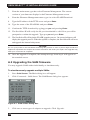
1
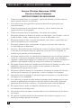
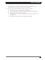
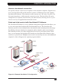
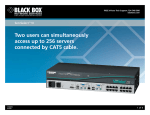
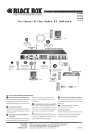
SERVSWITCH™ FAMILY
Welcome to the ServSwitch™ Family!
Thank you for purchasing a BLACK BOX® ServSelect IP! We appreciate your
business, and we think you’ll appreciate the many ways that your new ServSelect IP
will save you money, time, and effort.
That’s because our ServSwitch family is all about breaking away from the traditional,
expensive model of computer management. You know, the one-sizefits-all-even-if-itdoesn’t model that says, “One computer gets one user station, no more, no less.” Why
not a single user station (monitor, keyboard, and mouse) for multiple computers—even
computers of different platforms? Why not a pair of user stations, each of which can
control multiple computers? Why not multiple user stations for the same computer?
With our ServSwitch products, there’s no reason why not. We carry a broad line of
robust solutions for all these applications. Do you have just two PCs, and need an
economical alternative to keeping two monitors, keyboards, and mice on your desk?
Or do you need to share dozens of computers, including a mix of IBM® PC,
RS/6000®, Apple® Macintosh®, Sun Microsystems®, and SGI™ compatibles
among multiple users with different access levels? Does your switch have to sit
solidly on a worktable and use regular everyday cables? Or does it have to be
mounted in an equipment rack and use convenient many-to-one cables? No matter
how large or small your setup is, no matter how simple or how complex, we’re
confident we have a ServSwitch system that’s just right for you.
The ServSwitch™ family from BLACK BOX—the one-stop answer for all your
KVM switching needs!
*
This manual will tell you all about your new ServSelect IP, including how to install,
operate, and troubleshoot it. For an introduction to the ServSelect IP, see Chapter 2.
The ServSelect IP product codes covered in this manual are:
KV120A
KV120E
KV121A
KV212E
This manual also includes information about the ServSelect IP Software and the
Server Access Modules, which have their own manuals or installation guides:
KV125A
KV126A
KV127A
KV128A
And this manual also includes information about the ServSwitch™ Multi Z8 switch:
KV158A
1
SERVSELECT™ IP INSTALLER/USER GUIDE
FEDERAL COMMUNICATIONS COMMISSION AND
INDUSTRY CANADA
RADIO-FREQUENCY INTERFERENCE STATEMENTS
This equipment generates, uses, and can radiate radio-frequency energy and if not
installed and used properly, that is, in strict accordance with the manufacturer’s
instructions, may cause interference to radio communication. It has been tested and
found to comply with the limits for a Class A computing device in accordance with
the specifications in Subpart B of Part 15 of FCC rules, which are designed to
provide reasonable protection against such interference when the equipment is
operated in a commercial environment. Operation of this equipment in a residential
area is likely to cause interference, in which case the user at his own expense will be
required to take whatever measures may be necessary to correct the interference.
Changes or modifications not expressly approved by the party responsible for
compliance could void the user’s authority to operate the equipment.
This digital apparatus does not exceed the Class A limits for radio noise emission from
digital apparatus set out in the Radio Interference Regulation of Industry Canada.
Le présent appareil numérique n’émet pas de bruits radioélectriques dépassant les
limites applicables aux appareils numériques de la classe A prescrites dans le
Règlement sur le brouillage radioélectrique publié par Industrie Canada.
EUROPEAN UNION DECLARATION OF CONFORMITY
This equipment has been tested and found to comply with the limits for a class A
computing device in accordance with the specifications in the European standard
EN55022. These limits are designed to provide reasonable protection against
harmful interference. This equipment generates, uses and can radiate radiofrequency energy, and if not installed and used in accordance with the instructions,
might cause harmful interference to radio or television reception.
However, there is no guarantee that harmful interference will not occur in a
particular installation. If this equipment does cause interference to radio or television
reception, which can be determined by turning the equipment on and off, you can
correct the interference with one or more of the following measures:
(a) Reorient or relocate the receiving antenna.
(b) Increase the separation between the equipment and the receiver.
(c) Connect the equipment to an outlet on a circuit different from that to which the
receiver is connected.
(d) Consult the supplier or an experienced radio/TV technician for help.
2
COMPLIANCE STATEMENTS
Shielded cables must be used with this equipment to maintain compliance with radio
frequency energy emission regulations and ensure a suitably high level of immunity
to electromagnetic disturbances. This equipment has also been found to comply with
European standards EN50082 and EN60950.
Japanese Compliance Statement
Other Agency Approvals
UL 1950, CSA C22. 2 No. 950, IEC 950
Republic of Korea EMI Standard Certificate Number: E-F900-01-2012 (A)
TRADEMARKS USED IN THIS MANUAL
BLACK BOX and the
logo are registered trademarks, and ServSwitch,
ServSelect, and ServSelect IP are trademarks, of BLACK BOX Corporation.
Apple, Mac, and Macintosh are registered trademarks of Apple Computer, Inc.
IBM, PS/2, and RS/6000 are registered trademarks of International Business
Machines Corporation.
Microsoft, HyperTerminal, Windows, Windows NT, and Windows XP are
trademarks or registered trademarks of Microsoft Corporation in the United States
and/or other countries.
Sun and Sun Microsystems are registered trademarks of Sun Microsystems, Inc. in
the United States and other countries.
UL is a registered trademark of Underwriters Laboratories Inc.
Any other trademarks mentioned in this manual are acknowledged to be the property
of the trademark owners.
3
SERVSELECT™ IP INSTALLER/USER GUIDE
Normas Oficiales Mexicanas (NOM)
Electrical Safety Statement
INSTRUCCIONES DE SEGURIDAD
1.
Todas las instrucciones de seguridad y operación deberán ser leídas antes de
que el aparato eléctrico sea operado.
2.
Las instrucciones de seguridad y operación deberán ser guardadas para
referencia futura.
3.
Todas las advertencias en el aparato eléctrico y en sus instrucciones de
operación deben ser respetadas.
4.
Todas las instrucciones de operación y uso deben ser seguidas.
5.
El aparato eléctrico no deberá ser usado cerca del agua—por ejemplo, cerca de
la tina de baño, lavabo, sótano mojado o cerca de una alberca, etc.
6.
El aparato eléctrico debe ser usado únicamente con carritos o pedestales que
sean recomendados por el fabricante.
7.
El aparato eléctrico debe ser montado a la pared o al techo sólo como sea
recomendado por el fabricante.
8.
Servicio—El usuario no debe intentar dar servicio al equipo eléctrico más allá a
lo descrito en las instrucciones de operación. Todo otro servicio deberá ser
referido a personal de servicio calificado.
9.
El aparato eléctrico debe ser situado de tal manera que su posición no interfiera
su uso. La colocación del aparato eléctrico sobre una cama, sofá, alfombra o
superficie similar puede bloquea la ventilación, no se debe colocar en libreros o
gabinetes que impidan el flujo de aire por los orificios de ventilación.
10. El equipo eléctrico deber ser situado fuera del alcance de fuentes de calor como
radiadores, registros de calor, estufas u otros aparatos (incluyendo
amplificadores) que producen calor.
11. El aparato eléctrico deberá ser connectado a una fuente de poder sólo del tipo
descrito en el instructivo de operación, o como se indique en el aparato.
12. Precaución debe ser tomada de tal manera que la tierra fisica y la polarización
del equipo no sea eliminada.
13. Los cables de la fuente de poder deben ser guiados de tal manera que no sean
pisados ni pellizcados por objetos colocados sobre o contra ellos, poniendo
particular atención a los contactos y receptáculos donde salen del aparato.
14. El equipo eléctrico debe ser limpiado únicamente de acuerdo a las
recomendaciones del fabricante.
15. En caso de existir, una antena externa deberá ser localizada lejos de las lineas
de energia.
16. El cable de corriente deberá ser desconectado del cuando el equipo no sea
usado por un largo periodo de tiempo.
4
NOM STATEMENT
17. Cuidado debe ser tomado de tal manera que objectos liquidos no sean
derramados sobre la cubierta u orificios de ventilación.
18. Servicio por personal calificado deberá ser provisto cuando:
A:
B:
C:
D:
E:
El cable de poder o el contacto ha sido dañado; u
Objectos han caído o líquido ha sido derramado dentro del aparato; o
El aparato ha sido expuesto a la lluvia; o
El aparato parece no operar normalmente o muestra un cambio en su
desempeño; o
El aparato ha sido tirado o su cubierta ha sido dañada.
5
SERVSELECT™ IP INSTALLER/USER GUIDE
Contents
1. Specifications . . . . . . . . . . . . . . . . . . . . . . . . . . . . . . . . . . . . . . . . . . . . .9
2. Introduction . . . . . . . . . . . . . . . . . . . . . . . . . . . . . . . . . . . . . . . . . . . . . .10
2.1 Features and Benefits . . . . . . . . . . . . . . . . . . . . . . . . . . . . . . . . . . . . . . . . . . . . .10
2.2 Safety Precautions . . . . . . . . . . . . . . . . . . . . . . . . . . . . . . . . . . . . . . . . . . . . . . . .12
3. Installation . . . . . . . . . . . . . . . . . . . . . . . . . . . . . . . . . . . . . . . . . . . . . . .13
3.1 Getting Started . . . . . . . . . . . . . . . . . . . . . . . . . . . . . . . . . . . . . . . . . . . . . . . . . .13
3.2 Rackmounting Your ServSelect IP . . . . . . . . . . . . . . . . . . . . . . . . . . . . . . . . . .14
3.3 Installing the ServSelect IP . . . . . . . . . . . . . . . . . . . . . . . . . . . . . . . . . . . . . . . . .15
3.4 Setting Up Your ServSelect IP and Software . . . . . . . . . . . . . . . . . . . . . . . . . .19
4. Analog Port Operation . . . . . . . . . . . . . . . . . . . . . . . . . . . . . . . . . . . . . 20
4.1 Controlling Your System at the Analog Port . . . . . . . . . . . . . . . . . . . . . . . . . . .20
4.2 Viewing and Selecting Ports and Servers . . . . . . . . . . . . . . . . . . . . . . . . . . . . . .20
4.3 Navigating the OSD . . . . . . . . . . . . . . . . . . . . . . . . . . . . . . . . . . . . . . . . . . . . . .23
4.4 Configuring the OSD . . . . . . . . . . . . . . . . . . . . . . . . . . . . . . . . . . . . . . . . . . . . .24
4.5 Viewing and Disconnecting User Connections . . . . . . . . . . . . . . . . . . . . . . . . .31
4.6 Resetting Your Keyboard and Mouse . . . . . . . . . . . . . . . . . . . . . . . . . . . . . . . . .32
4.7 Displaying Version Information . . . . . . . . . . . . . . . . . . . . . . . . . . . . . . . . . . . . .32
4.8 Scanning Your System . . . . . . . . . . . . . . . . . . . . . . . . . . . . . . . . . . . . . . . . . . . .34
4.9 Broadcasting to Servers . . . . . . . . . . . . . . . . . . . . . . . . . . . . . . . . . . . . . . . . . . .36
5. Terminal Operations . . . . . . . . . . . . . . . . . . . . . . . . . . . . . . . . . . . . . . . 38
6. Troubleshooting . . . . . . . . . . . . . . . . . . . . . . . . . . . . . . . . . . . . . . . . . .40
6.1 Calling BLACK BOX . . . . . . . . . . . . . . . . . . . . . . . . . . . . . . . . . . . . . . . . . . . . .40
6.2 Shipping and Packaging . . . . . . . . . . . . . . . . . . . . . . . . . . . . . . . . . . . . . . . . . . .40
Appendix: FLASH Upgrades . . . . . . . . . . . . . . . . . . . . . . . . . . . . . . . . . . 41
A.1 Upgrading the ServSelect IP . . . . . . . . . . . . . . . . . . . . . . . . . . . . . . . . . . . . . . .41
A.2 Upgrading the SAM firmware . . . . . . . . . . . . . . . . . . . . . . . . . . . . . . . . . . . . . .42
6
CHAPTER 1: PRODUCT OVERVIEW
1. Specifications
During the course of this product’s lifetime, modifications might be made to its
hardware or firmware that could cause these specifications to change without notice.
Agency Approvals
EN55022 Class A, EN55024, EN61000-3-3, FCC15 Class A,
VCCI Class A, IEC950, EN60950, UL 1950/60950 third
edition, CSA C22.2 No. 950
Server Ports
Number
16
Interface Type
Proprietary composite of video, keyboard and mouse (to
SAM adapters)
Connectors
RJ-45
Sync Types
Separate horizontal and vertical
Plug and Play
DDC2B
Video Resolution
Analog Port Maximum 1600 x 1280 @ 75 Hz
Digital Port Maximum 1280 x 1024 @ 75 Hz
Configuration Port
Number
1
Interface Type
Serial RS-232, DTE
Connector
DB9 Female
Network Connection
Number
1
Interface Type
Ethernet: IEEE 802.3, 10BASE-T,
Fast Ethernet: IEEE 802.3U, 100BASE-T
Connector
RJ-45
Analog Port
Number
1
Interface Types
PS/2 and VGA
Connectors
(2) 6 pin MiniDIN, (1) HD15
Other Characteristics
Heat Dissipation
92 BTU/Hr
Airflow
8 cfm
Temperature
10º to 50º Celsius (50º to 122º Fahrenheit) operating
-20º to 60º Celsius (-4º to 140º Fahrenheit) nonoperating
Humidity
20 to 80% noncondensing operating
5 to 95% noncondensing nonoperating
Power
AC-input current rating
AC-input cable
100 to 240 VAC, 50 to 60 Hz (autosensing), 40 W maximum
1A
18 AWG three-wire cable, with a three lead IEC-320
receptacle on the power supply end and a country or region
dependent plug on the power resource end
25 W
Power Consumption
Size (HxWxD)
4.45 x 43.18 x 27.94 cm 1U form factor
(1.75 x 17.00 x 11.00 in)
Weight
3.6 kg (8 lb) without cables
7
SERVSELECT™ IP INSTALLER/USER GUIDE
2. Introduction
2.1 Features and Benefits
The BLACK BOX® ServSelect™ IP switches combine analog and digital technology
to provide flexible, centralized control of data center servers. This solution delivers
secure digital access and flexible server management from anywhere at any time.
NOTE:
Throughout the text, the word “appliance” is used generically to describe the ServSelect IP switch.
The ServSelect IP consists of a rackmountable keyboard, video and mouse (KVM)
switch configurable for analog or digital connectivity. Each ServSelect IP has
16 Analog Rack Interface (ARI) ports for connecting devices and operates over
standard LAN connections. Access servers across a 100BASE-T Ethernet connection
or directly through an analog port on the ServSelect IP for analog KVM connectivity
and administration. Video resolutions through the analog port can be up to 1600 x
1280 with an end-to-end cable length of up to 15 meters (50 feet). Digital users can
achieve video resolution of up to 1280 x 1024 with a cable length of up to 10 meters
(32 feet) between the ServSelect IP and the server.
ServSelect IP - KV120
Number
of
Digital
servers* users
Analog
user
128
1
1
128
2
1
ServSelect IP - KV121
*Maximum number of servers with a fully configured KV158A switch attached to each of the 16 ARI ports.
Figure 2-1. ServSelect IP Model Comparison
Server Access Modules
The Server Access Module (SAM) with CAT5 design dramatically reduces cable
clutter, while providing optimal digital display resolution and video settings. The
built-in memory of the SAM simplifies configuration by assigning and retaining
unique server names or Electronic ID (EID) numbers for each attached server. This
integrated intelligence enhances security and prevents unauthorized access to a
server through cable manipulation. The SAM is powered directly from the server
and provides Keep Alive functionality even if the ServSelect IP is not powered.
8
CHAPTER 2: INTRODUCTION
Access via network connection
No special software or drivers are required on the attached computers. Digital users
access the ServSelect IP and all attached systems via Ethernet from a PC running
ServSelect IP Software. This software resides on the user’s PC only. User PCs can
be located anywhere a valid network connection exists. The ServSelect IP can be
configured on a separate network from your data network, allowing access to your
servers even if your applications network is down.
Point and click control with ServSelect IP Software
The ServSelect IP Software is a cross-platform management application that allows you
to view and control the ServSelect IP and all attached servers. The ServSelect IP
Software provides secure authentication, data transfers and username/password storage.
By utilizing a browser interface for navigation with an intuitive split-screen interface,
this software provides you with a single point of access for your entire system. From
here, you can manage the ServSelect IP, install a new ServSelect IP or launch a video
session to a system server. Multiple servers can be accessed by one user; each additional
computer’s video will appear in a separate program window.
SAM
Adapter
SAM
Adapter
Switch
Switch
Rack of
Servers
Rack of
Servers
Critical Server
ServSelect IP
TCP/IP
Analog Connection
TCP/IP
IP Connections
Figure 2-2. Example ServSelect IP Configuration
9
SERVSELECT™ IP INSTALLER/USER GUIDE
2.2 Safety Precautions
To avoid potential video and/or keyboard problems when using these products:
•
If the building has 3-phase AC power, ensure that the computer and monitor are
on the same phase. For best results, they should be on the same circuit.
•
Use only BLACK BOX-supplied cable to connect computers and KVM switches.
To avoid potentially fatal shock hazard and possible damage to equipment, please
observe the following precautions:
•
Do not use a 2-wire extension cord in any BLACK BOX product configuration.
•
Test AC outlets at the computer and monitor for proper polarity and grounding.
•
Use only with grounded outlets at both the computer and monitor. When using
a backup power supply (UPS), power the computer, the monitor and the appliance off the supply.
NOTE:
The AC inlet is the main disconnect.
Rackmount safety considerations
•
Elevated Ambient Temperature: If the equipment is installed in a closed rack
assembly, the operation temperature of the rack environment may be greater than
room ambient. Use care not to exceed the rated maximum ambient temperature of
the equipment.
•
Reduced Air Flow: Installation of the equipment in a rack should be such that the
amount of airflow required for safe operation of the equipment is not compromised.
•
Mechanical Loading: Mounting of the equipment in the rack should be such
that a hazardous condition is not achieved due to uneven mechanical loading.
•
Circuit Overloading: Consideration should be given to the connection of the
equipment to the supply circuit and the effect that overloading of circuits might
have on overcurrent protection and supply wiring. Consider equipment nameplate ratings for maximum current.
•
Reliable Earthing: Reliable earthing of rackmounted equipment should be
maintained. Pay particular attention to supply connections other than direct
connections to the branch circuit (for example, use of power strips).
10
CHAPTER 3: INSTALLATION
3. Installation
The ServSelect® IP system requires that the ServSelect IP Software be installed prior
to use. ServSelect IP Software allows you to view and control a server attached to
the appliance system, configure and maintain the system and prevent unauthorized
access to the appliance via IP connection.
NOTE:
The analog port does not require the ServSelect IP Software for operation. The analog port uses
the On-Screen Display (OSD). For more information, see Chapter 4.
The ServSelect IP system uses Ethernet networking infrastructure and TCP/IP protocol
to transmit keyboard, video and mouse information between operators and connected
computers. Although 10BASE-T Ethernet may be used, a dedicated, switched
100BASE-T network provides improved performance.
3.1 Getting Started
Before installing your ServSelect IP appliance, refer to the following list to ensure
you have all items that shipped with the appliance as well as other items necessary
for proper installation. The KV120/121A models ship with power input cords
appropriate for North America. The KV120/121E models ship with power input
cords appropriate for Europe.
Supplied with the ServSelect IP
•
ServSelect IP unit
•
Power cord
•
Rackmounting kit
•
One straight-through null modem serial cable
•
ServSelect IP Installer/User Guide
•
ServSelect IP Software Installer/User Guide
•
ServSelect IP Quick Installation Guide
Additional items needed
•
One SAM per attached server or switch
Setting up your network
The ServSelect IP system uses IP addresses to uniquely identify the appliances and
the computers running ServSelect IP Software. The ServSelect IP appliance supports
both BootP (a subset of DHCP) and static IP addressing. BLACK BOX®
11
SERVSELECT™ IP INSTALLER/USER GUIDE
recommends that IP addresses be reserved for each unit and that they remain static
while the appliances are connected to the network.
3.2 Rackmounting Your ServSelect IP
Your ServSelect IP appliance ships with rackmounting brackets for easy integration
into your rack. Before installing the appliance and other components in the rack
cabinet, stabilize the rack in a permanent location. Install your equipment starting at
the bottom of the rack cabinet, then work to the top. Avoid uneven loading or
overloading of rack cabinets.
To install the 1U switch mounting bracket:
1.
Line up the holes in the “long side” of the kit’s side brackets with the screw
holes in the switch.
2.
With a Phillips screwdriver, fasten the mounting brackets to the switch using
two 8/32" x 1/2" pan head screws on each side.
3.
Attach the four cage nuts or clip nuts to the rackmounting flange of the rack
cabinet so that the nut is positioned on the inside of the rack.
4.
Mount the switch assembly to the rack cabinet by matching the holes in the “short
side” of each bracket to an appropriate set of matching holes on your rack
cabinet. Next, insert the combination hex head screws through the slots in the
bracket and the holes in the mounting rail, then into the cage nuts or clip nuts.
Figure 3-1. ServSelect IP Horizontal Installation
12
CHAPTER 3: INSTALLATION
3.3 Installing the ServSelect IP
Figure 3.2 illustrates one possible configuration for your ServSelect IP appliance.
Follow the detailed set of procedures following Figure 3.2 to successfully install
your appliance.
Network
Digital User
one user for the KV120A or
two users for the KV121A
Configuration Port for
updating firmware
ServSelect IP Appliance
ARI
Port
Power Cord
Servers 2-16
Local Analog
User
SAM Adaptor
PS/2, USB and
Sun adaptors are
available
Server 1
Figure 3-2. Basic ServSelect IP Configuration
CAUTION:
To reduce the risk of electric shock or damage to your equipment- Do not disable the power cord grounding plug. The grounding plug is an important safety feature.
- Plug the power cord into a grounded (earthed) outlet that is easily accessible at all times.
- Disconnect the power from the unit by unplugging the power cord from either the electrical
outlet or the unit.
13
SERVSELECT™ IP INSTALLER/USER GUIDE
To install the ServSelect IP hardware:
1.
Connect a terminal or PC running terminal emulation software (such as
HyperTerminal™) to the configuration port on the back panel of the appliance
using an RS-232 DB9 null modem cable. The terminal should be set to
9600 bps, 8 data bits, 1 stop bit, no parity and no flow control.
2.
Plug the supplied power cord into the back of the appliance and then into an
appropriate power source.
3.
When you turn on the power, the Power indicator on the front of the unit will
blink for 30 seconds while performing a self-test. Approximately 10 seconds after
it stops blinking, press the Enter key to access the main menu.
To configure the ServSelect IP hardware:
1.
You will see the Terminal Applications menu with six options. Select option 1,
Network Configuration.
Figure 3-3. Network Configuration Menu
2.
Select option 1 to set your network speed. When possible, you should set your
connection manually without relying on the auto negotiate feature. Once you
enter your selection, you will be returned to the Network Configuration menu.
3.
Select option 2 and specify if you are using a static or BootP IP address. Use a
static IP address for ease of configuration. If you are using a BootP address,
please configure your BootP server to provide an IP address to the appliance, skip
step 4 and continue to the next procedure.
4.
Select options 3-5 from the Terminal Applications menu, in turn, to finish
configuring your appliance for IP address, Netmask and Default Gateway. Once
this is completed, type a Ø to return to the main menu.
14
CHAPTER 3: INSTALLATION
To adjust the mouse acceleration:
Before a server can be connected to the ServSelect IP, an adjustment to mouse
acceleration must be made. Use the default Microsoft® Windows® PS/2® mouse
driver for all attached Microsoft Windows systems attached to the appliance.
For Microsoft Windows NT® (using default drivers):
1.
From the desktop, select Start - Settings - Control Panel - Mouse.
2.
Click on the Motion tab.
3.
Set the pointer speed to Slow. You will need to set this for any Windows NT user
account that will be accessing the Windows NT system through the appliance.
For Microsoft Windows 2000/Windows XP®:
1.
From the desktop, select Start - Settings - Control Panel - Mouse.
2.
Click on the Motion tab.
3.
Set the Acceleration setting to None and the speed setting to the default of 50%.
To connect a SAM adapter to each server:
1.
Locate the SAM adaptors for your ServSelect IP unit.
2.
Attach the appropriately color-coded cable ends to the keyboard, monitor and
mouse ports on the first server you will be connecting to the unit.
3.
Attach one end of the CAT5 cabling that will run between your SAM and
ServSelect IP unit to the RJ-45 connector on the SAM adapter.
4.
Connect the other end of the CAT5 cable to the desired ARI port on the back of
your ServSelect IP unit.
5.
Repeat steps 2-4 for all servers you wish to attach.
NOTE:
When connecting a Sun SAM adapter, you must use a multi-sync monitor to accommodate Sun
computers that support both VGA and sync-on-green or composite sync.
15
SERVSELECT™ IP INSTALLER/USER GUIDE
To add a KV158A ServSwitch® Multi Z8 switch:
You can add a KV158A ServSwitch Multi Z8 to the ServSelect IP system. In a
cascaded system, each ARI port will accommodate up to eight servers.
ServSelect IP Appliance
Server Access Modules
(KV125 - KV128)
PS/2, USB and Sun
cables versions are
available
KV158A ServSwitch
Local Analog
User
Server 1
Figure 3-4. ServSelect IP Configuration with a Legacy KVM Switch
1.
Mount the Z8 into your rack cabinet. Locate a length of CAT5 cabling to
connect your appliance to the SAM for your Z8.
2.
Attach one end of the CAT5 cabling to the RJ-45 connector on the SAM.
3.
Connect the other end of the CAT5 cable to a port on the back of your
ServSelect IP.
4.
Attach the keyboard, monitor and mouse connectors of the SAM to a user port
on your Z8.
5.
Connect the servers to your Z8 according to the instructions in the Z8’s manual.
6.
Power cycle the Z8 to enable the cascade code.
7.
Repeat steps 2-6 for all Z8s you want to attach to your system.
16
CHAPTER 3: INSTALLATION
To connect the network and turn on your ServSelect IP:
1.
Connect your network cable from the LAN port on the rear of the ServSelect IP
appliance to your network.
2.
The components in the ServSelect IP system may be turned on in any order.
However, since the SAMs are powered by the servers, turn on the servers
first and then turn on all attached systems for the most efficient startup.
3.4 Setting Up Your ServSelect IP and Software
See the ServSelect IP Software Installer/User Guide that ships with your appliance.
The ServSelect IP system has a local analog port that allows you to attach a monitor
and a PS/2 keyboard and mouse to the back of the unit. First, set up your servers at
the analog port via the OSD before proceeding to use the ServSelect IP Software to
finish configuring your system. Proceed to Chapter 4 in this installer/user guide for
detailed instructions on the OSD setup and configuration. Once your servers are
named, you will want to use a digital station to configure the ServSelect IP
Software. See the ServSelect IP Quick Installation Guide for an overview of the
hardware and software installation procedure.
17
SERVSELECT™ IP INSTALLER/USER GUIDE
4. Analog Port Operation
4.1 Controlling Your System at the Analog Port
The ServSelect® IP includes a local analog port on the back of the unit that allows you to
connect a monitor and a PS/2 keyboard and mouse for direct analog access. The
appliance uses the OSD, which utilizes intuitive menus to configure your system and
select computers.
4.2 Viewing and Selecting Ports and Servers
Use the OSD Main dialog box to view, configure and control servers in the
ServSelect IP system. View your servers by name, port or by the unique Electronic
ID number (EID) embedded in each SAM. You will see an OSD-generated port list
by default when you first launch the OSD.
The Port column indicates the ARI port to which a server is connected. If you
connect a legacy KVM switch to the appliance, the port numbering displays the ARI
port first, then the switch port to which the server is connected. For example, in
Figure 4-1, servers 04-03 and 01-02 are connected to switches.
To access the Main dialog box:
Press Print Screen to launch the OSD. The Main dialog box appears.
Figure 4-1. Example of Configured Main Dialog Box
NOTE:
You can also press the Control key twice within one second to launch the OSD. You can use this
key sequence in any place you see Print Screen throughout this installer/user guide.
18
CHAPTER 4: ANALOG PORT OPERATION
Viewing the status of your appliance
The status of the servers in your system is indicated in the right columns of the Main
dialog box. The following table describes the status symbols.
OSD Status Symbols
Symbol Description
SAM is online (green circle).
SAM is offline or is not operating properly.
Connected switch is online.
Connected switch is offline or is not operating properly.
SAM is being upgraded (yellow circle).
SAM is being accessed by the indicated user channel.
SAM is blocked by the indicated user channel. For instance, in Figure 4-1, user B
is viewing Forester, but is blocking access to Acton, Barrett and Edie which are
connected to the same SAM chain.
Selecting servers
Use the Main dialog box to select servers. When you select a server, the appliance
reconfigures the keyboard and mouse to the proper settings for that server.
To select servers:
Double-click the server name, EID or port number.
-orIf the display order of your server list is by port (Port button is depressed), type the
port number and press Enter.
-orIf the display order of your server list is by name or EID number (Name or EID
button is depressed), type the first few characters of the name of the server or the
EID number to establish it as unique and press Enter.
To select the previous server:
Press Print Screen and then Backspace. This key combination toggles you between
the previous and current connections.
To disengage the user from a server:
Press Print Screen and then Alt+Ø. This leaves the user in a free state, with no server
selected. The status flag on your desktop displays Free.
19
SERVSELECT™ IP INSTALLER/USER GUIDE
Soft switching
Soft switching is the ability to switch servers using a hotkey sequence. You can soft
switch to a server by pressing Print Screen and then typing the first few characters
of its name or number. If you have set a Screen Delay Time and you press the key
sequences before that time has elapsed, the OSD will not display.
To configure servers for soft switching:
1.
Press Print Screen to launch the OSD. The Main dialog box appears.
2.
Click Setup - Menu. The Menu dialog box appears.
3.
For Screen Delay Time, type the number of seconds of delay desired before the
Main dialog box is displayed after Print Screen is pressed.
4.
Click OK.
To soft switch to a server:
1.
To select a server, press Print Screen. If the display order of your server list is by
port (Port button is depressed), type the port number and press Enter.
-orIf the display order of your server list is by name or EID number (Name or EID
button is depressed), type the first few characters of the name of the server or
the EID number to establish it as unique and press Enter.
2.
To switch back to the previous server, press Print Screen then Backspace.
20
CHAPTER 4: ANALOG PORT OPERATION
4.3 Navigating the OSD
This table describes how to navigate the OSD using the keyboard and mouse.
OSD Navigation Basics
This Keystroke
Does This
Print Screen
Opens the OSD. Press Print Screen twice to send the Print
Screen keystroke to the currently selected device.
F1
Opens the Help screen for the current dialog box.
Escape
Closes the current dialog box without saving changes and returns
to the previous one. In the Main dialog box, it closes the OSD and
returns to the flag. In a message box, it closes the pop-up box and
returns to the current dialog box.
Alt
Opens dialog boxes, selects or checks options and executes
actions when used with underlined or other designated letters.
Alt+X
Closes the current dialog box and returns to the previous one.
Alt+O
Selects the OK button, then returns to the previous dialog box.
Single-click, Enter
In a text box, it selects the text for editing and enables the Left
and Right Arrow keys to move the cursor. Press Enter again to
quit the edit mode.
Enter
Completes a switch in the Main dialog box and exits the OSD.
Print Screen, Backspace
Toggles back to previous selection.
Print Screen, Alt+Ø
Immediately disengages user from a server; no server is
selected. Status flag displays Free. (This only applies to the Ø on
the keyboard and not the keypad.)
Print Screen, Pause
Immediately turns on screen saver mode and prevents access to
that particular console, if it is password protected.
Up/Down Arrows
Moves the cursor from line to line in lists.
Right/Left Arrows
Moves the cursor between columns. When editing a text box,
these keys move the cursor within the column.
Page Up/Page Down
Pages up and down through Name and Port lists and Help pages.
Home/End
Moves the cursor to the top or bottom of a list.
Backspace
Erases characters in a text box.
Delete
Deletes current selection in the scan list or characters in a text
box.
Shift-Del
Deletes from the current selection to the end of the list when
editing a scan list.
Numbers
Type from the keyboard or keypad.
Caps Lock
Disabled. Use the Shift key to change case.
21
SERVSELECT™ IP INSTALLER/USER GUIDE
4.4 Configuring the OSD
You can configure your ServSelect IP system from the Setup menu within the OSD.
Select the Names button when initially setting up your appliance to identify servers
by unique names. Select the other setup features to manage routine tasks for your
servers from the the OSD menu.
Setup Features to Manage Routine Tasks for your Servers
Feature
Purpose
Menu
Change the server listing between numerically by port or EID number and
alphabetically by name.
Change the Screen Delay Time before the OSD displays after pressing Print
Screen.
Flag
Change display, timing, color or location of the status flag.
Broadcast
Set up to simultaneously control multiple servers through keyboard and
mouse actions.
Scan
Set up a custom scan pattern for up to 16 servers.
Security
Set passwords to restrict server access.
Enable the screen saver.
Devices
Identify the number of ports on an attached cascade switch.
Names
Identify servers by unique names.
To access the Setup menu:
1.
Press Print Screen to launch the OSD. The Main dialog box appears.
2.
Click Setup. The Setup dialog box appears.
Figure 4-2. Setup Dialog Box
22
CHAPTER 4: ANALOG PORT OPERATION
Assigning server names
Use the Names dialog box to identify individual servers by name rather than by port
number. The Names list is always sorted by port order. Names are stored in the
SAM, so even if you move the cable/server to another ARI port, the name and
configuration will be recognized by the appliance.
NOTE:
If a server is turned off, its respective SAM will not appear in the Names list.
To access the Names dialog box:
1.
Press Print Screen. The Main dialog box will appear.
2.
Click Setup - Names. The Names dialog box appears.
Figure 4-3. Names Dialog Box
NOTE:
If the server list changes, the mouse cursor will turn into an hourglass as the list is automatically
updated. No mouse or keyboard input will be accepted until the list update is complete.
To assign names to servers:
1.
In the Names dialog box, select a server name or port number and click Modify.
The Name Modify dialog box appears.
Figure 4-4. Name Modify Dialog Box
23
SERVSELECT™ IP INSTALLER/USER GUIDE
2.
Type a name in the New Name box. Names of servers may be up to 15 characters
long. Legal characters include: A-Z, a-z, Ø-9, space and hyphen.
3.
Click OK to transfer the new name to the Names dialog box. Your selection is
not saved until you click OK in the Names dialog box.
4.
Repeat steps 1-3 for each server in the system.
5.
Click OK in the Names dialog box to save your changes.
-orClick X or press Escape to exit the dialog box without saving changes.
NOTE:
If a SAM has not been assigned a name, the EID is used as the default name.
Assigning device types
The appliance automatically discovers ServSwitch Multi Z8s that are attached to it
and will automatically assign the number of ports (eight) to that switch. You will see
an Sw-8 appear in the Type category. When you select that switch from the list, the
Modify button appears, but do not click it: at the time of this writing, the KV158A
2x8 ServSwitch Multi Z8 is the only available cascade switch; do not attempt to
select or add other switch types, or specify a different number of ports.
To access the Devices dialog box:
1.
Press Print Screen. The Main dialog box will appear.
2.
Click Setup - Devices. The Devices dialog box appears.
Figure 4-5. Devices Dialog Box
When the ServSelect IP appliance discovers a ServSwitch Multi Z8, you will notice
the port numbering change to accommodate each server under that switch. For
example, if the switch is connected to ARI port 6, the switch port would be listed as
06 and each server under it would be numbered sequentially 06-01, 06-02 and so on.
24
CHAPTER 4: ANALOG PORT OPERATION
Changing the display behavior
Use the Menu dialog box to change the display order of servers and set a Screen
Delay Time for the OSD. The display order setting alters how servers will display in
several screens including the Main, Devices and Broadcast dialog boxes.
To access the Menu dialog box:
1.
Press Print Screen to launch the OSD. The Main dialog box appears.
2.
Click Setup - Menu in the Main dialog box. The Menu dialog box appears.
Figure 4-6. Menu Dialog Box
To choose the default display order of servers:
1.
Select Name to display servers alphabetically by name.
-orSelect EID to display servers numerically by EID number.
-orSelect Port to display servers numerically by port number.
2.
Click OK.
To set a Screen Delay Time for the OSD:
1.
Type in the number of seconds (Ø-9) to delay the OSD display after you press Print
Screen. Entering Ø will instantly launch the OSD with no delay.
2.
Click OK.
Setting a Screen Delay Time allows you to complete a soft switch without the OSD
displaying. To perform a soft switch, see Soft switching in this chapter.
25
SERVSELECT™ IP INSTALLER/USER GUIDE
Controlling the status flag
The status flag displays on your desktop and shows the name or EID number of the
selected server or the status of the selected port. Use the Flag dialog box to configure
the flag to display by server name or EID number, or to change the flag color,
opacity, display time and location on the desktop.
OSD Status Flags
Flag
Description
Flag type by name
Flag type by EID number
Flag indicating that the user has been disconnected from all systems
Flag indicating that Broadcast mode is enabled
To access the Flag dialog box:
1.
Press Print Screen. The Main dialog box will appear.
2.
Click Setup - Flag. The Flag dialog box appears.
Figure 4-7. Flag Dialog Box
To determine how the status flag is displayed:
1.
Select Name or EID to determine what information will be displayed.
2.
Select Displayed to show the flag all the time or select Timed to display the flag
for only five seconds after switching.
3.
Select a flag color in Display Color.
4.
In Display mode, select Opaque for a solid color flag or select Transparent to
see the desktop through the flag.
5.
To position the status flag on the desktop:
a. Click Set Position to gain access to the Position Flag screen.
b. Left-click on the title bar and drag to the desired location.
c. Right-click to return to the Flag dialog box.
26
CHAPTER 4: ANALOG PORT OPERATION
Figure 4-8. Position Flag
NOTE:
Changes made to the flag position are not saved until you click OK in the Flag dialog box.
6.
Click OK to save settings.
-orClick X to exit without saving changes.
Setting console security
The OSD enables you to set security on your analog port console. You can establish a
screen saver mode that engages after your console remains unused for a specified Inactivity
Time. Once engaged, your console will remain locked until you press any key or move the
mouse. You will then need to type in your password to continue.
Use the Security dialog box to lock your console with password protection, set or
change your password and enable the screen saver.
NOTE:
If a password has been previously set, you will have to enter the password before you can access
the Security dialog box.
To access the Security dialog box:
1.
Press Print Screen. The Main dialog box will appear.
2.
Click Setup - Security. The Security dialog box appears.
Figure 4-9. Security Dialog Box
To set or change the password:
1.
Single-click and press Enter or double-click in the New text box.
2.
Type the new password in the New text box and press Enter. Passwords must
contain both alpha and numeric characters, are case sensitive and may be up to 12
characters long. Legal characters are: A-Z, a-z, Ø-9, space and hyphen.
27
SERVSELECT™ IP INSTALLER/USER GUIDE
3.
In the Repeat box, type the password again and press Enter.
4.
Click OK to change only your password, and then close the dialog box.
NOTE:
If you should lose or forget your password, you must return your ServSelect IP.
To password protect your console:
1.
Set your password as described in the previous procedure.
2.
Select Enable Screen Saver.
3.
Type the number of minutes for Inactivity Time (from 1 to 99) to delay
activation of password protection and the screen saver feature.
4.
For Mode, select Energy if your monitor is ENERGY STAR® compliant; otherwise
select Screen.
CAUTION:
Monitor damage can result from using Energy mode with monitors not compliant with ENERGY STAR.
5.
(Optional) Click Test to activate the screen saver test which lasts 10 seconds
then returns you to the Security dialog box.
6.
Click OK.
To log in to your console:
1.
Press any key or move the mouse.
2.
The Password dialog box appears. Type your password, then click OK.
3.
The Main dialog box appears if the password was entered properly.
To remove password protection from your console:
1.
From the Main dialog box, click Setup - Security; the Password dialog box
appears. Type your password, then click OK.
2.
In the Security dialog box, single-click and press Enter or double-click in the
New box. Leave the box blank. Press Enter.
3.
Single-click and press Enter or double-click in the Repeat box. Leave the box
blank. Press Enter.
4.
Click OK to eliminate your password.
To enable the screen saver mode with no password protection:
1.
28
If your console does not require a password to gain access to the Security dialog
box, proceed to step 2.
-or-
CHAPTER 4: ANALOG PORT OPERATION
If your console is password protected, see the previous procedure, then go to step 2.
2.
Select Enable Screen Saver.
3.
Type the number of minutes for Inactivity Time (from 1–99) to delay activation
of the screen saver.
4.
Choose Energy if your monitor is ENERGY STAR compliant; otherwise select Screen.
CAUTION:
Monitor damage can result from using Energy mode with monitors not compliant with ENERGY STAR.
5.
(Optional) Click Test to activate the screen saver test which lasts 10 seconds
then returns you to the Security dialog box.
6.
Click OK.
NOTE:
Activation of the screen saver mode disconnects the user from a server; no server is selected. The
status flag displays Free.
To exit the screen saver mode:
Press any key or move your mouse. The Main dialog box appears and any previous
server connection will be restored. If a digital user is on that connection, they will be
disconnected and will receive a preemption message.
To turn off the screen saver:
1.
In the Security dialog box, clear Enable Screen Saver.
2.
Click OK.
To immediately turn on the screen saver:
Press Print Screen, then press Pause.
4.5 Viewing and Disconnecting User Connections
You can view and disconnect users through the User Status dialog box. The user
name (U) will always be displayed; however, you can display either the server name
or EID number to which a user is connected. If there is no user currently connected
to a channel, the user field will be blank and the server field will display Free.
To view current user connections:
1.
Press Print Screen. The Main dialog box will appear.
2.
Click Commands - User Status. The User Status dialog box appears.
29
SERVSELECT™ IP INSTALLER/USER GUIDE
To disconnect a user:
1.
Press Print Screen. The Main dialog box will appear.
2.
Click Commands - User Status. The User Status dialog box appears.
3.
Click the letter of a user to disconnect. The Disconnect dialog box will appear.
Figure 4-10. User Status Dialog Box
4.
Figure 4-11. Disconnect Dialog Box
Click OK to disconnect the user and return to the User Status dialog box.
-orClick X or press Escape to exit the dialog box without disconnecting a user.
NOTE:
If the User Status list has changed since it was last displayed, the mouse cursor will turn into an
hourglass as the list is automatically updated. No mouse or keyboard input will be accepted until
the list update is complete.
4.6 Resetting Your Keyboard and Mouse
If your keyboard or mouse locks up during a communication with a CPU that has PS/2
type keyboard and mouse ports, you may be able to re-establish operation by issuing a
reset command. The reset command sends a key sequence to the server which causes the
mouse and keyboard settings to be sent to the appliance. With communication reestablished between the server and the appliance, functionality is restored to the user.
To reset the mouse and keyboard values:
1.
Press Print Screen. The Main dialog box will appear.
2.
Click Commands - Reset PS/2. A message box displays indicating that the
mouse and keyboard have been reset.
3.
Click X to close the message box.
30
CHAPTER 4: ANALOG PORT OPERATION
4.7 Displaying Version Information
The OSD enables you to display the ServSelect IP and SAM firmware versions. For
optimum performance, keep your firmware current. For more information, see Appendix A.
To display version information:
1.
Press Print Screen. The Main dialog box will appear.
2.
Click Commands - Display Versions. The Version dialog box appears. The top
half of the box lists the subsystem versions in the appliance.
Figure 4-12. Version Dialog Box
3.
Click Digital to view the Digitizer unit firmware versions. The Digital Version
dialog box appears. The top section identifies the Digitizer subsystem versions.
The center section identifies the current network settings. Click X or press
Escape to return to the Version dialog box.
Figure 4-13. Digital Version Dialog Box
4.
Click SAM (see Figure 4-12) to view individual SAM version information. The
SAM Selection dialog box appears.
31
SERVSELECT™ IP INSTALLER/USER GUIDE
Figure 4-14. SAM Selection Dialog Box
5.
Select a SAM to view and click the Version button. The SAM Version dialog
box appears. For more information on loading firmware, see Appendix A.
Figure 4-15. SAM Version Dialog Box
6.
Click X to close the Version dialog box.
4.8 Scanning Your System
In scan mode, the appliance automatically scans from port to port (server to server).
You can scan up to 16 servers, specifying which servers to scan and the number of
seconds that each server will display. The scanning order is determined by placement
of the server in the list. The list is always shown in scanning order. You can, however,
choose to display the server’s name or EID number by pressing the appropriate button.
NOTE:
Scanning is only available to the local analog user.
To add servers to the scan list:
1.
Press Print Screen. The Main dialog box will appear.
2.
Click Setup - Scan. The Scan dialog box appears.
32
CHAPTER 4: ANALOG PORT OPERATION
Figure 4-16. Scan Dialog Box
3.
Determine the order within the list to add the server. If there are no servers in the
scan list, your cursor will appear in a blank line at the top of the list.
-orTo add a server to the end of the list, place your cursor in the last server entry
and press the Down Arrow key.
-orTo add a server in the midst of an existing list, place your cursor at the entry
below where you want to insert a new server and press Insert.
4.
Type the first few characters of a server name or port number to scan. The first
matching server will appear in the line.
-orTo move through the list, press the following keyboard commands in the Name, Port
or Sec column to move through the list of servers available to scan.
a.
b.
c.
d.
Press Alt+Down Arrow to move the cursor down through the list of servers.
Press Alt+Up Arrow to move the cursor up through the list of servers.
Press Alt+Home to move the cursor to the first server in the list.
Press Alt+End to move the cursor to the last server in the list.
5.
In the Sec column, type the number of seconds (from 3 to 255) of desired time
before the scan moves to the next server in the sequence.
6.
Move the cursor to the next line or press the Down Arrow and repeat steps 2-5 for
each of the remaining servers to be included in the scan pattern.
7.
Click OK.
To remove a server from the scan list:
1.
In the Scan dialog box, click the server to be removed.
2.
Press Delete.
-orPress Shift+Delete to remove the selected server and all entries below it.
3.
Click OK.
33
SERVSELECT™ IP INSTALLER/USER GUIDE
To start the scan mode:
1.
Press Print Screen. The Main dialog box will appear.
2.
Click Commands. The Command dialog box appears.
Figure 4-17. Command Dialog Box
3.
Select Scan Enable in the Command dialog box.
4.
Click X to close the Command dialog box.
NOTE:
Scanning will commence when the Main dialog box or flag is displayed. Scanning is inhibited in
any other the OSD dialog box.
To cancel scan mode:
1.
Select a server if the OSD is open.
-orMove the mouse or press any key on the keyboard if the OSD is not open.
Scanning will stop at the currently selected server.
-orPress Print Screen. The Main dialog box will appear.
2.
Click Commands. The Command dialog box appears.
3.
Clear Scan Enable.
4.9 Broadcasting to Servers
The analog user can simultaneously control more than one server in a system, to
ensure that all selected servers receive identical input. You can choose to broadcast
keystrokes and/or mouse movements independently.
NOTE:
You can broadcast to up to 16 servers at a time, one server per ARI port.
34
CHAPTER 4: ANALOG PORT OPERATION
To access the Broadcast dialog box:
1.
Press Print Screen. The Main dialog box will appear.
2.
Click Setup - Broadcast. The Broadcast dialog box appears.
Figure 4-18. Broadcast Dialog Box
NOTES:
Broadcasting Keystrokes - The keyboard state must be identical for all servers receiving a
broadcast to interpret keystrokes identically. Specifically, the keyboard Caps Lock and Num Lock
modes must be the same for all servers. While the appliance attempts to send keystrokes to the
selected servers simultaneously, some servers may inhibit and thereby delay the transmission.
Broadcasting Mouse Movements - For the mouse to work accurately, all systems must have
identical mouse drivers, desktops (such as identically placed icons) and video resolutions. In
addition, the mouse must be in exactly the same place on all screens. Because these conditions
are extremely difficult to achieve, broadcasting mouse movements to multiple systems may
have unpredictable results.
To broadcast to selected servers:
1.
From the Broadcast dialog box, select the mouse and/or keyboard checkboxes
for the servers that are to receive the broadcast commands.
-orPress the Up or Down Arrow keys to move the cursor to the target server. Then
press Alt+K to select the keyboard checkbox and/or Alt+M to select the mouse
checkbox. Repeat for additional servers.
2.
Click OK to save the settings and return to the Setup dialog box. Click X or
press Escape to return to the Main dialog box.
3.
Click Commands. The Command dialog box appears.
4.
Click the Broadcast Enable checkbox to activate broadcasting.
5.
From the user station, type the information and/or perform the mouse
movements you want to broadcast.
To turn broadcasting off:
From the Command dialog box, clear the Broadcast Enable checkbox.
35
SERVSELECT™ IP INSTALLER/USER GUIDE
5. Terminal Operations
Each individual ServSelect® IP may be configured at the unit level through the
configuration port on the back of the unit. All terminal commands are accessed
through a terminal or PC running terminal emulation software.
Configuring the Terminal Menu
The ServSelect IP Terminal Applications menu features five selections: Network
Configuration, Firmware Management, Enable Debug Messages, Set/Change
Password and Exit.
Figure 5-1. Network Configuration Menu
To access the Terminal menu:
1.
Connect a terminal or PC running terminal emulation software (such as
HyperTerminal) to the configuration port on the back panel of the ServSelect IP
using a RS-232 DB9 null modem cable. The terminal should be set to 9600 bps,
8 data bits, 1 stop bit, no parity and no flow control. The terminal may be
connected at any time, even when the ServSelect IP is powered on.
2.
Press any key to access the main menu.
Network Configuration
The ServSelect IP is configured for network access through the Network
Configuration option. When it is selected, you will have access to the addressing
36
CHAPTER 5: TERMINAL OPERATIONS
that allows the ServSelect IP to be positioned in your network. For more
information, see Installing the ServSelect IP in Chapter 3.
Firmware Management
This menu option contains the FLASH Download command. The FLASH Download
selection allows you to keep your ServSelect IP firmware current with upgrades
available from BLACK BOX®. For more information, see Appendix A: FLASH
Upgrades.
Enable Debug Messages
This menu option allows you to configure the ServSelect IP to display messages
regarding the status of the ServSelect IP. Once you select the level of detail to receive,
the ServSelect IP will begin to display information on your terminal screen. When you
are finished viewing, press any key to exit this mode.
Set/Change Password
The ServSelect IP can be set to a secure mode where the Terminal menu cannot be
accessed without first entering a password.
To activate security:
1.
Select the Set/Change Password menu option. You will be prompted with the
option to continue. Enter a Y.
2.
Type a password for this ServSelect IP and press Enter. This password must be a
minimum of five characters and can be up to a maximum of 12 characters (10 are
visible). The password must consist of a combination of letters and numbers.
3.
You will be prompted to re-type the password. Once you complete this step,
security will be active and you will not be able to access ServSelect IP terminal
operations without the password.
To change the password:
1.
Select the Set/Change Password menu option.
2.
You will be prompted to type the old password and a new one.
3.
Re-type the new password to verify.
NOTE:
This password places your ServSelect IP terminal in a secure mode. This password should be
guarded like any network password and care should be taken to avoid forgetting or misplacing it.
There are no means for recovering a lost password.
Exit
This menu selection will return you to the ready prompt.
37
SERVSELECT™ IP INSTALLER/USER GUIDE
6. Troubleshooting
6.1 Calling BLACK BOX
If you determine that your ServSelect IP is malfunctioning, do not attempt to alter or
repair the unit. It contains no user-serviceable parts. Contact BLACK BOX
Technical Support at 724-746-5500.
Before you do, make a record of the history of the problem. We will be able to
provide more efficient and accurate assistance if you have a complete
description, including:
•
the nature and duration of the problem;
•
when the problem occurs;
•
the components involved in the problem;
•
any particular application that, when used, appears to create the problem or
make it worse; and
•
the results of any testing you’ve already done.
6.2 Shipping and Packaging
If you need to transport or ship your ServSelect IP:
•
Package it carefully. We recommend that you use the original container.
•
If you are shipping the ServSelect for repair, make sure you include its power
cord and the cables you’re using with it. If you are returning the ServSelect
IP, make sure you include everything you received with it. Before you ship,
contact BLACK BOX to get a Return Authorization (RA) number.
38
APPENDIX: FLASH UPGRADES
Appendix: FLASH Upgrades
A.1 Upgrading the ServSelect IP
The ServSelect® IP FLASH upgrade feature allows you to upgrade your unit with the
latest firmware available. To perform this update you will need a TFTP server. There are
several free TFTP servers that you can download off the internet.
Next, you will need to download the latest FLASH firmware from BLACK BOX®.
Contact BLACK BOX technical support and follow their directions for downloading the
firmware. Save the FLASH upgrade file to the appropriate directory on your TFTP server.
Once this is complete, the following steps will upload the new FLASH file to the
ServSelect IP.
To upload a new FLASH file:
1.
Connect a terminal or PC running terminal emulation software (such as
HyperTerminal) to the configuration port on the back panel of the ServSelect IP.
The terminal should be set to 9600 bps, 8 data bits, 1 stop bit, no parity and no
flow control.
2.
Connect the LAN port on the ServSelect IP to an Ethernet hub that is also
connected to the PC being used as the TFTP server.
3.
Launch both the server software and the terminal emulation software.
4.
Verify that the ServSelect IP is turned on. After approximately 40 seconds, the
ServSelect IP will send out a message, BLACK BOX ServSelect IP Ready__
Press any key to continue. Press any key to access the main menu. The
ServSelect IP main menu appears.
5.
Get the IP address of the TFTP server: If using the SolarWinds TFTP server, it
appears in the lower right-hand corner of the server’s pane. Otherwise, extract
it from the OS tools (may be OS-dependent):
a.
b.
c.
d.
e.
6.
Right-click on Network Neighborhood.
Select Properties.
Select the Protocols tab.
Select TCP/IP protocol.
Select Properties and note the IP address.
Assign the IP address in the ServSelect IP, if needed:
a.
b.
c.
In the HyperTerminal window, type 1 to select Network Configuration.
Note the appliance IP address. The first three numbers must be the same as
in the server’s IP address from step 5 above. The last number must be different. If the IP address is not correct, change it as follows: type 3 to select
IP address, then enter the correct address.
Type Ø to exit the Network Configuration menu. If you changed the IP
address, wait per the directions on the screen.
39
SERVSELECT™ IP INSTALLER/USER GUIDE
7.
From the main menu, type 2 to select Firmware Management. The current
version of your firmware displays in the Firmware Management screen.
8.
From the Firmware Management menu, type 1 to select FLASH Download.
9.
Type the IP address of the TFTP server and press Enter.
10. Type the name of the FLASH file and press Enter.
11. Confirm the TFTP download by typing y or yes and pressing Enter.
12. The ServSelect IP will verify the file you downloaded is valid. Next you will be
prompted to confirm the upgrade. Type y or yes and press Enter.
13. The ServSelect IP will begin the FLASH upgrade process. On-screen indicators will
display the upgrade process. When the upload is complete, the ServSelect IP will reset
and upgrade the internal subsystems.
CAUTION:
Do not cycle power to the ServSelect IP during this process. A loss of power might render the
appliance inoperable and require the unit be returned to the factory for repair. This upgrade may
take up to 10 minutes to complete.
14. Once the upgrade is complete, the startup message from step 4 will appear on
the terminal screen.
A.2 Upgrading the SAM firmware
You may upgrade SAMs either individually or simultaneously.
To simultaneously upgrade multiple SAMs:
1.
Press Print Screen. The Main dialog box will appear.
2.
Click Commands - SAM Status. The SAM Status dialog box appears.
Figure A-1. SAM Status Dialog Box
3.
40
Click one or more types of adaptors to upgrade. Click Upgrade.
APPENDIX: FLASH UPGRADES
Figure A-2. SAM Upgrade Dialog Box
4.
The SAM Upgrade dialog box appears. Click OK to initiate the upgrade and
return to the SAM Status dialog box.
To upgrade SAM firmware individually:
1.
Press Print Screen. The Main dialog box will appear.
2.
Click Commands - Display Versions. The Version dialog box appears.
Figure A-3. Version Dialog Box
3.
Click SAM to view individual cable version information.
Figure A-4. SAM Selection Dialog Box
41
SERVSELECT™ IP INSTALLER/USER GUIDE
4.
Select a SAM to upgrade and click the Version button. The SAM Version dialog
box appears.
Figure A-5. SAM Version Dialog Box
5.
Click the Load Firmware button. The Load dialog box appears.
Figure A-6. SAM Load Dialog Box
6.
Click OK to initiate the upgrade and return to the Status dialog box.
NOTE:
During an upgrade, the SAM status indicator in the Main dialog box will be yellow. The SAM is
unavailable while an upgrade is in progress. When an upgrade is initiated, any current connection
to the server via the SAM will be terminated.
42
NOTES
43
NOTES
44