1
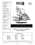
2 OPTIONAL ACCESSORIES
1
SHREDDER KIT
P/N 890209. Shreds
leaves, dramatically reducing total volume.
R
HOSE KITS
For vacuuming in hard to
reach areas.
Hea
vy Duty Vacuum
Heavy
Hose Kit P/N 900943.
4"(102mm) x 10' (3.05m)
Homeo
wner
s Vacuum
Homeowner
wners
Hose Kit P/N 900942.
4"(102mm) x 10' (3.05m)
NOZZLE WEAR PLA
TES
PLATES
P/N 900810. Extends nozzle
life when used along curbs and
hard surfaces.
ST
AND
ARD- Q
UICK
STAND
ANDARDQUICK
DEBRIS BAG P/N 890305.
Standard on KD models.
For dusty conditions.
OPTIONAL DEBRIS BAGS
TURF QUICK DEBRIS BAG
P/N 890307 for use in leaves and
grass in non-dusty conditions.
DEBRIS BAG COVER
P/N 900801 Directs dust downward away from operator.
REAR CASTER KIT
P/N 900655 Improves
maneuverability on hard
surfaces.
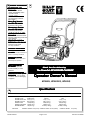
Thank You for Selecting
The P
owerful KD VACUUM CLEANER
Po
ZIPPERLESS BAG QUICK
P/N 890309 For non dusty
conditions that are damaging
to zippers.
Operator Owner's Manual
KD505H, KD505ICQ, KD505Q
Specifications
3
ENGINE: H.P.
ENGINE: TYPE
ENGINE: FUEL CAP.
ENGINE: OIL CAP.
WEIGHT: UNIT
WEIGHT: SHIPPING
ENGINE WEIGHT:
UNIT SIZE:
Part No. 890310
KD505H
KD505ICQ
KD505Q
5.5 (4.1 kW)
HONDA OHV
2.01 qt. (1.9 L)
0.69 qt.(0.65 L)
112# (50.8 kg)
135# (61.2 kg)
36# (16.3 kg)
5 (3.73 kW)
B&S I/C
1.5 qt. (1.4 L)
0.63 qt. (0.6 L)
103# (46.7 kg)
126# (57.2 kg)
24.38# (11.05 kg)
5 (3.73 kW)
B&S
1.5 qt. (1.4 L)
0.63 qt. (0.6 L)
103# (46.7 kg)
126# (57.2 kg)
24.38# (11.05 kg)
OVERALL LENGTH: 62"(1.57m) OVERALL WIDTH 26.75" (0.68m)
Page 1 of 8
OVERALL HEIGHT 42" (1.07m)
Form No. F010396B
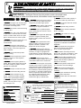
IN THE INTEREST OF SAFETY
5
BEFORE ST
AR
TING ENGINE, READ AND UNDERST
AND THE “ENTIRE OPERA
TOR'S MANU
AL & ENSTAR
ARTING
UNDERSTAND
OPERAT
MANUAL
GINE MANU
AL.
MANUAL.
AL.””
THIS SYMBOL MEANS WARNING OR CA
UTION. DEA
TH, PERSONAL INJUR
Y AND/OR PR
OPER
TY
CAUTION.
DEATH,
INJURY
PROPER
OPERTY
WED CAREFULL
Y.
DAMA
GE MA
Y OCCUR UNLESS INSTR
UCTIONS ARE FOLLO
AMAGE
MAY
INSTRUCTIONS
FOLLOWED
CAREFULLY
WARNING: The Engine Exhaust from this product contains chemicals known
to the State of California to cause cancer, birth defects or other reproductive harm.
WARNING: DO NO
T
NOT
13. DO NOT tamper with governor springs,
governor links or other parts which may
change the governed engine speed.
1. DO NOT run engine in an enclosed area.
Exhaust gases contain carbon monoxide,
an odorless and deadly poison.
14. DO NOT tamper with the engine speed
selected by the engine manufacturer.
2. DO NOT place hands or feet near moving
or rotating parts.
15. DO NOT check for spark with spark
plug or spark plug wire removed. Use an
approved tester.
3. DO NOT store, spill or use gasoline near
an open flame, or devices such as a stove,
furnace, or water heater which use a pilot
light or devices which can create a spark.
16. DO NOT crank engine with spark plug
removed. If engine is flooded, place
throttle in “FAST” position and crank until
engine starts.
4. DO NOT refuel indoors where area is not
well ventilated. Outdoor refueling is
recommended.
17. DO NO
NOT strike flywheel with a hard
object or metal tool as this may cause
flywheel to shatter in operation. Use
proper tools to service engine.
5. DO NOT fill fuel tank while engine is
running. Allow engine to cool for 2 minutes
before refueling. Store fuel in approved
safety containers.
18. DO NOT operate engine without a
muffler. Inspect periodically and replace, if
necessary. If engine is equipped with
muffler deflector, inspect periodically and
replace, if necessary, with correct deflector.
6. DO NOT remove fuel tank cap while
engine is running.
7. DO NOT operate engine when smell of
gasoline is present or other explosive
conditions exist.
19. DO NOT operate engine with an
accumulation of grass, leaves, dirt or other
combustible material in the muffler area.
8. DO NOT operate engine if gasoline is
spilled. Move machine away from the spill
and avoid creating any ignition until the
gasoline has evaporated.
20. DO NOT use this engine on any forest
covered, brush covered, or grass covered
unimproved land unless a spark arrester is
installed on the muffler. The arrester must
be maintained in effective working order by
the operator. In the State of California the
above is required by law (Section 4442 of
the California Public Resources Code).
Other states may have similar laws.
Federal laws apply on federal lands.
9. DO NOT transport unit with fuel in tank.
10. DO NOT smoke when filling fuel tank.
11. DO NOT choke carburetor to stop
engine. Whenever possible, gradually
reduce engine speed before stopping.
12. DO NOT run engine at excessive
speeds. This may result in injury
7
& /or damage to unit.
6
TABLE OF CONTENTS
SAFETY INSTRUCTIONS
GENERAL SAFETY
ASSEMBL
Y
ASSEMBLY
LIT
AG & CONTR
OLS
LIT.. B
BA
CONTROLS
LABELS
OPERA
TION
OPERATION
PAR
TS DRA
WING & LIST
ARTS
DRAWING
MAINTENANCE
TROUBLESHOOTING
WARRANTY PR
OCEDURE
PROCEDURE
○
○
○
○
○
○
○
○
○
○
○
○
○
Part No. 890310
○
○
○
○
○
L
A
96
○
LpA
109
○
OPERATOR
23. DO NOT operate during excessive
vibration!
24. DO NOT leave machine unattended
while in operation.
25. DO NOT park machine on a steep
grade or slope.
WARNING: DO
WAYS DO remove the wire from the
1. AL
ALW
spark plug when servicing the engine or
equipment TO PREVENT ACCIDENTAL
STARTING.
2. DO keep cylinder fins and governor
parts free of grass and other debris
which can affect engine speed.
3. DO pull starter cord slowly until resistance is felt. Then pull cord rapidly to avoid
kickback and prevent hand or arm injury.
4. DO examine muffler periodically to be
sure it is functioning effectively. A worn or
leaking muffler should be repaired or
replaced as necessary.
5. DO use fresh gasoline. Stale fuel can
gum carburetor and cause leakage.
6. DO check fuel lines and fittings frequently for cracks or leaks. Replace if
necessary
7. Follow engine manufacturer operating
and maintenance instructions.
8. Inspect machine and work area before
starting unit.
VIBRA
TION
VIBRATION
VIBRATION LEVELS 2.7g
Sound tests conducted were in accordance
with 79/113/EEC and were performed on
05/03/94 under the conditions listed:
GENERAL CONDITION:
22. DO NOT run engine without air cleaner
or air cleaner cover.
8
SOUND TESTS
○
○
○
○
○
○
○
○
2
3
3
4
4
5
6-7
8
8
8
○
○
○
○
○
○
○
○
○
○
○
○
SOUND
21. DO NO
NOT touch hot muffler, cylinder, or
fins because contact may cause burns.
Partly Cloudy
Vibration levels at the operators handles were
measured in the vertical, lateral, and longitudinal
directions using calibrated vibration test equipment.
Tests were performed on 05/03/94 under the conditions
listed:
Partly Cloudy
GENERAL CONDI-
TION:
TEMPERATURE:
60 F (15.5 C)
TEMPERATURE:
60 F (15.5 C)
WIND SPEED:
5 MPH (8kmh)
WIND SPEED:
5 MPH (8kmh)
WIND DIRECTION:
N.E.
WIND DIRECTION:
N.E.
HUMIDITY:
70 %
70 %
HUMIDITY:
BAROMETRIC PRESSURE:29.8" Hg (757mm Hg)
Page 2 of 8
BAROMETRIC PRESSURE:29.8" Hg (757mm Hg)
Form No. F010396B
GENERAL SAFETY
9
For your safety and the safety of others, these directions should be followed:
Do not operate this machine without first reading
owner's manual and engine manufacturer's manual.
Use of Ear Protection is recommended while
operating this machine.
Use of Eye and Breathing protection is recom-mended when using this machine, especially in dry
and dusty conditions. Optional bag cover directs dust
toward ground, away from the operator.
·DO NOT place hands or feet inside nozzle intake opening
neardebris outlet or near any moving parts.
·DO NOT start engine without debris bag and quick discon
nect connected firmly in place to exhaust outlet.
·DO NOT start or operate machine with debris bag zipper
open.
10
·DO NOT operate during excessive vibration.
·DO NOT remove bag until engine has been turned off and has
come to a complete stop.
·DO NOT remove hose kit cap on nozzle until engine has been
turned off and has come to a complete stop.
·DO NOT operate machine with hose cap, bag or hose removed.
·DO NOT use this machine for vacuuming exclusively sand,
dust, fine dirt, rock, glass, string like material, grain, rags,
cans, metal, bark or water.
·DO NOT operate this machine on slopes greater than 20%.
·DO NOT pick up any hot or burning debris, or any toxic or
explosive material.
·DO NOT allow children to operate this equipment.
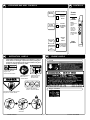
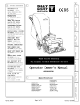
ASSEMBLY
1. ASSEMBLE Lift upper handle (item 6), remove items 8, 14, 16, & 30 from
lower handle (item 27). Attach upper and lower handle as shown,
and securely tighten folding handle knobs(item 16),while holding head of
screw(item 8) firmly against upper handle.
2. UNFOLD the debris bag (item 1) and fasten bag neck to bag quick
disconnect (item 12). Attach firmly to housing exhaust (item 52) see fig. 2.
3. ATTACH bag hanger strap to bag supports (item 11), preassembled to
upper handle.
4. CONNECT spark plug wire.
Read all safety and operating instructions
before assembling or starting this unit.
PUT OIL IN ENGINE BEFORE STARTING
Your Billy Goat is shipped from the factory in one carton,
completely assembled except for the upper handle, debris bag,
and bag quick disconnect.
11
PACKING CHECKLIST
These items should be included in your carton. If
any of these parts are missing, contact your dealer.
Check
Check
6
QUICK DISCONNECT
Check
8
Literature
Bag
Assembly
16 30
14
Debris Bag
890304
Connector
Quick
Disconnect
890176
Per Model
Literature Bag
Assembly
890319
Per Model
Check
27
Engine
Manual
Per Model
{
Briggs & Stratton
P/N MS9984 Multi-Lang.
Check
Honda
P/N 31ZE6030 00X31ZE6-0300 English
Fig. 2
Part No. 890310
Page 3 of 8
Form No. F010396B
12
LITERATURE BAG ASSY P/N 890319
13
Owner's
Manual
Literature Checklist
Check
Owner's
Manual
890310
Literature
KD / TKD
Accessories
Check
Literature
KD / TKD505
Accessories
890317
Check
Warranty
Card
400972
Warranty
Card
Throttle
Control
Stop
position
Briggs
engines have
a primer
button
carburetor
rather than
choke type
carburetor.
Honda - Place
in fast position
to start.
STOP
SLOW
FAST
Start
position
4
Check
EU Declaration
of Conformity &
EU Distributor
List 890260
CONTROLS
EU Declaration
of Conformity
& EU
Distributor List
14
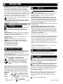
INSTRUCTION LABELS
15
These labels should be included on your Vacuum. If any of
these labels are damaged, replace them before putting this
equipment into operation. Item and part numbers are given
to help in ordering replacement labels.
WARNING
Honda
DANGER
400268
EXPLOSIVE FUEL
ENGINE LABELS
STOP ENGINE AND ALLOW TO
COOL BEFORE REFUELING.
810736
Label Do Not Fill While
Engine Is Hot
Item 63 Part No.400268
Label Read Owner's
Manual Item 71
Part No.890301
DANGER
Label Danger Flying
Material Item 62
Part No.810736
890254
KEEP HANDS and FEET AWAY
Label Ear Eye Breathing
Item No. 13 Part No. 890254
Briggs & Stratton
Label Danger Keep Hands and Feet
Away Item 70 Part No.400424
Debris Bag
Label item 1
Part No. 890310
Page 4 of 8
Form No. F010396B
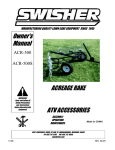
OPERATION
16
INTENDED USE: This machine is designed for vacuuming leaves,
grass clippings and other types of organic litter. Debris mixed with
16.3
DEBRIS BAG
cans, bottles and small amounts of sand can be vacuumed;
however, it is not this machine's primary purpose. Vacuuming
Debris bags are normal replaceable wear items.
cans, bottles and sand will affect the longevity of your machine.
Note: Frequently empty debris to prevent bag overloading with
Do not operate if excessive vibration occurs. If excessive vibration
more weight than you can lift.
occurs, shut engine off immediately and check for damaged or worn
impeller, loose impeller bolt, loose impeller key, loose engine or lodged An optional bag and dust cover is available for use where debris will
be vacuumed in dusty conditions (see Optional Accessories
foreign objects. Note: See parts list for proper impeller bolt torque
shown on page 1).
specifications. (See trouble shooting section on page 8).
Like all mechanical tools, reasonable care must be used
when operating machine.
Inspect machine work area and machine before operating.
Make sure that all operators of this equipment are trained in
general machine use and safety.
PUT OIL IN ENGINE BEFORE STARTING
STARTING
16.1
ENGINE: See engine manufacturer’s instructions
for type and amount of oil and gasoline used.
Engine must be level when checking and filling oil and
gasoline.
ENGINE SPEED: Controlled by throttle lever on the handle.
Under normal conditions, operate at minimum throttle to
accomplish your current cleaning task.
FUEL VALVE: Move fuel valve to "ON" position (when
provided on engine).
CHOKE: Operated with throttle control (Honda only).
PRIMER: Push primer on Briggs & Stratton Engines.
THROTTLE: Move remote throttle control to fast position.
Pull starting rope to start engine.
IF YOUR UNIT FAILS TO START:
See Troubleshooting on page 8.
16.2
VACUUM NOZZLE HEIGHT ADJUSTMENT: is raised
and lowered by pushing slightly downward on handle and
pulling ht. adj. rod(Item 23) at left side of handle.
FOR MAXIMUM PICKUP: Adjust nozzle close to debris, but
without blocking airflow into the nozzle. NOTE: Never bury nozzle
into debris.
CLEARING A CLOGGED NOZZLE
& EXHAUST: Turn engine off and wait for impeller to
stop completely and disconnect spark plug wire.
Wearing durable gloves, remove clog. Danger, the
clog may contain sharp materials. Reconnect spark
plug wire.
Nozzle Height Fine Adjustment For Hard Surface
Use: Optimum nozzle height is 1/2" (12.7mm) above ground
with engine not running. To adjust height, loosen screws (item 37),
on quad plate. Prop front of nozzle up 1.0" (25.4mm) above
ground. Keeping wheels on ground, re-tighten screws (item 37).
Recheck and fine adjust to obtain 1/2" (12.7mm) at nozzle front
(see fig 1).
Adjustment
Item 37 Ref. Securely
Lowers
Tighten, position slots
Nozzle
toward unit. Can be
(fig. 1)
Part No. 890310
•The debris bag must be cleaned more frequently.
A vacuum
with a clean, pillow soft bag will have good pickup performance.
One with a dirty, tight bag will have poor pickup performance.
If dirty, empty debris and vigorously shake bag free-of-dust.
•Machine or pressure-wash debris bag if normal cleaning
does not fully clean bag. Bag should be thoroughly dry before
use.
Having one or more spare debris bags is a good way to reduce down
time while dirty bags are being cleaned.
•DO NOT
VACUUMING OPERATION
Rod In
First Hole
DO NOT place bag on or near hot surface, such as engine.
Run engine at 1/2 throttle for first 1/2 hour to condition new
bag. Your new bag requires a break-in period to condition the
pores of the material against premature blockage. The entire
bag surface serves as a filter, and must be able to breath to
have good vacuum performance.
Be sure engine has come to a complete stop before removing
or emptying bag.
This vacuum is designed for picking up trash, organic
material and other similar debris (see Safety Warnings page 2 & 3).
However, many vacuums are used where dust is mixed with
trash. Your unit can intermittently vacuum in dusty areas. Dust
is the greatest cause of lost vacuum performance. However,
following these rules will help maintain your machine's ability
to vacuum in dusty conditions:
•Run machine at idle to quarter throttle.
reversed to provide better
hole alignment if required.
16.4
leave debris in bag while in storage.
HANDLING & TRANSPORTING:
Using two people to lift machine is recommended. Lift holding the
handle and front of nozzle. Secure in place during transport.
16.5
STORAGE
Never store engine indoors or in enclosed poorly ventilated
areas with fuel in tank, where fuel fumes may reach an open
flame, spark or pilot light, as on a furnace, water heater, clothes
dryer or other gas appliance.
If engine is to be unused for 30 days or more, prepare as follows:
Be sure engine is cool. Do not smoke. Remove all
gasoline from carburetor and fuel tank to prevent gum deposits
from forming on these parts and causing possible malfunction of
engine. Drain fuel outdoors, into an approved container, away
from open flame. Run engine until fuel tank is empty and
engine runs out of gasoline.
NOTE: Fuel stabilizer (such as Sta-Bil) is an acceptable alternative in minimizing
the formation of fuel gum deposits during storage. Add stabilizer to gasoline in
fuel tank or storage container. Always follow mix ratio found on stabilizer
container. Run engine at least 10 min. after adding stabilizer to allow it to reach
the carburetor.
Do not store with debris in bag.
Adjustment
Raises Nozzle
Page 5 of 8
Form No. F010396B
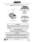
18
PARTS DRAWING
R
KD505H, KD505ICQ,
KD505Q
Part No. 890310
Page 6 of 8
Form No. F010396B
Item
No.
1
2
3
4
5
6
7
8
9
10
11
12
13
14
15
16
17
18
19
20
21
22
23
24
25
26
27
28
29
30
31
32
33
34
35
36
37
38
39
40
41
42
43
44
45
46
47
48
49
50
51
52
53
PARTS
LIST
QTY
AXLE REAR - PUSH
SCREW CURVED HEAD 5/16-18 X 2 -1/4
CLAMP CABLE 1”
SCREW, CAP 1/4 - 20 NC X 1 - 3/4 HEX
BAR SUPPORT BAG
CONNECTOR QUICK DISCONNECT
LABEL EAR EYE BREATHING
NUT LOCK 5/16-18 THIN HT.
890305
810135
*8172020
*8160001
*8041008
900054
900925
900547
900813
*8041009
900039
890176
890254
*8161041
1
1
6
5
4
1
1
2
2
1
2
1
1
2
890305
810135
*8172020
*8160001
*8041008
900054
900925
900547
900813
*8041009
900039
890176
890254
*8161041
1
1
6
5
4
1
1
2
2
1
2
1
1
2
890305
810135
*8172020
*8160001
*8041008
900054
900925
900547
900813
*8041009
900039
890176
890254
*8161041
1
1
6
5
4
1
1
2
2
1
2
1
1
2
KNOB WING 5/16-18
WASHER LOCK EXT. 5/16
BRACKET - HT. ADJ.
SCREW, CAP 5/16 NFX 1”
SPRING
TIRE - ONLY (PER ASSY)
PIN - HAIR COTTER
ROD SHORT HT. ADJ.
BOLT - CARRIAGE, 5/16 - 18 NC X 3 - 1/2 LG
WASHER - FLAT 5/16 SAE
NUT LOCK 5/16 - 18 NC HEX
HANDLE LOWER KD505
PLATE - HANDLE SUPPORT
GRIP HANDLE
WASHER FLAT CUT 5/16
SCREW CAP 5/16-18 X 2 - 1/2 LG.
WASHER HUB CAP 1/2 I.D.
AXLE FRONT MECH. ASSY. ( INCL. 17, 37, 38, 45 )
WHEEL ASS’Y (INCLUDE 21)
WASHER 0.75 “C”
890108
*8181008
900932
400164
900136
900507
900471
890110
*8024050
*8172008
*8160002
900041
900933
400570
*8171003
900927
900749
900509
900997
2
5
1
3
1
1
1
1
4
20
10
1
1
2
2
4
1
4
0-1
890108
*8181008
900932
900136
900507
900471
890110
*8024050
*8172008
*8160002
900041
900933
400570
*8171003
*8041034
900927
900749
900509
900997
2
2
1
1
1
1
1
4
20
10
1
1
2
2
1
4
1
4
0-1
890108
*8181008
900932
900136
900507
900471
890110
*8024050
*8172008
*8160002
900041
900933
400570
*8171003
*8041034
900927
900749
900509
900997
2
2
1
1
1
1
1
4
20
10
1
1
2
2
1
4
1
4
0-1
SCREW CAP 5/16-18 X 1”
SPACER 0.340” I. D. X 0.330” LG.
PLATE - BRACE REAR
SCREW CAP 1/4-20 X 1/2
SPACER
SCREW, SELF TAPPING 10 - 24 NC X 1/2 LG.
*8041028
900745
900905
*8041002
900926
*8123086
900931
900146
900746
900003 - S
890326
900162
400502
900154
900757
900615
-
2
2
2
4
6
1
1
1
1
1
1
2
1
1
1
1
-
*8041028
900745
900905
*8041002
900926
*8123086
900931
900146
900746
800411
900215 -S
890326
900162
400502
900154
900757
900273
-
2
2
2
4
6
1
1
1
1
1
1
1
1
1
1
1
1
-
*8041028
900745
900905
*8041002
900926
*8123086
900931
900146
900746
800411
900215 - S
890236
900162
400502
900154
900757
900622
2
2
2
4
6
1
1
1
1
1
1
1
1
1
1
1
1
NUT LOCK 5/16 - 18 HEX
ROD - BUMPER
SCREW CAP 5/16 - 18 x 1 - 1/4 LONG
SCREW CAP 5/16 - 18 x 1 - 1/2 LG.
CAP - HUB
WASHER - FLAT 1/2 “SAE”
PLATE BRACE HT. ADJ. KD / TKD
*8160002
900939
*8041030
900486
*8172011
900756
1
1
1
4
8
1
*8160002
900939
*8041029
900486
8172011
900756
3
1
2
8
8
1
*8160002
900939
*8041029
900486
*8172011
900756
3
1
2
8
8
1
PIN - COTTER 3/32 X 3/4
LABEL DANGER FLYING MATERIAL
LABEL DO NOT FILL WHEN ENGINE IS HOT
GUARD FOAM INSERT
DOOR EXHAUST ASSY (incl. items 62)
*8197016
810736
400268
900977
890148
4
1
1
1
1
*8197016
810736
400268
900977
890148
4
1
1
1
1
*8197016
810736
400268
900977
890148
4
1
1
1
1
SCREW CAP # 10-24
NUT LOCK # 10-24
WASHER # 10-24
LABEL DANGER KEEP HANDS and FEET
LABEL READ OWNER'S MANUAL
*8059135
*8164005
*8171001
400424
890301
2
2
2
2
1
*8059135
*8164005
*8171001
400424
890301
2
2
2
2
1
*8059135
*8164005
*8171001
400424
890301
2
2
2
2
1
Description
DEBRIS BAG Service Assembly
THROTTLE ASSEMBLY (INCL. 1 EACH ITEMS 4, 10)
WASHER - FLAT FENDER (11/32 X 1 - 1/4 X 0.05)
NUT LOCK (1/4 - 20 NC)
SCREW, CAP ( 1/4 - 20 NC X 1 -1/2 HEX)
HANDLE ASSY (INCL. ITEMS 4(4), 5(4), 11(2), 29(2) )
NOZZLE MAIN FRAM. ASS’Y - GREEN (INCL. item (qty) 44 (1), 42 ( 1) , 55( 1), 64(1), 70(1))
PLUG
PLATE QUAD ADJUSTABLE
GASKET
IMPELLER ASS’Y’ (INCLUDES iTEM 49, 50, 51)
HEIGHT ADJUST ASSY
KEY HI PRO 5/32 X 5/8
WASHER LOCK 3/8 TWISTED TOOTH
SCREW CAP 3/8-24 x 1" TORQUE 50 FT- LBS (68 N.m)
HOUSING ASS’Y (INCL. 1 EA . ITEMS 13, 65, 67, 68, 69, 70)
ENGINE 5.5 HP HONDA
ENGINE 5 HP
ENGINE 5 HP
54
55
56
57
58
59
60
61
62
63
64
65
66
67
68
69
70
71
KD505ICQ
Part No.
KD505H
Part No.
19
BRIGGS & STRATTON "IC" QUANTUM
BRIGGS & STRATTON QUANTUM
QTY
KD505Q
Part No.
QTY
* Denotes standard hardware that may be purchased locally.
Part No. 890310
Page 7 of 8
Form No. F010396B
MAINTENANCE
17
IMPELLER REMOVAL continued
Use only a qualified mechanic for
any adjustments, disassembly or
any kind of repair .
5.Disassemble housing by removing six (6) lock nuts and washers from nozzle frame, (2
are inside of nozzle opening).
6.Remove impeller bolt and lock washer.
7.Lift impeller upward. If impeller slides freely, proceed to (step 10).
8 .Place two crowbars between impeller and housing on opposite sides. Pry impeller away
from engine until it loosens. Using a penetrating oil can help loosen a stuck impeller.
WARNING: TO AVOID PERSONAL INJURY, ALWAYS
TURN MACHINE OFF, MAKE SURE ALL MOVING
PARTS COME TO A COMPLETE STOP.
9.If the impeller does not loosen, obtain a 1” (25.4mm) longer bolt of the same diameter
and thread type as the impeller bolt. Thread longer bolt by hand into the crankshaft until
bolt bottoms. Using a suitable gear or wheel puller against the bolt head and the impeller
back-plate (near the blades), remove impeller from shaft.
10.Remove engine mounting screws, bolts, and nuts as required.
11.When impeller is free of the engine shaft, lift impeller and housing assembly off engine.
Align impeller with opening, and diagonally lift impeller out of housing.
12. Using a new impeller bolt and lockwasher, reinstall new impeller in reverse order.
13. Tighten impeller bolt. Torque impeller bolt to 50 Ft. Lbs.(68 N.m) (see item 51 on page 7).
14. Reinstall engine onto housing in reverse order of removal.
15. Invert machine back onto all 4 wheels.
16. Reinstall spark plug wire.
DISCONNECT SPARK PLUG WIRE
BEFORE SERVICING UNIT.
ENGINE: See engine manufacturer
operator's instructions.
DEBRIS BAG: See page 5.
RECONNECT SPARK PLUG WIRE,
GUARDS, BAG, CAPS AND / OR
HOSE BEFORE STARTING ENGINE.
17.2
Maintenance Schedule
Maintenance Operation
Follow these hourly maintenance intervals.
Every
Use
Every 5 hrs
or (Daily)
Engine (See Engine Manual)
17.1
Check for excessive vibration
IMPELLER REMOVAL
Clean Debris Bag
1.Wait for engine to cool and disconnect spark plug.
2 .Drain fuel and oil from the engine.
3.Remove bag, quick release, and upper handle. Do not kink, stretch, or break
control cables, control housings, or end fittings while removing handles.
4.Invert and support machine with engine not touching ground to prevent damage
to recoil starter.
20
TR
OUBLESHOO
TING
TROUBLESHOO
OUBLESHOOTING
Problem
Check bag strap tightness
Inspect for loose parts
Inspect for worn or damaged parts
Before Requesting Service Review These Suggestions
Possible Cause
Solution
Will not vacuum or has poor
vacuum performance.
Dirty debris bag. Nozzle height set too high or too low. Hose kit cap
missing. Clogged nozzle or exhaust. Excessive quantity of debris.
Clean debris bag. Shake bag clean or wash. Adjust nozzle height.
Check for hose kit cap. Unclog nozzle or exhaust (see page 5).
Allow air to feed with debris.
Abnormal vibration.
Loose or out of balance impeller or loose engine.
Check impeller and replace if required. Check Engine.
Engine will not start.
Stop switch off (Honda only). Throttle in off position. Engine not in
full choke position (Honda only). Out of gasoline. Bad or old
gasoline. Spark Plug wire disconnected. Dirty air cleaner.
Check stop switches, throttle, choke position and gasoline. Connect
spark plug wire. Clean or replace air cleaner. Or contact a qualified
service person.
Engine is locked, will not
pull over.
Debris locked in impeller. Engine problem.
See page 5, Contact an engine servicing dealer for engine problems.
Nozzle scrapes ground in
lowest height setting.
Nozzle height out of adjustment.
Adjust nozzle height. (See Nozzle height fine adjustment for hard
surface use on page 5).
22.1
21
Engine Service and Warranty
Contact your nearest engine manufacturer's authorized servicing dealer.
Record your machine model, serial number
and date-of-purchase and where purchased
Serial Plate
L
A
96
LpA
Model
The Machine should be taken to the dealer from whom it was
purchased or to an authorized Billy Goat dealer.
The owner should present the remaining half of the Warranty
Registration Card, or, if this is not available, the invoice or receipt.
The Warranty Claim will be filled in by the authorized Billy Goat Dealer,
who will send it with the faulty part to Billy Goat headquarters.
Serial No.
Unit(Weight)
lbs.
The Quality / Service department at Billy Goat headquarters will study
the claim and parts and will notify their conclusions.
The decision by the Quality / Service department at Billy Goat
headquarters to approve or reject a Warranty claim is final and
binding.
Engine Power
kg
kW
rpm
min -1
Operator
Purchase
Date
WARRANTY PROCEDURE
Please fill in the WARRANTY CARD and send the upper part to Billy Goat.
The WARRANTY terms are stated on the lower part which remains with the
user. Whenever a Billy Goat Machine is faulty due to a defect in material
and / or workmanship, the owner should make a warranty claim as follows:
1803 S. Jefferson
P.O. Box 308
Lee's Summit,
MO 64063 / USA
Tel (816) 524-9666
Fax (816) 524-6983
R
109
22
Note: To process a Warranty Claim, it is necessary to quote the Model
& Serial number who are printed on the Billy Goat Serial Plate.
Purchased
from
Part No. 890310
R
Page 8 of 8
BILLY GOAT INDUSTRIES INC.
P.O. BOX 308 1803 S JEFFERSON LEE'S SUMMIT, MO 64063 / USA
PHONE: 816-524-9666 FAX: 816-524-6983
Form No. F010396B