1
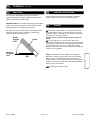
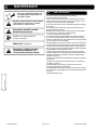
2
OPTIONAL ACCESSORIES
1
SHREDDER KIT
95
R
P/N 890209. Shreds
leaves, dramatically reducing total volume.
HOSE KITS
GENERAL SAFETY
3
&
ASSEMBLY
For vacuuming in hard to
reach areas.
SAFETY
2
INSTRUCTIONS
4
Hea
vy Duty Vacuum
Heavy
Hose Kit P/N 900943.
4"(102mm) x 10' (3.05m)
Homeo
wner
s Vacuum
Homeowner
wners
Hose Kit P/N 900942.
4"(102mm) x 10' (3.05m)
NOZZLE WEAR PLA
TES
PLATES
PA RTS BAG & CON4
TROLS & LABELS
P/N 900810. Extends nozzle
life when used along curbs and
hard surfaces.
ST
AND
ARD FEL
T
STA
DARD
FELT
DEBRIS BAG P/N
900803. Standard on KD
models. For dusty conditions.
OPTIONAL DEBRIS BAGS
5-7
TURF DEBRIS BAG
P/N 900806 For use in leaves
and grass in non-dusty conditions.
panel.
DEBRIS BAG COVER
P/N 900801 Directs dust
Thank You for Selecting
BAG SUPPORT KIT
The P
owerful K D SELF-PR
OPELLED VA C U U M
Po
SELF-PROPELLED
P/N 900645 Extends bag life by
keeping bag from dragging ground.
ZIPPERLESS BAG
Operator Owner's Manual
conditions that are damaging
to zippers.
KD502SPQ
PA RTS DRAW I N G
& LIST
10 - 12
P/N 890221 For non dusty
SL O
W DO W
N KIT
OW
WN
P/N 890216
Reduces ground speed for
KDSP vacuums.
Now standard on KDSP.
3
Specifications
KD502SPQ
UNIT SIZE:
Part No. 890257
OVERALL LENGTH: 62"(1.57m)
5 (3.73 kW)
B&S QUANTUM
1.5 qt. (1.4 L)
0.63 qt. (0.6 L)
117# (53.1 kg)
140# (63.5 kg)
25.25# (11.45 kg)
12
ENGINE: H.P.
ENGINE: TYPE
ENGINE: FUEL CAP.
ENGINE: OIL CAP.
WEIGHT: UNIT
WEIGHT: SHIPPING
ENGINE WEIGHT:
OVERALL WIDTH 26.75" (0.68m) OVERALL HEIGHT42" (1.07m)
Page 1 of 12
Form No. F021695H
TROUBLE SHOOTING,
& W ARRANTY PROCEDURE
dow n ward, aw ay from operator.
MAINTENANCE
P/N 900798 R einforced lower
8 - 9
O P E R ATION
HEA
VY DUTY DEBRIS BA
G
AVY
BAG
IN THE INTEREST OF SAFETY
5
2
BEFORE ST
AR
TING ENGINE, READ AND UNDERST
AND THE “ENTIRE OPERA
TOR'S MANU
AL & ENSTA
RTING
UNDERSTAND
OPERAT
MANUAL
AL.
”
MANUAL.
AL.”
GINE MANU
SAFETY
THIS SYMBOL MEANS W ARNING OR CA
UTION. DEA
TH, PERSONAL INJUR
Y AND/OR PR
OPER
TY
CAUTION.
DEATH,
INJURY
PRO
RTY
Y.
GE MA
Y OCCUR UNLESS INSTR
UCTIONS ARE FOLLO
WED CAREFULL
AGE
MAY
INSTRUCTIONS
FOLLOWED
CAREFULLY
DA M A
W ARNING: DO
13. DO NOT tamper with governor springs,
governor links or other parts which may
change the governed engine speed.
NO
T
NOT
1. DO NOT run engine in an enclosed area.
Exhaust gases contain carbon monoxide,
an odorless and deadly poison.
14. DO NOT tamper with the engine speed
selected by the engine manufacturer.
2. DO NOT place hands or feet near moving
or rotating parts.
15. DO NOT check for spark with spark
plug or spark plug wire removed. Use an
approved tester.
3. DO NOT store, spill or use gasoline near
an open flame, or devices such as a stove,
furnace, or water heater which use a pilot
light or devices which can create a spark.
16. DO NOT crank engine with spark plug
removed. If engine is flooded, place
throttle in “FAST” position and crank until
engine starts.
4. DO NOT refuel indoors where area is not
well ventilated. Outdoor refueling is
recommended.
17. DO NO
NOT strike flywheel with a hard
object or metal tool as this may cause
flywheel to shatter in operation. Use
proper tools to service engine.
5. DO NOT fill fuel tank while engine is
running. Allow engine to cool for 2 minutes
before refueling. Store fuel in approved
safety containers.
6. DO NOT remove fuel tank cap while
engine is running.
18. DO NOT operate engine without a
m uffler. Inspect periodically and replace,if
necessary. If engine is equipped with
m uffler deflector, inspect periodically and
replace, if necessary, with correct deflector.
7. DO NOT operate engine when smell of
gasoline is present or other explosive
conditions exist.
19. DO NOT operate engine with an
accumulation of grass, leaves, dirt or other
combustible material in the muffler area.
8. DO NOT operate engine if gasoline is
spilled. Move machine away from the spill
and avoid creating any ignition until the
gasoline has evaporated.
20. DO NOT use this engine on any forest
covered, brush covered, or grass covered
unimproved land unless a spark arrester is
installed on the muffler.The arrester must
be maintained in effective working order by
the operator. In the State of California the
above is required by law (Section 4442 of
the California Public Resources Code).
Other states may have similar laws.
Federal laws apply on federal lands.
9. DO NOT transport unit with fuel in tank.
10. DO NOT smoke when filling fuel tank.
11. DO NOT choke carburetor to stop
engine. Whenever possible, gradually
reduce engine speed before stopping.
12. DO NOT run engine at excessive
speeds. This may result in injury & /or
damage to unit.
TABLE OF CONTENTS
2
SAFETY INSTRUCTIONS
3
GENERAL SAFETY
ASSEMBL
Y
LY
3
4
PA R
TS B
A G & CONTR
OLS
RTS
BA
CONTRO
4
LABELS
5-7
OPERA
TION
ATION
8-9
MAINTENANCE
10 - 12
PA R
TS DRA
WING & LIST
RTS
DRAWING
12
TROUBLESHOOTING
12
W ARRANTY PR
OCEDURE
PRO
○
○
○
○
○
○
○
○
○
○
○
○
○
○
○
○
○
○
○
○
○
○
○
○
○
○
Part No. 890257
○
○
○
○
○
○
○
○
○
○
○
23. DO NOT operate during excessive
vibration!
24. DO NOT leave machine unattended
while in operation.
25. DO NOT park machine on a steep
grade or slope.
W ARNING: DO
W AYS DO remove the wire from the
1. A L
LW
spark plug when servicing the engine or
equipment TO PREVENT ACCIDENTAL
STA RTING.
2. D O keep cylinder fins and governor
parts free of grass and other debris
which can affect engine speed.
3. D O pull starter cord slowly until resistance is felt. Then pull cord rapidly to avoid
kickback and prevent hand or arm injury.
4. D O examine muffler periodically to be
sure it is functioning effectively. A worn or
leaking muffler should be repaired or
replaced as necessary.
5. D O use fresh gasoline. Stale fuel can
gum carburetor and cause leakage.
6. D O check fuel lines and fittings frequently for cracks or leaks. Replace if
necessary
7. Follow engine manufacturer operating
and maintenance instructions.
8. Inspect machine and work area before
starting unit.
A
96
VIBRATION LEVEL
LpA
109
Sound tests conducted were in accordance
with 79/113/EEC and were performed on 05/
20/94 under the conditions listed:
GENERAL CONDITION:
VIBRA
TION
VIBRATION
8
SOUND TESTS
○
○
22. DO NOT run engine without air cleaner
or air cleaner cover.
SOUND
7
L
6
21. DO NO
NOT touch hot muffler, cylinder,or
fins because contact may cause burns.
Sunny
2.7g
Vibration levels at the operators handles were
measured in the vertical, lateral, and longitudinal
directions using calibrated vibration test equipment.
Tests were performed on 05/20/94 under the conditions
listed:
Sunny
GENERAL CONDI-
TION:
T E M P E R ATURE:
70 F (21.1 C)
T E M P E R ATURE:
70 F (21.1 C)
WIND SPEED:
3 MPH (4.8 kmh)
WIND SPEED:
3 MPH (4.8 kmh)
WIND DIRECTION:
N.W.
WIND DIRECTION:
N.W.
HUMIDITY:
58 %
HUMIDITY:
58 %
○
OPERATO R
BAROMETRIC PRESSURE:30.1" Hg (765mm Hg)
Page 2 of 12
BAROMETRIC PRESSURE:30.1" Hg (765mm Hg)
Form No. F021695H
9
GENERAL SAFETY
Do not operate this machine without first reading
owner's manual and engine manufacturer's manual.
Use of Ear Protection is recommended while
operating this machine.
Use of Eye and Breathing protection is recommended when using this machine, especially in dry
and dusty conditions. Optional bag cover directs dust
toward ground, away from the operator.
·DO NOT place hands or feet inside nozzle intake opening,
near debris outlet or near any moving parts.
·DO NOT start engine without debris bag and quick disconnect connected firmly in place to exhaust outlet.
·DO NOT start or operate machine with debris bag zipper
open.
10
ASSEMBLY
Read all safety and operating instructions
before assembling or starting this unit.
PUT OIL IN ENGINE BEFORE STARTING.
Your Billy Goat is shipped from the factory in one carton,
completely assembled except for the debris bag, upper handle,
height adjustment rod and bag quick disconnect.
11
·DO NOT operate during excessive vibration.
·DO NOT remove bag until engine has been turned off and has
come to a complete stop.
·DO NOT remove hose kit cap on nozzle until engine has been
turned off and has come to a complete stop.
·DO NOT operate machine with hose cap, bag or hose removed.
·DO NOT use this machine for vacuuming exclusively sand,
dust, fine dirt, rock, glass, string like material, grain, rags,
cans, metal, bark or water.
·DO NOT operate this machine on slopes greater than 20%.
·DO NOT pick up any hot or burning debris, or any toxic or
explosive material.
·DO NOT allow children to operate this equipment.
1. ASSEMBLE upper handle securely to lower handle stubs using handle
screws (item 8), washers (item 25) and nut lock 5/16-18 (item 26), with
screw heads facing inward toward debris bag. Otherwise, premature bag
wear could result.
2. ASSEMBLE height adjustment rod (item 23), thru eye bolt (item 15), on
upper handle and thru upper flange of height adjustment bracket (item18),
thru spring (item 20), and thru lower flange of height adjustment bracket
(item 18). Insert pin (item 22), between spring and lower flange of height
adjustment bracket (see VIEW A on page 10). Slide grip (item 46), onto
upper end of height adjustment rod (item 23).
3. UNFOLD the debris bag (item 1) and fasten bag neck to bag quick
disconnect (item 12). Attach firmly to housing exhaust (item 52) see fig. 2.
4. ATTACH bag hanger straps to loops (item 11), preassembled to upper
handle.
5. ATTACH throttle assy. (item 2), to handle using cable clamps (item 9).
6. CONNECT spark plug wire.
PACKING CHECKLIST
These items should be included in your carton. If
any of these parts are missing, contact your dealer.
Check
Debris Bag
900802
Check
Check
46
Connector
Quick
Disconnect
890176
Handle Assy
900967
Check
Rod Height
Adj. 900978
23
8
Per Model
9
Check
Quick Disconnect
26
25
20
Attach upper handle
using screws, washers
and lock nuts provided
in parts bag.
Fig. 2
Part No. 890257
22
Parts Bag
& Literature Assy
Parts Bag &
Literature Assy
900968
Check
Engine
Manual
Briggs & Stratton
P/N 272262 English
Denotes parts found in Parts Bag Assembly (shown on page 4).
Page 3 of 12
Form No. F021695H
GENERAL SAFETY
3
&
ASSEMBLY
For your safety and the safety of others, these directions should be followed:
12
PARTS BAG & LITERATURE ASSY P/N 900968
PARTS BAG ASSEMBLY CHECKLIST
13 CONTROLS
P/N 900974
Owner's
Manual
Literature Checklist
Check
Literature
Parts Bag
25 Washer
5/16 SAE
8172008
Qty. 2
Literature
KD / TKD
Accessories
Owner's
Manual
890257
Check
Check
Check
Warranty
Card
9
Clamp Cable 1"
900813 Qty. 2
Check
EU Declaration
of Conformity
& EU
Distributor List
22 PinHair Cotter
900471 Qty. 1
8
Screw Cap
5/16-18 x 1 1/2
8041030 Qty. 2
14
890258
Literature
KD / TKD
Accessories
900713
Briggs
engines have
a primer
button
carburetor
rather than
choke type
carburetor.
C
H
O
K
E
FAST
Warranty
Card
400972
EU Declaration
of Conformity &
EU Distributor
List 890266
46 Grip
900937 Qty. 1
INSTRUCTION LABELS
SLOW
STOP
Stop
position
ENGINE LABELS
15
These labels should be included on your Vacuum. If any of
these labels are damaged, replace them before putting this
equipment into operation. Item and part numbers are given to
help in ordering replacement labels..
Label Danger
Keep Hands
and Feet
Away
Item 29 Part
No.400424
STOP ENGINE AND ALLOW TO
COOL BEFORE REFUELING.
Label Do Not Fill While
Engine Is Hot
Item 63 Part No.400268
DANGER
KEEP HANDS and FEET AWAY
Briggs & Stratton
DANGER
810736
900327
WARNING
Label Danger Flying
Material Item 62
Part No.810736
Label Warning Guards
Item 100 Part No.900327
900328
Label Read Owner's
Manual Item No. 123
Part No. 890301
PULL TO ENGAGE CLUTCH
RELEASE TO DISENGAGE CLUTCH
Label Ear Eye Breathing
Item No. 37 Part No. 890254
Label Clutch Item No. 99
Part No. 900328
830502
400268
WARNING
EXPLOSIVE FUEL
890254
PA RTS BAG & CON4
TROLS & LABELS
26 Nut Lock
5/16-18
8160002
Qty. 2
Start
position
Literature
Parts Bag
20
Spring
900136 Qty. 1
Throttle
Control
OIL CHAIN
EVERY 10 HOURS
Label Oil Chain
Item No. 45
Part No. 830502
Debris Bag
Label item 1
Part No. 890257
Page 4 of 12
Form No. F021695H
OPERATION
16
INTENDED USE: This machine is designed for vacuuming
leaves, grass clippings and other types of organic litter.
Debris mixed with cans, bottles and small amounts of sand
can be vacuumed; however, it is not this machine's primary
purpose. Vacuuming cans, bottles and sand will affect the
longevity of your machine.
Do not operate if excessive vibration occurs. If excessive
vibration occurs, shut engine off immediately and check for
damaged or worn impeller, loose impeller bolt, loose impeller
key, loose engine or lodged foreign objects. Note: See parts
list for proper impeller bolt torque specifications. (See trouble
shooting section on page 12).
Like all mechanical tools, reasonable care must
be used when operating machine.
Inspect machine work area and machine before operating. Make sure that all operators of this equipment are
trained in general machine use and safety.
PUT OIL IN ENGINE BEFORE STARTING.
16.1
STARTING
O P E R ATION
5
ENGINE: See engine manufacturer’s instructions
for type and amount of oil and gasoline used.
Engine must be level when checking and filling oil and
gasoline.
ENGINE SPEED: Controlled by throttle lever on the handle.
Under normal conditions, operate at minimum throttle to
accomplish your current cleaning task.
FUEL VALVE: Move fuel valve to "ON" position (when
provided on engine).
CHOKE: See Primer.
PRIMER: Push primer per engine instructions.
THROTTLE: Move remote throttle control to fast position.
Pull starting rope to start engine.
IF YOUR UNIT FAILS TO START:
See Troubleshooting on page 12.
16.2
VACUUMING OPERATION
VACUUM NOZZLE HEIGHT ADJUSTMENT: is
raised and lowered by lifting slightly upward on handle and
up on height adjustment rod located at left side of handle.
The nozzle height can be adjusted during operation without
stopping.
FOR MAXIMUM PICKUP: Adjust nozzle close to debris,
but without blocking airflow into the nozzle. NOTE: Never bury
nozzle into debris.
CLEARING A CLOGGED NOZZLE
& EXHAUST: Turn engine off and wait for impeller to
stop completely and disconnect spark plug wire.
Wearing durable gloves, remove clog. Danger, the
clog may contain sharp materials. Reconnect spark
plug wire.
Part No. 890257
Page 5 of 12
Form No. F021695H
16
OPERATION
16.3
DEBRIS BAG
continued
Debris bags are normal replaceable wear items.
Note: Frequently empty debris to prevent bag overloading with
more weight than you can lift.
An optional bag and dust cover is available for use where debris will
be vacuumed in dusty conditions (see Optional Accessories shown
on page 1.)
DO NOT place bag on or near hot surface, such as engine. Run
engine at 1/2 throttle for first 1/2 hour to condition new bag.Your new
bag requires a break-in period to condition the pores of the material
against premature blockage.The entire bag surface serves as a filter,
and must be able to breath to have good vacuum performance.
Be sure engine has come to a complete stop before removing
or emptying bag.
This vacuum is designed for picking up trash, organic
material and other similar debris (see Safety Warnings page 2-3).
However, many vacuums are used where dust is mixed with
trash. Your unit can intermittently vacuum in dusty areas. Dust
is the greatest cause of lost vacuum performance. However,
following these rules will help maintain your machine's ability
to vacuum in dusty conditions:
•Run machine at idle to quarter throttle.
O P E R ATION
6
•The debris bag must be cleaned more frequently.
A vacuum
with a clean, pillow soft bag will have good pickup performance. One with a dirty, tight bag will have poor pickup
performance. If dirty, empty debris and vigorously shake bag
free of dust.
•Machine or pressure-wash debris bag if normal cleaning
does not fully clean bag. Bag should be thoroughly dry before
use.
Having one or more spare debris bags is a good way to reduce down
time while dirty bags are being cleaned.
•DO NOT
leave debris in bag while in storage.
Part No. 890257
Page 6 of 12
Form No. F021695H
16.6
PROPULSION
continued
16.4
This vacuum is self-propelled. To engage the drive, lift
operator's bail against operator's handle. The drive is disengaged by releasing the operator's bail.
GROUND SPEED can be varied by applying slight downward
pressure to handle during operation (to allow drive wheels
partial slippage) or by changing the engine rpm.
For improved control in confined areas, this machine can be
freewheel pushed forward or backward by releasing the
operator's bail and pushing machine.
Bail Up
Engages
Drive
Bail Down
Disengages
Drive
Handle
Bail
HANDLING & TRANSPORTING:
Using two people to lift machine is recommended. Lift holding the
handle and front of nozzle. Secure in place during transport.
16.5
STORAGE
Never store engine indoors or in enclosed poorly ventilated areas with fuel in tank, where fuel fumes may reach an
open flame, spark or pilot light, as on a furnace, water heater,
clothes dryer or other gas appliance.
If engine is to be unused for 30 days or more, prepare as
follows:
Be sure engine is cool. Do not smoke. Remove all
gasoline from carburetor and fuel tank to prevent gum deposits
from forming on these parts and causing possible malfunction
of engine. Drain fuel outdoors, into an approved container,
away from open flame. Run engine until fuel tank is empty and
engine runs out of gasoline.
NOTE: Fuel stabilizer (such as Sta-Bil) is an acceptable
alternative in minimizing the formation of fuel gum deposits
during storage. Add stabilizer to gasoline in fuel tank or
storage container. Always follow mix ratio found on stabilizer
container. Run engine at least 10 min. after adding stabilizer to
allow it to reach the carburetor.
Do not store with debris in bag.
Part No. 890257
Page 7 of 12
Form No. F021695H
7
OPERATION
O P E R ATION
16
17
MAINTENANCE
Use only a qualified mechanic for
any adjustments, disassembly or
any kind of repair .
WARNING: TO AVOID PERSONAL INJURY, ALWAYS
TURN MACHINE OFF, MAKE SURE ALL MOVING
PARTS COME TO A COMPLETE STOP.
DISCONNECT SPARK PLUG WIRE
BEFORE SERVICING UNIT.
ENGINE: See engine manufacturer
operator's instructions.
DEBRIS BAG: See page 6.
IMPELLER REMOVAL
1. Wait for engine to cool and disconnect spark plug.
2. Drain fuel and oil from the engine.
3. Remove bag, quick release, upper handle and clutch cable from
upper handle. Do not kink, stretch, or break control cables, control
housings, or end fittings while removing handles.
4. Remove chain guard, chains and jackshaft assembly (see page 9,
Drive Chain).
5. Invert and support machine with engine not touching ground to
prevent damage to recoil starter.
6.Disassemble housing by removing six (6) lock nuts and washers
from nozzle frame, (2 are inside of nozzle opening).
7. Remove impeller bolt and lock washer.
8. Lift impeller upward. If impeller slides freely, proceed to (step 11).
9 . Place two crowbars between impeller and housing on opposite
sides. Pry impeller away from engine until it loosens. Using a penetrating oil can help loosen a stuck impeller.
10. If the impeller does not loosen, obtain a 1” (25.4mm) longer bolt of
the same diameter and thread type as the impeller bolt. Thread longer
bolt by hand into the crankshaft until bolt bottoms. Using a suitable
gear or wheel puller against the bolt head and the impeller back-plate
(near the blades), remove impeller from shaft.
11. Remove engine mounting screws, bolts, and nuts as required.
12. When impeller is free of the engine shaft, lift impeller and housing
assembly off engine. Align impeller with opening, and diagonally lift
impeller out of housing.
13. Using a new impeller bolt and lockwasher, reinstall new impeller in
reverse order.
14. Tighten impeller bolt. Torque impeller bolt to 50 Ft. Lbs. (68 N.m)
(see item 51 on page 11).
15. Reinstall engine onto housing in reverse order of removal.
16. Invert machine back onto all 4 wheels.
17. Reinstall jackshaft assembly components onto housing in reverse
order of removal, properly tighten chains and adjust clutch (see Drive
on page 9).
18. Reinstall spark plug wire.
MAINTENANCE
8
RECONNECT SPARK PLUG WIRE,
GUARDS, BAG, CAPS AND / OR
HOSE BEFORE STARTING ENGINE.
17.1
Part No. 890257
Page 8 of 12
Form No. F021695H
17
MAINTENANCE
continued
17.3
DRIVE
Chains are normal replaceable wear items. A new chain
should not be used on worn sprockets. Sprockets should be
replaced when replacing chains.
Stop engine and disconnect spark plug
wire before making adjustments.
Follow these hourly
maintenance intervals.
Maintenance Schedule
Every
Use
Every 5 hrs
or (Daily)
Every 10
hrs
Every 25
hrs
Engine (See Engine Manual)
Check for excessive vibration
Clean Debris Bag
Check bag strap tightness
Inspect for loose parts
Inspect for worn or damaged parts
Lubricate Chains and Clutch
CHAIN REPLACEMENT
Inspect Chains and Clutch
1. With chain guard removed, loosen carriage bolts (item 90),
that hold jackshaft (item 93), and bearing plates (item 101).
2. To replace inner chain (item 88), remove jackshaft
assembly and install replacement chain.
3. To replace wheel chains (item 87), slide bearing plates
(item 101), toward engine to loosen chains. Remove front
wheels. Reinstall replacement chains with wheels and onto
jackshaft sprockets.
4. See steps 4 thru 7 for chain alignment and adjustment.
5. Reinstall chainguard (item 118).
MAINTENANCE HISTORY
Date of Service
Service Performed
CLUTCH ADJUSTMENT
The clutch control cable is pre-adjusted at the factory, so when
the bail is released, rod (item 115), engages clutch assembly
(item 121), to stop forward drive motion and allow forward and
backward free-wheeling. When the bail is held against handle,
the clutch rod moves away from clutch assembly to allow drive
engagement.
If drive will not disengage, adjust and align control bracket so
that rod (item 115) fully contacts triangular plate on clutch
assembly when bail is released (see fig. 8).
See lubrication intervals on Maintenance Schedule.
Control
Bracket
Part No. 890257
Page 9 of 12
Rod 115
Triangular
Plate
Clutch 121
Form No. F021695H
9
Maintenance Operation
MAINTENANCE
17
.2
7.
CHAIN ADJUSTMENTS
1. Remove chainguard (item 118) and 3 screws (item 81 & 71).
2. Inspect chains (items 87 & 88), for wear, (see chain replacement), lubrication and correct adjustment.
3. If adjustments are required, loosen 4 carriage bolts (item
90), that hold bearing brackets for jackshaft assembly.
4. Adjusting all (3) chains at same time is necessary and can
be done by pulling jackshaft (item 93), up and forward.
5. Tension chains - similar to bicycle chain tightness with
about 1/8” (3.2mm) deflection with light hand pressure midway between sprockets. A slightly loose chain is better than an
over tightened chain. DO NOT over tighten.
6. With chains aligned and tensioned, and jackshaft (item 93),
square and level, tighten carriage bolts (item 90).
7. Completely rotate drive wheels around several times to
insure there are no excessively tight areas in the chain.
8. Repeat steps 4 thru 7 if chains need readjustment.
9. Reinstall chainguard (item 118).
10
PA RTS DRAWING
18
R
PARTS DRAWING
KD502SPQ
Part No. 890257
Page 10 of 12
Form No. F021695H
KD502SPQ
19
1
2
3
4
5
6
7
8
9
10
11
12
13
14
15
16
17
18
19
20
21
22
23
24
25
26
27
28
29
30
31
32
33
34
35
36
37
38
39
40
41
42
43
44
45
46
47
48
49
50
51
52
53
DEBRIS BAG (service assy) (incl. (2) of 4,5 & 11)
THROTTLE ASSEMBLY (INCL. 1 ea items 4, 10)
900803
900514-02
1
1
NUT LOCK (1/4 - 20 )
SCREW CAP ( 1/4 - 20 x 1-1/2 HEX )
HANDLE ASS’Y ( incl. items 4(3), 5(2), 11(2), 38, 19, 99, 75(2))
AXLE REAR - FRAME W.A.
SCREW CAP 5/16 - 18 x 1-1/2
CLAMP CABLE PLASTIC 1”
SCREW CAP 1/4 - 20 x 1 3/4
ROD - BAG LOOP
DOOR EXHAUST ASS’Y (incl. items 13, 62)
SPRING DOOR EXHAUST
SCREW CAP #10 - 24 x 5/8
NUT LOCK #10 NC
WASHER #10 FC
WASHER LOCK 3/8 INT.
BRACKET - HEIGHT ADJUSTMENT
WASHER FLAT CUT 1/4
SPRING
TIRE - ONLY (PER ASSY) TREADED
PIN - HAIR COTTER
ROD HT. ADJ.
BOLT - CARRIAGE 5/16 - 18 x 3-1/2
WASHER - FLAT 5/16 SAE
NUT LOCK 5/16 - 18 HEX
HANDLE STUB (R.H.)
PLATE HANDLE SUPPORT
LABEL DANGER CUT FINGER
HANDLE STUB (L.H.)
SCREW CAP 3/8 - 16 X 2 1/2 WASHER FACE
WASHER HUB CAP 1/2 I.D.
*8160001
*8041008
900967
900956
*8041030
900813
*8041009
800178
890148
890142
*8059135
*8164005
*8171001
*8180011
900932
*8171002
900136
900659
900471
900978
*8024050
*8172008
*8160002
900911
900933
400424
900912
900564
900927
6
2
1
1
2
2
2
2
1
1
2
2
2
3
1
1
1
1
1
1
4
14
7
1
1
2
1
3
4
WHEEL ASS’Y CAST (incl. items 21, 36 ) TREADED
WASHER 0.75 “C”
BEARING ONLY (QTY PER WHEEL ASS’Y)
LABEL EAR EYE BREATHING
EYE BOLT
PLATE BRACE REAR
SCREW CAP 1/4 - 20 x 1/2
SPACER
SCREW SELF TAPPING 10 - 24 x 1/2
NOZZLE MAINFRAME ASS’Y (incl. one of items 29, 44, 42, 55, 64 )
PLUG
LABEL OIL CHAIN
GRIP
IMPELLER ASS’Y (incl. items 49, 50, 51 )
900760
900997
900498
890254
900913
890189
*8041002
900926
*8123086
900966
900146
830502
900937
900342-S
2
1-0
2
1
1
2
4
4
2
1
1
1
1
1
KEY HI PRO (5/32 x 5/8)
WASHER LOCK 3/8 TWISTED TOOTH
HOUSING ASS’Y (incl. items 12, 14, 15, 16, 29, 37, 100)
ENGINE 5.0 H.P. BRIGGS & STRATTON QUANTUM
900162
400502
900344
890237
900619
1
1
1
1
1
NUT LOCK 3/8 16
ROD BUMPER
GASKET
CAP HUB
WASHER FLAT 1/2 SAE
SPACER RING FULL ASSY
CAP END 1"
PIN COTTER 3/32 x 3/4
LABEL DANGER FLYING MATERIAL
LABEL HOT ENGINE
GUARD FOAM INSERT
PARTS BAG ASSY (INCL. 46, 8(2), 9(2), 25(2), 26(2), 20, 22)
PLATE BRACE HT. ADJ.
*8160003
900939
800411
900486
*8172011
900304T
890132
*8197016
810736
400268
900977
900974
900756
3
1
1
4
4
1
2
5
1
1
1
1
1
GRIP HANDLE
400570
2
SCREW CAP 1/4 - 20 x 3/4
*8041004
2
CONNECTOR QUICK
890176
1
CABLE ASS’Y CLUTCH
900207
1
Qty.
Description
Part No.
Page 11 of 12
Denotes
parts found in
parts bag
assembly.
11
SCREW CAP 3/8 - 24 x 1 1/2 ” (HARDENED) (TORQUE 50 FT-LBS) (68 N.m)
* Denotes
standard
hardware item
that may be
purchased
locally.
PA RTS LIST
54
55
56
57
58
59
60
61
62
63
64
65
66
67
68
69
70
71
72
73
74
75
76
77
78
79
80
81
82
83
84
85
Part No. 890257
PARTS
LIST
Item
No.
Form No. F021695H
Item
No.
Description
KD502SPQ
Part No.
Qty.
86
87
88
89
90
91
92
93
94
95
96
97
98
99
100
101
102
103
104
105
106
107
108
109
110
112
113
114
115
116
117
118
119
120
121
122
123
WHEEL WITH SPROCKET ASS’Y CAST (21, 36, 94, 95, 96)
CHAIN 52 PITCH
CHAIN 40 PITCH
WASHER FLAT 5/16 (3/8 ID x 7/8 x 1/16)
BOLT CARRIAGE 5/16 -18 x 3/4
WASHER SPRING LOCK 5/16
NUT REGULAR 5/16-18
JACKSHAFT
SPROCKET (PER ASSEMBLY) 26 TEETH (Size 65A26)
SCREW SELF TAP 1/4-14 x 3/4 (PER ASSEMBLY)
WASHER LOCK EXTERNAL TOOTH (PER ASSEMBLY)
JACKSHAFT ASS’Y (INCLUDE. 93, 101, 102, 107, 108, 109)
900512
890239
900323
*8171003
*8024039
*8177011
*8142002
900320
890238
800505
*8181007
890197
2
2
1
4
4
4
4
1
1
5
5
1
LABEL CLUTCH
LABEL-DANGER GUARDS
BEARING PLATE
BEARING BALL (WITH SNAP RING)
WASHER LOCK 1/4
ROD BAIL CLUTCH ASS’Y (INCLUDE. GRIP)
BAR BRACE HANDLE
SCREW CAP 5/16-18 x 3/4
SPROCKET - 17 TOOTH
SPROCKET - 8 TOOTH
ROLL PIN 3/16 DIA. x 1 1/4 LG.
LOCKNUT 5/16 - 18 FLANGE
BRACKET CONTROL ASS’Y (INCL. 113, 114, 115)
SPRING
ROLL PIN 1/8” DIA. x 1 1/4 LG.
ROD CLUTCH
SCREW CAP 1/4-20 x 1” LG.
WASHER 1/4” FLAT (5/16 ID x 3/4 OD x 1/16)
GUARD CHAIN ASS’Y
CLIP-CLUTCH CABLE
900328
900327
900317
900321
*8177010
900969
900768
*8041026
900303
900302
*8195166
850164
900221
900136
*9195106
900208
*8041006
*8171002
890231
900999
1
1
2
2
2
1
1
1
1
2
4
5
1
1
1
1
2
6
1
1
CLUTCH DOUBLE RELEASE
WASHER FENDER 5/16
LABEL READ OWNER'S MANUAL
900307
*8172020
890301
1
1
1
19
Parts List
continued from
page 11.
Problem
Denotes
parts found in
parts bag
assembly.
Before Requesting Service Review These Suggestions
TR
OUBLESHOO
TING
TRO
OTING
20
* Denotes
standard
hardware item
that may be
purchased
locally.
Possible Cause
Solution
Will not vacuum or has poor
vacuum performance.
Dirty debris bag. Nozzle height set too high or too low. Hose kit cap
missing. Clogged nozzle or exhaust. Excessive quantity of debris.
Clean debris bag. Shake bag clean or wash. Adjust nozzle height.
Check for hose kit cap. Unclog nozzle or exhaust (see page 5).
Allow air to feed with debris.
Abnormal vibration.
Loose or out of balance impeller or loose engine.
Check impeller and replace if required. Check Engine.
Engine will not start.
Throttle in off position. Out of gasoline. Bad or old gasoline.
Spark Plug wire disconnected. Dirty air cleaner.
Check stop switches, throttle, and gasoline. Connect spark plug wire.
Clean or replace air cleaner. Or contact a qualified service person.
No self propelling.
Operator's bail not releasing clutch. Broken or out of adjustment
clutch cable.W orn or broken clutch assembly. Bracket control
assembly (item 112) out of adjustment.
Adjust clutch cable. Adjust bracket control assembly. Replace any
worn or damaged or malfunctioning parts.
Self propelled drive will not
release .
Clutch cable out of adjustment. Clutch not lubricated and is locked-up. Adjust clutch cable. See page 9 Clutch Adjustment. Oil clutch.
Engine is locked, will not
pull over.
Debris locked inside impeller. Engine problem.
22.1
21
Engine Service and Warranty
Contact your nearest engine manufacturer's authorized servicing dealer.
Serial Plate
See page 5, Contact an engine servicing dealer for engine problems.
22
Record your machine model, serial number
and date-of-purchase and where purchased
1803 S. Jefferson P.O. Box 308
Lee's Summit, Mo. 64063 / USA
Purchase
Date
Part No. 890257
Purchased
from
Page 12 of 12
Form No. F021695H