1
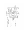
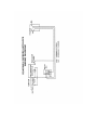
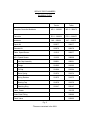
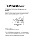
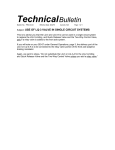
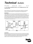
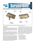
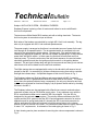
Technical Bulletin
Bulletin No.: PRO-13-01
Effective Date: 8/15/78
Cancels: N/A
Page: 1 of 4
Subject: ANTI-LOCK SYSTEM – ROADWAY EXPRESS
Roadway Express is placing a fleet of tractors and trailers in service with Bendix
Anti-Lock components.
The tractors are White Model RB-2 tandem axle with a trailing dead axle. The tractor
Anti-Lock system is somewhat unique as follows:
Both axles of the tandem are controlled by a single MC-1 Anti-Lock assembly. The tag
axle only is equipped with WS-1 hub mounted speed sensors.
The power supply is arranged so that there is a redundant source of power for the antilock through an air-operated switch. The air-operated switch is connected to the air
source for the spring parking brake release. Consequently, if the parking brakes are
released (by applying air pressure) the anti-lock system is powered up. It also receives
power from the ignition switch. In either case, the anti-lock will self-check as it first
receives power. To hear the air bursts of the self-check sequence, the service brakes
should be applied first and then the ignition switch turned on or the parking brakes
released. The anti-lock indicator lamp will light for two seconds and then go out and two
short bursts of air will be heard from the anti-lock modulator.
The White tractors also are equipped with a relay in the cab which will sense a loss of
ground for the MC-1 or a severing of all three conductors running from cab to controller
and light the indicator lamp. A simplified diagram of this circuit is shown in Fig. 1
The Roadway trailers are Budd and Monon and are equipped with MC-3 controller
modulators with WS-1 speed sensors identical to those used on the tractor. The trailers
do not have the optional indicator lamp; consequently, the only way the trailer anti-lock
system can be checked for functional integrity is by a dynamic check and/or by checking
the fuse in the MC-3.
The Roadway trailers are also equipped with a Bendix two reservoir reduced volume
pneumatic system using an SR-4 trailer supply valve. If any problems occur with the
SR-4, care should be taken not to install the SR-2 by mistake. Only the SR-4 is
designed for the reduced volume system. The primary difference between the SR-2
system and the SR-4 system is that the SR-2 requires separate reservoirs for service
application and for spring brake hold-off, whereas the SR-4 uses both reservoirs for
service application but either will retain air to hold the spring brakes in the release
position in case of the loss of the other. This reduces the total reservoir volume required
to meet “121” requirements. A schematic of the trailer piping is shown in Fig. 2.
A chart showing service piece numbers for servicing the various components is shown in
Fig. 3.
SERVICE PIECE NUMBERS
ROADWAY FLEET
Tractor
Trailer
Complete Controller-Modulator
MC-1 - 289252
MC-3 – 288473
Controller
EC-1 - 289359
EC-3 – 288475
Modulator
M-6 - 289614
M-7 – 288673
Repair Kit
289277
289277
Solenoid Kit
289278
289278
Cable, Speed Sensor
101315
289977
WS-1 Speed Sensor
*
Hub Cap Assembly
*
Flange
*
Fill Cap
*
Stator Spring
*
Spring Retainer
*
Bearing Cap
*
Retaining Ring
101123
288600
288601
288601
291963
291963
291964
291964
291974
291974
291975
291975
291978
291978
293147
293147
Cable, Power
101150
Strain Relief Fitting
289980
Check Valve
229603
Fig. 3
*These are contained in the WS-1