1
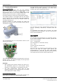
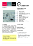
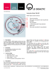
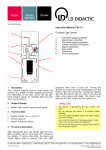
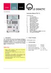
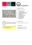
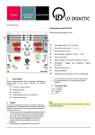
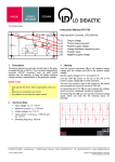
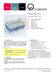
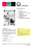
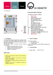
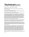
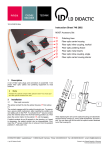
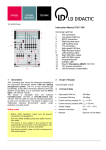
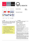
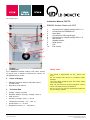
10/14-W2010-Wei Instruction Manual 729 776 1 5 2 6 7 3 EIB/KNX Weather Station with GPS 1 2 3 4 5 6 7 8 9 10 Connection for network voltage 230 V~ L1 Connections for EIB/KNX bus Label plate Connection to PE loop through Connection for network voltage 230 V~ N Rain sensor Weather station Wind sensor Fan Fan control 8 9 10 4 1 Description Safety notes This "EIB/KNX weather station with GPS" serves to teach how a modern multifunction sensor on the EIB/KNX bus works. - The device is appropriate for dry, interior use only! 2 - Do not operate the device if it exhibits visible damage. 3 Scope of Supply EIB/KNX weather station with GPS experimental board Operating instructions Technical Data Supply voltage via KNX Weather station auxiliary voltage: built-in GPS: built-in Auxiliary voltage: 230 V~, 50 Hz Temperature sensor: -30 – +80 °C Wind sensor: 0 – 35 m/s Brightness sensor: 0 – 150,000 lx - Use only safety bridging plugs and intact safety connection leads! - Only use the device for training purposes. Installation in building wiring is prohibited! - Be sure to use only genuine replacement parts for any necessary repairs! LD DIDACTIC GMBH Leyboldstrasse 1 D-50354 Huerth / Germany Phone +49 (0)2233 604-0 Fax +49 (0)2233 604-222 e-mail: [email protected] by LD Didactic GmbH Printed in the Federal Republic of Germany Technical alterations reserved Instruction Manual 4 Functional Description 4.1 Programming On delivery, the device has the bus address 15.15.250. Another address is programmable in the ETS by overwriting the address 15.15.250, or the programming key on the circuit board inside the housing can serve to teach it a different address. Page 2/2 The ETS software, which is not part of the device but is available for purchase separately, e.g. under article number 729 5734, programs the device. Proceed as follows to access the programming button: The weather station's lid engages with the rain sensor on the right and left of the lower edge (see illustration below). Remove the lid from the weather station by unclicking and lifting it. Proceed carefully to avoid severing the cable link between the circuit board in the bottom section and the rain sensor in the lid. You can find a list of all communication objects in the device's operating instructions, enclosed with the device. To incorporate the device into a project, you must integrate the product database. Then you can select the device and incorporate it. The programming key is in the position shown in the following illustration. 4.3 Function 4.3.1 GPS The GPS data and temperature are measured directly. If you cannot establish a GPS connection, position the device near a window. 4.3.2 Temperature The temperature is measured directly. 4.3.3 Rain A moist cloth can simulate rain. 4.3.4 Wind The built-in fan can simulate low wind speeds. Turn the knob to the right for higher wind speeds and correspondingly to the left for lower wind speeds. Please make sure a particular position of the knob does not always lead to the same wind measurement! Then close the housing again by placing the lid over the bottom section. The lid must engage on the right and the left with a clear "click." Remarks After applying the auxiliary voltage, the device is in the initialization phase for a few seconds. During this time, no information is receivable by the bus. The wind measurement, along with all wind switching outputs can be emitted only 60 seconds after applying the supply voltage. 4.2 Programming with ETS At the time of printing of this instruction manual, the device has more than 254 communication objects. LD DIDACTIC GMBH Leyboldstrasse 1 D-50354 Huerth / Germany Phone +49 (0)2233 604-0 Fax +49 (0)2233 604-222 e-mail: [email protected] by LD Didactic GmbH Printed in the Federal Republic of Germany Technical alterations reserved