1
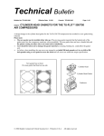
Technical Bulletin
Bulletin No: TCH-001-052
Effective Date: 5/4/04
Subject: Troubleshooting Bendix® inlet check valves on
DDC Series 60 low-emission engines in cases where
the compressor does not build air.
If a DDC Series 60 low emission engine does not build
air, as part of the investigation to find the cause, you
may use the following test to check that the Inlet Check
Valve (ICV) is operating correctly. We recommend
that other less labor-intensive inspections, for example,
to check for a leaking or broken discharge line, be
carried out before conducting this test.
Before beginning this test, read the complete
instructions, and follow all standard safety practices
including, but not limited to, the General Precautions
listed below. With the vehicle parked and the wheels
blocked, shut off the engine. Clean the area around
the ICV of road grime, etc.
Disassembly
To test the ICV, disconnect the hose that supplies air
from the inlet air supply system of the engine to the
ICV. Carefully remove the clamp holding the inlet
hose from the ICV - see Figure 1 for a typical inlet
hose location. Retain the clamp for re-installation.
Note that the ICV has a raised flange on the side
through which the air enters. This test will necessitate
the removal of the ICV from the vehicle, therefore
remove the mounting hardware attaching it to the
vehicle - in some instances it will be easier to remove
the mounting bracket from the engine to assist with
the disassembly.
Test the ICV
Caution: Eye protection equipment must be worn
during this procedure to prevent eye injury in the event
loose material is expelled from the ICV port. On a
test bench securely mount the ICV. Attach a nonpressurized shop air supply line to the delivery side of
the ICV using any necessary fittings. Apply shop air
to the ICV and, with caution, observe the inlet port of
the ICV for air being expelled. A correctly operating
ICV will produce only a small amount of air coming
(backwards) through the valve. A malfunctioning ICV
will release a full burst of air (similar to a blow nozzle).
End the test by shutting off the shop air.
Cancels: TCH-001-052 of 11/11/03
Page: 1 of 2
Inlet hose attaches here
Air flows
in this
direction
through valve
ICV
Figure 1: Inlet Check Valve (location varies by vehicle)
If the ICV is operating normally, reinstall the ICV
by reversing the steps taken to remove it from the
vehicle. Re-attach the inlet hose using the clamp
retained during disassembly, ensuring a good seal
between the hose and the fitting. Consult other
troubleshooting materials and vehicle manuals to help
you investigate why the compressor is not building
air.
In the case of a malfunctioning ICV, where the
compressor does not built air, replace the ICV valve
and the compressor because of possibility of debris in
the system.
GENERAL PRECAUTIONS
IMPORTANT! PLEASE READ AND FOLLOW
THESE INSTRUCTIONS TO AVOID PERSONAL
INJURY OR DEATH:
When working on or around a vehicle, the following
General Precautions should be observed at all times:
1. Park the vehicle on a level surface, apply the
parking brakes, and always block the wheels.
2. Stop the engine when working around the vehicle.
3. Except as directed in these instructions, make
certain to drain the air pressure from all reservoirs
before beginning any work on the vehicle.
(continued over.)
© 2004 Bendix Commercial Vehicle Systems LLC. All rights reserved. 4/2004. Printed in U.S.A.
Bulletin No: TCH-001-052
Subject:
4.
5.
6.
7.
Effective Date: 5/4/04
Cancels: TCH-001-052 of 11/11/03
Page: 2 of 2
Bendix® Inlet Check Valves
As needed, following the vehicle manufacturer’s
recommended procedures, deactivate the
electrical system in a manner that removes all
electrical power from the vehicle.
Typically, when working in the engine
compartment the engine should be shut off.
Where circumstances require that the engine be
in operation, extreme caution should be used to
prevent personal injury resulting from contact
with moving, rotating, leaking, heated, or
electrically charged components.
Never connect or disconnect a hose or line
containing pressure; it may whip. Never remove
a component or plug unless you are certain all
system pressure has been depleted.
Never exceed recommended pressures and always
wear safety glasses.
8.
Do not attempt to install, remove, disassemble or
assemble a component until you have read and
thoroughly understand the recommended
procedures. Use only the proper tools and observe
all precautions pertaining to use of those tools.
9. Use only genuine Bendix replacement parts,
components, and kits. Replacement hardware,
tubing, hose, fittings, etc. should be of equivalent
size, type, and strength as original equipment and
be designed specifically for such applications and
systems.
10. Components with stripped threads or damaged
parts should be replaced rather than repaired.
Repairs requiring machining or welding should
not be attempted unless specifically approved and
stated by the vehicle or component manufacturer.
11. Prior to returning the vehicle to service, make
certain all components and systems are restored
to their proper operating condition.
See vehicle manual, Bendix troubleshooting materials, or visit www.bendix.com for more information.
© 2004 Bendix Commercial Vehicle Systems LLC. All rights reserved. 5/2004. Printed in U.S.A.