1
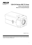
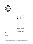
INSTALLATION/OPERATION
EHX*E Series
Explosionproof
Camera Enclosure
C417M-N (4/13)
2
C417M-N (4/13)
Important Safety Instructions
WARNING Potential Electrostatic Charging Hazard
Clean the enclosure surface by gently wiping it with a damp, lint-free cloth before handling or performing maintenance.
1. Read these instructions.
2. Keep these instructions.
3. Heed all warnings.
4. Follow all instructions.
5. Installation and servicing should be done only by qualified service personnel and conform to all local codes.
6. Use only replacement parts Pelco recommends.
7. The installation method and materials should be capable of supporting four times the weight of the enclosure, pan and tilt, camera and lens
combination.
8. The camera and lens combination shall not exceed 9.06 kg (20 lb.
9. For marine applications, the installation shall be in accordance with the Electrical Engineering Regulations of the USCG, Subpart J, C.G 259
(46 CFR Parts 110-113).
10. This enclosure has not been evaluated for use on vessels less than 19.81 m (65 feet) long.
11. Thermal shock of window was conducted at 83°C (181.4°F). If the temperature of the window is greater than 73°C (163.4°F) in the end
product, the thermal shock test must be repeated.
12. Connection facilities must be provided as part of the end product.
13. External or internal grounding connection must be provided for a minimum size conductor of 4 mm2.
14. Earthing or bonding facility for equipotential conductor should be provided inside the terminal compartment near the other connection
facilities.
15. An Ex d IIB stopping box or cable gland must be provided as part of the end product.
16. When included in an end use installation, it must conform to the ATEX and/or IECEX requirements.
17. Rotating machines or other devices which create turbulence shall not be incorporated.
18. Oil filled circuit breakers & contactors shall not be used.
19. At least 20% of the cross sectional area must remain free to permit on unimpeded gas flow.
The product and/or manual may bear the following marks:
This symbol indicates that dangerous voltage constituting a risk of electric shock is present within this unit.
This symbol indicates that there are important operating and maintenance instructions
in the literature accompanying this unit.
CAUTION:
RISK OF ELECTRIC SHOCK.
DO NOT OPEN.
Please thoroughly familiarize yourself with the information in this manual prior to installation and operation.
SCHEDULE DOCUMENT
This document cannot be changed without prior regulatory review.
C417M-N (4/13)
3
Description
The EHX*E Series of nonpressurized, explosionproof camera enclosures is designed to meet the rigorous requirements of explosionproof and
dust-ignitionproof electrical equipment for installation and use in hazardous locations.
The EHX*E Series is constructed of aluminum and available in 4-, 6-, and 8-inch diameters to accommodate most camera and lens combinations.
They come equipped with a unique camera mounting sled and track assembly that allows fast, easy positioning of the camera assembly and can
be securely locked in place.
MODELS
NOTE: The following dimensions represent the interior diameter of the enclosure.
EHX4E
Explosionproof, nonpressurized enclosure, 10.16-cm diameter x 30.48-cm length (4 x 12 in.)
EHX6E
Explosionproof, nonpressurized enclosure, 15.24-cm diameter x 60.96-cm length (6 x 24 in.)
EHX6E-16
Same as EHX6E except 40.64-cm length (16 in.)
EHX8E
Explosionproof, nonpressurized enclosure, 20.32-cm diameter x 60.96-cm length (8 x 24 in.)
PARTS LIST
The following parts are supplied:
Qty Description
1
Enclosure with attached mounting cradle
1
3/16-inch Allen wrench
1
5 mm Allen wrench
2
1/4-20 x 1/2-inch screws
2
Appleton explosionproof sealable fittings (Divisions Only)
1
Pipe plug, 1/2-inch NPT (Divisions Only)
1
Desiccant bag
1
Sealing instructions for fittings
1
Service kit
1
Rear O-ring
4
Rear plate mounting screws
1
Tube of Loctite® 222 low-strength thread locker
A service kit contains spare parts. Please save this kit for future use.
4
C417M-N (4/13)
Installation
1. Attach the cradle to a mount or pan and tilt unit. Follow the instructions supplied with the mount or pan/tilt unit.
2. Remove the enclosure’s rear plate with the 5 mm Allen wrench (supplied).
3. Remove the camera sled from the rail in the body by removing the Allen screw in the end of the sled. Use the 3/16-inch Allen wrench
(supplied).
4. If the camera lens is adjustable, extend the lens to its maximum length.
5. Position the camera over the appropriate mounting holes on the sled and fasten the camera to the sled with the two provided
1/4-20 x 1/2-inch screws. Make sure the lens does not extend beyond the front edge of the sled. This ensures the lens does not contact the
enclosure window after installation.
NOTE: You will need to use elevation blocks (EB1 or EB2) to properly elevate cameras with either a low optical center line or a
large-diameter lens.
6. Replace the camera sled in the enclosure, but do not reinstall the 1/4-20 Allen screw that holds the sled in place.
7. Install the sealing fittings on the rear of the enclosure. If you only need one fitting for wiring, install the pipe plug (supplied) in place of one
of the fittings.
8. Pull the camera video and power wiring through the fitting(s). If applicable, pull the power wiring for the accessories through the fittings.
Refer to Table A on page 6 for 24 VAC applications only (accessories and camera).
9. Attach the video cable to the camera. Connect power to the camera and, if applicable, to the accessories. Refer to the camera installation
manual for detailed instructions.
10. Attach a ground conductor of at least 4mm2 to the 10-32 x 3/8-inch screw on the inside of the rear plate.
GROUND
SCREW
Figure 1. Grounding Location
NOTE: The internal grounding terminal must be used for the equipment grounding connection and the external terminal is for a
supplementary bonding connection where local codes or authorities permit or require such connection.
11. Push the camera sled all the way into the enclosure and fasten the sled with the 1/4-20 Allen screw.
12. Leave the desiccant bag inside the enclosure to absorb moisture.
13. Ensure that the enclosure o-ring is properly seated in the o-ring groove for the rear plate.
14. Replace the rear plate.
15. Apply Loctite to the screws. Loctite 222 low-strength thread locker prevents corrosion between the stainless steel screws and aluminum
enclosure parts. Corrosion causes the parts to seize, resulting in damage to them during disassembly.
16. Tighten the screws using a star pattern.
17. If required, attach a ground wire to the terminal lug on the rear plate.
NOTE: The internal grounding terminal must be used for the equipment grounding connection and the external terminal is for a
supplementary bonding connection where local codes or authorities permit or require such connection.
18. Connect the video and power wiring from the sealing fittings to their sources through fittings and conduit suitable for hazardous locations.
19. (For U.S. and Canada only) Seal the fittings as specified by the manufacturer’s installation instructions. Sealant is not supplied or available
from Pelco.
C417M-N (4/13)
5
0.5 mm2
(20 AWG)
1.0 mm2
(18 AWG)
1.5 mm2
(16 AWG)
2.5 mm2
(14 AWG)
4.0 mm2
(12 AWG)
6.0 mm2
(10 AWG)
10
86
(283)
137
(451)
218
(716)
348
(1142)
551
(1811)
877
(2880)
20
42
(141)
68
(225)
109
(358)
174
(571)
275
(905)
438
(1440)
30
28
(94)
45
(150)
72
(238)
115
(380)
183
(603)
292
(960)
40
21
(70)
34
(112)
54
(179)
86
(285)
137
(452)
219
(720)
50
17
(56)
27
(90)
43
(143)
69
(228)
110
(362)
175
(576)
60
14
(47)
22
(75)
36
(119)
57
(190)
91
(301)
146
(480)
70
12
(40)
19
(64)
31
(102)
49
(163)
78
(258)
125
(411)
80
10
(35)
17
(56)
27
(89)
43
(142)
68
(226)
109
(360)
90
9
(31)
15
(50)
24
(79)
38
(126)
61
(201)
97
(320)
100
8
(28)
13
(45)
21
(71)
34
(114)
55
(181)
87
(288)
110
7
(25)
12
(41)
19
(65)
31
(103)
49
(164)
79
(261)
120
7
(23)
11
(37)
17
(59)
28
(95)
45
(150)
73
(240)
130
6
(21)
10
(34)
16
(55)
26
(87)
42
(139)
67
(221)
140
6
(20)
9
(32)
15
(51)
24
(81)
39
(129)
62
(205)
Maximum distance from transformer to load
Total VA Consumed
Table A. 24 VAC Wiring Distances
These are the recommended maximum distances for 24 VAC applications and are calculated with a 10 percent voltage drop. (Ten percent is
generally the maximum allowable voltage drop for AC-powered devices.) For example, an enclosure that requires 80 VA and is installed 10
meters (35 ft.) from the transformer would require a minimum wire gauge of 20 AWG.
NOTE: Distances are calculated in meters; values in parentheses are feet.
6
C417M-N (4/13)
Operation
MAINTENANCE
REGULAR MAINTENANCE
WARNING: Do not remove the front cover. If you do, Pelco cannot be held responsible for the loss of explosionproof rating, UL listing, or
ability of enclosure to contain an explosion.
Regularly scheduled maintenance will help to prolong the operational life and appearance of the equipment.
1. Periodically look inside the window of the enclosure and check the humidity indicator on the roof. Lavender indicates normal at the desired
level of humidity. Pink indicates excessive dampness and blue indicates dryness. For example, if you want to maintain a humidity level of 20
percent, the 20 percent dot should be lavender.
2. Clean the window regularly with a mild nonabrasive detergent in water to help maintain picture clarity. For a heavily soiled window, use a
glass cleaner.
3. Inspect the sealing fittings frequently for the condition of the sealant.
A service kit containing a rear O-ring and four rear plate mounting screws is included with the enclosure. Use these spare parts if the original
parts are damaged or lost during maintenance or repair of the enclosure.
SERVICE MANUAL
If you need to service the enclosure, obtain a service manual in one of the following ways:
•
Go to Pelco’s web site at www.pelco.com.
•
Contact Pelco’s Literature Department at (559) 292-1981 or (800) 289-9100.
C417M-N (4/13)
7
Specifications
Cable Entry
2 explosionproof sealable fittings
Window
Ground and polished, fully tempered plate glass
Window Viewing Area
EHX4E
EHX6E
EHX6E-16
EHX8E
8.10 cm (3.19 in.) diameter
7.62 cm (3.00 in.) diameter
7.62 cm (3.00 in.) diameter
10.80 cm (4.25 in.) diameter
Window Thickness
EHX4E
EHX6E, EHX6E-16, EHX8E
1.21 cm (0.475 in.) thick
1.27 cm (0.500 in.) thick
Maximum Camera and Lens Size
EHX4E
EHX6E
EHX6E-16
EHX8E
8
Empty Enclosure
30.48 x 8.57 x 6.99 cm
(12.00” L x 3.375” W x 2.75” H)
130.48 x 7.62 cm (2.0” L x 3.0” diameter)
60.96 x 11.11 x 9.53 cm
(24.00” L x 4.375” W x 3.75” H)
60.96 x 12.70 cm (24.0” L x 5.0” diameter)
40.64 x 11.11 x 9.53 cm
(16.00” L x 4.375” W x 3.750” H)
40.64 x 12.70 cm (16.0” L x 5.0” diameter)
60.96 x 13.02 x 14.60 cm
(24.00” L x 5.125” W x 5.75” H)
60.96 x 18.54 cm (24.0” L x 7.3” diameter)
Construction
Aluminum 6061 T6
Contact Pelco by Schneider Electric for dimensions of flameproof joints.
Finish
Gray polyester powder coat
Operating Temperature
-20° to 55°C (-4° to 131°F)
C417M-N (4/13)
Certifications and Ratings
Classified by Underwriters Laboratories Inc. as to explosion and fire hazard only
UL/cUL
Classified by Underwriters Laboratories Inc. as to explosion and fire hazard only
UL 1203 - Edition 4
UL 60079-0 - Edition 5
UL 60079-1 - Edition 6
CSA C22.2 NO. 30
CSA C22.2 NO. 25
CSA C22.2 NO. 60079-0:11
CSA C22.2 NO. 60079-1:11
IEC 60079-0 - Edition 6
IEC 60079-1 - Edition 6
IEC 60079-31 - Edition 1
CENELEC EN 60079-0 - lssue Date 2012
CENELEC EN 60079-1 - lssue Date 2007/07/01
CENELEC EN 60079-31 - lssue Date 2009/12/01
Type 4X enclosure for use in hazardous locations
Class I, Groups C and D – Class II, Groups E, F, and G
Class I, Zone 1, AEx d IIB, Ex d IIB
Empty enclosure with Ex component certificate
DEMKO 03 ATEX 0318166U
0539
II 2 G Ex d IIB Gb
II 2 D, Ex tb IIIC Db IP66
IECEx UL 12.0017U
Ex d IIB Gb
Ex tb IIIC Db IP66
Suitable for marine outside (saltwater) use, for vessels over 19.812 m (65 feet) in length
Maximum o-ring service temperature 70°C (158°F)
Unit Weight
EHX4E
EHX6E
EHX6E-16
EHX8E
C417M-N (4/13)
6.79 kg (15 lb.)
14.04 kg (31 lb.)
12.23 kg (27 lb.)
20.41 kg (45 lb.)
9
M6X20MM
FRONT PLATE
SCREWS
E
M6X25MM
REAR PLATE
SCREWS
C
A B
D
F
1/2” NPT
CONDUIT
ENTRY
G
12.70
(5.00)
H
17.78
(7.00)
22.86
(9.00)
15.87
(6.25)
5.08
(2.00)
7.62
(3.00)
15.24
(6.00)
1/4-20
PEMNUT 2X
EHX4E
MOUNTING CRADLE
EHX6E/8E
MOUNTING CRADLE
DIM
EHX4E
EHX6E-16
EHX6E
EHX8E
A
Ø17.78 (7.00)
Ø20.32 (8.00)
Ø20.32 (8.00)
Ø25.72 (10.13)
B
Ø11.43 (4.50)
Ø16.83 (6.63)
Ø16.83 (6.63)
Ø21.92 (8.63)
C
Ø17.78 (7.00)
Ø22.23 (8.75)
Ø22.23 (8.75)
Ø33.02 (13.00)
D
Ø8.10 (3.19)
Ø7.62 (3.00)
Ø7.62 (3.00)
Ø10.80 (4.25)
E
17.15 (6.75)
19.94 (7.85)
19.94 (7.85)
24.51 (9.65)
F
36.20 (14.25)
47.50 (18.70)
67.82 (26.70)
67.74 (26.67)
G
46.36 (18.25)
57.66 (22.70)
77.98 (30.70)
77.90 (30.67)
H
N/A
21.77 (8.57)
21.77 (8.57)
23.16 (9.12)
Figure 2. EHX*E Series Dimension Drawing
10
C417M-N (4/13)
PRODUCT WARRANTY AND RETURN INFORMATION
WARRANTY
Pelco will repair or replace, without charge, any merchandise proved defective in
material or workmanship for a period of one year after the date of shipment.
Exceptions to this warranty are as noted below:
• Five years:
– Fiber optic products
– Unshielded Twisted Pair (UTP) transmission products
– CC3701H-2, CC3701H-2X, CC3751H-2, CC3651H-2X, MC3651H-2, and
MC3651H-2X camera models
• Three years:
– FD Series and BU Series analog camera models
– Fixed network cameras and network dome cameras with Sarix® technology
– Sarix thermal imaging products (TI and ESTI Series)
– Fixed analog camera models (C20 Series, CCC1390H Series, C10DN Series,
and C10CH Series)
– EH1500 Series enclosures
– Spectra® IV products (including Spectra IV IP)
– Spectra HD dome products
– Camclosure® IS Series integrated camera systems
– DX Series video recorders (except DX9000 Series which is covered for a
period of one year), DVR5100 Series digital video recorders, Digital Sentry®
Series hardware products, DVX Series digital video recorders, and NVR300
Series network video recorders
– Endura® Series distributed network-based video products
– Genex® Series products (multiplexers, server, and keyboard)
– PMCL200/300/400 Series LCD monitors
– PMCL5xxF Series and PMCL5xxNB Series LCD monitors
– PMCL5xxxBL Series LED monitors
• Two years:
– Standard varifocal, fixed focal, and motorized zoom lenses
– DF5/DF8 Series fixed dome products
– Legacy® Series integrated positioning systems
– Spectra III™, Spectra Mini, Spectra Mini IP, Esprit®, ExSite®, ExSite IP, and
PS20 scanners, including when used in continuous motion applications
– Esprit Ti and TI2500 Series thermal imaging products
– Esprit and WW5700 Series window wiper (excluding wiper blades)
– CM6700/CM6800/CM9700 Series matrix
– Digital Light Processing (DLP®) displays (except lamp and color wheel). The
lamp and color wheel will be covered for a period of 90 days. The air filter is
not covered under warranty.
• Six months:
– All pan and tilts, scanners, or preset lenses used in continuous motion
applications (preset scan, tour, and auto scan modes)
Pelco will warrant all replacement parts and repairs for 90 days from the date of
Pelco shipment. All goods requiring warranty repair shall be sent freight prepaid
to a Pelco designated location. Repairs made necessary by reason of misuse,
alteration, normal wear, or accident are not covered under this warranty.
Pelco assumes no risk and shall be subject to no liability for damages or loss
resulting from the specific use or application made of the Products. Pelco’s liability
for any claim, whether based on breach of contract, negligence, infringement of
any rights of any party or product liability, relating to the Products shall not exceed
the price paid by the Dealer to Pelco for such Products. In no event will Pelco be
liable for any special, incidental, or consequential damages (including loss of use,
loss of profit, and claims of third parties) however caused, whether by the
negligence of Pelco or otherwise.
The above warranty provides the Dealer with specific legal rights. The Dealer may
also have additional rights, which are subject to variation from state to state.
If a warranty repair is required, the Dealer must contact Pelco at (800) 289-9100 or
(559) 292-1981 to obtain a Repair Authorization number (RA), and provide the
following information:
1. Model and serial number
2. Date of shipment, P.O. number, sales order number, or Pelco invoice number
3. Details of the defect or problem
If there is a dispute regarding the warranty of a product that does not fall under
the warranty conditions stated above, please include a written explanation with
the product when returned.
Method of return shipment shall be the same or equal to the method by which the
item was received by Pelco.
RETURNS
To expedite parts returned for repair or credit, please call Pelco at (800) 289-9100
or (559) 292-1981 to obtain an authorization number (CA number if returned for
credit, and RA number if returned for repair) and designated return location.
All merchandise returned for credit may be subject to a 20 percent restocking and
refurbishing charge.
Goods returned for repair or credit should be clearly identified with the assigned
CA or RA number and freight should be prepaid.
Revised 10-9-12
The materials used in the manufacture of this document and its components are compliant to the requirements of Directive 2002/95/EC.
REVISION HISTORY
Manual #
C417M-J
Date
8/98
C417M-K
C417M-L
C417M-M
C417M-N
7/99
6/03
2/06
4/13
Comments
Moved all material relating to heaters and blowers to new accessories manual C1495M, including the enclosure accessory wiring distances table. Moved exploded
assembly diagrams, wiring diagrams, and parts lists relating to the enclosures to a new service manual, C417SM. Renumbered sections, figures, and tables.
Added maximum camera and lens sizes. Modified Figure 1, and window and weight specifications. Updated to new format.
Removed references to model EHX10E, updated Certifications and Safeguards and Warnings sections, and added Figure 1.
Revised camera specifications for EHX4E. Added WEEE statement.
Updated for current ATEX certification.
Pelco, the Pelco logo, and other trademarks associated with Pelco products referred to in this publication are trademarks of Pelco, Inc. or its affiliates.
ONVIF and the ONVIF logo are trademarks of ONVIF Inc. All other product names and services are the property of their respective companies.
Product specifications and availability are subject to change without notice.
© Copyright 2012, Pelco, Inc.
All rights reserved.
Pelco by Schneider Electric 3500 Pelco Way Clovis, California 93612-5699 United States
USA & Canada Tel (800) 289-9100 Fax (800) 289-9150
International Tel +1 (559) 292-1981 Fax +1 (559) 348-1120
www.pelco.com www.pelco.com/community