1
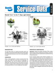
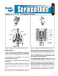
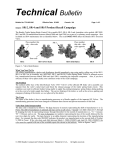
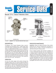
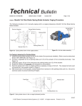
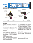
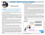
SD-06-1800
Bendix® SL-3™ & SL-4™ Stop Light Switch
7
MACHINE
SCREWS
2
TERMINAL
SCREWS
4
PLUNGER
BODY
9
TERMINAL
SCREWS
1
COVER
7
TERMINAL
CONNECTOR
CONTACTS
3
SPRING
5
WASHER
6
DIAPHRAGM
10
VENT
PLUG
8
COVER
11
SPRING
CONTACT
13
PISTON
14
O-RING
DIAPHRAGM
12
CONTACT
STRIP
15
GASKET
BODY
FIGURE 1 - BENDIX® SL-3™ STOP LIGHT SWITCH
FIGURE 2 - BENDIX® SL-4™ STOP LIGHT SWITCH
DESCRIPTION
PREVENTIVE MAINTENANCE
The stop light switch is an electro-pneumatic switch and
operates in conjunction with the brake valve and stop
lights by completing the electrical circuit when a brake
application is made.
Important: Review the Bendix Warranty Policy before
performing any intrusive maintenance procedures. A
warranty may be voided if intrusive maintenance is
performed during the warranty period.
OPERATION
No two vehicles operate under identical conditions; as
a result, maintenance intervals may vary. Experience is
a valuable guide in determining the best maintenance
interval for air brake system components. At a minimum,
the Bendix® SL-3™ and SL-4™ switches should be inspected
every 6 months or 1500 operating hours, whichever comes
first, for proper operation and electrical connections.
Should the SL-3™ or SL-4™ switch not meet the elements
of the operational tests noted in this document, further
investigation and service of the valve may be required.
When a brake application is made, air pressure from
the brake valve enters the cavity below the diaphragm.
At approximately 5 psi, the air pressure underneath
the diaphragm overcomes the force of the spring and
moves the piston or plunger until the contact points close,
completing the stop light electrical circuit and lighting the
stop lights.
1
TESTING FOR SERVICEABILITY
CLEANING AND INSPECTION
OPERATING TEST
Clean all metal parts in cleaning solvent. Wipe rubber parts
dry with a cloth.
1. Apply the brake valve and note that the stop light lights
before the delivery pressure reaches 7 psi.
2. Release the brake valve and note that the stop light
goes “off”.
LEAKAGE TEST
1. With the brakes fully applied, no leakage is permitted
at the stop light switch. If the stop light switch does
not function as described or if leakage is excessive,
it is recommended that it be replaced with a new unit
or repaired with genuine Bendix® brand replacement
parts available at authorized Bendix parts outlets.
Inspect contact points for pits or wear. If pitting is not too
severe, the points may be reconditioned by filing with a
distributor point file. If points cannot be reconditioned, they
should be replaced. The contact strip in the SL-4™ switch
may be turned over to use the other side of the contacts.
Check the spring for signs of deterioration; Replace if
discolored. The spring in the SL-3™ switch carries the
current of the electrical circuit involved; consequently, in
the case of excessive current, as might be caused by a
short, the spring will be overheated and ruined.
REMOVING
Inspect cover and body. If cracked or damaged, replace.
1. Disconnect the electrical connections at the stop light
switch.
Only genuine Bendix service parts should be used for
replacement.
2. Disconnect the air line to the stop light switch.
ASSEMBLY
3. Remove the stop light switch.
INSTALLING
SL-3™ SWITCH (Figure 1)
1. Install in a convenient location for servicing.
1. Insert terminal screws (2) in the cover (1), making sure
the terminal connector (7) is properly positioned.
2. Install with the pipe tap pointing to the ground and keep
it high for adequate drainage.
2. Secure terminal screws with washers and nuts, or
terminal clips, as the case may be.
3. Connect the stop light switch in series in the stop light
circuit.
3. Place diaphragm (6) in the body.
4. Keep the stop light switch terminals away from frame
members to avoid grounding.
5. Position spring (3) on the plunger.
5. Connect the pipe tap to the brake chamber supply line
so that the stop light switch will operate whether the
foot or hand valve is applied.
DISASSEMBLY
®
™
BENDIX SL-3 SWITCH
1. Place hex portion of body in a vise.
2. Using a large end wrench on cover flats, turn cover (1)
in a counterclockwise direction and remove from body.
3. Remove terminal nuts, terminal screws (2) and terminal
connector (7) from cover.
4. Remove spring (3), plunger (4), washer (5) and
diaphragm (6) from body.
BENDIX® SL-4™ SWITCH
1. Remove two machine screws (7) and remove cover
(8).
2. Remove the terminal nuts and terminals (9) from cover.
3. Remove the vent plug (10) from cover.
4. Remove spring (11), contact strip (12), piston (13) and
o-ring diaphragm (14) from body.
2
4. Position the contact plunger (4) on diaphragm.
6. Place washer (5) on the diaphragm and screw the cover
(1) into the body. Torque to 30 foot pounds. Make certain
the vent hole in the cover is open.
SL-4™ SWITCH (Figure 2)
1. Position terminal screws (9) in the cover (8) and secure
with washers and nuts or terminal clips. Place the vent
plug (10) in cover.
2. Place o-ring diaphragm (14) and piston (13) in the body.
The o-ring diaphragm should be installed with its flat
side adjacent to the piston.
3. Place the gasket (15) in place on the body and contact
strip (12) on the piston (13).
4. Position cover assembly on the gasket and secure with
machine screws. Torque to 20 inch pounds.
TEST OF REBUILT STOP LIGHT SWITCH
Both operating and leakage tests, as indicated under
section entitiled “Testing for Serviceability”, must be made
after rebuilding or repairing the stop light switch. The switch
must meet the following specifications:
1. No leakage is permissible at the stop light switch with
the brakes applied.
2. The stop light switch contact should close with not more
than 7 pounds of air pressure.
3
4
BW1593 © 2011 Bendix Commercial Vehicle Systems LLC, a member of the Knorr-Bremse Group • 6/2011 • All rights reserved