1
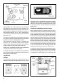
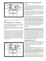
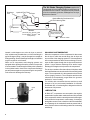
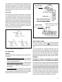
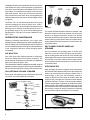
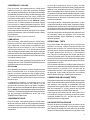
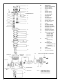
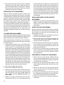
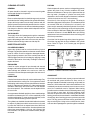
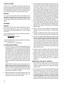
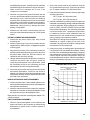
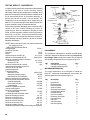
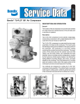
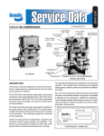
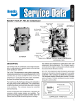
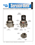
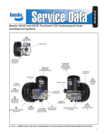
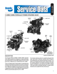
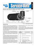
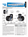
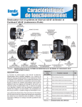
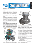
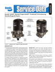
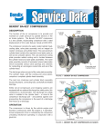
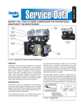
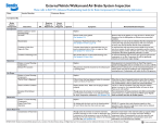
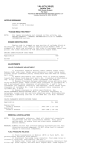
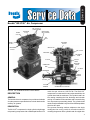
SD-01-331
®
Bendix® BX-2150™ Air Compressor
AIR OUTLET (2)
(1 NOT SHOWN)
WATER
OUTLET
UNLOADER
STOP
WATER INLET
(NOT SHOWN)
AIR
INLET
UNLOADER
PISTON
WATER
OUTLET
INLET VALVE
UNLOADER
PORTS
AIR OUTLET
AIR INTAKE
DISCHARGE
VALVE
PISTON
RINGS
PISTON
REAR END
COVER
CONNECTING
ROD
OIL INLET
CRANKSHAFT
SLEEVE
BEARING
OIL SEAL
ROLLER
BEARING
BX-2150™ AIR COMPRESSOR BELT DRIVE MODEL
DESCRIPTION
GENERAL
The function of the air compressor is to provide and maintain
air under pressure to operate devices in the air brake and/or
auxiliary air systems.
DESCRIPTION
The BX-2150™ compressor is a single cylinder, single stage
reciprocating compressor with a rated displacement of 9.5
CRANKSHAFT OIL PASSAGE
cubic feet per minute at 1250 R.P.M. The BX-2150™
compressor is constructed from two major assemblies, the
cylinder head and the crankcase. The cylinder head is an
iron casting containing the inlet, discharge and unloader
valving. It is installed on the crankcase and is secured using
four cap screws symmetrically placed. The cylinder head
can be, therefore installed in any one of four different positions
which are 90° apart.
Two governor mounting surfaces, adjacent to the single
rectangular inlet cavity, provide a convenient means of
mounting the governor to the cylinder head. One eighth inch
1
1/2” P.T.
WATER
PORT (3)
OUTLET WATER
ONLY
PART NUMBER
1/2” P.T. AIR
DISCHARGE
(2)
SERIAL NUMBER
TYPICAL NAMEPLATE
1/8” P.T.
GOVERNOR
PORT 2 PLACES
AIR INLET
1/2” P.T.
WATER
PORT
BX-2150™ COMPRESSOR CYLINDER HEAD
pipe threads in each of the two governor mounting pads
allow plugging of the unused port or the installation of a
tubing fitting for remote governor mounting. Three 1/2” N.P.T.
ports provide the means for the connection of coolant lines
and are labeled WATER. Two 1/2” N.P.T. discharge ports
are located on the top and side of the cylinder head and are
labeled AIR OUT.
The various mounting and drive configurations required by
the numerous vehicle engine designs are accommodated
by different crankcase castings and crankshafts.
Two methods for cooling the BX-2150™ compressor are
employed. The cylinder head is water cooled using the
engine’s cooling system, while external fins on the crankcase
provide a means for efficient air cooling in that area.
All BX-2150™ compressors utilize the engine’s pressurized
oil system to lubricate internal moving parts.
A nameplate attached to the compressor crankcase identifies
the compressor model and is stamped to indicate the Bendix
part number and serial number.
compression of air is controlled by the compressor unloading
mechanism and the governor. The governor is generally
mounted on the compressor and maintains the brake system
air pressure between a preset maximum and minimum
pressure level.
INTAKE AND COMPRESSION OF AIR (LOADED)
During the down stroke of the piston, a slight vacuum is
created between the top of the piston and the head, causing
the flat circular inlet valve to move off its seat. (Note the flat
square discharge valve remains on its seat.) Atmospheric
air is drawn into the intake cavity and flows past the open
inlet valve and into the cylinder (See Figure 1). As the piston
begins its upward stroke, the air that was drawn into the
cylinder on the down strike is compressed . Air pressure on
the inlet valve plus the force of its spring, returns the inlet
valve to its seat. As the piston continues its upward stroke,
air is compressed and forces the discharge valve away from
its seat. Air flows past the open discharge valve into the
discharge line and on to the reservoirs. (See Figure 2)
As the piston reaches the top of its stroke and starts down,
the discharge valve spring and air pressure in the discharge
line returns the discharge valve to its seat. This prevents the
compressed air in the discharge line from returning to the
OPERATION
GENERAL
The compressor is driven by the vehicle engine and is
operating continuously while the engine is running. Actual
VALVE
STOP
UNLOADER
PISTON
TO
RESERVOIR
INTAKE
INLET
VALVE
VIEW
DISCHARGE
VALVE
PISTON
INTAKE CYCLE
COMPRESSOR MOUNTING/DRIVE CONFIGURATIONS
2
FIGURE 1
VALVE
STOP
UNLOADER
PISTON
INLET
INLET
VALVE
TO
RESERVOIR
DISCHARGE
VALVE
PISTON
FIGURE 2 - COMPRESSION/DISCHARGE CYCLE
cylinder bore as the intake and compression cycle is
repeated.
NON-COMPRESSION OF AIR (UNLOADED)
When air pressure in the reservoir reaches the cut-out setting
of the governor, the governor allows air to flow from the
reservoir into the unloader piston cavity.
The unloader piston moves, in response to air pressure and
drives the inlet valve away from its seat and holds it against
its stop.
With the inlet valve held away from its seat, air compression
is stopped and air is free to move back and forth past the
inlet valve in response to piston travel. System pressure will
eventually drop to the cut-in pressure setting of the governor
due to air usage. When the cut-in pressure is reached, the
governor responds by exhausting air from the unloader piston
cavity. Spring force moves the unloader piston away from
the inlet valve and compression is resumed as the inlet valve
returns to its seat.
COMPRESSOR & THE AIR BRAKE SYSTEM
GENERAL
The compressor is part of the total air brake system, more
specifically, the charging portion of the air brake system. As
a component in the overall system its condition, duty cycle,
proper installation and operation will directly affect other
components in the system.
Powered by the vehicle engine, the air compressor builds
the air pressure for the air brake system. The air compressor
is typically cooled by the engine coolant system, lubricated
by the engine oil supply and has its inlet connected to the
engine induction system.
As the atmospheric air is compressed, all the water vapor
originally in the air is carried along into the air system, as
well as a small amount of the lubricating oil as vapor. If an
air dryer is not used to remove these contaminants prior to
entering the air system, the majority, but not all, will condense
in the reservoirs. The quantity of contaminants that reach
the air system depends on several factors including
installation, maintenance and contaminant handling devices
in the system. These contaminants must either be eliminated
prior to entering the air system or after they enter.
DUTY CYCLE
The duty cycle is the ratio of time the compressor spends
building air to the total engine running time. Air compressors
are designed to build air (run "loaded") up to 25% of the
time. Higher duty cycles cause conditions that affect air
brake charging system performance which may require
additional maintenance. Factors that add to the duty cycle
are: air suspension, additional air accessories, use of an
undersized compressor, frequent stops, excessive leakage
from fittings, connections, lines, chambers or valves, etc.
Refer to Table A in the Troubleshooting section for a guide to
various duty cycles and the consideration that must be given
to maintenance of other components.
COMPRESSOR INSTALLATION
UNLOADER
PISTON
INLET
INLET
VALVE
VALVE
STOP
TO
RESERVOIR
DISCHARGE
VALVE
PISTON
FIGURE 3 - UNLOADED CYCLE
While the original compressor installation is usually
completed by the vehicle manufacturer, conditions of
operation and maintenance may require additional
consideration. The following presents base guidelines.
DISCHARGE LINE
The discharge line allows the air, water-vapor and oil-vapor
mixture to cool between the compressor and air dryer or
reservoir. The typical size of a vehicle's discharge line, (see
column 2 of Table A in the Troubleshooting section) assumes
a compressor with a normal (less than 25%) duty cycle,
operating in a temperate climate. See Bendix and/or other
air dryer manufacturer guidelines as needed.
The discharge line must maintain a constant slope down
from the compressor to the air dryer inlet fitting or reservoir
to avoid low points where ice may form and block the flow. If,
3
The Air Brake Charging System supplies the
Discharge
Line
Optional “Ping” Tank
Air Dryer
compressed air for the braking system as well as other air
accessories for the vehicle. The system usually consists
of an air compressor, governor, discharge line, air dryer,
and service reservoir.
Optional Bendix® PuraGuard® QC™
Oil Coalescing Filter
Compressor
Governor
(Governor plus Synchro valve
for the Bendix® DuraFlo™ 596
Compressor)
Service Reservoir
(Supply Reservoir)
Reservoir Drain
FIGURE 4A - SYSTEM DRAWING
instead, ice blockages occur at the air dryer or reservoir
inlet, insulation may be added here, or if the inlet fitting is a
typical 90 degree fitting, it may be changed to a straight or
45 degree fitting. Shorter discharge line lengths or insulation
may be required in cold climates.
While not all compressors and charging systems are
equipped with a discharge line safety valve this component
is recommended. The discharge line safety valve is installed
in the cylinder head or close to the compressor discharge
port and protects against over pressurizing the compressor
in the event of a discharge line freezeup.
HOLE
DISCHARGE LINE TEMPERATURE
When the temperature of the compressed air that enters
the air dryer is within the normal range, the air dryer can
remove most of the charging system oil. If the temperature
of the compressed air is above the normal range, oil as oilvapor is able to pass through the air dryer and into the air
system. Larger diameter discharge lines and/or longer
discharge line lengths can help reduce the temperature.
The air dryer contains a filter that collects oil droplets, and a
desiccant bed that removes almost all of the remaining water
vapor. The compressed air is then passed to the air brake
service (supply) reservoir. The oil droplets and the water
collected are automatically purged when the governor
reaches its "cut-out" setting.
For vehicles with accessories that are sensitive to small
amounts of oil, we recommend installation of a Bendix®
PuraGuard® QC™ oil coalescing filter, designed to minimize
the amount of oil present.
LUBRICATION
THREAD
FIGURE 4B - DISCHARGE LINE SAFETY VALVE
4
All BX-2150™ compressors are connected to the engine’s
pressurized oil system and a continuous flow of oil is provided
to the compressor, which is eventually returned to the engine.
Oil is fed into the compressor in various ways, for example;
through the rear end cover or the drive end of the crankshaft.
An oil passage in the crankshaft conducts pressurized oil
to the precision sleeve main bearings and to the connecting
rod bearing.
The cylinder bore, connecting rod wrist pin bushing and ball
type main bearing, where used, are splash lubricated. Splash
lubrication is obtained as oil is forced out around the
crankshaft journals by engine oil pressure. See the tabulated
technical data in the back of this manual for specific
requirements.
OLD STYLE HEAD
ADAPTER REQUIRED
GASKET 243430
INLET ADAPTER 297871
COOLING
Air flowing through the engine compartment from the action
of the engine’s fan and the movement of the vehicle assists
in cooling the crankcase. Coolant flowing from the engine’s
cooling system through connecting lines enters the head
and passes through the head’s water jacket and back to the
engine. Proper cooling is important in maintaining discharge
air temperatures below the maximum 400°F recommended.
Figure 5 illustrates the various approved coolant flow
directions. See the tabulated technical data in the back of
this manual for specific requirements.
INLET CHECK
VALVE KIT 104670
FAILURE TO INSTALL ADAPTER 297871
WHEN USING AN INLET CHECK VALVE
WITH THIS STYLE HEAD... WILL
RESULT IN COMPRESSOR DAMAGE
NEW STYLE HEAD
IDENTIFY NEW HEAD BY NOTING
PRESENCE OF PLUGGED BOSS
HERE
ADAPTER NOT REQUIRED
PLUG
IN
OUT
INLET CHECK VALVE KIT 104670
FIGURE 6
OUT
PLUG
INLET CHECK VALVE
PLUG
OUT
IN
IN
FIGURE 5 - WATER CONNECTIONS/FLOW
AIR INDUCTION
GENERAL
There are three methods of providing clean air to the BX-2150™
compressor;
1. Naturally aspirated Local Air Strainer - Compressor
utilizes its own attached air strainer (polyurethane sponge
or pleated paper dry element).
2. Naturally aspirated Engine Air Cleaner - Compressor inlet
is connected to the engine air cleaner or the vacuum
side (engine air cleaner) of the supercharger or
turbocharger.
3. Pressurized induction - Compressor inlet is connected
to the pressure side of the supercharger or turbocharger.
See the tabulated technical data in the back of this manual
for specific requirements for numbers 2 and 3 above.
An inlet check valve is used on some naturally aspirated
BX-2150™ compressors (never with pressurized induction,
see #3 above) to prevent inlet oil misting during the unloaded
cycle.
The new style BX-2150™ compressor head (See Figure 6)
can be identified by the plugged boss on the upper right
hand side. This head only requires kit 104670 to install an
inlet check valve. All other old style BX-2150™ compressor
heads (See Figure 6) require the use of the inlet adapter
297871 and inlet gasket 243430 in addition to the kit 104670.
WARNING!
FAILURE TO INSTALL ADAPTER 297871 WHEN
REQUIRED WILL RESULT IN COMPRESSOR DAMAGE.
The inlet check valve consists of three parts, the inlet gasket,
the inlet check valve reed and the inlet check valve seat
(See Figure 6) during the compression cycle, the inlet check
valve reed is drawn away from its seat uncovering three inlet
holes which allows air to flow into the compressor inlet cavity.
A machined stop in the cylinder head inlet cavity or in the
inlet adapter 297871 limits the travel of the inlet check valve
reed. In the unloaded cycle, the inlet check valve reed rests
on its seat covering the three inlet holes. Air from within the
compressor is prevented from exiting the inlet cavity.
5
Inlet gasket 243430 is required between the inlet check valve
reed and the inlet cavity of new style heads, or between the
inlet check valve reed and the inlet adapter 297871 for old
style heads, as its thickness contributes to the minimum
reed travel required. The pin in the check valve seat must
align with the holes in the check valve, the inlet gasket and
enter the mating hole in the head or the inlet adapter. (Refer
to Figure 6)
CAUTION: If ICV is used with air dryer/aftercooler which
vents the discharge line during its purge cycle, a PR-4™
valve (P/N 103976) is recommended to be installed in the
discharge line to minimize oil passing which can occur in
the combined use of an ICV and a vented discharge line.
See Bulletin No. PRO-08-13 for proper installation of the
PR-4™ valve.
PREVENTATIVE MAINTENANCE
Regularly scheduled maintenance is the single most
important factor in maintaining the air brake charging system.
Refer to Table A in the Troubleshooting section for a guide to
various considerations that must be given to the maintenance
of the compressor and other related charging system
components.
AIR INDUCTION
One of the single most important aspects of compressor
preventive maintenance is the induction of clean air. The
type and interval of maintenance required will vary depending
upon the air induction system used.
The intervals listed under the headings below pertain to typical
highway and street operation. More frequent maintenance
will be required for operation in dusty or dirty environments.
POLYURETHANE SPONGE STRAINER
Every month, 150 operating hours or 5,000 miles, whichever
occurs first, remove and wash all of the parts.
RD. HD. MACHINE SCREW
SCREW
COVER
COVER ASSEMBLY
FILTER
ELEMENT
BAFFLE
MOUNTING
BAFFLE
FILTER
ELEMENT
COVER
FIGURE 8
The strainer element should be cleaned or replaced. If the
element is cleaned, it should be washed in a commercial
solvent or a detergent and water solution. The element
should be saturated in clean engine oil, then squeezed dry
before replacing it in the strainer. Be sure to replace the air
strainer gasket if the entire air strainer is removed from the
compressor intake.
DRY ELEMENT-PLEATED PAPER AIR
STRAINER
Every two months, 800 operating hours or 20,000 miles
whichever occurs first, remove the spring clips from either
side of mounting baffle and remove the cover. Replace the
pleated paper filter and remount the cleaned cover making
sure the filter is in position. Make certain to replace the air
strainer gasket if the entire air strainer is removed from the
compressor intake.
INTAKE ADAPTER
When the engine air cleaner is replaced; Some compressors
are fitted with intake adapters which allow the compressor
intake to be connected to the engine air cleaner, turbo or
super-charger. In this case, the compressor receives a
supply of clean air from the engine air cleaner. When the
engine air filter is changed, the compressor intake adapter
should be checked. If it is loose, remove the intake adapter,
clean the strainer plate, if applicable, and replace the intake
adapter gasket, and reinstall the adapter securely. Check
line connections both at the compressor intake adapter and
at the engine or engine air cleaner. Inspect the connecting
line for kinks and ruptures and replace it if necessary.
STRAINER
SCREW
BODY
BAFFLE
GASKET
BASE PLATE
FIGURE 7
6
FIGURE 9 - COMPRESSOR INTAKE ADAPTER
COMPRESSOR COOLING
Every six months, 1800 operating hours or 50,000 miles,
whichever occurs first, inspect the compressor discharge
port, inlet cavity and discharge line for evidence of restrictions
and carboning. If excessive buildup is noted, thoroughly clean
or replace the affected parts and closely inspect the
compressor cooling system. Check all compressor coolant
lines for kinks and restrictions to flow. Minimum coolant
line size is 3/8" I.D. Check coolant lines for internal clogging
from rust scale. If coolant lines appear suspicious, check
the coolant flow and compare to the tabulated technical data
present in the back of this manual.
Inspect and clean the external air cooling fins on the cylinder
portion of the crankcase. If fins are cracked or broken, replace
the compressor.
Inspect the air induction system for restrictions.
LUBRICATION
Every six months, 1800 operating hours or 50,000 miles,
whichever occurs first; check external oil supply and return
lines, if applicable, for kinks, bends, or restrictions to flow.
Supply lines must be a minimum of 3/16" I.D. and return
lines must be a minimum of 1/2" I.D. Oil return lines should
slope as sharply as possible back to the engine crankcase
and should have as few fittings and bends as possible. Refer
to the tabulated technical data in the back of this manual for
oil pressure minimum valves.
Check the exterior of the compressor for the presence of oil
seepage and refer to the TROUBLESHOOTING section for
appropriate tests and corrective action.
OIL PASSING
All reciprocating compressors currently manufactured will
pass a minimal amount of oil. Air dryers will remove the
majority of oil prior to entrance into the air brake system.
For particularly oil sensitive systems the Bendix® PuraGuard®
QC™ oil coalescing filter can be used in conjunction with a
Bendix air dryer.
If compressor oil passing is suspected, refer to the
TROUBLESHOOTING section and TABLE A for the
symptoms and corrective action to be taken. In addition,
Bendix has developed the "Bendix Air System Inspection
Cup" or BASIC test to help substantiate suspected excessive
oil passing. The steps to be followed when using the BASIC
test are presented in APPENDIX A at the end of the
TROUBLESHOOTING section.
COMPRESSOR DRIVE
Every six months, 1800 operating hours or 50,000 miles,
whichever occurs first, check for noisy compressor operation.
Variations in noise level in conjunction with the compression
and unloaded cycles generally indicate loose or worn drive
components.
On belt drive compressors check for pulley and belt
alignment and tension. Adjust as necessary, paying particular
attention not to overtighten belt tension. Check for loose
and out of aligned pulleys. Adjust or replace as necessary.
Compressor crankshaft keyway damage indicates a loose
pulley and often requires compressor replacement. Main
bearing failures on belt driven compressors often indicate
excessive belt tension.
A thorough inspection, and possible replacement, of drive
components should be made at each compressor change.
Special attention should be given to drive gears and couplings
on compressors which have been operated at high discharge
pressures due to a blocked or frozen discharge line.
Check all compressor mounting bolts and retighten evenly
as necessary. Check the condition of all compressor
mounting bracketry, tighten hardware as necessary, and
replace if damaged.
OPERATIONAL TESTS
Every three months, 900 operating hours or 25,000 miles
whichever occurs first. Vehicles manufactured after the
effective date of FMVSS 121, with the minimum required
reservoir volume, must have a compressor capable of raising
air system pressure from 85-100 p.s.i. in 25 seconds or
less. This test is performed with the engine operating at
maximum governed speed. The vehicle manufacturer must
certify this performance on new vehicles with appropriate
allowances for air systems with greater than the minimum
required reservoir volume.
Check unloader operation by building system pressure to
governor cut-out and note that air compression stops. Reduce
system pressure to governor cut-in and note that air
compression resumes. If the compressor fails to respond
as described, make certain the governor is functioning
properly before repairing or replacing the compressor.
COMPRESSOR AIR LEAKAGE TESTS
Compressor leakage tests need not be performed on a regular
basis. These tests should be performed when; it is suspected
that discharge valve leakage is substantially affecting
compressor build-up performance, or when it is suspected
that the compressor is “cycling” between the load and
unloaded modes due to unloader piston leakage.
These tests must be performed with vehicle parked on a
level surface, the engine not running, the entire air system
completely drained to 0 P.S.I., and the inlet check valve
detail parts removed, if applicable.
UNLOADER PISTON LEAKAGE
Remove the governor and apply shop air pressure to the
1/8" pipe thread unloader port on the governor mounting
pad. Listen for the escape of air at the inlet cavity. An audible
escape of air should not be detected. If any question exists
7
NO.
11
1
2
3
4
5
6
7
8
9
10
11
12
13
14
15
16
17
18
19
20
12
1
13
CYLINDER HEAD ASSY.
2
3
14
4
15
5
16
6
7
17
18
8
9
10
19
20
21
21
22
20
23
24
25
22
CRANKCASE
FRONT BALL
CRANKSHAFT
BEARING
CRANKSHAFT
KEY
23
DESCRIPTION
Cylinder Head Assembly
Governor Gasket
Unloader Bushing
O-Ring
Unloader Piston
Unloader Spring
Inlet Valve Gasket
Inlet Valve Seat
Inlet Valve
Inlet Valve Spring
Inlet Valve Stop
Unloader Piston Stop
Hex Head Screws
O-Ring
Inlet Strainer Gasket
Discharge Valve Stop
Discharge Valve Spring
Discharge Valve
Discharge Valve Seat
Cylinder Head Gasket
Piston Ring Set (STD)
#1 Piston Ring
#2 Piston Ring
Piston Ring Oil
Expander Ring
Piston
Wrist Pin Plug
Wrist Pin
Connecting Rod
Connecting Rod Cap
Lockwasher
Connecting Rod Bolt
O-Ring
Thrust Washer
End Cover Assembly
5/16” MACH.SCREW WITH LOCKWASHER
OIL SEAL
24
25
DRIVE SCREWS
CRANKSHAFT
NUT
NAME PLATE
22
8
NOTE:
SOME APPLICATIONS USE
FRONT AND REAR REF.
SOME FLANGE MOUNTS
WITHOUT BALL BEARINGS.
as to leakage, it is recommended that a genuine Bendix
unloader kit be installed and the cylinder head retested.
DISCHARGE VALVE LEAKAGE
Unloader piston leakage must be repaired before this test is
performed. Leakage past the discharge valve can be detected
by removing the discharge line, applying shop air to the
unloader mechanism and the discharge port and listening
for the escape of air at the compressor inlet cavity. A barely
audible escape of air is generally acceptable; however, if
there is any question as to the leakage rate, it is
recommended that the cylinder head or compressor be
removed and repaired or replaced. With shop air still applied
at the discharge port, apply a soap solution to the valve stop
recess on the top of the head. If leakage is detected, the
cylinder head must be repaired or replaced. Only genuine
Bendix remanufactured compressors or service parts and
kits should be used.
COMPRESSOR TROUBLESHOOTING
IMPORTANT: The troubleshooting contained in this section
considers the compressor as an integrated component of
the overall air brake charging system and assumes that an
air dryer is in use. The troubleshooting presented will cover
not only the compressor itself, but also other charging system
devices as they relate to the compressor.
WARNING! PLEASE READ AND FOLLOW
THESE INSTRUCTIONS TO AVOID
PERSONAL INJURY OR DEATH:
When working on or around a vehicle, the following
general precautions should be observed at all times.
1. Park the vehicle on a level surface, apply the
parking brakes, and always block the wheels.
Always wear safety glasses.
2. Stop the engine and remove ignition key when
working under or around the vehicle. When
working in the engine compartment, the engine
should be shut off and the ignition key should be
removed. Where circumstances require that the
engine be in operation, EXTREME CAUTION should
be used to prevent personal injury resulting from
contact with moving, rotating, leaking, heated or
electrically charged components.
3. Do not attempt to install, remove, disassemble or
assemble a component until you have read and
thoroughly understand the recommended
procedures. Use only the proper tools and observe
all precautions pertaining to use of those tools.
4. If the work is being performed on the vehicle’s air
brake system, or any auxiliary pressurized air
systems, make certain to drain the air pressure
from all reservoirs before beginning ANY work on
the vehicle. If the vehicle is equipped with an
AD-IS™ air dryer system or a dryer reservoir module,
be sure to drain the purge reservoir.
5. Following the vehicle manufacturer’s
recommended procedures, deactivate the electrical
system in a manner that safely removes all electrical
power from the vehicle.
6. Never exceed manufacturer’s recommended
pressures.
7. Never connect or disconnect a hose or line
containing pressure; it may whip. Never remove a
component or plug unless you are certain all
system pressure has been depleted.
8. Use only genuine Bendix® replacement parts,
components and kits. Replacement hardware,
tubing, hose, fittings, etc. must be of equivalent
size, type and strength as original equipment and
be designed specifically for such applications and
systems.
9. Components with stripped threads or damaged
parts should be replaced rather than repaired. Do
not attempt repairs requiring machining or welding
unless specifically stated and approved by the
vehicle and component manufacturer.
10. Prior to returning the vehicle to service, make
certain all components and systems are restored to
their proper operating condition.
11. For vehicles with Antilock Traction Control (ATC),
the ATC function must be disabled (ATC indicator
lamp should be ON) prior to performing any vehicle
maintenance where one or more wheels on a
drive axle are lifted off the ground and moving.
COMPRESSOR REMOVAL & DISASSEMBLY
GENERAL
The following instructions are presented here for reference.
Removal and disassembly of the compressor is not
recommended unless the appropriate service parts and/or
kits are on hand.
REMOVAL
These instructions are general and are intended to be a
guide, in some cases additional preparations and precautions
are necessary.
1. Block the wheels of the vehicle and drain the air pressure
from all the reservoirs in the system.
2. Drain the engine cooling system and the cylinder head
of the compressor. Identify and disconnect all air, water
and oil lines leading to and from the compressor.
3. Remove the governor and any supporting bracketry
attached to the compressor and note their positions on
the compressor to aid in reassembly.
4. Remove the discharge port and inlet cavity fittings, if
applicable, and note their position on the compressor
to aid in reassembly.
5. Remove the flange or base mounting bolts and remove
the compressor from the vehicle.
9
6. Remove the drive gear(s) or pulley from the compressor
crankshaft using a gear puller. Inspect the pulley or
gear and associated parts for visible wear or damage.
Since these parts are precision fitted, they must be
replaced if they are worn or damaged.
PREPARATION FOR DISASSEMBLY
cylinder head body be replaced if it is determined that
the unloader piston bushing requires replacement. If
this is not possible, the bushing can be pressed out of
the head using the same procedure presented in Step
2 of this disassembly section. NOTE: if the bushing is
pressed out and the cylinder head casting is damaged
in the process, cylinder head repair is not recommended
Pressing in the replacement bushing will result in air or
water leakage.
Remove road dirt and grease from the exterior of the
compressor with a cleaning solvent. Before the compressor
is disassembled, the following items should be marked to
show their relationship when the compressor is assembled.
Mark the rear end cover in relation to the crankcase. Mark
the cylinder head in relation to the crankcase. Mark the
base plate or base adapter in relation to the crankcase.
CRANKCASE BASE PLATE OR ADAPTER
DISASSEMBLY
A convenient method to indicate the above relationship is to
use a metal scribe to mark the parts with numbers or lines.
Do not use a marking method that can be wiped off or
obliterated during rebuilding, such as chalk. Remove all
compressor attachments which have not been previously
specified.
CONNECTING ROD DISASSEMBLY
CYLINDER HEAD DISASSEMBLY
Remove the four cylinder head cap screws and tap the head
with a soft mallet to break the gasket seal. Scrape off any
gasket material from the cylinder head and crankcase.
Before disassembling the discharge valve mechanism,
measure and record the discharge valve travel (from closed
to completely open).
1. If the measured discharge valve travel DOES NOT
EXCEED .032 inches, the discharge valve stop need
not be removed. It is recommended that the cylinder
head body be replaced if the discharge valve stop requires
replacement. In the event this is not possible the following
procedure can be followed: Using a 9/16” Allen wrench,
remove the discharge valve seat, valve, and valve spring.
To remove the discharge valve stop, support the machined
surface of the cylinder head on an arbor press bed and
gently press the stop from the top of the head and out
the bottom. Be sure to allow sufficient clearance for the
stop between the press bed and the bottom of the
cylinder head. The valve stop bore in the cylinder head
must be inspected for excessive scoring. A new cylinder
head body must be used if scoring is excessive.
2. Remove the unloader stop and o-ring.
3. Remove the unloader piston and o-ring.
4. Insert the lugs of a spanner wrench into the holes of the
inlet valve stop and remove the inlet valve stop along
with the inlet valve, valve seat, unloader gasket and
spring. (NOTE: Reference Williams adjustable face
spanner #483.)
5. Inspect the unloader piston bushing for nicks, wear,
corrosion and scoring. It is recommended that the
10
1. Remove the cap screws securing the base plate or base
adapter. Tap with soft mallet to break the gasket seal.
Scrape off any gasket material from crankcase and
plate adapter.
Before removing the connecting rod, mark the connecting
rod and its cap. The connecting rod is matched to its own
cap for proper fit, and the cap must be reinstalled in the
same position on the rod.
1. Straighten the prongs of the connecting rod bolt locks
and remove the bolts and bearing cap.
2. Push the piston with the connecting rod attached out
the top of the cylinder of the crankcase. Replace the
bearing cap on the connecting rod.
3. Remove the piston rings from the piston. If the piston is
to be removed from the connecting rod, remove the
wrist pin teflon plugs and press the wrist pin from the
piston and connecting rod.
4. If the piston is removed from the rod, inspect the wrist
pin bore or the bronze wrist pin bushing in the connecting
rod. If excessive wear is noted or suspected, replace
the connecting rod.
COMPRESSOR CRANKCASE DISASSEMBLY
1. Remove the key or keys from the crankshaft and any
burrs from the crankshaft where the key or keys were
removed. (NOTE: Through drive compressors may have
a crankshaft key at both ends.)
2. Remove the four cap screws and lockwashers or nuts
and lockwashers that secure the rear end cover to the
crankcase.
3. Remove the rear end cover, thrust bearing and end
cover o-ring taking care not to damage the bearing if
present in the end cover.
4. If the compressor has ball type main bearings, press
the crankshaft and ball bearings from the crankcase,
then press the ball bearings from the crankshaft.
5. Press the oil seal out of the compressor crankcase if
so equipped.
CLEANING OF PARTS
PISTONS
GENERAL
Check the piston for scores, cracks, or enlarged ring grooves;
replace the piston if any of these conditions are found.
Measure the diameter of the top of the piston and the top
two ring lands. (Compare to cylinder bore and piston
diameters to be sure the diametrical clearance is between
.0128 inch minimum and .0177 inch maximum.)
All parts should be cleaned in a good commercial grade
solvent and dried prior to inspection.
CYLINDER HEAD
Remove carbon deposits from the discharge cavity and rust
and scale from the cooling cavities of the cylinder head body.
Scrape all foreign matter from the body surfaces and use
shop air pressure to blow the dirt particles from the cavities.
Clean carbon and dirt from the inlet and unloader passages.
Use shop air to blow the carbon and dirt deposits from the
unloader passages.
OIL PASSAGES
Thoroughly clean all oil passages through the crankshaft,
crankcase, end covers, and base plate or base adapter.
Inspect the passages with a wire to be sure they are clear.
Blow the loosened foreign matter out with shop air.
INSPECTION OF PARTS
Check the fit of the wrist pin to the piston. The wrist pin
should be a light press fit in the piston. This clearance should
not exceed .0006 inch. If the wrist pin is a loose fit, the
piston and pin assembly should be replaced. Check the fit
of the wrist pin in the connecting rod by rocking the piston.
Conn rod wrist pin .0009 max. Replace the connecting rod if
excessive clearance is found. NOTE: Wrist pin bushing
replacement is not recommended for those connecting rods
which incorporate them.
Check the fit of the piston rings in the piston ring grooves.
Check the ring gap with the rings installed in the cylinder
bores. Refer to Figure 11 for correct gap and groove
clearances.
CYLINDER HEAD BODY
Inspect the cylinder head for cracks and obvious physical
damage. Pay particular attention to the area around coolant
ports for cracks. Check for stripped or damaged threads.
Apply shop air pressure to one of the coolant ports with all
others plugged, and check for leakage by applying a soap
solution to the exterior of the body. If leakage is detected,
replace the head.
END COVERS
Check for cracks, stripped oil port threads and external
damage; and if noted, replace the end cover. If the crankshaft
main bearings are installed in the end cover, check for
excessive wear and flat spots and replace the end cover if
necessary.
CRANK CASE
Check all crankcase surfaces for cracks and damage. Pay
particular attention to cooling fins. On compressors where
ball bearing main bearings are used the difference between
the O.D. of the outer race and the I.D. of the crankcase hole
should be .0000 inch to .0015 inch loose. This is to maintain
the correct press fit. The crankcase must be replaced if the
fit is too loose.
On compressors fitted with precision, sleeve main bearings
the difference between the O.D. of the crankshaft journal
and the main bearing I.D. must not exceed .004 inch, or the
end cover and main bearing must be replaced.
The cylinder bore should be checked with inside micrometers
or calipers. Cylinder bores which are scored or out of round
by more than .0005 inch or tapered more than .0005 inch
should be rebored or honed oversize. Oversized pistons and
piston rings are available in .010 inch, .020 inch and .030
inch oversizes. The cylinder bore must be smooth, straight,
and round.
PISTON RING
OIL RING
PISTON
RING
.002
.004
.0015
.0035
CORRECT GAP CLEARANCE
WITH RINGS IN CYLINDER
OIL RING
.004
.012
FIGURE 11 - CORRECT GROOVE CLEARANCE
CRANKSHAFT
Check the crankshaft threads, keyways, tapered ends and
all machined and ground surfaces for wear, scores, or
damage. Standard crankshaft connecting rod journals are
between 1.2500 inches and 1.249 inches in diameter. If the
crankshaft journals are excessively scored or worn or out of
round, the crankshaft must be replaced. Main bearing
journals must be maintained so the ball bearings are a snug
fit or so that no more than .004 inch clearance exists
between the precision sleeve main bearing and the main
bearing journals on the crankshaft. In crankshafts fitted with
oil seal rings, the oil seal ring groove or grooves must not be
worn. The ring groove walls must have a good finish and
they must be square. Using a wire or similar device, check
to be sure the oil passages are open through the crankshaft.
11
CONNECTING RODS
™
The BX-2150 compressor connecting rod does not
incorporate replaceable crankshaft journal bearing inserts
and must be replaced if excessively worn. Clearance between
the crankshaft journal and the connecting rod bearing must
not be less than .001 inch or more than .0025 inches.
REPAIRS
It is generally recommended that genuine Bendix service
parts and maintenance kits be used whenever the
compressor is disassembled. A listing of the most common
kits and their contents can be found in the back of this
manual.
ASSEMBLY
TORQUES
All torques specified in this manual are assembly torques
and can be expected to fall off after assembly is
accomplished. Do not retorque after initial assembly
torques fall.
To convert pound inches of torque to pound feet of torque,
divide inch pounds by 12.
pound inches = pound feet
12
To convert pound feet of torque to pound inch of torque,
multiply pound feet by 12.
pound feet x 12 = pound inches
CYLINDER HEAD ASSEMBLY
1. If the discharge valve stop was removed and must be
replaced, a sealant such as “LOCKTITE RETAINING
COMPOUND #75”, must be applied to the stop and its
corresponding bore in the cylinder head. Before applying
the sealant, make certain that the press fit between the
discharge valve stop outside diameter and the valve stop
bore in the cylinder head is a minimum of .0013 inches
and a maximum of .0028 inches. If this fit cannot be
maintained, a new cylinder head body must be used.
Be sure to completely support the outside top of the
cylinder head casting, while pressing in the replacement
stops.
IMPORTANT: The cylinder head must be supported in a
fashion that allows the machined head surface to be
parallel to the arbor press bed and perpendicular to the
press ram. This is necessary to permit the discharge
valve stop to be installed squarely in its bore and to
minimize the possibility of “cocking”.
2. Install the discharge valve spring, discharge valve and
valve seat. Using a 9/16” Allen wrench torque the
discharge valve seat to 70-90 pound feet.
12
3. Test for leakage by the discharge valve. Apply 100 psi of
air pressure through the cylinder head discharge port
and apply a soap solution to the discharge valve and
seat. A slight leakage in the form of soap bubbles is
permissible. If excessive leakage is found, leave the air
pressure applied and with the use of a fiber or hardwood
dowel and a hammer, tap the discharge valve off its seat
several times. This will help the valve to seat and should
reduce the leakage. With the air pressure still applied at
the discharge port of the cylinder head, check for leakage
around the discharge valve stop exposed on the top of
the cylinder head casting. No leakage is permitted.
4. If the unloader piston bushing was removed, press in a
new bushing following the same pressing procedures
given in Step 1. The inside diameter of the unloader piston
bushing must be between .7497 inches and .7460 inches
after pressing.
5. Using a 3/8" Allen wrench install the unloader piston
stop and o-ring in the head. Torque to 175-225 pound
inches.
6. Install the unloader piston and o-ring in the head so that
the short stem of the piston rests on the unloader stop.
7. Install the unloader piston spring, small end first, on the
stem of the unloader piston. Install the metal (copper)
inlet valve gasket so that it rests on the shoulder of the
inlet valve cavity. Install the inlet valve seat on top of the
inlet valve gasket with its beveled side visible. Make
certain the large coils of the piston spring rest within the
recess of the inlet valve seat on the side opposite the
bevel. Install the inlet valve so that it rests on the beveled
side of the valve seat.
8. Install the inlet valve spring on the inlet valve stop and
install the stop in the head. Using a spanner wrench,
torque the inlet valve stop to between 70-90 pound feet.
9. Apply 100 psi air pressure to the unloader port of the
governor mounting pad and note the inlet valve is driven
away from its seat. Using a soap solution, test for air
leakage at the unloader piston stop. No leakage is
permitted.
CRANKCASE & CRANKSHAFT ASSEMBLY
1. If the compressor requires a drive end crankshaft oil seal,
press it into the crankcase until it is flush with the
crankcase casting. Using clean oil lubricate the sealing
lips of the seal.
2. If the compressor uses a ball type main bearing, press
the ball bearing onto the correct end of the crankshaft.
Position the ball bearing and the crankshaft in the
crankcase, making sure the drive end of the crankshaft
is positioned in the crankcase as marked before
disassembly. NOTE: In the case of compressors with a
rear main ball bearing, make certain to install the thrust
bearing in the crankcase before pressing the crankshaft
3. Place the o-ring seal in the groove around the rear end
cover or in the crankcase proper in the event a rear main
ball bearing is in use. If the rear end cover contains a
precision sleeve bearing that serves as the crankshaft
main bearing, make certain to install the thrust bearing.
Install the end cover in the position as marked before
disassembly, taking care not to damage the sleeve
bearing, if so equipped.
4. Install the four cap screws or nuts that secure the rear
end cover to the crankcase and torque to 175-225 pound
inches.
PISTON & CONNECTING ROD ASSEMBLY
1. Prelubricate the piston, piston rings, wrist pin and
connecting rod.
2. Install the piston rings in the correct location with the
ring pipmarks up. (Refer to Figure 11) Stagger the position
of the ring gaps.
3. Align the wrist pin bore of the connecting rod with the
piston bores and install the wrist pin to secure the rod to
the piston. Make certain the TEFLON “buttons” are
installed in each end of the wrist pin.
4. Using an automotive type ring compressor or similar tool,
compress the piston rings and gently install the
connecting rod and piston in the cylinder bore. Install
the connecting rod cap on the connecting rod in the
same position as marked during disassembly.
5. Secure the rod cap to the rod using the two cap screws
and special lockwashers. Torque the cap screw to
between 120-140 pound inches and bend the tabs of the
lockwashers until they are firmly against the flats of the
hex head of the cap screws.
BASE PLATE OR BASE ADAPTER ASSEMBLY
1. Position the base plate or base adapter gasket on the
crankcase and install the base plate or base adapter as
marked before disassembly.
2. Install the cap screws that secure either the crankcase
base plate or crankcase mounting base adapter. Torque
the cap screws evenly to the appropriate valve:
Base plate 85-115 pound inch mounting base adapter 175225 pound inches.
FINAL COMPRESSOR ASSEMBLY
1. Place the cylinder head gasket on the crankcase and
position the head on the crankcase as marked during
disassembly. A gasket sealer is neither required or
recommended.
2. Secure the cylinder head to the crankcase using the
four cylinder head cap screws. Torque the cap screws
in a “X” pattern to between 175-225 pound inches.
3. Using a thread sealant install all necessary pipe plugs
and torque as follows:
1/8" P.T. plugs - 85-105 pound inches
1/2” P.T. plugs - 200-270 pound inches
4. Install all crankshaft keys making certain to support the
crankshaft to avoid bearing damage. Install the crankshaft
nut where applicable. When installing drive couplings,
gears or pulleys, DO NOT EXCEED 120 foot pounds
torque on the crankshaft nut. The self locking crankshaft
nut used on the BX-2150™ compressor requires that it
be installed so that the narrow castellation slots are
toward the end of the crankshaft and not against the
pulley, coupling or gear that the nut retains.
Some BX-2150™ through drive compressors require the
installation of a spline coupling on the rear of the
crankshaft. The cap screw securing the coupling should
be torqued to 175-225 inch pounds.
5. Using covers, plugs, or masking tape to protect all ports
if compressor is not to be installed immediately. Protect
the ends of the crankshaft against damage by wrapping
with masking tape or friction tape. The open bottom of a
vertical engine lubricated compressors should be
protected against the entrance of dirt during handling or
storage, by installing a temporary cover over the base.
COMPRESSOR BUILD-UP TIME CHART
400
BUILD-UP TIME (SECONDS)
and ball bearing into place. Carefully press the crankshaft
and ball bearing into the crankcase using an arbor press.
Make certain not to damage the oil seal, if the
compressor is so equipped.
COMPRESSOR BUILD-UP TIME
0-120 PSI
6900 CUBIC INCH RESERVOIR
300
200
100
0
1200
1500
1800
2100
2400
2700
COMPRESSOR SPEED (RPM)
3000
13
TESTING REBUILT COMPRESSOR
WATER PORT
In order to properly bench testa compressor under operating
conditions, a test rack for correct mounting, cooling,
lubricating, and driving the compressor is necessary. Such
tests are not compulsory if the unit has been carefully rebuilt
by an experienced person. A compressor efficiency or
build-up test can be run which is not too difficult. The
compressor must be connected to an oil supply line of at
least 15 P.S.I. pressure during the test and an oil return line
must be installed to keep the crankcase drained.
1
14
DISCHARGE
PORT
WATER PORT
GOVERNOR
MOUNTING PAD
2
O-RING
13
4
Connect the compressor discharge port to a reservoir with a
volume of 650 cubic inches, including the volume of
connecting line. With the compressor operating at 1800
R.P.M., the time required to raise the reservoir(s) pressure
from 0 P.S.I. to 100 P.S.I. should not exceed 20 seconds.
*During this test, the compressor should be checked for
gasket leakage and noisy operation, as well as unloader
operation and leakage.
*NOTE: With no inlet check valve or air strainer attached to
the compressor inlet.
TABULATED TECHNICAL DATA
Average weight
33 lbs.*
Number of cylinders
1
Bore size
3.375"
Stroke
1.468"
Displacement at 1250 R.P.M.
9.5 C.F.M.
Maximum recommended R.P.M.
3000 R.P.M.
Minimum coolant flow (water cooled) at
Maximum R.P.M.
2.5 G.P.M.
Minimum R.P.M.
.5 G.P.M.
Minimum coolant flow (air-cooled)
N/A
Approximate horsepower required at
1250 R.P.M. at 120 PSIG
(naturally aspirated)
1.7
Turbocharge limits
Maximum R.P.M.
2200 R.P.M.
Maximum pressure (gauge)
15 PSIG
Maximum inlet air temperature
250° F
Maximum discharge air temperature
400° F
Minimum pressure required to unload
(naturally aspirated)
60 PSIG
(with inlet check valve)
85 PSIG
(turbocharged)
85 PSIG
Minimum oil pressure required
at engine idling speed
5 PSIG
Minimum oil pressure required at
any engine speed
15 PSIG
Oil capacity of self-lubricated model
N/A
Minimum discharge-line size
1/2" I.D.
Minimum coolant-line size
3/8" I.D.
Minimum oil-supply line size
3/16" I.D.
Minimum oil-return line size
1/2" I.D.
Minimum air-inlet line size
5/8" I.D.
Minimum unloader-line size
3/16" I.D.
*Installed weight determined by final mounting configuration.
3
12
10
9
7
11
8
6
5
14
FIGURE 12
UNLOADER KIT
The unloader kit is designed for use when unloader piston
leakage is detected as described under the Compressor
Air Leakage Tests section of this manual. The kit contains
the following components which are keyed to Figure 12.
Qty.
1
1
Description
Unloader stop assembly
Unloader piston assembly
Key
3
4
MAJOR MAINTENANCE KIT
The major maintenance kit is designed to rebuild the
BX-2150™ compressor head assembly and contains the
following parts which are keyed to Figure 12.
Qty.
1
1
1
1
1
1
1
1
1
1
1
1
1
Description
Key
Unloader Kit
Discharge Valve
Governor Gasket
Strainer Gasket
Discharge Valve Spring
Cylinder Head Gasket
Unloader Spring
Inlet Valve Gasket
Discharge Valve Seat
Inlet Valve Stop
Inlet Valve
Inlet Valve Seat
Inlet Valve Spring
3&4
12
1
2
13
14
10
9
11
5
7
8
6
DO NOT USE THIS PAGE
BW1971 STARTS HERE.
SEE OTHER DOCUMENT.
15
36
BW1424 © 2004 Bendix Commercial Vehicle Systems LLC All rights reserved. 9/2004 Printed in U.S.A.