1
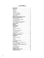
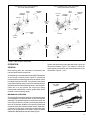
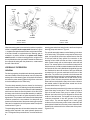
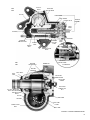
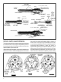
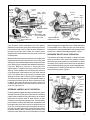
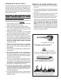
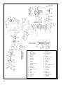
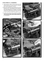
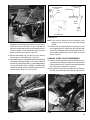
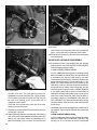
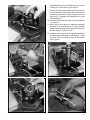
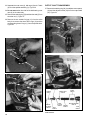
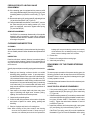
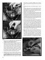
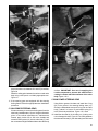
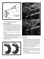
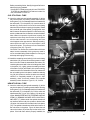
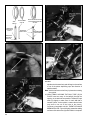
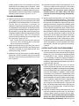
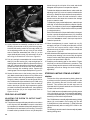
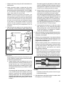
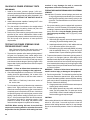
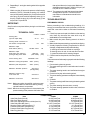
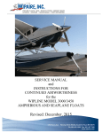
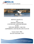
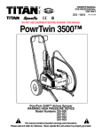
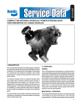
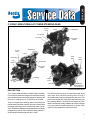
SD-30-4265 ® C-300N/C-500N HYDRAULIC POWER STEERING GEAR OUTPUT SHAFT C-300N NAME PLATE OIL RETURN OIL SUPPLY OUTPUT SHAFT ADJUSTING SCREW NAMEPLATE C-500N VALVE BODY OIL RETURN OIL SUPPLY INPUT SHAFT SIDE COVER ADJUSTING SCREW STEERING LIMITING STEM PLUG VALVE BODY OUTPUT SHAFT HOUSING DESCRIPTION The Compact 300N and 500N (C-300N/C-500N), Hydraulic Power Steering Gears are designed for medium and heavy duty vehicles with front axle weight ratings of 6,000 to 9,000 lbs for the C-300N and up to 15,000 lbs for the C-500N. They are integral power steering gears incorporating the mechanical and hydraulic actuation and control components in a single cast housing which serves as the power cylinder. The C-300N and C-500N power steering gears are very similar in appearance with the major difference being that the C500N is proportionately larger than the C-300N. C-300N PRESSURE RELIEF & BYPASS VALVE CAP NUT POWER STEERING GEAR The vehicles steering column is coupled to the gear at the input shaft which transmits steering effort through a recirculating ball screw (spindle assembly) and piston. The piston is an integral part of the power assist and also acts as a steering damper. The direction and degree of power assist is controlled by a rotary hydraulic valve which is integral to the input shaft and spindle assembly. An engine driven hydraulic pump supplies the flow and pressure. 1 SD-30-4265 TABLE OF CONTENTS DESCRIPTION .............................................................. 1 OPERATION .................................................................. 1 General ........................................................................ 1 Mechanical .................................................................. 3 Hydraulic ..................................................................... 4 Rotary Control Valve .................................................... 4 Steering Limiting Valve ................................................ 7 Pressure Relief Valve ................................................... 8 Bypass Valve ............................................................... 8 POWER STEERING IDENTIFICATION ......................... 8 PREVENTIVE MAINTENANCE ..................................... 8 Power Steering Oil ....................................................... 8 Draining and Filling the System ................................... 8 Oil Change Intervals .................................................... 8 Output Shaft Sector Teeth Adjustment .......................... 8 Output Shaft Boot & Dust Seals ................................... 9 CAUTION NOTE ........................................................... 9 REMOVAL ..................................................................... 9 SPECIAL TOOLS .......................................................... 9 DISASSEMBLY .............................................................11 General .......................................................................11 Output Shaft Removal .................................................11 Piston ........................................................................ 13 Main Housing & Side Cover ....................................... 15 Valve Body & Spindle ................................................ 16 Output Shaft .............................................................. 18 Pressure Relief & Bypass Valve ................................ 18 Spindle ...................................................................... 18 CLEANING & INSPECTION ........................................ 19 REASSEMBLY ............................................................. 19 General ...................................................................... 19 Valve Body & Spindle ................................................ 19 Piston ........................................................................ 21 Housing ..................................................................... 24 Output Shaft & Side Cover ......................................... 25 ADJUSTMENT ............................................................ 26 Piston to Output Shaft Gear Backlash ........................ 26 Stroke Limiting Stem .................................................. 27 ON-VEHICLE POWER STEERING TESTS ................ 27 Preliminary ................................................................ 28 Pressure Relief Valve ................................................. 28 Internal Leakage ........................................................ 28 TECHNICAL DATA ...................................................... 29 ASSEMBLY TORQUE CHART .................................... 29 TROUBLESHOOTING ................................................ 30 2 PISTON OVER OUTPUT SHAFT MOUNTING (LEFT HAND THREAD SPINDLE) SPINDLE ASSEMBLY INPUT SHAFT PISTON UNDER OUTPUT SHAFT MOUNTING (RIGHT HAND THREAD SPINDLE) STEERING WHEEL OUTPUT SHAFT SPINDLE ASSEMBLY INPUT SHAFT STEERING WHEEL PISTON VEHICLE RIGHT TURN PITMAN ARM PITMAN ARM PISTON OUTPUT SHAFT VEHICLE LEFT TURN FIGURE 1 - MECHANICAL OPERATION OPERATION GENERAL Both steering gears are composed of mechanical and hydraulic power assist components. Actual steering is accomplished mechanically. Effort applied at the vehicles steering wheel results in mechanical movement within the steering gear which causes the vehicle to change its direction of travel. The hydraulic power assist components function solely to reduce the mechanical effort required to turn the vehicles steering wheel. Loss of hydraulic power will in no way prevent the vehicle from being maneuvered mechanically, however greater effort will be required to turn the steering wheel. MECHANICAL OPERATION The turning effort exerted by the driver on the steering wheel is transmitted to the input shaft which is part of the spindle assembly. The spindle and piston function like a screw and nut through the action of a chain of recirculating balls that serve as an interface. Rotation of the spindle causes axial movement of the piston within the power cylinder. Gear teeth, cut directly into the piston, mesh with corresponding gear teeth on the output shaft. As the piston moves, the output shaft and the attached pitman arm are rotated. Figure 1 Spindle and piston sets are provided with either right or left hand screw threads. Figure 2 The manner in which the steering gear is mounted on the vehicle determines of the thread used. Figures 1, 2 & 3 LEFT HAND THREAD INPUT SHAFT BALL SCREW RIGHT HAND THREAD FIGURE 2 - SPINDLE ASSEMBLIES 3 TIE ROD ARM TIE ROD DRAG LINK PITMAN ARM STEERING ARM SPINDLE ASSEMBLY PISTON UNDER OUTPUT SHAFT PISTON OVER OUTPUT SHAFT FIGURE 3 - POWER STEERING GEAR MOUNTING CONFIGURATION When the steering gear is mounted on the vehicle in a position similar to the piston under output shaft illustration in figure 1, the piston and spindle used will have a right hand thread. A left hand thread is required when the steering gear is mounted in a position similar to the piston over output shaft illustration. In either mounting position, a right turn is accomplished when the input shaft is rotated clockwise and the output shaft, along with the pitman arm, rotate toward the rear of the vehicle. HYDRAULIC OPERATION GENERAL Functioning together, the spindle and valve body assemblies serve as a means of flow and pressure control for the power assist portion of the steering gear. All hydraulic fluid enters and exits the power steering gear through lines connected to the threaded ports in the valve body. The valve body assembly forms a closure for the housing and provides a means of retaining the spindle assembly. It contains a series of circular channels and radial passages which serve to direct the flow of hydraulic oil into and out of the rotary control valve in the spindle assembly. In addition, the valve body can contain an optional pressure relief and bypass valve. The pressure relief valve ensures that a preset maximum pressure is not exceeded. It is always set at a pressure level below that of the power steering pump relief valve and is intended to limit the power assist to a specific maximum level. Figure 8 The optional bypass valve is intended to lessen the manual steering effort required in the event hydraulic pressure is lost. The bypass valve permits fluid to circulate within the 4 steering gear rather than being forced to and from the power steering pump and reservoir. Figure 9 The spindle assembly rotates on a ball bearing in the bore of the valve body. The spindle is composed of three major parts;, the input shaft, torsion bar, and ball screw. One end of the input shaft is finely splined for connection to the steering column while the other end has a coarse spline which mates loosely with a similar spline inside the ball screw. The coarse splines form mechanical stops which limit the amount of relative rotation between the ball screw and input shaft. Six evenly distributed longitudinal grooves are machined into the outer surface of the input shaft and correspond to six grooves machined into the bore of the ball screw. The torsion bar is pinned to the ball screw and input shaft and forms a spring connection between the two. With the input shaft inserted into the ball screw the six grooves of each of these components alternate with each other and form the hydraulic rotary control valve. Holes on the outside surface of the ball screw extend into the six grooves within its bore. Figure 5 These holes allow pressurized oil to enter and exit the two parts of the rotary control valve. There are three groups of holes in the ball screw. Each group is made up of three different size holes which form a diagonal line across the surface of the ball screw. The largest hole in each group conducts pressurized oil into the grooves of the rotary control valve. The second largest hole in each group conducts oil out of the rotary control valve to the side of the power piston furthest from the rotary control valve while the smallest hole conducts oil to the closest side of the piston. Figures 5 & 6 OUTPUT SHAFT SIDE VIEW RACK AND SECTOR GEAR PISTON TORSION BAR BALL SCREW ROTARY VALVE SPINDLE ASSEMBLY INPUT SHAFT HOUSING STEERING LIMITING STEM POPPET SEAT END VIEW STEERING LIMITING STEM POPPET VALVE SEAL AND BACKUP RING VALVE BODY VALVE NUT RECIRCULATING BALLS NAMEPLATE STEERING LIMITING STEM STEM PLUG C-500N DETAIL ROLLER BEARINGS DUST DUST BOOT SEAL ADJUSTING SCREW SPACER ADJUSTING SCREW OUTPUT RACK AND SHAFT SECTOR GEAR RECIRCULATING BALLS PISTON HOUSING POPPET VALVE SEAT ADJUSTING SCREW LOCK NUT SIDE COVER BALL TUBE COVER BALL TUBE FIGURE 4 - POWER STEERING GEAR 5 BALL SCREW (OUTER VALVE ELEMENT) OIL OUT (RIGHT TURN) OIL IN TORSION BAR PIN OIL RETURN HOLES (HIDDEN FROM VIEW) OIL RETURN HOLE INPUT SHAFT (INNER OIL OUT LEFT (FROM VALVE ELEMENT) ROTARY PISTON TURN VALVE CAVITY) GROOVES STEERING (6) STOP OIL RETURN SPLINES HOLES (TO PIN HOLE TORSION BAR PUMP RES.) SPINDLE ASSEMBLY OIL IN SUPPLY BALL SCREW (ROTARY VALVE OUTER ELEMENT) OIL OUT RIGHT TURN ROTARY VALVE LONGITUDINAL GROOVES (6) (INSIDE HIDDEN FROM VIEW) OIL OUT LEFT TURN INPUT SHAFT & TORSION ASSEMBLY INPUT SHAFT (ROTARY VALVE OIL RETURN (TO INNER ELEMENT) PUMP RESERVOIR) INNER VALVE OIL OUT RIGHT TURN ELEMENT GROOVE OIL RETURN (TO PUMP RES.) TORSION BAR PIN TORSION BAR OIL IN OIL OUT SUPPLY (LEFT TURN) SPINDLE ASSEMBLY OUTER VALVE ELEMENT GROOVE FIGURE 5 - SPINDLE ASSEMBLY WITH ROTARY VALVE COMPONENTS ROTARY CONTROL VALVE OPERATION The rotary control valve is an open center type which allows a continuous flow of oil (through the longitudinal grooves in the input shaft and bore of the ball screw) when held in the neutral position by the torsion bar. When steering effort is applied, the input shaft and ball screw tend to turn in unison, however the spring action of the torsion bar results in the input shaft rotating slightly in advance of the ball screw. The six pairs of grooves that form the rotary control valve are displaced from their neutral flow position. As steering effort increases, so does the amount of displacement. Depending on the direction steered, the groove displacement of the input shaft directs hydraulic oil through the appropriate drilled passages in the ball screw to one side or the other of the piston. Hydraulic pressure acting INPUT SHAFT (INNER BALL SCREW VALVE ELEMENT) (OUTER VALVE ELEMENT) OIL OIL IN RETURNING OIL OUT FROM RIGHT TURN SIDE OF (LEFT TURN) POWER PISTON LEFT TURN FIGURE 8 - ROTARY VALVE OPERATION 6 TO PUMP RES. TO PUMP RES. TO PUMP RES. OIL OUT RIGHT TURN OIL IN OIL OUT (LEFT TURN) NEUTRAL OIL OUT RIGHT TURN OIL IN OIL RETURNING FROM LEFT TURN SIDE OF POWER PISTON RIGHT TURN EXTREME LEFT TURN POSITION POPPET VALVE OPEN OUTPUT SHAFT RETURN SIDE OF PISTON PISTON HOUSING EXTREME RIGHT TURN POSITION POPPET VALVE OPEN BALL INPUT SCREW SHAFT OUTPUT SHAFT PISTON POPPET VALVE INPUT SHAFT SPINDLE ASSEMBLY LIMITING STEM POPPET VALVE PRESSURIZED SIDE OF PISTON DURING PISTON SPRING LEFT TURN POPPET SEAT ADJUSTABLE STEM O-RING FIGURE 7 - STEERING LIMITING POPPET VALVE OPERATION upon the piston surface eliminates much of the pistons resistance to movement. Spring force exerted by the torsion bar causes the ball screw to rotate as piston resistance is removed. As the ball screw rotates, the relative groove displacement is eliminated and the rotary valve returns to a neutral position. Moderate effort at the steering wheel produces smaller valve displacements and lower power assist, thus providing good steering feel. At Increased displacements, the pressure rises more rapidly giving increased power assistance and quicker response. Maximum pressure is developed after approximately 30 displacement giving a direct feel to the steering. Groove displacement is limited by the clearance of the stop spline mesh between the input shaft and ball screw. The splines take up the steering movement while allowing the torsion bar to hold the groove displacement. The torsion bar and stop splines form two parallel means of transmitting the steering torque. When no steering torque is applied, the torsion bar returns the valve grooves to a neutral position allowing the pressurized oil to flow to the return line. Figures 5 & 6. LIMITING STEM PRESSURIZED SIDE DURING RIGHT TURN POPPET VALVES (STEERING LIMITING) steering linkages and components. Figure 7 When this feature is incorporated in the C-300N, only one of the two steering limiting stems is externally adjustable. Both steering limiting stems in the C-500N are externally adjustable. Figure 4. PRESSURE RELIEF VALVE OPERATION The pressure relief valve is an option. Located in the valve body, the pressure relief valve limits hydraulic pressure within the power steering gear to a preset maximum. While the setting of the pressure relief valve may be adjusted to various levels depending upon part number and application, it is always set to a pressure lower than the relief valve on the power steering pump. Figure 8. OIL RETURN CHANNEL POWER PRESSURE RELIEF ADJUSTING INPUT STEERING GEAR VALVE VALVE SHIMS SHAFT HOUSING BODY PLUG SPRING SPRING SEAT STEERING LIMITING VALVE OPERATION In steering gears equipped with steering limiting valve, power assisted movement of the piston within its bore is limited by poppet valves installed in both piston faces. As the piston approaches its extreme travel in either direction, a stem unseats the steering limiting poppet valve. Some hydraulic power assist is removed as pressurized oil passes around the poppet valve to the other side of the piston and to the return line. Continued movement of the piston will result in removal of increasing amounts of power assist and cause increased steering effort. Steering limiting reduces the maximum power assist that can be transmitted to the axle PRESSURE RELIEF VALVE & PISTON BYPASS VALVE OIL RETURN OIL SUPPLY PORT PORT FIGURE 8 - PRESSURE RELIEF VALVE OPERATION 7 OIL RETURN CHANNEL POWER INPUT STEERING GEAR SHAFT HOUSING BENDIX ASSEMBLY PART NUMBER VALVE BODY SERIAL NUMBER MONTH ASSEMBLED (A = JAN., ETC. VEHICLE MFGR PART NUMBER SPRING BYPASS VALVE OIL RETURN OIL SUPPLY PORT PORT FIGURE 9 - BYPASS VALVE OPERATION BYPASS VALVE OPERATION The optional bypass valve is located adjacent to the pressure relief valve in the valve body. When it is necessary to steer the vehicle without the power steering pump in operation, the bypass valve permits oil to flow from the return to the supply passages within the steering gear. As the power piston moves inside the housing, oil displaced from one side is transferred to the other through the bypass valve thus preventing reservoir flooding and cavitation in the pressure line. Figure 9 POWER STEERING GEAR IDENTIFICATION A nameplate is attached to the exterior of the housing generally on one of the mounting lugs. The information found on the name tag is illustrated LOCATION OF MANUFACTURE YEAR ASSEMBLED (LAST DIGIT) POWER STEERING GEAR NAMEPLATE INFORMATION 2. Remove the drain plug (54) and seal washer(53) or disconnect the return line at the valve body outlet port. (The outlet port is identified by the arrow which flows out of the gear.) Turn the steering wheel to the left as far as it will go. Run the engine for 10 seconds at the most until the oil is drained from the reservoir and pump. Switch off the engine and turn the steering wheel backwards and forwards from full lock to full lock until all the oil is drained out. 3. Clean the outside of the reservoir. Remove and replace the old filter element. 4. Fill reservoir full of oil. 5. Turn the engine over with the starter motor. (Must be done in a manner that the engine does not start.) Add oil as the level drops to avoid air being drawn into the system. 6. When the oil level reaches the full mark on the dipstick, start the engine and turn the steering wheel slowly from side to side until air bubbles cease to appear in the reservoir. Refill reservoir to full mark on the dipstick. 7. The oil level should be checked every 2,000 miles. The correct level is between the minimum and maximum level marks on the dipstick with the engine stopped. OIL CHANGE INTERVALS POWER STEERING OIL It is recommended that the oil be changed at 40,000 mile intervals and at the time of rebuild. Beyond its function as the media for transmitting power, the oil also serves to lubricate and dissipate heat. Carefully clean, inspect, and replace if necessary all filter elements in the pump system including vents and breathers. It is important that an approved oil be used to ensure proper operation of the power steering unit. The vehicle manufacturers recommendations should be adhered to. OUTPUT SHAFT SECTOR TEETH ADJUSTMENT PREVENTIVE MAINTENANCE Once an oil type is in use, it should never be mixed with any other type. If it should become necessary to change types of oil, the entire system must be drained following the procedure below. DRAINING AND FILLING THE SYSTEM 1. Lift the front axle sufficiently to raise the wheels clear of the ground. 8 The gear lash or preload between the piston teeth and sector gear should not require attention in normal service, however a provision for adjustment is provided. Adjustment requires that the steering gear be drained and the pitman arm and input shaft be disconnected from the vehicle. The adjustment procedure is described at the end of the assembly section of this manual. EXTERIOR BOOTS AND DUST SEALS REMOVING THE POWER STEERING GEAR Inspect the integrity of the output and input shaft boot and dust seal. These components prevent contamination from entering the housing around the shaft. If deterioration is noted, these components should be replaced. The cavities between the boots and seals should be filled with special high temperature grease. 1. Mark or identify the inlet and return lines at the valve body ports. IMPORTANT! PLEASE READ AND FOLLOW THESE INSTRUCTIONS TO AVOID PERSONAL INJURY OR DEATH: When working on or around a vehicle, the following general precautions should be observed at all times. 1. Park the vehicle on a level surface, apply the parking brakes, and always block the wheels. 2. Stop the engine when working around the vehicle. 3. If the vehicle is equipped with air brakes, make certain to drain the air pressure from all reservoirs before beginning ANY work on the vehicle. 2. Drain the system following the instructions presented under Preventive Maintenance. Remove both inlet and return lines. 3. Disconnect the steering column at the input shaft following the vehicle manufacturers instructions. 4. Disconnect the pitman arm from the vehicles steering linkage using the vehicle manfacturers instructions. CAUTION: If it is necessary to remove the pitman arm before the steering gear is removed from the vehicle, DO NOT USE HEAT OR POUND ON THE PITMAN ARM OR OUTPUT SHAFT as damage can result. Do not attempt repairs to these components. They must be replaced if damaged. Use a large gear puller to remove the pitman arm such as Snap-On puller #CG-283 or Ford part number T64P-3590-F. 4. Following the vehicle manufacturers recommended procedures, deactivate the electrical system in a manner that removes all electrical power from the vehicle. 5. When working in the engine compartment the engine should be shut off. Where circumstances require that the engine be in operation, EXTREME CAUTION should be used to prevent personal injury resulting from contact with moving, rotating, leaking, heated, or electrically charged components. 6. Never connect or disconnect a hose or line containing pressure; it may whip. Never remove a component or plug unless you are certain all system pressure has been depleted. 7. Never exceed recommended pressures and always wear safety glasses. 8. Do not attempt to install, remove, disassemble or assemble a component until you have read and thoroughly understand the recommended procedures. Use only the proper tools and observe all precautions pertaining to use of those tools. 9. Use only genuine Bendix replacement parts, components, and kits. Replacement hardware, tubing, hose, fittings, etc. should be of equivalent size, type, and strength as original equipment and be designed specifically for such applications and systems. PART NUMBER 106234 (REQUIRED) SPANNER WRENCH - REQUIRED FOR REMOVAL AND INSTALLATION OF THE VALVE NUT. PART NUMBER 297676 (REQUIRED) SEATING TOOL - REQUIRED TO FORM TEFLON GLIDE RINGS AND TO INSTALL SPINDLE ASSEMBLY IN VALVE BODY. PART NUMBER 298077 (OPTIONAL) PILOTED SCREWDRIVER - USED TO REMOVE AND INSTALL THE PRESSURE RELIEF VALVE SEAT. 10. Components with stripped threads or damaged parts should be replaced rather than repaired. Repairs requiring machining or welding should not be attempted unless specifically approved and stated by the vehicle or component manufacturer. 11. Prior to returning the vehicle to service, make certain all components and systems are restored to their proper operating condition. PART NUMBER 106762 (OPTIONAL) HOLDING FIXTURE - USED TO HOLD THE PISTON AND VALVE BODY DURING ASSEMBLY AND DISASSEMBLY. FIGURE 10 - TOOLS FOR ASSEMBLY/DISASSEMBLY 9 42 44 7 C-500N DETAIL OF VALVE BODY AND STEERING LIMITING STEM 41 43 21 19 A1 45 46 20 48 47 17 9 51 52 23 22 20 38 13 9 18 16 18 53 17 39 54 21 10 40 19 12 11 14 15 9 7 35 37 29 24 28 36 26 4 1 5 6 9 35 9 28 34 ALTERNATE BALL RETURN TUBE STYLE FOR C-300/N/C-500N 29 30 27 31 32 49 10 2 50 8 3 B2 25 26 33 FIGURE 7 - C-300N / C-500N POWER STEERING GEAR POWER STEERING PARTS LIST 1. 2. 3. 4. 5. 6. 7. 8. 9. 10. 11. 12. 13. 14. 15. 16. 17. 18. 19. 20. 21. 22. 23. 24. 25. 26. 27. Valve Nut External Dust Seal Spindle Assembly Internal Dust Seal Seal Ball Cage Valve Body Ball Race Ball Teflon Ring O-Ring O-Ring Steering Limiting Stem Seal Ring O-Ring Spring Valve Seat Sealing Washer Steering Limiting Stem O-Ring Plug Housing Piston Tube Cover Output Shaft Rollers O-Ring 28. 29. 30. 31. 32. 33. 34. 35. 36. 37. 38. 39. 40. 41. 42. 43. 44. 45. 46. 47. 48. 49. 50. 51. 52. 53. 54. Backup Ring Seal & Backup Ring Retaining Ring Side Cover Nut Adjusting Adjusting Screw Spacer Ball Tube Retaining Ring O-Ring Dust Seal Dust Boot Bolt Adjusting Shims Pressure Relief Valve Plug Spring Sealing Washer Spring Seat Valve Piston Seal Washer Valve Seat Bolt Retaining Ring Bypass Valve Spring Bypass Ball Valve Seal Washer Drain Plug 5. Remove the steering gear from the vehicle. SPECIAL TOOLS Two special tools are required to disassemble/assemble the C- 300N and C-500N. The tools listed and illustrated here are useful but not all required. All special tools may be obtained from authorized Bendix part outlets. DISASSEMBLY GENERAL A high level of cleanliness should be observed at all times when working on the power steering gear. Clean the exterior of all parts prior to disassembly. The following disassembly and assembly procedure is presented for reference purposes and presupposes that a major rebuild of the power steering gear is being undertaken. Several replacement parts and maintenance kits are available which do not require full disassembly. The instructions provided with these parts and kits should be followed in lieu of the instructions presented here. After removing the power steering gear from the vehicle and cleaning the outside, secure the power steering gear to the work bench for disassembly. A large vise with jaw protectors may be used. Clamp across the mounting bolt bosses. (Do not overtighten.) Figure 12 OUTPUT SHAFT REMOVAL 1. Remove the external dust boot (2) from the spindle assemblys input shaft spline. Figure 13 FIGURE 12 - PREPARATION FOR DISASSEMBLY FIGURE 13 - REMOVING/INSTALLING INPUT SHAFT DUST BOOT FIGURE 14 - VALVE BODY BOLT REMOVAL 11 2. Scribe a line or otherwise mark the relationship of the valve body to the housing. Using a 19mm wrench remove the four bolts (40) that secure the valve body (7) to the housing (22). Figure 14 3. Separate the valve body(7) from the housing (22) by rotating the output shaft (25) using the pitman arm. It may be necessary to hold or rotate the input shaft (3) during this operation. Continue to separate the valve body from the housing until both O-rings (12) on the valve body can be seen. Figure 15. 4. Scribe a line or otherwise mark the relationship of the pitman arm to the output shaft (25), then remove the pitman arm, then the dust boot (39). Figure 16 FIGURE 15 - SEPARATING VALVE BODY & HOUSING FIGURE 16 - REMOVING/INSTALLING PITMAN ARM & DUST BOOT 12 CAUTION: Do not use heat or pound on the pitman arm or output shaft as damage can result. These components must be replaced rather than repaired if they are damaged. Remove any accumulated dirt, grease, grime, and corrosion from the exposed portion of the output shaft to facilitate removal through its seals. FIGURE 17 - SIDE COVER REMOVAL/INSTALLATION FIGURE 18 - SIDE COVER & ROLLER BEARINGS 5. Loosen and remove the lock nut (32) from adjusting screw (33) on the side cover(31) using a 19mm wrench. 6. Scribe a line or otherwise mark the relationship of the side cover (31) to housing (22). Using a 19mm wrench, remove the four bolts (49) that secure the side cover to the housing. Figure 17 7. Separate the side cover from the housing by turning the adjusting screw (33) clockwise with a 7mm socket. Continue turning the adjusting screw until the side cover can be removed from the housing (22). When the side cover is removed from the housing the 17 rollers in the side cover bearing (26) will fall out loose. These rollers MUST NOT BE INTERCHANGED with the rollers in the housing bearing which is identical. Figure 17 & 18. CAUTION: Do not attempt to remove the outer race of the roller bearing from the side cover. 8. Install the pitman arm and use it to center the piston(23) and output shaft (25) gear teeth inside the side cover opening of the housing. Remove the pitman arm and then remove the output shaft by tapping gently on the splined end with a soft mallet. When the output shaft is removed from the housing, the 17 rollers in the housing bearing (26) will fall out loose. These rollers MUST NOT BE INTERCHANGED with the rollers in the side cover bearing which is identical. CAUTION: Do not attempt to remove the outer race of the roller bearing from the housing. Figure 19 FIGURE 19 - REMOVING OUTPUT SHAFT 13 PISTON REMOVAL & DISASSEMBLY 9. While preventing rotation of the input shaft end of the spindle assembly (3), pull the valve body (7) and piston (23) out of the housing (22). Figure 20 10. Remove the retaining ring (36), ball tube cover (24), the ball tube (35), and 7 of the 26 balls (9) from the piston(23). Remove the sealing ring(37) from the piston. Note: Bendix holding fixture 297678 which is pictured is a convenience but not a necessity for disassembly. Figures 21 to 24 11. In order to remove the remaining 19 balls (9) from piston, rotate the input shaft in the direction (clockwise or counterclockwise) that threads the spindle assembly OUT OF THE PISTON. FIGURE 22 - TUBE COVER DISASSEMBLY/ASSEMBLY FIGURE 20 - PISTON REMOVAL/INSTALLATION FIG. 23 - DISASSEMBLY/INSTALLATION BALL TUBE & BALLS FIGURE 21- TUBE COVER DISASSEMBLY/ASSEMBLY 14 FIGURE 24 - BALL TUBE COVER O-RING SEALING WASHER ITEM 18 VALVE SEAT BALL ITEM 17 ITEM 9 SEALING WASHER ITEM 18 SPRING ITEM 16 BALL ITEM 9 VALVE SEAT ITEM 17 PISTON ITEM 23 FIGURE 27 - REMOVING/INSTALLING STEERING LIMITING COMPONENTS FIGURE 25 - REMOVING/INSTALLING SPINDLE Separate the valve body and spindle from the piston. Check the inside of the piston for any stray balls (9) that may not have been removed in the operation above. A total of 26 balls, 7 from the ball tube and 19 from the piston, should be accounted for. Figure 25 12. Remove the sealing ring (14) and O-ring (15) below it from the groove in the piston (23). Figure 26 13. If the steering gear is not equipped with a steering limiting valve feature, disregard steps 13-15. Remove either of the steering limiting valve seats (17) and sealing washer (18) from the piston. Either a Phillips or straight blade screwdriver will be required, depending upon which of the two styles of body is in use. Figure 27 FIGURE 26 - REMOVING/INSTALLING PISTON SEALING RING & O-RING Note: Care must be taken during this operation since damage to the screwdriver slot will make removal difficult. 14. Remove one of the two balls (9), the spring (16), then the remaining ball (9). Referring to the previous step, remove the remaining steering limiting valve seat (17) and its sealing washer(18) from the other end of the piston. Figure 27 HOUSING & SIDE COVER DISASSEMBLY 15. Remove the steering limiting stem protective plug (21) from the housing. Using a screwdriver remove the stroke limiting valve stem (19) from the housing and separate the O-ring (20) from the stem. Figure 28 16. Remove the O-ring (27) from the side cover (31). Remove the seal (29) and its split nylon backup ring (28) from FIGURE 28 - REMOVING/INSTALLING STEERING LIMITING STEM 15 FIGURE 29 - REMOVING INSTALLING SIDE COVER SEAL & O-RING FIGURE 31 - REMOVING/INSTALLING HOUSING OUTPUT SHAFT SEAL (seal and nylon split ring) may not be used in all steering gears. A one piece seal is sometimes used instead. CAUTION: Do not remove the outer race of the roller bearing from the housing. VALVE BODY & SPINDLE DISASSEMBLY 19. If the steering gear is not equipped with the steering limiting feature, this STEP MAY BE DISREGARDED. Follow the appropriate procedure: C-300N POWER STEERING GEARS FIGURE 30 - REMOVING/INSTALLING HOUSING OUTPUT SHAFT DUST SEAL the side cover bore. The nylon split ring comes out separately but is part of the seal (29). Figure 29 Note: The two piece seal (seal and nylon split ring) may not be used in all steering gears. A one piece seal is sometimes used instead. CAUTION: Do not remove the outer race of the roller bearing from the side cover. 17. Carefully pry out and remove the dust seal (38) from the housing (22). Figure 30 18. Reaching through the side cover opening of the housing (22), remove the output shaft seal (29) and its split nylon backup ring (28) which comes out separately but is part of the seal (29). Figure 31 Note: The two piece seal 16 In the C-300N power steering gear, the steering limiting stem is threaded into a blind hole in the valve body and is accessible only after the valve body(7) has been removed from the housing (22). Check the condition and length of the limiting stem (13) in the valve body (7). The length of the stem measured from the surface of the valve body to the tip of the stem should be specified in the vehicle service manual. If the limiting stem is of the correct length and in good condition, DO NOT REMOVE it. The limiting stem can be removed if necessary by heating the steering limiting stem using a hot air gun to soften the Loctite compound. Care must be taken to minimize the amount of heat applied to the stem. DO NOT OVERHEAT! The stem may be removed by turning counterclockwise. After removal, clean Loctite residue from the hole. Use a M6X1 tap to clean the tapped hole. If M6X1 tap is not available, hole should be cleaned with solvent and dried well. C-500N POWER STEERING GEAR In the C-500N power steering gear, the steering limiting stem in the valve body (7) is identical to the one in the housing (19, 20, 21) and can be removed or adjusted externally without removal of the valve body (7) from the housing (22). See the inset in figure 4 and 11. Remove the steering limiting stem protective plug (21) from the valve body (7) and using a screw driver, remove the steering limiting stem (19) and O-ring (20) from the valve body (7). Separate and discard the O-ring (20) from the stem (19). 20. Remove the input shaft dust seal (4) from the valve nut (1). Figure 32 21. With a drift punch, unblock the safety point between the valve nut (1) and valve body (7). Using Spanner wrench 106234 loosen and remove the valve nut (1) from the valve body (7). Figures 33 & 34 22. Grasp the input shaft end of the spindle assembly(3) and lift the spindle assembly (3), ball cage (6), 17 balls (9) and one half of the outer race (8) out of the valve body. Figure 35 FIGURE 32 - INPUT SHAFT DUST SEAL FIGURE 33 - VALVE NUT TO VALVE BODY SAFETY POINT FIGURE 35 - REMOVING/INSTALLING SPINDLE ASSEMBLY FIGURE 34 - VALVE NUT & VALVE BODY FIGURE 36 - SPINDLE ASSEMBLY BALL BEARING 17 23. Separate the outer race (8), ball cage (6) and 17 balls (9) from the spindle assembly (3). Figure 36 24. Do not remove the other half of the ball bearing outer race (8) in the valve body. OUTPUT SHAFT DISASSEMBLY 27. Remove the retaining ring (30), the adjuster screw spacer (34) and the adjuster screw (33) from the output shaft (25). Figure 39 25. Remove the retaining ring (50) and then the seal (5) from the valve nut (1). Figure 37 26. Remove the two outside O-rings (12) from the valve body, then remove the three Teflon rings (10) and the corresponding three O-rings (11) from the spindle bore. Figure 38 FIGURE 39 - OUTPUT SHAFT & ADJUSTING SCREW FIGURE 37 - VALVE NUT SEAL SEAL ITEM 47 SPRING SPRING SEAT ITEM 51 ITEM 45 BYPASS VALVE BALL ITEM 52 FIGURE 38 - VALVE BODY SEALS & O-RINGS 18 VALVE PISTON ITEM 46 SPRING ITEM 43 SHIMS ITEM 41 SEALING WASHER ITEM 44 PLUG SEAT ITEM 44 ITEM 48 FIGURE 40 - PRESSURE RELIEF & BYPASS VALVE COMPONENTS PRESSURE RELIEF & BYPASS VALVE DISASSEMBLY 28. If the steering gear is equipped with a pressure relief valve, begin disassembly by removing the plug (42) and its sealing washer (44) from the valve body (7). Figure 40. 29. Remove the spring (43), spring seat (45), adjusting shims (41) and the valve piston (46). Figure 40. 30. Using a wide bladed screwdriver or tool 298077, remove the valve seat (48) and its sealing washer (47). If the gear is so equipped, remove the bypass valve spring (51) and the ball (52). SPINDLE DISASSEMBLY CAUTION: Do not attempt disassembly of the spindle assembly which contains the rotary valve. Individual replacement parts are NOT available. It must be treated as a single component. CLEANING AND INSPECTION FIGURE 41 - INSTALLING PRESSURE RELIEF SPRING SEAT CLEANING Wash all parts individually in clean solvent and dry thoroughly. All non-metallic parts should be discarded and replaced with new. INSPECTION Parts found broken, cracked, distorted, excessively pitted, or scored must be replaced. Cause for the replacement of any part should be investigated and corrected to prevent reoccurrence. Visually inspect all parts carefully paying particular attention to: 1. Bearings and bearing surfaces should not exhibit brinelling, pitting, spalling or cracks. If, upon inspection, it is determined that the outer races of the roller bearings (26) contained in the housing (22) or the side cover (31) are not serviceable, the entire housing or side cover must be replaced. If the outer ball bearing race (8) remaining in the valve body (7) is not serviceable, the entire valve body must be replaced. Inspect the bearing surfaces of both the inputs. 2. Gear teeth in the output shaft and piston may show signs of polishing and slight wear; however, pitting, spalling, and cracks should not be present. 3. Output and input shaft splines. 4. Check the ball rolling surfaces on the exterior of spindle and interior of piston for cracks, pitting, spalling and brinelling. 5. Exterior of piston and interior of housing bore. Note: Minor scuffing of the piston exterior and housing bore can be considered normal. If deep scoring is detected, the affected parts should be replaced as leakage will occur and steering control and reaction will be affected. Do not attempt honing or boring of these parts as leakage rates will increase. 6. Pitman arm. 7. Exterior of housing and its mounting lugs. 8. Valve body and porting. REASSEMBLY OF THE POWER STEERING GEAR GENERAL To ensure proper operation of the power steering gear, the following procedure and its sequence should be carefully followed. Failure to do so may result in damage to the gear or faulty operation or both. The appropriate maintenance kits should be obtained prior to reassembly. VALVE BODY & SPINDLE REASSEMBLY 1. If the power steering gear is so equipped, install the bypass valve ball (52) and spring (51) in the valve body (7). Figure 40. 2. Install the sealing washer (47) around the pressure relief valve seat (48) and using a large bladed screwdriver or tool piece number 298077, install both in the valve body(7). Tighten the valve seat to between 15 and 18 pound feet. Figure 40. 3. Install the pressure relief valve piston (46), spring seat (45), and spring (43) in the valve body. Figure 41. CAUTION: The spring seat (45) must be installed as illustrated in Figure 40. Incorrect installation of the spring 19 base grease. The spindle assembly can be used to assist in pushing the tool through the bore. Figure 42 & 38 6. Install the two O-rings (12) on the valve body (7). Figure 38 7. Install the ball cage (6) over the input shaft end of the spindle assembly (3). Using a general purpose lithium base grease to hold them in place, install the seventeen balls (9) in the ball cage. Figure 43 8. Install the outer ball bearing race half (8) over the input shaft end of the spindle assembly (3) and insert the spindle assembly through Bendix tool 297676. Insert the spindle and tool into the valve body (3) until tool completely exits the other side and the seventeen balls (9) of the bearing assembly are resting against the outer race (8) in the valve body. Figure 44 9. Position the pressure side of the seal (5) in the bore of the non-pressure side of the valve nut(1). Carefully drive the seal into the bore until the retaining ring groove within the bore is visible. Install the retaining ring (50) making certain it is completely seated in the groove. After installing the retaining ring, gently tap the seal (5) from the opposite side until it rests squarely against the snap ring (50). Note: The seal (5) can be driven into the valve body bore using a piece of round brass stock with a diameter of 1.55 inches. Figure 45 10. Apply Loctite 932 or 567 to the tread of the valve nut (1) Note: Due to the proximity of the spindle ball bearing, use extreme care in applying the Loctite to the valve nut threads and allow adequate cure time. Making certain not to damage the seal (5), install the valve nut (1) over the input shaft end of the spindle assembly (3) and into the valve body (7). Using Bendix tool 106234, FIGURE 42 - FORMING VALVE BODY TEFLON RING & ORING seat will result in malfunction of the relief valve and damage to the valve piston and seat. 4. Install the pressure adjusting shims (41) and the seal washer (44) on the plug (42). Install the plug in the valve body and torque to between 66 and 73 pound feet using a 26mm socket. Note: When installing the pressure adjusting shims (41) use the shims that were removed during disassembly. However, if a complete rebuild of the power steering gear is underway, it may be necessary to add or subtract shims in order to properly set the pressure relief valve. Figure 40 5. Install the three O-rings (11) and three Teflon rings (10) in the appropriate grooves in the valve body(7). Form (expand) the Teflon rings into their grooves by pushing Bendix tool 297676 through the bore of the valve body. Note: Prelubricate the tool with a light film or lithium 20 FIGURE 43 - INSTALLING SPINDLE ASSY. BALL BEARINGS FIGURE 44 - INSTALLING SPINDLE ASSEMBLY torque the valve nut to between 221 and 257 pound feet. Figure 34 Reset the safety point between the valve nut and valve body using a drift punch or similarly appropriate tool. Figure 33 11. If the steering gear was equipped with the steering limiting feature follow the appropriate stem installation procedure. C-300N POWER STEERING GEAR If it was necessary to remove the limiting stem from the valve body, install the stem (13) now. Using the dimension given in the vehicle manufacturers maintenance manual, apply Loctite 222 or 262 to the threads and screw the limiting stem (13) into the valve body (7) until the correct stem height is obtained above the valve body FIGURE 45 - INSTALLING PRESSURE SEAL IN VALVE NUT surface. IMPORTANT: Use care in applying the Loctite compound to prevent this material from coming in contact with other surfaces of the valve body. Figure 4 & 11 C-500N POWER STEERING GEAR Using lithium grease, lubricate and install the O-ring (20) in the groove in the steering limiting stem (19). Screw the assembled stem and O-ring into the valve body (7) about 5 or 6 turns. Do not install the plug (21) in the valve body at this time. Figure 4 & 11 inset 12. Install the dust seal (4) in the valve nut (1) taking care not to damage the seal. Figure 32 The cavity between the external dust seal (2), the dust seal(4) and fIuid seal 21 PISTON ITEM 23 STRIP OF SHEET METAL OVERLAPPING ITSELF AND ON TOP OF GLIDE RING HOSE CLAMP FIGURE 46 - RESHAPING THE PISTON GLIDE RING (5) should be filled with the high temperature grease provided in the Bendix maintenance kits. PISTON REASSEMBLY 13. Install one of the two steering limiting valve seats (17)and its sealing washer (18), into the piston (23). Insert one of the two balls(9) then the valve spring (16) into the piston from the opposite end and install the remaining ball (9), sealing washer (18), and seat (17) in the piston. Taking care not to damage the valve seats (17), torque each to between 88 and 132 pound inches. Figure 27. 14. Install the O-ring (15) into its groove in the piston (23). Figure 26. 15. Thoroughly heat the glide ring (14) to between 285° and 320° F in preparation for installation on the piston. Note: DO NOT USE AN OPEN FLAME to heat the glide ring. A heat lamp or a similar device should be used. 16. Install the heated glide ring (14) over the O-ring (15) in the pistons groove (23). BALL FEED OPENING OLD STYLE FIGURE 47 - BALL TUBE STYLES 22 NEW STYLE FIGURE 48 - INSTALLING BALLS IN OLD STYLE BALL RETURN TUBE IMPORTANT! The glide ring should be distorted as little as possible during installation. Using an automotive piston ring compression tool or a smooth piece of sheet metal and an appropriately large screw type hose clamp, reshape the glide ring into the piston groove. Allow approximately ten minutes cooling time before removing the compression tool from the piston. Figure 46. 17. Install the O-ring (37) in its groove in the ball return opening of the piston (23). Figure 24. 18. CAUTION: The UTMOST care must be taken with the following steps. Incorrect assembly of this group of parts can cause damage to the parts and failure of the gear to operate properly. Two different style return tubes (35) have been used for the C-300N and C-500N power steering gears. Before proceeding further, identify the type of ball return tube that is being installed. If the OLD STYLE ball return tube is in use, PROCEED TO STEP 19. If the NEW STYLE ball return tube is in use, PROCEED TO STEP 21. OLD STYLE BALL TUBE 19. Insert the valve body and spindle assembly (3) all the way into the piston (23) making certain that the stroke limiting stem (13) is not damaged and that it mates with the valve seat (17) in the piston (23). Insert nineteen of the balls (9), one at a time, into one of the recirculating tube holes in the ball return opening in the piston. Rotate the input shaft end of the spindle (3) slightly after each ball is inserted. Rotate the spindle in one direction only and do not alternate from clockwise to counterclockwise. Note: When this operation is performed correctly, the spindle and valve body should screw out of the piston and the balls inserted in one recirculating tube hole should appear at the opposite hole. Before proceeding, make certain the balls are at an equal depth in both holes of the piston. This will assure correct installation of the return tube (35). Figure 25. CAUTION: The utmost care must be taken with these steps. Incorrect assembly of this group may result in one or more balls failing inside the piston or coming out at the top and lodging in the housing. 20. Install the remaining seven balls (9) in the recirculating tube halves (35), and use lithium base grease to retain them in the tube. Seat the assembled tube halves (35) containing the seven balls in the recirculating tube holes in the piston (23). Lightly grease the sealing surfaces of the tube cover(24) and install it in the piston making certain the slot in the underside of the cover mates with the recirculating tube in the piston. Install the retaining ring (36) in the piston to secure the tube cover making certain it is completely seated in its groove. After assembly, check for smooth rotation of the spindle assembly in both directions. Figure 21, 22, 24 & 48. NEW STYLE BALL TUBE 21. Insert the valve body and spindle assembly (3) all the way into the piston (23) making certain that the steering limiting stem (13) is not damaged and that it mates with the valve seat (17) in the piston (23). Pull the valve and spindle assembly (3) out of the piston (23) about two inches, MAKING CERTAIN THE STEERING LIMITING STEM (13) REMAINS ALIGNED WITH VALVE BALL AND SEAT (17). Make certain the spindle threads will not interfere with the ball pick-up tabs on the ball tube (35) when it is inserted into the tube holes in the piston (23). The spindles threads are visible at the bottom of the tube holes in the piston. Figure 49 Insert the ball return tube halves (35) all the way into the holes in the piston. If the ball return tube is properly installed, the FIGURE 49 - INSTALLING NEW STYLE BALL RETURN TUBE & BALLS 23 SEAL ITEM 29 PRESSURE SEALING LIP FOR I.D. BACKUP RING ITEM 28 PRESSURE SIDE OF SEAL BACKUP RING INSTALLED IN NON-PRESSURE SIDE OF SEAL NON-PRESSURE SIDE OF SEAL PRESSURE SEALING LIP FOR O.D. FIGURE 50 - DETAIL OF SEAL & BACKUP RING ASSY. FIGURE 52 - INSTALLING STEERING LIMITING STEM FIGURE 53 - INSTALLING OUTPUT SHAFT ROLLERS IN HOUSING spindle should rotate freely and will begin to thread into or out of the piston depending upon the direction of spindle rotation. Note: Hold the ball return tube firmly in place when rotating the spindle. 22. While FIRMLY HOLDING THE BALL TUBE (35) IN PLACE insert as many of the balls(9) through the opening in the ball tube as possible. Rotate the input shaft (3) slightly to make room for each ball that is inserted. (Note: As the spindle is rotated the ball tube may tend to rise out of the holes in the piston.) Continue to insert balls until ALL TWENTY-SIX HAVE BEEN INSTALLED. Figure 49 Lightly grease the sealing surfaces of the tube cover(24) and install it in the piston FIGURE 51 - INSTALLING HOUSING OUTPUT SHAFT SEAL 24 making certain the slot in the underside of the cover mates with the recirculating tube in the piston. Install the retaining ring (36) in the piston to secure the tube cover making certain it is completely seated in its groove. After assembly, check for smooth rotation of the spindle assembly in both directions. Figures 21, 22, 24 HOUSING REASSEMBLY 23. Reaching through the side cover opening of the housing (22), install the seal (29) with its pressure side toward the INTERIOR of the housing. Note: Do not distort this flexible seal any more than is necessary for installation, Install the split nylon backup ring (28), which is a separate part of the seal (29), by winding it into the groove formed by the backside (non-pressure side) of the seal and the housing. Make certain the split ring is completely seated and that the diagonal split surfaces of the ring mate properly. Note: This seal prevents pressurized fluid from leaking out of the housing around the output shaft. Figures 50 & 51. Note: The two piece seal (seal and nylon split ring) may not be used in all steering gears. A one piece seal is sometimes used instead. 24. Install the dust seal (38) in the housing (22) with its sealing lip toward the OUTSIDE of the housing. Note: This seal is intended to prevent water and dirt from entering the housing. Figure 30. 25. Install the O-ring (20) in the groove around the steering limiting stem (19) and screw the stem(19) and screw the stem (19) into the housing (22) about five or six full turns. Figure 52 26. Install the seventeen rollers of the bearing (26) in the outer race contained in the housing (22). Use a heavy coating of lithium grease to hold the rollers in place. IMPORTANT: The seventeen rollers that are installed must be the same rollers that were removed from this bearing during Disassembly. Figure 53 27. Align the steering limiting stem (13) in the valve body (7) with the steering limiting valve seat (17) in the piston (23). Insert the piston (23) into the housing (22) so that the rack teeth of the piston are visible in the side cover opening in the housing. (Figures 20 & 53) Make certain that the valve body is oriented in the housing so that the marks made during disassembly align. Slide the piston and valve body assembly completely into the housing taking SPECIAL CARE not to damage the piston glide ring (14) and the valve body O-rings(12). Secure the valve body(7) to the housing (22) using four bolts (40). Torque the bolts to 81-88 pound feet for the C-300N and 92-99 pound feet for the C-500N using a 19mm socket and socket and torque wrench. Rotate the input shaft of the spindle (3) until the rack teeth of the piston are centered in the side cover opening in the housing. Figure 53 OUTPUT SHAFT & SIDE COVER REASSEMBLY 28. Install the shim washer (34) over the adjusting screw (33) and secure both in the output shaft (25) using the retaining ring (30). The maximum end play permitted for these parts is .002", however, binding should to occur. If end play is excessive, it may be necessary to install a different shim washer (34). The shim washer is available in eight different thicknesses to provide the proper end play. Figure 39 29. Install the seal (29) in the side cover (31) with its pressure side toward the outer race of the side cover roller bearing (26). Note: This seal prevents fluid leakage around the output shaft. Do not distort this flexible seal more than is necessary for installation. Install the split nylon backup ring, (28) which is a separate part of the seal, by winding it into the groove formed by side cover and the backside of the seal (29). Make certain the split ring is completely seated and that the diagonal split surfaces of the ring mate properly. Install the O-ring (27) in its groove in the side cover(31). Figure 29 & 50 Note: The two piece seal (seal and nylon split ring) may not be used in all steering gears. A one piece seal is sometimes used instead. FIGURE 54 - INSTALLING ASSEMBLED OUTPUT & SIDE COVER 30. Install the seventeen rollers of the bearing (26) in the outer race contained in the side cover (31). Use a heavy coating of lithium grease to hold the rollers in place. IMPORTANT: The seventeen rollers that are installed must be the same rollers that were removed from this bearing during Disassembly. Refer to Figure 18 25 travels through the mid point of its travel and should disappear as the piston moves past the midpoint. To obtain the adjustment stated above, make certain the adjusting screw (33) is turned counterclockwise as far as it will go. Rotate the input shaft as far as possible in both directions. Count the total revolutions in either direction and at the same time measure the average torque to rotate the shaft. To obtain the proper preload adjustment, rotate the input shaft 180° in both directions past the midpoint of piston travel. (The midpoint of piston travel is approximately one half the number of input shaft revolutions possible in a single direction.) FIGURE 55 - INSTALLING ADJUSTING SCREW LOCK NUT 31. Lightly lubricate the seals(29) contained in both the housing (22) and side cover(31) with lithium grease. Lubricate the sealing surface of the output shaft (25) on the adjusting screw end only. Using a 7mm socket wrench install the assembled side cover (31) on the output shaft adjuster screw (33) and screw it on as far as it will go, then back it off 1/8 of a turn. Figure 54 32. Prior to inserting the assembled side cover and output shaft (25) into the housing (22), wrap a single layer of masking tape around the splines to protect the housing seal (29). Lubricate the exterior of the tape with a lithium grease and insert the shaft and side cover assembly into the housing with a twisting motion. Remove the masking tape from the output shaft splines. Figure 54 33. Secure the side cover to the housing using four bolts (49). Make certain that the side cover is positioned so that the marks made during disassembly are aligned. Torque the bolts to between 81 and 88 pound feet for the C-300N and 92-99 pound feet for the C-500N, using a 19mm socket and torque wrench. Pack the cavity of exterior dust boot (39) with high temperature grease provided in the Bendix maintenance kit, then install the exterior dust boot (39) on the output shaft. Refer to Figures 13 & 16 PRELOAD ADJUSTMENT ADJUSTING THE PISTON TO OUTPUT SHAFT GEAR PRELOAD 34. The piston and output shaft gear preload is correct when a 4 to 18 pound-inch increase in torque is noted at the input shaft as it is rotated and the piston passes through the midpoint of its total travel in the housing. The torque increase at the input shaft will occur only as the piston 26 Each time the direction of input shaft rotation is changed, turn the output shaft adjustment screw (33) clockwise 1/8 to 1/4 turn. Continue this procedure until a 4 to 18 pound inch increase is noted in the torque required to rotate the input shaft. 35. When the adjustment is correct, install lock nut (33) and apply a torque of 74 to 88 pound feet with a 19mm crow foot and torque wrench while holding the adjustment screw in position with the 7mm socket and torque wrench. Figure 55 36. After all the described steps have been performed, check that the power steering unit runs smoothly throughout its entire motion and that the gear preload at the center position is as prescribed in Step 34. 37. Install the power steering gear on the vehicle. Fill gear with fluid per vehicle manufacturers procedure. Test for flow, leakage and the pressure relief valve setting (if applicable) as well as setting the stroke limiting (if applicable). STEERING LIMITING STEM ADJUSTMENT GENERAL The function of the optional steering limiting feature is to relieve most of the hydraulic power assist prior to the piston (23) reaching the end of its full travel in either direction. This ensures that the axle stops are not impacted with full hydraulic assist when a full wheel cut is made in either direction. The C-300N has two adjustable steering limiting stems (13 & 19) of which only one (19) is externally adjustable. The internal adjustable stem (13) must be preset during assembly to meet vehicle requirements. The C-500N has two externally adjustable steering limiting stems (19), one located in the housing (22) (like the C-300N) and one in the valve body (7). Both stems are adjusted externally after mounting the C-500N on the vehicle. The following instructions are for the externally adjustable steering limiting stem. 1. Adjust the axle stops using the vehicle manufacturers specifications. 2. Install a pressure gauge or gauge and flow meter combination in the pressure (supply) line between the power steering pump and steering gear. Figure 56. Note: If a shut off valve is part of the gauge or gauge/flow meter, make certain the valve is open. Caution: During the procedure that follows, use extreme care not to operate the power steering pump at its relief valve pressure for more than a few seconds at a time. Extended operation at pump relief pressure will result in excessive heat and subsequent damage to the system. A thermometer installed in the pump reservoir will allow temperature checks to assure the maximum pump and gear temperatures are not exceeded. 3. Start the engine and gently turn the steering wheel to the axle stop in both directions while observing the THERMOMETER POWER STEERING GEAR B. Gauge pressure does not drop prior to axle stop contact in either turning direction, and pump or gear relief pressure is noted upon axle stop contact. If the steering gear being adjusted is a C-300N, this reaction indicated the internally adjustable steering limiting stem is improperly adjusted, or broken, or the steering limiting valve (9 & 17) is malfunctioning. The C-300N must be removed and disassembled. If the steering gear being adjusted is a C-500N, this is the desired reaction. Proceed to Step 4. C. If gauge pressure drops prior to axle stop contact both directions, turn the externally adjustable steering limiting stem counter-clockwise and repeat the test until reaction A is obtained for C-300N or reaction B is obtained for C-500N. 4. Return the steering to a neutral straight ahead position and turn the externally adjustable steering limiting stem clockwise to its full travel. 5. Gently turn the steering wheel in the direction effected by the externally adjustable steering limiting stem until the axle stop is contacted. Pressure registered on the gauge should be relatively low. OIL RESERVOIR GAUGE POWER STEERING PUMP If the steering gear being adjusted is a C-500N, make certain that both externally adjustable steering limiting stems are adjusted out (counter clockwise) to within 5 turns of being removed, then retest. FLOW METER SHUTOFF VALVE FIGURE 56 - FLOW METER & PRESSURE GAUGE INSTALLATION pressure gauge and the direction of the wheel cut (right or left). Read the possible reactions described below and take the appropriate action. A. Gauge pressure drops noticeably just prior to the steering mechanism contacting the axle stop in one turning direction only. In the opposite steering direction, gauge pressure increases to pump or gear relief pressure as the steering mechanism contacts the axle stop. If the steering gear being adjusted is a C-300N, this is the desired reaction and indicates the turning direction controlled by the externally adjustable steering limiting stem. The turning direction that registers pump relief is the one controlled by the externally adjustable steering limiting stem. Proceed to Step 4. With the steering wheel held to maintain axle stop contact, turn the stroke limiting stem counterclockwise until the gauge pressure JUST begins to rise or until the gauge pressure specified by the vehicle manufacturer is obtained. Note: A rise in pressure on the gauge while turning the stroke limiting stem counterclockwise indicates that the stroke limiting valve is beginning to close. Continued turning of the stem will cause the valve to close and the pressure to rise until the valve is PART NUMBER 106773 PRESSURE RELIEF VALVE TEST PLUG ASSEMBLY FIGURE 57 - PRESSURE RELIEF VALVE TEST PLUG ASSEMBLY completely closed and the pressure rises to the gear or pump relief setting.) 6. After adjustment of the stroke limiting is complete, install the plug(s) (21) in the stem bore(s). 27 ON-VEHICLE POWER STEERING TESTS PRELIMINARY 1. Install a flow meter, pressure gauge (3,000 p.s.i. minimum) and a shut off valve in the pressure line between the power steering pump and gears illustrated in the figure. MAKE CERTAIN THE SHUTOFF VALVE IS OPEN. 2. Install a thermometer capable of reading 300°F in the power steering pump reservoir. 3. Turn the vehicles front wheels to the straight ahead position, engage the parking brake and place the transmission gear selector in neutral. 4. Perform the power steering pump performance tests specified by the vehicle manufacturer. Make certain that system back pressure, maximum and minimum pump flow and pump relief pressure all meet specified requirements. TESTING THE POWER STEERING GEAR PRESSURE RELIEF VALVE Note: Disregard this test if the steering gear is not equipped with an optional pressure relief valve. 1. To prevent the operation of the steering limiting valves, if the gear is so equipped, place a steel spacer block between the axle stop and the adjusting screw. The block should be a minimum of one inch thick and long enough to be inserted without danger of pinching fingers. Keep fingers clear of pinch points and be sure block is square to points of contact. WARNING! - Failure to follow these instructions can result in serious injury or damage to the equipment. 2. Check fluid temperature in the reservoir. Thermometer reading should be approximately 130° at start of the test and the shut off valve on the flow meter must be totally open. Note: Refer to Preliminary Instructions section of the service data. 3. Turn the steering wheel until the axle stop contacts the spacer block. Apply sufficient torque to the steering wheel to ensure the power steering gear control valve is completely open in the direction of the turn. At this time the pressure gauge will read the gear pressure relief setting. If the pressure reading is within plus or minus 60 p.s.i. of the pressure specified in the vehicle manual, the pressure relief valve is operating properly. If the pressure is outside of this range, the pressure relief valve should be adjusted or repaired as necessary. CAUTION: When running this test, do not hold the torque on the steering wheel for more than 5 seconds beyond the time the pressure relief setting has been 28 reached. It may damage the unit or cause the temperature of the oil to rise beyond 200°. TESTING THE POWER STEERING GEAR FOR INTERNAL LEAKAGE General Note: Excessive internal leakage past seals and O-rings will generally be manifested by an increase in steering effort especially when steering quickly to the right or left. The tests that follow can be used to confirm this symptom. 1. If the power steering gear is equipped with a pressure relief valve, it will be necessary to temporarily change its setting to a pressure above that of the power steering pump relief valve. Only the Bendix pressure relief valve test pump assembly 106773 (Figure 57) must be used. To install the plug assembly: A. With the engine stopped, remove the pressure relief valve plug (42) and its sealing washer (44). B. Install approximately .030" to .060" additional shims (41) in the socket portion of the plug (42). C. Reinstall the plug (42) and its seal washer (44) along with the additional shims (41). Torque the plug to between 66 and 73 pound feet using a 26mm socket. 2. To prevent the operation of the steering limiting valves, if the gear is so equipped, place a steel spacer block between the axle stop and the adjusting screw. The block should be a minimum of one inch thick and long enough to be inserted without danger of pinching fingers. Keep fingers clear of pinch points and be sure block is square to points of contact. WARNING! - Failure to follow these instructions can result in serious injury or damage to the equipment. 3. Run the engine at idle. Turn the steering wheel until the axle stop contacts the spacer block. Apply a sufficient torque to the steering wheel to ensure the power steering gear control valve is completely open in the direction of the turn. Observe the following: A. Gauge pressure should read the same as the power steering pump relief pressure. B. With system pressure at pump relief, read the flow meter. If a flow greater than 1.6 quarts per minute (0.40 GPM) is noted, internal leakage is excessive and the steering gear requires repair. CAUTION: When running this test, do not hold the torque on the steering wheel for more than 5 seconds beyond the time the pressure relief setting has been reached. It may damage the unit or cause the temperature of the oil to raise beyond 200°. 4. Repeat Step 3 - turning the steering wheel in the opposite direction. 5. With the engine off remove the pressure relief test plug assembly (106773). Reinstall the spring (43). Install a new (unused) sealing washer (44) on the pressure relief valve plug (42) then install the adjusting shims (41) in the plug. Install the plug (42) in the valve body(7) and torque to 66-73 pound feet. Step 5 must be completed before placing the vehicle back in service. TECHNICAL DATA Steering wheel revolutions for 90° rotation of output shaft Maximum output shaft rotation (Note 1) Maximum output shaft torque with 1992 p.s.i. (140 Kg/C M2) power assist Power steering fluid TROUBLESHOOTING PRELIMINARY CHECKS IMPORTANT: Steering ratio (input to output shaft) that optional feature is incorporated. Maximum allowable pressure for the C-300N is 2102 psi (145 bar) and for the C-500N is the same. Note 3: The pressure drop and flow rate are interrelated and application specific. Consult the vehicle manufacturers maintenance manual for this information. C-300N C-500N 21.2:1 21:1 5.3 5.25 95° Max. Travel 1985 lb. ft. (270 mdaN) 90 3767 (510) DEXRON 11 ATF Maximum working temperature 248°F (120°C) Maximum peak temperature 302°F (150°C) Maximum allowable pressure See Note 2 (144 Kg/C M2) Maximum pressure drop in the return line See Note 3 Maximum normal flow See Note 3 Note 1: Maximum rotation is specified, maximum power assisted rotation is less when steering limiting optional feature is incorporated. Note 2: Maximum working pressure is determined by the pressure setting of the pressure relief valve when Before proceeding to the troubleshooting headings, it is strongly recommended that some preliminary checks be made and a test ride be taken to eliminate unnecessary work. 1. Check for proper and equal tire inflation on the steering axle. Note any abnormal tire wear which may be attributable to front end alignment. 2. Make certain the power steering reservoir oil level is correct. 3. Make certain the power steering pump belt is not slipping. 4. Visually inspect the following components for obvious damage, misadjustment and possible binding. A. steering column and universals or couplings. B. steering arms, tie rods, tie rod ends and knuckles. C. general looseness in the steering linkages. 5. Check hoses for sharp bends, kinks and proper size. The most common faults may be grouped under the following headings: 1. Power steering does not operate. 2. The power steering is stiff in one direction and normal in the other. 3. The power steering tends to turn itself when the engine is started. 4. Excessive free play at the steering wheel. 5. The power steering operates normally but is intermittently hard. 6. Oil leaks. 7. The power steering is stiff when turning the steering wheel quickly. 8. The power steering does not return correctly. 9. The power steering operates but with noise, turbulence or vibration. TORQUE CHART Item C-300N Valve Body Bolts (Item 40) 81-88 Pound Feet Side Cover Bolts (Item 49) 81-88 Pound Feet Side Cover Adjusting Screw Lock Nut (Item 32) 74-78 Pound Feet Valve Body Valve Nut (Item 1) 221-257 Pound Feet Steering Limiting Valve Seat (Item 17) 8-11 Pound Feet Pressure Relief Valve Seat (Item 48) 15-18 Pound Feet Pressure Relief Valve Plug (Item 42) 66-73 Pound Feet Drain Plug (Item 54) 37-47 Pound Feet C-500N 92-99 Pound Feet 92-99 Pound Feet 74-78 Pound Feet 221-257 Pound Feet 8-11 Pound Feet 15-18 Pound Feet 66-73 Pound Feet 37-47 Pound Feet 29 SYMPTOM 1. Power steering does not operate or manual steering effort is excessive. TROUBLESHOOTING CHART CAUSE 1. Low oil level. 1. Check oil level. 2. Air in system. 2. Check that there are no leaks, bleed and top up with oil. 3. Check pump performance to specification. 4. Remove lines and clean. 3. The pressure pump does not supply an adequate flow or pressure. 4. Obstruction in the oil reservoir outlet or inlet. 5. Internal leakage in power steering gear piston. 6. Mechanical faults in vehicle steering members not belonging to power steering gear. 7. Low pressure in front tires. 8. Relief valve opens at low pressure. 2. Steering effort greater in one direction than in the other. REMEDY 1. Low or no pressure applied to one side of power steering piston. 2. Faulty operation of the rotary valve. 5. Verify by test and repair as necessary. 6. Overhaul and test in accordance with vehicle service manual. 7. Inflate tires to correct pressure. 8. Verify by test & repair as necessary. 1. Verify be test and repair as necessary. 3. Mechanical fault in vehicle steering members not belonging to power steering units. 2. Replace piston and spindle assembly. 3. Overhaul and check in accordance with vehicle service manual. 3. Power steering tends to turn by itself when engine is running. 1. Faulty rotary valve. 1. Replace piston &spindle assembly 4. Excessive free play in steering wheel. 1. Power steering housing or housing support loose. 2. Excessive play between output shaft sector teeth and piston. 1. Retighten mounting bolts. 3. Loose or worn ball studs in steering linkage. Loose or worn intermediate steering shafts. 2. Adjust gear lash. If all adjustment has been used, replace output shaft and spindle assembly. 3. Mechanical faults in vehicle steering members. See vehicle manual. 5. Power steering operates normally but is intermittently hard. 1. Dirty oil. 2. Low oil level. 3. Faulty operation pressure pump. specification. Overhaul by authorized workshop if required. 1. Change oil. 2. Check oil level. 3. Check pump to performance 6. Oil leaks 1. Hose or hose connections. 2. Faulty or incorrectly installed seal rings. 1. Tighten or replace. 2. Clean & dry the outside of the power steering body and take the vehicle out on test to locate the leak. 30 SYMPTOM 7. Power steering stiff when turning steering wheel quickly. TROUBLESHOOTING CHART CAUSE 1. Restricted hose. 2. Incorrect hose size. 3. Faulty operation of hydraulic pump. 4. Internal leakage in power steering gear. 8. Power steering does not return correctly. 9. Power steering operates but with noise, turbulence or vibration 1. Low tire pressure. 2. Front axle assembly deformed as a result of accident or breakdown in the rotary valve unit. 3. Bind in intermediate shafts. 4. Lower steering gear parts deformed as a result of accident or breakdown in the rotary valve unit. 1. Reservoir oil level low. 2. Piping contacting part of the bodywork, causing vibrations (particularly the pressure feed line). 3. Unsuitable oil. 4. Oil reservoir filter blocked. 5. Power steering pump. REMEDY 1. Replace incorrect or unserviceable hoses. 2. Replace incorrect or unserviceable hoses. 3. Check pump to performance specifications. Overhaul by authorized workshop. 4. Verify by test; repair if necessary. 1. Inflate tires to correct pressure. 2. Lubricate front axle assembly. Check for damaged or worn parts. 3. Determine cause and correct. 4. Replace the piston and spindle assembly. 1. Fill up to level. 2. Space pipe from bodywork, if not possible, insulate with a rubber spacer. 3. Drain oil and fill up with recommended grade. 4. Replace filter. 5. Repair or replace. BW2600 © 2002 Bendix Commercial Vehicle Systems LLC All rights reserved. 3/2002 Printed in U.S.A. 31