1
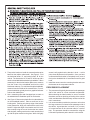
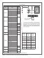
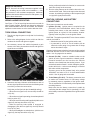
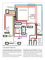
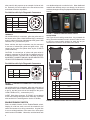
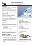
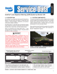
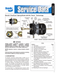
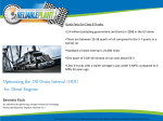
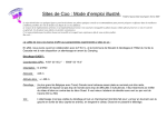
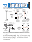
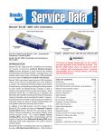
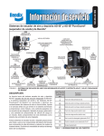
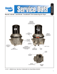
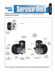
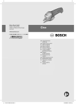
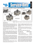
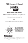
Installation Instructions
AutoVue® Lane Departure Warning (LDW) System (3G) by Bendix CVS
PREPARATION
The vehicle must be parked on level ground. Switch off the
ignition and disconnect the battery.
Read and understand this document before beginning work.
See the General Safety Guidelines on Page 2. Familiarize
yourself with the kit contents; kits may feature speakers OR
vibrating seat motors.
A-Pilla
r
A-Pilla
r
Inspect the windshield area where the camera will be
mounted for damage/cracks to be sure there will be a clear
view.
In some cases, it may be necessary to consult the vehicle's
electrical schematic diagram(s) to plan access to the power
supply and the turn-signal wiring.
REQUIRED TOOLS
3¼ inch hole saw; wire strippers; wire crimpers; small
"torpedo"-style level; test light or multimeter; and wire-pulling
aids. Depending on the installation, see a list of optional
tools on the final page.
INSTALLATION OVERVIEW
Plan the entire installation before beginning work. Some
key points to bear in mind when planning the installation are:
•
Camera and processor placement - note that the length
of the camera cord is approximately 22 in. (550 mm)
long.
•
Wiring harness routing.
•
Access to the turn-signal wiring.
•
Dash switch location and wiring.
•
Speaker (or seat motor) locations and wiring.
Where you are installing Autovue® LDW system on multiple
vehicles, standardize the best installation for the model; this
will assist when troubleshooting.
Kit Contents
KeyDescription
Qty
1. Lane Departure Warning processor . . . . . 1
2. Camera with windshield bracket . . . . . . .1
3. Two 3½-inch speakers with covers
(optional) . . . . . . . . . . . . . . . . . . . 2
4. Vibrating seat motors (optional) . . . . . . . .2
5. Enable/Disable switch . . . . . . . . . . . . .1
6. Driver information sticker (not shown) . . . . 1
7. Wiring harness
(16 wire, color-coded; 20 foot) . . . . . . . . 1
8.Connectors . . . . . . . . . . . . . . . . . 14
9. 120 Ohm resistors (not typically needed) . . . 2
10. Other wiring harnesses . . . . . (varies by kit)
7
CAMERA MOUNTING
3
IMPORTANT: Before mounting the camera, verify that the
vehicle is level.
1. Clean and inspect the inside of the windshield where the
windshield bracket will be mounted. Use a denatured
alcohol-based (or similar) cleaner. Cracks/distortion/
damage that would interfere with the camera operation
are not acceptable. Clean and dry the windshield; the
presence of grease or dirt will affect the adhesive used
to hold the camera bracket in place.
2
8
5
1
(Sticker, vibrating seat motors, extra harnesses,
and windshield bracket not shown)
FIGURE 1 - INSTALLATION KIT
1
2. The precise location to install the camera bracket varies
based on the vehicle make/model. See Figure 2. Find
the horizontal offset “A”, and vertical offset “B” for the
vehicle. The intersection of "A" and "B" will line up with a
notch in the windshield bracket during installation. When
measuring for the window bracket placement, measure
from the center of the windshield and from the solid
black area at the top. For vehicles with split-windshields,
measure from the middle of the center divider. For onepiece windshields, typically there is a graphical indicator
to show the middle point.
3. Use a measuring tape and fine-tipped pen to mark on
the windshield the installation point for the bracket.
4. See Figure 2 Remove the plastic film from the adhesive
on the windshield bracket. Place a small level on the
leveling tabs. Touching only the top edge of the bracket
to the glass at first, align your mark with the notch in the
bracket. Adjust the angle of the bracket until it is level,
then carefully bring the rest of the bracket into contact
with the glass, making sure that the notch remains lined
up with the point marked on the glass. While it is lightly
2
seated, verify again that the bracket is level — at this
point some adjustment is still possible. Once you have
confirmed that the bracket is completely level, press it
firmly to the windshield for 10 seconds to ensure a good
bond.
5. Install the camera onto the mounting bracket and route
the harness to the compartment above.
PROCESSOR PLACEMENT
1. The processor will typically be mounted on the passenger
side of the vehicle in a front overhead compartment.
When selecting the ideal location, be sure to consider
that there must be no pinching or binding of the camera
cable, and that there should be easy access to all of the
unit's connections.
2. It is recommended to position the processor unit so that
the large connector is oriented to the passenger side of
the vehicle. A good practice is to leave 12 in. (or more)
of excess harness on the connector side for a service
loop. The processor should be mounted flat, using the
hook-and-loop-fastener pad to attach it to the vehicle.
Top of Windshield
Model
Argosy
1
Cascadia (AM)
8
Cascadia (OEM)
10
Freightliner Cent/Col.
A
Camera
Location
Code
B
Center Line
Make*
Notch in
the Camera
Bracket
1
Classic XL
FL70
2
M2
4300
8100
8600
9200
2
“Torpedo” Level Rests
on the Bracket Tabs
International 9400
9900
Lonestar
Pro Star
Workstar/7000 Series
Kenworth
2
T200
2
T600/800
3
T600/800 Flt Wndshld
7
T660
3
T680
T700
Mack
9
Pinnacle
Vision
2
2
Camera
Location
Code
Horizontal
Offset
Vertical
Offset
“A”
“B”
1
9 ± 0.25 in.
2 ± 0.5 in.
2
6 ± 0.25 in.
2 ± 0.5 in.
3
9 ± 0.25 in.
3 ± 0.5 in.
7
7 ± 0.25 in.
3 ± 0.5 in.
8
7 ± 0.25 in.
2 ± 0.5 in.
9
9
6 ± 0.25 in.
2.5 ± 0.5 in.
2
10
8 ± 0.25 in.
2 ± 0.5 in.
378
379
385
386
389
Peterbilt
340 Car Hauler
To determine the correct point on the windshield to
line up to the notch in the camera bracket, use the
Make/Model columns of the table (left) to find the
Camera Location Code. The second table (below)
shows the correct vertical and horizontal offset to
use for each Code.
2
379 Car Hauler
384/386 with video
384/386 with Curved Windshield
387 (AM)
387 (OEM)
579
Sterling
Volvo
A-Line
A-Line Car Hauler
NonVolvo Engine
Volvo Engine
Western Star 4900
2
2
* All trade marks shown here are the property of their respective owners and are used for reference only.
FIGURE 2 - LOCATING THE CORRECT POINT TO MOUNT THE CAMERA BRACKET
3
Retain All Harnesses
NOTE: Store all the wiring harnesses supplied in the
kit — including any not used in this installation — with
the processor in the overhead compartment. Additional
systems that interact with the Autovue® LDW system, may
require these harnesses.
WIRING HARNESS ROUTING
See Figure 1. The 20 foot wiring harness can be routed via
either, or both, A-pillars. Routing may depend on where the
dash Enable/Disable switch will be located, and whether
speakers or seat-motors are to be used to alert the driver.
TURN SIGNAL CONNECTIONS
1. Test the turn signal system to verify that it is functioning
correctly.
2. Refer to the wiring diagram for the vehicle to find wire
numbers for the left and right turn signals.
3. As necessary, remove the vehicle trim/panels to gain
access to the wiring looms where the left and right turn
signal wires are located.
Having confirmed each wire for function, be sure to mark
each wire clearly for the next step.
5. Run the wiring harness to the location where the connection will be made. Refer to the tags on the wires and
connect, by soldering or splicing, to their respective (left
or right) turn signal positive wires.
IGNITION, GROUND, AND BATTERY
CONNECTIONS
Three power connections must be made:
1. Ignition (Pin A9). Ignition power is required for the
processor, the Enable/Disable switch, and for kits
including seat motors, to the seat connector. Obtain
ignition power at a good 12 Volt accessory location:
typically at the fuse panel; or at the ignition switch.
CAUTION: The Ignition power MUST come from a suitable
vehicle circuit that is:
• Switched on and off by the ignition switch; and,
• Is protected by a fuse or circuit breaker with an
electrical current rating of no greater than 15 Amps
and no less than 5 Amps.
Connect Ignition power to both the harness red wire marked
IGNITION, and also to Pins 10 and 12 the Enable/Disable
switch. Use 18 gauge wire as needed.
2. Ground (Pin B9). Locate a suitable location on the
vehicle to make a good connection to chassis ground.
Potential locations are: the fuse box; the vehicle's
chassis; or the firewall near the steering column. If you
select the chassis or firewall — and in making the ground,
need to drill a hole — take care not damage, or interfere
with other vehicle components.
• Connect ground to the harness black wire marked
GROUND, and also to Pin 2 of the Enable/Disable
switch. Use 18 gauge wire as needed.
FIGURE 3 - LOCATING THE TURN SIGNAL POSITIVE WIRES
4. Connect a test lamp, Voltmeter or Multimeter to each of
the turn signal positive wires and use the following tests
to confirm you have the correct wires.
Verify that you find (for both the left and right wiring):
• When the turn signal is off, the test lamp should be
off (or 0v);
• When the turn signal is operating, the test lamp should
blink (or pulse 12v);
• When the service brake pedal is applied (with the turn
signal off), the lamp should be off (or 0v);
• When the parking brake pedal is engaged or
disengaged, (with the turn signal off), the lamp should
be off (or 0v); and
• When the headlights are switched on, (with the turn
signal off), the lamp should be off (or 0v).
4
3. To the Battery (Pin A11). The battery connection must
be made at a location where 12 Volt battery voltage
is constantly present, regardless of the ignition state.
This is essential for full functionality of the optional data
recording features.
Make sure that the battery connection is stable by
confirming that the voltage level is (nominally) 12 Volts
at the battery connection regardless of the ignition switch
position.
Right Speaker Positive - Blue
Right Speaker Negative - Blue/white stripe
Right Vibrating Seat Motor - Brown
Left Vibrating Seat Motor - Pink
Speed (Yellow/Black) Not Used
RS232
COMM
DB9
Ground - Black
RS232 RX - Yellow
LDW PROCESSOR
RS232 TX - Orange
Left Speaker Positive - Brown
Left Speaker Negative - Brown/White Stripe
LDW
CAMERA
Warning Enabled Lamp - Blue
Ignition - Red
12 Volt Ignition
Source
12V Battery
Red/Yellow
Stripe
Green LED
10
Ignition - Red
ABC
12 Volt Battery
Source
9
(A, B, and C
are Contact
Designators for
this Connector)
Enable/ Disable Switch - Grey 1
Enable/
Disable
Switch
2
4
Left Speaker
12
11
Ground - Black
J1939 CAN Bus
Amber LED
J1939 Pos
Yellow
Status Lamp Output - Purple
J1939 Neg
Green
Left Turn
Signal
Positive
(Orange)
Right Speaker
Ignition - Red
Chassis
Ground
(White)
Right Turn
Signal
Positive
Left
Seat
Motor
Right
Seat
Motor
NOTE: This wiring
diagram shows
both speaker
and vibrating
seat motor
connections;
actual harnesses
will have only one
or the other.
FIGURE 4 - AUTOVUE® LDW SYSTEM WIRING DIAGRAM
J1939 CAN BUS CONNECTION
The J1939 CAN (Controller Area Network) Bus is a
communications standard designed to permit vehicle devices
to communicate with each other. To enable the full range
of the Autovue® LDW system by Bendix CVS features, the
designated wires in the harness need to be connected to
the J1939 CAN Bus.
Most vehicles have a 6- or 9-pin diagnostic connector, near
the driver-side door, typically low down on — or under —
the dash. See Figures 4 and 5. This connector is used by
PC Diagnostics to examine engine performance data and
Diagnostic Trouble Codes (DTCs), and is an ideal point to
connect the AutoVue LDW system harness.
NOTE: For vehicles built since 2005, the J1939 CAN Bus
is almost always activated. In rare cases where J1939 CAN
Bus is not found, see the Troubleshooting section.
Gain access to the wires behind the connector. A yellow
and green twisted pair of wires is the Standard for J1939
CAN Bus wiring; see the AutoVue LDW system harness
5
wires used for this purpose as an example of what to look
for. Generally, it is best to splice in the new wires as close
to the data connector as possible.
For Vehicles with 9-pin Diagnostic Connectors
Pin
Location
Signal
Description
C
CAN_H
CAN Bus, High
D
CAN_L
CAN Bus, Low
E
CAN_GND
CAN Ground
This is a different CAN Bus DO NOT USE!
H&J
or a dashboard-punch to make the hole. Most dashboard
materials are relatively easy to cut through, but be sure to
avoid any damage to wiring or equipment behind the selected
location.
View Looking Into the Connector
FIGURE 5 - 9-PIN DEUTSCH CONNECTOR: J1939 CAN BUS
TERMINALS
On vehicles with 9-pin connectors, splice the yellow wire of
the harness to the yellow J1939 CAN Bus High (+) connected
to pin C, and the green wire of the harness to the green J1939
CAN Bus Low (-) connected to pin D.
Some vehicles with 9-pin connectors may be connected
to two sets of twisted pair yellow and green wires. Only
connect to the green and yellow wires at pins C AND D
(J1939 CAN Bus).
FIGURE 7 - EXAMPLE ENABLE/DISABLE SWITCH
INSTALLATION
See Figure 8 for the wiring connections. As you attach the
wiring, since the terminals are not in numeric order, be sure
to verify the exact location number for each wire as you
assemble the connector for the back of the switch.
CAUTION: If a second set of yellow and green wires is
presently connected to Pins H and J be aware that this is
a different CAN Bus - DO NOT USE THIS BUS for this kit.
INCORRECT CONNECTION MAY CAUSE UNEXPECTED
VEHICLE PERFORMANCE PROBLEMS.
For Vehicles with 6-pin Diagnostic Connectors
Pin
Location
Signal
Description
D
CAN_H
CAN Bus, High
F
CAN_L
CAN Bus, Low
12 4 3
2
1 10
Terminal
Numbers
9 5 6 7 8 11
View Looking Into
the Connector
Pin
FIGURE 6 - 6-PIN DEUTSCH CONNECTOR: J1939 CAN BUS
TERMINALS
On vehicles with 6-pin connectors, splice the yellow wire of
the harness to the yellow J1939 CAN Bus High (+, connected
to pin D), and the green wire of the harness to the green
J1939 CAN Bus Low (-, connected to pin F).
ALERT: With either connector, IF FOUND, do not attempt
to use sets of orange and green wires; these are J1708 Bus
wires and this kit is not designed to use the J1708 Bus.
ENABLE/DISABLE SWITCH
Select a suitable location for the Enable/Disable switch,
keeping in mind how much room will be needed for the
switch and access to its wiring connections. A typical site
is next to existing switches of the same size; use a spare
switch location if available. Otherwise, use hand tools and/
6
Color
Description
1
Grey
AutoVue Harness, Also Connects to Pin 4
2
Black
Ground
4
Grey
AutoVue Harness, Also Connects to Pin 1
9
Blue
Warning Lamp Enabled
10
Red
Ignition, Also Connects to Pin 12
11
Purple
Status Lamp Output
12
Red
Ignition, Also Connects to Pin 10
®
FIGURE 8 - ENABLE/DISABLE SWITCH CONNECTIONS
DRIVER ALERT SYSTEMS - AUDIBLE OR
VIBRATION
VIBRATING SEAT MOTOR ALERT SYSTEM
Kits will either contain a speaker-based alert system, or use
vibrating seat motors in the driver's seat to provide feedback.
AUDIBLE ALERT SYSTEM
The standard location to install the speakers is above and/
or close behind, the head of the driver (and passenger).
Check that the location selected has both room behind the
panel for the speakers to fit, and in front for the speaker
grills. A 3¼ inch hole saw can be used to cut the holes for
the speakers. Select the correct set of speaker wires and
pull each pair of wires to the respective side, through the
hole into the cab.
Harness Speaker Wire Color
Where Used
Brown / Brown and White
Left (Driver Side)
Dark Blue / Dark Blue and White
Right (Passenger Side)
Use the terminals supplied, or use solder, to connect the
speakers to the harness. Install the u-nuts at the sides of
the holes cut. With the speaker and grill aligned, install the
screws supplied. See the speaker image in Figure 9.
When the installation is complete, at vehicle start-up, the
speakers will "chirp" in sequence (left then right) to confirm
that they are functioning.
See Figure 9 (NOTE: The exact kit components may vary
from the items shown.)
Instead of speakers, selected kits use vibrating seat motors
to signal to the driver. For these kits, route the pink and
brown harness wires to the floor at the back of the seat. The
red wire that comes already installed to the smaller section
of the connector needs to be run back to the ignition power
(see the Ignition, Ground, and Battery Connections section.)
Remove the bottom seat cushion from the driver's seat and
take the cover off to reveal the foam. The motors will be
installed so that they are under the driver's thighs. Plan
the locations and then cut the foam as shown in Figure 9,
including a center pocket for the vibrating seat motor
assembly. As shown, leave a flap of foam to cover the motor.
Run the wires from the motors to the back of the seat by
cutting a slit part-way into the foam and routing the wires
through it.
A connector with two detachable halves is used to join the
motor harnesses and the wiring from the system and ignition.
Before cutting any excess from the wires, plan the location
of the connector, making sure that there will be sufficient
slack to allow the seat to move freely through its full range of
motion. Verify also that the wiring will not be pinched when
the seat is moved.
Typical
Speaker
Location
Kit Harness Featuring
Vibrating Seat Motors
Preparing and Installing the
Vibrating Seat Motors:
Routing the Wiring
Preparing and
Installing the Seat
Connector Wiring
Using the Delphi
PED connector
Black
Red
(Combined)
Black
FIGURE 9 - DRIVER ALERT SYSTEMS
Pink
Red
(Factory
Installed)
Brown
7
Connections from the Vibrating Seat Motor Side
Using Delphi connectors, install the vibrating seat motor
wires into the smaller section of the connector. The black
wire from the right motor goes into slot C, the black wire from
the left motor goes into slot A, and the two red wires from the
motors are joined together and go into slot B of the Delphi
connector that is supplied with the kit.
The seat cushion can now be replaced. Use wire loom
protectors for any exposed wiring.
Connections From the Harness Side
This connector supplied has a red wire already installed
into slot B; this wire must connect to a good 12 Volt ignition
source protected by a fuse or circuit breaker with a current
rating between 5 (five) and 15 Amps.
Using Delphi connectors, install the pink wire into slot A and
the brown wire into slot C. The pink wire is used to control
the left vibrating seat motor and the brown wire controls
the right motor by supplying the motor with a ground. Join
the two halves of the connector together. Use wire loom
protectors for any exposed wiring.
FINAL STEPS AND SYSTEM TESTING
Install the Driver Information Sticker in a suitable location on
the vehicle, visible to the driver.
Return all vehicle panels and wiring looms to their installed
positions.
Restore the battery connections.
When the vehicle power is switched on the Autovue® LDW
system by Bendix CVS will go through a self test:
• If equipped with speakers, you will hear a chirp from the
left and right speakers respectively, in that order.
• If equipped with vibrating seat motors, you will feel a
short pulse from the left and right motors respectively,
in that order.
Both the green and yellow indicator lights on the Enable/
Disable switch should remain on. Both the green and yellow
lights should remain on until you reach 38 to 40 mph (61 to
64 km/h), at which point the system is active.
Test drive the vehicle (both day and night where practical).
8
Enable/Disable Switch Lamp Behavior:
Warning
Enabled
Lamp
(Green)
Status
Lamp
(Yellow)
Warnings
Ready
Vehicle Speed
< 37 mph
(60 km/h)
ON
ON
No
Can’t Find Lane
Markings
ON
ON
No
Vehicle Speed
> 37 mph
(60 km/h) AND
Lane Markings
Found
ON
OFF
Yes
Driver Presses
Switch to
Disable
Warnings
OFF
OFF
No
System
Diagnostic
Trouble Code
(DTC) Set
OFF
ON
No
Situation
TROUBLESHOOTING:
At start-up, if the green light on the Enable/Disable switch
illuminates and then goes out after a few seconds, this
typically indicates that the system is not finding the J1939
CAN Bus data link. If so, test the following:
1. Check for loose connections to the data link wiring.
2. Use PC diagnostics to check the J1939 CAN Bus.
Two much more rare possibilities are:
3. The J1939 CAN Bus is not activated. Typically the J1939
CAN Bus can be activated via the engine diagnostic port
using a laptop, or diagnostic computer.
4. The vehicle does not have the J1939 Bus wiring run
from the engine ECM connector or Vehicle Control
Unit. Consult the OEM documentation for the correct
procedure to permit J1939 communications. Where this
is necessary, the two 120 Ohm resistors are supplied in
the kit to be used— if necessary — to assist with obtaining
the 60 Ohms required across the yellow and green wires,
so that the ECM recognizes that the J1939 Bus is in use.
Status Lamp (Yellow)
RESERVED
Speed (NOT USED)
RESERVED
Ignition
Left Turn Signal
RS-232 TX
Left Seat Vibrating Seat Motor (Optional)
12V Battery
Right Speaker (+) (Optional)
J1939 High
Left Speaker (+) (Optional)
J1939 Low
Left Speaker (-) (Optional)
RS-232 RX
Right Speaker (-) (Optional)
RESERVED
Right Vibrating Seat Motor (Optional)
Vehicle Ground
Right Turn Signal
Enable/Disable Switch
RESERVED
Warning Enabled Lamp (Green)
RESERVED
Connector Diagram (viewed from wiring side of harness connector):
RESERVED = Reserved for future use.
Pin
Term
Input/
Output
Wire Color
Connection
Function
A1
Left Speaker (+)
(Optional)
O
Brown
8 Ohm, 25 W speaker
(between A1 and B1)
Generates audio warning during left side lane
departure.
A2
Right Speaker (+)
(Optional)
O
Blue
8 Ohm, 25 W speaker
(between A2 and B2)
Generates audio warning during right side lane
departure.
A3
Left Vibrating Seat
Motor (Optional)
O
Pink
Vibrating seat motor (+) lead
Generates seat signal during left side lane departure.
A4
Left Turn Signal
I
Orange
Vehicle left turn signal line
Disable all warnings when turned on.
A7
Status Lamp
(Yellow)
O
Purple
Low side of yellow LED
Indicates to driver that the system is not ready to
give warnings.
A9
Ignition Voltage
I
Red
Vehicle ignition switch
Provides system power.
Used for communication with other computer
devices.
A10
RS-232 TX
O
Orange
Connects to RS-232 port,
data receive input
A11
Battery Voltage
I
Red/Yellow
Vehicle battery feed
Allows unit to store data during power down
sequence after ignition has been turned off.
A12
J1939 High
I/O
Yellow
Vehicle J1939 Bus (high side)
CAN Bus; Source of vehicle speed.
B1
Left Speaker (-)
(Optional)
O
Brown/White
Stripe
8 Ohm, 25 W speaker
(between A1 and B1)
Generates audio warning during left side lane
departure.
B2
Right Speaker (-)
(Optional)
O
Blue/White
Stripe
8 Ohm, 25 W speaker
(between A2 and B2)
Generates audio warning during right side lane
departure.
B3
Right Vibrating Seat
Motor (Optional)
O
Brown
Vibrating seat motor (+) lead
Generates seat signal during right side lane
departure.
B4
Right Turn Signal
I
White
Vehicle right turn signal line
Disable all warnings when turned on.
B7
System Enabled
Lamp (Green)
O
Blue
Low side of green LED
Indicates to driver that system is enabled.
B8
Enable/Disable
Switch
I
Grey
Normally open, momentary switch
connected to chassis ground
Allows the driver to temporarily disable warnings in
confusing situations (e.g. construction zones with
multiple sets of lane markings.)
B9
Vehicle Ground
I
Black
Vehicle chassis ground
System power return.
Used for communication with other computer
devices.
CAN Bus; Source of vehicle speed.
B11
RS-232 RX
I
Yellow
Connects to RS-232 port,
data transmit output
B12
J1939 Low
I/O
Green
Vehicle J1939 Bus (low side)
FIGURE 10 - WIRING REFERENCE CHART
9
NOTES
10
NOTES
11
Bendix Technical Assistance Team
For direct telephone technical support, call the Bendix Tech Team at:
1-800-AIR-BRAKE (1-800-247-2725). Tech Team members are
available Monday through Friday, 8:00 A.M. to 6:00 P.M. ET.
Or, if you prefer, e-mail us at: [email protected]. Please
have the following information ready when you contact the Bendix
Tech Team: Bendix product model number; part number and
configuration; vehicle make and model.
Tools
Some installers have found the following items useful:
• Delphi Crimper (part number 06285847) for switch contacts.
• Panel Punch (part number DIN-132) for making the hole for the
Enable/Disable switch. (www.panelpunches.com)
Miscellaneous Supplies
• Wire Loom Protectors (for the vibrating seat motor installation.)
S-1580 © 2013 Bendix Commercial Vehicle Systems LLC, a member of the Knorr-Bremse Group. 7/13. All Rights Reserved.
12