1
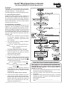
Bendix Wheel Speed Sensor Checklist
®
(See Document BW1922 for Full Bendix Warranty Policy)
Preparation
CAUTION: Follow all standard safety precautions
- see back page. Park the vehicle, chock the wheels
and drain air system. Turn the ignition off.
Use ABS diagnostics to find the suspected sensor.
A. Inspect Physical Condition
Inspect the sensor cable for cuts, evidence of
pinching or wear, abrasions with wiring exposed. If
any of the above conditions are noted, replace the
sensor, clear the trouble code according to the ECU
Service Data directions. Re-check system before
returning vehicle to service.
B. Test Resistance and Voltage
The vehicle must be at ambient temperature (0-100
degrees F, -18 to 38 degrees C) for an accurate
reading, so be sure that the wheel end area is not hot.
Based on the ABS ECU diagnostic code, disconnect
the suspected sensor harness. At the extreme top
of the temperature range, the sensor resistance can
vary from 1200-2700 Ohms and still be within the
operable range.
1. Inspect the connectors and terminals
for corrosion, physical damage or loose
connections. If possible, repair and/or clean
the connectors.
2. Use a Volt-Ohm meter to measure resistance
across the connector pins:
check
one
1200-2700
OK - between 1200 and 2700 ohms.
Not OK - less than 1200 or more
than 2700 ohms.
If not OK, replace the sensor. End test.
3. Confirm that chocks are in place on vehicle.
Raise the wheel off the ground to test the
suspect wheel speed sensor.
4. Release the parking brakes.
5. By hand, slowly rotate the wheel at a rate of
at least ½ revolution per second Using an AC
voltage meter, measure the voltage at the ECU
across the sensor terminals.
OK - Output voltage is 0.25 Volt AC
minimum
check
one
Not OK - Output voltage is less than
0.25 Volt AC.
If voltage is not OK, reposition sensor by
gently pushing it closer toward the wheel until
it touches the exciter ring. Repeat the voltage
measurement.
If still not OK, replace sensor. End test.
6. If the Ohm and voltage readings are OK, the
sensor itself is not the cause of the failure.
Reconnect the sensor and examine the wiring
harness and ECU connector for causes of
failure, such as pinched wires, loose pins,
abrasions, exposed wires etc.
BW2453 ©2008 Bendix Commercial Vehicle Systems LLC. 8/08. All Rights Reserved. Printed in USA.
* WHEN REPLACING A SENSOR UNDER WARRANTY
NOTE: DO NOT CUT THE SENSOR CABLE WHEN REMOVING
THE SENSOR so that a proper analysis can be completed
by Bendix Warranty Engineers. Cut or frayed cables are
ineligible for warranty.
A. Use the new corresponding Bendix sensor service kit that
contains the sensor and clamping sleeve.
B. Clear the trouble code using the ECU Service Data
instructions.
C. Include this checklist when returning a sensor. It will help
expedite your claim. Please fill out all applicable fields on
this checklist and include:
ECU Model ________________________
VIN # _________________________________________
SAFE MAINTENANCE PRACTICES
When working on or around a vehicle, the following general precautions should be observed
at all times.
1. Park the vehicle on a level surface, apply the parking brakes, and always block the
wheels. Always wear safety glasses.
2. Stop the engine and remove ignition key when working under or around the vehicle.
When working in the engine compartment, the engine should be shut off and the ignition
key should be removed. Where circumstances require that the engine be in operation,
EXTREME CAUTION should be used to prevent personal injury resulting from contact
with moving, rotating, leaking, heated or electrically charged components.
3. Do not attempt to install, remove, disassemble or assemble a component until you
have read and thoroughly understand the recommended procedures. Use only the
proper tools and observe all precautions pertaining to use of those tools.
4. If the work is being performed on the vehicle’s air brake system, or any auxiliary
pressurized air systems, make certain to drain the air pressure from all reservoirs
before beginning ANY work on the vehicle. If the vehicle is equipped with an AD-IS®
air dryer system or a dryer reservoir module, be sure to drain the purge reservoir.
5. Following the vehicle manufacturer’s recommended procedures, deactivate the electrical
system in a manner that safely removes all electrical power from the vehicle.
6. Never exceed manufacturer’s recommended pressures.
7. Never connect or disconnect a hose or line containing pressure; it may whip. Never
remove a component or plug unless you are certain all system pressure has been
depleted.
8. Use only genuine Bendix® replacement parts, components and kits. Replacement
hardware, tubing, hose, fittings, etc. must be of equivalent size, type and strength as
original equipment and be designed specifically for such applications and systems.
9. Components with stripped threads or damaged parts should be replaced rather than
repaired. Do not attempt repairs requiring machining or welding unless specifically
stated and approved by the vehicle and component manufacturer.
10. Prior to returning the vehicle to service, make certain all components and systems are
restored to their proper operating condition.
11. For vehicles with Antilock Traction Control (ATC), the ATC function must be disabled
(ATC indicator lamp should be ON) prior to performing any vehicle maintenance where
one or more wheels on a drive axle are lifted off the ground and moving.
___________________
Reference Documents:
Service Data Sheet: Bendix® WS-24™ AntiLock Wheel Speed Sensor . . . . . SD-13-4860 (BW2364)
Bendix ABS Warranty Policy. . . . . . . . . . . . . . . . . . . . . . . . . . . . . . . . . . . . BW1922
ACom™ Diagnostics PC Software . . . . . . . . . . . . . . . . . . . . . . . . . . . . . . . . . BW2329
(Free downloads available on www.bendix.com)
ABS Repair and Diagnostics DVD . . . . . . . . . . . . . . . . . . . . . . . . . . . . . . . . BW2538
Visit the Literature Center on www.bendix.com for free downloads of Service Data Sheets and Warranty Policies or
to order copies.
For more information, contact your local Bendix representative or the Bendix Technical Assistance Team at
1-800-AIR-BRAKE (1-800-247-2725), Monday through Friday, 8:00 A.M. to 6:00 P.M. EST, and follow the instructions
in the recorded message. Or, you may e-mail the Bendix technical assistance team at: [email protected].
BW2453 ©2008 Bendix Commercial Vehicle Systems LLC. 8/08. All Rights Reserved. Printed in USA.