1
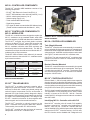
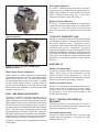
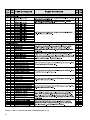
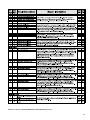
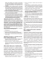
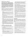
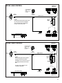
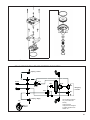
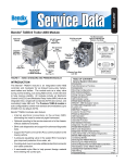
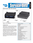
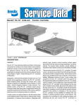
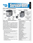
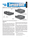
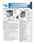
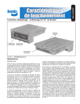
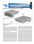
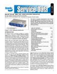
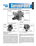
SD-13-4834
Bendix® MC-30™ Trailer ABS Controller Assembly
LED Diagnostic
Display
ABS Modulator
Connector
(MOD1)
Delivery Ports
3/8" NPT (x4)
TABLE OF CONTENTS
PAGE
Components . . . . . . . . . . . . . . . . . . . . . . .2
MC-30™ Controller Comparison to MC-12™ Modulator. .2
MC-30™ Controller Assemblies. . . . . . . . . . . . . .2
MC-30™ Controller with PLC . . . . . . . . . . . . . . .2
Wiring Harness (Pigtail) . . . . . . . . . . . . . . . . .3
Power and Ground . . . . . . . . . . . . . . . . . . . .5
ABS Indicator Lamp . . . . . . . . . . . . . . . . . . .5
Wheel Speed Sensors . . . . . . . . . . . . . . . . . .5
M-30T™ ABS Modulator-Valves . . . . . . . . . . . . .6
J1708/J1587 Diagnostic Link . . . . . . . . . . . . . .6
Auxiliary I/O . . . . . . . . . . . . . . . . . . . . . . .6
MC-30™ Controller Power-up Sequence . . . . . . . . .7
ABS Operation . . . . . . . . . . . . . . . . . . . . . .7
Self-Configuration/Control Toggle . . . . . . . . . . . .8
Other Configurable Parameters . . . . . . . . . . . . 11
Odometer Function. . . . . . . . . . . . . . . . . . . 11
Fault Detection . . . . . . . . . . . . . . . . . . . . . 11
MC-30™ Controller Diagnostic Display . . . . . . . . . 12
Blink Code Diagnostics . . . . . . . . . . . . . . . . 13
Bendix ABS Diagnostic Tools . . . . . . . . . . . . . 16
Contacting Bendix . . . . . . . . . . . . . . . . . . . 16
Correct Maintenance Practices . . . . . . . . . . . . 16
Servicing the MC-30™ Controller . . . . . . . . . . . . 17
Replacing the EC-30T™ Controller . . . . . . . . . . . 17
Overhaul of the Relay Valve . . . . . . . . . . . . . . 17
MC-12™ Modulator / MCE-12 Service-Replacement . . 17
Reinstallation of the MC-30™ Controller or
M-30T™ Modulator-Valve . . . . . . . . . . . . . . . . 18
Leakage and Operational Tests . . . . . . . . . . . . 18
ABS Wiring . . . . . . . . . . . . . . . . . . . . . . . 18
Troubleshooting Flowcharts . . . . . . . . . . . . . . 24
Product Revision / Feature Introduction . . . . . . . . 32
30-Pin
Connector
Control
Port
1/4" NPT
Supply Port
1/2" NPT
FIGURE 1 - MC-30™ CONTROLLER TANK (NIPPLE)
MOUNT ASSEMBLY
MC-30™ CONTROLLER INTRODUCTION
The MC-30™ controller is the Bendix antilock braking system
(ABS) controller assembly intended for application on air
braked heavy duty trailers, semi-trailers and dollies.
The Bendix® MC-30™ controller features an integral LED
diagnostic display with magnetic reset for easy diagnostics
and fault code clearing. Blink code diagnostics are standard
and advanced diagnostic tool support is also available.
The MC-30™ controller supports PLC communication
for indicator lamp, full diagnostics capability and other
customized features.
The ABS function of the MC-30™ controller is designed to
provide a towed vehicle with improved stability and control
during braking while providing the maximum available
braking force.
For updates to this Service Data Sheet, please visit www.bendix.com.
1
MC-30™ CONTROLLER COMPONENTS
The MC-30™ controller ABS installation consists of the
following components:
- EC-30T™ ABS Electronic Control Unit (ECU) (1)
- M-30T™ ABS modulator-valve with relay function (1 or 2)
- WS-20™ wheel speed sensors (2 or 4)
- Sensors spring clips (2 or 4)
- Trailer mounted ABS indicator lamp
- Pigtail wiring harness
- PLC signal for dash mounted trailer ABS indicator lamp
(Towed vehicles manufactured after March 1, 2001)
MC-30™ CONTROLLER COMPARISON TO
MC-12™ MODULATOR
The MC-30™ controller has been designed to replace the
MC-12™ modulator as the standard Bendix trailer ABS
controller assembly for OEM and aftermarket installations.
The EC-30T™ controller has a black plastic enclosure
similar to the Bendix® EC-30™ tractor ABS controller, and
is mounted to the modulator-valve with a bracket. The
MC-12™ modulator utilized a metal ECU enclosure and
was directly bolted to the modulator body. The MC-30™
controller has a 30-pin electrical connector and the MC-12™
modulator has a 14-pin connector.
The M-30T™ ABS modulator-valve utilizes a 3-pin external
electrical connector, where the MC-12™ modulator used a
4-pin internal connector.
Physical
Feature
MC-30™
Controller
MC-12™
Modulator
ECU Enclosure
ECU Mounting
Plastic ECU
Bracket Mounted to
ABS Modulator Valve
30-pin
Metal ECU
Directly Mounted to ABS
Modulator Valve Body
14-pin
3-pin External
Connector
4-pin Internal
Connector
ECU Electrical
Connector
ABS Modulator
Connector
FIGURE 2 - MC-30™ CONTROLLER BRACKET (FRAME)
MOUNT ASSEMBLY
MC-30™ CONTROLLER ASSEMBLIES
Tank (Nipple) Mounted
The MC-30™ controller tank-mount assembly is mounted by
using a schedule 80 (heavy gauge steel) 1/2" nipple directly
between the trailer supply tank and the MC-30™ modulatorvalve supply port. A tank with a reinforced port must be used.
See Figure 1 for tank-mount MC-30™ modulator-valve.
CAUTION: The tank-mounted MC-30™ modulator-valve
cannot be mounted on a frame or crossmember using the
ECU bracket holes.
Bracket (Chassis) Mounted
The MC-30™ controller bracket mount assembly is mounted
directly to the trailer frame rail or crossmember. See Figure
2 for bracket mount MC-30™ controller. The bracket studs
are secured using three 5/16-18 nuts and lock washers
torqued to 180-220 in-lbs.
CHART 1 - MC-30™ CONTROLLER AND MC-12™
MODULATOR DIFFERENCES
MC-30™ CONTROLLER WITH PLC
EC-30T™ TRAILER ABS ECU
Effective March 1, 2001 all towed vehicles must transmit a
signal to control an in-cab trailer ABS indicator lamp. Trailers
built after this date will transmit the status of the trailer ABS unit
over the ignition power wire (blue wire of the J560 connector)
using Power Line Carrier (PLC) communications.
The EC-30T™ is a plastic electronic controller with a
single 30-pin electrical connector. The EC-30T™ controller
enclosure is filled with a hard epoxy-based potting that
seals all internal components from the environment. A
patented LED (light emitting diode) diagnostic display
and magnetic reset switch are incorporated in the housing
for simple, self-contained diagnostics. The design of the
EC-30T™ controller’s electronics is robust against radio,
electromagnetic and environmental interference.
™
The EC-30T controller is typically mounted to the
M-30T™ modulator-valve using four bolts and a bracket.
This assembly forms an MC-30™ ABS controller.
The EC-30T™ controller can also be frame rail mounted,
independent of the M-30T™ modulator-valve.
2
The PLC signal is usually broadcast by the trailer ABS ECU.
The application of PLC technology for the heavy vehicle
industry is known as PLC4Trucks. MC-30™ controller
models with PLC will support communication in accordance
with SAE J2497.
Identifying MC-30™ Controller units with PLC
Most MC-30™ controller units will contain PLC capability.
However, some MC-30™ controller units installed prior to
March 1, 2001 may not. An MC-30™ controller with PLC
can be identified by the individual part number label and pin
stamp on the EC-30T™ controller housing. On PLC units,
the PLC function can be disabled with a diagnostic tool.
This will be the case when an MC-30™ controller is installed
on a powered vehicle auxiliary axle.
Identifying / Measuring the PLC Signal
An MC-30™ controller with PLC will continuously broadcast
PLC messages that indicate trailer ABS status. At powerup or during a trailer ABS fault condition, the MC-30™
controller will signal the tractor ABS unit to illuminate the
dash mounted trailer ABS indicator lamp.
Diagnostic tools are available that detect the presence
of a PLC signal and perform further system diagnostics
directly on the power line. For more information on these
diagnostic tools, contact Bendix or refer to your local
authorized Bendix dealer.
An oscilloscope can also be used to verify the presence
and strength of a PLC signal on the power line. The PLC
signal is an amplitude and frequency modulated signal.
Depending on the load on the power line, the amplitude of
the PLC signal can range from 5.0 mV p-p to 7.0 V p-p.
Suggested oscilloscope settings are (AC coupling, 1 volt/
div, 100 µsec/div). The signal should be measured on
pin 7 of the J560 connector at the nose of the trailer. See
Figure 3 and Figure 4 for examples of PLC measurements
using an oscilloscope.
All connector leads of the MC-30™ controller pigtail harness
are weather sealed at the connector interface and are
clearly labeled for proper installation.
Non over-molded versions of the MC-30™ controller pigtail,
shown in Figure 5, are repairable. If repairs are needed,
see chart 12 for connector and tool information.
Over-molded versions of the wiring harness must be
replaced if corrosion or damage occurs.
ECU Connector
The 30-pin ECU connector of the pigtail is fastened to the
EC-30T™ controller with a jackscrew tightened to 15-20
in. lbs. Improper tightening of the connector jackscrew
can cause environmental contamination or damage to the
EC-30T™ controller. The use of a inch-pound torque wrench
is recommended.
Power / ABS Indicator Lamp Connector
The MC-30™ controller pigtail utilizes the TTMA RP 97-99
5-pin Packard Weather Pack connector for brake light
power, constant power, ground and the trailer mounted ABS
indicator lamp. The Power/ABS Indicator Lamp lead of
the pigtail harness is available in various lengths to satisfy
installation requirements such as slider axles.
Wheel Speed Sensor Connectors
Two or four wheel speed sensor connectors are provided.
These 2-pin connectors are labeled Right Front (RHT FRT),
Left Front (LFT FRT), Right Rear (RHT RER) and Left Rear
(LFT RER). Right Front and Left Front wheel speed sensor
inputs must be used for two sensor installations, even if
the wheel speed sensors are not physically located on the
forward axle. Extension cables are available from Bendix
that will provide longer wheel speed sensor lengths when
required by the installation.
FIGURE 3 - POWER LINE WITHOUT PLC SIGNAL
ABS Modulator Connectors
One or two modulator connectors are provided. These 3-pin
connectors are labeled MOD 1 and MOD 2. Modulator 1
is always used for single modulator installations. For two
modulator configurations, Modulator 1 is installed at the
right or front position. Modulator 2 is installed at the left
or rear position. An extension cable must be used for
Modulator 2. The remote modulator harness is available
in various lengths to satisfy any installation requirement.
See Figure 6.
FIGURE 4 - POWER LINE WITH PLC SIGNAL
Diagnostic Connector
™
MC-30 CONTROLLER WIRING HARNESS
(PIGTAIL)
The EC-30T™ controller utilizes a pigtail wire harness to
interface with ABS and other trailer system components.
Various pigtail harness part numbers are available from
Bendix. The following connectors are optional and may not
be present on all pigtail harnesses: Modulator 2, auxiliary,
diagnostic, and rear axle wheel speed sensors.
An optional 4-pin diagnostic connector provides a port
for connecting a diagnostic tool. The connector provides
ignition power, ground and data lines. Remote diagnostic
cables are available from Bendix that will provide a
standard J1708/J1587 diagnostic port at the side of the
trailer. See Figure 7.
3
Auxiliary I/O Connector
POWER AND GROUND
An optional auxiliary connector provides a connection to
the MC-30™ controller auxiliary feature I/O pins. The five
auxiliary ground-switch inputs and two auxiliary outputs can
be activated and configured with a diagnostic tool.
Trailer electrical power is supplied to the MC-30™ controller
from the ignition and brake light circuits. Note: The MC-30™
controller may not function properly when powered with a
battery charger. See Chart 2.
30-Pin ECU
Connector
ECU Connector Jackscrew
(Tighten to 15-20 in. lbs.)
3-Pin Modulator 2
(MOD2)
8-Pin Auxiliary
(AUX)
3-Pin Modulator 1
(MOD 1)
4-Pin Diagnostic
(DIAG)
Left Rear
(LFT RER)
Right Front
(RHT FRT)
5-Pin Power and
Indicator Lamp
(PWR/WL)
Left Front
(LFT FRT)
Right Rear
(RHT RER)
2-Pin Wheel
Speed Sensors
FIGURE 5 - MC-30™ CONTROLLER PIGTAIL HARNESS (4S/2M WITH DIAGNOSTIC AND AUXILIARY CONNECTORS
SHOWN)
To
Pigtail
Modulator 2
(MOD2)
FIGURE 6 - REMOTE MODULATOR HARNESS (MOD2)
4
To
Pigtail
To Diagnostic
Tool
FIGURE 7 - REMOTE DIAGNOSTIC HARNESS
Circuit
7-Pin Trailer
Electrical
Connector
5-Pin ABS
Power
Connector
30-Pin ECU
Connector
Ignition Power (PLC)
(Blue Wire)
Pin 7
B
Pin E1
Brake Light Power
(Red Wire)
Pin 4
A
Pin E3
Ground
(White Wire)
Pin 1
E
Pin D2
Indicator Lamp
(White/Green Wire)
N/A
D
Pin D3
Function Mode
Value
Operating Range
8.0 to 16.0 VDC
ECU Active
383 mA
ABS Active
(1 modulator)
2.4 A @ 12 VDC
ABS Active
(2 modulators)
4.5 A @ 12 VDC
CHART 2 - POWER AND GROUND
Previous Bendix Wheel Speed Sensors
Previous sensors are all replaced by the
Bendix WS-24™ wheel speed sensor shown below.
90° Speed
Sensors
ABS INDICATOR LAMP
Straight Speed
Sensors
Trailer Mounted Lamp
The MC-30™ controller controls an ABS indicator lamp
to indicate the trailer ABS status. The MC-30™ controller
directly controls the ABS indicator lamp by providing a
12.0 VDC signal to turn it on. The other side of the lamp
is grounded. The MC-30™ controller must be powered in
order to operate the trailer indicator lamp. Pin D3 of the
30-pin connector is the ABS indicator lamp output.
Dash Mounted Lamp (PLC Controlled)
MC-30™ controller models with PLC will transmit a signal to
control a trailer ABS indicator lamp mounted on the dash
of the tractor. MC-30™ controller will transmit the status of
the trailer ABS unit over the ignition power pin E1 of the
30-pin connector. The ignition power wire (blue wire of the
J560 connector) will carry this signal to the towing vehicle.
MC-30™ controller models with PLC support communication
in accordance with SAE J2497.
WHEEL SPEED SENSORS
Wheel speed data is provided to the MC-30™ controller
from the Bendix wheel speed sensors. See Figure 8 for
examples. Working with a tone (exciter) ring, the wheel
speed sensors provide the MC-30™ controller with an AC
signal, which varies in voltage and frequency in relation
to the speed of the wheel. The MC-30™ controller is
configured to receive wheel speed information from 100
tooth tone rings by default. Vehicle axle and ABS control
configurations determine if two or four wheel speed sensors
must be used. See the MC-30™ controller’s electrical
system schematic for wheel speed sensor connector pin
locations, Figure 16.
Previous
clamping
sleeves have
“BW” in a
diamond
WS-24
sensors use
clamping
sleeves with
“BX” in a
swoosh
symbol
PREVIOUS AND NEW CLAMPING SLEEVES
FIGURE 8 - BENDIX WHEEL SPEED SENSORS
Wheel Speed Sensor Clips
The sensor spring clip is designed to firmly hold the wheel
speed sensor in place while also allowing the sensor to
adjust in position as the wheel and hub rotate. Wheel
bearing play and heavily loaded axles will cause sensors
to self-adjust. Proper sensor installation begins by fully
inserting the spring clip into the block, with the retaining
tabs toward the inside of the vehicle. See Figure 9.
CLIP AND SENSOR INSERTION
FIGURE 9
FIGURE 10
5
Tank (Nipple) Mounted
The M-30T™ modulator-valve tank-mount assembly is
mounted by using a schedule 80 (heavy gauge steel) 1/2"
nipple directly between the trailer supply tank and the
M-30T ™ modulator-valve supply port. A tank with a
reinforced port must be used. See Figure 11.
Bracket (Chassis) Mounted
The M-30T™ modulator-valve bracket mount assembly is
mounted directly to the trailer frame rail or crossmember.
See Figure 12. The bracket studs are secured using
three 5/16-18 nuts and lock washers torqued to 180-220
in-lbs.
FIGURE 11 - M-30T™ TANK (NIPPLE) MOUNT
MODULATOR-VALVE
J1708/J1587 DIAGNOSTIC LINK
The MC-30™ controller provides a J1708/J1587 diagnostic
link with data and power to communicate with the vehicle
and various diagnostic tools. Diagnostics, testing,
configuration, data transfer and other functions can be
performed using this link. The MC-30™ controller is
supported by diagnostic tools such as the MPSI Pro-Link®
and Bendix® ABS Diagnostic Software. Ignition power must
be provided to the MC-30™ controller for the diagnostic link
to be active. See the MC-30™ controller electrical system
schematic for J1708/J1587 diagnostic link pin locations,
Figure 16.
FIGURE 12 - M-30T™ BRACKET (FRAME) MOUNT
MODULATOR-VALVE
Wheel Speed Sensor Adjustment
Speed sensors are properly adjusted by gently pushing
(not striking) the sensor into the clip until it makes contact
with the face of the tone ring. The wheel speed sensor
will automatically adjust as the wheel rotates. If rotating
the wheel causes a gap of 0.020 in. or greater, check for
excessive wheel bearing play or tone ring runout. Proper
wheel speed sensor installation is critical to proper ABS
operation. See Figure 10.
M-30T™ ABS MODULATOR-VALVES
The M-30T ™ Bendix ® trailer ABS modulator-valve is
controlled by the EC-30T™ controller to modify driver applied
air pressure to the service brakes during ABS activation. The
ABS modulator-valve is an electro-pneumatic control valve
and is the last valve that air passes through on the way to
the brake chambers. The hold and exhaust solenoids of the
M-30T™ modulator-valve are activated to precisely modify
the brake pressure on command. The EC-30T™ controller is
designed to control one or two modulator-valve assemblies.
See the MC-30™ controller’s electrical system schematic
for ABS modulator connector pin locations, Figure 16.
The M-30T™ modulator-valve is available in two mounting
configurations.
6
AUXILIARY I/O
Auxiliary Function Inputs
The MC-30™ controller offers five auxiliary ground switch
inputs. These inputs can be configured for various
custom functions using a diagnostic tool. See the
MC-30™ controller’s system electrical schematic for auxiliary
function input connector pin locations, Figure 16.
Auxiliary Function Outputs
The MC-30™ controller offers two auxiliary output drivers.
These outputs can be configured for various custom
functions. Pin F1 of the 30-pin connector is the auxiliary
low side output. Pin K2 of the 30-pin connector is the
auxiliary high side output.
MC-30™ CONTROLLER POWER-UP
SEQUENCE
At power-up, the MC-30™ controller performs a series of
self-checks that can assist a technician in determining the
status and configuration of the system.
Trailer ABS Indicator lamp
At power-up without detected faults, the trailer ABS
indicator lamp will illuminate for 2.5 seconds as a bulb
check and then turn off.
If a PLC tractor and PLC trailer are powered at the same
time, the MC-30™ controller will also trigger a bulb check
on the tractor dash using PLC.
Diagnostic LED Display of Configuration
At power-up, the diagnostic LEDs all illuminate, then display
the current configuration for sensors, modulators and ABS
control. See chart 3. After displaying the configuration,
only the green VLT LED will stay on. However, if a fault is
detected, the faulted component will be displayed by the
red diagnostic LEDs.
MC-30™ Controller – LED Power-Up Sequence
At power-up
All LEDs
1st blink displays number of wheel speed sensors
2 Sensors
SEN-FRT
4 Sensors
SEN-RER-FRT
2nd blink displays modulator configuration
1 Modulator (Dolly-Axle control)
MOD
1 Modulator (Axle control)
MOD-FRT
2 Modulators (Axle control)
MOD-RER-FRT
2 Modulators (Side control)
MOD-LFT-RHT
Normal Operation
No Faults
VLT (green) LED illuminated only
Modulator Chuff Test at Power-Up
At power-up, the MC-30™ controller activates a modulator
chuff test. This electrical and pneumatic ABS modulator
test can assist the technician in verifying that the modulator
wiring and installation are correct. With brake pressure
applied, a properly installed modulator will cause five
rapid audible chuffs of air pressure. If two modulators
are installed, the MC-30™ controller activates 5 chuffs at
Modulator 1 (MOD 1) then Modulator 2 (MOD2). The chuff
sequence is then repeated.
If the modulator is wired incorrectly, the modulator will only
produce one chuff, or no chuff at all. If an issue is detected
during the modulator chuff test, compare the modulator
wiring and plumbing to the MC-30™ controller’s electrical
system schematic and make repairs. See Figures 16 and
17.
Sensors
2
2S/1M
X
2S/2M
X
4S/2M
4
Modulators
1
2
X
X
The MC-30™ controller uses wheel speed sensors, ABS
modulator-valves and an ECU to control trailer wheels by
axle or by side. By detecting excessive wheel slip during
braking and adjusting the pressure to each brake chamber,
the MC-30™ controller is able to optimize slip between the
tire and the road surface. The EC-30T™ controller controls
the ABS modulator-valves, similar to a driver pumping the
brakes. However, the MC-30™ controller is able to pump the
brakes on the vehicle with greater speed and accuracy.
Axle Control
MC-30™ controller axle control will utilize a single ABS
modulator-valve to control wheels from both sides of a
given axle or axles. In the case of an unbalanced braking
surface, axle control will control the high coefficient wheel
just under the lock limit. Temporary periods of wheel lock
are permitted on the low coefficient wheel. Axle control
should not be used on 5th wheel dollies or steerable axles.
When braking on even surfaces, an axle-control system
will perform similar to a side control, two modulator system.
Axle control is available in 2S/1M, 2S/2M and 4S/2M
installations.
Dolly-Axle Control (Select Low)
CHART 3 - LED POWER-UP SEQUENCE
System
Configuration
ABS OPERATION
Available
ABS Control Settings
Axle or Dolly-Axle
X
Axle or Side
X
Axle or Side
CHART 4 - MC-30™ CONTROLLER ABS CONFIGURATIONS
MC-30™ controller dolly-axle control will utilize a single
ABS modulator-valve to control wheels from both sides of
a given axle or axles. In the case of an unbalanced braking
surface, dolly-axle control will control the low coefficient
wheel just under the lock limit. Optimal vehicle stability
is achieved by not allowing the high coefficient wheel to
sustain wheel lock. When braking on even surfaces, a dolly
axle control system will perform similar to side control or
axle control system. Dolly axle control is only available in
2S/1M installations.
Steer Axle Option (MOD2 Select Low)
This option causes MOD2 to be Dolly-Axle controlled and
is only active while configured for 4S/2M Axle control. This
configuration option should be set when MOD2 is installed
on a forward or steer axle of a full trailer. Steer Axle option
can be set using a diagnostic tool or by purchasing an
MC-30™ controller unit with this option pre-set.
Side Control
The MC-30™ controller will utilize a single ABS modulatorvalve to control one or more wheels on a given vehicle side.
In the case of an unbalanced braking surface, MC-30™
controller side control will individually control each side just
under the lock limit. Side control is available in 2S/2M and
4S/2M installations.
Normal Braking
During normal braking, the MC-30™ controller functions as
a standard relay valve. As brakes are applied or released
by the driver, the control signal from the tractor foot valve
causes the M-30T™ modulator-valve to apply proportional
pressure to the trailer brake chambers.
7
SELF-CONFIGURATION / CONTROL TOGGLE
Self-Configuration Procedure
When activated with a magnet or diagnostic tool, the
self-configuration feature allows for wheel speed sensor,
modulator and ABS control settings to be altered. This
is generally performed after replacement of an MC-30™
controller. See chart 5.
Verify that the ECU, wheel speed sensor and ABS
modulator connectors are in place and then power the
MC-30™ controller.
CAUTION: An incorrect ABS configuration may cause
a fault indication or degraded ABS performance. All
MC-30™ controller’s service replacement parts are
initially defaulted to 4S/2M side control and may need
to be reconfigured upon installation. Before and after
activating a self-configuration, always determine
the current ABS configuration by monitoring the
diagnostic LEDs at power-up or by activating blink
code diagnostics.
Wheel Speed Sensors
The MC-30™ controller will self-configure for either two
or four wheel speed sensors. If either rear (RER) wheel
speed sensors are detected, four wheel speed sensors
will be selected. If neither rear wheel speed sensors are
detected, the MC-30™ controller will configure for two wheel
speed sensors. The MC-30™ controller will default to two
ABS modulators for any four sensor configuration.
When configured for two wheel speed sensors, Right Front
(RHT FRT) and Left Front (LFT FRT) wheel speed sensor
inputs must be used, even if the wheel speed sensors are
not physically located on the front axle.
Modulators
The EC-30T™ controller will self-configure for either one or
two modulators. The EC-30T™ controller will automatically
configure for two ABS modulators if it detects Modulator 2
(MOD2) and/or either of the rear wheel speed sensors. If
MOD2 is not detected and no rear wheel speed sensors
are detected, the EC-30T™ controller will configure for a
single ABS modulator.
When configured for a single modulator, Modulator 1 (MOD
1) must be used.
ABS Control Toggle
The MC-30™ ABS controller control setting can be toggled
between Control Group A and Control Group B. When
activated, the MC-30™ controller will toggle the ABS control
between (axle control) and (dolly-axle control or side
control). When a self-configuration occurs without an ABS
control toggle, the ABS control group does not change.
See chart 6 and chart 7.
Determine the current ABS configuration by monitoring the
diagnostic LEDs at power-up or by activating blink code
diagnostics.
Hold a magnet on the reset location of the diagnostic
display. All of the LEDs will be on while the magnet is
held in place.
After holding the magnet in place for 20 seconds, the
LEDs will begin to roll and the MC-30™ controller will selfconfigure for the number of detected wheel speed sensors
and modulators. If it is not desired to toggle the ABS
control, remove the magnet.
The MC-30™ controller will then automatically go through
the power-up sequence and display the new configuration
on the diagnostic LEDs. Verify the new ABS configuration
by monitoring the diagnostic LEDs at power-up or by
activating blink code diagnostics.
If an erroneous sensor or modulator combination is
detected during the self-configuration, fault codes are
activated when the MC-30™ controller returns to normal
operating mode.
ABS Control Toggle Procedure
To also toggle the ABS control, continue to hold the magnet
in place while the LEDs are rolling, for an additional 20
seconds (total of 40 seconds). After holding the magnet in
place for 40 seconds, the LEDs will begin to rapidly flash.
At this point the MC-30™ controller will toggle the ABS
control configuration. Remove the magnet.
The MC-30™ controller will then automatically go through
the power-up sequence and display the new configuration
on the diagnostic LEDs. Verify the new ABS configuration
by monitoring the diagnostic LEDs at power-up or by
activating blink code diagnostics.
ABS
Configuration
Control Group A
2S/1M
Axle
Toggle
Dolly-Axle
2S/2M
Axle
Toggle
Side
4S/2M
Axle
Toggle
Side
CHART 6 - ABS CONFIGURATION AND CONTROL TOGGLE
CHART 5 - SELF-CONFIGURATION AND ABS CONTROL TOGGLE ACTIVATION
8
Control Group B
4S/2M Side to 2S/1M Axle
Your trailer has two wheel speed
sensors and one ABS modulator that
is plumbed for axle control.
The MC-30 ™ controller you have
installed is currently configured for
4S/2M side control.
Provide power to the MC-30™ controller
and verify the current configuration
using the LEDs or blink codes.
4S/2M Side
Hold magnet in place for 20
seconds.
The LEDs will begin to roll as the
installed sensors and modulators are
detected.
2S/1M Dolly-Axle
With the LEDs rolling, continue to hold
the magnet in place for an additional
20 seconds. (Total of 40 seconds)
The LEDs begin to flash as the ABS
control toggle activation occurs.
Remove magnet.
2S/1M Axle
Verify the new configuration using
the LEDs or blink codes.
2S/1M Axle to
2S/1M Dolly-Axle
Your dolly or steer axle has two
wheel speed sensors and one ABS
modulator that is plumbed for axle
control.
The MC-30 ™ controller you have
installed is currently configured for
2S/1M axle control.
Provide power to the MC-30™ controller
and verify the current configuration
using the LEDs or blink codes.
2S/1M Axle
Hold magnet in place for 20
seconds.
The LEDs will begin to roll as the
installed sensors and modulators are
detected.
2S/1M Axle
With the LEDs rolling, continue to hold
the magnet in place for an additional
20 seconds. (Total of 40 seconds)
The LEDs begin to flash as the ABS
control toggle activation occurs.
Remove magnet.
2S/1M Dolly-Axle
Verify the new configuration using
the LEDs or blink codes.
CHART 7 - EXAMPLES OF SELF-CONFIGURATION AND ABS CONTROL TOGGLE (1 of 2)
9
4S/2M Axle to 2S/2M Axle
4S/2M Side to
2S/1M Dolly-Axle
Your trailer has two wheel speed
sensors and two ABS modulators
that are plumbed for axle control.
Your trailer has two wheel speed
sensors and two ABS modulators
that are plumbed for side control.
The MC-30 ™ controller you have
installed is currently configured for
4S/2M axle control.
The MC-30 ™ controller you have
installed is currently configured for
4S/2M side control.
Provide power to the MC-30™ controller
and verify the current configuration
using the LEDs or blink codes.
Provide power to the MC-30™ controller
and verify the current configuration
using the LEDs or blink codes.
4S/2M Axle
4S/2M Side
Hold magnet in place for 20
seconds.
The LEDs will begin to roll as the
installed sensors and modulators are
detected.
Remove the magnet.
Hold magnet in place for 20
seconds.
The LEDs will begin to roll as the
installed sensors and modulators are
detected.
Remove the magnet.
2S/2M Axle
2S/1M Dolly-Axle
Stop! You do not need to perform an
ABS control toggle in this case.
Stop! You do not need to perform an
ABS control toggle in this case.
Verify the new configuration using
the LEDs or blink codes.
Verify the new configuration using
the LEDs or blink codes.
CHART 7 - EXAMPLES OF SELF-CONFIGURATION AND ABS CONTROL TOGGLE (2 of 2)
10
OTHER CONFIGURABLE PARAMETERS
The MC-30™ controller has various configurable function
parameters that can be enabled to provide the user with
additional customized features. The default settings for
these parameters are chosen by the vehicle OEM. The
configurable features include serial communications
message broadcasts, alternative lamp control, various I/O
recognition, ABS control settings and others. To ensure
that the replacement unit has the correct default settings,
reference the original part number. These settings can be
altered using a diagnostic tool. For further information,
contact Bendix or refer to your local authorized Bendix
dealer.
The tire rolling radius is defaulted to 500 revs/mile and can
be adjusted from 300 to 700 revolutions per mile. Refer to
the manufacturer’s tire specification for correct settings.
Tone ring tooth count is defaulted to 100 teeth and can be
set to 80, 86, 100 or 120 teeth.
FAULT DETECTION
ODOMETER FUNCTION
The MC-30™ controller contains self testing diagnostic
circuitry that continuously checks for proper operation of
the ABS components and wiring. The MC-30™ controller
controls a trailer mounted indicator lamp to advise the driver
of the status of the system. The MC-30™ controller may
also send the system status to the towing vehicle using
PLC communications.
The MC-30™ controller’s odometer function stores the
accumulated mileage of the vehicle. The mileage will be
calculated using wheel speed sensor information. Every
1.0 mile accumulated during powered operation will be
recorded.
When the MC-30™ controller senses an erroneous system
condition, it stores the fault code in memory, activates the
indicator lamp and disables all or part of the affected ABS
functions. The faulted component is also identified on the
MC-30™ controller diagnostic display.
Mileage will only be recorded while the MC-30™ controller
is powered. If stop light power is the only power source to
the MC-30™ controller, correct accumulated mileage will
not be recorded.
In some instances, the MC-30™ controller will automatically
reset (self-heal) the active fault code when the fault is
corrected. However, repeated occurrences of a given
fault will cause the fault code to latch. Once the fault code
is latched, a manual reset is required. Latching of faults
assists the technician in troubleshooting intermittent faults.
The fault code is stored in the MC-30™ controller’s memory,
even when power is removed.
The odometer will store vehicle mileage up to 9,999,999
miles. When the odometer mileage counter function is
full, it will latch and not record or calculate any additional
mileage.
The odometer mileage can be read using a diagnostic
tool or blink code diagnostics. Refer to the Blink Code
Diagnostics section for further information.
The odometer mileage can be cleared or reset using a
diagnostic tool. This function is password protected.
After repair, latched fault codes can be reset by briefly
holding a magnet on the reset location of the MC-30™
controller’s diagnostic display. Fault codes can also be
reset with blink code diagnostics or with a diagnostic
tool.
It is necessary to properly configure wheel rolling radius
and tone ring tooth count for accurate odometer mileage
to be accumulated.
When a fault self-heals or is manually reset, the fault code
remains in fault history. Fault history can be retrieved with
blink code diagnostics or with a diagnostic tool.
Calibration of Non-Standard Wheel Sizes
The MC-30™ controller allows for tire rolling radius and tone
ring tooth count parameters to be set for each axle using a
diagnostic tool. These adjustments may be necessary for
the MC-30™ controller to accurately calculate the vehicle
velocity and odometer mileage. Wheels of the same axle
must be set to the same rolling radius and tone ring tooth
count.
In most cases, these parameters are set by the trailer OEM
and do not need to be adjusted. In the case of a service
replacement unit, these parameters will need to be adjusted
if the default settings do not match the vehicle.
Parameter
Rolling
Radius
Tone Ring
Tooth Count
Default Settings
Available Settings
500 revs/mile
300 to 700 revs/mile
100 teeth
80, 86, 100, 120 teeth
MC-30™ Controller ABS Partial Shutdown
Depending which fault is detected, the ABS function may
be completely or partially disabled. Even with the ABS
indicator lamp on, dual modulator configurations may still
provide some level of ABS function on wheels that are not
affected by the fault. Single modulator configurations are
completely disabled for any single fault.
ECU Fault
All functions are completely disabled. The system reverts
to normal braking.
Voltage Fault
While voltage is out of range, ABS function is disabled. The
system reverts to normal braking. When the correct voltage
level is restored, full ABS function is available. Operating
voltage range is 8.0 to 16.0 VDC.
CHART 8 - WHEEL SIZE CALIBRATION FACTORS
11
MC-30™ CONTROLLER DIAGNOSTIC DISPLAY
The MC-30™ controller diagnostic display consists of seven
red fault LEDs, one green power LED and an internal
magnetic reset switch. See Figure 13 for illustration.
No diagnostic tools are needed to read the MC-30 ™
controller’s diagnostic display. A fault displayed on the
LEDs will always cause the ABS indicator lamp to be on.
Reading a Fault
When a fault is detected, the MC-30™ controller identifies
the faulted component with the diagnostic LEDs. A wheel
speed sensor or modulator LED (SEN or MOD) may be
accompanied by wheel location LEDs. An example is
FRT-RHT-SEN. When these three LEDs are on, this is
an indication of a fault on the front axle (FRT), right side
(RHT), wheel speed sensor (SEN).
For complete explanation and troubleshooting of faults
displayed by the LEDs, go to section E, Troubleshooting.
The red diagnostic LEDs only indicate active system faults.
When a fault self-heals or is manually reset, the LEDs are
cleared but the fault code remains in fault history. Fault
history can be retrieved with blink code diagnostics or with
a diagnostic tool.
If faults occur on multiple components, the diagnostic
LEDs will display one fault at a time. When the first fault is
repaired and the MC-30™ controller is reset, the next fault
will be displayed on the LEDs.
Fault Reset
After the fault is corrected, the active fault code and LEDs
can be reset by briefly holding a magnet in place at the
RESET location of the diagnostic display. See Figure
13. All of the LEDs will be on while the magnet is held in
place. If one or more of the LEDs do not go on when the
magnet is in place, replace the EC-30T™ controller. When
the magnet is removed from the reset location, only the
green VLT diagnostic LED should be on. However, if any
red LEDs are still on, active faults are still present in the
system.
Note: A self-configuration will occur if the magnet is held
at the reset location for greater than 20 seconds. Do not
hold the magnet at the reset location for longer than 10
seconds unless a self-configuration is desired.
FIGURE 14 - MC-30™ CONTROLLER LED DIAGNOSTIC
DISPLAY
BLINK CODE DIAGNOSTICS
The MC-30™ controller provides diagnostic and configuration
functions through blink code diagnostics. Blink code
diagnostics are activated by providing constant power to
the ignition circuit and toggling the brake light power input
to the MC-30™ controller.
When blink code mode is activated, the MC-30™ controller
will blink the trailer mounted ABS indicator lamp to display
active fault codes, fault code history, ABS configurations
and odometer mileage. Blink code diagnostics can also be
used to reset active fault codes. See chart 9 for all blink
code functions.
Following a single display of all available messages, the
ABS indicator lamp will remain on for five seconds and
then return to normal operating mode.
FIGURE 13 - MC-30™ CONTROLLER LED DIAGNOSTIC DISPLAY
12
It may be necessary to wait until after the modulator chuff
test before activating brake light power. If wheel speeds are
detected during blink code diagnostics mode, the MC-30™
controller will exit blink code diagnostics and return to
normal operating mode. Blink code diagnostics can only
be activated following a power-up, where wheel speeds
have not been detected. Blink code diagnostics must be
activated within 15 seconds of ignition power being applied.
If brake light power is continuously applied for greater than
five seconds, blink code diagnostics will be disabled until
ignition power is cycled.
With Ignition Power Applied,
Blink Code
Cycle Brake Light Power
Action
3 times
Display Active Fault Codes
4 times
Display Fault Code History
5 times
Reset Active Fault Codes
6 times
Display EC-30T Configuration
7 times
Display of Odometer Mileage
(If Equipped)
(x1000)
CHART 9 - BLINK CODE ACTIVATION
Display Active Fault Codes
To display active fault codes, apply ignition power. Apply
and release the brake pedal three times. Following
activation, there will be a 5 second delay followed by a blink
code display of all active fault codes. See chart 11.
Display MC-30™ Controller Configuration
To check the ECU configuration, apply ignition power.
Apply and release the brake pedal six times. Following
activation, there will be a 5 second delay followed by a blink
code display of the MC-30™ ABS controller configuration.
See chart 10.
1st Digit
2
3
2nd Digit
1
2
3
4
Sensor
2 Sensors
4 Sensors
Modulators
1 Modulator (Dolly-Axle control)
1 Modulator (Axle control)
2 Modulators (Axle control)
2 Modulators (Side control)
CHART 10 - BLINK CODES FOR MC-30™ CONTROLLER
CONFIGURATION
Display Odometer Mileage
To display the trailer odometer mileage, apply ignition
power. Apply and release the brake pedal seven times.
Following activation, there will be a 5 second delay followed
by a blink code display of the odometer information
(x1000).
Example: 152,431 miles will be displayed as:
152 (x1000) or
Display Fault Code History
1 blink (pause), 5 blinks (pause), 2 blinks.
To display history fault codes, apply ignition power.
Apply and release the brake pedal four times. Following
activation, there will be a 5 second delay followed by a blink
code display of all history fault codes. See chart 11.
Zeros will be displayed by a strobing ABS indicator lamp
twice.
Reset Active Fault Codes
To reset active fault codes, apply ignition power. Apply and
release the brake pedal five times. Following activation,
there will be a 5 second delay followed by a blink code
message of:
1-1, (System Fully Operational - No Faults Detected)
or
A blink code display of all remaining active fault codes.
See chart 11.
The ABS indicator lamp will stay on if active faults are still
present.
Resetting active fault codes with blink code diagnostics
does not clear information from fault history. Fault history
can be retrieved by using blink code diagnostics or a
diagnostic tool.
Odometer mileage can not be altered with blink code
diagnostics. Complete odometer information can be
retrieved using a diagnostic tool.
BENDIX ABS DIAGNOSTIC SOFTWARE
Bendix ABS Diagnostic Software is an RP-1210 compliant
PC-based program that provides technicians with the highest
level of diagnostic and control information for the MC-30™
controller. It can also be used to diagnose the EC-15™,
EC-16™, EC-17™ and EC-30™ tractor ABS controller units.
With Bendix ABS Diagnostic Software, the technician can
perform full ABS diagnostics, configuration, testing and
more.
An RP-1210 compliant communication link is needed
when connecting a PC to the trailer’s diagnostic connector
(J1708/J1587).
For more information on the Bendix ABS Diagnostic
Software program, or RP-1210 compliant tools, contact
Bendix or refer to your local authorized Bendix dealer.
13
CHART 11 - MC-30™ CONTROLLER BLINK CODE DEFINITIONS (1 of 2)
14
CHART 11 - MC-30™ CONTROLLER BLINK CODE DEFINITIONS (2 of 2)
15
READ/WRITE (SCRATCHPAD) FUNCTION
Using the Bendix ABS diagnostic software, OEM and fleet
service records can be permanently stored in the EC-30™
controller. Data contained in the OEM scratchpad area is
protected by a special password and can not be revised
in the field. Technician and date information must be
entered prior to the fleet scratchpad being updated. Some
earlier revisions of the EC-30™ controller do not support
the read/write function.
For more information on the Bendix ABS Diagnostic
Software program, or RP-1210 compliant tools, contact
Bendix or refer to your local authorized Bendix parts
outlet.
NEXIQ (MPSI) BENDIX CARTRIDGE
Parallel or
Serial Cable
J1708/J1587
or J1939
PDM (RP-1210)
FIGURE 15 - BENDIX ABS DIAGNOSTIC SOFTWARE
®
MPSI provides a Bendix cartridge for use with the Pro-Link
tool. It can also be used to diagnose the EC-15™, EC-16™,
EC-17™ and EC-30™ tractor ABS controller units. For
more information on the Bendix diagnostic cartridge from
MPSI, contact Bendix or refer to your local authorized
Bendix dealer.
PLC DIAGNOSTIC TOOL
Diagnostic tools are available that detect the presence
of a PLC signal and perform further system diagnostics
directly on the power line. For more information on these
diagnostic tools, contact Bendix or refer to your local
authorized Bendix dealer.
CONTACTING BENDIX - www.Bendix.com
The Bendix on-line troubleshooting guide for the MC-30™
controller will help you determine the cause of any
conditions that may be preventing 100% performance
of your braking system. For additional troubleshooting
information on the MC-30™ controller, please refer to our
literature request section.
The Bendix on-line contacts guide will make it easy for
you to find the Bendix contacts you need. From this
page, you can navigate to technical support contacts,
service engineers, Bendix account managers, international
contacts and more. Bendix.com is your complete Bendix
resource.
Bendix Technical Assistance Team: For direct
personal technical support, call the Bendix technical
assistance team at 1-800-AIR-BRAKE (1-800-247-2725),
Monday through Friday, 8:00 A.M. to 6:00 P.M. EST, and
follow the instructions in the recorded message.
Or, you may e-mail the Bendix technical assistance team
at: [email protected].
To better serve you, please record the following
information before calling the Bendix Tech Team:
Bendix product model number, part number and configuration;
vehicle make and model; Vehicle configuration. (Number
of axles, tire size, etc.); System performance symptoms.
When do they occur?; What faults have been identified
using LEDs, blink codes or diagnostic tools?; What
troubleshooting / measurements have been performed?;
What Bendix service data literature do you have or need?;
Do you have access to the internet or email?
16
Lap Top
Computer
CORRECT MAINTENANCE PRACTICES
WARNING! PLEASE READ AND FOLLOW
THESE INSTRUCTIONS TO AVOID PERSONAL
INJURY OR DEATH:
When working on or around a vehicle, the following
general precautions should be observed at all times.
1. Park the vehicle on a level surface, apply the
parking brakes, and always block the wheels.
Always wear safety glasses.
2. Stop the engine and remove ignition key when
working under or around the vehicle. When
working in the engine compartment, the engine
should be shut off and the ignition key should be
removed. Where circumstances require that the
engine be in operation, EXTREME CAUTION should
be used to prevent personal injury resulting from
contact with moving, rotating, leaking, heated or
electrically charged components.
3. Do not attempt to install, remove, disassemble
or assemble a component until you have read
and thoroughly understand the recommended
procedures. Use only the proper tools and observe
all precautions pertaining to use of those tools.
4. If the work is being performed on the vehicle’s
air brake system, or any auxiliary pressurized air
systems, make certain to drain the air pressure
from all reservoirs before beginning ANY work
on the vehicle. If the vehicle is equipped with an
AD-IS® air dryer system or a dryer reservoir module,
be sure to drain the purge reservoir.
5. Following the vehicle manufacturer’s recommended
procedures, deactivate the electrical system in a
manner that safely removes all electrical power
from the vehicle.
6. Never exceed manufacturer’s recommended
pressures.
7. Never connect or disconnect a hose or line
containing pressure; it may whip. Never remove
a component or plug unless you are certain all
system pressure has been depleted.
8. Use only genuine Bendix® replacement parts,
components and kits. Replacement hardware,
tubing, hose, fittings, etc. must be of equivalent
size, type and strength as original equipment and
be designed specifically for such applications and
systems.
9. Components with stripped threads or damaged
parts should be replaced rather than repaired. Do
not attempt repairs requiring machining or welding
unless specifically stated and approved by the
vehicle and component manufacturer.
10. Prior to returning the vehicle to service, make
certain all components and systems are restored
to their proper operating condition.
11. For vehicles with Antilock Traction Control (ATC),
the ATC function must be disabled (ATC indicator
lamp should be ON) prior to performing any vehicle
maintenance where one or more wheels on a drive
axle are lifted off the ground and moving.
SERVICING THE MC-30™ CONTROLLER
CAUTION! All MC-30™ and EC-30T™ controller service
replacement parts are initially defaulted to 4S/2M
side control and may need to be reconfigured upon
installation. An incorrect ABS configuration may
cause fault indication or degraded ABS performance.
Before and after activating a self-configuration, always
determine the current ABS configuration by monitoring
the diagnostic LEDs at power-up or by activating blink
code diagnostics.
Prior to performing service to the MC-30™ controller,
always perform the following steps:
1. Turn power off.
2. Drain the air pressure from all reservoirs.
3. Remove as much contamination as possible prior to
disconnecting electrical connections and air lines.
4. Note the MC-30™ controller assembly mounting position
on the vehicle.
REMOVING THE MC-30™ CONTROLLER OR
M-30T™ MODULATOR-VALVE
1. Disconnect the 30-pin ECU connector and the 3-pin
modulator connector from the MC-30™ controller.
2. Remove all air lines connected to the unit.
3. Remove the MC-30™ controller assembly from the
vehicle by removing the mounting bracket nuts or by
rotating the entire assembly counterclockwise from the
tank mount.
REPLACING THE EC-30T™ CONTROLLER
In some cases, only the EC-30T™ controller will need to
be replaced. See Figure 18. If sufficient clearance is
available, the EC-30T™ controller can be removed while
the MC-30™ controller assembly is still mounted to the
frame or tank. If the MC-30™ controller is removed from
the vehicle, it may be lightly clamped in a bench vise
during disassembly. However, over-clamping will result
in damage, leakage, and/or malfunction. If a vise is to be
used, position the MC-30™ controller so the jaws bear on
the flat area of the ECU bracket.
1. Disconnect the 30-pin ECU connector and the 3-pin
modulator connector from the MC-30™ controller.
2. Remove the MC-30™ controller from the vehicle if
necessary.
3. Note the EC-30T™ controller position on the MC-30™
controller assembly and remove the four ECU mounting
bolts. The original bolts can be reused for installation
if they are in good condition. If replacement bolts are
needed, grade 5 bolts or stronger are required.
4. Reinstall the new EC-30T™ controller in the original
mounting orientation. Torque the mounting bolts to
98 in. Ibs. Over-tightening the ECU bolts can cause
damage to the EC-30T™ controller.
5. The new EC-30T™ controller may need to be reconfigured
for proper operation. Leakage and Operational Tests
must be performed before returning the vehicle to
service.
OVERHAUL OF THE RELAY VALVE
Several maintenance kits are available when a relay
valve overhaul is necessary due to excessive leakage or
contamination of the valve. See Figure 18. Instructions
for the overhaul are provided in the replacement service
kit. For more information on Bendix valve maintenance
kits, contact Bendix or refer to your local authorized Bendix
dealer.
CAUTION: There are no serviceable parts in the solenoid
assembly portion of the modulator-valve and it should never
be disassembled. If troubleshooting indicates failures in
the solenoid function, replace the entire M-30T™ modulatorvalve.
MC-12™ MODULATOR / MCE-12 SERVICE
REPLACEMENT
The MC-30™ controller is designed to be the service
replacement part for the MC-12™ modulator product.
When EC-12, M-12™ antilock modulator or ME-12 service
replacement parts are required, the entire MC-12™ modulator
assembly and pigtail harness must be replaced by an
MC-30™ controller assembly and pigtail harness. When
replacing an MCE-12, the integral emergency function
(EV-2) must be replaced by a DC-4 and TR-3™ valve
combination. See Figure 19 for plumbing details.
MC-30 ™ controller kits are available to replace all
MC-12™ modulator assemblies and harnesses. For more
information, contact Bendix or refer to your local authorized
Bendix dealer.
CAUTION: The tank-mount MC-30™ controller must not
be mounted on a frame or crossmember using the ECU
bracket holes.
1. Disconnect the power connector and wheel speed
sensors from the MC-12™ modulator pigtail harness.
2. Remove all air lines connected to the unit.
3. Remove the MC-12™ modulator assembly and pigtail
from the vehicle by removing the mounting bracket nuts
or by rotating the entire assembly counterclockwise
from the tank nipple mount.
4. Install the new pigtail, starting at the power connector
and properly securing the harness every 18 inches to
the ECU location.
5. Next, refer to the Reinstallation of the MC-30™ controller
or M-30T™ modulator-valve section.
17
REINSTALLATION OF THE MC-30™
CONTROLLER OR M-30T™ MODULATOR-VALVE
CAUTION! All MC-30™ controller service replacement
parts are initially defaulted to 4S/2M side control and
may need to be reconfigured upon installation. An
incorrect ABS configuration may cause fault indication
or degraded ABS performance. Before and after
activating a self-configuration, always determine
the current ABS configuration by monitoring the
diagnostic LEDs at power-up or by activating blink
code diagnostics.
The original mounting hardware can be reused for
installation if it is in good condition. If replacement
hardware is needed, use grade-5 5/16-18 nuts and lock
washers for the bracket mount unit or a schedule 80 (heavy
gauge steel) 1/2" nipple for the tank mount unit.
1. Position and secure the unit in the original mounting
orientation: (The exhaust port must point straight
down.)
Tank (nipple) mount unit - Install the nipple fitting into
the modulator-valve supply port. Then rotate the entire
assembly into the tank port until secure. Over-torquing
of the tank nipple could cause damage to the valve
body.
Frame (bracket) mount unit - Torque the mounting
nuts to 180-220 in-lbs.
2. Reconnect all air lines and plugs to the modulatorvalve assembly. Make certain that no thread sealing
material enters the valve. All air lines and fittings should
be checked for leaks prior to returning the vehicle to
service.
3. Reconnect the ECU, modulator and sensor electrical
connectors to the unit. Apply a moderate amount of
non-conductive electrical grease to each connector
pin before reconnecting. Torque the 30-pin ECU
connector jack-screw to 15-20 in. lbs. Overtightening the jack-screw can cause damage to the
EC-30T™ controller.
4. The new MC-30™ controller may need to be reconfigured
for proper operation. Leakage and Operational Tests
must be performed before returning the vehicle to
service.
LEAKAGE AND OPERATIONAL TESTS
1. Before performing leak tests, block the wheels.
2. Fully charge the air brake system and verify proper
brake adjustment.
3. Make several trailer brake applications and check for
prompt application and release at each wheel.
4. Check the modulator-valve body and all air line
fittings for leakage by spraying each area with a soap
solution:
- Check the ABS solenoid body with the trailer service
brakes fully applied. If leakage is excessive, replace
the entire M-30T™ modulator-valve.
- Check the relay exhaust port and the area around the
retaining ring with the trailer service brakes released.
A single 1" bubble within 3 seconds is permitted.
18
5.
6.
7.
8.
- Check the relay exhaust port and the area around the
retaining ring with the trailer service brakes fully applied.
A single 1" bubble within 3 seconds is permitted.
If excessive leakage is detected at the relay exhaust
port, perform the following test before replacing the
M-30T™ modulator-valve:
Apply the trailer spring brakes. Recheck for leakage
around the relay exhaust port. If the exhaust port stops
leaking, this indicates a leak between the emergency
and service sides of the spring brake chamber.
However, if the relay exhaust port continues to leak,
replace the entire M-30T™ modulator-valve.
Apply power and monitor the MC-30™ controller powerup sequence to verify proper system operation. Refer to
the MC-30™ Controller Power-Up Sequence section.
Determine the current ABS configuration by monitoring
the diagnostic LEDs at power-up or by activating
blink code diagnostics. If necessary, reconfigure the
MC-30 ™ controller using self-configuration or a
diagnostic tool. Refer to the Self-Configuration / Control
Toggle section.
Calibrate and set odometer parameters if necessary
using a diagnostic tool. Refer to the Odometer Function
section.
When necessary, it is possible to road test the ABS
function by making an abrupt stop from a vehicle speed
of about 20 MPH to check for proper function. The
wheels should not enter a prolonged lock condition and
ABS function should be audible. It is the responsibility of
the technician to perform this test in a safe location.
ABS WIRING
The Bendix pigtail wiring harness and connectors are
weather resistant and sealed at the connector interface.
See chart 12 for connector details and repair tools. 16
gauge GXL cable is typical. When troubleshooting ABS
wiring, some general rules should be followed where
applicable.
1. Check all wiring and connectors to ensure they are
secure and free from visible damage. Check for
evidence of wire chafing due to poor routing or poor
securing of wires. Check connectors for proper
insertion and locking. Verify that the connector leads
are properly greased with a non-conductive electrical
grease compound. Connector terminals must not show
signs of corrosion or exposure to the environment.
2. During wiring repair, a splice must be properly soldered
or mechanically crimped and made water proof.
3. Never pierce wire insulation when checking for
continuity.
4. Do not deform individual pins or sockets during probing
with a volt/ohm meter.
5. Only use the specified crimping tools when replacing
wire terminals and connectors.
6. Properly secure all wiring harness and sensor leads
when repairs are made. (every 18 inches)
7. Apply a moderate amount of non-conductive electrical
grease to each connector pin before reconnecting.
ABS Component
MC-30™ Controller
Harness
Connector
Wire
Terminal
Wire Seal/
Plug
Terminal
Lock
Terminal
Crimp Tool
12048455
12103881
(18-16 GA)
Plug
12065266
N/A
12094429 for MetriPack Terminals
12014012 for Weather
Pack Terminals
30-pin Packard
Metri-Pack
150 Series (Gray)
ABS Modulator
Connector
12040977
3-Pin Packard
Metri-Pack
280 Series
MOD 2
(Pigtail Side)
12034145
12077411
(18-16 GA)
12015323
(18-16 GA)
15300003
12155975 for MetriPack Terminals
12048159
(18-16 GA)
15300015
3-Pin Packard
Metri-Pack
280 Series
Power Connector
(Pigtail Side)
15324197
12124580
(14-16 GA)
5-Pin Packard
Weather-Pack
12014254 for Weather
Pack Terminals
Plug
12010300
N/A
Power Connector
(Vehicle Side)
12065158
12124582
(14-16 GA)
5-Pin Packard
Weather-Pack
Deutsch
DTM Series
Wheel Speed
Sensor 2-Pin
DTM04-2P
(Pigtail Side)
DTM06-2S-E007
(Sensor Side)
Diagnostic Port
4-Pin
DTM06-8S
(Pigtail Side)
WM-4S
(Pigtail Side)
460-202-20141
(P-Side of
Connector)
N/A
DTM06-#S
WM-4P
(Remote Side)
WM-8S
(Pigtail Side)
DTM04-8P
(Remote Side)
DTM04-#P
HDT-48-00
WM-2S
(Sensor Side)
DTM06-4S
(Pigtail Side)
DTM04-4P
(Remote Side / Cap)
Auxiliary
Port 8-Pin
WM-2P
(Pigtail Side)
462-201-20141
(S-Side of
Connector)
WM-2P
(Remote Side)
WM-#P
WM-#S
CHART 12 - MC-30™ CONTROLLER WIRING AND COMPONENT CONNECTORS
19
FIGURE 16 - MC-30™ CONTROLLER ELECTRICAL SYSTEM SCHEMATIC
20
Right Front
WS Sensor
2S/1M - AXLE CONTROL
A
B
C
D
E
Brake Light Power
Ignition Power
NC
Warning Lamp
Ground
D
C
A
E
B
Ground
7-Pin
Connector
Ignition
Power
5-Pin
Connector
Pigtail Harness
Trailer Chassis Harness
Brake Light
Power
NOTE:
Front wheel speed sensor inputs must
be used for two sensor installation
even if sensors are not physically
located at the forward axle.
MC-30
MOD1
AntiLock
Dual Axle Trailer
ABS Light
ABS
Left Front
WS Sensor
Right Front
WS Sensor
2S/2M - SIDE CONTROL
A
B
C
D
E
Brake Light Power
Ignition Power
NC
Warning Lamp
Ground
D
C
A
E
B
Ground
5-Pin
Connector
7-Pin
Connector
Ignition
Power
Pigtail Harness
Trailer Chassis Harness
Brake Light
Power
MC-30
MOD1
NOTE:
Front wheel speed sensor inputs
must be used for two sensor
installation even if sensors are not
physically located at the forward
axle.
AntiLock
MOD2
For side control, MOD1 must
control the right side.
Dual Axle Trailer
ABS Light
ABS
Left Front
WS Sensor
FIGURE 17 - MC-30™ CONTROLLER SYSTEM APPLICATIONS (1 OF 2)
21
Right Rear
WS Sensor
Right Front
WS Sensor
4S/2M - SIDE CONTROL
A
B
C
D
E
Brake Light Power
Ignition Power
NC
Warning Lamp
Ground
D
C
A
E
B
Ground
7-Pin
Connector
Ignition
Power
5-Pin
Connector
Pigtail Harness
Trailer Chassis Harness
Brake Light
Power
MC-30
MOD1
NOTE:
For side control, MOD1 must
control the right side.
AntiLock
MOD2
Dual Axle Trailer
ABS Light
ABS
Left Front
WS Sensor
4S/2M - AXLE CONTROL
Right Rear
WS Sensor
Right Front
WS Sensor
A
B
C
D
E
Brake Light Power
Ignition Power
NC
Warning Lamp
Ground
D
Left Rear
WS Sensor
C
A
E
B
Ground
7-Pin
Connector
Ignition
Power
5-Pin
Connector
Pigtail Harness
Trailer Chassis Harness
Brake Light
Power
NOTE:
For axle control, MOD1
must control the front axle.
Dual Spread Axle Trailer
MC-30
MOD1
AntiLock
MOD2
ABS Light
ABS
Left Front
WS Sensor
FIGURE 17 - MC-30™ CONTROLLER SYSTEM APPLICATIONS (2 OF 2)
22
Left Rear
WS Sensor
FIGURE 18 - MC-30™ CONTROLLER DISASSEMBLY
DOLLY / TOWING-TRAILER WITH EMERGENCY FUNCTION
+
Coupling - Control
Control
SC-3
PR-3
MC-30
AntiLock
DC-4
R-12P
Emergency
Function
Supply
SV-4
TR-3
Coupling - Supply
Dolly
This is a piping schematic
only, not a construction
drawing.
Components and
configuration are designed
to enable compliance with
FMVSS 121
FIGURE 19 - EMERGENCY FUNCTION VALVE SCHEMATIC
23
TROUBLESHOOTING
Fault information can be retrieved from the MC-30™ controller by using the diagnostic LED display, blink code diagnostics,
or a diagnostic tool. However, the technician must also confirm whether the fault resides in the component, wiring or
connectors. The following troubleshooting flow charts will assist the technician in isolating the cause of the fault.
Troubleshooting should always begin by observing the ABS indicator lamp during the MC-30™ controller powerup sequence.
If it is necessary to make electrical measurements, always begin by taking voltage and resistance measurements at the
30-pin pigtail harness connector.
Once the circuit fault is found, isolate the area needing repair by repeating the measurements at all connections in the
affected circuit towards the modulator, wheel speed sensor, etc.
No voltage or resistance measurements are to be made on the bulkhead connector pins of the EC-30T™ controller.
When repairs are made, reconnect the electrical connector to the MC-30™ controller. Torque the connector retaining
jack-screw to 15-20 in. lbs. Over-tightening the ECU connector jack-screw can cause damage to the EC-30T™
controller.
Troubleshooting Flowcharts
Section A - (Power-Up) Trailer Mounted ABS Indicator Lamp
Section E - Diagnostic LED Quick Reference
Section B - (Power-Up) Dash Mounted ABS Indicator Lamp
Section F - Power to the MC-30™ Controller
Section C - Trailer Mounted ABS Indicator Lamp
Section G - Wheel Speed Sensors
Section D - Dash Mounted Trailer ABS Indicator Lamp
Section H - ABS Modulators
SECTION A - POWER-UP SEQUENCE TRAILER MOUNTED ABS INDICATOR LAMP
Apply ignition or brake light power
and observe the ABS indicator lamp.
ABS Indicator Lamp at Power-Up
ABS indicator lamp
does not come on.
Go to Section C.
NO
The ABS indicator lamp should
immediately illuminate when power
is applied to the trailer.
YES
The ABS indicator lamp
stays on.
Go to Section E.
Verify that the ABS indicator lamp stays
on for 2.5 seconds and then turns off.
NO
YES
The MC-30™ controller
is functioning normally.
No service to ABS unit
is needed.
24
SECTION B - POWER-UP SEQUENCE DASH MOUNTED TRAILER ABS INDICATOR LAMP
Verify that a PLC trailer is connected to
the tractor via the 7-pin connector. Turn
ignition on and observe the trailer ABS
indicator lamp on the dash.
Dash Mounted Trailer ABS
Indicator Lamp at Power-Up
Trailer ABS indicator lamp does not come
on.
Note: Only towing vehicles built after
March 1, 2001 will be required to have
a trailer ABS indicator lamp. The trailer
ABS indicator lamp, located on the vehicle
dash, is only activated by a PLC signal
from a trailer or diagnostic tool. The
towing vehicle must be equipped with an
ABS unit with PLC.
Verify that a PLC signal is present on the
trailer ignition power lines. (Refer to the
MC-30™ controller with PLC section of
this document).
If a PLC signal is present and the trailer
ABS lamp does not come on at power-up,
troubleshoot the dash mounted trailer
lamp circuit on the tractor.
Verify that the dash mounted trailer
ABS indicator lamp illuminates within 2
NO seconds of ignition power being applied
to the vehicle.
YES
If the tractor is equipped with an Bendix
EC-30™ controller, Go to Section D.
The dash mounted trailer ABS indicator
lamp stays on. This is an indication that
the trailer ABS unit has a fault.
Go to Section A
NO
Verify that the dash mounted trailer
ABS indicator lamp stays on for 2.5
seconds and then turns off.
YES
If the trailer ABS lamp stays on with no
trailer connected,
Go to Section D.
The ABS unit is
functioning normally.
No service to ABS
components is needed.
25
SECTION C - TROUBLESHOOTING THE
TRAILER MOUNTED ABS INDICATOR LAMP
ABS Indicator Lamp did not illuminate
during the MC-30™ controller powerup sequence.
With ignition or brake light power
applied to the trailer, verify that the
green VLT LED is on.
ABS Indicator Lamp stays on with
no red LEDs on.
Turn off the power and disconnect
the 30-pin connector from the
MC-30™ controller.
NO
YES
Turn off power to the MC-30™ controller.
Inspect the condition of the ABS
indicator lamp, connector and ground.
Using a volt/ohm meter, verify continuity
across the bulb. Verify continuity
from trailer chassis ground to the ABS
indicator lamp ground pin.
If repair is made, rerun the power up
sequence.
Go to Section A.
With a volt/ohm meter, check the
ABS indicator lamp wiring. Refer to
(figure 16). When repair is made,
reconnect the 30-pin connector to
the MC-30™ and rerun the power up
sequence. Go to Section A.
If the condition still exists, replace
the EC-30T™ controller.
Troubleshoot the power supply to the
MC-30™ controller. Go to Section F.
Continue if the indicator lamp and
ground wire check out OK.
With power off to the MC-30™ controller,
disconnect the 30-pin connector. Verify
continuity from pin D3 of the 30-pin
connector and the ABS indicator lamp
connector. Refer to (figure 16). When
repair is made, rerun the power up
sequence.
Go to Section A.
30-Pin Connector
1
2
3
KJHGF
If condition still exists, replace the
EC-30T™ controller.
26
D3
EDCBA
ABS Indicator Lamp
SECTION D - TROUBLESHOOTING THE DASH MOUNTED TRAILER
ABS INDICATOR LAMP WITH EC-30™ CONTROLLER
The dash mounted trailer ABS
indicator lamp did not illuminate at
vehicle power-up.
Trailer ABS indicator lamp stays on
with no trailer connected to towing
vehicle.
See note
this page
With ignition off, remove the 30-pin
connector from EC-30™ controller.
With ignition off, remove the 30-pin
connector from EC-30™ controller.
See note
this page
Turn ignition on and measure voltage
between pin E2 and ground (pins A1,
A2 or A3). Verify a measurement
equal to battery voltage. (About 12.0
VDC)
NO
YES
Only towing vehicles built after
March 1, 2001 will be required
to have a trailer ABS indicator
lamp. The trailer ABS indicator
lamp, located on the vehicle dash,
is only activated by a PLC signal
from a trailer or diagnostic tool. The
towing vehicle must be equipped
with an EC-30 ™ controller with
PLC. Refer to the part number and
configuration to ensure that the
EC-30™ controller supports PLC
communications.
Check for corrosion or damage on
the 30-pin connector and wiring. If
none is found, replace the EC-30™
controller.
EC-30™ Controller
30-Pin Connector
1
2
3
KJHGF
E2
A1,A2,A3
EDCBA
Trailer ABS Indicator Lamp
Ground
With a volt/ohm meter, verify no
continuity from trailer ABS indicator
lamp connector pin to ground.
Check for corrosion or damage on
the 30-pin connector and wiring. If
no issues are found, replace the
EC-30™ controller.
With a volt/ohm meter, check wiring,
trailer ABS indicator lamp and fuse.
When repair is made, reconnect
the 30-pin connector to the EC-30™
controller and rerun the power up
sequence. Go to Section A.
Note: If there is no wire in pin
E2 of the 30-pin connector, the
EC-30™ controller is commanding
the trailer ABS indicator lamp,
using the J1939 or J1587 serial
communications link.
In this configuration, the actual trailer
ABS indicator lamp is driven by
a vehicle dash controller. Obtain
the vehicle manual and verify the
wiring and function of the trailer ABS
indicator lamp.
To verify proper EC-30™ controller
communication, refer to the EC-30™
ABS / ATC Controller service data
sheet, SD-13-4815.
27
SECTION E - DIAGNOSTIC LED QUICK REFERENCE
Comparing your MC-30™ controller to the following images, identify the fault indicated by the diagnostic
LEDs and follow the instructions in the related troubleshooting section.
Power
System OK - A solid green VLT LED indicates proper
voltage is reaching the MC-30™ controller. If no red
LEDs are on, then no faults are detected.
If the ABS indicator lamp is on with no red LEDs, Go
to Section C.
Voltage Out of Range - A flashing green VLT LED
indicates ECU voltage below 8.0 VDC or above 16.0
VDC. The VLT LED will flash until power is brought
into normal range. Go to Section F.
Wheel Speed Sensor Fault
The red SEN LED is on to indicate a fault condition
with a wheel speed sensor. The example shown
is a front right sensor fault. Troubleshooting and
repair are the same for a fault on any wheel speed
sensor.
The indicated sensor fault may a static or dynamic
fault.
Static faults are related to wiring or component
failures such as open or short circuits.
No Voltage - When the VLT LED is off, the MC-30™
controller is receiving very low or no voltage. The ECU
LED may be on in this case. Go to Section F.
Dynamic faults are related to abnormal wheel speed
signals or behaviors.
ABS Modulator Fault
The red MOD LED is on to indicate a fault condition
with an ABS modulator. The example shown is a right
modulator fault. Troubleshooting and repair are the
same for a fault on either ABS modulator.
ECU Fault
The red ECU LED is on to indicate a fault condition
internal to the EC-30T™ controller. Reset the MC-30™
controller with a magnet. If the fault returns, replace
the EC-30T™ controller.
The indicated modulator fault may a static or dynamic
fault.
If the red ECU LED is on and the green VLT LED is off,
the MC-30™ controller may have very low voltage.
Static faults are related to wiring or component
failures such as open or short circuits.
In this case, Go to Section F.
Dynamic modulator faults are related to abnormal
wheel speed behaviors during ABS.
Go to Section H.
Go to Section G.
Faulty Power Supply - the MC-30™ controller may
not function properly when powered with a battery
charger or other similar device. Power the MC-30™
controller using a battery or clean power supply. Go
to Section A.
Magnetic Fault Reset - All LEDs will be on while a magnet
is held in place at the RESET location. If one or more LEDs
do not come on, replace the EC-30T™ controller. Do not reset
fault codes until troubleshooting of the indicated component
is complete.
28
SECTION F - TROUBLESHOOTING POWER TO THE MC-30™ CONTROLLER
The green VLT LED is off or
flashing.
The MC-30™ controller may not function
properly when powered with a battery
charger or other similar device. Power
the MC-30™ controller using a battery
or clean power supply.
Turn off power to the MC-30 ™
controller and disconnect the 30-pin
connector.
Due to corrosion, damage or
poor termination, the wiring and/
or connectors may be limiting the
electrical current flow to the MC-30™
controller. This means that when the
MC-30™ controller needs more current,
the voltage level may be dropping. In
order to measure the voltage under
load, place a load such as a type 1157
brake light bulb between pin E1 and
ground pin D2 at the 30-pin connector.
Supply ignition power to the trailer and
measure the voltage across the pins
while the lamp is in place. Repeat the
loaded measurements using brake light
power and pins E3 and D2 at the 30-pin
connector.
Supply ignition power to the trailer and
measure voltage between pin E1 and
ground pin D2 at the 30-pin connector.
The operating range of the MC-30™
controller is 8.0-16.0 VDC. Verify a
measurement equal to battery voltage.
(About 12.0 VDC) The loaded voltage
should drop no more than 1.0 VDC from
the measured unloaded voltage.
With a volt/ohm meter, check the
power and ground wiring. Look
for corroded or damaged wires
or connectors. If repair is made,
reconnect the 30-pin connector to
the MC-30™ controller and rerun the
power up sequence.
Go to Section A.
Supply brake light power to the trailer
YES and measure voltage between pin
E3 and ground pin D2 at the 30-pin
connector.
The operating range of the MC-30™
controller is 8.0 -16.0 VDC. Verify a
measurement equal to vehicle voltage at
both power inputs. (About 12.0 VDC)
NO
With a volt/ohm meter, check the
power and ground wiring. Look
for corroded or damaged wires or
connectors. When repair is made,
reconnect the 30-pin connector to
the MC-30™ controller and rerun the
power up sequence.
Go to Section A.
Measure the loaded
voltage across a type
1157 brake light bulb.
30-Pin Connector
If proper loaded and unloaded voltage
is measured at the 30-pin connector
and no corrosion or damage is found
on the wiring, connectors or ECU,
replace the EC-30T™ controller.
1
2
3
KJHGF
E1
E3
D2
EDCBA
Ignition Power
Brake Light Power
Ground
29
SECTION G - TROUBLESHOOTING WHEEL SPEED SENSORS
Turn off power to the MC-30™ controller
and remove the 30-pin connector.
SEN LED and ABS indicator lamp
are on.
Make repairs or replace wiring or
wheel speed sensor. Reconnect all
connectors to the MC-30™ controller
and sensor. Reset fault codes by
briefly holding a magnet in place at
the RESET location of the diagnostic
display. Then rerun the power up
sequence. Go to Section A.
YES
Static Wheel Speed Sensor Faults
- Using a volt/ohm meter to measure
the connector pins of the faulted sensor,
verify 1500-2500 OHMS across sensor
connector pins. Verify no continuity
from sensor connector pins to ground.
Verify ignition power is not measured at
either sensor connector pins. Check for
corroded or damaged sensor and ECU
wiring and connectors. Verify proper
sensor lead routing and clamping.
If a circuit fault is found, isolate the
area needing repair by repeating the
measurements at all connections in the
wheel speed sensor circuit.
Wheel speed sensor fault identified?
NO
Make repairs to wheel speed sensor
installation. Reconnect all connectors
to the MC-30™ controller and sensor.
Reset fault codes by briefly holding
a magnet in place at the RESET
location of the diagnostic display.
Then rerun the power up sequence.
Go to Section A.
30-Pin Connector
1
2
3
KJHG F
30
C2
A1
Right Front WS +
Right Front WS -
A2
A3
Left Front WS +
Left Front WS -
B1
B2
Right Rear WS +
Right Rear WS -
EDCBA
B3
C1
Left Rear WS +
Left Rear WS -
E1
E3
D2
Ignition Power
Brake Light Power
Ground
Dynamic Wheel Speed Sensor
Faults - Rotate the affected wheel
and verify a minimum of 0.8 VAC
sensor output @ 1 RPS across the
wheel speed sensor pins. A properly
positioned sensor can output more
than 2.0 VAC @ 1 RPS. Adjust speed
sensors to contact tone ring. Verify
condition and retention force of sensor
clips. Verify proper sensor lead
routing and clamping. Verify sensor
leads are twisted pair. Verify condition
of tone ring mounting and teeth.
Verify proper number of tone ring
teeth per sensed wheel. Verify proper
adjustment of wheel bearings. Verify
condition of foundation brakes.
SECTION H - TROUBLESHOOTING ABS MODULATORS
MOD LED and ABS indicator lamp
are on.
Make repairs to wiring or replace
ABS modulator-valve. Reconnect all
connectors to the MC-30™ controller
and M-30T™ modulator-valve. Reset
fault codes by briefly holding a magnet
in place at the RESET location of the
diagnostic display. Then rerun the
power up sequence.
Go to Section A.
Turn off power to the MC-30™ controller
and remove the 30-pin connector.
YES
Static ABS Modulator Faults Verify 7.0 to 10.0 OHMS across Hold
and Common connector pins. Verify
7.0 to 10.0 OHMS across Exhaust/
Common connector pins. Verify 14.0
to 20.0 OHMS across Exhaust/Hold
connector pins. Verify no continuity
from modulator connector pins to
ground. Verify ignition power is not
measured at any modulator connector
pins. Check for corroded or damaged
modulator wiring and connections.
If a circuit fault is found, isolate the
area needing repair by repeating the
measurements at all connections in
the ABS modulator circuit.
ABS modulator fault identified?
NO
Make repairs to ABS modulatorvalve installation or wheel end.
Reconnect all connectors to the
MC-30 ™ controller and M-30T ™
modulator-valve. Reset fault codes
by briefly holding a magnet in place at
the RESET location of the diagnostic
display. Then rerun the power up
sequence. Go to Section A.
30-Pin Connector
1
2
3
KJHG F
J2
H3
J3
Modulator 1 Hold
Modulator 1 Common
Modulator 1 Exhaust
H2
J1
K1
Modulator 2 Hold
Modulator 2 Common
Modulator 2 Exhaust
Dynamic ABS Modulator Faults
- Verify proper modulator-valve
activation with brake pressure applied,
at power-up (Chuff Test) and/or using
diagnostic tool. The wiring to the
modulator may be reversed. Check
for dragging brakes, dry bearings,
faulty return springs, parking brake
system faults, restricted brake air
lines, over adjusted slacks, out of
round drums or damaged/loose tone
rings.
Electrical connector on the
M-30T™ modulator-valve.
EDCBA
E1
E3
D2
Ignition Power
Brake Light Power
Ground
A
Hold
B
Common
C
Exhaust
31
PRODUCT REVISION / FEATURE INTRODUCTION
Chart 13 designates the revision level of EC-30T™ controller hardware, software and features, at the time it was manufactured.
If your EC-30T™ controller has a revision level prior to a specific feature introduction, it may not contain that feature. The
EC-30T™ controller can be upgraded with newer versions of software to include additional features. Newer software
is downloaded into the EC-30T™ controller using the Bendix ABS Diagnostic Software. In cases where an EC-30T™
controller has previously been upgraded with newer software, the software and hardware revisions may not match chart
13. For more information, contact Bendix or refer to your local authorized Bendix dealer.
ECU Hardware
Revision
Software
Revision
Feature Introduction
R02
BW-363-CD R02
Initial Production Release
R03
BW-363-CD R03
No Features Added
R04
BW-363-CD R04
Self-Configuration
Odometer
Calibration of Non-Standard Wheel Sizes
CHART 13 - PRODUCT REVISION / FEATURE INTRODUCTION
ECU Part Number Label
The label shown in Figure 20 is located on the side of the EC-30T™ ABS controller ECU. The ECU part number, hardware
revision number, serial number and hardware capabilities can be found on this label. The complete MC-30™ controller
assembly part number is designated with a separate label. If the part number label is not readable or is painted over,
the ECU part number and revision can be read using a diagnostic tool.
Hardware Revision Number
ECU Part Number
P/N: 5004358-R04
SERIAL: G002869
REF: 12207569
Serial Number
*G002869*
Hardware Capabilities
EC-30T CAPABLE OF: 4S2M, 2S2M, 2S1M, J1587, PLC
ONE OR MORE U.S. PATENTS APPLY: 4837552
*756902350442*
FIGURE 20 - ECU PART NUMBER LABEL
Software Revision Level
The software revision number can be read using a diagnostic tool.
Document Revision Level
Please visit Bendix.com to ensure you have the latest version of this document.
32
BW2189 © 2006 Bendix Commercial Vehicle Systems LLC All Rights Reserved. 7/2006 Printed in U.S.A.