1
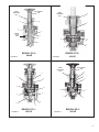
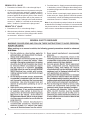
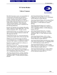
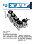
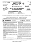
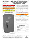
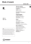
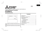
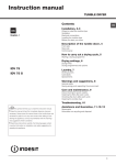
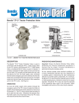
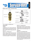
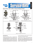
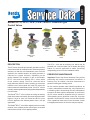
SD-03-3611
Bendix® PP-1®, PP-2™, PP-5™, PP-8™, & RD-3™ Push-Pull Type
Control Valves
BENDIX® PP-1®
VALVE
BENDIX® PP-5™
VALVE
BENDIX® PP-2™
VALVE
BENDIX® RD-3™
VALVE
BENDIX® PP-8™
VALVE
FIGURE 1 - PUSH-PULL TYPE CONTROL VALVES
DESCRIPTION
The PP valves are push-pull manually operable on-off air
control valves with an exhaust function. Most are pressure
sensitive, so that they will automatically move from the
applied to the exhaust position as supply pressure is
reduced to a certain minimum, depending on the
spring installed. The exception to this is the Bendix®
PP-8 ™ valve and some Bendix ® PP-1 ® valves which
do not contain a spring. The PP-8™ valve also has a
larger diameter shaft for button mounting so that when
installed on the same panel with other PP valves the
buttons cannot be inadvertently mixed. The PP-8™ valve is
normally used to operate tractor spring brakes independently
from the trailer.
The Bendix® PP-5™ valve is unique in having an auxiliary
piston in the lower cover which, upon receiving a pneumatic
signal of 18 psi or more, will cause the valve to move
from the applied to the exhaust position from a 100 psi
application.
The PP-2™ valve has an auxiliary port which may be
plumbed into a service brake line to release the spring
brakes if a service application is made, preventing
compounding of forces on the foundation brakes.
PREVENTIVE MAINTENANCE
Important: Review the Bendix Warranty Policy before
performing any intrusive maintenance procedures. A
warranty may be voided if intrusive maintenance is
performed during the warranty period.
No two vehicles operate under identical conditions, as
a result, maintenance intervals may vary. Experience is
a valuable guide in determining the best maintenance
interval for air brake system components. At a minimum,
the PP valves should be inspected every 6 months or
1500 operating hours, whichever comes first, for proper
operation. Should the PP valves not meet the elements
of the operational tests noted in this document, further
investigation and service of the valve may be required.
The Bendix® RD-3™ valve differs slightly in that it normally
remains in the exhaust position and requires a constant
manual force to hold it in the applied position.
1
Bendix®
Valve
Automatic
Exhaust
Momentary
Apply
Pilot Trip
Feature
NonAutomatic
PP-1®
20, 30, 40
or 60 psi
-
-
-
™
40 psi
-
-
-
PP-5™
40 psi
-
18 psi
-
™
RD-3
-
Must be held manually
-
-
PP-8™
-
-
-
Will remain in
either position
PP-2
PANEL
MOUNTING
NUT
9
6
Block and/or hold the vehicle by a means other than air
brakes and drain all reservoirs.
2. Mark each air supply line and its port for easy
reinstallation, then disconnect them. Remove the valve
from the panel by removing the panel mounting nut.
FIGURE 2
2. Reconnect the air lines using marks made during
removal as a guide.
3. Install the operating button. Secure the operating button
by installing the button roll pin.
DISASSEMBLY: BENDIX PP-1 , PP-8 AND
RD-3™ VALVES
®
®
™
1. Remove the two cap screws (3) which retain the lower
cover and remove the cover. Remove the sealing ring
(4).
2. Insert a small punch through the roll pin hole in the stem
and remove the locknut (5).
3. Remove the inlet-exhaust valve (6) and plunger (7) and
spring (8), if any.
4. Remove o-ring (9) from plunger.
DISASSEMBLY: BENDIX® PP-5™ VALVE
1. Perform same operations as for PP-1® valve.
2. Remove the inlet seal (10), shown in Figure 4, from
lower cover. Remove the ring diaphragm (4) from the
inlet seat.
3. Remove piston (11) and o-ring (2).
DISASSEMBLY: BENDIX® PP-2™ VALVE
1. Insert a small punch through the roll pin hole in the
plunger and remove the locknut (1) from the plunger.
2. Withdraw the plunger and remove the spring (9) and
o-ring (8).
2
4
5
1. Drive the button roll-pin out with a punch and remove
the button.
1. Install the valve in panel, securing with the panel
mounting nut.
7
8
REMOVAL
INSTALLATION
BUTTON ROLL
PIN
3
BENDIX® PP-1®
VALVE
3. Remove the two machine screws (2) and remove the
lower cover (3).
4. Remove the inlet-exhaust valve (4) and piston (5).
5. Remove o-rings (6 & 7) from piston.
OPERATING AND LEAKAGE TESTS
BENDIX® PP-1®, PP-8™ AND RD-3™ VALVES
1. An accurate test gauge should be tee’d into the supply
line as a means of controlling the supply pressure
provided. Apply a 120 psi air source to the supply port.
A small volume reservoir (e.g. 90 cu. in.), with a gauge,
should be connected to the delivery port.
2. With 120 psi supply pressure, and the button pulled out
(exhaust position), leakage at the exhaust port should
not exceed a 1” bubble in 5 seconds; at the plunger
stem a 1” bubble in 5 seconds. There should be no
leakage between the upper and lower body.
3. Push the button in (applied position). Leakage at
the exhaust port should not exceed a 1” bubble in
3 seconds; at the plunger a 1” bubble in 3 seconds.
(The RD-3™ valve will have to be manually held in this
position.)
4. Reduce the supply pressure. At a pressure from 60 to
20 psi, depending on the spring installed, the button
should pop out automatically, exhausting the delivery
volume. (This does not apply to the RD-3™, PP-8™ or some
PP-1® valves).
BUTTON ROLL
PIN
PANEL
MOUNTING
NUT
PANEL
MOUNTING
NUT
9
8
9
7
4
2
BRAKE
VALVE
PORT
3
6
6
5
4
7
3
1
FIGURE 3
5
BENDIX® PP-2™
VALVE
BENDIX® PP-8™
VALVE
FIGURE 5
BUTTON ROLL
PIN
PANEL
MOUNTING
NUT
9
9
7
7
8
8
6
10
6
4
4
5
5
3
3
11
2
FIGURE 4
BENDIX® PP-5™
VALVE
FIGURE 6
BENDIX® RD-3™
VALVE
3
BENDIX® PP-5™ VALVE
1. Proceed as for Bendix PP-1 valve through Step 3.
®
®
2. Connect a modulated source of air pressure to the pilot
air inlet. With the button pushed in (applied position)
with 125 psi supply pressure and a gradually increasing
pressure applied at the pilot air port the valve should
move to the release position with a pilot pressure of
not more than 18 psi. Leakage in this mode should not
exceed a 1” bubble in 3 seconds at the exhaust port
and a 1” bubble in 5 seconds at the plunger stem.
BENDIX® PP-2™ VALVE
1. Proceed as for PP-1® valve through Step 1.
3. Push the button in. Supply pressure should be present
in the delivery volume. Leakage at the exhaust port or
around the plunger stem should not exceed a 1” bubble
in 5 seconds.
4. Pull the button out and apply supply pressure at the
brake valve port. Supply pressure should be present
in the delivery volume and leakage at the exhaust port
should not exceed a 1” bubble in 5 seconds.
Note: If any of the above push-pull valves do not function
as described or if leakage is excessive, it is recommended
they be returned to our nearest authorized distributor for a
service new or remanufactured replacement.
2. With the button pulled out (exhaust position), leakage
at the brake valve port or at the plunger stem should
not exceed a 1” bubble in 5 seconds.
4
BW1578 © 2011 Bendix Commercial Vehicle Systems LLC, a member of the Knorr-Bremse.Group • 5/2011 • All rights reserved.