1
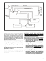
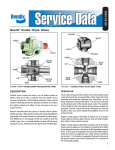
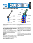
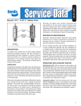
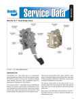
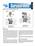
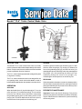
SD-03-821
®
Bendix® TC-6™ Trailer Control Brake Valve
8
14
10
KNOB
11
13
9
7
6
12
5
15
EXHAUST
FIGURE 2
FIGURE 1
DESCRIPTION
®
™
The Bendix TC-6 trailer control brake valve is normally
used to operate the trailer brakes independently of the tractor
brakes. It may be used, however, wherever a hand controlled
pressure graduation function is desired.
The TC-6™ valve is handle operated and is designed for panel
or dog house mounting.
The TC-6™ trailer control brake valve is not designed for use
as a parking brake control and should never be used to
hold the brakes applied when the operator leaves the vehicle.
OPERATION
APPLYING
When the handle (item 10) is pulled through its 75° arc, the
roller cam (item 11) is rotated accordingly. The cam action
forces the cam follower (item 9) downward, compressing
the graduating spring (item 6) and creating a force on the
plunger (item 12) which depresses the inlet valve (item 2)
and delivers air under pressure to the delivery port.
4
2
3
DELIVERY
1
16
SUPPLY
HOLDING
As delivery pressure builds up in the delivery port, it is also
effective under the plunger (12) causing it to balance the
force of the graduating spring (6) until the inlet valve (2) is
seated against its seat in the body and is also seated against
the plunger (12), thus preventing the delivery air from
exhausting through the center of the plunger (12),
maintaining the desired pressure in the delivery line.
RELEASING
When the handle is released or moved to its release position,
the cam follower (9) is permitted to rise, opening the exhaust
passage and allowing the air pressure in the delivery line to
exhaust out the exhaust port.
PREVENTIVE MAINTENANCE
Important: Review the Bendix Warranty Policy before
performing any intrusive maintenance procedures. A warranty
may be voided if intrusive maintenance is performed during
the warranty period.
1
No two vehicles operate under identical conditions, as a
result, maintenance intervals may vary. Experience is a
valuable guide in determining the best maintenance interval
for air brake system components. At a minimum, the TC-6™
valve should be inspected every 6 months or 1500 operating
hours, whichever comes first, for proper operation. Should
the TC-6™ valve not meet the elements of the operational
tests noted in this document, further investigation and service
of the valve may be required.
If the valve does not function as described, or if the leakage
is excessive, it is recommended that it be returned to the
nearest Bendix authorized distributor for a factory
remanufactured valve under the exchange plan. If this is not
possible, the valve can be repaired with genuine Bendix parts,
in which case the following should be helpful. The
maintenance kit for the TC-6™ valve is part number 289890.
Every 900 hours, 25,000 miles or every 3 months, drop some
lubricant such as BW-650M silicone lubricant (Bendix part
number 291126) (Dow Corning 55-M) through the handle
operating slot, to re-lubricate the cam roller and hinge pin.
Perform operating and leakage tests.
Remove the valve from the panel. Place the lever in a vise
and with a firm pull the rubber handle may be removed.
Remove the two slotted head cap screws (14) which hold
the mounting bracket in place as shown in Fig. 2 and remove
the mounting bracket.
REMOVING AND INSTALLING
Secure vehicle with spring brakes or blocks. Drain the
reservoir which supplies the TC-6™ valve. Remove the
fasteners which secure the mounting bracket to the panel.
Disconnect the connecting air lines. Remove valve.
INSTALLING
A typical piping arrangement for the TC-6™ valve is shown in
Fig. 3. Check connecting air lines for integrity and foreign
material. Replace lines if necessary. Re-connect air lines.
Replace fasteners securing bracket to panel. Check
operation of valve by charging system and performing the
service check as described in this manual.
SERVICE CHECKS
OPERATING
Connect an accurate test gauge to the trailer service line
hose and leave the trailer emergency or supply hose
connected to the trailer or if a trailer is not available, connect
the trailer supply hose to an unvented dummy coupling or
to a plugged hose fitting. The trailer supply valve should be
in the normal position.
When the operating lever is moved to the fully applied
position, the gauge should register full reservoir pressure.
Intermediate positions should deliver proportional
intermediate pressures. Upon release, the gauge should
immediately register zero.
The location of the atmospheric end of the exhaust line
from the valve should be found, probably in the engine
compartment.
With the TC-6™ valve in the release position, no pressure
should register on the test gauge and leakage at the end of
the exhaust line should not be greater than 100 SCCM
(1" bubble in 5 seconds).
With the valve fully applied, leakage at the exhaust line
should not be greater than 175 SCCM (1" bubble in 3
seconds).
2
DISASSEMBLY
Drive the pivot pin (13) out of the body with a drift punch.
The handle (10), roller cam (11) and torsion spring (8) may
now be removed. Remove the roller cam from the handle.
The cam follower (9), graduating spring (6), plunger (12),
and plunger return spring (4) may now be removed through
the top of the valve. Care should be taken not to lose washer
(15).
Place the body in a soft-jawed vise and remove cap nut (16).
Remove o-ring (1) from cap nut.
Inlet valve spring (3) and inlet valve (2) may now be removed.
CLEANING AND INSPECTION OF PARTS
Clean all metal and plastic parts with mineral spirits or
equivalent. Wipe all o-rings and rubber parts dry. Replace
any which show signs of wear or deterioration. Inspect
valve seats for nicks or burrs and remove any deposits.
Check all springs for distortion, cracks and corrosion.
Replace all parts not considered serviceable after inspection.
ASSEMBLY
Before assembling the valve all bores, cam, pivot pin,
plungers, and o-rings should be lubricated with silicone
lubricant Dow Corning 55-M (Bendix part number 291126).
Place body in a soft-jawed vise with ports pointing up. Place
inlet valve (2) in inlet cavity and install inlet valve spring (3).
Place o-ring (1) on cap nut (16) and assemble cap nut in
body. Torque cap nut to 50-150 inch pounds.
Install o-rings (5) and (7) on plunger (12) and cam follower
(9). Caution: o-ring (7) is slightly larger than (5) and goes on
the cam follower (9).
Reverse position of body in vise and install plunger return
spring (4), plunger (12), washer (15), graduating spring
(6), and cam follower (9). Note: The cam follower must be
positioned so that the projection on the side of the body
matches the corresponding groove in the body.
DOUBLE CHECK VALVE
SERVICE LINE
TP-3™
VALVE
TC-6™ VALVE
TO REAR BRAKES
DOUBLE
CHECK
VALVE
TO FRONT
BRAKES
REAR BRAKE
RESERVOIR
SUPPLY RESERVOIR
FRONT BRAKE
RESERVOIR
FIGURE 3
Position the torsion spring (8) in its approximate position in
the body so that the end which engages the handle rests
against the side of the body opposite the bracket retaining
screw holes. Place the roller cam (11) in position as shown
in Fig. 2 and insert pivot pin (13) through the torsion spring
and partially through the roller cam, leaving room to insert
the wedge shaped end of the handle.
With a small screwdriver or similar tool, force the tang of the
torsion spring towards the opposite wall of the body far
enough so the handle (10) may be inserted into the roller
cam. The pivot pin (13) may then be tapped on through
until the ends of the pin are flush with either side of the
body.
Place the mounting bracket in position and secure with two
slotted head cap screws (14).
Place the rubber knob back on the handle. Reinstall the
valve on the vehicle and test per “operating leakage checks”
in this manual.
WARNING! PLEASE READ AND FOLLOW
THESE INSTRUCTIONS TO AVOID
PERSONAL INJURY OR DEATH:
When working on or around a vehicle, the following
general precautions should be observed at all times.
1. Park the vehicle on a level surface, apply the
parking brakes, and always block the wheels.
Always wear safety glasses.
2. Stop the engine and remove ignition key when
working under or around the vehicle. When
working in the engine compartment, the engine
should be shut off and the ignition key should be
removed. Where circumstances require that the
engine be in operation, EXTREME CAUTION should
be used to prevent personal injury resulting from
contact with moving, rotating, leaking, heated or
electrically charged components.
3. Do not attempt to install, remove, disassemble or
assemble a component until you have read and
thoroughly understand the recommended
procedures. Use only the proper tools and observe
all precautions pertaining to use of those tools.
3
4. If the work is being performed on the vehicle’s air
brake system, or any auxiliary pressurized air
systems, make certain to drain the air pressure from
all reservoirs before beginning ANY work on the
vehicle. If the vehicle is equipped with an AD-IS™
air dryer system or a dryer reservoir module, be
sure to drain the purge reservoir.
5. Following
the
vehicle
manufacturer’s
recommended procedures, deactivate the electrical
system in a manner that safely removes all
electrical power from the vehicle.
6. Never exceed manufacturer’s recommended
pressures.
7. Never connect or disconnect a hose or line
containing pressure; it may whip. Never remove a
component or plug unless you are certain all
system pressure has been depleted.
4
8. Use only genuine Bendix ® replacement parts,
components and kits. Replacement hardware,
tubing, hose, fittings, etc. must be of equivalent
size, type and strength as original equipment and
be designed specifically for such applications and
systems.
9. Components with stripped threads or damaged
parts should be replaced rather than repaired. Do
not attempt repairs requiring machining or welding
unless specifically stated and approved by the
vehicle and component manufacturer.
10. Prior to returning the vehicle to service, make
certain all components and systems are restored to
their proper operating condition.
BW1567 © 2004 Bendix Commercial Vehicle Systems LLC. All rights reserved. 3/2004 Printed in U.S.A.