1
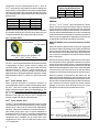
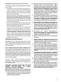
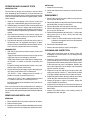
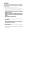
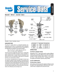
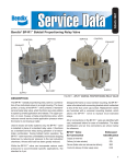
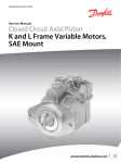
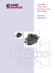
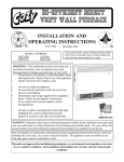
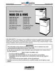
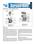
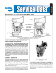
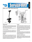
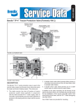
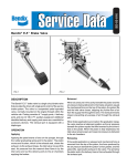
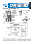
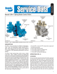
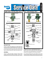
SD-03-4020
®
Bendix® SV-1™ Synchro Valve SV-3™ & SV-4™ Trailer Release Valve
CONTROL
CONTROL
EXHAUST
EXHAUST
DELIVERY
DELIVERY
SV-3™
VALVE
SUPPLY
SUPPLY
1/4" P.T.
CONTROL
1/4" P.T.
CONTROL
CAP NUT
O-RING
O-RING
PISTON
SV-4™
VALVE
CAP NUT
O-RING
PISTON
O-RING
PISTON SPRING
PISTON
SPRING
O-RING
1/8" P.T.
EXHAUST
O-RING
BODY
1/8" P.T.
EXHAUST
1/4" P.T.
DELIVERY
1/4" P.T.
DELIVERY
BODY
VALVE
SPRING
VALVE
O-RING
SPRING
GUIDE
SPRING
GUIDE
VALVE
VALVE
SPRING
O-RING
CAP NUT
CAP NUT
1/4" P.T.
SUPPLY
1/4" P.T.
SUPPLY
FIGURE 1 - SV-1™ SYNCHRO VALVE
CHECK VALVE
DESCRIPTION
The SV-1™ synchro valve and the SV-3™ trailer release valve
are pilot operated, non-graduating pneumatic control valves.
These valves are used to control air from a remote supply,
have set opening and closing pressures and can be used to
delay or sequence the action of other pneumatic devices.
DETAIL OF SV-3™
VALVE
DETAIL OF SV-4™
VALVE
FIGURE 2 - SV-3™ & SV-4™ TRAILER RELEASE VALVE
GENERAL
sequence various devices and events in the air brake system.
These valves can be operated either in an automatic or
manual mode using different air connection methods.
The SV-1™ synchro valve (figure 1) and SV-3™ & SV-4™ trailer
release valves (figure 2) are air controlled, “On-Off” (nongraduating) control valves that are primarily used to delay or
Two .28 inch mounting holes are provided in the die cast
aluminum body for panel or frame mounting. Two hex cap
nuts at the ends of the cylindrical valve body retain the internal
1
components. The air connection ports for SV-1™, SV-3™ &
SV-4™ valves are the same and are located in relatively the
same position on each model. All connections are pipe thread.
Lettering embossed in the valve body identifies two of the
four connection ports in these valves. Refer to the chart below
and figure one.
Air Connection
Air Supply
Delivery
Control
Exhaust
Body Ident. Thread Size
SUP
1/4" PT
DEL
1/4" PT
None
1/4" PT
None
1/8" PT
IMPORTANT: An exhaust check valve should be installed in
the threaded exhaust port of these valves when they are
mounted outside the cab in unprotected environments.
SV-1™ Synchro Valve
1/8" PIPE THREAD
1/8" PIPE THREAD
Note: Either style may be installed in the
SV-1™, SV-3™ or SV-4™ valves
FIGURE 3 - EXHAUST CHECK VALVE STYLES
The SV-1™ valve is a general purpose valve used in a variety
of applications on trucks, buses, tractors, trailers and
converter dollies. The SV-1™ valve is the base valve from
which both the SV-3™ and SV-4™ valves are derived. It is
offered in a variety of pressure settings to accommodate
applications where automatic operation is required. It is easily
distinguished from the SV-3™ and SV-4™ valve by its smaller
size.
SV-3™ Trailer Release Valve
While originally designed for automatic operation to
accomplish brake release on trailers without spring brakes,
the SV-3™ valve can be used in any installation where its
single automatic pressure setting is advantageous. The
SV-3™ valve is very similar in appearance to the SV-4™ valve
but can be distinguished by measuring the length and
diameter of the supply hex cap nut (1/4" PT supply port).
See the comparison chart for the dimensions.
SV-3™/SV-4™ Valve Comparison
Supply Cap Nut Dimensions
Diameter Length
SV-3
.8125"
1.162"
SV-4
.94"
1.062"
OPERATION
GENERAL
The SV-1™, SV-3™, & SV-4™ valves all operate in a similar
fashion. All can be connected in the air system so that other
valves control them. When connected in this non-automatic
mode the valve serves as a remote mounted, On-Off control.
They can also be installed so that they function automatically
or self actuate at a preset pressure. Automatic operation is
the most common application. Regardless of how they are
connected the internal valve operation is the same.
NON-AUTOMATIC (valve controlled remotely by another
valve)
With no air pressure present at the control port, supply port
air pressure and the inlet/exhaust valve spring hold the inlet
valve on its seat in the body. The piston is held away from
the inlet/exhaust valve by the piston spring, and the delivery
line is vented to atmosphere through the hollow exhaust
stem of the piston.
When sufficient air pressure is applied to the control port,
the control piston moves against the resistance of its return
spring. As the control piston moves, it contacts the exhaust
valve portion of the inlet and exhaust valve which seals the
hollow exhaust passage in the piston stem. Continued piston
movement drives the inlet valve from its seat and allows
supply air to flow through the body and out the delivery port.
When air pressure is removed from the control port, the
piston return spring and delivery port air pressure move the
piston away from the inlet/exhaust valve. As the piston moves,
the inlet valve re-seats itself preventing air flow to the delivery
port. Continued movement unseats the hollow exhaust
passage in the piston stem allowing delivery air to flow
through the stem and out the exhaust check valve.
SV-4™ Trailer Release Valve
The SV-4™ valve was designed primarily for use on trailer
converter dollies to minimize the possibility of false charging.
Like the SV-3™ valve it can be used in other applications.
The SV-4™ valve is the combination of two valves; an SV-3™
valve and a single check valve. A typical installation is
illustrated in figure 4. The SV-4™ valve can be distinguished
from the SV-3™ valve using the dimensions given in the
comparison chart. In addition, the tip of the check valve
contained in the SV-4™ valve is visible at the bottom of the
¼" PT supply port.
2
SINGLE CHECK VALVE
SV-1™
SYNCHRO
Note:
An SV-4™ valve can be used in place of the
SV-1™ valve and single check valve shown here.
FIGURE 4 - TRAILER CONVERTER DOLLY
AUTOMATIC (self actuating at a pre-set pressure)
There are two methods for accomplishing automatic operation
of an SV valve.
1. One method for affecting automatic operation is to
connect the SV valve control port to its supply port using
a pipe or tubing tee. This is referred to as “common
control and supply” since the pressure at the supply
and control port is the same.
With common control and supply, the valve opens
(delivers air) on ascending supply air pressure and closes
and exhausts on descending pressure. The pressure at
which delivery and exhaust occurs differs for various part
numbers. Opening and exhaust pressure is specified
for the various part numbers.
2. SV valves can be made to operate automatically even
when the supply port and control ports are separate (not
connected as described in #1 above).
The SV valve will open (deliver air) and close (and
exhaust) when control port pressure is increased or
decreased. Consult Bendix Engineering for specific
control port pressure for valve opening and closing when
this type of automatic operation is used. When using
the SV-1™ synchro valve in this manner, the control signal
ramp rate should be limited by orificing or other methods.
Please contact Bendix Engineering with specific
application requirements.
PREVENTIVE MAINTENANCE
Important: Review the Bendix Warranty Policy before
performing any intrusive maintenance procedures. A warranty
may be voided if intrusive maintenance is performed during
the warranty period.
No two vehicles operate under identical conditions, as a
result, maintenance intervals may vary. Experience is a
valuable guide in determining the best maintenance interval
for air brake system components. At a minimum, the SV
valves should be inspected every 6 months or 1500 operating
hours, whichever comes first, for proper operation. Should
the SV valves not meet the elements of the operational tests
noted in this document, further investigation and service of
the valve may be required.
If the SV-1™, SV-3™, or SV-4™ valve fails to function as
described or leakage is excessive, it should be repaired or
replaced with a genuine Bendix unit, available at any
authorized parts outlet.
WARNING! PLEASE READ AND FOLLOW
THESE INSTRUCTIONS TO AVOID
PERSONAL INJURY OR DEATH:
2. Stop the engine and remove ignition key when
working under or around the vehicle. When
working in the engine compartment, the engine
should be shut off and the ignition key should be
removed. Where circumstances require that the
engine be in operation, EXTREME CAUTION should
be used to prevent personal injury resulting from
contact with moving, rotating, leaking, heated or
electrically charged components.
3. Do not attempt to install, remove, disassemble or
assemble a component until you have read and
thoroughly understand the recommended
procedures. Use only the proper tools and observe
all precautions pertaining to use of those tools.
4. If the work is being performed on the vehicle’s air
brake system, or any auxiliary pressurized air
systems, make certain to drain the air pressure from
all reservoirs before beginning ANY work on the
vehicle. If the vehicle is equipped with an AD-IS™
air dryer system or a dryer reservoir module, be
sure to drain the purge reservoir.
5. Following
the
vehicle
manufacturer’s
recommended procedures, deactivate the electrical
system in a manner that safely removes all
electrical power from the vehicle.
6. Never exceed manufacturer’s recommended
pressures.
7. Never connect or disconnect a hose or line
containing pressure; it may whip. Never remove a
component or plug unless you are certain all
system pressure has been depleted.
8. Use only genuine Bendix ® replacement parts,
components and kits. Replacement hardware,
tubing, hose, fittings, etc. must be of equivalent
size, type and strength as original equipment and
be designed specifically for such applications and
systems.
9. Components with stripped threads or damaged
parts should be replaced rather than repaired. Do
not attempt repairs requiring machining or welding
unless specifically stated and approved by the
vehicle and component manufacturer.
10. Prior to returning the vehicle to service, make
certain all components and systems are restored to
their proper operating condition.
11. For vehicles with Antilock Traction Control (ATC),
the ATC function must be disabled (ATC indicator
lamp should be ON) prior to performing any vehicle
maintenance where one or more wheels on a drive
axle are lifted off the ground and moving.
When working on or around a vehicle, the following
general precautions should be observed at all times.
1. Park the vehicle on a level surface, apply the
parking brakes, and always block the wheels.
Always wear safety glasses.
3
OPERATING AND LEAKAGE TESTS
OPERATING TEST
Two accurate air gauges are necessary to perform these
tests. Depending upon installation, it may be necessary to
remove valve to properly test it. Correct opening pressures
of the valve should be known before beginning tests; consult
vehicle manual.
1. Install an accurate gauge in the common control and
supply line; install another gauge in the delivery port.
2. Gradually apply air pressure to the common supply and
control line. As common supply and control pressure
increases, note at what pressure delivery of air through
valve is made and compare with specifications in vehicle
manual.
3. Slowly decrease pressure in the common supply and
note at what pressure delivery line pressure is vented;
compare with vehicle manual.
4. Pay particular attention to the exhaust check valve in
the exhaust port if so equipped (note figure 3). Make
certain it is free of contamination and the rubber valve is
free to function. Replace this item as necessary.
LEAKAGE TEST
1. With 120 psi air pressure present in supply, control and
delivery ports:
- Apply a soap solution around control port cap nut and
supply port cap nut. No leakage is permitted.
- Apply soap solution to the exhaust port; leakage must
not exceed a 1" bubble in less than 5 seconds (100
sccm).
Excessive leakage would indicate a faulty o-ring, inlet/
exhaust valve or piston exhaust seat.
2. Plug the delivery port and apply 10 psi to the supply port
only. Apply soap solution to the exhaust port:
-For the SV-1™ valve - leakage must not exceed a 1"
bubble in less than 5 seconds (100 sccm).
-For the SV-3™ & SV-4™ valve - leakage must not exceed
a 1" bubble in less than 10 seconds (50 sccm).
Excessive leakage would indicate a faulty inlet valve or
inlet valve seat.
If the valve does not function as described or if leakage is
excessive, it is recommended that it be replaced with a new
unit, or repaired with genuine Bendix parts available at Bendix
outlets.
REMOVING AND INSTALLING
REMOVING
1. Block and hold vehicle by means other than air brakes.
2. Drain air brake system.
3. Identify the air lines to facilitate reinstallation, disconnect
the lines, remove the mounting bolts, and then the valve.
4
INSTALLING
1. Mount the valve securely.
2. Check and clean air lines; identify air lines and connect
to valve.
DISASSEMBLY
1. Remove the control port cap nut and its o-ring. Remove
the o-ring from the cap nut.
2. Remove the piston from the valve body. Remove the large
and small piston o-rings from the piston.
3. Remove the piston return spring from the body.
4. Remove the supply port cap nut and its o-ring. Remove
the o-ring from the cap nut.
5. Remove the inlet/exhaust valve stop (SV-1™ valve) or the
spring guide (SV-3™ & SV-4™ valve), then the inlet/
exhaust valve spring.
Note: The SV-4™ valve contains a check valve which is
installed in the opposite end of the inlet/exhaust
valve return spring.
6. Remove the inlet/exhaust valve.
7. Remove the exhaust check valve if so equipped.
CLEANING AND INSPECTION
1. Using good commercial grade of solvent, clean and
thoroughly dry all metal parts. Do not damage bores
with metal tools.
2. Inspect the interior and exterior of all metal parts that
will be reused for severe corrosion, pitting and cracks.
Superficial corrosion and/or pitting on the exterior portion
of the body and cap nuts is acceptable. Replace the
entire valve if the interior of the body or cap nuts exhibit
signs of corrosion or pitting.
3. Inspect the body bore and the check valve seat in the
supply port cap nut of the SV-4™ valve for deep scuffing
or gouges. Replace the entire valve if either are found.
4. Inspect the pipe threads in the body and cap nuts. Make
certain they are clean and free of thread sealant.
5. Inspect all springs for signs of corrosion, pitting and
cracks. Replace as necessary.
6. Inspect all air line fittings for corrosion and replace as
necessary. Make certain to remove all old thread sealant
before reuse.
7. Inspect the exhaust check valve making certain all
passages are clear and open.
ASSEMBLY
Prior to assembly, lubricate the piston, o-rings and body
bores with Dow-Corning 55-M pneumatic grease (Bendix
Pc. No. 291126).
1. Install the inlet/exhaust valve in the body.
2. Install the inlet valve spring and valve stop (SV-1™ valve)
or spring guide (SV-3™ & SV-4™ valve). NOTE: Install
the check valve in the small diameter end of the inletexhaust valve return spring of the SV-4™ valve before
installing in the body.
3. Install the o-ring on the supply cap nut then install and
tighten the cap nut. Torque to approximately 100 inch
pounds.
4. Install piston return spring in body.
5. Install the small and large diameter o-rings on the piston.
Insert the piston into body. (Piston should now rest on
top of spring.)
6. Install the control port cap nut o-ring on the cap nut then
install and tighten the cap nut in body. Torque to
approximately 275 inch pounds.
7. Install the exhaust check valve if the valve assembly
was so equipped.
8. Perform tests as outlined in the “Operating and Leakage
Tests” section.
5
6
BW1574 © 2004 Bendix Commercial Vehicle Systems LLC. All rights reserved. 10/2004 Printed in U.S.A.