1
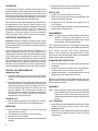
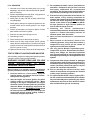
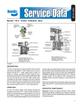
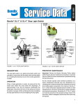
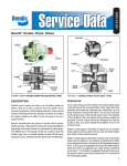
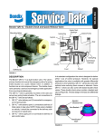
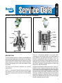
SD-06-1600
Bendix® LP-2™ & LP-3™ Low Pressure Indicators
COVER
COVER
DIAPHRAGM
SPRING
CONTACT
POINTS
SPRING
CONTACT
POINTS
PISTON
BODY
BODY
O-RING
DIAPHRAGM
FIGURE 1 - LP-2™ LOW PRESSURE INDICATOR
DESCRIPTION
The low pressure indicator is a safety device designed to
give an automatic warning to the driver whenever air pressure
in the air brake system is below the safe minimum for normal
vehicle operation. It is usually used to operate an electrical
buzzer or warning light, or both, which are audible or visible
to the driver.
Two styles of low pressure indicators are currently
manufactured.
The LP-2™ low pressure indicator, which is the older style
and consists of a die cast body with a spring loaded
diaphragm clamped between the body and the Bakelite
cover.
FIGURE 2 - LP-3™ LOW PRESSURE INDICATOR
The LP-3™ low pressure indicator is the newer style,
consisting of a die cast body, nylon cover and employs a
spring loaded o-ring diaphragm and piston. The LP-3™
indicator is available with either one terminal or two. The
single terminal unit utilizes a metallic gasket between body
and case to ground the lower contract strip. The two terminal
unit utilizes a phenolic insulating gasket to isolate both
terminals from the vehicle frame.
The electrical contacts provided in both the LP-2™ and LP-3™
indicators remain closed by spring force until the air brake
system pressure below the diaphragm is above the setting
(force) of the low pressure indicator spring. The setting of
the indicator and piece number is marked on a label on the
valve body. If a label is not present, then the vehicle manual
should be consulted for the proper setting. The nominal
setting of the indicator is 60 psi; however, pressure settings
may vary depending upon the vehicle.
1
OPERATION
To describe the operation, we shall assume that the low
pressure indicator is set for 60 psi. When air pressure at the
supply port and under the diaphragm is above 60 psi, the
electrical contacts remain open because the force exerted
by air pressure underneath the diaphragm overcomes the
force exerted by the spring above the diaphragm.
When air pressure below the diaphragm drops below 60 psi,
the spring exerts a force which is greater than the force
exerted by the air pressure below the diaphragm. This causes
the diaphragm (and the piston in the LP-3™ indicator) to
move and allow the electrical contacts to close. This
completes or closes the electrical circuit to the warning
device, warning the driver of low air pressure in the system.
PREVENTIVE MAINTENANCE
Important: Review the Bendix Warranty Policy before
performing any intrusive maintenance procedures. A warranty
may be voided if intrusive maintenance is performed during
the warranty period.
No two vehicles operate under identical conditions; as a
result, maintenance intervals may vary. Experience is a
valuable guide in determining the best maintenance interval
for air brake system components. At a minimum, the low
pressure indicator should be inspected every 6 months or
1500 operating hours, whichever comes first, for proper
operation. Should the low pressure indicator not meet the
elements of the operational tests noted in this document,
further investigation and service of the valve may be required.
TESTING FOR SERVICEABILITY
OPERATING TEST
1. If possible, determine the setting of the low pressure
indicator by referring to the label on the valve or the vehicle
manual.
2. Operation of the low pressure indicator may be checked
with ignition switch “on” by reducing the system pressure
and observing that low pressure warning occurs when
system pressure drops below the setting of the low
pressure indicator. The contacts will be closed when
the warning device operates. If the setting of the indicator
is unknown, the contacts should close between
approximately 70 psi and 50 psi.
LEAKAGE TEST
1. With air pressure present at the supply port, coat the
indicator with soap solution. No leakage permitted.
REMOVING
1. Block the wheels. Otherwise, secure the vehicle with
other than service brakes.
2. The ignition switch should be in the “off” position.
3. Drain the air from the system.
4. Disconnect the electrical connections at the low pressure
indicator.
2
5. Disconnect the air line and mounting bolts or unscrew
the Indicator from the fitting and remove.
INSTALLING
1. Install in a convenient location for servicing.
2. Connect to a reservoir pressure line at a high point in the
system for adequate drainage.
3. If installing an LP-2™ indicator, use a supply line of 1/4
O.D. minimum.
4. Connect the Indicator terminals in series with the ignition
switch and the warning device.
DISASSEMBLY
NOTE: It is generally recommended that the low pressure
indicator, if faulty, be replaced with a new unit;
however, service parts are available; and if repairs
are necessary, the following will apply:
LP-2™ indicator. Unscrew the cover retainer from the body.
Remove cover and remove spring and diaphragm assembly.
LP-3™ indicator. Remove cover screws, lockwashers.
Remove cover, contact disc, spring, and shim(s). (Note:
Shims may or may not be present.) Remove contact plate,
gasket, piston, and o-ring diaphragm.
CLEANING AND INSPECTION
1. Clean all metal parts in mineral spirits and dry them
completely.
2. Inspect all parts for excessive wear or deterioration.
Check the valve spring for cracks or corrosion.
3. Inspect contact points. If contact points are not severely
pitted, they can be dressed with a fine file.
Replace all parts that were discarded and any parts not
found to be serviceable during inspection, using only genuine
Bendix replacement parts.
ASSEMBLY
NOTE: When using pipe thread sealant during assembly
and installation, take particular care to prevent the
sealant from entering the valve itself. Apply the
sealant beginning with the second thread back from
the end.
LP-2™ INDICATOR
1. Place and position the diaphragm assembly in the body.
Position the spring so that it rests on the upper
diaphragm follower.
2. Place cover over the diaphragm and screw cover retainer
to the body and tighten securely. (Torque to 110-130
inch pounds.)
LP-3™ INDICATOR
1. Lubricate bore of body and both sides of the o-ring
diaphragm with silicone lubricant BW-650-M (Bendix
piece no. 291126).
2. Install o-ring diaphragm in body. (Note: o-ring portion of
diaphragm should face supply port.)
3. Install piston in body. Flat side of piston should face
o-ring diaphragm.
4. Install gasket. (Always use a phenolic gasket in a two
terminal switch and a metallic gasket in the single
terminal.)
5. Position contact plate over fingers of piston. Contact
plate should rest on face of gasket.
6. If shim(s) are used, place shim(s) in cover.
7. Place spring in cover.
8. Place contact point so that it rests on spring.
9. Install cover on body, using machine screws, making
certain that the contact plate is in position over fingers
of piston, and arm of contact plate is positioned so that
it will fit in groove of cover.
10. Tighten screws securely. (Torque to 20-30 inch pounds).
TEST OF REBUILT LOW PRESSURE INDICATOR
After rebuilding, perform the leakage and operating tests as
outlined in section “Testing for Serviceability.”
WARNING! PLEASE READ AND FOLLOW
THESE INSTRUCTIONS TO AVOID
PERSONAL INJURY OR DEATH:
When working on or around a vehicle, the following
general precautions should be observed at all times.
1. Park the vehicle on a level surface, apply the
parking brakes, and always block the wheels.
Always wear safety glasses.
2. Stop the engine and remove ignition key when
working under or around the vehicle. When
working in the engine compartment, the engine
should be shut off and the ignition key should be
removed. Where circumstances require that the
engine be in operation, EXTREME CAUTION should
be used to prevent personal injury resulting from
contact with moving, rotating, leaking, heated or
electrically charged components.
3. Do not attempt to install, remove, disassemble or
assemble a component until you have read and
thoroughly understand the recommended
procedures. Use only the proper tools and observe
all precautions pertaining to use of those tools.
4. If the work is being performed on the vehicle’s air
brake system, or any auxiliary pressurized air
systems, make certain to drain the air pressure from
all reservoirs before beginning ANY work on the
vehicle. If the vehicle is equipped with an AD-IS®
air dryer system or a dryer reservoir module, be
sure to drain the purge reservoir.
5. Following
the
vehicle
manufacturer’s
recommended procedures, deactivate the electrical
system in a manner that safely removes all
electrical power from the vehicle.
6. Never exceed manufacturer’s recommended
pressures.
7. Never connect or disconnect a hose or line
containing pressure; it may whip. Never remove a
component or plug unless you are certain all
system pressure has been depleted.
8. Use only genuine Bendix ® replacement parts,
components and kits. Replacement hardware,
tubing, hose, fittings, etc. must be of equivalent
size, type and strength as original equipment and
be designed specifically for such applications and
systems.
9. Components with stripped threads or damaged
parts should be replaced rather than repaired. Do
not attempt repairs requiring machining or welding
unless specifically stated and approved by the
vehicle and component manufacturer.
10. Prior to returning the vehicle to service, make
certain all components and systems are restored
to their proper operating condition.
11. For vehicles with Antilock Traction Control (ATC),
the ATC function must be disabled (ATC indicator
lamp should be ON) prior to performing any vehicle
maintenance where one or more wheels on a drive
axle are lifted off the ground and moving.
3
4
BW1447 © 2006 Bendix Commercial Vehicle Systems LLC All rights reserved. 7/2006 Printed in U.S.A.