1
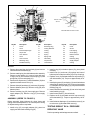
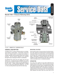
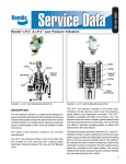
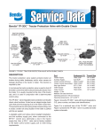
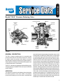
SD-03-3520
®
Bendix® RV-4™ Pressure Reducing Valve
EXHAUST PASSAGE
CONTROL
PORT
(PLUGGED)
SUPPLY
PORT
EXHAUST
CONTROL
PISTON
VALVE
SPRING
EXHAUST
CONTROL
PORT
(PLUGGED)
SUPPLY
PORT
DELIVERY
PORT (2)
MOUNTING
HOLE (2)
BALANCE
PISTON
DELIVERY (2)
BALANCE
PISTON
SPRINGS
SPRING
SHIMS
FIGURE 1
GENERAL DESCRIPTION
The RV-4™ pressure reducing valve is a normally open
pressure control device. The function of the RV-4™ valve is
to reduce system air pressure and maintain a constant
specified pre-set pressure below that of system pressure.
Various pressure settings can be obtained through the use
of springs and shims in combination.
The RV-4™ valve has one supply port and two delivery ports.
A single pipe plug is installed in the control port and should
remain in place.
OPERATION
The spring force exerted on the balance piston determines
the delivery pressure of the valve. With no air pressure
present at the supply port, the inlet valve is unseated and
open while the exhaust passage through the center of the
control piston is sealed by the exhaust valve. Compressed
air entering the supply port flows past the open inlet valve,
around the balance piston and out the two delivery ports.
When air pressure on the balance piston overcomes spring
force, the piston moves and the valve spring forces the inlet
valve on its seat, closing off the supply of air. The exhaust
remains closed. If air pressure in the delivery line drops,
spring force under the balance piston overcomes air
pressure. Subsequent piston movement will unseat the inlet
valve allowing additional air pressure into the delivery lines.
If pressure in the delivery lines exceeds the pressure setting
of the valve, the force exerted by the air pressure will be
greater than the spring force. The balance piston will move
away from the exhaust valve, permitting air to flow past the
exhaust valve, through the hollow piston stem and out the
exhaust port. The inlet valve will remain closed.
1
PREVENTIVE MAINTENANCE
Important: Review the Bendix Warranty Policy before
performing any intrusive maintenance procedures. A warranty
may be voided if intrusive maintenance is performed during
the warranty period.
4.
No two vehicles operate under identical conditions, as a
result, maintenance intervals may vary. Experience is a
valuable guide in determining the best maintenance interval
for air brake system components. At a minimum, the RV-4™
valve should be inspected every 6 months or 1500 operating
hours, whichever comes first, for proper operation. Should
the RV-4™ valve not meet the elements of the operational
tests noted in this document, further investigation and service
of the valve may be required.
5.
OPERATING & LEAKAGE TESTS
7.
6.
OPERATING
Connect an accurate test gauge in the supply and delivery
lines of the RV-4™ valve. Make certain that supply air
pressure is at the vehicle manufacturers recommended level.
Delivery pressure should be within plus or minus 5 p.s.i. of
the delivery pressure specified for the RV-4™ valve. If not,
the valve should be repaired or replaced. If the valve meets
this operating test, proceed to the leakage tests. Do not
remove the gauges at this time.
8.
9.
LEAKAGE
With supply pressure at the level recommended by the vehicle
manufacturer, apply a soap solution to the 1/4" N.P.T. plug
in the control port, around the supply port and to the exhaust.
Leakage should not exceed a 1" diameter bubble in 3
seconds (175 SCCM). If leakage is excessive, the valve
should be repaired or replaced and the operating and leakage
tests performed at the time of repair or replacement. Proceed
to the “Removal and Installation” instructions. This concludes
the operation and leakage tests and the test gauges should
be removed.
WARNING! PLEASE READ AND FOLLOW
THESE INSTRUCTIONS TO AVOID
PERSONAL INJURY OR DEATH:
When working on or around a vehicle, the following
general precautions should be observed at all times.
1. Park the vehicle on a level surface, apply the
parking brakes, and always block the wheels.
Always wear safety glasses.
2. Stop the engine and remove ignition key when
working under or around the vehicle. When
working in the engine compartment, the engine
should be shut off and the ignition key should be
removed. Where circumstances require that the
engine be in operation, EXTREME CAUTION should
be used to prevent personal injury resulting from
contact with moving, rotating, leaking, heated or
electrically charged components.
3. Do not attempt to install, remove, disassemble or
assemble a component until you have read and
2
10.
thoroughly understand the recommended
procedures. Use only the proper tools and observe
all precautions pertaining to use of those tools.
If the work is being performed on the vehicle’s air
brake system, or any auxiliary pressurized air
systems, make certain to drain the air pressure from
all reservoirs before beginning ANY work on the
vehicle. If the vehicle is equipped with an AD-IS™
air dryer system or a dryer reservoir module, be
sure to drain the purge reservoir.
Following the vehicle manufacturer’s
recommended procedures, deactivate the
electrical system in a manner that safely removes
all electrical power from the vehicle.
Never exceed manufacturer’s recommended
pressures.
Never connect or disconnect a hose or line
containing pressure; it may whip. Never remove a
component or plug unless you are certain all
system pressure has been depleted.
Use only genuine Bendix® replacement parts,
components and kits. Replacement hardware,
tubing, hose, fittings, etc. must be of equivalent
size, type and strength as original equipment and
be designed specifically for such applications and
systems.
Components with stripped threads or damaged
parts should be replaced rather than repaired. Do
not attempt repairs requiring machining or welding
unless specifically stated and approved by the
vehicle and component manufacturer.
Prior to returning the vehicle to service, make
certain all components and systems are restored
to their proper operating condition.
REMOVAL & INSTALLATION
REMOVAL
1. Hold the vehicle on a level surface by means other than
the air brakes.
2. Remove all air pressure from all reservoirs.
3. Identify, mark and then disconnect all air lines
attached to the valve.
4. Remove the valve.
INSTALLATION
1. Inspect and clean all air lines that connect to the valve.
2. Clean the vehicle valve mounting area and mount the
valve.
3. Reconnect the air lines according to the identification
marks made during removal.
DISASSEMBLY (Refer to Figure 2)
1. Remove exhaust cover screw (1), exhaust cover (2), and
exhaust diaphragm (3).
2. Remove four cap screws (4) with lockwashers (5) and
cover (6).
3. Remove control piston (7).
1
7
2
3
6
4
5
26
10
8
SUPPLY PORT
3/8” P.T.
9
12 & 13
25
27
11
14
SECTION VIEW OF SUPPLY PORT
15
16
23
24
22
21
20
18
17
19
Key No.
1
Description
Screw
Key No.
10
Description
Retaining Ring
Key No.
19
Description
Cover
2
3
Cover
Exhaust Diaphragm
11
12
O-Ring Retainer
O-Ring
20
21
Shims
Inner Spring
4
5
Cap Screw
Lock Washer
13
14
O-Ring
Spring
22
23
Outer Spring
Balance Piston
6
7
Cover
Control Piston
15
16
Spring Seat
Valve Body
24
25
O-Ring
Retaining Ring
8
9
Retaining Ring
Inlet/Exhaust Assy.
17
18
Cap Screws
Lockwashers
26
27
Supply Adapter
O-Ring
FIGURE 2
4. Remove large retaining ring from body (8) and remove
inlet/exhaust valve assembly (9).
5. Remove retaining ring from inlet/exhaust valve assembly.
Remove o-ring retainer (11), remove inner and outer
o-rings (12 & 13) from retainer. Remove spring (14) and
spring seat (15) from valve body (16).
6. Remove four cap screws (17) with lockwashers (18) from
opposite end and remove cover (19).
7. Remove shims (20) and inner (21) and outer (22) springs.
8. Remove balance piston (23). Remove o-ring (24) from
balance piston.
9. Remove retaining ring (25) from supply port. Remove
supply adapter (26). Remove o-ring (27) from supply
adapter.
ASSEMBLY (REFER TO FIGURE 2)
Before assembly, lightly lubricate all o-rings, bores and
mating surfaces with (Bendix Pc. No. 291126) Dow Coming
55-M pneumatic grease or equivalent.
1. Install o-ring (27) on supply adapter (26), place into
supply port and install retaining ring (25).
2. Install o-ring (24) on balance piston (23), place piston
into body.
3. Install inner (21) and outer (22) springs into base of
balance piston and place shims (20) on top of springs.
4. Replace cover (19) and attach with four cap screws (17)
with lockwashers (18). Torque to approximately 45 in.
lbs.
5. Install spring seat (15) and spring (14) onto inlet/exhaust
valve body (9). Install o-rings (12 & 13) onto o-ring retainer
(11) and place on top of spring (14), compress and install
retaining ring (10).
6. Install inlet/exhaust assembly (9) into valve body and
install retaining ring (8).
7. Install control piston (7) into valve body.
8. Replace cover (6) and attach with four cap screws (4)
and lockwashers (5). Torque to approximately 100 in.
lbs.
9. Install exhaust diaphragm (3) and exhaust cover (2) on
to valve cover (6) and attach with screw (1).
TESTING REBUILT RV-4™ PRESSURE
REDUCING VALVE
Perform operating and leakage tests as outlined.
3
4
BW1588 © 2004 Bendix Commercial Vehicle Systems LLC. All rights reserved. 4/2004 Printed in U.S.A.