1
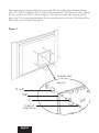
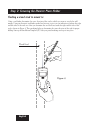
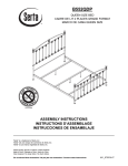
Introduction
Congratulations on your decision to mount your TV with a TV Wall Mounting Kit For Dummies. The
enclosed mounting bracket was engineered and designed by Bell’O International Corporation using the
latest computer-aided design and stress-analysis software to ensure safety and durability when installed
according to the instructions. It has been further tested and Listed by Underwriters Laboratories.
About This Manual
Mounting your TV on the wall can seem like an overwhelming task. This handy For Dummies® guide takes you
through the process step-by-step to ensure the proper installation of your mount. Before starting this project, be
sure to read the entire instruction manual and watch the included installation DVD for a complete
demonstration. If at any time you are unclear about the directions and believe you need further assistance,
contact the Bell’O® installation experts at 888-779-7781 from 9am – 5pm EST.
Icons Used in This Book
Don’t be alarmed by the bomb in the icon. We just want to
get your attention because making an error could be costly.
This is not really very technical stuff, just some details you
need to really pay attention to.
Foolish Assumptions
Although our easy-to-install mounts and instructions simplify the process, mounting your TV still requires
great care. We assume you’re someone who, at minimum, has done odd jobs around the house and has
some basic tools. You don’t need to be a master carpenter or electrician to install this mount. With that
said, if at any time you feel that you are uncertain or uncomfortable with doing the installation yourself,
don’t hesitate to call on a handyman or professional contractor/installer.
English
Precautions!
• This mounting bracket was designed to be installed and utilized ONLY as specified
in this manual. Bell’O International Corporation will not be responsible for failure
to assemble as directed or for the improper assembly, use, or handling of this
product.
• Improper installation of this product may cause damage or serious injury.
Bell'O International Corporation cannot be liable for direct or indirect damage or
injury caused by incorrect mounting, incorrect use, or incorrect assembly.
• If the mounting bracket will be attached to any structure other than those
specified in this manual, only a licensed professional contractor/installer should
perform this installation. The supporting structure must support, at minimum, four
times the combined weight of the mounting bracket and TV. It is the responsibility
and liability of the installer to ensure the suitability of the supporting structure.
• This product should NEVER be mounted to metal framing studs.
• Check carefully to ensure that there are no missing or damaged parts.
Never use defective parts. If any parts are damaged or missing, call Bell'O
International Corporation at 888-779-7781 and parts will be shipped directly to
purchaser. Please contact Bell’O International Corp. before attempting to return
products to the point of purchase.
• Specifications are subject to change without notice.
• The maximum weight of your television cannot exceed the maximum weight rating of
your mount or any attached Bell'O® UL listed adapters sold separately, whichever is
lower.
NEVER exceed the maximum load capacity of:
TV Wall Mount 8160: 65 lbs (30 kg)
English
TV Wall Mount 8165: 50 lbs (23 kg)
Parts Included in This Kit
(8165)
world’s
sibly the install!
Quite posmounts to
easiest
ide for
tion Gu
it
Installa Mounting K
ll
TV Wa
ep guide for
0 Mount
For 816
ing Bra
cket
by-st Video for
l
A stepation
Install
your flat pane
mounting
easily! ing Kits
Mount
Walland
TV safely
Bell’O TV
ary 2007 Bell'O
© Janu
Video: 701
on
or
dis
n
utio
trib
w
out
with
ritten
ission
perm
O
from Bell’
International Corp. All des
igns an
d ima
ges
are
prop
erty
of B
ell’
hange without notice.
bject to c
are su
ding
pen
tent
r pa
do
e
ent
pat
re
sa
ign
es
ll d
A
p.
OI
nte
rna
ti
on
a
lC
or
English
ti
uc
rod
ep
(SS) M4 x 12mm
Security Screw, Quantity: 2
rr
(F) M4/M5 Washer,
Quantity: 4
re
no
t fo
(E) M4/M5 Long
Spacer, Quantity: 4
an
da
(D) M4/M5 Short
Spacer, Quantity: 4
ted
(H) M5 x 22mm
Screw, Quantity: 4
righ
(G) M5 x 12mm
Screw, Quantity: 4
opy
(B) M4 x 22mm TV
Mounting Screw, Quantity: 4
ec
(A) M4 x 12mm TV
Mounting Screw, Quantity: 4
for
A step-by-step guide
panel
mounting your flat
TV safely and easily!
disc
ar
(MP) Monitor Plate
Quantity: 1
of th
is
(EA) Extension Arm
Quantity: 1
tents
, and
For Dummies,
Wiley, the Wiley logo,
logo, and
the Dummies Man
or registered
related trademarks
Wiley & Sons, Inc.
trademarks of John
Used by license.
and/or its affiliates.
Corp.
Bell’O International
711 Ginesi Drive
NJ 07751
Morganville,
International Corp
oration
. Con
(8160)
(IG) Installation Guide
& DVD, Quantity: 1 each
(C) M4 x 30mm TV
Mounting Screw, Quantity: 4
(I) M5 x 30mm Screw,
Quantity: 4
(IT) Installation
Template, Quantity: 1
Parts Included in This Kit (continued)
(T) #14 X 64mm Lag Bolt, Quantity: 2
(Y) Allen Key Tool, Quantity: 1
(Z) Plastic Finishing
Caps, Quantity: 2
(U) TOGGLER brand AF8
ALLIGATOR® Anchor, Quantity: 2
®
(WT) Wire Management
Ties, Quantity: 6
TOGGLER® brand ALLIGATOR® SOLID-WALL ANCHORS are patented under one or more of US Patent numbers 5,161,296 and 5,938,385; and foreign
counterparts thereof and of 4,752,170. Other patents pending. TOGGLER and ALLIGATOR are worldwide registered trademarks of Mechanical Plastics Corp.
Tools You Will Need
Phillips-head
Screwdriver
Stud Finder
Tape Measure
English
Drill
Drill Bit
Wood 5/32" (4mm)
or Masonry 5/16" (8mm)
Masking Tape
Level
Pencil
Getting ready to hang the TV
Figure 1
The Monitor Plate (MP) was shipped pre-installed to the Extension Arm
(EA). Before you begin, remove the two Security Screws (SS) as shown in
Figure 1 and separate the two components. Do not throw out the security
screws because you will need them later in the installation process.
SS
Select the location where you want to mount the TV. Clear the area of all
furniture and electronics. You will need some elbow room to mount the
TV. You also want to make sure that your electronic devices are unplugged,
covered, and out of way because you are about to start drilling holes, and
that is likely to make dust. You will also need to leave space that you can
use to mount the monitor plate onto the TV.
Your TV may have come with a stand installed. If it did, it is okay to
leave it on for now as long as it does not interfere with the monitor plate
installation. If not, you need to determine the best way to hold or rest your TV safely so
you can attach the monitor plate. Placing the TV face-down can damage the fragile screen
or decorative frame. You may want to get a friend to assist you in holding the TV. If you are
uncertain of the safest way to do this, call the TV manufacturer for advice.
Step 1: Attaching the Monitor Plate
Your TV owner’s manual generally explains where the mounting location is on the TV. There are
several typical mounting configurations for this size bracket. The mounting hole distances are
measured in millimeters per the VESA (Video Electronics Standards Association) specifications.
Table 1 lists the inch and millimeter equivalents just in case you have to measure them.
Use a tape measure to check the distances between the horizontal and vertical mounting holes. If your
mounting hole configuration is a Standard for this mount, as listed in Table 1, you’re ready for the next
step. If your hole configuration requires our For Dummies Adapter #8190 or other UL Listed adapters
intended to be used with this mount (sold separately, visit www.BellO.com for other options), please refer
to the instructions with that adapter for connecting the adapter to the monitor plate.
Table 1: Standard Monitor Mounting Configurations
Standard
Standard
Adapter 8190
Adapter 8190
Adapter 8190
English
Who is VESA?
The Video Electronics Standards Association is an international nonprofit organization representing
hardware, software, PC, display, and component manufacturers, cable and telephone companies, and
service providers. VESA supports and sets industry-wide interface standards for the PC, workstation, and
computing environments.
Choosing which screws to use
You’re probably wondering why so many screws came with this mount. The screw sizes follow the
standards set up by VESA for each mounting configuration.
Most monitors have the mounting holes flush with the back of the monitor. If yours is like this, use the
short 12mm TV Mounting Screws (A or G) as shown in Figure 2. Make sure that the Washers (F) are
placed between the screw and the Monitor Plate (MP). Don’t place the washers between the monitor
plate and the TV.
Don’t use screws that are too long because they will not fully seat in the holes and can
permanently damage the TV or mounting holes and cause the monitor to come loose.
Figure 2
DETAILED VIEW
Back of TV
MP
F
A or G
English
Some monitors have mounting holes that are recessed. This kit includes longer Mounting Screws
(Parts B, C, H & I) and Spacers (Parts D & E) for this configuration. The spacers are used to take up
the space in the recessed hole as shown in Figure 3. The spacer you select must stick out past the
back of the TV to ensure proper mounting. You don’t want the spacer to be loose. The Monitor Plate
(MP) needs to rest securely on the spacers.
Figure 3
DETAILED VIEW
Back of TV
D or E
MP
F
Selected
Long Screw
English
Step 2: Securing the Monitor Plate Holder
Finding a wood stud to mount to
Using a stud finder, determine the exact location of the stud to which you want to attach the wall
mount. Using an electronic stud finder works best because it gives you an indication of where the right
and left sides of the stud are. After you determine the stud location, mark the right and left side of the
stud as shown in Figure 4. These markings help you determine the center location of the stud for proper
drilling. Line up the Installation Template (IT) with your pencil markings and tape it into place.
Wood Stud
Figure 4
English
Determining the location of the TV
After the Monitor Plate (MP) has been mounted to the TV, you can now measure the distance from
the bracket holes to the top and bottom of the TV to help determine the desired height of the TV
on your wall. The reason that you need to take these measurements is because many monitors do not
have the mounting location centered on the back of the monitor. To determine the exact height you
want to mount the brackets, use the convenient Installation Template (IT) rather than holding the TV
in place while you do all this measuring. Always make sure to use a level when placing the template.
Measure from the floor up as shown in Figure 5, and using a pencil, make small marks on the wall to
help you determine the desired TV height.
Figure 5
Desired Position of TV
Wood
Studs
IT
16
Inches
(406mm)
English
Height to bottom of TV
Level
Using the Installation Template
The Installation Template (IT) included in this kit helps you select the correct positions for drilling
the holes for the TV mounting. Figure 6 shows what the holes on the template represent.
Figure 6
INSTALLATION TEMPLATE
GABARIT DE POSE
PLANTILLA DE INSTALACIÓN
For Models: 8140, 8160, 8165 & 8170
Pour les Supportes : 8140, 8160, 8165 et 8170
Para Soportes: 8140, 8160, 8165 y 8170
CAREFULLY FOLLOW DIRECTIONS
IN YOUR MANUAL AND/OR DVD
VEILLEZ À BIEN SUIVRE LES INSTRUCTIONS
DU MANUEL ET/OU DU DVD
a
DRILL HOLE “a”
SIGA DETENIDAMENTE LAS INSTRUCCIONES
DE SU MANUAL Y/O DVD
MOUNTING TO A WOOD STUD:
2
Centrez le gabarit de pose sur le montant et alignez les points de
perçage « a » et « b » sur les repères au crayon. Utilisez un niveau
pour vérifier que le gabarit est droit.
Check Level Line
1
À l'aide d'un détecteur de montant, déterminez l'emplacement
des bords du montant et marquez-les au crayon comme
indiqué dans le Guide de pose et/ou le DVD.
Revise la línea de nivel
Ligne de Niveau
POSE SUR UN MONTANT EN BOIS :
(VOIR LES INSTRUCTIONS DE POSE SUR MAÇONNERIE DANS LE MANUEL)
Ligne de Niveau
3
Carefully drill holes through points “a” and “b” using the
proper drill bit.
Check Level Line
2
Center Installation Template over stud, using windows to
view pencil marks. Use a level to ensure template is straight.
Use window to view stud edge markings
Les repères de bord de montant doivent être visibles à travers la fenêtre
Utilice la ventana para ver las marcas del borde del montante
1
Using a stud finder, locate the edges of wall stud and mark
stud edges with a pencil as shown in the Installation Guide
and/or DVD.
Revise la línea de nivel
(SEE INSTALLATION GUIDE FOR MASONRY INSTALLATIONS)
3
Percez avec soin à travers les points « a » et « b » avec le
foret qui convient.
b
DRILL HOLE “b”
INSTALACIÓN EN UN MONTANTE DE MADERA:
(VER EL MANUAL DE INSTALACIÓN PARA INSTALACIONES DE MAMPOSTERÍA)
2
Centre la plantilla de instalación sobre el montante, alinee los
puntos de perforación “a” y “b” con las marcas de lápiz. Utilice un
nivel para asegurarse de que la plantilla esté derecha.
3
Perfore cuidadosamente a través de los puntos “a” y “b” con
una broca adecuada.
Outer Edge of Stud
Bord extérieur du montant
Borde externo del montante
Con un localizador de montantes, localice los bordes del montante
de pared y márquelos con un lápiz como se muestra en el manual
de instalación y/o DVD.
Outer Edge of Stud
Bord extérieur du montant
Borde externo del montante
1
You must be careful to accurately drill the holes or else the screws may
not line up with the holes in your Extension Arm (EA).
English
When mounting to a wood stud
Line up the Installation Template (IT) with the stud markings to ensure the proper location for your drill
holes. After you have the position selected, tape the template in place securely on the wall with masking
tape so that you don’t damage the wall surface. Use a level to double check that the screw holes will line
up vertically as shown in Figure 7. Drill two holes 2.5" (64mm) deep using a 5/32" (or 4mm) size drill bit
in the “a” and “b” locations noted on the Installation Template.
When you have prepared the holes for mounting the Extension Arm (EA), place the extension arm over
the holes and screw in the two Lag Bolts (T). Leave some “wiggle” room so that you can make any
fine adjustments, if necessary. After making sure the extension arm is level, tighten all of the lag
bolts completely.
Next insert the plastic Finishing Caps (Z) into the holes in the Extension Arm (EA) to cover up the Lag
Bolts (T).
Figure 7
Supporting
Stud
EA
Wall
T
Z
Tighten mounting screws so that the Extension Arm (EA) is firmly attached to the wall, but
don’t over-tighten! The mounting screws and/or the supporting surface can become damaged,
which greatly reduces their holding ability. Final tightening of the mounting screws should
always be done by hand, with a Phillips-head screwdriver or ratchet wrench.
English
When mounting to solid concrete or cinder block
This kit includes the TOGGLER® brand ALLIGATOR®
Anchors (U) for mounting in concrete walls or cinder
block. These patented anchors are the finest solid wall
anchors on the market and offer excellent holding
ability when properly installed.
After you have determined your desired TV
location, tape the Installation Template (IT) in
place securely on the wall with masking tape.
Figure 8
IT
Use a level to double check that the screw
holes line up vertically as shown in Figure 8.
Carefully drill two holes using a 5/16" (or
8mm) masonry drill bit in the “a” and “b”
locations noted on the Installation Template.
Each hole should be at least 3" (76mm) deep.
Concrete Block Wall
Do not drill into mortar joints! Mortar joints are in between the concrete blocks where the
cement is. These joints are typically not strong enough to hold heavy loads. You need to
drill the holes at least one inch from the joint to provide adequate strength. Use a
standard drill with a new masonry drill bit to drill the holes. Do not use a hammer drill
because it can damage the hole or break out the back of the concrete wall which will
not give adequate support to the anchor.
Because drilling an accurate and clean hole is essential to securing your mount, be sure
to use a new drill bit. An old drill bit can not only make an uneven hole, it can also
break out the back of the concrete block which can diminish the holding ability of the
anchor.
English
After the holes are drilled, remove the template and place two ALLIGATOR® Anchors (U) into the
concrete wall as shown in Figure 9.
Figure 9
U
After you have prepared the two holes for mounting the Extension Arm (EA), install the extension
arm by inserting the two Lag Bolts (T) through the mount and into the holes (See Figures 7 and
10). After checking that the extension arm is level, tighten both lag bolts fully, but be careful not to
over-tighten.
Figure 10
T
3" (76mm) minimum
hole depth
U
EA
English
Concrete
Step 3: Mounting the TV
Getting the mount ready for attaching your TV
Tighten the “tilt” and “pan” knobs in the straight position using the supplied Allen Key Tool (Y) as
shown in Figure 11. This step makes your mount stable and easy to assemble.
TILT KNOB
Figure 11
Y
PAN KNOBS
Don’t forget those wires!
If your audio, video, and power cables will not be accessible after you mount the TV, you
need to make those connections now. Before doing this, however, make sure all TV and
component power cords are not plugged into any electrical outlets and your audio and
video equipment is turned off. Make sure you leave enough slack so you can install the
mount without any interference.
English
Mounting the TV
Figure 12
When you’re ready to put the Monitor
Plate (MP) onto the Extension Arm (EA),
get a friend or an assistant to help you lift
the TV and guide the monitor plate onto
the extension arm as shown in Figure 12.
MP
After you’re confident that the TV with
the Monitor Plate (MP) is properly seated
into the Extension Arm (EA), you need to
tighten the Security Screws (SS) using a
Phillips-head screwdriver as shown in
Figure 13. Because your TV is already
attached to the extension arm, you need to
work from above and behind the monitor to
do this.
EA
Figure 13
(View from Rear of TV)
SS
EA
English
After the TV is
installed, carefully try
to lift it off to make
sure it is secure.
If it has been correctly
installed, the TV
should not move.
Using the wire management feature
Your TV Wall Mounting Kit For Dummies was designed with a unique feature which helps you
manage all of your A/V wires and cables neatly and effortlessly. To use this feature, remove the Wire
Management Plate from the bottom of the Extension Arm (EA) and wrap some of the Wire
Management Ties (WT) around both the plate and your A/V cables, as shown in Figure 14. Pull the
ties tight and re-attach the plate to the bottom of the extension arm. To maintain a neat look, make
sure that the loose ends of the ties are tucked inside the extension arm before tightening the two
screws in the plate with a Phillips-head screwdriver.
Figure 14
[View from underside of Extension Arm (EA)]
Wire
Management
Plate
English
Wire
Management
Ties (WT)
A/V Cables
Adjusting your mount
After your TV is installed, you can adjust the tilt and horizontal position. The tilt knob carries the
weight of the TV and must be tightened with the supplied Allen Key Tool (Y) after the desired position
of the monitor is achieved. Tighten the tilt knob until the TV is firmly locked in position. Refer again
to Figure 11 for information on locating each of these knobs.
Do not loosen the screw on the opposite side (see Figure 15) because
it holds the tilt assembly together.
Figure 15
Figure 16
DO NOT
LOOSEN
SCREW
ADJUST KNOB
FROM THIS
SIDE ONLY
If you plan to adjust the position of your TV regularly, you can tighten the horizontal pan
knob by hand (see Figure 16). To keep it in a permanently locked position, however, you need
to tighten it with the supplied Allen key. Under no circumstances should you completely loosen
and/or remove any of these knobs.
English
Storing the Allen Key Tool
Don’t you hate it when you can’t find important tools that came with your product? Not a problem this
time — this For Dummies mounting bracket was designed with a special place to hold the Allen Key Tool
(Y) vertically in the wall plate, as shown in Figure 17. Insert the Allen key vertically into the wall
plate as shown below. Rotate the Allen key to the right to lock it in position. If you need to
remove the Allen key, simply rotate out of the locked position using a pen or other pointy object.
Figure 17
ALLEN KEY
HOLDER
DETAILED VIEW
Y
If you need to remove the TV
Flat screen TVs are very heavy and extremely fragile. Exercise caution when removing the
display from the mount to avoid equipment damage or personal injury.
If your cables are accessible, disconnect all power and A/V cables before removing the display from the
Extension Arm (EA). If cables are not accessible, have an assistant remove the cables as soon as the TV is
lifted off the extension arm. Also have the assisstant hold the TV as you loosen the Security Screws (SS)
from the Monitor Plate (MP) using a Phillips-head screwdriver. Lift the TV straight up until it becomes free
from the extension arm.
English
Visit www.BellO.com for more information on home theater furniture.
Visit www.Dummies.com for other great products, books, and free eTips!
Visit www.Paladin-Tools.com for information on the Cable & Satellite Installation Kit For Dummies.
Limited Lifetime Warranty
[Please note: You are responsible to inspect your mount thoroughly for missing or defective parts immediately after opening the
box. To receive replacement or missing part(s) under this Warranty, visit our website at www.bello.com or call our Customer
Service Department at 1-888-779-7781. Please have the model number, date code, part number(s) and your sales receipt or other
proof of purchase available for reference. We will ship you any necessary replacement parts without charge at our expense.]
This Bell’O International, Corp. (“Bell’O” or “we”) mounting product SKU # 8160 or 8165 (“Product”) is warranted for the life of the
Product only to the original purchaser and limited to the original installation (“Warranty”). Re-installation of the Product in a
different location or with a different monitor or peripheral voids this Warranty. This Warranty is only valid in the United States of
America.
We warrant to the original purchaser that the Product and all parts and components thereof are free of defects in material and
workmanship. “Defects”, as used in this Warranty, is defined as any imperfections that impair the use of the Product.
Our Warranty is expressly limited to replacement of mount parts and components. Bell’O will replace any part listed on the enclosed
mount parts sheet that is defective in material or workmanship only to the original owner within the limitations stated herein.
This Warranty applies only under conditions of normal use. The Product is not intended for outdoor use. This Warranty does not
cover: 1) defects caused by improper installation or disassembly; 2) defects caused by shipping (claims for damage during transit
to you should be made immediately by you directly to the transportation company); 3) defects occurring after purchase due to
modification, intentional damage, accident, misuse, abuse, negligence, natural disaster, abnormal mechanical or environmental
conditions, unauthorized disassembly, repair, modification or exposure to the elements; 4) cosmetic damage and 5) labor or
assembly costs.
This Warranty does not apply if the Product has been repackaged or resold as second-hand.
There are no warranties, express or implied, including without limitation merchantability or fitness for particular use, except as (i)
contained herein or (ii) required by applicable law in the state whose law governs. The substantive and procedural law of the State
of New Jersey shall govern this Warranty, absent controlling law imposing the law of another state in lieu thereof as governing law.
New Jersey Superior Court or the United States District Court for the District of New Jersey, as appropriate, shall retain exclusive
jurisdiction over enforcement of this Warranty and all subject matter hereof. All warranties of whatsoever derivation shall be limited
to the terms set forth herein, unless otherwise required by applicable law.
You shall not rely on manufacturers’, employees’ or representatives’ statements, whether oral or written, which neither modify this
Warranty nor are they part of either your purchase contract or this Warranty.
Except as provided herein, Bell’O has no liability or responsibility to you or any other person or entity with respect to any liability,
loss or damage caused directly or indirectly by use of the Product, including, but not limited to, any incidental or consequential
damages. Some states do not allow limitation on how long an implied warranty can last or the exclusion or limitation of incidental
or consequential damages. Therefore, the above limitations and exclusion may not apply to you.
This Warranty covers only repair or replacement for this mount as stated above.
This Warranty gives you specific legal rights. You may also have other rights, which vary from state to state.
English
Bell’O International Corporation
711 Ginesi Drive
Morganville, NJ 07751
www.bello.com
Wiley, le logo Wiley, Pour les Nuls, le logo du personnage Pour les Nuls et les marques de commerce
associées sont des marques déposées de John Wiley & Sons, Inc. et/ou de ses filiales.
Wiley, logotipo de Wiley, logotipo de la caricatura de Dummies y marcas registradas relacionadas o marcas
comerciales registradas de John Wiley & Sons, Inc. y/o sus empresas asociadas. Uso bajo licencia.