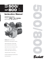
1
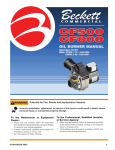
CF
Oil
Burner
Instruction Manual
ON/OFF Operation
Firing rate: CF500: 1.75 – 5.50 GPH
CF800: 3.00 – 8.00 GPH
Motor voltage: 120 / 60 Hz std.
Thank you for purchasing a
Beckett burner. With proper care and
regular maintenance, it will provide
years of trouble-free service. Please
take a few minutes to read the section
entitled “To the owner” inside this
manual. Then, keep the manual in a
safe place where it can be easily
located if needed by your professional
service technician.
500/800
500/
CF 800
MODEL
Instruction Manual – Model CF500/CF800 Oil Burner
Please . . . read this page first
Hazard definitions
The following will be used throughout this manual to bring attention to hazards and their risk factors, or to special information.
Denotes presence of a hazard which, if
ignored, will result in severe personal injury,
death or substantial property damage.
Denotes presence of a hazard which, if
ignored, could result in severe personal injury,
death or substantial property damage.
Denotes presence of a hazard which, if
ignored, could result in minor personal injury
or property damage.
Intended to bring special attention to
information, but not related to personal injury
or property damage.
To the owner —
Installation and adjustment of the burner
requires technical knowledge and the use of
combustion test instruments. Do not tamper
with the unit or controls. Call your qualified
service technician. Incorrect operation of the
burner could result in severe personal injury,
death or substantial property damage.
Have your equipment inspected and adjusted
at least annually by your qualified service
technician to assure continued proper
operation.
Never attempt to use gasoline in your heating
appliance or to store gasoline or combustible
materials near the heating equipment. This
could result in an explosion or fire, causing
severe personal injury, death or substantial
property damage.
To the installer —
Read all instructions before proceeding.
Follow all instructions completely. Failure to
follow these instructions could result in
equipment malfunction, causing severe
personal injury, death or substantial property
damage.
This equipment must be installed, adjusted
and started only by a qualified service
technician—an individual or agency, licensed
and experienced with all codes and
ordinances, who is responsible for the
installation and adjustment of the equipment.
The installation must comply with all local
codes and ordinances and with the National
Fire Protection Standard for Oil-Burning
Equipment, NFPA 31 (or CSA B139-M91).
2
To the owner —
Never burn garbage or refuse in your heating
appliance or try to light the burner by tossing
burning material into the appliance. This
could result in severe personal injury, death
or substantial property damage.
Never attempt to use crankcase or waste oil in
your heating appliance. This could damage
the fuel unit or heating equipment, resulting
in risk of severe personal injury, death or
substantial property damage.
Never restrict air openings on the burner or to
the room in which the appliance is located.
This could result in fire hazard or flue gas
leakage, causing severe personal injury, death
or substantial property damage.
To the installer —
Concealed damage - If you discover damage
to the burner or controls during unpacking,
notify the carrier at once and file the
appropriate claim.
Contacting Beckett for service information
or parts - Please record the burner serial number
(and have available when calling or writing).
You will find the serial number on the
Underwriters Laboratories label, located on
the left rear of the burner.
High altitude installations — Accepted
industry practice requires no derate of burner
capacity up to 2,000 feet above sea level. For
altitudes higher than 2,000 feet, derate burner
capacity 4% for each 1000 feet above sea
level.
Form 6104 BCF5-R0301
Instruction Manual – Model CF500/CF800 Oil Burner
Warranty
Contents
Beckett warrants its equipment to those who
have purchased it for resale, including your
dealer. If you have any problems with your
equipment or its installation, you should
contact your dealer for assistance.
Please . . . read this page first ................ 2
Pre-installation checklist........................... 4
Refer to warranty sheet in literature packet
included with burner for details.
Mount the burner .......................................... 6
Specifications
Fuels
#1 or #2 Fuel Oil
Firing range
CF500: 1.75 – 5.50 GPH
Connect fuel line(s) ...................................... 8
Wire the burner — R7184 ......................... 10
CF800: 3.00 – 8.00 GPH
Motor
1
/3 HP 3450 RPM
Wire the burner — R8184 (alternate) .. 11
120/60 hz standard
4.8 amps @ 120 VAC
Ignition Trans.
120V/10,000V
Housing
Cast aluminum
Fuel unit
100 - 200 PSIG
Oil nozzle
45° - 70° solid
Shipping wt.
55 lbs.
Prepare the burner for start-up ............. 12
Start the burner .......................................... 13
Maintenance and service......................... 14
Replacement parts ..................................... 15
Agency approvals
• Underwriters Laboratories has certified
this burner to comply with ANSI
Standard 296 and has listed it for use
with No. 1 or No. 2 fuel oil as specified
in ASTM D396. State and local
approvals appear on the burner rating
label.
• Certified by ULC.
• Approved by Commonwealth of
Massachusetts - State Fire Marshall.
• Accepted by N.Y.C. M.E.A.
• Other approvals may be available and
must be specified at time of order.
Before you begin . . .
The following resources will give you additional information
for your installation. We suggest that you consult these
resources whenever possible. Pay particular attention to the
appliance manufacturer’s instructions.
Appliance manufacturer’s instructions — Always follow
the appliance manufacturer’s instructions for burner
installation, equipment and set-up.
1–800–OIL–BURN — Beckett’s technical services hot-line.
www.beckettcorp.com — Beckett’s website.
Form 6104 BCF5-R0301
3
Instruction Manual – Model CF500/CF800 Oil Burner
Pre-installation checklist
❏ Combustion air supply
❏ Vent system
• The burner requires combustion air and ventilation air for
reliable operation. Assure that the building and/or combustion air openings comply with National Fire Protection
Standard for Oil-Burning Equipment, NFPA 31. For appliance/burner units in confined spaces, the room must have
an air opening near the top of the room plus one near the
floor, each with a free area at least one square inch per
1,000 Btu/hr input of all fuel burning equipment in the
room. For other conditions, refer to NFPA 31 (CSA B139M91 in Canada).
• If there is a risk of the space being under negative pressure
or of exhaust fans or other devices depleting available air
for combustion and ventilation, the appliance/burner
should be installed in an isolated room provided with outside combustion air.
• The flue gas venting system must be in good condition
and must comply with all applicable codes.
❏ Clearances
• Pedestal mounting assembly kit (recommended)
• With the burner installed in the appliance, there must be
adequate space in front of and on the sides of the burner to
allow access and operation. Verify that the clearance dimensions comply with all local codes and with the appliance manufacturer's recommendations.
• Oil nozzle, per Table 1 — Use only 45° to 70° solid pattern nozzles unless otherwise shown by appliance manufacturer.
Find the required firing rate in the 150 psig column (factory-set fuel unit pressure).
Select the corresponding nozzle from column 1 (Rated
gph @ 100 psig).
❏ Fuel supply
• The fuel supply piping and tank must provide #1 or #2
fuel oil at pressure or vacuum conditions suitable for the
fuel unit (oil pump) on the burner. Refer to fuel unit literature in the literature envelope in the burner carton to verify
allowable suction pressure.
The fuel unit is shipped without the by-pass
plug installed for CF500/CF800 ON/OFF
burners. You must install this plug on twopipe systems. DO NOT install the by-pass plug
in the fuel unit if connected to a one-pipe oil
system. Failure to comply could cause fuel
unit seal failure, oil leakage and potential fire
and injury hazard.
❏ Electrical supply
• Verify that the power connections available are correct for
the burner. All power must be supplied through fused disconnect switches.
❏ Verify burner components —
• Burner box, Model CF500 and CF800
• Air tube assembly (selected per following)
• Mounting flange kit
Table 1 - Nozzle capacities
Rated gph
@
100 psig
Pressure - pounds per square inch
140
150
1.75
2.07
2.14
2.00
2.37
2.45
2.25
2.66
2.74
2.50
2.96
3.06
If fuel supply is level with or higher than fuel unit —
2.75
3.24
3.37
• When the fuel unit is not required to lift the oil, the installation is usually suitable for either a one-pipe or two-pipe
oil system. The oil pressure at the inlet of the fuel unit must
not exceed 3 psig.
• See Figure 7 for one-pipe fuel supply installations. See
Figure 8 for two-pipe fuel supply installations.
3.00
3.55
3.68
3.50
4.13
4.29
4.00
4.70
4.90
4.50
5.30
5.51
If fuel supply is below the fuel unit —
5.00
5.90
6.13
• Use a two-pipe oil system when the fuel unit must lift the
oil more than 8 feet if burner is equipped with a B fuel unit.
The return line provided by the two-pipe system is needed
to purge the air from the fuel lines and minimize the
likelihood of air-related problems during operation.
5.50
6.50
6.74
6.00
7.10
7.33
6.50
7.65
7.96
4
Form 6104 BCF5-R0301
Instruction Manual – Model CF500/CF800 Oil Burner
❏ Verify firing rate
Figure 2 - Air tube mounting dimensions
• Refer to appliance manufacturer’s instructions (if available) for firing rate and nozzle selection. Otherwise, the
maximum recommended firing rate for the burner depends
on the length of the firing chamber and the distance from
the burner center to the chamber floor. Verify that the chamber dimensions are at least as large as the minimum values
given in Figure 1. If the appliance dimensions are smaller
than recommended, reduce the firing rate accordingly.
❏ Verify air tube
• The information in this section may be disregarded if the
air tube is supplied by the appliance manufacturer.
• Tube arrangements available:
CF500:
1.75 to 5.50 GPH
CF800:
A Tube — 3.00 to 7.00 GPH
B Tube — 5.00 to 8.00 GPH
• Maximum firing capacity depends on the firebox pressure.
Use Table 2 to verify the correct air tube for the firing rate
required.
• See Figure 2 to verify the correct air tube length and air
tube combination code.
Figure 1 - Min. Combustion chamber dimensions
Air tube
length
(Dimension T)
6.00"
8.00"
10.00"
14.00"
16.00"
17.00"
A.T.C. Codes
(A.T.C. = Air Tube Combination)
CF500
CF 60 KK
CF 80 KK
CF 100 KK
CF 140 KK
CF 160 KK
--
CF800
Tube A
CF 60 KH
CF 80 KH
CF 100 KH
CF 140 KH
-CF 170 KH
Tube B
CF 60 KJ
CF 80 KJ
CF 100 KJ
CF 140 KJ
-CF 170 KJ
Table 2 - Air tube capacity vs. firebox pressure
Firebox
pressure
(In. w.c.)
CF500
Tube KK
(GPH)
CF800
Tube KH
(GPH)
Tube KJ
(GPH)
No reserve air
Firing rate
GPH
1.75 to 3.00
4.00
5.00
6.00
7.00
8.00
Minimum dimensions (inches)
With damper
Without damper
A
L
A
L
7.5
18.0
8.0
19.0
8.0
21.0
9.5
23.0
9.0
23.0
10.5
30.0
10.0
28.0
11.5
40.0
11.0
34.0
12.0
46.0
14.0
38.0
14.0
51.0
Form 6104 BCF5-R0301
0.0
5.50
7.00
8.00
0.1
4.75
6.25
7.50
0.2
4.00
5.50
6.75
0.3
3.50
4.50
6.25
0.4
2.75
3.75
5.50
0.5
2.00
3.00
5.00
Note: The above ratings may vary 5% due to variations in
actual job conditions.
5
Instruction Manual – Model CF500/CF800 Oil Burner
Mount the burner
❏ Mount flange(s) on air tube
Figure 3 - Mount flange(s) on air tube
• This section does not apply to burners with welded flanges.
• Do not install air tube on burner.
• For non-pressure firing flange, refer to Figure 3: Install
gasket (item a ) and flange (item d ). Ignore the next
paragraph.
• For pressure-firing flange, refer to Figure 3: Slide gasket
(item a) onto the air tube, making sure the top of the air
tube is up. Pre-drill holes in the pressure firing plate (item b)
to match the appliance studs. Slide the pressure firing plate
(item b) and flange (item d) onto the air tube as shown.
Wrap ceramic fiber rope (item c) around the air tube and
press tightly into the inside diameter of the flange (item d).
• Slide the air tube (item e) into position in the appliance
front. Tighten the flange-mounting-stud nuts. Set the
insertion of the air tube so dimension G is ¼" nominal.
• Pitch the air tube at 2° from horizontal as shown and secure
the flange to the air tube.
Figure 4 - Nozzle and nozzle line assembly
❏ Mount air tube to burner
• Attach the air tube to the burner with the screws provided.
❏ Install nozzle
• See Figure 4. Install the oil nozzle in the nozzle adapter.
Use a ³⁄₄" open-end wrench to steady the nozzle adapter
and a ⁵⁄₈" open-end wrench to turn the nozzle. Tighten
securely but do not over-tighten.
• Check, and adjust if necessary, the critical dimensions
shown in the drawing. Verify that the oil tube assembly
and electrodes are in good condition, with no cracks or
damage.
6
Failure to properly set and maintain the
electrode and nozzle spacing dimensions can
cause incorrect burner ignition or poor
combustion. This could result in severe
personal injury, death or substantial property
damage.
Form 6104 BCF5-R0301
Instruction Manual – Model CF500/CF800 Oil Burner
❏ Install nozzle line assembly
Figure 5 - Nozzle line assembly in burner
• Insert the nozzle line assembly into the burner air tube.
• Slide the secondary adjusting plate (Figure 6, item f) completely to the left on the indicator adjusting plate (item e).
Finger-tighten acorn nut c to secure the two plates together.
Slide both plates completely to the right (Indicator plate
will read 0). Tighten fastener d.
• Install the spline nut on the end of the nozzle line, leaving
the nut loosely placed so the plates can be moved.
❏ Set dimension Z
• Loosen fastener c in Figure 6. Slide the nozzle line and
plate assembly until dimension Z in Figure 5 is:
CF500 — 19/16" ± 1/16"
Figure 6 - Adjusting plate assembly
CF800 — 13/4" ± 1/16"
When dimension Z (from end of air tube to flat area of front
face of head) is correctly set, tighten acorn nut c.
• Attach the oil line from the oil valve to the nozzle line end.
Tighten securely.
• Before proceeding, check dimension Z once again. Loosen
acorn nut c if necessary to reposition the nozzle line. Once
dimension Z is set, do not loosen acorn nut again. For the
setting of fastener d, refer to page 12.
❏ Insert burner
Legend
c
d
e
f
acorn nut
fastener
Indicator adjusting plate
Secondary adjusting plate
• Position the burner in the front of the appliance and loosely
tighten the nuts on the mounting studs. The burner should
be pitched downward 2° as shown in Figure 3.
Form 6104 BCF5-R0301
7
Instruction Manual – Model CF500/CF800 Oil Burner
Connect fuel line(s)
Install the oil lines using the following
guidelines. Failure to comply could lead to
equipment damage and present a risk of severe
personal injury, death or substantial property
damage due to leakage of oil and potential
fire hazard.
Use only flare fittings at joints and
connections. Never use compression fittings.
Install fittings only in accessible locations to
assure any leak will be detected.
Where joint sealing is needed, use only pipe
dope. Never use Teflon tape. Tape strands can
break free and damage the fuel unit.
Never use a one-pipe oil system with a lift in
excess of 8 feet with B fuel unit. On two-pipe
oil systems, verify that the suction line
vacuum does not exceed the fuel unit
manufacturer’s recommendation.
The fuel unit is shipped without the by-pass
plug installed for CF500/CF800 ON/OFF
burners. You must install this plug on twopipe systems. DO NOT install the by-pass plug
in the fuel unit if connected to a one-pipe oil
system. Failure to comply could cause fuel
unit seal failure, oil leakage and potential fire
and injury hazard.
❏ Fuel unit by-pass plug
• The CF500/CF800 burner is shipped without the by-pass
plug installed in the fuel unit.
• The by-pass plug must not be installed in the fuel unit for
one-pipe oil systems.
• You must install the by-pass plug if using on a two-pipe
oil system.
❏ Oil supply/return lines
• Install the oil tank and oil lines in accordance with all
applicable codes.
• Size the oil supply and return lines using the guidelines
given in the fuel unit literature included in the literature
envelope. Oil line flow rate will equal the burner rate for
one-pipe systems. For two-pipe systems, refer to Table 3
for the fuel unit gearset capacity - the rate at which fuel is
recirculated when connected to a two-pipe system. Size
two-pipe oil lines based on this flow rate.
• Use continuous lengths of heavy-wall copper tubing,
routed under the floor where possible. Do not attach fuel
lines to the appliance or to floor joists if possible. This will
reduce vibration and noise transmission problems.
• Install an oil filter sized to handle the fuel unit gearset flow
capacity (Table 3) for two-pipe systems. Size the filter for
the firing rate for one-pipe systems. Locate the filter immediately adjacent to the burner fuel unit.
• Install two high-quality shut-off valves in accessible locations on the oil supply line. Locate one valve close to the
tank. Locate the other valve close to the burner, upstream
of the fuel filter.
8
Form 6104 BCF5-R0301
Instruction Manual – Model CF500/CF800 Oil Burner
❏ Burner fuel flow
Figure 7 – One-pipe oil flow with “B” pump
• One-pipe systems – See Figure 7 for the fuel flow path.
• Oil supply connects to one of the fuel unit inlet ports.
• Two-pipe systems – See Figure 8 for the fuel flow paths
for two-pipe oil systems.
• Oil supply connects to one of the fuel unit inlet ports.
Oil return connects to the fuel unit return port. (Install
the by-pass plug in the fuel unit for two-pipe systems.)
Figure 8 – Two-pipe oil flow with “B” pump
• Nozzle pressure – The fuel unit nozzle port pressure is
factory set at 140 psig. Some original equipment manufacturer burner applications may call for a lower pressure to
obtain a required firing rate. Do not change this pressure
unless directed to do so by the appliance manufacturer.
Legend
Table 3 – Fuel unit gearset capacities
Fuel unit model number
Gearset capacity (GPH)
A2VA-7116
17
A2YA-7916
20
B2VA-8216
21
B2YA-8916
25
B2TA-8248
21
Form 6104 BCF5-R0301
a
b
c
d
Return port
Nozzle port
Oil valve
Nozzle & adapter
g Inlet port
k Return line to oil tank
p Air bleed valve
9
Instruction Manual – Model CF500/CF800 Oil Burner
Wire the burner — R7184
Install the burner and all wiring in accordance with the
National Electrical Code and all applicable local codes or
requirements.
Wire the burner in compliance with all instructions provided
by the appliance manufacturer. Verify operation of all controls
in accordance with the appliance manufacturer's guidelines.
See Figure 9a for a typical wiring diagram, with R7184 oil
primary, for reference purposes only.
Sequence of operation — typical
Do not by-pass any safety control.
By-passing a safety control could result in
severe personal injury, death or substantial
property damage.
Electrical shock hazard - can cause injury
or death. Disconnect power before installing
or servicing. Provide ground wiring to the
burner in accordance with the National
Electrical Code.
Figure 9a – Typical wiring
1. Standby — The burner is idle, waiting for a call for heat.
When a call for heat is initiated, there is a 2- to 6-second
delay while the control performs a safe start check.
2. Valve-on delay — As applicable, the ignition and motor
are turned on for a 15-second prepurge.
3. Trial for ignition (TFI) — The fuel valve is opened, as
applicable. A flame should be established within the 15second lockout time (30-second lockout time is available).
4. Lockout — If flame is not sensed by the end of the TFI,
the control shuts down on safety lockout and must be
manually reset. If the control locks out three times in a
row, the control enters restricted lockout. Call a qualified
service technician.
5. Ignition carryover — Once flame is established, the
ignition remains on for 10 seconds to ensure flame
stability. It then turns off.
6. Run — The burner runs until the call for heat is satisfied.
The burner is then sent to burner motor-off delay, as
applicable, or it is shut down and sent to standby.
7. Recycle — If the flame is lost while the burner is firing,
the control shuts down the burner, enters a 60-second
recycle delay, and then repeats the ignition steps
outlined above. If the flame is lost three times in a row,
the control locks out to prevent continuous cycling with
repetitious flame loss caused by poor combustion.
8. Burner motor-off delay — If applicable, the fuel valve is
closed and the burner motor is kept on for the selected
postpurge time before the control returns the burner to
standby.
1
Standby
2
Valve-on
delay
3
5
Trial for
ignition
10
Lockout
Ignition
carryover
8
Motor-off
delay
(postpurge)
4
Legend
7
6
Run
Recycle
FD
LM
OP
PR
CC
Fused disconnect, by others
Limit controls, by others
Operating controls, by others
Oil primary control, R7184 typical
Flame sensor, cad cell typical
TR
M1
S1
T-T
F-F
Ignition transformer
Burner motor
Oil valve
24-volt thermostat/limit terminals
Cad cell flame sensor terminals
Form 6104 BCF5-R0301
Instruction Manual – Model CF500/CF800 Oil Burner
Wire the burner — R8184 (alternate)
Install the burner and all wiring in accordance with the
National Electrical Code and all applicable local codes or
requirements.
Do not by-pass any safety control.
By-passing a safety control could result in
severe personal injury, death or substantial
property damage.
Wire the burner in compliance with all instructions provided
by the appliance manufacturer. Verify operation of all controls
in accordance with the appliance manufacturer's guidelines.
Electrical shock hazard - can cause injury
or death. Disconnect power before installing
or servicing. Provide ground wiring to the
burner in accordance with the National
Electrical Code.
See Figure 9b for an alternate wiring diagram, with R8184
oil primary, for reference purposes only.
Figure 9b – Alternate wiring R8184
Sequence of operation — typical
1. Standby — The burner is idle, waiting for a call for heat.
2. Trial for ignition (TFI) — The fuel valve is opened, as
applicable. A flame should be established within the 15second lockout time (30-second lockout time is available).
3. Lockout — If flame is not sensed by the end of the TFI,
the control shuts down on safety lockout and must be
manually reset.
• To reset the control after lockout, wait 2 to 3 minutes
after lockout to give the internal switch time to cool.
• Then push the reset button on the primary control,
allowing the burner to operate in normal sequence.
• Troubleshoot the reason for the flame sense failure.
4. Run — The burner runs until the call for heat is satisfied.
1
Standby
2
Trial for
ignition
3
Lockout
4
Run
Legend
FD
LM
OP
PR
CC
Form 6104 BCF5-R0301
Fused disconnect, by others
Limit controls, by others
Operating controls, by others
Oil primary control, R8184 typical
Flame sensor, cad cell typical
TR
M1
S1
T-T
F-F
Ignition transformer
Burner motor
Oil valve
24-volt thermostat/limit terminals
Cad cell flame sensor terminals
11
Instruction Manual – Model CF500/CF800 Oil Burner
Prepare the burner for start-up
Start-up checklist –
Verify the following
before attempting to start burner.
❏ Combustion air supply and venting have been inspected
and verified to be free of obstructions and installed in
accordance with all applicable codes.
❏ Oil nozzle has been selected correctly and securely installed
in the nozzle adapter.
❏ Fuel unit by-pass plug has not been installed for one-pipe
oil system.
By-pass plug has been installed for two-pipe oil system.
❏ Fuel connection to nozzle line assembly is secure.
❏ Dimension Z has been set per this instruction manual.
❏ Fuel supply line is correctly installed, the oil tank is
sufficiently filled, and shut-off valves are open.
❏ Burner is securely mounted in appliance, with pressure
firing plate and gasket installed for pressurized chamber
application.
❏ Appliance has been filled with water (boilers) and controls
have been operationally checked.
❏ Burner has been installed in accordance with appliance
manufacturer’s instructions (when available).
❏ Also refer to appliance manufacturer’s instructions (when
available) for start-up procedures.
❏ Z dimension
• Should be set per these instructions (see page 7). The acorn
nut (Figure 6, item c, page 7) should never be loosened
once the Z dimension is initially set.
❏ Initial head position
• The indicator plate assembly markings correspond to head
position settings.
• Loosen the fastener (Figure 6, item d, page 7) and slide
the indicator plate until the number on the plate corresponds to the initial head setting given in Table 4 for the
desired firing rate.
• When the head position has been set, tighten the fastener
and spline nut.
❏ Initial air settings
• Loosen the air band and shutter, and adjust to the settings
for the applicable firing rate shown in Table 5.
• These initial settings should be adequate for starting the
burner. Once the burner is in operation, the air settings will
12
be adjusted for best performance as discussed later in this
manual.
• Follow the procedures given later in this manual for finetuning the air settings.
❏ Set appliance limit controls
• Set the appliance limit controls in accordance with the
appliance manufacturer's recommendations.
❏ Prepare the fuel unit for air venting
• To vent air from one-pipe oil systems, attach a clear hose to
the vent plug on the fuel unit. Provide a container to catch
the oil. Loosen the vent plug.
• Vent the air as described under Start the burner, page 13,
when using the R7184 control.
Table 4 – Initial indicator adjustment plate settings
(head position)
Rate
GPH
Approximate head settings
CF500
CF800
Tube A
Tube B
0
--0
4
0
-5
1
-5
2
-6
4
3
6
4
4
-4
4
-6
5
--6
1.75
2.25
3.00
3.50
4.00
5.00
5.50
6.00
7.00
8.00
Table 5 – Initial air settings
Rate
GPH
1.75
2.25
3.00
3.50
4.00
5.00
5.50
6.00
7.00
8.00
Approximate air settings
CF500
CF800
Tube A
Tube B
Shutter
Band
Shutter
Band
Shutter
Band
1
2
10
10
10
10
10
----
0
0
1
2
3
5
10
----
--1
3
4
9
9
10
10
--
--0
0
0
0
5
3
8
--
-----8
9
10
10
10
-----2
4
3
5
10
Form 6104 BCF5-R0301
Instruction Manual – Model CF500/CF800 Oil Burner
Start the burner
Do not proceed unless all prior steps in this
manual have been completed. Failure to
comply could result in severe personal injury,
death or substantial property damage.
Do not attempt to start the burner when excess
oil has accumulated, when the appliance is
full of vapor or when the combustion chamber
is very hot. Do not attempt to re-establish
flame with the burner running if the flame
should be extinguished during start-up,
venting or adjustment. Allow the unit to cool
off and all vapors to dissipate before
attempting another start. Failure to comply
with these guidelines could cause an
explosion or fire, resulting in severe personal
injury, death or substantial property damage.
If control is not an R7184 refer to
manufacturer’s literature for specific
control.
Resetting from restricted lockout
• If the control locks out three times in a row without a
complete heat cycle between attempts, the lockout
becomes restricted. A qualified service technician
should be called to inspect the burner.
Disable function
• Any time the motor is running, press and hold the reset
button to disable the burner. The burner will remain off
as long as the button is held and will return to standby
when released.
Cad cell resistance check
• While the burner is firing, and after the ignition has been
turned off, press and release the reset button (hold ½second or less) to check the cad cell resistance. The LED
will flash 1 to 4 times, depending on the cad cell
resistance (see the table below). For proper operation, it
is important that the cad cell resistance is below 1600
Ohms.
❏ Starting the burner and venting air
LED flashes
Cad cell resistance
Priming the pump
1
0-400 Ohms
1. Initiate a call for heat.
2
400-800 Ohms
2. While the ignition is on, press and release the reset button
(hold ½-second or less). If the control has not locked out
since its most recent complete heat cycle, the lockout time
will be extended to 4 minutes (45 seconds in earlier units),
and the ignition will remain on the entire heat cycle.
3
800-1600 Ohms
4
more than 1600 Ohms
3. Bleed the pump until all froth and bubbles are purged. If
prime is not established within the extended lockout time,
the control will lock out. Press the reset button to reset the
control and return to step 2.
The reset button can be held for 30 seconds at
any time to reset the control’s lockout counter
to zero and send the control to standby.
4. Repeat steps 2 and 3, if needed, until the pump is fully
primed and the oil is free of bubbles. Then terminate the
call for heat, and the control will resume normal operation.
Form 6104 BCF5-R0301
LED Indicator key
LED
Status
On
Flame sensed
Off
Flame not sensed
Flashing
(½-second on, ½-second off)
Lockout/
Restricted lockout
Flashing
(2 seconds on, 2 seconds off)
Recycle
13
Instruction Manual – Model CF500/CF800 Oil Burner
Start the burner
continued
❏ Set air adjusting plate
1. Allow the burner to run until the appliance has warmed
sufficiently.
b. Increase the air to reduce CO2 by 2 percentage points
at a zero smoke level. (Increase O2 by 3 percentage
points at a zero smoke level.)
Example: Reduce CO2 from 13.5% to 11.5%, with zero
smoke (or increase O2 from 2.5% to 5.5%).
2. Visually check the flame. The flame should not be dark
orange or smoky.
If the flame appears to be smoking, increase the amount
of air by re-adjusting the air band to a higher number.
3. Once the appliance has warmed, the air setting can be
checked and adjusted.
4. Use combustion test instruments to adjust the burner.
a. Adjust the air until a trace of smoke is achieved with
CO2 level as high as possible (lowest possible O2).
Example: 13.5% CO2 (2.5% O2) with a trace of smoke.
c. This procedure provides a margin of reserve air to accommodate variable conditions.
5. Check the breech draft pressure against the appliance
manufacturer’s recommended setting (typically + 0.1"
W.C.).
6. If the breech pressure is higher or lower than recommended
level, adjust the appliance breech damper to achieve the
specified setting. Recheck the smoke and CO2 levels. Adjust burner air if necessary.
Maintenance and service
The burner must be serviced at least annually by a qualified service technician to assure continued reliable
operation. Operation and adjustment of the burner requires technical knowledge and the use of combustion test
instruments. Do not tamper with the burner or controls. Failure to comply could result in failure of the burner or
system, resulting in severe personal injury, death or substantial property damage.
Annual service
❏
Inspect combustion air and vent systems.
— by qualified service technician
❏
Replace oil filter.
Have the burner inspected, tested and started at least annually
by a qualified service technician. This annual test/inspection
should include at least the following:
❏
Oil motor (if not permanently lubricated).
❏
Replace oil nozzle.
❏
Clean burner and blower wheel (if needed to remove
lint or debris).
❏
Test ignition and combustion and verify air settings.
❏
Test oil supply line vacuum - verify that it is within
allowable range indicated in fuel unit literature.
❏
Check pump pressure to nozzle.
❏
Inspect fuel system (including tank, lines and all
connections).
14
Monthly maintenance
— by owner
❏
Observe combustion air openings and vent system for
integrity. Openings must be clean and free of obstructions.
❏
Check oil lines and fittings to verify there are no leaks.
❏
Observe burner ignition and performance to verify
smooth operation.
❏
Shut the system down if you observe abnormal or questionable operation. Call a qualified service agency for
professional inspection and service.
Form 6104 BCF5-R0301
Instruction Manual – Model CF500/CF800 Oil Burner
Replacement parts
Item
1
2
3
4
5
6
Part name
Air tube
Flange kit
Electrode assembly
Air shutter
Nozzle line assembly
Head assembly
7
8
10
11
12
17
20
21
Fuel lines
Air band
Adjusting plate assembly
Spline nut
Fuel pump
Coupling
Control
Ignitor
-22
23
Transformer
Motor
Blower wheel
24
Pedestal kits
Description
Refer to Figure 2, page 5
Refer to Figure 10, below
Part number
Specify
3215
Refer to Figure 2, page 5
CF500 — KK
CF800 — KH (Tube A)
CF800 — KJ (Tube B)
Specify lengths
51401U
51252P
51302P
3819
51286
3666
Refer to Table 3, page 9
2433
Specify
14,000 volt France
14,000 volt Allanson
13
/ HP
CF500 — 5 19/32" x 2 13/32"
CF800 — 6 5/16" x 2 3/8"
Extended
Standard
7440
7438
2289
21341U
21448U
21339U
5606
5685
Figure 10 – Adjustable mounting plates for CF500/CF800
Form 6104 BCF5-R0301
15
Instruction Manual – Model CF500/CF800 Oil Burner
U.S.A.: P. O. Box 1289 • Elyria, Ohio 44036 • 800-645-2876 • 440-327-1060 • FAX 440-327-1064
Canada: R. W. Beckett Canada, Ltd. • 430 Laird Road • Guelph, Ontario, N1G 3X7 • 800-665-6972 • FAX 519-763-5656
Form 6104 BCF5-R0301