1
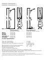
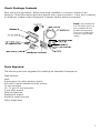
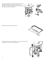
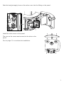
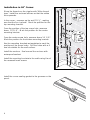
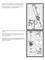
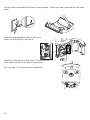
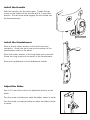
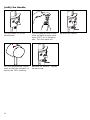
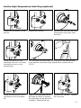
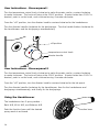
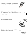
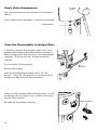
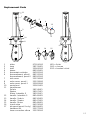
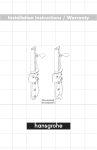
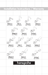
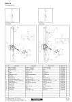
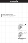
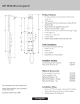
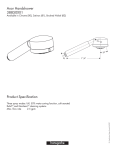
Installation Instructions / Warranty
Interaktiv
Showerpanel
Interaktiv Showerpanel I
Interaktiv Showerpanel II
Showerpanel I
Metro
Solaris
Stratos
Interaktiv S
Proaktiv*
Showerpanel II
handshower & bodyjets
handshower, bodyjets, tub spout
06572000
06549XX0
06564XX0
06893000
06964000
06573000
06550XX0
06565XX0
06894000
06971000
Product Specification
Flow rate of handshower
Flow rate of each bodyjet
Maximum flow rate of thermostatic mixing valve
2.5 gpm
1.0 gpm
8 gpm @ 45 psi
10 gpm @ 65 psi
120o – 140o F**
45 – 72 psi
Recommended incoming hot water temperature
Recommended incoming water pressure
Anodized aluminum body
Listed by Underwriters Laboratories
Backflow protection provided by check valve in handshower outlet.
The high temperature limit stop on the thermostatic mixing valve cartridge can be re-set to
comply with local plumbing codes -- see page 13.
*Proaktiv showerpanels are sold without trim. Proaktiv showerpanel trim kits are sold separately.
**Please know and follow all applicable local plumbing codes when setting the temperature on the water heater. In
Massachusetts, the water heater may be set no higher than 112oF.
2
Check Package Contents
Save time and aggravation. Before beginning installation, check the contents of this
package. Make sure that all parts are present and in good condition. If any part is missing
or damaged, please contact Hansgrohe Customer Service before proceeding.
Note: the handshower
and Techniflex hose are
not included with the
Proaktiv showerpanel.
They are included with
the trim kit (sold separately).
Tools Required
The following tools are suggested for installing the Interaktiv Showerpanel:
Tape measure
Level
Grease pencil or other marking device
Drill with 6 mm bit suitable for wall surface
10 mm nut driver
10, 11 and 19 mm wrenches
3 mm Allen wrench
Philips screwdriver
Waterproof sealant
Mallet (to install anchors)
Teflon thread tape
3
Roughing-in
This unit can be installed on a flat wall or in a 90o corner. Instructions for installation on a
flat wall begin on page 5. Go to page 8 if the panel is to be installed in a corner.
Ensure that you have a minimum 83” ceiling height from the standing
surface.
Stub out 1/2" NPT male nipples for the hot and cold water supplies at the locations shown
on the appropriate rough-in diagram. The nipples should extend 5/8" outside the surface
of the finished wall.
Install the wall surface and make the wall watertight before installing the panel. The panel
hangs on the finished wall. Seal the wall around the nipples with waterproof sealant.
Installation on a Flat Wall
4
Installation in 90o Corner
Installation -- Flat Wall
Wrap the threads on the supply nipples with Teflon thread
tape.
Install the enclosed elbows so that the outlets face
upwards.
Measure up the wall 78 ¾”, making sure that the line is
plumb. Mark the position for the top screw hole.
From the position of the top screw hole, measure down
35 3/8”. Mark the position for the center screw hole.
From the center screw hole, measure down 19 1/8”.
Mark the position for the bottom screw hole.
Use a 6 mm drill bit suitable for the wall surface. Drill the
three screw holes.
Install the anchors. Seal the wall around the anchors with
waterproof sealant.
Install the set screws in the top and bottom holes.
Use a 10 mm nut driver to attach a nut to the top set
screw.
Slide the panel over the top and bottom set screws.
Tighten the nut on the top set screw.
Install and tighten the nut on the bottom set screw.
Install one recessed head screw and the large washer on
the center hole. Tighten the screw.
5
Use the compression nuts and ferrules to connect
the supply hoses on the panel to the supply
elbows. Use two wrenches, as shown, to prevent
the supply hoses from twisting.
Attach the seals to the side covers.
Install the side covers. The pins on the covers must go into
the grooves on the sides of the panel.
6
Push the bodyjet supply hose on the valve cover into the fitting on the panel.
Install the valve cover on the panel.
The pins on the cover must connect to the slots on the
panel.
Turn to page 11 to continue the installation.
7
Installation in 90o Corner
Wrap the threads on the nipples with Teflon thread
tape. Install the enclosed elbows so that the outlets
face upwards.
In the corner, measure up the wall 78 ¾”, making
sure that the line is plumb. Mark the position for the
top mounting bracket.
From the position of the top screw hole, measure
down 35 3/8”. Mark the position for the center
mounting bracket.
From the center screw hole, measure down 19 1/8”.
Mark the position for the bottom mounting bracket.
Use the mounting brackets as templates to mark the
positions of the screw holes. Drill the holes with a 6
mm bit suitable for the wall surface.
Install the anchors. Seal around the anchors with
waterproof sealant.
Install the mounting brackets to the walls using five of
the recessed head screws.
Install the corner sealing gasket to the grooves on the
panel.
8
While a helper holds the panel, attach the supply
hoses to the elbows with the compression fittings.
Use two wrenches, as shown in the diagram, to
prevent the supply hoses from twisting.
Tighten the hex head cap screw on the top mounting
bracket.
Install and tighten the hex head cap screw on the
bottom mounting bracket through the hole in the
panel and tighten.
Install the hex head cap screw and large washer on
the center mounting bracket through the hole in the
panel and tighten.
9
Clip the side cover seals as shown in the diagram. Attach the side cover seals to the valve
cover.
Push the bodyjet supply hose on the valve
cover into the fitting on the panel.
Install the valve cover on the panel. The pins on the
cover must connect to the slots on the panel.
Turn to page 11 to continue the installation.
10
Install the Handle
Push the handle over the valve stem. Tighten the set
screw on the bottom of the handle with a 3 mm Allen
wrench. The set screw must engage the slot milled into
the thermoelement.
Install the Handshower
Place a black rubber washer in the short hose end
connector. Screw the short hose end connector to the
handshower outlet on the panel.
Place the screen washer in the long hose end connector.
Screw the long hose end connector to the handshower.
Place the handshower in the handshower holder.
Adjust the Slider
Use a 2.5 mm Allen wrench to adjust the tension on the
slider.
Turn the screw clockwise to make the slider easier to move.
Turn the screw counter-clockwise to make the slider harder
to move.
11
Justify the Handle
Turn the water on to the
handshower.
Turn the temperature control
knob so that the water measures 100oF on a thermometer. Turn the water off.
Turn the temperature control
knob so that the indicator is
next to the 100o marking.
Replace the handle. Tighten
the set screw.
12
Remove the handle.
Set the High Temperature Limit Stop (optional)
Remove the clip and the high
temperature limit stop from
the stem.
Loosen the set screw on the
handle.
Remove the handle.
Grasp the barrel on the
cartridge and turn it counterclockwise to turn on the
handshower.
Turn the stem until the water coming out of the handshower
is the desired maximum high temperature (usually about
110oF).
Grasp the barrel and turn it
clockwise to turn the water
off.
Reinstall the handle. Tighten
Replace the high temperature
the set screw.
limit stop so that it is against
the brass stop on the top of the
cartridge. Replace the clip.
13
User Instructions - Showerpanel I
Turn the temperature control knob clockwise to make the water cooler, counter-clockwise
to make it warmer. The knob will stop at the 100oF position. If water hotter than 100oF is
desired, push in on the knob, and continue turning it counter-clockwise.
From the “off” position, turn the diverter handle counter-clockwise for the handshower.
Turn the diverter handle clockwise for the bodysprays. Turn the handle further clockwise for
the handshower and the bodysprays simultaneously.
off position
temperature control knob
diverter handle
User Instructions - Showerpanel II
Turn the temperature control knob clockwise to make the water cooler, counter-clockwise
to make it warmer. The knob will stop at the 100oF position. If water hotter than 100oF is
desired, push in on the knob, and continue turning it counter-clockwise.
From the “off” position, turn the diverter handle counter-clockwise for the tub spout.
Turn the diverter handle clockwise for the handshower, then for the handshower and
bodysprays simultaneously, and finally for the bodysprays.
Using the Handshower
The handshower has 3 spray modes -Rainl AIR, Whirl AIR, and Balance AIR.
Push the function lever until the desired
spray mode is achieved.
14
function lever
Scale Removal
The Raindance Air 3-jet handshower incorporates the RubitTM
cleaning system. If scale deposits are noticed in the spray
channels, turn the water on lightly and rub the spray channels
with a finger or a sponge.
If scale deposits are noticed on the spray face, pour about
3/4” of a commercial scale remover, such as Lime-AwayTM or
CLRTM ,into a shallow dish. Dilute the remover according to the
label instructions.
Soak only the spray face in the solution for the amount of time
specified on the label.
Rinse the handshower with clear water.
Reinstall the handshower. Turn on the water and allow the
handshower to flush for at least one minute.
15
Check Valve Maintenance
The check valve should be removed and inspected
yearly.
If the check valve is damaged, it should be replaced.
check valve
Clean the Thermostatic Cartridge Filters
A possible cause of lost pressure, especially if the
pressure decreases as the temperature increases, is
debris clogging the filter screens on the thermostatic
cartridge. If this occurs, the screens should be
cleaned.
Turn the water off at the main.
Remove the handle.
Hold the thermoelement steady with a 36 mm
wrench. Use a 24 mm wrench to unscrew the thermostat cartridge from the thermoelement.
Clean the filter screens under running water. An old
toothbrush may be used if care is taken not to damage the filter screens.
Reinstall the thermostat cartridge.
16
filter screens
Replacement Parts
11
1
5
4
12
6
2
3
10
7
8
16
9
13
14
15
17
1
2
3
4
5
6
7
8
9
10
11
12
13
14
15
16
17
slider
hose
shelf
sleeve
thermostat cartridge
thermoelement, panel I
thermoelement, panel II
side cover
valve cover, panel I
valve cover, panel II
escutcheon
handshower
Solaris
Stratos
Metro, Interaktiv S
handle - Interaktiv S
handle - Solaris
handle - Stratos
handle - Metro
check valve
tub spout (panel II only)
hardware kit
hose connection elbow
97024000
28276XXX
25969000
88520XXX
94282000
88533000
88500000
25974880
25976880
25985880
25981XXX
XXX = finish
000 = chrome
820 = brushed nickel
28518XX1
28507XX1
28502XX1
88549XXX
88530XXX
88547XXX
88548XXX
94074000
88584XXX
25977000
25978000
17
Cleaning Recommendation for Hansgrohe Products
Modern sanitary faucetry and shower fixtures consist of very different materials to comply with the needs of the market
with regard to design and functionality.
To avoid damage and returns, it is necessary to consider certain points when cleaning:
Cleaning materials for faucets and shower products:
Acids are necessary ingredients of cleaning materials for removing lime. However, please pay attention to the
following points when cleaning faucets and shower products:
•
•
•
•
Use only cleaning materials intended for the application.
Never use cleaning materials which contain hydrochloric, formic, or phosphoric, or acetic acid, as these can
cause considerable damage.
Do not mix one cleaning material with another.
Do not use abrasives, such as cleaning powders, sponge pads, or microfiber cloths.
Cleaning Instructions for Faucets and Shower Products:
Please follow the cleaning material manufacturer’s instructions. In addition, please note the following:
•
•
•
•
•
Clean your faucets and shower products as and when required.
Follow the label instructions. Do not allow any cleaner to remain on the product for longer than necessary.
Regular cleaning will prevent scale buildup and water spotting.
When using spray cleaners, spray first onto a sponge or cloth. Do not spray directly onto the faucet or shower
product as drops could enter openings or gaps and cause damage.
After cleaning, rinse thoroughly with clear water to remove any cleaner residue.
Important
Residues of liquid soaps, shampoos, and shower foams can also cause damage, so rinse with clean water after using.
Please note:
•
•
•
If the surface is already damaged, the effect of cleaning materials will cause further damage.
Components with damaged surfaces must be replaced, otherwise, this could cause injury.
Damage caused by improper treatment will not be covered by our warranty.
Limited Lifetime Consumer Warranty
This product has been manufactured and tested to the highest quality standards by Hansgrohe, Inc. (“Hansgrohe”). This
warranty is limited to Hansgrohe products which are purchased by a consumer in the United States after March 1, 1996, and
installed in either the United States or Canada.
WHO IS COVERED BY THE WARRANTY
This warranty extends to the original consumer purchaser only.
WHAT IS COVERED BY THE WARRANTY
This warranty covers only your Hansgrohe manufactured product. Hansgrohe warrants this product against defects in material
or workmanship as follows: Hansgrohe will repair at no charge for parts only or, at its option, replace any product or part of
the product which proves defective because of improper workmanship and/or material, under normal installation, use, service
and maintenance. If Hansgrohe is unable to provide a replacement and repair is not practical or cannot be timely made,
Hansgrohe may elect to refund the purchase price in exchange for the return of the product.
LENGTH OF WARRANTY
Replacement or repaired parts of products will be covered for the term of this warranty as stated in the following two sentences.
If you are a consumer who purchased the product for use primarily for personal, family, or household purposes, this warranty
extends for as long as you own the product and the home in which the product is installed. If you purchased the product for
use primarily for any other purpose, including, without limitation, a commercial purpose, this warranty extends only (i) for 1
18
year, with respect to Interaktiv and Retroaktiv products, and (ii) for 5 years, with respect to AXOR, ShowerPower and Pharo
products.
THIS WARRANTY DOES NOT COVER, AND HANSGROHE WILL NOT PAY FOR:
A.
Conditions, malfunctions or damage not resulting from defects in material or workmanship.
B.
Conditions, malfunctions or damage resulting from (1) improper installation, improper maintenance, misuse, abuse,
negligence, accident or alteration, or (2) the use of abrasive or caustic cleaning agents or “no rinse” cleaning products,
or the use of the product in any manner contrary to the product instructions.
C.
Labor or other expenses for the disconnection or return of the product for warranty service, or for installation or
reinstallation of the product.
D.
Accessories or related products not manufactured by Hansgrohe.
TO OBTAIN WARRANTY SERVICE
Contact your Hansgrohe retailer, or write to Technical Service at:
Hansgrohe Inc.
1492 Bluegrass Lakes Parkway
Alpharetta GA 30004
Or, call Hansgrohe toll-free at (800) 334-0455.
In requesting warranty service, you will need to provide
1.
2.
3.
The sales receipt or other evidence of the date and place of purchase.
A description of the problem.
Delivery of the product or the defective part, postage prepaid and carefully packed and insured, to Hansgrohe Inc.
1492 Bluegrass Lakes Parkway, Alpharetta, Georgia 30004, Attention: Technical Service, if required by Hansgrohe.
When warranty service is completed, any repaired or replacement product or part will be returned to you postage prepaid.
EXCLUSIONS AND LIMITATIONS
REPAIR OR REPLACEMENT (OR, IN LIMITED CIRCUMSTANCES, REFUND OF THE PURCHASE PRICE) AS PROVIDED UNDER
THIS WARRANTY IS THE EXCLUSIVE REMEDY OF THE PURCHASER. HANSGROHE NEITHER ASSUMES NOR AUTHORIZES
ANY PERSON TO CREATE FOR IT ANY OBLIGATION OR LIABILITY IN CONNECTION WITH THIS PRODUCT.
HANSGROHE SHALL NOT BE LIABLE TO PURCHASER OR ANY PERSON FOR ANY INCIDENTAL, SPECIAL, OR
CONSEQUENTIAL DAMAGES, ARISING OUT OF BREACH OF THIS WARRANTY OR ANY IMPLIED WARRANTY (INCLUDING
MERCHANTABILITY).
Some States do not allow the exclusion or limitation of incidental or consequential damages, so the above limitation or
exclusion may not apply to you.
This warranty gives you specific legal rights, and you may have other rights which vary from State to State.
You may be required by law to give us a reasonable opportunity to correct or cure any failure to comply before you can bring
any action in court against us under the Magnuson-Moss Warranty Act.
PRODUCT INSTRUCTIONS AND QUESTIONS
Upon purchase or prior to installation, please carefully inspect your Hansgrohe product for any damage or visible defect.
Prior to installing, always carefully study the enclosed instructions on the proper installation and the care and maintenance of
the product. If you have questions at any time about the use, installation, or performance of your Hansgrohe product, or this
warranty, please call or write to us at the toll-free number and address printed above.
19
www.hansgrohe-USA.com
US - Installation Instructions • Part No. 90972801-03 • Revised 12/2006
Hansgrohe, Inc. • 1490 Bluegrass Lakes Parkway • Alpharetta, GA 30004
Tel. 770 360-9880 • Fax 770 360 9887