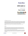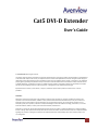
1
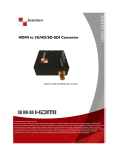
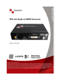
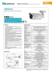
Cat5 DVI-D Extender User’s Guide © 2007 Avenview™ Inc. All rights reserved. The contents of this document are provided in connection with Avenview Inc. (“Avenview”) products. Avenview makes no representations or warranties with respect to the accuracy or completeness of the contents of this publication and reserves the right to make changes to specifications and product descriptions at any time without notice. No license, whether express, implied, or otherwise, to any intellectual property rights is granted by this publication. Except as set forth in Avenview Standard Terms and Conditions of Sale, Avenview assumes no liability whatsoever, and disclaims any express or implied warranty, relating to its products including, but not limited to, the implied warranty of merchantability, fitness for a particular purpose, or infringement of any intellectual property right. Reproduction of this manual, or parts thereof, in any form, without the express written permission of Avenview Inc. is strictly prohibited. Disclaimer While every precaution has been taken in the preparation of this document, Avenview Inc. assumes no liability with respect to the operation or use of Avenview hardware, software or other products and documentation described herein, for any act or omission of Avenview concerning such products or this documentation, for any interruption of service, loss or interruption of business, loss of anticipatory profits, or for punitive, incidental or consequential damages in connection with the furnishing, performance, or use of the Avenview hardware, software, or other products and documentation provided herein. Avenview Inc. reserves the right to make changes without further notice to a product or system described herein to improve reliability, function or design. With respect to Avenview products which this document relates, Avenview disclaims all express or implied warranties regarding such products, including but not limited to, the implied warranties of merchantability, fitness for a particular purpose, and non-infringement. www.avenview.com 1 Table of Contents Getting Started ....................................................................................................................................... 3 Key Features ........................................................................................................................................... 3 System Devices and Functions ........................................................................................................... 4 DVI-C5-S Transmitter...................................................................................................................... 4 DVI-C5-R Transceiver ...................................................................................................................... 4 Panel Description ................................................................................................................................... 5 DVI-C5-S Transmitter and DVI-C5-R Transceiver................................................................................ 5 Cable and Accessories ............................................................................................................................ 6 Installation and Operation ..................................................................................................................... 6 DVI-C5-S Transmitter Installation....................................................................................................... 6 DVI-C5-R Installation .......................................................................................................................... 7 Selection of Cable............................................................................................................................... 8 Installation of Multiple Transceivers and Display ........................................................................ 11 Specifications ....................................................................................................................................... 12 DVI Transmitter and Transceiver ..................................................................................................... 12 www.avenview.com 2 Getting Started The Cat5 DVI-D Extender system consists of a Transmitter and one or more Transceivers. The system can extend DVI-D signals over Cat5/5e/6 cable. By cascading Transceivers it is possible to extend the DVI-D signal to any length. By taking advantage of low-cost Cat5/5e/6 FTP cable, the Cat5 DVI-D Extender can simplify installation and save cost. With its unlimited cascading capacity you can extend your digital video displays almost anywhere. To simplify installation the Transmitter and Transceiver units are fitted with a magnetic pad enabling them to be quickly attached to metal surfaces. A screw fixing plate is also included for permanent installations. The Cat5 DVI-D Extender system is perfect for digital signage and public information display applications where crystal-clear, high-resolution digital video needs to be shown without distance limitations. Key Features Unlimited cascading of DVI-D over Cat 5 / 5e / 6 cable. The system consists of a Transmitter and one or more Transceivers Transmitter can broadcast DVI-D locally and extend one DVI-D signal over RJ45 interface Transceiver has one DVI-D output port and cascading function to extend the DVI-D signal over Cat 5 / 5e / 6 cable Video Amplifier Bandwidth: 1.65GHz Maximum distance and resolution between Transmitter and Transceiver is: a. 80m (275 ft) at 800x600 b. 50m (175 ft) at 1024x78 c. 40m (150 ft) at 1280x1024 DVI Input / Output Connector: DVI-D Built-in EQ control to adjust the video quality LED status to indicate the DVI signal activity Magnetic pad and metal plate for easy installation www.avenview.com 3 System Devices and Functions Transmitter DVI-C5-S a. Built-in EQ control to adjust the video quality b. Built-in one RJ45 DVI Output c. Built-in one RJ45 port for system output which can be connected by Cat 5 / 5e / 6 cable and send signal to System Receiver Transceiver DVI-C5-R d. Built-in EQ control to adjust the video quality e. Built-in one RJ45 DVI Output f. Built-in one RJ45 port for system output which can be connected by Cat 5 / 5e / 6 cable and send signal to System Receiver www.avenview.com 4 Panel Description DVI-C5-S Transmitter and DVI-C5-R Transceiver www.avenview.com 5 Cable and Accessories DVI-HDMI Cable for Player Installation and Operation DVI-C5-S Transmitter Installation a. First Time Setup: Turn off the DVI output device (PC or DVD Player) and monitors. b. Device Connection: Connect local DVI monitor (M1) to the “DVI/MI OUT” of the Transmitter. Use the DVI-HDMI cable, plug the HDMI end to “INPUT” port of the Transmitter and the DVI-D end to PC or DVD Player’s DVD-D video port. Connect the power adapter to the “5VDC” and plug into the power outlet c. System Turn ON: Turn on your DVI output device and monitor to confirm the functionality of the display. The “M1 LINK” LED of the Transmitter should display orange to confirm the connection of a local DVI monitor. d. Remote Monitors: Make sure the remote monitor(s) to be connected to the DVI-C5-R Transceiver can display the broadcast video resolution. www.avenview.com 6 e. EQ Adjustment: You can adjust the EQ control to Auto mode by rotating the EQ control Anticlockwise. The “EQ” and “AUTO” LEDSs will display blue. After connecting the extender system, if you see dynamic dots on unclear image on the DVI, you need to adjust the signal from Transmitter. f. EDID Simulation: The Transmitter has built-in EDID simulator. When local DVI monitor is connected to Transmitter, it will automatically record the EDID data from DVI Monitor. When a local DVI monitor is not connected the Transmitter will simulate the EDID data and activate the DVI signal on the PC or DVD Player. DVI-C5-R Installation a. First Time Connection: Connect DVI Monitor’s DVI Cable to the receiver and TURN ON the monitor. b. Device Connection: Plug power adapter to DVI-C5-R (Transceiver), the “PWR” LED and “M1 LINK” will turn ON. The other “LINK” LED should turn off because there is no input of video signal from “LINK IN” port. c. EQ Adjustment: You can adjust the EQ control to Auto Mode by rotating the EQ Anticlockwise. The “EQ” and “AUTO” LEDs will turn ON Blue. If noise or unstable image is seen on the local DVI monitor, it indicates the DVI signal received by the Transmitter needs to be adjusted. You can also adjust the EQ control for better image display. This changes the EQ into manual mode. The “EQ” and “AUTO” LED will turn off to indicate the manual EQ Mode. www.avenview.com 7 Selection of Cable a. Selection: Most makes and versions of Cat 5/5e/6 cables will work with DVI-C5-S Transmitter and DVI-C5-R Transceivers. However, since the quality and characteristics of Cat 5/5e/6 cables varies it has been found that some perform better than others. The major factor influencing the transmitting distance is the skew property of the cables. Skew represents the difference in propagation delay between the fastest and slowest set of wire pairs. A lower skew will mean a longer video transmitting distance. Cat 5/5e/6 cable with a skew of lower than 15ns/100m should enable a cascading length of: < 80m (275ft) @ 800 x 600 < 50m (175ft) @ 1024 x 768 < 40m (150ft) @ 1280 x 1024 b. Skew Property: A Cat 5/5e/6 cable with a skew lower than 15ns/100m should enable a cascading length of < 80m (275 ft) at 800x600, <50m at 1024x768, and < 40m at 1280x1024. www.avenview.com 8 c. Termination: The RJ45 terminations to the Cat 5/5e/6 cable must be made to the EIA 568B specifications. 1. 5. Orange White Blue White 2. Orange 3. Green White 6. Green 7. Brown White The EIA/TIA definition of 568B in the pin assignment 4. 8. Blue Brown PAIR 3 PAIR 2 PAIR 1 PAIR 4 JACK POSITION www.avenview.com 9 d. Connect the Cable: Plug one ends of UTP cable to DVI-C5-S Transmitter’s “LINK IN/OUT” port and the other end to the DVI-C5-R Transceiver’s “LINK IN/OUT” port. The monitor connected to the Transceiver should now display and the “LINK” LED should turn green to indicate the DVI signal activation. Use EQ control to adjust the video quality for best signal. Installation Diagram of DVI-C5-S and DVI-C5-R e. Extending Audio Signals: The DVI-C5-S Transmitter and DVI-C5-R Transceiver are not able to extend audio signals. Use a pair of Avenview AUD-RJ11 Audio Extenders with 4-wire phone cable and RJ11 connectors to extend the audio signal. General Troubleshooting Problem Possible Solution Off-Center Screen Image, Odd Colors or No Picture No Image www.avenview.com Try adjusting the brightness, sharpness, contrast, and color balance controls of your monitor. Try adjusting the centering and positioning controls of your monitor to position the picture on the screen. Ensure that the monitor cable is securely fastened to the DVI and Monitor port. 10 Installation of Multiple Transceivers and Display a. Multiple Transceivers: By using additional DVI-C5-R Transceivers, it is possible to extend the system almost indefinitely to remote DVI-D displays. Installation Diagram of Multiple Transceivers Ensure that common grounding is maintained to minimize ground loops and interference for larger group of cascaded Transceivers. www.avenview.com 11 Specifications DVI Transmitter and Transceiver Model Description Input Output Max Distance and Resolution Video Control Signal Type Power Consumption Dimension (LxWxH) mm www.avenview.com DVI-C5-S DVI-C5-R 1 Port DVI-D Transmitter 1 Port DVI-D Transceiver HDMI (DVI – HDMI Connector) RJ45 x 1 DVI Female x 1, RJ45 x 1 DVI Female x 1, RJ45 x 1 With each cascading length: < 80m (275ft) @ 800 x 600 < 50m (175ft) @ 1024 x 768 < 40m (150ft) @ 1280 x 1024 EQ x 1 DVI-D DC 5V, 650mA 68 x 42 x19 12 www.avenview.com 13