1
Nortel Networks Media Processing
Server Series COMMGR Reference
Manual
(Software Release 1.0 )
Publication#: P0988083
Document Release: 1.0
Release Date: April 1, 2002
Nortel Networks Media Processing Server Series COMMGR Reference Manual
Important Notice
Nortel Networks reserves the right to make changes in the contents of this publication
including functions and specifications identified herein without notice.
The material contained in this document is intended for Nortel Networks personnel
and licensed customers with a non-disclosure agreement or standard contract.
In the absence of a written agreement to the contrary, Nortel Networks assumes no
liability for applications assistance, customer’s product/application/concepts, or
infringements of patents or copyrights of third parties arising from the use of systems
and architectures described herein. Nor does Nortel Networks warrant or represent
that any license, either expressed or implied, is granted under any patent right,
copyright, or other combination of technology, architecture, or software as might be or
is already in use.
This document should not be reproduced, disseminated, or otherwise disclosed
without prior written consent from an officer of Nortel Networks.
This document has been copyrighted by Nortel Networks and may not be duplicated.
Copyright © 2002 Nortel Networks, All Rights Reserved
Page ii
Nortel Networks Confidential
#P0988083 Ver. 1.0
COMMGR Reference Manual
Table of Contents
Table of Contents
Preface . . . . . . . . . . . . . . . . . . . . . . . . . . . . . . . . . . . . . . . . . . . . . . . . . . . . . . . . . . . vi
Scope . . . . . . . . . . . . . . . . . . . . . . . . . . . . . . . . . . . . . . . . . . . . . . . . . . . . . . . . . . vi
Intended Audience . . . . . . . . . . . . . . . . . . . . . . . . . . . . . . . . . . . . . . . . . . . . . . . vi
How to Use This Manual . . . . . . . . . . . . . . . . . . . . . . . . . . . . . . . . . . . . . . . . . vii
Organization of This Manual . . . . . . . . . . . . . . . . . . . . . . . . . . . . . . . . . . . . . viii
Conventions Used in This Manual . . . . . . . . . . . . . . . . . . . . . . . . . . . . . . . . . . . ix
Solaris and Windows NT Conventions . . . . . . . . . . . . . . . . . . . . . . . . . . . . . . . . x
Trademark Conventions . . . . . . . . . . . . . . . . . . . . . . . . . . . . . . . . . . . . . . . . . . . x
Manual (Man) Pages . . . . . . . . . . . . . . . . . . . . . . . . . . . . . . . . . . . . . . . . . . . . . . xi
1. Introduction . . . . . . . . . . . . . . . . . . . . . . . . . . . . . . . . . . . . . . . . . . . . . . . . . . . .2
Overview of Host Computer Communications . . . . . . . . . . . . . . . . . . . . . . . . .
MPS Software Architecture . . . . . . . . . . . . . . . . . . . . . . . . . . . . . . . . . . . . . . . .
Protocol Architecture . . . . . . . . . . . . . . . . . . . . . . . . . . . . . . . . . . . . . . . . . . . . .
Telephone Switching Environments . . . . . . . . . . . . . . . . . . . . . . . . . . . . . . . . . .
Supported Protocols . . . . . . . . . . . . . . . . . . . . . . . . . . . . . . . . . . . . . . . . . . . . . .
2
4
6
8
9
2. Configuration Files. . . . . . . . . . . . . . . . . . . . . . . . . . . . . . . . . . . . . . . . . . . .12
The commgr.cfg File . . . . . . . . . . . . . . . . . . . . . . . . . . . . . . . . . . . . . . . . . .
The vos.cfg File . . . . . . . . . . . . . . . . . . . . . . . . . . . . . . . . . . . . . . . . . . . . . .
The <protocol>.cfg File . . . . . . . . . . . . . . . . . . . . . . . . . . . . . . . . . . . . .
The host#.rc File . . . . . . . . . . . . . . . . . . . . . . . . . . . . . . . . . . . . . . . . . . . . .
The vpshosts File . . . . . . . . . . . . . . . . . . . . . . . . . . . . . . . . . . . . . . . . . . . . .
13
14
15
16
17
3. Configuration and Status Commands . . . . . . . . . . . . . . . . . . . . . . . . .20
Command Syntax and Usage . . . . . . . . . . . . . . . . . . . . . . . . . . . . . . . . . . . . . .
Global Commands . . . . . . . . . . . . . . . . . . . . . . . . . . . . . . . . . . . . . . . . . . .
Virtual Terminal Range Commands . . . . . . . . . . . . . . . . . . . . . . . . . . . . .
Protocol Daemon Commands . . . . . . . . . . . . . . . . . . . . . . . . . . . . . . . . . . .
Protocol Configuration . . . . . . . . . . . . . . . . . . . . . . . . . . . . . . . . . . . . . . . . . . .
Manager-Type Protocol Configuration . . . . . . . . . . . . . . . . . . . . . . . . . . .
Client/Server-Type Protocol Configuration . . . . . . . . . . . . . . . . . . . . . . . .
Host Session Assignment . . . . . . . . . . . . . . . . . . . . . . . . . . . . . . . . . . . . . . . . .
Virtual Terminal Mapping . . . . . . . . . . . . . . . . . . . . . . . . . . . . . . . . . . . . . . . .
Host Mode Configuration . . . . . . . . . . . . . . . . . . . . . . . . . . . . . . . . . . . . . . . . .
24-Byte Header and Pace Mode Parameters . . . . . . . . . . . . . . . . . . . . . . .
Transaction Codes and Status-Only Messages . . . . . . . . . . . . . . . . . .
Header Message Translation . . . . . . . . . . . . . . . . . . . . . . . . . . . . . . . .
Interacting with Multiple Hosts . . . . . . . . . . . . . . . . . . . . . . . . . . . . . .
Host Login Headers . . . . . . . . . . . . . . . . . . . . . . . . . . . . . . . . . . . . . . .
24-Byte Header-Specific Parameters . . . . . . . . . . . . . . . . . . . . . . . . . . . . .
Host Numeric Vocabulary Element Format . . . . . . . . . . . . . . . . . . . .
Call Referral Parameters . . . . . . . . . . . . . . . . . . . . . . . . . . . . . . . . . . .
Host Control of Voice Prompts . . . . . . . . . . . . . . . . . . . . . . . . . . . . . .
Status Message Timestamp . . . . . . . . . . . . . . . . . . . . . . . . . . . . . . . . .
#P0988083 Ver. 1.0
Nortel Networks Confidential
20
21
21
22
22
23
24
25
26
27
28
29
30
30
31
31
31
32
33
33
Page iii
Nortel Networks Media Processing Server Series COMMGR Reference Manual
Rawtty mode . . . . . . . . . . . . . . . . . . . . . . . . . . . . . . . . . . . . . . . . . . . . . . . .
Screen Mode . . . . . . . . . . . . . . . . . . . . . . . . . . . . . . . . . . . . . . . . . . . . . . . .
Host Response Timers . . . . . . . . . . . . . . . . . . . . . . . . . . . . . . . . . . . . . . . . . . . .
Keyboard Status . . . . . . . . . . . . . . . . . . . . . . . . . . . . . . . . . . . . . . . . . . . . . . . .
AID Keys . . . . . . . . . . . . . . . . . . . . . . . . . . . . . . . . . . . . . . . . . . . . . . . . . . . . . .
Host Availability . . . . . . . . . . . . . . . . . . . . . . . . . . . . . . . . . . . . . . . . . . . . . . . .
Host Status Commands . . . . . . . . . . . . . . . . . . . . . . . . . . . . . . . . . . . . . . . . . . .
34
34
35
36
37
38
39
4. Virtual Terminal (VT) Configuration . . . . . . . . . . . . . . . . . . . . . . . . . . 42
Virtual Terminal Overview . . . . . . . . . . . . . . . . . . . . . . . . . . . . . . . . . . . . . . . .
Virtual Terminal Assignments . . . . . . . . . . . . . . . . . . . . . . . . . . . . . . . . . . . . .
Virtual Terminal Pooling . . . . . . . . . . . . . . . . . . . . . . . . . . . . . . . . . . . . . . . . . .
VT Allocation to Applications . . . . . . . . . . . . . . . . . . . . . . . . . . . . . . . . . .
VT Pooling Configuration . . . . . . . . . . . . . . . . . . . . . . . . . . . . . . . . . . . . .
VT Pooling Commands . . . . . . . . . . . . . . . . . . . . . . . . . . . . . . . . . . . . . . .
VT Pooling Assignment . . . . . . . . . . . . . . . . . . . . . . . . . . . . . . . . . . . . . . .
VT Pooling Timeout Value . . . . . . . . . . . . . . . . . . . . . . . . . . . . . . . . . . . . .
VT Pooling Access Method . . . . . . . . . . . . . . . . . . . . . . . . . . . . . . . . . . . .
Selecting the Current Pool . . . . . . . . . . . . . . . . . . . . . . . . . . . . . . . . . . . . .
Example Configuration . . . . . . . . . . . . . . . . . . . . . . . . . . . . . . . . . . . . . . . .
Removing VTs from a Pool . . . . . . . . . . . . . . . . . . . . . . . . . . . . . . . . . . . .
Virtual Terminal Status Information . . . . . . . . . . . . . . . . . . . . . . . . . . . . . . . . .
Host/VT Status Information . . . . . . . . . . . . . . . . . . . . . . . . . . . . . . . . . . . .
Determining the Status of a Defined VT Pool . . . . . . . . . . . . . . . . . . . . . .
Displaying VT Pooling Statistics . . . . . . . . . . . . . . . . . . . . . . . . . . . . . . . .
Resetting VT Pooling Statistics . . . . . . . . . . . . . . . . . . . . . . . . . . . . . . . . .
42
43
44
45
46
47
48
49
49
51
52
53
55
55
57
59
60
A. Host Character Sets . . . . . . . . . . . . . . . . . . . . . . . . . . . . . . . . . . . . . . . . . . 62
Overview . . . . . . . . . . . . . . . . . . . . . . . . . . . . . . . . . . . . . . . . . . . . . . . . . . . . . .
Commands . . . . . . . . . . . . . . . . . . . . . . . . . . . . . . . . . . . . . . . . . . . . . . . . . . . . .
File Format . . . . . . . . . . . . . . . . . . . . . . . . . . . . . . . . . . . . . . . . . . . . . . . . . . . .
Sample Files . . . . . . . . . . . . . . . . . . . . . . . . . . . . . . . . . . . . . . . . . . . . . . . . . . .
62
62
63
64
Index . . . . . . . . . . . . . . . . . . . . . . . . . . . . . . . . . . . . . . . . . . . . . . . . . . . . . . . . . . . . 68
Page iv
Nortel Networks Confidential
#P0988083 Ver. 1.0
P
Preface
This chapter covers:
1. Scope of this manual
2. Intended audience
3. Use and organization of this
manual
4. Documentation and trademark
Conventions
5. Manual (Man) pages
Nortel Networks Media Processing Server Series COMMGR Reference Manual
Preface
Scope
The Nortel Networks Media Processing Server Series COMMGR Reference Manual
details how to configure a Nortel Networks Media Processing Server Series (MPS)
system to communicate with various types of host computer systems. This manual
provides background information and details about configuration parameters common
to most host environments, as well as information about optional MPS features that
can be used at specific sites.
This manual covers topics that are specific to the configuration and operations of MPS
systems. It is not intended to explain general telephony concepts or the characteristics
of specific types of host computers.
Although some application programming depends on the type of host environment in
use, this manual does not cover application programming techniques. See the
PeriProducer Reference Manual for details on application programming.
Intended Audience
This manual is intended for the staff members who configure and program the MPS
for use with specific host computers.
The reader should be familiar with telecommunications and computer equipment,
their functions and associated terminology. In addition, the reader must be familiar
with the characteristics of the specific installation, including on-site power systems,
computers, peripherals, and telephony components.
This manual assumes that the user has completed an on-site system familiarization
training program conducted as part of the initial system installation. Basic knowledge
of the Solaris and/or Windows NT operating system(s) is also assumed.
Page vi
Nortel Networks Confidential
#P0988083 Ver. 1.0
COMMGR Reference Manual
Preface
How to Use This Manual
This manual uses many standard terms relating to computer system and software
application functions. However, it contains some terminology that can only be
explained in the context of the MPS system. Refer to the Glossary of MPS
Terminology for definitions of these terms.
Initially, this manual should be read at least once from start to finish. Later, the Table
of Contents and Index can be used to locate topics of interest for reference and
review.
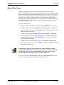
If this document is being viewed online, use the hypertext links to quickly locate
related topics. Click once with the mouse while the cursor is positioned over the
hypertext link. Click on any point in a Table of Contents entry to move to that topic.
Click on the page number of any Index entry to access that topic page. Use the
hyperlinks at the top and bottom of each online “page” as needed when navigating the
documentation. Pass the cursor over the Nortel Globemark to display the title,
software release, publication and revision number, and release date for the manual.
For additional related information, use the Reference Material link in PeriDoc. To
become familiar with various specialized textual references within the manual, see
Conventions Used in This Manual on page ix.
Periphonics is now part of Nortel Networks. The name Periphonics, and
variations thereof, only appear in this manual where it is refers specifically to
certain product names and commands. (As examples, a PeriProducer
application, the PERImps package, the perirev command, etc.)
#P0988083 Ver. 1.0
Nortel Networks Confidential
Page vii
Nortel Networks Media Processing Server Series COMMGR Reference Manual
Organization of This Manual
The following briefly outlines the structure of this manual:
Chapter 1. Introduction
Provides an overview of host communications configuration and software architecture.
Chapter 2. Configuration Files
Describes the configuration of the files relevant to host communications. Sample configuration files are provided.
Chapter 3. Configuration and Status Commands
Describes the aspects of communications configuration common to most installations.
The topics include: command syntax, VSH command execution, loading the
communications software, specifying the desired protocol, determining host link
availability, setting common parameters, and selecting a particular host session.
Chapter 4. Virtual Terminal (VT) Configuration
Describes the configuration and use of Virtual Terminals (VTs). Topics include
general configuration issues, assigning VTs to phone lines, VT Pooling, VT status
information, and application programming notes.
Appendix A. Host Character Sets
Describes the character set conversion tables for use with specific types of host
computers and applications. This is supported only for the LU6.2 and VPSTN3270
protocols.
Page viii
Nortel Networks Confidential
#P0988083 Ver. 1.0
COMMGR Reference Manual
Preface
Conventions Used in This Manual
This manual uses different fonts and symbols to differentiate between document
elements and types of information. These conventions are summarized in the
following table.
Conventions Used in This Manual
Notation
Description
Normal text
Normal text font is used for most of the document.
important term
The Italics font is used to introduce new terms, to highlight meaningful words or phrases, or to
distinguish specific terms from nearby text.
system
command
This font indicates a system command and/or its arguments. Such keywords are to be entered
exactly as shown (i.e., users are not to fill in their own values).
file name /
directory
This font is used for highlighting the names of disk directories, files, and extensions for file
names. It is also used to show displays on text-based screens (e.g., to show the contents of a
file.)
on-screen field
This font is used for field labels, on-screen menu buttons, and action buttons.
<KEY NAME>
A term that appears within angled brackets denotes a terminal keyboard key, a telephone
keypad button, or a system mouse button.
Book Reference
This font indicates the names of other publications referenced within the document.
cross reference
A cross reference or man page reference is shown on the screen in blue. Click on the cross
reference to access the referenced location. A cross reference that refers to a section name
accesses the first page of that section. Click on the man page reference to elicit a pop-up
window displaying the subject man page.
The Note icon identifies notes, important facts, and other keys to understanding.
!
The Caution icon identifies procedures or events that require special attention. The icon
indicates a warning that serious problems can arise if the stated instructions are improperly
followed.
The flying Window icon identifies procedures or events that apply to the Windows NT
operating system only. (1)
The Solaris icon identifies procedures or events that apply to the Solaris operating system
only. (2)
(1): Windows NT and the flying Window logo are either trademarks or registered trademarks of the Microsoft
Corporation.
(2): Solaris is a trademark or registered trademark of Sun Microsystems, Inc. in the United States and other
countries.
#P0988083 Ver. 1.0
Nortel Networks Confidential
Page ix
Nortel Networks Media Processing Server Series COMMGR Reference Manual
Solaris and Windows NT Conventions
This manual depicts examples (command line syntax, configuration files, and screen
shots) in Solaris format. In certain instances, Windows NT specific commands,
procedures, or screen shots are shown where required. The following table lists
examples of general operating system conventions to keep in mind when using this
manual with either the Solaris or NT operating system.
Solaris
Windows NT
Environment
$VPSHOME
%VPSHOME%
Paths
$VPSHOME/common/etc
%VPSHOME%\common\etc
Command
<command> &
start /b <command>
Trademark Conventions
The following trademark information is presented here and applies throughout this
publication for discussions of third-party products. Trademark information is not
repeated hereafter.
Solaris is a trademark or registered trademark of Sun Microsystems, Inc. in the United
States and other countries.
Microsoft, Windows, Windows NT, Internet Explorer, the Flying Windows logo, and
Microsoft Host Integration Server 2000 are either trademarks or registered trademarks
of Microsoft Corporation.
Netscape® and the Netscape N® and Ship's Wheel® logos are registered trademarks
of Netscape Communications Corporation in the U.S. and other countries. Netscape
Navigator is also a trademark of Netscape Communications Corporation and may be
registered outside the U.S.
GeoTel® and ICM (Intelligent Contact Management)® are registered trademarks of
Cisco Systems.
Brixton® SNA Server is a trademark of Brixton Systems.
IEX® and TotalNet® are registered trademarks of the Tekelec Company.
Page x
Nortel Networks Confidential
#P0988083 Ver. 1.0
COMMGR Reference Manual
Preface
Manual (Man) Pages
Manual (man) pages provide access to documentation about Solaris system
commands, MPS commands, status/exception conditions, and alarm information. Man
pages can be displayed from any command line on Solaris systems. On NT systems,
man pages can be displayed from a DOS prompt/VSH prompt. Man pages appear in a
separate browser window. The particular browser used depends on the software
installed on the system and which browser is set as the default. In addition, man pages
are always accessible through PeriDoc’s Search page and through hypertext links
within the documents.
To access a Man Page for:
•
a Solaris system command, use the syntax man <command> (Solaris only).
•
an MPS command, use the syntax mpsman <processname> <command>.
On Solaris systems only, enter man mpsman for a detailed description of using
MPS command manual pages.
•
an MPS alarm, use the syntax mpsalarm <processname> <alarm#>.
On Solaris systems only, enter man mpsalarm for a detailed description of
using alarm manual pages, or man alarmintro for an overview of MPS
alarms and the alarm database.
•
an MPS status/exception condition, use the syntax conman <condition>.
On Solaris systems only, enter man conman for a detailed description of using
MPS condition manual pages.
The man page scripts rely on the Windows NT registry settings for default
browser information. Older browsers do not set the registry entries required by
the man page scripts. Do not use command line man pages if you are using
browsers older than Netscape Navigator 4/Internet Explorer 4.
If you are viewing this document online, click any command highlighted in blue to
open a window displaying the manual page for that command.
#P0988083 Ver. 1.0
Nortel Networks Confidential
Page xi
Nortel Networks Media Processing Server Series COMMGR Reference Manual
This page has been intentionally left blank.
Page xii
Nortel Networks Confidential
#P0988083 Ver. 1.0
1
Introduction
This chapter covers:
1. Communications configuration overview
2. Software architecture
Nortel Networks Media Processing Server Series COMMGR Reference Manual
1. Introduction
The Nortel Networks Media Processing Server Series (MPS) is an IVR (Interactive
Voice Response) system with augmentations for multimedia functions and advanced
telephone switching. An MPS can function as a stand-alone services system, with its
own transaction processing and storage facilities, or be integrated into serviceprovider environments with their own central computer systems.
Overview of Host Computer Communications
In a telephony services environment, the MPS is the link between network features
and the calling community. External systems in the network connected to the MPS are
referred to as host computers. Generally, hosts are of the mini, mainframe, or
workstation classification. They provide database and transaction processing
functions, which are integrated with the voice and media features of the MPS. The
MPS can facilitate any data, voice, or telephony service that the network’s host
computers are designed to provide.
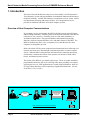
Before the advent of IVR systems, computer-based transactions involved having a live
operator enter and receive data through a terminal connected to a central computer
system. When the MPS is integrated into this kind of basic transaction processing
environment, it emulates the actions of the operator as it interacts with the caller,
host(s), and internal system resources.
The actions of the MPS are governed by applications. These are scripts containing
programmed instructions, such as for receiving caller input, providing voice output,
accessing the host, etc. MPS applications are created using PeriProducer, which is a
GUI-type editor that allows visual sequencing of application instructions. (See the
PeriProducer User’s Guide.)
Host
8
Telephone
network
Protocol-based
interaction
Terminal
Caller
Computer network
Operator
Basic Transaction Processing Environment
Page 2
Nortel Networks Confidential
Database
#P0988083 Ver. 1.0
COMMGR Reference Manual
Introduction
An application is activated by associating it with one of the MPS telephone lines. The
set of lines in the system can run multiple copies of the same application, different
applications, or any combination. When an application’s phone number is dialed, the
application activates and interacts with the caller based on it’s programmed
instructions.
If an application requires access to a host, the MPS assigns a set of internal hardware
and software resources, referred to as a Virtual Terminal (VT), to the application’s
phone line. This VT is seen by the host as an operator’s terminal. When issuing
configuration commands to a VT, the VT is identified to the system by a unique
service ID.
Read and write operations are performed between the VT and the host in the same
manner as is done with a standard terminal, based on the characteristics of a particular
host communications protocol. A protocol is a standardized format for transmitting
data between computer systems. The format consists of command codes, data values,
delimiters, etc. that both computers can recognize. To send data to and receive data
from a host, the MPS must be configured for the appropriate protocol.
An application can communicate with up to eight hosts, each of which can use a
different protocol. Applications can easily change the host session as needed, which
means to switch from one host to the next. The particular protocol expected by each
host is set up in the MPS configuration files.
Host
Telephone
network
Virtual
Application
Terminal
Protocol-based
interaction
Computer network
MPS
8
Database
Caller
Basic MPS Transaction Processing Network
#P0988083 Ver. 1.0
Nortel Networks Confidential
Page 3
Nortel Networks Media Processing Server Series COMMGR Reference Manual
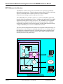
MPS Software Architecture
The MPS host communications subsystem contains a set of processes specifically
dedicated to host interaction. The host subsystem resides in the VOS (Voice Operating
Software) of the MPS, and is comprised of two layers: the COMMGR
(Communications Manager) process and the protocol layer.
The COMMGR process provides a generic (i.e., protocol-independent) application
interface for host communications services. It mediates the interaction between MPS
applications and the protocol-layer process(es). The COMMGR is also responsible
for the majority of data processing related to external communications, including
configuration, application-to-host session mapping, and host input/output processing.
A single COMMGR process runs on each MPS in the network.
The exact software arrangement of the protocol layer depends on the protocol type. In
this layer, there is one main process (generally a protocol server or manager process)
that handles the communications needs of all MPS applications using that protocol.
Depending on the design of a particular protocol, there might be multiple ancillary
interface processes in the protocol layer.
MPS
Solaris/NT
ASE
VMS
VENGINE(s)
Application(s)
MXVMT
VSH
System Console
VOS
CCM
COMMGR
Telephone
Network
Protocol
daemon
Host communications subsystem
Host
MPS Communications Software Architecture
Page 4
Nortel Networks Confidential
#P0988083 Ver. 1.0
COMMGR Reference Manual
Introduction
The system processes relevant to host communications are described below.
MPS System Software
VSH
V-shell is the command interface for MPS configuration and operations. Configuration and status
commands can be issued via the VSH tool or from the system’s configuration files. VSH receives
status information from the various system processes and displays messages on the console as
appropriate.
ASE
The Application Service Environment software is dedicated to providing the data and services
requested by applications. The ASE exists on a separate workstation, referred to as the applications
processor. The workstation can be either an open-systems Solaris or Windows NT implementation.
applications Interactive Voice Response or multimedia script created with PeriProducer. An
application runs on a system phone line. Multiple instances of the same application
can be assigned to different lines. Each application is associated with it’s own VT.
VOS
VENGINE
Software process that executes an application. A single VENGINE process is required
for each application telephone line.
VMS
The VENGINE Message Server provides a message funnel between the ASE and VOS
processes. On a node that contains multiple MPS systems, VMS provides connectivity
between the application processor and each MPS. One VMS is required for each
MPS.
MXVMT
The Media Transaction VENGINE Message Translator relays messages between the
ASE and VOS processes. One MXVMT process is required for each MPS.
The Voice Operating Software is the set of processes that provide the low-level system functions in
the MPS. These functions include telephony and host I/O, and are common to most types of
applications.
COMMGR
The Communications Manager provides a generic application interface for host
communications services. A single COMMGR is required for each MPS in the
network.
protocol
daemon
Software process that implements the particular communications protocol. The
protocol layer links the COMMGR with the host computer. With some protocols (e.g.,
CCA, ATTE, etc.), the protocol daemon invokes driver programs to manage individual
VT sessions.
CCM
The Call Control Manager configures and controls low-level telephony interaction.
#P0988083 Ver. 1.0
Nortel Networks Confidential
Page 5
Nortel Networks Media Processing Server Series COMMGR Reference Manual
Protocol Architecture
All protocols require use of the COMMGR and a server or manager process specific to
each protocol. This process is called the protocol daemon. Each protocol also has
unique internal architecture and might require special hardware interfaces for the host.
For some protocols, such as certain variations of Credit Card Authorization, the
protocol layer is implemented as a server, which can be shared by the COMMGR
client processes on multiple MPS systems.
MPS
MPS
Solaris/NT
Solaris/NT
ASE
ASE
VOS
VOS
COMMGR
COMMGR
Protocol
server
daemon
Host
MPS Multiple-COMMGR Architecture
For protocols like GeoTel or IEX, the protocol layer consists of a single server process
without any interface processes. For some other protocols, the server software
spawns multiple interface processes, one for each application VT.
MPS
Solaris/NT
ASE
VOS
COMMGR
Protocol
server
daemon
Protocol interfaces
Host
MPS Protocol Architecture with Support Processes
Page 6
Nortel Networks Confidential
#P0988083 Ver. 1.0
COMMGR Reference Manual
Introduction
Depending on the protocol, the MPS interacts with the host either by modem or via
LAN/WAN-type connections (TCP/IP, Ethernet, SDLC, Token Ring, X.25 or Async).
Some environments incorporate the Brixton PU2.1 server with VPSTN3270
functionality to additionally mediate host communications.
MPS
Solaris/NT
ASE
VOS
COMMGR
MODEM
Protocol
server
daemon
MODEM
MODEM
Host
MPS
Solaris/NT
ASE
VOS
COMMGR
Protocol
daemon
VT100 or
VPSTN3270
Host
MPS
Solaris/NT
ASE
VOS
COMMGR
Protocol
daemon
Brixton
PU2.1
server
Token ring, Ethernet,
or SDLC
Host
MPS Protocol Architecture with Various Host Connections
#P0988083 Ver. 1.0
Nortel Networks Confidential
Page 7
Nortel Networks Media Processing Server Series COMMGR Reference Manual
Telephone Switching Environments
In large-scale, enterprise-type networks, the MPS can be integrated with an intelligent
router system that performs call load balancing and network reporting.
This type of installation requires use of either the GeoTel or Nortel Networks’ IEX
systems. Although GeoTel and IEX use the host communications facilities of the
MPS, they are not considered host protocols in the traditional sense. Rather, they are
enterprise-type communications protocols that allow interaction between an MPS and
telephony-network-based services.
A typical call routing scenario is described below:
1.
2.
3.
4.
5.
A caller dials phone number for a particular network service.
The telephone network requests switching instructions from the intelligent router.
The intelligent router sends switching instructions to telephone network.
The call is routed to an available MPS system.
If the application can complete the call, the MPS sends updated call status and line
availability information to the intelligent router. If the caller requires additional
assistance, the MPS sends a call routing request to the intelligent router.
6. The ICM transmits the new call destination to the MPS.
7. The MPS transmits call switching instructions to the network.
8. The call is connected with a customer service agent.
8
Caller
8 1
8
4
Telephone
network
4
MPS
MPS
MPS
7
Agent
2
3
5
6
Intelligent Router System
MPS Enterprise Network Environment
Page 8
Nortel Networks Confidential
#P0988083 Ver. 1.0
COMMGR Reference Manual
Introduction
Supported Protocols
For the MPS to communicate with a host, the appropriate protocol software must be
configured on the MPS. The specific architecture, configuration, operation, and
features of each host protocol is documented in it’s own manual.
The following protocols are currently supported by the MPS:
Protocols Supported by the MPS
Host Protocol
Connection Type
MPS Protocol Name
TELNET
TCP/IP
ATTE (VT100 terminal emulation)
Async
serial
ATTE
TELNET 3270
TCP/IP
VPSTN3270 (RFC1576, RFC1646)
PPI
3270 LU type 2
Ethernet (802.2)
Token Ring (802.5)
SDLC
X.25
VPSTN3270 - Solaris (requires Brixton
PU2.1 Server)
VPSTN3270 - Windows NT (requires
Microsoft Host Integration Server 2000)
LU type 6.2
Ethernet (802.2)
Token Ring (802.5)
SDLC
X.25
LU6.2 - Solaris (requires Brixton PU2.1
Server)
LU6.2 - Windows NT (requires Microsoft
Host Integration Server 2000)
Credit Card Authorization
MODEM
CCA_SERV, CCA_MGR
24-Byte Header
PACE
rawtty
visa - credit
TCP/IP (with POS
visanet - batch, credit, debit
port device)
mapp - batch, credit
edc - batch, credit
TCP/IP
etc - credit
POS_SERVER
PaylinX - Vital VirtualNet (requires
PERIjsb, and PaylinX Java API)
GeoTel ICM
TCP/IP
GeoTel
IEX
TCP/IP
IEX
Each of these protocols allows up to 255 concurrent host sessions on each MPS, but
the actual limit depends on available system resources, CPU, memory and swap space,
and application requirements.
#P0988083 Ver. 1.0
Nortel Networks Confidential
Page 9
Nortel Networks Media Processing Server Series COMMGR Reference Manual
This page has been intentionally left blank.
Page 10
Nortel Networks Confidential
#P0988083 Ver. 1.0
2
Configuration Files
This chapter covers:
1. The commgr.cfg File
2. The vpshosts File
3. The vos.cfg File
4. The host#.rc File
Nortel Networks Media Processing Server Series COMMGR Reference Manual
2. Configuration Files
For products that are part of the Nortel Networks Media Processing Server Series
(MPS), certain configuration files have to be installed and modified to support host
communications. These files are supplied in generic form when the system is shipped
from the factory. For most sites, these files require only minor modifications to
configure all necessary functions of a given protocol.
For Solaris systems, the configuration files are stored in the directory
$VPSHOME/vpsN/etc/, where “N” indicates the ID number of the particular MPS
unit.
For Windows NT systems, the configuration files are stored in the directory
%VPSHOME%\vpsN\etc\, where “N” indicates the ID number of the particular
MPS unit.
The following configuration files are used in every MPS installation that supports host
communications:
MPS Communications Configuration Files
commgr.cfg
Contains commands that set parameters specific to the
COMMGR process. (See The commgr.cfg File on page 13.)
vos.cfg
Defines process names and their associated TCP/IP port
numbers. This system uses the protocol’s entry in this file to
assign an appropriate port number. (See The vos.cfg File on
page 14.)
<protocol>.cfg Contains commands for the particular protocol daemon. (See
The <protocol>.cfg File on page 15.)
host#.rc
Internal configuration file for a particular host configured in the
commgr.cfg file. (See The host#.rc File on page 16.)
vpshosts
Specifies the network components associated with a particular
node. (See The vpshosts File on page 17.)
The Nortel Networks Media Processing Server Series System Reference Manual
contains additional information about these files not documented here.
Page 12
Nortel Networks Confidential
#P0988083 Ver. 1.0
COMMGR Reference Manual
Configuration Files
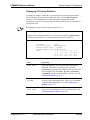
The commgr.cfg File
The main host communications configuration file is called commgr.cfg. The
parameters specified in this file are parsed and interpreted by the COMMGR software
automatically upon system startup.
The configuration requirements of the commgr.cfg file depend on the particular
protocol. Sample commgr.cfg files are provided in each protocol features manual.
In the commgr.cfg file, commands are preceded by the “host #” syntax
construction. The “#” indicates the particular host to which the configuration
parameters will apply. (See Command Syntax and Usage on page 20.)
Up to eight logical hosts can be defined. In the commgr.cfg file, there is one set of
host # commands for each defined host (i.e., a set of commands, as needed for
host 1, host 2, host 3, etc. that configure each of these hosts). An application
issues session commands, as needed, to change the host with which it is
communicating. (See Host Session Assignment on page 25.)
The commands that can be used in this file are documented in Chapter 3.
Configuration and Status Commands. These commands set parameters that
configure the host communications software. Most parameters have default values
suitable for most installations. If a parameter’s default is adequate, the corresponding
command need not be included in the commgr.cfg file. (The commgr.cfg file
usually contains just a few commands for each defined host.)
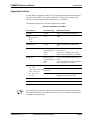
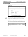
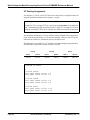
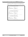
A sample commgr.cfg configuration file for a dual-host, 96-line T1 system is
shown below.
Sample commgr.cfg File
host
host
host
host
host
host
#P0988083 Ver. 1.0
1
1
1
2
2
2
protocol <protocol1_name>
svcid 1-48 sess 1
svcid 1-48 assignvt 1
protocol <protocol2_name>
svcid 49-96 sess 2
svcid 49-96 assignvt 49
Nortel Networks Confidential
Page 13
Nortel Networks Media Processing Server Series COMMGR Reference Manual
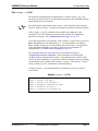
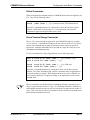
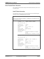
The vos.cfg File
The vos.cfg file defines process names and their associated TCP/IP port numbers.
Each MPS system has its own vos.cfg file.
For nodes that have more than one MPS system, the port numbers are assigned
uniquely in each vos.cfg file for each process. (Port numbers are assigned
automatically when the system software is installed.) In addition, port numbers must
not conflict with Solaris system port numbers. (See the description of the
/etc/services file in the Solaris documentation.) SRP (Startup and Recovery
Process) always uses port number 5999, so no other process can be assigned this port
number.
A dash (“-”) in the PORT column indicates that SRP assigns a unique port to the
process during system startup.
To configure a particular protocol, uncomment the line that references the protocol
name.
Sample vos.cfg File
#
# Example vos.cfg file.
#
# NAME
HOST PORT
trip
tcad
vmm
ccm
vstat
commgr
#
# Uncomment
#
#atte
#vpstn3270
#appc_cm
#cca_mgr
#cca_serv
#plx_mgr
#geotel
#pos_serv
Page 14
-
-
PRI
COMMAND LINE
0
0
0
0
0
0
trip
tcad
vmm
"ccm -c tms -m clean -s 1-180"
vstat
commgr
the appropriate host protocol entries
-
<port>
<port>
0
0
0
0
0
0
0
0
atte
vpstn3270
appc_cm
cca_mgr
cca_serv
plx_mgr
geotel
pos_serv
Nortel Networks Confidential
#P0988083 Ver. 1.0
COMMGR Reference Manual
Configuration Files
The <protocol>.cfg File
Each MPS node has a configuration file specific to the selected protocol, which
contains commands that configure the protocol daemon. The configuration files and
commands for each protocol are documented in their own manuals. Refer to the
manual that covers the particular protocol.
In the case of a server-type protocol, where multiple client MPS systems share a single
protocol server daemon (see Protocol Architecture on page 6), the
<protocol>.cfg exists only on the system that is actually running the process.
Each MPS system has a unique identification number that distinguishes it from other
systems in the network. The <protocol>.cfg file for a given MPS is stored in the
directory $VPSHOME/vpsN/etc, where N indicates the identification number of the
particular system.
The following is important information about issuing protocol daemon commands:
• If there are multiple MPS systems on a single node, the port numbers specified in
each $VPSHOME/vpsN/etc/<protocol>.cfg file must be unique.
• In almost all cases, protocol configuration commands should be specified only in
the <protocol>.cfg file (as opposed to entering them from the command
line). This ensures that after the command sequence is programmed, it will
execute properly and consistently whenever the system is restarted.
• Configuration commands can only be issued when the host link is in a down state.
Since the configuration files are read during system startup, the PG link is always
down at that time.
• Configuration commands can be issued from VSH, but this is generally done only
for the purpose of diagnostics and debugging. Only status commands should be
entered into the VSH tool on production systems.
• Certain commands can include a Virtual Terminal (VT) range to identify
particular lines for which the parameter values are to be set. If the VT range is
omitted, the default VT range is assumed. (See Virtual Terminal Range
Commands on page 21.)
#P0988083 Ver. 1.0
Nortel Networks Confidential
Page 15
Nortel Networks Media Processing Server Series COMMGR Reference Manual
The host#.rc File
Each defined host has it’s own configuration file. The name of this file is of the format
host#.rc, where “#” is a number from 1 to 8 indicating a particular host definition.
Upon system startup, the host # parameters are read from the commgr.cfg file and
are distributed to the appropriate host#.rc file. That is, the set of host 1
commands are placed in the file host1.rc, the set of host 2 commands are placed
in the file host2.rc, and so on.
The set of host#.rc files are stored in the /opt/vps/vpsN/etc directory,
where N corresponds to the identification number of the particular MPS. Each MPS
unit associated with the node has its own set of host#.rc files.
The host#.rc files serve the purpose of storing those parameters specified in the
commgr.cfg file that cannot be sent to the protocol layer until the software is
activated. The parameters are downloaded from the host#.rc files to the protocol
layer when the process is ready.
If a host link goes down during normal system operations, all communications
software is automatically reloaded, and the configuration settings are read again from
the appropriate host#.rc file when the link returns.
!
Page 16
DO NOT modify the host#.rc files. These files are automatically erased and
recreated by the system during startup based on the commands in the
commgr.cfg file.
Nortel Networks Confidential
#P0988083 Ver. 1.0
COMMGR Reference Manual
Configuration Files
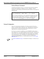
The vpshosts File
The vpshosts file identifies the MPS systems and other components associated
with a particular node. Typically, the file’s contents is the same across all nodes,
unless a particular node has unique components.
Each component listed in this file is identified by a component number, a component
type, and the name of the node where it resides. A node name specified as a dash (“-”)
implies the local node. Each component on the local node has a corresponding
subdirectory under $VPSHOME on Solaris systems, and under %VPSHOME% on NT
systems.
For example, if four MPS systems are defined in the vpshosts file, the following
subdirectories exist: $VPSHOME/vps1 (%VPSHOME%\vps1), vps2, vps3, and
vps4. Each MPS listed in the vpshosts file has it’s own set of configuration files
(e.g., vos.cfg, commgr.cfg, etc.) in the appropriate vpsN/etc directory.
The vpshosts file is automatically created or updated on a node when the system is
installed. A node only connects with those components defined in its vpshosts file.
The file might have to be manually edited for the MPS to connect with components
installed on other nodes.
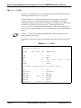
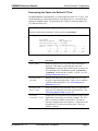
The following is an example of the vpshosts file:
Sample vpshosts File
$1
#
#vpshosts
#
#
This file was automatically generated by vhman.
#
Wed Apr 26 19:16:25 2000
#
# COMP
NODE
TYPE
110
vps
1
tmscomm
56
tms3003
vps
It is not necessary for every MPS node to have information about other nodes.
However, a PeriView workstation has to be configured with information for all nodes
that it will control. For specific information about the vpshosts file for use with
PeriView, see the Nortel Networks Media Processing Server Series PeriView
Reference Manual.
#P0988083 Ver. 1.0
Nortel Networks Confidential
Page 17
Nortel Networks Media Processing Server Series COMMGR Reference Manual
This page has been intentionally left blank.
Page 18
Nortel Networks Confidential
#P0988083 Ver. 1.0
3
2. Configuration and
Status Commands
This chapter covers:
1. Command syntax
2. Protocol configuration
3. Host availability and status
displays
4. Common configuration
parameters
Nortel Networks Media Processing Server Series COMMGR Reference Manual
3. Configuration and Status Commands
Command Syntax and Usage
The COMMGR process exists in all versions of the Nortel Networks Media
Processing Server Series (MPS). An MPS uses configuration commands to set up the
host communications software subsystem. These commands are intended to be issued
to the COMMGR process or protocol daemon from the commgr.cfg file during
system startup, while the host link is still down.
COMMGR status commands display information about the configuration and/or
current state of the software. Status commands can be issued from the VSH tool at
any time after system startup, with or without an active host link.
Configuration and status commands are identified to the command processor by the
keyword host. This is always followed by a number from 1 to 8 that specifies a
particular logical host. Each defined host has it its own set of configuration
commands. Commands that apply to one host do not affect the others.
The following is important information about issuing configuration and status
commands:
• In terms of syntax, most COMMGR configuration commands can also be issued
from the VSH command line. However, because some of the critical commands
are sequence dependent, and cannot be issued when the host is up, it is not
recommended that VSH be used for host configuration.
• In the commgr.cfg file, there must be a space between the keyword host and
the logical host number. On the command line, there must be no spaces between
host and the associated number.
• Multiple commands for a specific host can be included on the same line. If a
command string contains any errors, parsing of the string terminates at the point of
error, and any commands to the right of the error are not processed. Generally,
multiple-command strings should only be used for options applicable to all phone
lines.
• Protocol configuration also requires that certain protocol-specific commands be
issued from the daemon’s configuration file. (See The <protocol>.cfg File on
page 15.) These commands are documented in separate users guide manuals.
Page 20
Nortel Networks Confidential
#P0988083 Ver. 1.0
COMMGR Reference Manual
Configuration and Status Commands
Global Commands
Global configuration commands configure COMMGR functions that are applied to all
VTs. They use the following syntax:
host # <cmd1 [cmd2 [...]]> (entered in commgr.cfg)
host# <cmd1 [cmd2 [...]]> (entered from the VSH command tool)
Specifies a command/parameter for a defined host, where # is the host’s logical
number. Valid values are in the range 1-8. Using this syntax, the specified
command is applied to all applications in the system.
Virtual Terminal Range Commands
When a VT is associated with an application, the COMMGR assigns to it a unique
service identifier. Commands that configure the host software at the VT level can be
entered with a svcid range to apply the parameter values only to the specified
applications. Multiple commands can be specified on a single line if they have the
same host and svcid arguments.
To issue a command for a range of applications, use the following syntax:
host # svcid #[-#] <cmd1 [cmd2 [...]]> (commgr.cfg)
host # svcid all <cmd1 [cmd2 [...]]>
host#
host#
svcid #[-#] <cmd1 [cmd2 [...]]> (VSH tool)
svcid all <cmd1 [cmd2 [...]]>
Specifies a command/parameter for a single host, where # is the host’s logical
number. The syntax svcid #[-#] specifies a particular range of applications to
which the settings are applied. These applications must have service IDs that are
consecutively numbered. To apply the settings to all applications, use the syntax
svcid all.
When a command is issued that includes a svcid specification, internally, that VT
range is registered as the default VT range. If a svcid specification is omitted in a
command that normally accepts one, the new parameters are applied to the default VT
range. That is, the range for the new command is taken from the last command issued
that included a svcid specification.
#P0988083 Ver. 1.0
Nortel Networks Confidential
Page 21
Nortel Networks Media Processing Server Series COMMGR Reference Manual
Protocol Daemon Commands
Commands issued from the commgr.cfg file that configure the protocol daemon
(instead of the COMMGR) are called host parameter commands. For these
commands, all syntax parsing is performed by the protocol daemon. They require the
following syntax:
host # param[eter] "<cmd1 [cmd2 [...]]>" (commgr.cfg)
host# param[eter] "<cmd1 [cmd2 [...]]>" (VSH tool)
Sends a text string containing one or more configuration commands to the protocol
daemon, where # is the logical number of the host (1-8). Quotation marks are
required if the string contains any spaces for separating commands and/or
arguments. The keyword parameter can be abbreviated as param.
Protocol Configuration
There are two major protocol categories. For manager protocols, all necessary
software is contained within a single MPS system. This includes the main protocol
daemon (referred to as the protocol manager), the COMMGR process, and any
support processes associated with individual VTs.
For client/server protocols, each MPS has its own COMMGR client that connects
with a single protocol server daemon running on one specific system. This allows the
entire network to use a single bank of phone lines on one machine to provide better
access to the system VTs. Also, depending on the implementation, better reliability
can be had through load sharing. The number of expected COMMGR client
connections is specified in the vos.cfg file of the server node. (See The vos.cfg
File on page 14.)
See Protocol Architecture on page 6 for illustrations of manager vs. client/server systems.
Page 22
Nortel Networks Confidential
#P0988083 Ver. 1.0
COMMGR Reference Manual
Configuration and Status Commands
Manager-Type Protocol Configuration
A host is defined by a protocol name and whether or not it is asynchronous. The
following command specifies a manager-type protocol configuration for a particular
logical host:
host # protocol {atte [async] | vpstn3270 | cca_mgr |
appc_cm | geotel | iex}
Defines the host protocol type, by specifying the name of the protocol’s main
software process:
•
•
•
•
•
•
atte:
vpstn3270:
appc_cm:
cca_mgr:
geotel:
iex:
async, telnet, or VT100 emulation
3270 emulation
LU6.2 emulation
Credit Card Authorization (manager only)
GeoTel ICM
IEX TotalNet
This command must be included in the commgr.cfg file, as there is no default
value.
This command and the hostname/port commands are mutually exclusive. (See
Client/Server-Type Protocol Configuration on page 24.)
The async keyword is valid only for the ATTE-tty protocol. (ATTE-tty and
ATTE-telnet are distinctly different protocols.) The async parameter specifies
that the particular host requires asynchronous tty-type communications. By
default, a host is configured to be synchronous.
Examples:
host 1 protocol geotel
Specifies that the first host interfaces with a GeoTel ICM system (and
is non-asynchronous).
host 1 protocol atte async
Specifies that the first host is asynchronous and interfaces with an
ATTE-tty host.
In non-asynchronous host interaction, data transmissions are synchronized with start/
stop bits, and the keyboard is locked when data is sent to the host. The default mode
for non-async hosts is screen. (See Screen Mode on page 34.)
In asynchronous data transmissions, the sending and receiving of data is synchronized
by the use of control characters in the data stream. The keyboard is not locked, and
multiple send operations can be performed (instead of a send always being followed
by receive). The default mode is pace. (See 24-Byte Header and Pace Mode
Parameters on page 28.)
#P0988083 Ver. 1.0
Nortel Networks Confidential
Page 23
Nortel Networks Media Processing Server Series COMMGR Reference Manual
Client/Server-Type Protocol Configuration
In a client/server configuration, the protocol daemon acts as a server supporting multiple COMMGR connections. There is one COMMGR per MPS client, and each system has its own set of configuration files (i.e., commgr.cfg, vos.cfg, etc.).
To configure client/server systems, the protocol is not identified by name, but by the
location on the server system where it resides.
The following commands must exist in the commgr.cfg file of each client system to
configure the particular protocol. These commands should only be issued for
protocols implemented as client/server processes (i.e., these commands and the
protocol command are mutually exclusive).
host # hostname <host> port <#>
For server-type protocols, these two commands specify the location of the protocol
daemon server to which the local COMMGR connects. The specified host must be
one that is defined in the vpshosts file. (See The vpshosts File on page 17.)
The specified port number must be the one used by the server system for the daemon process, as specified in its vos.cfg file. (See The vos.cfg File on page 14.)
For a server protocol, these commands must be included in the commgr.cfg file,
as there are no defaults.
host # parameter "maxvt <#>"
Specifies the number of VTs to be supported by the COMMGR running on the
local client system. The server software cannot process any transactions from a
given COMMGR client until this parameter has been set.
Example:
host 1 hostname eagle port 4013
host 1 parameter "maxvt 20"
Specifies that the local COMMGR is to connect with the server process
running on the host named eagle, using port number 4013. The client
system supports up to 20 VTs.
Page 24
Nortel Networks Confidential
#P0988083 Ver. 1.0
COMMGR Reference Manual
Configuration and Status Commands
Host Session Assignment
An application can communicate with up to eight hosts, each of which can use a
different protocol. The protocol layer contains one or more logical definitions for
each physical host. A logical host definition consists of a host number, a protocol
identifier, and one or more protocol-specific processes. The same host can have
multiple logical definitions.
To switch communications from one host to another, an application issues a
session command from an ENVIRONMENT block, specifying the session number
of the particular host.
Each defined host is associated with a session number by the host # svcid #[-#]
session command. By default, a session number corresponds to a host’s logical
designation (e.g., host 1 is session 1, host 2 is session 2, etc.). This command can be
used to override the default session associations for a set of specified VTs or for all
VTs.
host # svcid #[-#] session <#>
Assigns a particular session number to the specified host #, for the applications
with the service IDs #[-#]. Valid values for the session number are 1 to 8.
In a multiple host environment, if one connection has headermode enabled and
another does not, it is necessary to issue the headermode command each time the
session is switched. (See Interacting with Multiple Hosts on page 30.)
#P0988083 Ver. 1.0
Nortel Networks Confidential
Page 25
Nortel Networks Media Processing Server Series COMMGR Reference Manual
Virtual Terminal Mapping
The set of Virtual Terminals are assigned to application phone lines by the
assignvt command.
host # svcid #[-#] assignvt <#>
Assigns the specified VT number (<#>) to the phone line(s). If a service ID range
is given, the first line in the range is assigned the VT denoted by <#>, and the subsequent lines are assigned the next set of VTs.
Example:
host 1 svcid 1-2 assignvt 3
Specifies that VT 3 is mapped to line 1 and VT 4 to line 2.
The following is important information about VT assignments:
• The number of assigned VTs cannot exceed the setting of the maxvt parameter.
For manager-type protocols, maxvt is set in the main protocol configuration file.
For client/server protocols, maxvt can be specified in the commgr.cfg file or
from an application. If issued from the file, the maxvt parameter must precede
the assignvt and session commands. If maxvt is given from an
application, the VT up condition has to be received before any other VT-related
commands are issued.
• These options do not apply to the GEOTEL process, which requires each phone
line to be assigned to the Virtual Terminal (VT) with the same numeric
designation (i.e., line 1 maps to VT 1, line 2 maps to VT2, etc.).
Page 26
Nortel Networks Confidential
#P0988083 Ver. 1.0
COMMGR Reference Manual
Configuration and Status Commands
Host Mode Configuration
The MPS can exchange messages with host systems in various formats. Typically, in
synchronous communications, the MPS sends and receives messages identical to those
that are sent to CRT terminals.
Alternatively, the MPS and host can exchange messages in 24-Byte Header or PACE
data stream format. This type of message exchange generally reduces the amount of
data exchanged. A disadvantage is that message interface software might have to be
specially implemented on the host.
The message exchange format for a specific host is defined by using the host mode
command:
host # mode {24 | pace | rawtty | screen}
Defines the host-MPS message format, where:
• 24 specifies 24-Byte Header mode. (See 24-Byte Header and Pace Mode
Parameters on page 28.)
• pace specifies PACE mode. (See 24-Byte Header and Pace Mode
Parameters on page 28.)
• rawtty specifies rawtty mode. (See Rawtty mode on page 34.)
• screen specifies screen mode. (See Screen Mode on page 34.)
The default host mode depends on whether or not the host is defined as asynchronous.
(See Host Mode Configuration on page 27.) For non-async host configurations, the
default mode is screen. If the host is specified as async, the default mode is pace.
The screen option is valid only for non-asynchronous hosts and rawtty is valid
only for async hosts.
#P0988083 Ver. 1.0
Nortel Networks Confidential
Page 27
Nortel Networks Media Processing Server Series COMMGR Reference Manual
24-Byte Header and Pace Mode Parameters
PACE (Periphonics Asynchronous Communications Exchange) is a format for data
stream message exchange that is flexible and extensible. It can be used with both the
3270 mode of operation and the async mode. For a async type host, PACE is the
default mode.
The term asynchronous, as used here, applies to the asynchronous nature of message
exchanges between systems, rather than link-level character synchronization.
For backward compatibility with earlier generations of equipment, the MPS has a
message exchange format called 24-Byte Header. In this format, a header 24 bytes in
length precedes the actual message data. The header consists of a message ID, phone
line number, status and control fields, etc.
Internally, the system converts the 24-Byte Header into a PACE structure. The
application program then processes the PACE commands. An application program
can be provided that implements the MPS portion of this message exchange.
The MPS COMMGR does not automatically send connect, disconnect, and ring
messages to a host in 24-Byte Header mode. Applications have to handle the
conditions for these phone line states and then issue the device-status call function to
send the data to the host.
Page 28
Nortel Networks Confidential
#P0988083 Ver. 1.0
COMMGR Reference Manual
Configuration and Status Commands
Transaction Codes and Status-Only Messages
Some commands valid for both the PACE and 24-Byte Header modes involve the
generation of transaction codes and status messages. Transaction codes are typically
used with teleprocessing monitor programs, such as IBM CICS. These codes precede
the input data and initiate specific transaction processing routines.
The following commands are for 24-Byte Header mode. Most of these commands
support a svcid #[-#] specification, which causes the settings to be applied to a
range of application VTs.
host # [svcid #[-#]] ctran {<trancode> | -}
Specifies a transaction code prepended by the system to all data messages sent from
the indicated applications to the host, where:
•
•
•
•
<trancode> is a string of up to 18 characters denoting the transaction code.
"-" is a special character that disables this function. This is the default.
# is the host number (1-8).
#[-#] is the phone line range.
host # [svcid #[-#]] stran {<trancode> | -}
Specifies a transaction code prepended by the system to all status-only messages
generated and sent by the system to the host (without any application involvement),
where:
•
•
•
•
<trancode> is a string of up to 18 characters denoting the transaction code.
- is a special character that disables this function. This is the default.
# is the host number (1-8).
#[-#] is the phone line range.
The stran and ctran parameters can be set by an application via an Environment
block to configure it’s own phone line. This overrides any settings made in the
commgr.cfg file. If an application sets one or both of these values, the settings
made to that line in the commgr.cfg file are not restored when the application exits.
#P0988083 Ver. 1.0
Nortel Networks Confidential
Page 29
Nortel Networks Media Processing Server Series COMMGR Reference Manual
Header Message Translation
In a 24-Byte Header mode or PACE environment, the translation of header messages
can be enabled or disabled. If headermode is enabled, the COMMGR translates the
header messages. If headermode is disabled, the application performs the translation.
The headermode parameter is applied to the phone line and not its associated
Virtual Terminal. Also, it is relevant only to hosts that support screen-type interaction,
and cannot be used with async hosts.
The headermode setting is typically issued from application Environment blocks.
Headermode is disabled only for the initial login screen and immediately re-enabled
after login is completed.
host # svcid #[-#] headermode {on | off}
Configures the translation of header message for 24-Byte Header or PACE hosts,
where:
• #[-#] are the service IDs for a range of applications.
• on enables message translation. This is the default.
• off disables translation.
Interacting with Multiple Hosts
For systems configured to interact with multiple hosts, if one host connection has
headermode enabled (for either PACE or 24-Byte Header) and another does not, it
is necessary to issue the headermode command each time the session command
is used to switch between them. (The headermode parameter applies to the phone
line and not its associated Virtual Terminal.)
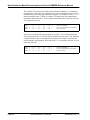
In the following example, host 1 is a screen host (i.e., no header is required) and host 2
uses 24-Byte Header mode:
Environment
Environment
:
Environment
Environment
session 1
headermode off
{sets the session to host 1}
{disables header translations}
session 2
headermode on
{sets the session to host 2}
{enables header translations}
Applications can switch between hosts as needed. (See Host Session Assignment on
page 25.)
Page 30
Nortel Networks Confidential
#P0988083 Ver. 1.0
COMMGR Reference Manual
Configuration and Status Commands
Host Login Headers
If a host connection uses headermode, in most cases, it must be disabled during the
login process.
Environment headermode off
login code
:
Environment headermode on
Send/Receive requests
{disables header translations}
{enables header translations}
{send transaction data to host}
24-Byte Header-Specific Parameters
Host Numeric Vocabulary Element Format
When running in 24-Byte Header mode, the MPS receives instructions from the host
(instead of the application) to determine which vocabulary elements are spoken to the
caller. The host references these elements by their numeric designations (i.e., the
vocabulary element numbers). The following command specifies the format that the
host uses to transmit element numbers. This command should be placed in the
commgr.cfg configuration file.
host # {wvocab | bvocab}
Selects the format of vocabulary item numbers returned from a 24-Byte Header
host, where:
• # is the host number (1-8).
• wvocab specifies that numbers are sent as words (i.e., two bytes).
• bvocab specifies that the numbers are sent as single bytes. This is the default.
If the vocabulary has more than 255 elements, wvocab must be set.
#P0988083 Ver. 1.0
Nortel Networks Confidential
Page 31
Nortel Networks Media Processing Server Series COMMGR Reference Manual
Call Referral Parameters
A host running in 24-Byte Header mode can send referral requests to the application.
The refer command sets the mode for the application’s phone line after the referral
has been established. This command should only be issued from the commgr.cfg
configuration file.
host # svcid #[-#] refer {input | output | hangup}
Sets a particular mode for the telephone line after referral bridging, where:
• #[-#] are the service IDs for a range of applications.
• input specifies that the line will wait for touchtone input after the referral is
established.
• output specifies that a voice prompt is to be sent to the referral line after the
referral is established.
• hangup specifies that the line is to be hung up after the referral is established.
A host running in 24-Byte Header mode can send a referral request to the application.
The rfno command is used to specify the referral number to be to outdialed. This
command should only be issued from the commgr.cfg configuration file.
host # svcid #[-#] rfno {<#> | -}
Sets the referral phone number in 24-Byte Header mode, where:
• #[-#] are the service IDs for a range of applications.
• <#> is the referral number. This can be up to 12 characters in length.
• “-”denotes a null telephone number. It is assumed that the host will supply the
number.
Page 32
Nortel Networks Confidential
#P0988083 Ver. 1.0
COMMGR Reference Manual
Configuration and Status Commands
Host Control of Voice Prompts
For backward compatibility, the appcode/noappcode command pair offers 24Byte Header functionality. With earlier equipment, voice prompts could be controlled
by the host computer. The host would send appcodes to the application that identified
the voice prompts to be spoken. Interpretation of the appcodes is the responsibility of
the application, which must be programmed to use the PARAM utility. These
commands should only be issued from the commgr.cfg configuration file.
host # svcid #[-#] {appcode | noappcode}
Denotes the presence or absence of PARAM appcodes in 24-Byte Header messages
from the host, where:
• #[-#] are the service IDs for a range of applications.
• appcode indicates the presence of appcodes in host messages.
• noappcode indicates that appcodes are not used.
Status Message Timestamp
A timestamp can be placed into status messages sent to the host in 24-Byte Header
mode. This is configured with the h9status command. This command should only
be issued from the commgr.cfg configuration file.
host # svcid #[-#] h9status {on | off}
Sets the status message timestamp sent in 24-Byte Header messages, where:
• #[-#] are the service IDs for a range of applications.
• on sets the timestamp to '9999'.
• off sets the timestamp to '0000', which is the default.
This command is functionally equivalent to the host 9status command in
previous versions of VOS.
#P0988083 Ver. 1.0
Nortel Networks Confidential
Page 33
Nortel Networks Media Processing Server Series COMMGR Reference Manual
Rawtty mode
In the async mode of operation, application-specific protocols can be used by
invoking the rawtty mode. In this mode, all host input is delivered to one phone line.
The application associated with that line implements the message-level protocol and
distributes the messages to the appropriate applications.
When running in rawtty mode, all host messages are sent only to the line associated
with the first Virtual Terminal. VT 1 can be assigned to any valid phone line.
One way to implement communication between the applications is to use shared
memory data cards. By assigning values to specific cards, any application that shares
these cards can access the data.
Output to the host can come from any application. No formatting is done by the
COMMGR software for messages in either direction (other than handling the standard
sol/eol envelope). System-level inquiry response logic is not provided in this mode.
The applications must perform this function explicitly if it is required.
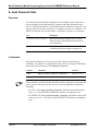
Screen Mode
MPS applications communicate with most screen mode hosts using screens
formatted to BMS (Basic Map Support) standards. To send data to the host, an
application supplies a formatted screen with data for the relevant fields. To acquire
input from the host, the application receives a formatted screen and reads the data
from its fields.
The PeriMap utility provides all functions necessary for defining the screens. In most
instances, when the MPS is installed, screens from existing data processing operations
can adapted for use by applications. (See the PeriProducer User’s Guide for more
information about creating and using maps.)
Screen mode cannot be used with asynchronous hosts. (See Manager-Type Protocol
Configuration on page 23.)
Page 34
Nortel Networks Confidential
#P0988083 Ver. 1.0
COMMGR Reference Manual
Configuration and Status Commands
Host Response Timers
The system provides several ways for an application to track the status of the host and
the timing of responses. For each phone line, the system maintains two timers that
measure the timing of a response to a query. These timers specify a maximum time
interval for the host response.
The enquiry response (er) timer is started when the application requests host input. If
the host fails to respond in the specified time interval, an ertimeout condition is
generated to the application, and the application handles it according to its
programming.
The intermediate (intime) timer works differently. It specifies a time interval,
which when elapsed, causes the system to speak out a special recorded message to the
caller. This is used to notify the caller that requested information is unavailable,
because the host has not yet responded to the query. This message spoken to the caller
is triggered by the operating system, as opposed to having applications generate it.
To activate this feature:
• Specify the time interval using the intime timer as described below.
• Specify the name of the vocabulary element to be spoken using either APPMAN
configuration parameters (see the PeriView Reference Manual) or by issuing the
Environment "intermsg" option from within the application.
• Record an appropriate message into the vocabulary element referenced by the text
string (e.g., “We are experiencing a temporary processing delay. Please hold on
or call back later.”) The default message says to the caller, “Please hold on.”
host # svcid #[-#] er <#>
Specifies a value for the enquiry response timer, where:
• #[-#] are the service IDs for a range of applications.
• <#> is value for the parameter specified in seconds. (Specify 0 to disable this
timer.)
host # svcid #[-#] intime <#>
Specifies a value for the intermediate timer. (Specify 0 to disable this timer.)
If the enquiry/response timer is to be used, the intime timer must be set to a value
lower than er in order to be effective.
#P0988083 Ver. 1.0
Nortel Networks Confidential
Page 35
Nortel Networks Media Processing Server Series COMMGR Reference Manual
Keyboard Status
In some circumstances, remote host applications can send premature keyboard unlock
instructions causing applications to perform RECEIVE TEXT/MAP operations
inappropriately. The unlocks command instructs the COMMGR to ignore a
specified number of unlocks following a SEND TEXT/MAP command before
actually unlocking the keyboard.
The unlocks command is specified for a range of phone lines.
host # svcid #[-#] unlocks <#>
Specifies the number of unlocks the COMMGR receives before unlocking the
keyboard. The number supplied as an argument must be between 1 and 100. The
default is 1.
Example:
host 1 svcid 3-5 unlocks 5
Instructs the COMMGR to wait for the fifth unlock after a SEND
TEXT/MAP operation before unlocking the keyboard.
The unlocks command sets an internal configuration parameter for the VTs in the
specified range. Each time a SEND TEXT/MAP is sent by COMMGR, the counter is
set to the specified unlocks value. For each subsequent unlock, the counter is
decremented, until it reaches 0, which unlocks the keyboard.
When this command is issued, the unlocks counter is reset to 0. If this is done
during a system operation, it can affect the counting of unlocks for any outstanding
SEND TEXT/MAP requests.
The status information displayed via the command host # svcid # status (see
Host/VT Status Information on page 55) indicates the value of the unlocks option and
the number of unlocks for which the COMMGR is currently waiting on the specified
line(s).
The option is not enabled for AID keys. That is, the first unlock after an AID key will
always unlock the keyboard.
Other COMMGR functions/failures that normally unlock the keyboard are as follows.
When any of these functions are used, the unlock counter is reset to 0:
• A message failure for a SEND TEXT/MAP.
• An AID key that unlocks the keyboard. (See AID Keys on page 37.)
• Changes in host/Virtual Terminal status.
Page 36
Nortel Networks Confidential
#P0988083 Ver. 1.0
COMMGR Reference Manual
Configuration and Status Commands
AID Keys
Attention Identifier keys (i.e., AID keys) are used for sending special terminal-type
keystrokes to the host, such as Program Function and Program Attention keys. The
set of valid host AID keys varies with the particular protocol. In some cases, these
keystrokes are equivalent to commands that send screen maps or text streams. AID
keys are usually issued by applications.
Generally, AID keys are issued from the command line only for testing
communications functions. To issue an AID key, use the following command:
host# [svcid #[-#]] aid <keyname>
Sends an AID key to the specified host. The specified <keyname> must be valid
for the selected protocol. Parentheses and quotation marks normally used to
delimit the keyname when sent from an application must not be included when
issued from the command line. This command can optionally be applied to a range
of VTs. If entered at the command line, there must be no spaces between the
keyword host and the host number.
Refer to the protocol features manuals for information about the specific set of AID
keys supported by each protocol.
!
Unless there is no other backward-compatibility alternative, the command AID lock
should never be issued from applications or from the command line. Unpredictable
and detrimental effects can occur if AID lock is issued.
Whenever a message, screen map, or SEND request is sent to a host from an
application, the default AID key is automatically sent with the data (unless another
AID key is specified by the application for that SEND operation). The default AID
key employed by the MPS depends on the specific host protocol. The following
command changes the default AID key.
host # aiddefault <keyname>
Changes the default AID key on a per-host basis, where <keyname> is an ASCII
string denoting the AID key.
The following AID keys must always be followed by issuing an AID IMMED
keystroke, regardless of the protocol being used: ACCEPT, ALLOCATE, CONNECT,
DEALLOCATE, DISCONNECT, and PF1-24.
#P0988083 Ver. 1.0
Nortel Networks Confidential
Page 37
Nortel Networks Media Processing Server Series COMMGR Reference Manual
Host Availability
The link to a host computer and associated communications equipment can experience
failure for a variety of reasons. The MPS can detect the state of the host link in several
ways depending on the protocol.
From the point of view of the COMMGR (and applications), a host is either available
or unavailable. If the host is available (i.e., the host link is in an up state) it can
exchange messages with MPS applications. When the host is unavailable (i.e., the
host link is in a down state), applications cannot communicate with it.
The system informs applications about host availability via status conditions. The
following command specifies whether or not applications receive these messages:
host # svcid #[-#] hostctl {on | off}
Enables or disables the passing of conditions to the applications, where:
• #[-#] is the service ID specification for an application or range of
applications.
• The parameter on specifies that conditions are generated to the applications. If
a problem renders the line without an available host, the application receives
the hctloff condition. When the host link comes back up, the htclon
condition is generated to the application, which will handle it according to its
programming.
• The parameter off disables the passing of conditions to the applications. This
is the default.
The following is important information regarding the status of host links:
• If an application is not configured for host interaction, the associated host link is
considered down.
• The COMMGR software cannot detect a loss of host services if the MPS
maintains data exchanges with the host, but the links to the application are no
longer available. Applications must be written to handle this possibility. (For
example, when using ATTE-telnet, a host down message indicates that the ATTE
process is not running and host up indicates that ATTE is running. The
COMMGR cannot determine if the telnet link is actually up or down.)
Page 38
Nortel Networks Confidential
#P0988083 Ver. 1.0
COMMGR Reference Manual
Configuration and Status Commands
Host Status Commands
Host availability can be determined at any time by issuing the following command
from the VSH tool:
host# status
Displays on-screen status information about the specified host.
Example:
vsh#mps.1 {1} -> host1 status
Host 1
-----Type
Mode
Protocol
Status
Aid
:
:
:
:
:
VOS Generic
screen
atte
Host down
enter
This sample status display for the node mps.1 indicates that host 1
is an ATTE-based host, which is currently down.
During normal operations, applications can determine the host status via the Get the
Host State function of the PeriProducer System block, or via host control status
messages. (See Host Availability on page 38.)
The following command displays information about the Virtual Terminals assigned to
the specified lines. Generally, this command is issued only from the VSH command
line.
host# svcid #[-#] read
Displays the contents of the screen buffers for the specified lines. This command is
valid only for hosts running in screen mode.
#P0988083 Ver. 1.0
Nortel Networks Confidential
Page 39
Nortel Networks Media Processing Server Series COMMGR Reference Manual
This page has been intentionally left blank.
Page 40
Nortel Networks Confidential
#P0988083 Ver. 1.0
4
3. Virtual Terminal
Configuration
This chapter covers:
1. Assigning VT(s) to
applications
2. VT pooling configuration
3. VT status information
4. Application programming
notes
Nortel Networks Media Processing Server Series COMMGR Reference Manual
4. Virtual Terminal (VT) Configuration
Virtual Terminal Overview
When communicating with an external host computer, most types of Nortel Networks
Media Processing Server Series (MPS) applications are treated by the host as an enduser terminal. Messages are sent to the application in the same manner as being
transmitted to a terminal screen. Messages sent from applications appear to the host
as if they were sent from a terminal’s keyboard.
Applications emulate the functions of a terminal operator by using Virtual Terminals
(VTs). Essentially, VTs are software and memory resources within the Media
Processing Server (MPS) that are allocated to applications either on a permanent or asneeded (i.e., pooled) basis. (See Virtual Terminal Pooling on page 44.)
To configure application-VT assignments, an application is associated with a
COMMGR service identifier. The service ID is used internally to map applications to
their respective VTs, configure an application’s host-related parameters, generate
reports, and debug host and MPS applications. Service identifiers are specified by
including the svcid keyword in commands. (See Virtual Terminal Range
Commands on page 21.)
The following is important information about the use of service identifiers:
• During run-time, the service identifier for an application is internally mapped to
the phone line on which it is running. Thus, a reference to a particular service
identifier denotes a specific application and phone line.
• The number of applications that can bind to COMMGR at one time is 512. This
limit cannot be altered. Valid COMMGR service identifiers range from 1 to 512.
Page 42
Nortel Networks Confidential
#P0988083 Ver. 1.0
COMMGR Reference Manual
Virtual Terminal Configuration
Virtual Terminal Assignments
The phrase Virtual Terminal assignment refers to host-application mapping. By
default, one-to-one assignments are made between applications and VTs, if the host is
not a pooled host and no VT assignment commands are issued. To change the default
mappings, use the following commands:
host # svcid #[-#] assignvt <vt#>
Assigns a single VT to a specific service identifier, or a set of VTs to a range of
service identifiers, where:
• # is the host number (1-8).
• #[-#] is the service identifier for one or more applications.
• <vt#> is the (starting) VT number (1-256).
host # svcid #[-#] unassignvt
Undoes the VT assignment for a single application or range of applications.
The following is important information about VT assignments:
• To change the host/VT with which it is communicating, the application must
either issue the session command as an Environment function (see Host
Session Assignment on page 25) or use Virtual Terminal pooling. (See Virtual
Terminal Pooling on page 44.)
• By default, if there are no pooling or assignvt commands in the commgr.cfg
file for a given host, each application is assigned a VT for that host in one-to-one
correspondence (i.e., VT 1 is assigned to the first application, VT 2 is assigned to
the second application, etc.). These default assignments are equivalent to having
assignvt commands for each application.
• For a given host, if any pooling or assignvt commands are specified in the
commgr.cfg file, the default assignments are not made.
• If a range of service IDs is specified in the assignvt command, the service ID
numbering begins with the starting VT and subsequent VTs are assigned
incrementally in ascending order. The service ID range must be a continuous
series (e.g., a specification of 1-3,5 is invalid).
• For an async hosts, VT assignments must be made in one-to-one correspondence.
• The following error message is displayed when an application attempts to send
data to the host, with an invalid VT assignment.
Wed Jul 17 09:39:40 <commgr> 11055 Severity 3 Mps <#>
Invalid vt number, async host only allowed 1 to 1 mapping
of vt to line.
#P0988083 Ver. 1.0
Nortel Networks Confidential
Page 43
Nortel Networks Media Processing Server Series COMMGR Reference Manual
Virtual Terminal Pooling
The VT pooling feature of the MPS allows flexible and dynamic allocation of VTs to
applications based on their service IDs. The VTs in the pool are allocated to and deallocated from applications as-needed, allowing them to be shared in a manner that
efficiently uses system resources.
When an application requires host access, it requests allocation of a VT from the pool.
When the VT is no longer required, the VT is freed by the application and returned to
the pool. If one of the VTs in the pool is down, the COMMGR can allocate a different
VT from the pool, if one is available.
VT pooling cannot be used with hosts defined as async (see Manager-Type Protocol
Configuration on page 23) and is valid for use only with hosts running in screen
mode (see Host Mode Configuration on page 27).
VTs from different hosts can be configured in the same VT pool and multiple pools
can be defined. However, no single-host VT can exist in more than one pool. The
following tables illustrate VT pooling configurations:
Configuration Type
Pool A
Pool(s)
Host(s)
Host 1
Host 2
Host 1
Host 2
Single
Single
VTs 1-12
----
----
----
Multiple
Single
VTs 1-6
----
VTs 7-12
----
Multiple
Multiple
VTs 1-6
VTs 1-6
VTs 7-12
VTs 7-12
Pool A
Example: Valid two-pool
configuration. Note that all VTs
defined for a specific host are
assigned to only one pool.
Pool B contains VTs from host 1
(VTs 1-4) that are already
assigned to Pool A.
Pool B
Host 1
Host 2
Host 1
Host 2
VTs 1-4
VTs 5-8
VTs 5-8
VTs 1-4
Pool A
Example: Invalid configuration.
Page 44
Pool B
Pool B
Host 1
Host 2
Host 1
Host 2
VTs 1-4
VTs 5-8
VTs 1-4
VTs 1-4
Nortel Networks Confidential
#P0988083 Ver. 1.0
COMMGR Reference Manual
Virtual Terminal Configuration
VT Allocation to Applications
If there is only one defined VT pool, an application always uses that pool as the
current pool. If multiple pools are defined, the application can allocate VTs from
different pools, by specifying which pool to use when it requests a VT. An application
can only allocate one VT from any single pool at one time.
A VT is allocated using the Environment getvt <poolname> command. If a VT is
successfully allocated, no condition is returned and the application continues
executing.
If a VT cannot be allocated (e.g., all VTs in the pool are in use, the timeout period
expires, the pool’s hosts is down, etc.), the hostfail condition is returned.
Generally, this condition should be handled for every Environment getvt command.
Upon failure, the application can attempt to allocate a VT from the same pool after a
brief pause, or after repeated attempts, the application could ask the caller to try
calling again later. If other pools are configured, the application can request a VT
from a different pool.
After a VT has been successfully allocated, the application can perform normal host
transactions (e.g., Send/Receive Text/Map, AID keys, etc.). The application should
then change the handling of the hostfail condition to manage host transaction
failures.
After the VT is allocated, the pool from which it came becomes the application's
current pool. The current pool can be changed with the Environment usepool
command. This command is needed after an Environment session command to use
a previously allocated pooled VT.
When the VT is no longer required, it should be returned to the same VT pool using
the Environment freevt command. If the application does not explicitly free the
VT with this command, the VT is freed by the system when the application ends its
current execution run.
While a VT is allocated to an application line, VT-specific parameters can be
dynamically changed using Environment parameter commands. The changes
affect only the current host session set by the usepool (or session) command. In
the Environment command, specify “$VT” in place of the VT number, which instructs
the COMMGR to insert the application’s VT number when the command is processed.
For more information about application Environment commands, see the
PeriProducer User’s Guide.
#P0988083 Ver. 1.0
Nortel Networks Confidential
Page 45
Nortel Networks Media Processing Server Series COMMGR Reference Manual
VT Pooling Configuration
The commands that configure VT pooling are issued from the commgr.cfg file. To
properly configure VT Pooling, perform the following steps:
•
•
•
•
Define the VT pools to be used by applications to the COMMGR.
Assign particular VTs to the defined pools.
Set each pool's timeout value for application-issued getvt requests.
Specify the access method for each pool.
After they have been defined, pools cannot be added or removed while the system is
online. Individual VTs can be dynamically assigned to and removed from defined
pools when the system is active, but this is generally not recommended. (See
Removing VTs from a Pool on page 53.)
!
Page 46
To ensure that VTs are returned to the pools from which they came, it is important that
applications terminate gracefully. In general, this means that they should terminate
under their own control or from PeriView. Never use the Solaris kill -9 command
or the Windows NT Task manager to remove an application from the system.
Nortel Networks Confidential
#P0988083 Ver. 1.0
COMMGR Reference Manual
Virtual Terminal Configuration
VT Pooling Commands
All commands for configuring VT pooling are issued using the following syntax.
After the first command of this format is issued, the host becomes a pooled host.
host # pool <poolname> [command]
Specifies a configuration command that is to be applied to the indicated VT pool.
This syntax is used to precede all VT pooling commands.
The following is important information regarding VT pooling commands:
• VT pooling is only valid for hosts that are configured as type non-async (see Host
Mode Configuration on page 27) and running in screen mode (see Host Mode
Configuration on page 27).
• The first time any host # pool <poolname> [command] is executed, the
specified pool becomes defined for the indicated host. Also, that pool is then
treated as the current pool, until another pooling command is issued that specifies
a different pool name.
• By default, if there are no pool or assignvt commands in the commgr.cfg
file for a given host, each physical phone line is assigned a VT for that host in a
one-to-one correspondence (i.e., VT 1 is assigned to phone line 1, VT 2 is
assigned to phone line 2, etc.). These default assignments are equivalent to having
assignvt commands for each application phone line. The default assignments
are made during system initialization.
• If any pool or assignvt commands are specified in the commgr.cfg file for
a given host, the default assignments are not made for that host.
• After it has been assigned to a pool, it can be removed using the remove_vt
command. (See host # pool remove_vt <#> on page 53.)
#P0988083 Ver. 1.0
Nortel Networks Confidential
Page 47
Nortel Networks Media Processing Server Series COMMGR Reference Manual
VT Pooling Assignment
To configure a VT pool, a list of VTs from one or more hosts is assigned to that pool
using the vtlist command in the commgr.cfg file:
host # pool <poolname> vtlist #[-#]
Assigns one VT or a range of VTs to a specific pool (poolname) for the indicated
host. The vtlist #[-#] parameter specifies a single VT or a range of VTs to be
assigned. If multiple VTs are to be assigned, they must be consecutively numbered.
In a multi-host configuration, VTs for each host can be assigned to the same pool(s).
If one of the hosts goes down, it’s VTs become unusable. However, the VTs for the
other hosts are still active, and thus the pool(s) can still be used.
The following is an example of a VT pooling assignment configuration produced by
the indicated excerpts from a sample commgr.cfg file:
Pool B
Pool A
Pool C
Host 1
Host 2
Host 1
Host 2
Host 1
Host 2
VTs 1-4
VTs 1-4
VTs 5-8
VTs 5-8
VTs 9-12
VTs 9-12
# DEFINE VT POOLS
#
# Define PoolA
host1 pool PoolA vtlist 1-4
host2 pool PoolA vtlist 1-4
# Define PoolB
host1 pool PoolB vtlist 5-8
host2 pool PoolB vtlist 5-8
# Define PoolC
host1 pool PoolC vtlist 9-12
host2 pool PoolC vtlist 9-12
Page 48
Nortel Networks Confidential
#P0988083 Ver. 1.0
COMMGR Reference Manual
Virtual Terminal Configuration
VT Pooling Timeout Value
The pool timeout value denotes the maximum amount of time an application waits for
a VT to be allocated. If this timer expires, the hostfail condition is generated to
the application. The value specified for this command is used for all VTs in the pool,
regardless of the host number specified in the command.
host # pool <poolname> pooltimeout <#>
Specifies the timeout value of application requests for the VTs in the pool specified
as the <poolname> parameter. This timer value (<#>) is specified in seconds and
must be between 0 and 300 inclusive. The default is 5 seconds.
The following is some important information regarding the use of this command:
• If pooltimeout is set to 0, a getvt request times out immediately if no VTs
are available.
• If a getvt request fails on the first try, a message can be played to the caller from
the application (e.g., to inform him or her of the delay), then the request can be
tried again.
VT Pooling Access Method
The VTs in a pool can be accessed by one of two methods: sequential or nonsequential. Regardless of the access method, the lowest numbered host in a pool is
always favored.
• Sequential access allocates the lowest numbered available VT to the requesting
line. As examples, if VTs 2 and 5 were both available, VT 2 would be assigned
upon the next request. If VT 2 from host 1 is available and VT 1 from host 2 is
available, VT 2 from host 1 is allocated first.
• Non-sequential access uses a queuing method of allocating VTs, often referred to
as the round robin technique. Here, a list of available VTs is maintained. Upon
request from an application, the first VT in the list is the one that is assigned.
When the VT is freed, it goes to the end of the list.
#P0988083 Ver. 1.0
Nortel Networks Confidential
Page 49
Nortel Networks Media Processing Server Series COMMGR Reference Manual
The access mode is set by the following command:
host # pool <poolname> {sequential | nonsequential}
Specifies the type of access that applications have to the VTs in the pool identified
by the <poolname> parameter.
• The sequential option specifies that the lowest numbered VT in the pool is
allocated to the requesting line.
• The nonsequential option uses a queuing technique, where the next
available VT is allocated regardless of its numeric designation. The default is
nonsequential.
Like sequential access, for nonsequential access, the next VT available from the
lowest numbered host is also allocated first. If all VTs from host 1 are allocated and a
VT from host 2 is available, the VT from host 2 is used. If VT 3 from host 1 then
becomes available, VT 3 from host 1 is assigned to the next requesting line, even if VT
2 from host 2 is available.
Nonsequential access generally equalizes VT usage. This is different than sequential
access, where the lower numbered VTs are used first and more often. In a
sophisticated data processing environment, host message traffic can be complex, and
using the same subset of VTs can create message backlogs that reduce the efficiency
of the overall system. Sequential access should be used only if these VTs can handle
the extra message traffic. Use nonsequential access if this is a relevant issue.
The following is an example of nonsequential pool access. In this example, the
available VTs are numbered 1, 2, 3, 4, and 5.
Page 50
Action
Available VTs
1. Initial state of pool.
12345
2. Three VTs are requested. VTs
1,2, and 3 are allocated.
45
3. VT 2 is freed by its line.
452
4. VT 3 is freed by its line.
4523
5. The next VT is requested.
523
6. VT 1 is freed by its line.
5231
7. VT 4 is freed by its line.
52314
Nortel Networks Confidential
#P0988083 Ver. 1.0
COMMGR Reference Manual
Virtual Terminal Configuration
Selecting the Current Pool
For systems with multiple defined pools, an application can specify which pool is the
current pool with the Environment block’s usepool command. This is necessary if
an application switches hosts during a transaction.
To use a previously allocated VT, the usepool command must be specified after the
Environment session command (see Host Session Assignment on page 25).
host # svcid #[-#] usepool <poolname>
Switches the current pool to the specified <poolname>. This command is
normally issued from applications on an as-needed basis. The host and service ID
numbers are only necessary if this command is issued from the commgr.cfg file
or command line.
If there is only one defined pool, the usepool command is never needed. The
current pool is always the only defined pool.
#P0988083 Ver. 1.0
Nortel Networks Confidential
Page 51
Nortel Networks Media Processing Server Series COMMGR Reference Manual
Example Configuration
The following example set of commands configures two VT pools with the indicated
characteristics:
Configuration for VT Pooling
Pool B
Pool A
Host 1
Host 2
Host 3
Host 1
Host 2
VTs 1-4
VTs 5-8
VTs 1-4
VTs 5-8
VTs 9-12
(10 second timeout,
sequential access)
(20 second timeout,
nonsequential access)
#
# Define the first pool - poola
#
# VTs 1-4 from host 1
host1 pool poola vtlist 1-4
#
# VTs 5-8 from host 2
host2 pool poola vtlist 5-8
#
# VTs 1-4 from host 3
host3 pool poola vtlist 1-4
#
# Set the timeout to 10 seconds
host1 pool poola pooltimeout 10
#
# Set the pool to sequential access
host1 pool poola sequential
#
# Define the second pool - poolb
#
# VTs 5-8 from host 1
host1 pool poolb vtlist 5-8
#
# VTs 1-4 from host 2
host2 pool poolb vtlist 1-4
#
# Set the timeout to 20 seconds
host1 pool poolb pooltimeout 20
#
# Set the pool to nonsequential access
host1 pool poolb nonsequential
Page 52
Nortel Networks Confidential
#P0988083 Ver. 1.0
COMMGR Reference Manual
Virtual Terminal Configuration
Removing VTs from a Pool
Although pool definitions cannot be changed once the system has been initialized (i.e.,
new pools cannot be added), individual VTs can be dynamically assigned and
removed from the existing pool(s). Upon removal from a pool, a VT is immediately
available to be assigned to a different (or the same) pool using the vtlist command.
(See host # pool <poolname> vtlist #[-#] on page 48.)
The following command is used to remove VTs from their assigned pools:
host # pool remove_vt <#>
Removes the VT indicated by <#> from the particular pool specified by the
<poolname> parameter.
The remove_vt command is intended for use only while the system is idle (i.e.,
when no calls are in progress). VT assignments should only be changed dynamically
to find optimal VT/pool assignments for equal pool usage. Once the optimal
assignments have been determined, modify the vtlist commands in commgr.cfg
to reflect these assignments. Note that the system must be rebooted for the changes in
commgr.cfg to take effect.
!
Using remove_vt while calls are in progress can result in a loss of host session for
the application.
The status of VT pools can be ascertained at anytime by entering the poolstatus
command at the VSH tool. (See Determining the Status of a Defined VT Pool on
page 57.)
#P0988083 Ver. 1.0
Nortel Networks Confidential
Page 53
Nortel Networks Media Processing Server Series COMMGR Reference Manual
The following is an example of removing a VT from a pool designated as poola
(originally containing VTs 1-4) and assigning it to poolb (originally containing VTs
5-7).
vsh.1 {20} host1 pool poola poolstatus
Pool Name
:
Allocation method
:
Allocation Wait Time :
Virtual Terminal List:
Host 1
:[
poola
Non-Sequential
5 seconds
VNum/Service ID
1/ - ], [ 2/ - ], [
3/ - ], [
4/ - ]
vsh.1 {21} host1 pool poola remove_vt 1
vsh.1 {22} host1 pool poola poolstatus
Pool Name
: poola
Allocation method
: Non-Sequential
Allocation Wait Time : 5 seconds
Virtual Terminal List: Num/Service ID
Host 1
:[ 2/ - ], [ 3/ - ], [
4/ - ]
vsh.1 {23} host1 pool poolb vtlist 1
vsh.1 {24} host1 pool poolb poolstatus
Pool Name
:
Allocation method
:
Allocation Wait Time :
Virtual Terminal List:
Host 1
:[
Page 54
poolb
Sequential
5 seconds
Num/Service ID
1/ - ], [ 5/ - ], [
Nortel Networks Confidential
6/ - ], [
7/ - ]
#P0988083 Ver. 1.0
COMMGR Reference Manual
Virtual Terminal Configuration
Virtual Terminal Status Information
The commands discussed in this section provide information about the system’s use of
VTs and VT pools.
Host/VT Status Information
If an application is using a pooled VT, status information can be obtained using the
following variation of the host# status command.
host# svcid # status
Displays status information, including VT configuration, for the application with
the specified service ID.
Examples:
vsh#mps.1 {1} -> host1 svcid 1 status
Host Service Id
1
------------------Acquired By
: <none>
Host Control : off
Timers
: er: 30 inter: 10
Aid
: enter
System mode
: Non Pooling
Sessioned Host: 1
VT# for Host 1: 1
VT status
: Keyboard Unlocked, No input,
VT up
Waiting for 1 unlocks, 0 left
vsh#mps.1 {1} -> host1 svcid 1 status
Host Service Id
1
------------------Acquired By
: acquire (cd: 9 handle: 2)
Host Control : off
Timers
: er: 30 inter: 10
Aid
: enter
System mode
: Non Pooling
Sessioned Host: 1
VT# for Host 1: 1
VT status
: Keyboard Unlocked, No input,
VT up
Waiting for 1 unlocks, 0 left
#P0988083 Ver. 1.0
Nortel Networks Confidential
Page 55
Nortel Networks Media Processing Server Series COMMGR Reference Manual
Page 56
Field
Description
Host Service Id
Service ID of the application for which status
information is displayed.
Acquired By
Internal MPS information about the particular
application.
Host Control
Status of host messages to the application. This is
shown as either on or off. This is set by the
hostctl command. (See Keyboard Status on page
36.)
Timers
Shows the values of the enquiry-response and
intermediate timers, which are set using the er and
inter commands. (See Host Response Timers on
page 35.)
Aid
Default AID key for the host. (See AID Keys on page
37.)
System mode
Whether or not the application is using VT pooling.
Sessioned Host
The logical designation of the current host.
VT# for Host 1
Numeric designation of the VT used by the application
to interface with the host. If there is no VT currently
associated with the application’s service ID, the word
<none> is displayed.
VT Status
General information about the current state of the VT.
Nortel Networks Confidential
#P0988083 Ver. 1.0
COMMGR Reference Manual
Virtual Terminal Configuration
Determining the Status of a Defined VT Pool
The poolstatus command allows you to determine the status of a VT pool. This
command displays pooling information for all poolable hosts (i.e., non-async hosts
running in screen mode). The information list is blank for each host that has no
VTs allocated to the pool.
host # pool <poolname> poolstatus
Displays configuration parameters for the specified <poolname>.
Example:
vsh#mps.1 {2} -> host1 pool poola poolstatus
Pool Name
:
Allocation method
:
Allocation Wait Time :
Virtual Terminal List:
Host 1 : 1/ - ,
2/
: 6/ - ,
7/
: 11/ - , 12/
: 16/ - ,[ 17/
#P0988083 Ver. 1.0
poola
Non-Sequential
5 seconds
VT Num/Service ID
- ,
3/ - ,
4/
- ,
8/ - ,
9/
- ,
13/ - ,
14/
- ],[ 18/ - ],[ 19/
-
,
5/ - ,
,
10/ - ,
,
15/ - ,
],[ 20/ - ]
Field
Description
Pool Name
Shows the particular pool for which status information is
displayed. This name is specified by the user in the
<poolname> parameter and is defined to the system by the
first command of the form host # pool <poolname>
[command] issued from the commgr.cfg file. (See VT
Pooling Commands on page 47.)
Allocation
method
Indicates the method used to allocate individual VTs from
the pool to requesting applications. There are two methods:
sequential and nonsequential. (See VT Pooling Access
Method on page 49.)
Allocation
Wait Time
Shows the amount of time allotted to satisfy an application’s
request for VT allocation before the system times out. (See
VT Pooling Timeout Value on page 49.)
Virtual
Terminal List
Displays the VTs assigned to the specified pool and to which
applications (if any) they are currently assigned. The VTs
that are currently available are listed first. VTs that are
currently assigned to lines are listed next. At the end are the
designations of VTs that are currently down. (These are
shown in brackets.)
Nortel Networks Confidential
Page 57
Nortel Networks Media Processing Server Series COMMGR Reference Manual
The available VTs are listed according to their allocation method (i.e., sequential or
nonsequential.) If the pool uses sequential access, after an application frees a VT, it is
returned to the pool in the proper numerical sequence. For example, assume VT 1 is
allocated and then freed. The list of available VTs displayed by the poolstatus
command is illustrated below. This example assumes that there is one host with four
VTs assigned to the pool:
Host 1 : 1/ -, 2/ -, 3/ -, 4/ -0
Host 1 : 2/ -, 3/ -, 4/ -, 1/ 2
Host 1 : 1/ -, 2/ -, 3/ -, 4/ -
{VT 1 is available.}
{VT 1 is allocated to service ID 2.}
{VT 1 is freed.}
If the pool is configured for nonsequential access, after a VT is allocated and freed
from an application, the VT becomes the last available one in the pool. The following
example uses the same pool configuration as the previous example, except that the
access method is nonsequential. Note that when VT 1 is returned to the pool, it is put
at the end of the list:
Host 1 : 1/ -, 2/ -, 3/ -, 4/ Host 1 : 2/ -, 3/ -, 4/ -, 1/ 2
Host 1 : 2/ -, 3/ -, 4/ -, 1/ -
Page 58
Nortel Networks Confidential
{VT 1 is available.}
{VT 1 is allocated to service ID 2.}
{VT 1 is freed.}
#P0988083 Ver. 1.0
COMMGR Reference Manual
Virtual Terminal Configuration
Displaying VT Pooling Statistics
To display the number of times the VTs associated with a particular host and pool
have been successfully allocated to application lines, issue the poolrequest
command. This command shows status information including the numeric
designations of the VTs in the specified pool and the number of times each has been
successfully used.
Rebooting the system resets the allocation statistics to 0.
host # pool <poolname> poolrequest
Displays status information about the VTs in the specified pool (<poolname>)
pertaining to the number of successful application requests for the VTs.
Example:
vsh#mps.1 {3} -> host1 pool poola poolrequest
Pool Name
:
Allocation method
:
Allocation Wait Time :
Virtual Terminal List:
Host 1
:
:
:
:
#P0988083 Ver. 1.0
poola
Non-Sequential
5 seconds
VT Num-VT Req
1-9, 2-4, 3-5, 4-6, 5-6,
6-6, 7-4, 8-1, 9-8, 10-4,
11-3, 12-5, 13-6, 14-2, 15-6,
16-2, 17-6, 18-4, 19-9, 20-4
Field
Description
Pool Name
Shows the particular pool for which status information is
displayed. This name is specified by the user in the
<poolname> parameter and is defined to the system by the
first command of the form host # pool <poolname>
[command] issued from the commgr.cfg file. (See VT
Pooling Commands on page 47.)
Allocation
method
Indicates the method used to allocate individual VTs from
the pool to requesting applications. There are two methods:
sequential and nonsequential. (See VT Pooling Access
Method on page 49.)
Allocation
Wait Time
Shows the amount of time allotted to satisfy an application’s
request for VT allocation before the system times out. (See
VT Pooling Timeout Value on page 49.)
Nortel Networks Confidential
Page 59
Nortel Networks Media Processing Server Series COMMGR Reference Manual
Field
Description
Virtual
Terminal List
Displays information about the VTs in the specified pool in
the format xx - yy, where xx denotes the number of a
particular VT and yy indicates the number of times it has
been used by applications. For nonsequential access, the
number of successful allocations for each VT should be
fairly equal within each host grouping. A VT with an
unusually low number of successful allocations might not be
operating properly. In general, for sequential access, the
lower-numbered VTs for each host will have more
allocations than the higher-numbered VTs for that host.
However, this depends on factors such as system load and
the specific uses of applications.
Resetting VT Pooling Statistics
To reset the allocation statistics shown in the poolrequest report, use the
following command:
host # pool <poolname> poolinitrequest
Resets the allocation statistics. This is useful in determining VT usage profiles
during selected time periods.
The following is important information about VT Pooling statistics:
• After rebooting, if host 1 is defined and is a pooled host, any host 1 svcid ##
status commands show the system mode as "Pooling". For all other hosts
(even if there is no host 1), the System mode is displayed as "Non-pooling"
and the Sessioned Host is displayed as "1".
• A service identifier must be explicitly associated with a host session (either by
means of the host # session command on the console or an Environment
session command in the application) to display the currently assigned VT (if
any) in the host # svcid ## status command (unless the default to session
1, as described above, has occurred).
Page 60
Nortel Networks Confidential
#P0988083 Ver. 1.0
A
Host Character Sets
(LU6.2, VPSTN3270)
This chapter covers:
1. EBCDIC for LU6.2
2. EBCDIC for VPSTN3270
Nortel Networks Media Processing Server Series COMMGR Reference Manual
A. Host Character Sets
Overview
On a Nortel Networks Media Processing Server Series (MPS) system, character set
conversion tables can be tailored for host computers and applications that use the
LU6.2 or VPSTN3270 protocols. This entails having two character set map files. For
Solaris systems, the files are stored in the $VPSHOME/common/etc directory: For
Win/NT systems, the files are stored in the %VPSHOME%\common\etc directory.
File
Description
<charset>.2host.charset
Maps the local node character set to a custom
character set for outbound data transmissions to
the external host.
<charset>.2local.charset
Maps inbound data transmissions from the
external host to the local node’s character set.
Commands
The particular character set to be used is specified with one of the following
commands. Use whichever is appropriate for the protocol, specifying the identifying
portion of the file pair names as the <charset> argument.
Protocol
Command
Location
LU6.2
appc_cm host_charset <charset>
appc_cm.cfg
VPSTN3270
vpstn3270 host_charset <charset>
vpstn3270.cfg
If the command is not entered in the indicated location, it might not be executed in the
proper sequence with respect to other necessary position-dependent configuration
commands:
• For LU6.2, if the appc_cm host_charset command is not specified in the
appc_cm.cfg file, the Brixton EBCDIC character set mapping is used.
• For VPSTN3270, if the vpstn3270 host_charset command is not specified
in the vpstn3270.cfg file, the original VPSTN3270 character set mapping is
used.
Page 62
Nortel Networks Confidential
#P0988083 Ver. 1.0
COMMGR Reference Manual
Host Character Sets
File Format
The character set mapping files are set up such that the order of the hexadecimal
values in the 2local file matches the corresponding values in the host character set,
and the order of the hex values in the 2host file matches the corresponding values in
the local node’s character set. To perform the conversion, the local node character
value is used as an index into the list of values in the 2host file to find the
corresponding character in the host’s character set, and vice versa.
Additionally, the file format must adhere to the following rules:
• Lines that start with "#" are comments. The "#" must be the first character on
the line.
• The character set is specified as a series of two-digit hexadecimal values.
• Lines that are not comments can only contain a list of hex values.
• There must be exactly 256 values in the file. Any more or less will cause errors.
The following are the results if the file identified in the host_charset command
contains errors:
• For LU6.2, any errors in the specified file result in the immediate termination of
the APPC_CPI process. Information about the error is written to the
alarm.log file.
• For VPSTN3270, any errors in the specified file results in the system using the
original VPSTN3270 character set mapping.
#P0988083 Ver. 1.0
Nortel Networks Confidential
Page 63
Nortel Networks Media Processing Server Series COMMGR Reference Manual
Sample Files
The following are examples of two EBCDIC US character set files suitable for use
with the LU6.2 and VPSTN3270 protocols.
Sample ebcdic-us.2host.charset File
#
# ebcdic-us.2host.charset
#
# This character set is used when Host is using ebcdic-us
# character set and local node is using ascii character set.
# This charset is used to map local ascii charset to host
# ebcdic-us charset.
#
# ascii to ebcdic-us mapping
#
#
# 00 - 1f All these map to EBCDIC blanks.
40 40 40 40 40 40 40 40 40 40 40 40 40 40 40 40
40 40 40 40 40 40 40 40 40 40 40 40 40 40 40 40
# 20 - 2f
40 5a 7f 7b 5b 6c 50 7d 4d 5d 5c 4e 6b 60 4b 61
# 30 - 3f
f0 f1 f2 f3 f4 f5 f6 f7 f8 f9 7a 5e 4c 7e 6e 6f
# 40 - 4f
7c c1 c2 c3 c4 c5 c6 c7 c8 c9 d1 d2 d3 d4 d5 d6
# 50 - 5f
d7 d8 d9 e2 e3 e4 e5 e6 e7 e8 e9 40 e0 40 40 6d
# 60 - 6f
79 81 82 83 84 85 86 87 88 89 91 92 93 94 95 96
# 70 - 7f
97 98 99 a2 a3 a4 a5 a6 a7 a8 a9 c0 6a d0 a1 40
# 80 - 9f All these map to EBCDIC blanks.
40 40 40 40 40 40 40 40 40 40 40 40 40 40 40 40
40 40 40 40 40 40 40 40 40 40 40 40 40 40 40 40
# a0 - af
40 40 4a 40 40 40 6a 40 40 40 40 40 5f 40 40 40
# b0 - ff All these map to EBCDIC blanks.
40 40 40 40 40 40 40 40 40 40 40 40 40 40 40 40
40 40 40 40 40 40 40 40 40 40 40 40 40 40 40 40
40 40 40 40 40 40 40 40 40 40 40 40 40 40 40 40
40 40 40 40 40 40 40 40 40 40 40 40 40 40 40 40
40 40 40 40 40 40 40 40 40 40 40 40 40 40 40 40
# End-of-file
Page 64
Nortel Networks Confidential
#P0988083 Ver. 1.0
COMMGR Reference Manual
Host Character Sets
Sample ebcdic-us.2local.charset File
#
# ebcdic-us.2local.charset
#
# This character set is used when Host is using ebcdic-us
# character set and local node is using ascii character set.
# This charset is used to map host ebcdic-us charset to local
# ascii charset.
#
# ebcdic-us to ascii mapping
#
#
#
# 00 - 0f
20 20 20 20 20 20 20 20 20 20 20 20 20 20 20 20
# 10 - 1f
20 20 20 20 20 20 20 20 20 20 20 20 20 20 20 20
# 20 - 2f
20 20 20 20 20 20 20 20 20 20 20 20 20 20 20 20
# 30 - 3f
20 20 20 20 20 20 20 20 20 20 20 20 20 20 20 20
# 40 - 4f
20 20 20 20 20 20 20 20 20 20 a2 2e 3c 28 2b 20
# 50 - 5f
26 20 20 20 20 20 20 20 20 20 21 24 2a 29 3b ac
# 60 - 6f
5F 2F 20 20 20 20 20 20 20 20 7C 2c 25 5f 3e 3f
# 70 - 7f
20 20 20 20 20 20 20 20 20 60 3a 23 40 27 3d 22
# 80 - 8f
20 61 62 63 64 65 66 67 68 69 20 20 20 20 20 20
# 90 - 9f
20 6a 6b 6c 6d 6e 6f 70 71 72 20 20 20 20 20 20
# a0 - af
20 7e 73 74 75 76 77 78 79 7a 20 20 20 20 20 20
# b0 - bf
20 20 20 20 20 20 20 20 20 20 20 20 20 20 20 20
# c0 - cf
7B 41 42 43 44 45 46 47 48 49 20 20 20 20 20 20
# d0 -df
7D 4A 4B 4C 4D 4E 4F 50 51 52 20 20 20 20 20 20
# e0 - ef
5C 20 53 54 55 56 57 58 59 5A 20 20 20 20 20 20
# f0 - ff
30 31 32 33 34 35 36 37 38 39 20 20 20 20 20 20
#End-of-file
#P0988083 Ver. 1.0
Nortel Networks Confidential
Page 65
Nortel Networks Media Processing Server Series COMMGR Reference Manual
This page has been intentionally left blank.
Page 66
Nortel Networks Confidential
#P0988083 Ver. 1.0
Index
Nortel Networks Media Processing Server Series COMMGR Reference Manual
Index
Configuration Commands
host # 13, 16, 20, 21
aid 37
aiddefault 37
async 23
bvocab 31
ctran 29
hostname 24
mode
24 27
pace 27
rawtty 27
screen 27
pool 47
nonsequential 50
poolinitrequest 60
poolrequest 59
poolstatus 54, 57
pooltimeout 49
remove_vt 53
sequential 50
vtlist 48
port 24
protocol 23
session 60
status 39
stran 29
wvocab 31
host # parameter 22
maxvt 24
host # svcid #[-#] 21
aid 37
appcode 33
assignvt 26, 43
ctran 29
er 35
h9status 33
headermode 30, 31
hostctl 38
intime 35
noappcode 33
read 39
refer 32
rfno 32
session 25, 30, 51
status 55
stran 29
unassignvt 43
unlocks 36
usepool 51
A
applications
Environment commands 25, 30, 35, 43, 45, 60
host control status messages. See host
communications, status messages.
RECEIVE TEXT/MAP 36
SEND TEXT/MAP 36
service ID 21
Virtual Terminals. See Virtual Terminals (VTs),
assignment to application service ID.
Attention Identifier (AID) keys
default AID key 37
keystroke emulation 37
B
Basic Map Support (BMS) 34
C
COMMGR system process 12, 13, 28, 30, 34, 44, 45
commgr.cfg file.
See configuration files, commgr.cfg.
configuration commands
parsing 13
syntax 20–22
Page 68
Nortel Networks Confidential
P0988083 Ver. 1.0
Nortel Networks Media Processing Server Series COMMGR Reference Manual
M
configuration files
commgr.cfg 13, 20–22
host#.rc 16
vos.cfg 12, 14
vpshosts 17
MPS
network environment 17
network nodes 12, 14, 17
P
D
Periphonics Asynchronous Communications
Exchange (PACE) mode. See host mode, PACE.
document
organization viii
stylistic conventions ix
POS port device 9
G
R
GeoTel
enterprise network 2
rawtty mode. See host mode, rawtty.
S
H
screen mode. See host mode, screen.
host communications
availability of host link 38
enquiry/response timer 35
header messages 30
intermediate timer 35
message exchange configuration 27
message format. See Host mode.
multiple host environment 13, 21
selecting the host session 25, 43, 45
state of host link 38
status messages 29, 38
transaction codes 29, 38
Virtual Terminals See Virtual Terminals (VTs).
SDLC 9
host mode 27
24-Byte Header 28–33
appcodes 33
call referrals 32
device-status call function 28
numeric vocabulary format 31
status message timestamp 33
PACE 28–30
rawtty 27, 34
screen 27, 34, 44
host type
async 23, 34
generic 34
non-async 23
protocol specifier 23
T
TCP/IP 9, 14
port number 14
Token Ring 9
24-Byte Header mode. See Host mode, 24-Byte
Header.
V
Virtual Terminals (VTs)
application commands 45
application design considerations 49
assignment to application service ID 43
command syntax 47
configuration of 46
default range 15
keyboard unlock signal 36
symbolic representation of VT number 45
VT Pooling 44–60
assigning VTs to pools 47–48, 57
defining VT pools 47
displaying status information 54, 55–60
examples of 44, 48, 52
multiple pool configuration 44, 48, 52
removing VTs from defined pools 53–54
resetting VT pooling statistics 60
sequential vs. nonsequential access 49–52,
57
VT request timeout 49, 57
Page 69
Nortel Networks Confidential
P0988083 Ver. 1.0
Nortel Networks Media Processing Server Series COMMGR Reference Manual
vocabulary functions
host vocabulary control 33
Please hold on message 35
VOS (Voice Operating Software)
configuration 12, 14
processes 4–5
X
X.25 9
Page 70
Nortel Networks Confidential
P0988083 Ver. 1.0