1
BayRS Version 15.0
Part No. 308645-15.0 Rev 00
June 2001
600 Technology Park Drive
Billerica, MA 01821-4130
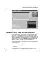
Configuring Traffic Filters and
Protocol Prioritization
Copyright © 2001 Nortel Networks
All rights reserved. June 2001.
The information in this document is subject to change without notice. The statements, configurations, technical data,
and recommendations in this document are believed to be accurate and reliable, but are presented without express or
implied warranty. Users must take full responsibility for their applications of any products specified in this document.
The information in this document is proprietary to Nortel Networks Inc.
The software described in this document is furnished under a license agreement and may only be used in accordance
with the terms of that license. The software license agreement is included in this document.
Trademarks
Nortel Networks, the Nortel Networks logo, the Globemark, ASN, BayRS, BayStack, BCC, BCN, BLN, and Passport
are trademarks of Nortel Networks.
Adobe and Acrobat Reader are trademarks of Adobe Systems Incorporated.
Restricted Rights Legend
Use, duplication, or disclosure by the United States Government is subject to restrictions as set forth in subparagraph
(c)(1)(ii) of the Rights in Technical Data and Computer Software clause at DFARS 252.227-7013.
Notwithstanding any other license agreement that may pertain to, or accompany the delivery of, this computer
software, the rights of the United States Government regarding its use, reproduction, and disclosure are as set forth in
the Commercial Computer Software-Restricted Rights clause at FAR 52.227-19.
Statement of Conditions
In the interest of improving internal design, operational function, and/or reliability, Nortel Networks Inc. reserves the
right to make changes to the products described in this document without notice.
Nortel Networks Inc. does not assume any liability that may occur due to the use or application of the product(s) or
circuit layout(s) described herein.
Portions of the code in this software product may be Copyright © 1988, Regents of the University of California. All
rights reserved. Redistribution and use in source and binary forms of such portions are permitted, provided that the
above copyright notice and this paragraph are duplicated in all such forms and that any documentation, advertising
materials, and other materials related to such distribution and use acknowledge that such portions of the software were
developed by the University of California, Berkeley. The name of the University may not be used to endorse or
promote products derived from such portions of the software without specific prior written permission.
SUCH PORTIONS OF THE SOFTWARE ARE PROVIDED “AS IS” AND WITHOUT ANY EXPRESS OR
IMPLIED WARRANTIES, INCLUDING, WITHOUT LIMITATION, THE IMPLIED WARRANTIES OF
MERCHANTABILITY AND FITNESS FOR A PARTICULAR PURPOSE.
In addition, the program and information contained herein are licensed only pursuant to a license agreement that
contains restrictions on use and disclosure (that may incorporate by reference certain limitations and notices imposed
by third parties).
ii
308645-15.0 Rev 00
Nortel Networks Inc. Software License Agreement
NOTICE: Please carefully read this license agreement before copying or using the accompanying software or
installing the hardware unit with pre-enabled software (each of which is referred to as “Software” in this Agreement).
BY COPYING OR USING THE SOFTWARE, YOU ACCEPT ALL OF THE TERMS AND CONDITIONS OF
THIS LICENSE AGREEMENT. THE TERMS EXPRESSED IN THIS AGREEMENT ARE THE ONLY TERMS
UNDER WHICH NORTEL NETWORKS WILL PERMIT YOU TO USE THE SOFTWARE. If you do not accept
these terms and conditions, return the product, unused and in the original shipping container, within 30 days of
purchase to obtain a credit for the full purchase price.
1. License grant. Nortel Networks Inc. (“Nortel Networks”) grants the end user of the Software (“Licensee”) a
personal, nonexclusive, nontransferable license: a) to use the Software either on a single computer or, if applicable, on
a single authorized device identified by host ID, for which it was originally acquired; b) to copy the Software solely
for backup purposes in support of authorized use of the Software; and c) to use and copy the associated user manual
solely in support of authorized use of the Software by Licensee. This license applies to the Software only and does not
extend to Nortel Networks Agent software or other Nortel Networks software products. Nortel Networks Agent
software or other Nortel Networks software products are licensed for use under the terms of the applicable Nortel
Networks Inc. Software License Agreement that accompanies such software and upon payment by the end user of the
applicable license fees for such software.
2. Restrictions on use; reservation of rights. The Software and user manuals are protected under copyright laws.
Nortel Networks and/or its licensors retain all title and ownership in both the Software and user manuals, including
any revisions made by Nortel Networks or its licensors. The copyright notice must be reproduced and included with
any copy of any portion of the Software or user manuals. Licensee may not modify, translate, decompile, disassemble,
use for any competitive analysis, reverse engineer, distribute, or create derivative works from the Software or user
manuals or any copy, in whole or in part. Except as expressly provided in this Agreement, Licensee may not copy or
transfer the Software or user manuals, in whole or in part. The Software and user manuals embody Nortel Networks’
and its licensors’ confidential and proprietary intellectual property. Licensee shall not sublicense, assign, or otherwise
disclose to any third party the Software, or any information about the operation, design, performance, or
implementation of the Software and user manuals that is confidential to Nortel Networks and its licensors; however,
Licensee may grant permission to its consultants, subcontractors, and agents to use the Software at Licensee’s facility,
provided they have agreed to use the Software only in accordance with the terms of this license.
3. Limited warranty. Nortel Networks warrants each item of Software, as delivered by Nortel Networks and properly
installed and operated on Nortel Networks hardware or other equipment it is originally licensed for, to function
substantially as described in its accompanying user manual during its warranty period, which begins on the date
Software is first shipped to Licensee. If any item of Software fails to so function during its warranty period, as the sole
remedy Nortel Networks will at its discretion provide a suitable fix, patch, or workaround for the problem that may be
included in a future Software release. Nortel Networks further warrants to Licensee that the media on which the
Software is provided will be free from defects in materials and workmanship under normal use for a period of 90 days
from the date Software is first shipped to Licensee. Nortel Networks will replace defective media at no charge if it is
returned to Nortel Networks during the warranty period along with proof of the date of shipment. This warranty does
not apply if the media has been damaged as a result of accident, misuse, or abuse. The Licensee assumes all
responsibility for selection of the Software to achieve Licensee’s intended results and for the installation, use, and
results obtained from the Software. Nortel Networks does not warrant a) that the functions contained in the software
will meet the Licensee’s requirements, b) that the Software will operate in the hardware or software combinations that
the Licensee may select, c) that the operation of the Software will be uninterrupted or error free, or d) that all defects
in the operation of the Software will be corrected. Nortel Networks is not obligated to remedy any Software defect that
cannot be reproduced with the latest Software release. These warranties do not apply to the Software if it has been
(i) altered, except by Nortel Networks or in accordance with its instructions; (ii) used in conjunction with another
vendor’s product, resulting in the defect; or (iii) damaged by improper environment, abuse, misuse, accident, or
negligence. THE FOREGOING WARRANTIES AND LIMITATIONS ARE EXCLUSIVE REMEDIES AND ARE
IN LIEU OF ALL OTHER WARRANTIES EXPRESS OR IMPLIED, INCLUDING WITHOUT LIMITATION ANY
WARRANTY OF MERCHANTABILITY OR FITNESS FOR A PARTICULAR PURPOSE. Licensee is responsible
308645-15.0 Rev 00
iii
for the security of its own data and information and for maintaining adequate procedures apart from the Software to
reconstruct lost or altered files, data, or programs.
4. Limitation of liability. IN NO EVENT WILL NORTEL NETWORKS OR ITS LICENSORS BE LIABLE FOR
ANY COST OF SUBSTITUTE PROCUREMENT; SPECIAL, INDIRECT, INCIDENTAL, OR CONSEQUENTIAL
DAMAGES; OR ANY DAMAGES RESULTING FROM INACCURATE OR LOST DATA OR LOSS OF USE OR
PROFITS ARISING OUT OF OR IN CONNECTION WITH THE PERFORMANCE OF THE SOFTWARE, EVEN
IF NORTEL NETWORKS HAS BEEN ADVISED OF THE POSSIBILITY OF SUCH DAMAGES. IN NO EVENT
SHALL THE LIABILITY OF NORTEL NETWORKS RELATING TO THE SOFTWARE OR THIS AGREEMENT
EXCEED THE PRICE PAID TO NORTEL NETWORKS FOR THE SOFTWARE LICENSE.
5. Government licensees. This provision applies to all Software and documentation acquired directly or indirectly by
or on behalf of the United States Government. The Software and documentation are commercial products, licensed on
the open market at market prices, and were developed entirely at private expense and without the use of any U.S.
Government funds. The license to the U.S. Government is granted only with restricted rights, and use, duplication, or
disclosure by the U.S. Government is subject to the restrictions set forth in subparagraph (c)(1) of the Commercial
Computer Software––Restricted Rights clause of FAR 52.227-19 and the limitations set out in this license for civilian
agencies, and subparagraph (c)(1)(ii) of the Rights in Technical Data and Computer Software clause of DFARS
252.227-7013, for agencies of the Department of Defense or their successors, whichever is applicable.
6. Use of software in the European Community. This provision applies to all Software acquired for use within the
European Community. If Licensee uses the Software within a country in the European Community, the Software
Directive enacted by the Council of European Communities Directive dated 14 May, 1991, will apply to the
examination of the Software to facilitate interoperability. Licensee agrees to notify Nortel Networks of any such
intended examination of the Software and may procure support and assistance from Nortel Networks.
7. Term and termination. This license is effective until terminated; however, all of the restrictions with respect to
Nortel Networks’ copyright in the Software and user manuals will cease being effective at the date of expiration of the
Nortel Networks copyright; those restrictions relating to use and disclosure of Nortel Networks’ confidential
information shall continue in effect. Licensee may terminate this license at any time. The license will automatically
terminate if Licensee fails to comply with any of the terms and conditions of the license. Upon termination for any
reason, Licensee will immediately destroy or return to Nortel Networks the Software, user manuals, and all copies.
Nortel Networks is not liable to Licensee for damages in any form solely by reason of the termination of this license.
8. Export and re-export. Licensee agrees not to export, directly or indirectly, the Software or related technical data or
information without first obtaining any required export licenses or other governmental approvals. Without limiting the
foregoing, Licensee, on behalf of itself and its subsidiaries and affiliates, agrees that it will not, without first obtaining
all export licenses and approvals required by the U.S. Government: (i) export, re-export, transfer, or divert any such
Software or technical data, or any direct product thereof, to any country to which such exports or re-exports are
restricted or embargoed under United States export control laws and regulations, or to any national or resident of such
restricted or embargoed countries; or (ii) provide the Software or related technical data or information to any military
end user or for any military end use, including the design, development, or production of any chemical, nuclear, or
biological weapons.
9. General. If any provision of this Agreement is held to be invalid or unenforceable by a court of competent
jurisdiction, the remainder of the provisions of this Agreement shall remain in full force and effect. This Agreement
will be governed by the laws of the state of California.
Should you have any questions concerning this Agreement, contact Nortel Networks Inc., 2375 N. Glenville Dr.,
Richardson, TX 75082.
LICENSEE ACKNOWLEDGES THAT LICENSEE HAS READ THIS AGREEMENT, UNDERSTANDS IT, AND
AGREES TO BE BOUND BY ITS TERMS AND CONDITIONS. LICENSEE FURTHER AGREES THAT THIS
AGREEMENT IS THE ENTIRE AND EXCLUSIVE AGREEMENT BETWEEN NORTEL NETWORKS AND
LICENSEE, WHICH SUPERSEDES ALL PRIOR ORAL AND WRITTEN AGREEMENTS AND
COMMUNICATIONS BETWEEN THE PARTIES PERTAINING TO THE SUBJECT MATTER OF THIS
AGREEMENT. NO DIFFERENT OR ADDITIONAL TERMS WILL BE ENFORCEABLE AGAINST
NORTEL NETWORKS UNLESS NORTEL NETWORKS GIVES ITS EXPRESS WRITTEN CONSENT,
INCLUDING AN EXPRESS WAIVER OF THE TERMS OF THIS AGREEMENT.
iv
308645-15.0 Rev 00
Contents
Preface
Before You Begin ............................................................................................................. xv
Text Conventions .............................................................................................................xvi
Acronyms ........................................................................................................................xvii
Hard-Copy Technical Manuals ......................................................................................... xx
How to Get Help .............................................................................................................. xx
Chapter 1
Using Traffic Filters
What Are Traffic Filters? .................................................................................................1-1
Inbound Traffic Filters ...............................................................................................1-2
Outbound Traffic Filters ............................................................................................1-3
What Is Protocol Prioritization? ......................................................................................1-3
Filtering Strategies ..........................................................................................................1-4
Direct Traffic .............................................................................................................1-4
Drop or Accept Traffic ...............................................................................................1-4
Prioritize Traffic .........................................................................................................1-4
Combine Filters ........................................................................................................1-5
Build a Firewall .........................................................................................................1-5
Traffic Filter Components ................................................................................................1-6
Criteria .....................................................................................................................1-6
Predefined and User-Defined Criteria ...............................................................1-7
Ranges ...................................................................................................................1-11
Actions ...................................................................................................................1-11
Using Filter Templates ..................................................................................................1-13
Summary of Traffic Filter Support .................................................................................1-14
308645-15.0 Rev 00
v
Chapter 2
Using Protocol Prioritization Queues
About Protocol Prioritization ...........................................................................................2-1
Priority Queuing .......................................................................................................2-3
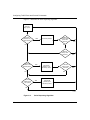
The Dequeuing Process ...........................................................................................2-3
Bandwidth Allocation Algorithm .........................................................................2-4
Strict Dequeuing Algorithm ................................................................................2-7
Configuring Protocol Prioritization ..................................................................................2-9
Configuring Protocol Prioritization on an ATM Circuit ...................................................2-10
Tuning Protocol Prioritization ........................................................................................2-10
Tuning Concepts ....................................................................................................2-10
Percent of Bandwidth .......................................................................................2-11
Queue Size ......................................................................................................2-12
Latency ............................................................................................................2-14
Editing Protocol Prioritization Parameters ..............................................................2-15
Monitoring Protocol Prioritization Statistics ............................................................2-16
Chapter 3
Inbound Traffic Filter Criteria and Actions
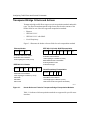
Transparent Bridge Criteria and Actions .........................................................................3-2
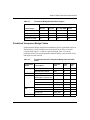
Predefined Transparent Bridge Criteria ....................................................................3-3
User-Defined Transparent Bridge Criteria ................................................................3-4
Transparent Bridge Actions ......................................................................................3-4
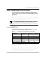
Source Route Bridging Criteria and Actions ...................................................................3-5
Predefined SRB Criteria ...........................................................................................3-5
Specifying an SRB Criterion Range ..................................................................3-5
User-Defined SRB Criteria .......................................................................................3-6
SRB Actions .............................................................................................................3-6
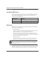
DECnet Phase IV Criteria and Actions ...........................................................................3-7
Predefined DECnet Criteria .....................................................................................3-7
User-Defined DECnet Criteria ..................................................................................3-7
DECnet Actions ........................................................................................................3-7
DLSw Criteria and Actions .............................................................................................3-8
Predefined DLSw Criteria ........................................................................................3-8
User-Defined DLSw Criteria .....................................................................................3-8
DLSw Actions ...........................................................................................................3-8
vi
308645-15.0 Rev 00
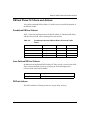
IP Criteria and Actions ....................................................................................................3-9
Predefined IP Criteria ...............................................................................................3-9
User-Defined IP Criteria ...........................................................................................3-9
IP Actions ...............................................................................................................3-10
IPX Criteria and Actions ...............................................................................................3-11
Predefined IPX Criteria ..........................................................................................3-11
User-Defined IPX Criteria ......................................................................................3-12
IPX Actions .............................................................................................................3-12
LLC2 Criteria and Actions ............................................................................................3-12
Predefined LLC2 Criteria .......................................................................................3-12
User-Defined LLC2 Criteria ....................................................................................3-13
LLC2 Actions ..........................................................................................................3-13
OSI Criteria and Actions ...............................................................................................3-13
Predefined OSI Criteria ..........................................................................................3-13
User-Defined OSI Criteria ......................................................................................3-14
OSI Actions ............................................................................................................3-14
VINES Criteria and Actions ..........................................................................................3-14
Predefined VINES Criteria .....................................................................................3-14
User-Defined VINES Criteria .................................................................................3-15
VINES Actions ........................................................................................................3-15
XNS Criteria and Actions ..............................................................................................3-15
Predefined XNS Criteria .........................................................................................3-15
User-Defined XNS Criteria .....................................................................................3-16
XNS Actions ...........................................................................................................3-16
Chapter 4
Outbound Traffic Filter Criteria and Actions
Selecting Predefined Criteria ..........................................................................................4-2
Predefined Data Link Criteria ...................................................................................4-2
Predefined IP Criteria ...............................................................................................4-5
Specifying Criteria Common to IP and Data Link Headers ......................................4-6
Selecting User-Defined Criteria ......................................................................................4-7
Data Link Reference Points ......................................................................................4-7
IP Reference Points .................................................................................................4-9
Selecting Actions ..........................................................................................................4-10
Filtering Actions .....................................................................................................4-10
308645-15.0 Rev 00
vii
Prioritizing Actions .................................................................................................4-11
Dial Service Actions ...............................................................................................4-11
Chapter 5
Specifying Common Criterion Ranges
Specifying MAC Address Ranges ...................................................................................5-2
SRB Source MAC Addresses ..................................................................................5-2
SRB Functional MAC Addresses .............................................................................5-3
Specifying VINES Address Ranges ................................................................................5-3
Specifying Source and Destination SAP Code Ranges .................................................5-4
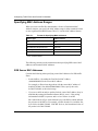
Specifying Frame Relay NLPID Ranges .........................................................................5-5
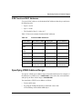
Specifying PPP Protocol ID Ranges ...............................................................................5-5
Specifying TCP and UDP Port Ranges ..........................................................................5-6
Specifying Ethernet Type Ranges ..................................................................................5-7
Specifying IP Protocol ID and Type of Service Ranges ................................................5-10
Chapter 6
Applying Inbound Traffic Filters
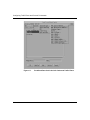
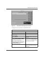
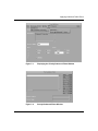
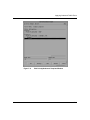
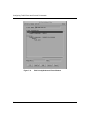
Displaying the Inbound Traffic Filters Window ................................................................6-2
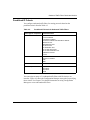
Preparing Inbound Traffic Filter Templates .....................................................................6-3
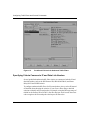
Creating a Template .................................................................................................6-4
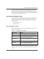
Customizing Templates ............................................................................................6-6
Copying a Template ...........................................................................................6-6
Editing a Template .............................................................................................6-7
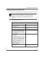
Creating an Inbound Traffic Filter ..................................................................................6-10
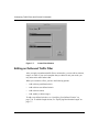
Editing an Inbound Traffic Filter ....................................................................................6-11
Enabling or Disabling an Inbound Traffic Filter .............................................................6-15
Deleting an Inbound Traffic Filter ..................................................................................6-16
Specifying User-Defined Criteria ..................................................................................6-17
Changing Inbound Traffic Filter Precedence .................................................................6-18
Chapter 7
Applying Outbound Traffic Filters
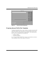
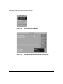
Displaying the Priority/Outbound Filters Window ...........................................................7-2
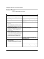
Preparing Outbound Traffic Filter Templates ..................................................................7-4
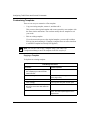
Creating a Template .................................................................................................7-4
Specifying Prioritization Length ................................................................................7-7
viii
308645-15.0 Rev 00
Customizing Templates ............................................................................................7-9
Copying a Template ...........................................................................................7-9
Editing a Template ...........................................................................................7-10
Creating an Outbound Traffic Filter ...............................................................................7-13
Editing an Outbound Traffic Filter ................................................................................7-14
Enabling or Disabling an Outbound Traffic Filter ..........................................................7-18
Deleting an Outbound Traffic Filter ...............................................................................7-19
Specifying User-Defined Criteria ..................................................................................7-20
Changing Outbound Traffic Filter Precedence ..............................................................7-21
Chapter 8
Configuring IP Inbound Traffic Filters Using the BCC
IP Inbound Traffic Filter Concepts and Terminology .......................................................8-2
IP Traffic Filter Templates .........................................................................................8-2
IP Inbound Traffic Filters ..........................................................................................8-3
Filter Precedence .....................................................................................................8-4
Filter Criteria and Actions .........................................................................................8-5
IP Filtering Actions .............................................................................................8-5
Extended and Nonextended Filtering Modes ...........................................................8-6
Creating an IP Traffic Filter Template ..............................................................................8-7
Creating an IP Inbound Traffic Filter ...............................................................................8-8
Specifying Match Criteria for IP Inbound Traffic Filters and Templates ..........................8-9
Specifying Source and Destination Networks As Match Criteria ...........................8-10
Specifying Source and Destination TCP and UDP Ports As Match Criteria ..........8-10
Specifying Protocol Identifiers As Match Criteria ...................................................8-13
Specifying the Type of Service (ToS) As Match Criteria .........................................8-15
Specifying TCP-Established Match Criteria ...........................................................8-15
Specifying User-Defined Criteria ............................................................................8-16
Specifying the Action of Inbound Traffic Filters and Templates ....................................8-16
Specifying the Log Action .......................................................................................8-19
Disabling and Reenabling IP Traffic Filters on an IP Interface ......................................8-20
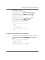
Configuration Examples ...............................................................................................8-20
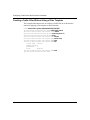
Creating an IP Traffic Filter Template .....................................................................8-20
Applying the Filter Template to an IP Traffic Filter ..................................................8-21
Creating a Traffic Filter Without Using a Filter Template ........................................8-22
308645-15.0 Rev 00
ix
Chapter 9
ATM Protocol Prioritization and Priority Queuing
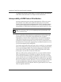
Interoperability of ATM Protocol Prioritization .................................................................9-2
Displaying the Priority/Outbound Filters Window for ATM ..............................................9-3
Configuring Protocol Priority on ATM Interfaces .............................................................9-5
Configuring Protocol Priority on ATM Service Records .................................................9-7
Overriding Protocol Priority on an ATM Interface ..........................................................9-10
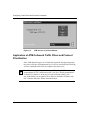
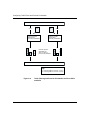
Application of ATM Outbound Traffic Filters and Protocol Prioritization ........................9-12
Direct PVCs and SVCs ..........................................................................................9-13
Grouped PVCs, Hybrid PVCs and WAN SVCs ......................................................9-15
Appendix A
Site Manager Protocol Prioritization Parameters
Priority Interface Parameter Descriptions ...................................................................... A-2
Prioritization Length Parameters ................................................................................... A-8
ATM Service Level Priority Queuing Parameter ............................................................. A-9
Appendix B
Examples and Implementation Notes
Traffic Filter Example for Basic IP Network Security ...................................................... B-1
Inbound Traffic Filter Examples ..................................................................................... B-3
Protocol Prioritization Examples .................................................................................... B-7
Creating an Outbound Traffic Filter ......................................................................... B-7
Implementation Notes .................................................................................................. B-11
Filtering Outbound Frame Relay Traffic ................................................................. B-11
Filtering over a Dial Backup Line ........................................................................... B-11
Using a Drop-All Filter As a Firewall ..................................................................... B-12
Using Outbound Traffic Filters for LAN Protocols .................................................. B-13
Index
x
308645-15.0 Rev 00
Figures
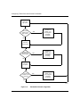
Figure 2-1.
Protocol Prioritization Dequeuing ............................................................2-4
Figure 2-2.
Bandwidth Allocation Algorithm ...............................................................2-6
Figure 2-3.
Strict Dequeuing Algorithm ......................................................................2-8
Figure 2-4.
Priority Queue Statistics for the Queue Size Example ...........................2-13
Figure 2-5.
Reconfigured Priority Queue Statistics for the Queue Size Examples ..2-14
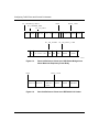
Figure 3-1.
Header Reference Fields for Transparent Bridge Encapsulation
Methods ...................................................................................................3-2
Figure 4-1.
Predefined Data Link Criteria for Outbound Traffic Filters .......................4-4
Figure 4-2.
Predefined IP Criteria for Outbound Traffic Filters ...................................4-6
Figure 4-3.
Data Link Reference Points in an SRB Packet Bridged over
Nortel Networks Proprietary Frame Relay ...............................................4-8
Figure 4-4.
Data Link Reference Points in an IEEE 802.2 LLC Header .....................4-8
Figure 4-5.
IP Reference Points in an IP-Encapsulated SRB Packet Bridged
over PPP ..................................................................................................4-9
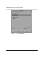
Figure 6-1.
Inbound Traffic Filters Window .................................................................6-3
Figure 6-2.
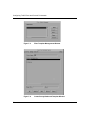
Filter Template Management Window ......................................................6-5
Figure 6-3.
Create Template Window .........................................................................6-5
Figure 6-4.
Edit Template Window .............................................................................6-8
Figure 6-5.
Create Filter Window .............................................................................6-11
Figure 6-6.
Edit Filters Window ................................................................................6-13
Figure 6-7.
Add User-Defined Field Window ............................................................6-18
Figure 6-8.
Filters Window Showing Filter Precedence ...........................................6-19
Figure 6-9.
Change Precedence Window ................................................................6-20
Figure 6-10. Filters Window Showing New Order of Precedence ..............................6-20
Figure 7-1.
Displaying the Priority/Outbound Filters Window .....................................7-3
Figure 7-2.
Priority/Outbound Filters Window ............................................................7-3
Figure 7-3.
Filter Template Management Window ......................................................7-6
Figure 7-4.
Create Priority/Outbound Template Window ............................................7-6
Figure 7-5.
Prioritization Length Window ...................................................................7-7
308645-15.0 Rev 00
xi
Figure 7-6.
Edit Priority/Outbound Template Window ..............................................7-11
Figure 7-7.
Create Filter Window .............................................................................7-14
Figure 7-8.
Edit Priority/Outbound Filters Window ...................................................7-16
Figure 7-9.
Add User-Defined Field Window ............................................................7-21
Figure 7-10. Priority/Outbound Filters Window Showing Filter Precedence ..............7-22
Figure 7-11. Change Precedence Window ................................................................7-23
Figure 7-12. Priority/Outbound Filters Window Showing New Order of Precedence ..7-23
xii
Figure 9-1.
Priority/Outbound Filters Window ............................................................9-4
Figure 9-2.
ATM Priority Interface List Window ..........................................................9-7
Figure 9-3.
ATM Service Records List ........................................................................9-9
Figure 9-4.
Edit Protocol Priority Interface Window ..................................................9-10
Figure 9-5.
ATM Service Level Filter Window ...........................................................9-12
Figure 9-6.
Traffic Filtering and Protocol Prioritization for Direct PVCs and SVCs ...9-14
Figure 9-7.
Traffic Filtering and Protocol Prioritization for Grouped PVCs, Hybrid
PVCs, and WAN SVCs ..........................................................................9-15
308645-15.0 Rev 00
Tables
Table 1-1.
Predefined Inbound Traffic Filter Criteria .................................................1-8
Table 1-2.
Predefined Outbound Traffic Filter Criteria ...............................................1-9
Table 1-3.
Inbound Traffic Filter Actions ..................................................................1-12
Table 1-4.
Outbound Traffic Filter Actions ...............................................................1-12
Table 1-5.
Summary of Traffic Filter Support ..........................................................1-14
Table 3-1.
Transparent Bridge Encapsulation Support .............................................3-3
Table 3-2.
Predefined Criteria for Transparent Bridge Inbound Traffic Filters ...........3-3
Table 3-3.
Predefined Criteria for SRB Inbound Traffic Filters ..................................3-5
Table 3-4.
Predefined Criteria for DECnet Phase IV Inbound Traffic Filters .............3-7
Table 3-5.
Predefined Criteria for DLSw Inbound Traffic Filters ................................3-8
Table 3-6.
Predefined Criteria for IP Inbound Traffic Filters ......................................3-9
Table 3-7.
User-Defined Criteria for IP Inbound Traffic Filters ................................3-10
Table 3-8.
Predefined Criteria for IPX Inbound Traffic Filters ..................................3-11
Table 3-9.
Predefined Criteria for LLC2 Inbound Traffic Filters ...............................3-12
Table 3-10.
Predefined Criteria for OSI Inbound Traffic Filters .................................3-13
Table 3-11.
Predefined Criteria for VINES Inbound Traffic Filters .............................3-14
Table 3-12.
Predefined Criteria for XNS Inbound Traffic Filters ................................3-15
Table 4-1.
Predefined Data Link Criteria for Outbound Traffic Filters .......................4-2
Table 4-2.
Predefined IP Criteria for Outbound Traffic Filters ...................................4-5
Table 4-3.
Data Link Reference Points .....................................................................4-7
Table 4-4.
IP Reference Points ................................................................................4-9
Table 5-1.
Format for Specifying MAC Addresses ....................................................5-2
Table 5-2.
Functional MAC Addresses .....................................................................5-3
Table 5-3.
SAP Codes ..............................................................................................5-4
Table 5-4.
Frame Relay NLPIDs ...............................................................................5-5
Table 5-5.
PPP Protocol IDs .....................................................................................5-5
Table 5-6.
Source and Destination TCP Ports ..........................................................5-6
Table 5-7.
Source and Destination UDP Ports ..........................................................5-6
Table 5-8.
Ethernet Type Codes ...............................................................................5-7
308645-15.0 Rev 00
xiii
Table 5-9.
xiv
IP Protocol ID Codes .............................................................................5-10
Table 5-10.
IP Type of Service Codes .......................................................................5-10
Table 6-1.
Using the Edit Template Window .............................................................6-9
Table 6-2.
Using the Edit Filters Window ................................................................6-14
Table 7-1.
Using the Edit Priority/Outbound Template Window ..............................7-12
Table 7-2.
Using the Edit Priority/Outbound Filters Window ...................................7-17
Table 8-1.
TCP and UDP Match Criteria Parameters .............................................8-11
Table 8-2.
Common TCP Ports ...............................................................................8-12
Table 8-3.
Common UDP Ports ..............................................................................8-12
Table 8-4.
Common Protocol IDs for IP Traffic ........................................................8-14
Table 8-5.
Actions and Dependencies for Inbound IP Traffic Filters .......................8-17
Table B-1.
Predefined Criteria, Ranges, and Actions for Sample Inbound
Traffic Filters ............................................................................................ B-5
Table B-2.
User-Defined Criteria and Ranges for Sample Inbound Traffic Filters .... B-6
Table B-3.
Sample Criteria, Ranges, and Actions for Protocol Prioritization ............ B-9
308645-15.0 Rev 00
Preface
This guide describes how to configure traffic filters and prioritize traffic on a
Nortel Networks* router.
You can use Site Manager to configure traffic filters on a router. You can use the
Bay Command Console (BCC*) to configure IP inbound traffic filters on a router.
Before You Begin
Before using this guide, you must complete the following procedures. For a new
router:
•
Install the router (see the installation guide that came with your router).
•
Connect the router to the network and create a pilot configuration file (see
Quick-Starting Routers, Configuring BayStack Remote Access, or Connecting
ASN Routers to a Network).
Make sure that you are running the latest version of Nortel Networks BayRS* and
Site Manager software. For information about upgrading BayRS and Site
Manager, see the upgrading guide for your version of BayRS.
308645-15.0 Rev 00
xv
Configuring Traffic Filters and Protocol Prioritization
Text Conventions
This guide uses the following text conventions:
angle brackets (< >)
Indicate that you choose the text to enter based on the
description inside the brackets. Do not type the
brackets when entering the command.
Example: If the command syntax is:
ping <ip_address>, you enter:
ping 192.32.10.12
bold text
Indicates command names and options and text that
you need to enter.
Example: Enter show ip {alerts | routes}.
Example: Use the dinfo command.
braces ({})
Indicate required elements in syntax descriptions
where there is more than one option. You must choose
only one of the options. Do not type the braces when
entering the command.
Example: If the command syntax is:
show ip {alerts | routes}, you must enter either:
show ip alerts or show ip routes, but not both.
brackets ([ ])
Indicate optional elements in syntax descriptions. Do
not type the brackets when entering the command.
Example: If the command syntax is:
show ip interfaces [-alerts], you can enter either:
show ip interfaces or show ip interfaces -alerts.
ellipsis points (. . . )
Indicate that you repeat the last element of the
command as needed.
Example: If the command syntax is:
ethernet/2/1 [<parameter> <value>] . . . , you enter
ethernet/2/1 and as many parameter-value pairs as
needed.
xvi
308645-15.0 Rev 00
Preface
italic text
Indicates new terms, book titles, and variables in
command syntax descriptions. Where a variable is two
or more words, the words are connected by an
underscore.
Example: If the command syntax is:
show at <valid_route>
valid_route is one variable and you substitute one value
for it.
screen text
Indicates system output, for example, prompts and
system messages.
Example: Set Trap Monitor Filters
separator ( > )
Shows menu paths.
Example: Protocols > IP identifies the IP option on the
Protocols menu.
vertical line ( | )
Separates choices for command keywords and
arguments. Enter only one of the choices. Do not type
the vertical line when entering the command.
Example: If the command syntax is:
show ip {alerts | routes}, you enter either:
show ip alerts or show ip routes, but not both.
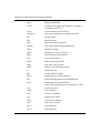
Acronyms
AAL
ATM adaptation layer
ANSI
American National Standards Institute
APPN
Advanced Peer-to-Peer Networking
ARP
Address Resolution Protocol
ATM
Asynchronous Transfer Mode
BCC*
Bay Command Console
BCN*
Backbone Concentrator Node
308645-15.0 Rev 00
xvii
Configuring Traffic Filters and Protocol Prioritization
xviii
BLN*
Backbone Link Node
CCITT
International Telegraph and Telephone Consultative
Committee (now ITU-T)
CLNP
Connectionless Network Protocol
CSMA/CD
carrier sense multiple access/collision detection
DE
discard eligible
DLC
data link control
DLCI
data link connection identifier
DLCMI
Data Link Control Management Interface
DLSw
data link switching
DSAP
destination service access point
FDDI
Fiber Distributed Data Interface
FTP
File Transfer Protocol
HDLC
high-level data link control
HSSI
high-speed serial interface
ICMP
Internet Control Message Protocol
IP
Internet Protocol
IPX
Internet Packet Exchange
ISDN
Integrated Services Digital Network
ISO
International Organization for Standardization
ITU-T
International Telecommunications
Union–Telecommunications sector (formerly CCITT)
LAN
local area network
LANE
LAN emulation
LAT
Local Area Transport
LLC
Logical Link Control
LNM
LAN Network Manager
MAC
media access control
MCE1
multichannel E1
MCT1
multichannel T1
308645-15.0 Rev 00
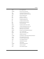
Preface
MSB
most significant bit
NLPID
network layer protocol ID
OSI
Open Systems Interconnection
OSPF
Open Shortest Path First (protocol)
PPP
Point-to-Point Protocol
PRI
primary rate interface
PVC
permanent virtual circuit
RIF
routing information field
RII
routing information indicator
RIP
Routing Information Protocol
SAP
service access point
SDLC
Synchronous Data Link Control
SMDS
switched multimegabit data service
SNA
Systems Network Architecture
SNAP
Subnetwork Access Protocol
SNMP
Simple Network Management Protocol
SRB
source routing bridge
SSAP
source service access point
STP
shielded twisted pair
TCP/IP
Transmission Control Protocol/Internet Protocol
Telnet
Telecommunication network
TFTP
Trivial File Transfer Protocol
UDP
User Datagram Protocol
UTP
unshielded twisted pair
VC
virtual circuit
VINES
Virtual Network Systems
WAN
wide area network
XNS
Xerox Network System
308645-15.0 Rev 00
xix
Configuring Traffic Filters and Protocol Prioritization
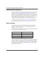
Hard-Copy Technical Manuals
You can print selected technical manuals and release notes free, directly from the
Internet. Go to the www.nortelnetworks.com/documentation URL. Find the
product for which you need documentation. Then locate the specific category and
model or version for your hardware or software product. Use Adobe* Acrobat
Reader* to open the manuals and release notes, search for the sections you need,
and print them on most standard printers. Go to Adobe Systems at the
www.adobe.com URL to download a free copy of the Adobe Acrobat Reader.
You can purchase selected documentation sets, CDs, and technical publications
through the Internet at the www1.fatbrain.com/documentation/nortel/ URL.
How to Get Help
If you purchased a service contract for your Nortel Networks product from a
distributor or authorized reseller, contact the technical support staff for that
distributor or reseller for assistance.
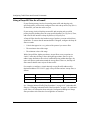
If you purchased a Nortel Networks service program, contact one of the following
Nortel Networks Technical Solutions Centers:
Technical Solutions Center
Telephone
Europe, Middle East, and Africa
(33) (4) 92-966-968
North America
(800) 4NORTEL or (800) 466-7835
Asia Pacific
(61) (2) 9927-8800
China
(800) 810-5000
An Express Routing Code (ERC) is available for many Nortel Networks products
and services. When you use an ERC, your call is routed to a technical support
person who specializes in supporting that product or service. To locate an ERC for
your product or service, go to the www12.nortelnetworks.com/ URL and click
ERC at the bottom of the page.
xx
308645-15.0 Rev 00
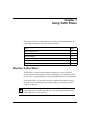
Chapter 1
Using Traffic Filters
This chapter describes concepts and terms to help you understand and plan for
traffic filter configurations on Nortel Networks routers.
Topic
Page
What Are Traffic Filters?
1-1
What Is Protocol Prioritization?
1-3
Filtering Strategies
1-4
Traffic Filter Components
1-6
Using Filter Templates
1-13
Summary of Traffic Filter Support
1-14
What Are Traffic Filters?
Traffic filters are router files that instruct an interface to selectively handle
specified network traffic (packets, frames, or datagrams). You determine which
packets receive special handling based on information fields in the packet headers.
Using traffic filters, you can reduce network congestion and control access to
network resources by blocking, forwarding, logging, or prioritizing specified
traffic on an interface.
Note: Do not confuse traffic filters with other router filters. Traffic filters help
you manage customer traffic. Routing filters help you manage routing control
traffic (such as route table updates).
308645-15.0 Rev 00
1-1
Configuring Traffic Filters and Protocol Prioritization
Nortel Networks routers support two types of traffic filters:
•
Inbound traffic filters act on packets that the router is receiving.
•
Outbound traffic filters act on packets that the router is forwarding.
You can create traffic filters on the following router interfaces:
•
•
•
•
•
•
•
Ethernet (10BASE-T and 100BASE-T)
FDDI
HSSI
MCE1
MCT1
Synchronous
Token ring
You can apply multiple traffic filters to a single interface. When more than one
filter applies to a packet, the order of filters determines the filtering result.
Inbound Traffic Filters
Inbound traffic filters act on packets arriving at a particular router interface. Most
sites use inbound traffic filters primarily for security, to restrict access to nodes in
a network.
When you configure inbound traffic filters, you specify a set of conditions that
apply to the traffic of a particular bridging or routing protocol. The Configuration
Manager supports inbound traffic filters for the following protocols:
•
•
•
•
•
•
•
•
•
•
1-2
Transparent bridge (four encapsulation methods: Ethernet, 802.2 LLC, 802.2
LLC with SNAP, and Novell Proprietary)
Native source route bridging (SRB)
IP
IPX
XNS
OSI
DECnet Phase IV
VINES
DLSw
LLC2 (APPN and LNM)
308645-15.0 Rev 00
Using Traffic Filters
Chapter 3 provides protocol-specific information for designing inbound traffic
filters. Chapter 6 explains how to use the Configuration Manager to apply inbound
traffic filters.
Outbound Traffic Filters
Outbound traffic filters act on packets that the router forwards to a local area
network (LAN) or wide area network (WAN) through a particular interface. Most
sites use outbound traffic filters to ensure timely delivery of critical data, or to
restrict traffic leaving the local network.
Outbound traffic filters are not based on a routing protocol, as are inbound traffic
filters. When you configure outbound traffic filters, you specify a set of conditions
that apply to the following packet headers:
•
•
Data link control (DLC) header
IP header
To use outbound traffic filters, you must select Protocol Priority as one of the
configured protocols on an interface. Protocol Priority is enabled by default on
circuits configured with Frame Relay or PPP. Otherwise, you must enable
Protocol Priority the first time you configure outbound traffic filters on an
interface.
Chapter 4 provides information for designing outbound traffic filters. Chapter 7
explains how to use the Configuration Manager to enable Protocol Priority and
apply outbound traffic filters.
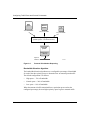
What Is Protocol Prioritization?
Protocol prioritization is an outbound traffic filter mechanism.
With Protocol Priority enabled on an interface, the router sorts traffic into
prioritized delivery queues (High, Normal, and Low), called priority queues.
Priority queues affect the sequence in which data leaves an interface; they do not
affect traffic as it arrives at the router. You use outbound traffic filters to specify
how traffic is sorted into priority queues. By default, all outbound traffic goes to
the Normal queue.
See Chapter 2 to learn more about priority queuing and dequeuing.
308645-15.0 Rev 00
1-3
Configuring Traffic Filters and Protocol Prioritization
Filtering Strategies
This section recommends ways you might use traffic filters in a network. See
Appendix B for specific examples.
Direct Traffic
You can create traffic filters that affect a particular protocol’s traffic. For example,
you can forward all IP traffic to a next-hop address. You can also create traffic
filters that affect certain locations on a bridged network. For example, if you want
all traffic from a node with a particular source MAC address (perhaps an
application server) to take precedence over other traffic, you can use protocol
prioritization to assign a high priority to any traffic with that source address.
Drop or Accept Traffic
You can configure a router interface to accept only specified traffic and drop all
other packets by configuring inbound traffic filters with specific accept criteria.
Or, to accept most traffic and drop only specified packets, you can configure
inbound traffic filters for the traffic you want to drop.
Note: Drop filters are generally more efficient than Accept filters.
For example, to prevent all NetBIOS traffic from entering a particular LAN
segment, you can create an inbound traffic filter to drop all packets with a
destination or source SAP code of F0.
Prioritize Traffic
You can use protocol prioritization to expedite traffic coming from a particular
source or going to a particular destination.
When a router treats all packets equally, there is no way to ensure consistent
network services for users who are working with real-time applications. Bulk
transfer applications use too much of the available bandwidth and reduce
interactive response time. These problems are especially noticeable on low-speed
WAN interfaces.
1-4
308645-15.0 Rev 00
Using Traffic Filters
You can also improve application response time and prevent session timeouts by
implementing protocol prioritization.
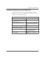
Combine Filters
On most interfaces, you can apply as many as 31 inbound and 31 outbound traffic
filters for each protocol. You can configure IP interfaces to support as many as 127
inbound traffic filters.
As you add filters to an interface, the Configuration Manager numbers them
chronologically (Filter No. 1, Filter No. 2, Filter No. 3, and so on). The filter rule
number determines the filter’s precedence. Lower numbers have higher
precedence; Filter No. 1 has the highest precedence. If a packet matches two
filters, the filter with the highest precedence (lowest number) applies.
After you create traffic filters, you can change their precedence by reordering
them. See “Changing Inbound Traffic Filter Precedence” on page 6-18 (inbound
traffic filters) or “Changing Outbound Traffic Filter Precedence” on page 7-21
(outbound traffic filters).
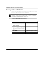
Build a Firewall
If your filtering strategy involves blocking most or all inbound traffic (a firewall)
you can create a Drop-all filter for each protocol on the interface. That means for
each protocol you are filtering, you choose a filter criterion that appears in every
packet of the protocol (for example, a MAC address).
You can also create exceptions to the Drop-all filter by adding more-specific,
higher-precedence filters to allow only specified traffic on an interface. See
“Using a Drop-All Filter As a Firewall” on page B-12 for more information about
combining filters to accept certain traffic.
308645-15.0 Rev 00
1-5
Configuring Traffic Filters and Protocol Prioritization
Traffic Filter Components
The Configuration Manager creates traffic filters from template files that contain
filtering information. Traffic filter templates consist of three components:
•
Criteria
The portion of the incoming packet, frame, or datagram header to be
examined
•
Ranges
Numeric values (often addresses) to be compared with the contents of
examined packets
•
Actions
What happens to packets that match the criteria and ranges specified in a filter
To create a traffic filter, you apply a filter template to a particular router interface.
Table 1-5 (at the end of this chapter) summarizes the inbound and outbound traffic
filter criteria and actions supported on specific interfaces.
Criteria
A filter criterion is the portion of a packet, frame, or datagram header to be
examined. You can break down any packet into at least three components:
•
The DLC (or data link) header. Examples of data link header types include:
-- Token ring (802.5)
-- Ethernet V.2 and IEEE 802.3
-- FDDI
-- PPP and Nortel Networks Standard
-- Frame Relay
•
The upper-level protocol header. Examples of protocol header types include:
-- IP and TCP
-- Source route bridging (SRB)
-- DLSw
•
1-6
User data
308645-15.0 Rev 00
Using Traffic Filters
A traffic filter criterion is defined by a byte length and an offset from common bit
patterns (reference points) in the data link or protocol header. The criterion
includes the length of the filtered pattern and an offset from the known reference
point. The traffic filter uses this information to locate which portion of a packet to
examine.
For bridged traffic, predefined criteria are part of the data link header. For routed
traffic, a predefined criterion can be part of the data link header or an upper-level
protocol header.
Inbound traffic filter criteria use reference points in the upper-level protocol
header. You select inbound criteria based on the protocol of the incoming traffic.
Outbound traffic filters use reference points in only the IP or DLSw protocol
headers. You select outbound criteria based on the WAN protocol configured on
the interface (transparent bridge, SRB, PPP, or Frame Relay).
Predefined and User-Defined Criteria
The Configuration Manager provides a selection of default filter criteria
(predefined criteria) for both inbound and outbound traffic filters. Predefined
criteria consist of predefined offsets and lengths from common reference points.
You can also define a criterion based on bit patterns in a packet header that are not
supported in predefined criteria (user-defined criteria). To apply user-defined
criteria, you specify the bit length and offset from a supported reference point.
Chapter 3 lists the supported reference points for inbound traffic filters. lists the
reference points for outbound traffic filters.
To fit your site’s traffic patterns, you can use a combination of predefined and
user-defined criteria in up to 32 traffic filters on each interface.
308645-15.0 Rev 00
1-7
Configuring Traffic Filters and Protocol Prioritization
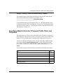
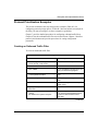
Predefined Criteria
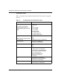
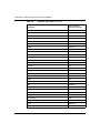
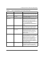
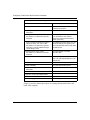
Table 1-1 summarizes the predefined inbound traffic filter criteria for supported
protocols.
Table 1-1.
Predefined Inbound Traffic Filter Criteria
Traffic Type
Predefined Inbound Filter Criteria
Transparent bridge
MAC Address (Source or Destination)
Ethernet Type
Novell
802.2 LLC Length
802.2 LLC DSAP
802.2 LLC SSAP
802.2 LLC Control
802.2 SNAP Length
802.2 SNAP Protocol ID
802.2 SNAP Ethernet Type
(Four data link encapsulation
methods: Ethernet, 802.2 LLC,
Novell Proprietary, 802.2 LLC with
SNAP)
SRB
(Native only; IP-encapsulated SRB
is not supported)
MAC Address (Source or Destination)
DSAP
SSAP
NetBIOS Name (Source or Destination)
DECnet Phase IV
Area (Source or Destination)
Node (Source or Destination)
DLSw
MAC Address (Source or Destination)
DSAP
SSAP
IP
Type of Service
IP Address (Source or Destination)
UDP Port (Source and/or Destination)
TCP Port (Source and/or Destination)
UDP or TCP Source Port
UDP or TCP Destination Port
Established TCP Protocols
Protocol Type
IPX
Network (Source or Destination)
Host Address (Source or Destination)
Socket (Source or Destination)
OSI
OSI Area (Source or Destination)
System ID (Source or Destination)
(continued)
1-8
308645-15.0 Rev 00
Using Traffic Filters
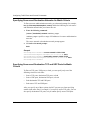
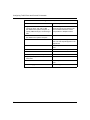
Table 1-1.
Predefined Inbound Traffic Filter Criteria (continued)
Traffic Type
Predefined Inbound Filter Criteria
LLC2
MAC Address (Source or Destination)
DSAP
SSAP
VINES
Protocol Type
VINES Address (Source or Destination)
XNS
Network (Source or Destination)
Address (Source or Destination)
Socket (Source or Destination)
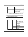
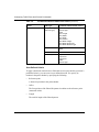
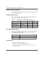
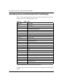
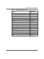
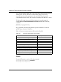
Table 1-2 summarizes the predefined outbound traffic filter criteria for data link
and IP headers.
Note: See Configuring DLSw Services for information about criteria for
outbound traffic filters based on the DLSw header.
Table 1-2.
Predefined Outbound Traffic Filter Criteria
Header
Traffic Type
Predefined Outbound Filter Criteria
IP header
IP
Type of Service
Priority_IP Address (Source and/or
Destination)
UDP Port (Source and/or Destination)
TCP Port (Source and/or Destination)
Established TCP
Protocol Type
Native SRB
SSAP
Destination Address
Source Address
PPP
Protocol ID
Frame Relay
2-byte DLCI
3-byte DLCI
4-byte DLCI
NLPID
(continued)
308645-15.0 Rev 00
1-9
Configuring Traffic Filters and Protocol Prioritization
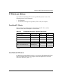
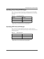
Table 1-2.
Predefined Outbound Traffic Filter Criteria (continued)
Header
Traffic Type
Predefined Outbound Filter Criteria
Data link header
Transparent bridge
(Data Link Type)
MAC Address (Source or Destination)
Ethernet Type
Novell
802.2 Length
802.2 DSAP
802.2 SSAP
802.2 Control
802.2 SNAP Length
802.2 SNAP Protocol ID
802.2 SNAP Ethernet Type
Native SRB
SSAP
DSAP
PPP
Protocol ID
Frame Relay
2-byte DLCI
3-byte DLCI
4-byte DLCI
NLPID
Ethernet Type
User-Defined Criteria
To apply customized criteria that use fields that are not represented in a protocol’s
predefined criteria, you can create a user-defined criterion. You specify its
location in the packet header by specifying the following:
•
Reference point
A known bit position in the packet header
•
Offset
The first position of the filtered bit pattern in relation to the reference point
(measured in bits)
•
Length
The total bit length of the filtered pattern
1-10
308645-15.0 Rev 00
Using Traffic Filters
Ranges
For each traffic filter criterion, you also specify the valid range, a series of target
values that apply to the criterion. For most criteria, you specify an address range.
There must be at least one target value for each criterion. The range can be just
one value or a set of values.
You enter a minimum and a maximum value to specify the range. For a range of
only one value, you enter only the minimum value; the Configuration Manager
automatically uses that value for both the minimum and maximum value.
For example, if the filter criteria is MAC Source Address, you must specify which
addresses you want the filter to examine. If you specify 0x0000A2000001 as the
minimum range value and 0x0000A2000003 as the maximum range value, the
router checks for packets with a MAC source address between 0x0000A2000001
and 0x0000A2000003, inclusive.
Note: Chapter 5 lists valid ranges for common traffic filter criteria and
explains how to specify some common address ranges.
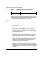
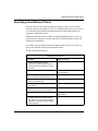
Actions
The filter action determines what happens to packets that match a filter criterion’s
ranges. You can apply the following actions to any traffic filter:
•
Accept
The router processes any packet that matches the filter criteria and ranges.
•
Drop
The router does not route any packet that matches the filter criteria and ranges.
•
Log
For every packet that matches the filter criteria and ranges, the router sends an
entry to the system Events log. You can specify the Log action in combination
with other actions.
308645-15.0 Rev 00
1-11
Configuring Traffic Filters and Protocol Prioritization
Note: Specify the Log action only to record abnormal events; otherwise, the
Events log will fill up with filtering messages, leaving no room for critical log
messages.
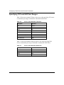
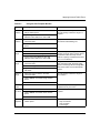
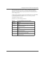
Table 1-3 lists additional protocol-specific actions for inbound traffic filters. See
Chapter 3 for more information.
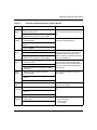
Table 1-3.
Inbound Traffic Filter Actions
Protocol
Inbound Traffic Filters
All protocols
Drop
Accept
Log
Transparent bridge
Flood
Forward to Circuit List
Native SRB
Direct IP Explorers
Forward to Circuits
DLSw
Forward to Peer
IP
Forward to Next Hop
Drop If Next Hop Is Unreachable
Forward to IP Address
Forward to Next Hop Interface
Forward to First Up Next Hop Interface
Detailed Logging
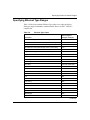
Table 1-4 lists the actions for outbound traffic filters. See Chapter 4 for more
information.
Table 1-4.
Outbound Traffic Filter Actions
Filtering Actions
Prioritizing Actions*
Dial Service Actions
Drop
High Queue
No Call
Accept
Low Queue
No Reset
Log
Length
Detailed Log
* Outbound traffic filters with a prioritizing action are sometimes called priority filters.
1-12
308645-15.0 Rev 00
Using Traffic Filters
Except for the log actions, inbound and outbound traffic filter actions are mutually
exclusive; you can only apply one action to each filter.
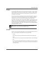
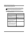
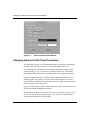
Using Filter Templates
When you create traffic filters, it is important to understand the difference
between a traffic filter template and an actual traffic filter.
A traffic filter template is a reusable, predefined specification for a traffic filter.
Each template contains a complete filter specification (criterion, range, and
action) for one protocol, but is not associated with a specific interface or circuit.
You create an actual traffic filter when you use the Configuration Manager to
apply (save) a traffic filter template to a configured router interface. You can apply
a single template to as many interfaces as you want, thus creating multiple filters
for that protocol.
When you want to add a filter to an interface, you have several options:
•
If there is a template that contains the exact filtering instructions you want for
this interface, apply that template to the interface.
•
If there is a template that contains filtering instructions similar to what you
want, copy, rename, and edit the template. Then, apply the new template to the
appropriate interface.
•
If there is no template containing filtering instructions similar to what you
want for this interface, you must create a template from scratch. Then, apply
the new template to the appropriate interface.
•
If there is an existing filter on the interface that contains instructions similar to
what you want, edit the existing filter and save it.
308645-15.0 Rev 00
1-13
Configuring Traffic Filters and Protocol Prioritization
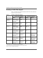
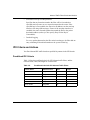
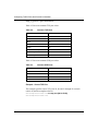
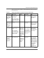
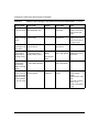
Summary of Traffic Filter Support
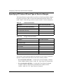
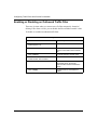
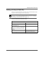
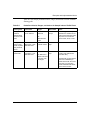
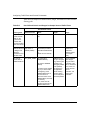
Table 1-5 summarizes the inbound and outbound traffic filter criteria and actions
supported on specific interfaces.
Table 1-5.
Summary of Traffic Filter Support
Protocol Criteria Supported
Filter Actions Supported
Network Interface
Inbound
Outbound
Inbound
Outbound
Ethernet
(10BASE-T or
100BASE-T)
Transparent bridge*,
DECnet IV, DLSw, IP,
IPX, LLC2, OSI, SRB,
XNS, VINES
Transparent bridge,
IP, SRB
Accept, Drop,
Log †
Accept, Drop, Log
FDDI
Transparent bridge‡,
DECnet IV, DLSw, IP,
IPX, LLC2, OSI, SRB,
XNS, VINES
Transparent bridge,
IP, SRB
Accept, Drop,
Log †
Accept, Drop, Log
Token ring
Transparent bridge‡,
DECnet IV, DLSw, IP,
IPX, LLC2, OSI, SRB,
XNS, VINES
Transparent bridge,
IP, SRB
Accept, Drop,
Log †
Accept, Drop, Log
HSSI
Transparent bridge*,
DECnet IV, DLSw, IP,
IPX, LLC2, OSI, SRB,
XNS, VINES
Transparent bridge,
Frame Relay, IP,
PPP, SRB
Accept, Drop,
Log †
Accept, Drop, Log
MCE1
Transparent bridge,
DECnet IV, DLSw, IP,
IPX, LLC2, OSI, SRB,
XNS, VINES
Transparent bridge,
Frame Relay, IP,
PPP, SRB
None
Accept, Drop, Log,
High Queue, Low
Queue, Length, No
Call, No Reset
MCT1
Transparent bridge,
DECnet IV, DLSw, IP,
IPX, LLC2, OSI, SRB,
XNS, VINES
Transparent bridge,
Frame Relay, IP,
PPP, SRB
None
Accept, Drop, Log,
High Queue, Low
Queue, Length, No
Call, No Reset
Synchronous
Transparent bridge*,
DECnet IV, DLSw, IP,
IPX, LLC2, OSI, SRB,
XNS, VINES
Transparent bridge,
Frame Relay, IP,
PPP, SRB
Accept, Drop,
Log †
Accept, Drop, Log,
High Queue, Low
Queue, Length, No
Call, No Reset
* Ethernet, 802.2 LLC, LLC with SNAP, and Novell encapsulations.
† Plus additional actions for transparent bridge, SRB, and IP filters (see Chapter 3).
‡ 802.2 LLC and LLC with SNAP encapsulations.
1-14
308645-15.0 Rev 00
Chapter 2
Using Protocol Prioritization Queues
This chapter describes the priority queues that you can implement using outbound
traffic filters (protocol prioritization).
Topic
Page
About Protocol Prioritization
2-1
Configuring Protocol Prioritization
2-9
Configuring Protocol Prioritization on an ATM Circuit
2-10
Tuning Protocol Prioritization
2-10
For instructions on using the Configuration Manager to create outbound traffic
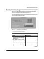
filters, see Chapter 7.
About Protocol Prioritization
Site Manager supports protocol prioritization on synchronous (serial), HSSI,
MCE1, and MCT1 interfaces for the following WAN protocols:
•
PPP
•
Nortel Networks Standard PPP
•
Frame relay
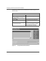
Site Manager also supports protocol prioritization for ATM services. For
information about configuring protocol prioritization for ATM services, see
Chapter 9.
308645-15.0 Rev 00
2-1
Configuring Traffic Filters and Protocol Prioritization
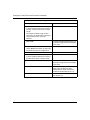
Note: The DLSw software also allows you to prioritize traffic within DLSw,
based on predefined or user-defined fields at the TCP level. For information
about these DLSw prioritization filters, see Configuring DLSw Services.
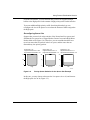
While the router is operating, network traffic from various sources converges at
each WAN interface. Without protocol prioritization, the router transmits packets
in a first in, first out (FIFO) order.
With Protocol Priority enabled on an interface, the router sorts traffic into
prioritized delivery queues (High, Normal, and Low), called priority queues. The
router uses a dequeuing algorithm to empty the priority queues to transmit traffic.
Generally, the router transmits higher-priority traffic first. Other configurable
values in the protocol prioritization scheme also affect the transmission of traffic.
Two of these values are the maximum size of the queue (queue depth) and the line
delay (latency), described in “Tuning Protocol Prioritization” on page 2-10.
Protocol prioritization is considered an outbound filter mechanism for these
reasons:
•
You use outbound traffic filters to specify how traffic is prioritized.
•
Priority queues affect the sequence in which data leaves an interface; they do
not affect traffic as it arrives at the router.
Outbound traffic filters include prioritizing actions for specifying priority queues.
See “Prioritizing Actions” on page 4-11.
The following sections describe how the router prioritizes traffic into queues, and
the options for dequeuing:
2-2
•
Priority Queuing
•
The Dequeuing Process
308645-15.0 Rev 00
Using Protocol Prioritization Queues
Priority Queuing
With protocol prioritization enabled on an interface, the router sends each packet
leaving an interface to one of three priority queues:
•
High queue
•
Normal queue
•
Low queue
The router automatically queues packets that do not match a priority filter to the
Normal queue. To send traffic to the other queues, you create outbound traffic
filters that include a prioritizing action. These are called priority filters.
The Dequeuing Process
After queuing packets, the router empties the priority queues by sending the traffic
to the transmit queue using one of two dequeuing algorithms:
•
Bandwidth Allocation Algorithm
•
Strict Dequeuing Algorithm
By default, protocol prioritization uses the bandwidth allocation algorithm to send
traffic from the three priority queues to the transmit queue. You specify the active
dequeuing algorithm by setting the Prioritization Algorithm Type parameter, as
described in “Editing Protocol Prioritization Parameters” on page 2-15.
Figure 2-1 illustrates the dequeuing process, with default configuration values.
308645-15.0 Rev 00
2-3
Configuring Traffic Filters and Protocol Prioritization
High
queue
Normal
queue
70% of bandwidth
20% of bandwidth
Low
queue
10% of bandwidth
Dequeuing algorithm
(Default algorithm = bandwidth allocation)
Transmit
queue
(Default latency
= 250 ms)
Physical
interface
Figure 2-1.
TF0001A
Protocol Prioritization Dequeuing
Bandwidth Allocation Algorithm
The bandwidth allocation algorithm uses a configurable percentage of bandwidth
for each of the three priority queues to determine how to transmit queued traffic.
The default configuration is as follows:
•
High queue -- 70% of bandwidth
•
Normal queue -- 20% of bandwidth
•
Low queue -- 10% of bandwidth
When the amount of traffic transmitted from a particular queue reaches the
configured percentage, the next-higher-priority queue begins to transmit traffic.
2-4
308645-15.0 Rev 00
Using Protocol Prioritization Queues
The amount of actual data transmitted depends on the clock speed of the circuit.
You can configure the clock speed on a synchronous interface by setting the
External Clock Speed parameter in the Configuration Manager Edit Sync
Parameters window. (See Configuring WAN Line Services.)
The bandwidth allocation algorithm works as follows:
1.
The transmit queue scans the High queue.
If there is no traffic in the High queue, the algorithm proceeds to step 3.
2.
The router empties all packets from the High queue, up to the configured
bandwidth percentage, into the transmit queue and then transmits the packets.
The default bandwidth percentage for the High queue is 70 percent. If the
actual bandwidth use is less than the limit, the router empties the High queue
and proceeds to the Normal queue.
3.
The transmit queue scans the Normal queue.
If there is no traffic in the Normal queue, the algorithm proceeds to step 5.
4.
The router empties all packets from the Normal queue, up to the configured
bandwidth percentage, into the transmit queue and then transmits the packets.
The default bandwidth percentage for the Normal queue is 20 percent. If the
actual bandwidth use is less than the limit, the router empties the Normal
queue and proceeds to the Low queue.
5.
The transmit queue scans the Low queue.
If there is no traffic in the Low queue, the algorithm returns to step 1.
6.
The router empties all packets from the Low queue, up to the configured
bandwidth percentage, into the transmit queue and then transmits the packets.
The default bandwidth percentage for the Low queue is 10 percent. If the
actual bandwidth use is less than the limit, the router empties the Low queue.
7.
The algorithm returns to step 1.
Figure 2-2 illustrates the bandwidth allocation algorithm.
308645-15.0 Rev 00
2-5
Configuring Traffic Filters and Protocol Prioritization
Scan the
High queue.
Are there
packets in the
High queue?
YES
Transmit all
packets, up to
the configured
bandwidth
percentage.
NO
Scan the
Normal queue.
Are there
packets in the
Normal queue?
YES
Transmit all
packets, up to
the configured
bandwidth
percentage.
NO
Scan the
Low queue.
Are there
packets in the
Low queue?
YES
Transmit all
packets, up to
the configured
bandwidth
percentage.
NO
TF0002A
Figure 2-2.
2-6
Bandwidth Allocation Algorithm
308645-15.0 Rev 00
Using Protocol Prioritization Queues
Strict Dequeuing Algorithm
Instead of the bandwidth allocation algorithm, you can configure the router to use
the strict dequeuing algorithm to send traffic to the transmit queue.
Caution: If the router uses the strict dequeuing algorithm and there is a great
deal of High queue traffic on the network, Normal and Low queue traffic may
never be transmitted.
The strict dequeuing algorithm works as follows:
1.
The transmit queue scans the High queue.
If there is no traffic in the High queue, the algorithm proceeds to step 4.
2.
The router empties all packets from the High queue into the transmit queue,
up to the latency value or the maximum transmit queue size, and then
transmits the packets.
The transmit queue size is the maximum number of packets in the transmit
queue at one time. You cannot configure this number using Site Manager.
3.
If the latency value is reached, the transmit queue returns to step 1, scanning
and emptying traffic from the High queue.
If neither the latency value nor the maximum transmit queue size is reached,
the algorithm proceeds to step 4.
4.
The transmit queue scans the Normal queue.
If there is no traffic in the Normal queue, the algorithm proceeds to step 7.
5.
The router empties all packets from the Normal queue, up to the latency value,
into the transmit queue and then transmits the packets.
6.
If the latency value is reached, the transmit queue returns to step 1, scanning
and emptying traffic from the High queue.
If the latency value is not reached, the algorithm proceeds to step 7.
7.
The transmit queue scans the Low queue.
If there is no traffic in the Low queue, the algorithm returns to step 1.
8.
The router empties all packets from the Low queue, up to the latency value,
into the transmit queue and then transmits the packets.
9.
The algorithm returns to step 1, whether or not the latency value is reached.
308645-15.0 Rev 00
2-7
Configuring Traffic Filters and Protocol Prioritization
Figure 2-3 illustrates the strict dequeuing algorithm.
Scan the
High queue.
Are there
packets in the
High queue?
YES
Was the
maximum transmit
queue size
reached?
Transmit all packets.
NO
NO
NO
Are there
packets in the
Normal queue?
YES
Transmit all
packets, up to
the latency value.
Was the
latency value
reached?
Was the
latency value
reached?
YES
YES
NO
NO
Are there
packets in the
Low queue?
YES
YES
Transmit all
packets, up to
the latency value.
NO
TF0003A
Figure 2-3.
2-8
Strict Dequeuing Algorithm
308645-15.0 Rev 00
Using Protocol Prioritization Queues
Configuring Protocol Prioritization
You use the Configuration Manager in Site Manager to configure protocol
prioritization. To configure priority queues with default values, do the following:
1.
Configure Protocol Priority on the circuit, as described in this section.
2.
Apply outbound traffic filters with prioritizing actions to the circuit, as
described in Chapter 7.
See “Tuning Protocol Prioritization” on page 2-10 to learn how to customize the
way protocol prioritization works on a circuit.
To configure protocol prioritization on a circuit:
Site Manager Procedure
You do this
System responds
1. In the Configuration Manager window,
click on the circuit interface connector on
which you want to configure protocol
prioritization.
The Edit Connector window opens.
2. Click on Edit Circuit.
The Circuit Definition window opens; the
circuit you selected is highlighted.
3. Look for Protocol Priority in the Protocols
scroll box.
Site Manager automatically enables
protocol prioritization for certain WAN
protocols.
If Protocol Priority appears in the
Protocols scroll box, protocol prioritization
is already enabled for this interface.
4. If Protocol Priority does not appear in the
Protocols scroll box, choose Protocols >
Add/Delete.
The Select Protocols window opens.
5. Scroll down the list of protocols and select
Protocol Priority.
6. Click on OK.
The Circuit Definition window opens.
From the Circuit Definition window, you can do the following:
•
•
308645-15.0 Rev 00
Edit configuration parameters, as described in “Editing Protocol Prioritization
Parameters” on page 2-15.
Configure an outbound traffic filter with a priority queue action, as described
in Chapter 7.
2-9
Configuring Traffic Filters and Protocol Prioritization
Configuring Protocol Prioritization on an ATM Circuit
You can set priorities for the traffic sent across a HSSI and an ATM line interface
using protocol prioritization.
You must configure protocol prioritization on both a HSSI line interface and an
ATM circuit (interface). For ATM, you can use protocol prioritization for IP traffic
travelling over an ATM PVC.
The steps required to configure protocol prioritization for ATM differ from the
steps for all other circuit types. For instructions on configuring protocol
prioritization on an ATM circuit, see “Configuring Protocol Priority on ATM
Interfaces” on page 9-5.
Note: You cannot change the percent of bandwidth for the priority queues
when configuring protocol prioritization over ATM at the interface level.
For more information about protocol prioritization and how to configure an
outbound traffic filter with a priority queue action, see Chapter 7.
Tuning Protocol Prioritization
When you enable Protocol Priority on a circuit, the router uses default values that
help determine how priority filters work. These defaults are designed to work well
for most configurations. However, you can customize (or tune) protocol
prioritization to maximize its impact on your network.
This section covers the following topics:
•
Tuning Concepts
•
Editing Protocol Prioritization Parameters
•
Monitoring Protocol Prioritization Statistics
Tuning Concepts
How you tune protocol prioritization depends on whether you are using the
bandwidth allocation algorithm or strict dequeuing algorithm. (See “The
Dequeuing Process” on page 2-3.)
2-10
308645-15.0 Rev 00
Using Protocol Prioritization Queues
To tune priority queuing with the bandwidth allocation algorithm, consider
adjusting the following configuration defaults:
•
•
Percent of Bandwidth
Queue Size
To tune priority queuing with the strict dequeuing algorithm, consider adjusting
the following configuration defaults:
•
•
Queue Size
Latency
Percent of Bandwidth
When using the bandwidth allocation algorithm, you can change the default
allocation of bandwidth for each of the three priority queues.
Queued traffic with large packets often requires more than the default bandwidth
allocation. For example, if statistics indicate that one interface requires more than
70 percent of bandwidth to properly transmit high-priority traffic, you can
increase the High Queue Percent Bandwidth parameter and decrease the Normal
or Low Queue Percent Bandwidth parameter.
Note: If statistics indicate that the High queue does not have enough buffers,
consider reducing the amount of high-priority traffic. You should be selective
in assigning high-priority status. Too many traffic types with high-priority
status can defeat the purpose of protocol prioritization. With the strict
dequeuing algorithm, too much high-priority traffic can result in discarding (or
clipping) normal- and low-priority traffic.
308645-15.0 Rev 00
2-11
Configuring Traffic Filters and Protocol Prioritization
To configure the percent of bandwidth for the priority queues, you edit these
Configuration Manager parameters:
•
High Queue Percent Bandwidth
•
Normal Queue Percent Bandwidth
•
Low Queue Percent Bandwidth
When changing bandwidth allocation, remember that the percent of bandwidth for
the High queue, Normal queue, and Low queue must total 100 percent.
Queue Size
Queue size (or queue depth) is the configurable number of packets that each
priority queue can hold. The default value for bandwidth allocation is 20 packets,
regardless of packet size.
Note: The buffer size for priority queues is not configurable when using the
strict dequeuing algorithm.
When you set the queue size, you assign buffers (which hold the packets) to each
queue. A queue is full when it exceeds the buffer size. The router discards (clips)
traffic sent to a full queue.
To configure queue size, you edit these Configuration Manager parameters:
•
High Queue Size
•
Normal Queue Size
•
Low Queue Size
•
High Water Packets Clear
Queue Size Example
Suppose that you use the default queue size (20 packets) for all three priority
queues. The statistics indicate that the High queue’s Clipped Packets Count is 226,
and its High-Water Packets Mark is 20. This indicates that the High queue has
been full at least once and that the router has discarded 226 packets.
2-12
308645-15.0 Rev 00
Using Protocol Prioritization Queues
From this information, you can conclude that you have not assigned enough
buffers to the High queue for the amount of high-priority traffic on this interface.
To prevent additional high-priority traffic from being discarded, you can
reconfigure the size of the queues or reevaluate the amount of traffic assigned to
the High queue.
Reconfiguring Queue Size
Suppose that you now look at the statistics of the Normal and Low queues and
find that the Low queue has a Clipped Packets Count of zero and a High-Water
Packets Mark of 06 (Figure 2-4). Therefore, you can conclude that there have
never been more than six packets in the Low queue, and the router has not
discarded any low-priority packets.
20
Queue Size = 20
Queue Size = 20
Clipped Packets Count = 0
Clipped Packets Count = 0
High-Water Packets Mark = 10 High-Water Packets Mark = 06
20
20
10
10
Queue Size = 20
Clipped Packets Count = 226
High-Water Packets Mark = 20
0
10
0
High
0
Normal
Low
TF0004A
Figure 2-4.
Priority Queue Statistics for the Queue Size Example
In this case, you may choose to decrease the Low queue size to 10, and increase
the High queue size to 30 (Figure 2-5).
308645-15.0 Rev 00
2-13
Configuring Traffic Filters and Protocol Prioritization
Queue Size = 30
Clipped Packets Count = 0
High-Water Packets Mark = 20
30
Queue Size = 20
Clipped Packets Count = 0
High-Water Packets Mark = 10
20
20
10
10
Queue Size = 10
Clipped Packets Count = 0
High-Water Packets Mark = 06
10
0
0
High
0
Normal
Low
TF0005A
Figure 2-5.
Reconfigured Priority Queue Statistics for the Queue Size
Examples
To see whether this reallocation solves the problem, reset the Clipped Packets
Count and High-Water Packets Mark counters using the Statistics Manager and
check them again later.
Latency
Line delay, or latency, indicates how many bits of normal- or low-priority traffic
the router can allocate to the transmit queue at any one time. The latency value is
the greatest time delay that a high-priority packet can experience.
Latency is based on the line speed of the attached media. The following formula
illustrates how the line speed, bits queued, and latency value are related:
Latency = Bits Queued / Line Speed (b/s)
The default value for latency is 250 milliseconds (ms). This value generally
ensures good throughput and maintains rapid terminal response (rapid echoing of
keystrokes and timely response to commands) over most media.
You can change the default latency value by setting the Max High Queue Latency
parameter. Keep in mind, however, that if you specify a higher latency value (thus
allowing more room on the transmit queue), throughput increases, but terminal
response time decreases. Nortel Networks recommends using the default value of
250 ms.
2-14
308645-15.0 Rev 00
Using Protocol Prioritization Queues
Editing Protocol Prioritization Parameters
To edit protocol prioritization parameters:
Site Manager Procedure
You do this
System responds
1. In the Circuit Definition window, choose
The Edit Protocol Priority Interface
Protocols > Edit Protocol Priority > Interface. window opens.
2. Select the parameter you want to change.
To see additional parameters, use the scroll
bar on the right side of the window.
3. For a description of the parameter, click on
Help, or see the parameter descriptions
beginning on page A-2 in Appendix A:
•
•
•
•
•
•
•
•
•
•
•
•
Enable
High Queue Size
Normal Queue Size
Low Queue Size
Max High Queue Latency
High Water Packets Clear
Prioritization Algorithm Type
High Queue Percent Bandwidth
Normal Queue Percent Bandwidth
Low Queue Percent Bandwidth
Discard Eligible Bit Low
Discard Eligible Bit Normal
4. Click on Values.
The Values Selection window opens,
listing valid values for the parameter.
5. Select the value you want, then click on OK. The Values Selection window closes.
The Edit Protocol Priority Interface
window now displays the new value.
6. Click on OK when you are done setting
protocol prioritization parameters.
308645-15.0 Rev 00
You return to the Circuit Definition
window.
2-15
Configuring Traffic Filters and Protocol Prioritization
Monitoring Protocol Prioritization Statistics
To monitor and manage protocol prioritization, you use the Statistics Manager to
view statistics in the wfApplication.wfDatalink.wfProtocolPriorityGroup MIB
object group. For information about using the Statistics Manager to view MIB
objects and create custom screen reports, see Configuring and Managing Routers
with Site Manager.
To determine whether there are enough buffers in each priority queue for the
traffic flow on your network, use the Statistics Manager to examine the following
protocol prioritization statistics:
•
High-Water Packets Mark
The greatest number of packets that have been in each queue.
•
Clipped Packets Count
The number of packets that have been discarded from each queue. (The router
discards packets from priority queues that become full.)
•
Transmitted Packets Count (ATM services only)
The number of packets transmitted for each queue.
•
Transmitted Octet Count (ATM services only)
The number of octets transmitted for each queue.
•
Packets Count (ATM services only)
The number of packets received and dropped from each queue.
Note: To determine whether statistics reflect a transient event, you may want
to reset the statistics and check again later before changing the priority
queuing configuration. You can reset the High-Water Packets Mark using the
Configuration Manager Edit Protocol Priority Interface window. You can reset
both the Clipped Packets Count and High-Water Packets Mark using the
Statistics Manager.
Generally, if a queue’s Clipped Packets Count is high and the High-Water Packets
Mark is close to its queue size, that queue does not have enough buffers.
2-16
308645-15.0 Rev 00
Chapter 3
Inbound Traffic Filter Criteria and Actions
You create inbound traffic filters using templates that consist of protocol-specific
filter criteria, ranges, and actions. To define an inbound traffic filter template, you
need to know the specific criteria and actions that Site Manager supports for the
applicable protocol.
This chapter lists the following for supported bridging and routing protocols:
•
•
Predefined inbound traffic filter criteria and actions
Reference points for specifying user-defined criteria
Topic
Page
Transparent Bridge Criteria and Actions
3-2
Source Route Bridging Criteria and Actions
3-5
DECnet Phase IV Criteria and Actions
3-7
DLSw Criteria and Actions
3-8
IP Criteria and Actions
3-9
IPX Criteria and Actions
3-11
LLC2 Criteria and Actions
3-12
OSI Criteria and Actions
3-13
VINES Criteria and Actions
3-14
XNS Criteria and Actions
3-15
For an overview of traffic filters, templates, and their criteria, ranges, and actions,
see Chapter 1. For instructions on using Site Manager to create inbound traffic
filters, see Chapter 6.
308645-15.0 Rev 00
3-1
Configuring Traffic Filters and Protocol Prioritization
Transparent Bridge Criteria and Actions
Transparent bridge traffic filters support several encapsulation methods and media
types. You filter inbound transparent bridge frames based on the contents of the
header fields for one of the four supported encapsulation methods:
•
Ethernet
•
IEEE 802.2 LLC
•
IEEE 802.2 LLC with SNAP
•
Novell Proprietary
Figure 3-1 illustrates the header reference fields for each encapsulation method.
IEEE 802.2 LLC with SNAP Encapsulation
Ethernet Header
MAC
MAC
Destination Source
MAC
MAC Length/
DSAP
Destination Source Type
Length/
Type
IEEE 802.2 LLC Header
DSAP
SSAP
48-bit MAC destination address
48-bit MAC source address
16-bit length/type is LENGTH (<1519)
8-bit DSAP
8-bit SSAP
8-bit Control
Org. Ethernet
Code Type
48-bit MAC destination address
48-bit MAC source address
16-bit length/type is LENGTH (<1519)
DSAP/SSAP/Control is 0xAAAA03
24-bit Organization Code
16-bit Ethernet Type
48-bit MAC destination address
48-bit MAC source address
16-bit length/type is TYPE (>1518)
MAC
MAC Length/
Destination Source Type
SSAP Control
Control
Novell Proprietary Encapsulation
MAC Length/ FF
MAC
Destination Source Type
FF
48-bit MAC destination address
48-bit MAC source address
16-bit length/type is LENGTH (<1519)
Next 16 bits are all ones (part of IPX header)
TF0007A
Figure 3-1.
Header Reference Fields for Transparent Bridge Encapsulation Methods
Table 3-1 indicates which encapsulation methods are supported for specific router
interfaces.
3-2
308645-15.0 Rev 00
Inbound Traffic Filter Criteria and Actions
Table 3-1.
Transparent Bridge Encapsulation Support
Encapsulation Method
Router Interface
Ethernet
802.2 LLC
LLC with SNAP
Novell
Ethernet/802.3 (XCVR) Yes
Yes
Yes
Yes
FDDI (FDDI)
No
Yes
Yes
No
Token ring (TOKEN)
No
Yes
Yes
No
Synchronous (COM)
Yes
Yes
Yes
Yes
Predefined Transparent Bridge Criteria
Each transparent bridge encapsulation method has specific, predefined criteria for
filtering frames. These predefined criteria are based on an offset to a header
reference field (Figure 3-1) and are a specified length. Table 3-2 lists the
predefined criteria for each encapsulation method, and the reference field, offset,
and length for each criterion.
Table 3-2.
Predefined Criteria for Transparent Bridge Inbound Traffic
Filters
Encapsulation
Method
Criterion Name
Reference
Field
Offset
(bits)
Length
(bits)
All
MAC Source Address
MAC
0
48
MAC Destination Address
MAC
48
48
Ethernet
Ethernet Type
MAC
96
16
802.2 LLC
Length
(Ethernet/802.3 and PPP only)
MAC
96
16
SSAP
DATA_LINK
0
8
DSAP
DATA_LINK
8
8
Control
DATA_LINK
16
8
802.2 LLC with Length
MAC
SNAP
Organization Code (Protocol ID) DATA_LINK
96
16
24
24
Novell
308645-15.0 Rev 00
Ethernet Type
DATA_LINK
48
16
Novell
MAC
112
16
3-3
Configuring Traffic Filters and Protocol Prioritization
User-Defined Transparent Bridge Criteria
You can create bridge traffic filters with user-defined criteria by specifying an
offset and length to these supported reference fields:
Reference Field
Description
MAC
Points to the first byte of the MAC Destination Address
DATA_LINK
Points to the first byte of the DATA_LINK reference field
Transparent Bridge Actions
In addition to the Accept, Drop, and Log actions that are common to all inbound
traffic filters, there are two transparent bridge actions:
•
Flood
Specifies that any frame that matches the filter will be forwarded to all
transparent bridge circuits, except for the circuit from which it was received
•
Forward to Circuit List
Specifies that any frame that matches the filter will be forwarded to the
specified circuits
Note: The circuit names that you specify for the Forward to Circuits action are
case-sensitive. For example, if the circuit name is E21, but you type e21, the
filter will not be saved.
You can specify the Log action with any of the other actions. However, you should
specify the Log action only to record abnormal events; otherwise, the Events log
will fill up with filtering messages, leaving no room for critical log messages.
3-4
308645-15.0 Rev 00
Inbound Traffic Filter Criteria and Actions
Source Route Bridging Criteria and Actions
You filter inbound source route bridging (SRB) traffic based on specified bit
patterns in the native SRB frame header. IP-encapsulated SRB traffic filters are
not supported.
SRB filters affect both explorer and routed frames. However, filters that include
Next Ring as a criterion affect only routed frames because the Next Ring reference
field does not appear in explorer frames. See Configuring Bridging Services for
information about explorer and routed frames.
Note: The router applies SRB filters after it processes a packet. The router
receives the packet on the incoming interface and updates the routing
information field (RIF). The filters that you configure then act on the updated
RIF.
Predefined SRB Criteria
Table 3-3 lists the predefined criteria for SRB inbound traffic filters, and the
reference field, offset, and length for each SRB criterion.
Table 3-3.
Predefined Criteria for SRB Inbound Traffic Filters
Criterion Name
Reference Field
Offset (bits)
Length (bits)
Next Ring
NEXT_RING
0
12
Destination MAC Address
HEADER_START
0
48
Source MAC Address
HEADER_START
48
48
DSAP
DATA_LINK
0
8
SSAP
DATA_LINK
8
8
Destination NetBIOS Name
DATA_LINK
120
120
Source NetBIOS Name
DATA_LINK
248
120
Specifying an SRB Criterion Range
If you create an SRB filter that includes a Source or Destination NetBIOS Name
criterion, you type the NetBIOS name as the ASCII equivalent of the first 15
characters of the name. If the name has fewer than 15 characters, use ASCII
spaces (0x20) to ensure that the name has exactly 15 characters.
308645-15.0 Rev 00
3-5
Configuring Traffic Filters and Protocol Prioritization
See Chapter 5 for information about specifying SAP and MAC address criteria.
User-Defined SRB Criteria
In addition to the predefined filter criteria, you can create SRB inbound traffic
filters with user-defined criteria by specifying an offset and length to these
reference fields in the SRB header:
Reference Field
Description
NEXT_RING
Points to the first byte of the NEXT_RING reference field
HEADER_START
Points to the first byte of the Destination MAC Address
DATA_LINK
Points to the first byte of the DATA_LINK reference field
SRB Actions
In addition to the Accept, Drop, and Log actions common to all inbound traffic
filters, there are two SRB actions:
•
Direct IP Explorers
Specifies that any explorer frame that matches the filter will be sent to some
number of IP addresses. You must specify these IP addresses.
For this action to work, IP encapsulation must be configured on the filter’s
interface. If IP encapsulation is not configured and a frame matches the filter,
the frame will be flooded as if no filter exists.
•
Forward to Circuits
Specifies that any frame that matches the filter will be forwarded to some
number of circuits on the same router. You must specify these circuits.
Note: The circuit names that you specify for the Forward to Circuits action are
case-sensitive. For example, if the circuit name is E21, but you type e21, the
filter will not be saved.
You can specify the Log action with any of the other actions. However, you should
specify the Log action only to record abnormal events; otherwise, the Events log
will fill up with filtering messages, leaving no room for critical log messages.
3-6
308645-15.0 Rev 00
Inbound Traffic Filter Criteria and Actions
DECnet Phase IV Criteria and Actions
You can filter inbound DECnet Phase IV traffic based on specified bit patterns in
the DECnet header.
Predefined DECnet Criteria
Table 3-4 lists the predefined criteria for DECnet Phase IV inbound traffic filters,
and the reference field, offset, and length for each criterion.
Table 3-4.
Predefined Criteria for DECnet Phase IV Inbound Traffic
Filters
Criterion Name
Reference Field
Offset
Length
Destination Area
DEC4_BASE
0
6
Destination Node
DEC4_BASE
6
10
Source Area
DEC4_BASE
16
6
Source Node
DEC4_BASE
22
10
User-Defined DECnet Criteria
In addition to the predefined DECnet Phase IV filter criteria, you can create traffic
filters with user-defined criteria by specifying an offset and length to this
reference field in the DECnet header:
Reference Field
Description
DEC4_BASE
Points to the first byte in the header
DECnet Actions
The DECnet Phase IV filtering actions are Accept, Drop, and Log.
308645-15.0 Rev 00
3-7
Configuring Traffic Filters and Protocol Prioritization
DLSw Criteria and Actions
You can filter inbound DLSw traffic based on specified bit patterns in the DLSw
header, as defined in RFC 1434.
Predefined DLSw Criteria
Table 3-5 lists the predefined criteria for DLSw inbound traffic filters, and the
reference field, offset, and length for each criterion.
Table 3-5.
Predefined Criteria for DLSw Inbound Traffic Filters
Criterion Name
Reference Field
Offset
Length
Destination MAC Address
DLS_BASE
192
48
Source MAC Address
DLS_BASE
240
48
DSAP
DLS_BASE
296
8
SSAP
DLS_BASE
288
8
User-Defined DLSw Criteria
In addition to the predefined DLSw filter criteria, you can create inbound traffic
filters with user-defined criteria by specifying an offset and length to these
reference fields in the DLSw header:
Reference Field
Description
DLS_CTRL_START
Points to the start of the DLSw header
DLS_DATA_START
Points to the start of the DLSw data
DLSw Actions
The DLSw filtering actions are as follows:
3-8
•
Drop, Log -- Common to all inbound traffic filters
•
Forward to Peer -- Any frame that matches the filter will be sent to the
specified DLSw circuits
308645-15.0 Rev 00
Inbound Traffic Filter Criteria and Actions
IP Criteria and Actions
You can filter IP inbound traffic based on specified bit patterns in one of the
following headers in an IP datagram:
•
•
The IP header
The header of the upper-level protocol (TCP or UDP, for example)
Predefined IP Criteria
Table 3-6 lists the predefined criteria for IP inbound traffic filters, and the
reference field, offset, and length for each criterion.
Table 3-6.
Predefined Criteria for IP Inbound Traffic Filters
Criterion Name
Reference Field
Offset
Length
Type of Service
HEADER_START
8
8
Protocol ID
HEADER_START
72
8
IP Source Address
HEADER_START
96
32
IP Destination Address
HEADER_START
128
32
UDP or TCP Source Port
HEADER_END
0
16
UDP or TCP Destination Port
HEADER_END
16
16
Established TCP*
HEADER_END
107
3
* Allows filtering on the ACK and RESET bits in the TCP header. You do not specify a range for this
criterion.
User-Defined IP Criteria
In addition to the predefined filter criteria, you can create IP inbound traffic filters
with user-defined criteria by specifying an offset and length to these reference
fields in the IP header (Table 3-7).
308645-15.0 Rev 00
3-9
Configuring Traffic Filters and Protocol Prioritization
Table 3-7.
User-Defined Criteria for IP Inbound Traffic Filters
Reference Field
Description
HEADER_START
Points to the first byte of the Type of Service (ToS)
HEADER_END
Points to the last byte of the IP Destination Address
When specifying the user-defined criterion length, use 8 bits whenever possible.
IP inbound traffic filter criteria with a length of 1 bit work only when aligned on a
byte (word) boundary. Lengths from 2 through 7 bits do not work.
IP Actions
In addition to the Accept, Drop, and Log actions common to all inbound traffic
filters, there are the following IP actions:
•
Forward to Next Hop
Specifies that any frame that matches the filter will be forwarded to the
next-hop router. You must specify the IP address of the next-hop router. If the
next-hop router is not reachable, any packets matching the filter will be
forwarded normally unless you also specify Drop If Next Hop Is Unreachable.
If you specify 255.255.255.255 as the next hop, any frame that matches this
filter will be forwarded normally.
•
Drop If Next Hop Is Unreachable
This action is valid only when Forward to Next Hop is in use. It specifies that
if the next-hop address specified is unreachable, the frame is dropped.
•
Forward to IP Address
Specifies that any frame that matches the filter will be forwarded to a single
address in a list of specified IP addresses. The destination address of the
original packet changes to the specified IP address.
•
Forward to Next Hop Interfaces
Specifies that any frame that matches the filter will be duplicated and
forwarded to a group of next-hop IP addresses that you specify. If none of the
next-hop interfaces is active, the router forwards packets that match the filter
to the packet destination address (unless you also specify Drop If Next Hop Is
Unreachable).
3-10
308645-15.0 Rev 00
Inbound Traffic Filter Criteria and Actions
•
Forward to First Up Next Hop Interface
Specifies that any frame that matches the filter will be forwarded to a
specified next-hop router or to a network connected to the router. If the
specified hop is not reachable, the filter tries all addresses on the next-hop
interfaces list using ARP messages. If none of the next-hop interfaces is
reachable, the router forwards packets that match the filter to the packet
destination address (unless you also specify Drop If Next Hop Is
Unreachable).
•
Detailed Logging
For every packet that matches the filter criteria and ranges, the filter adds an
entry containing IP header information to the system Events log.
IPX Criteria and Actions
You filter inbound IPX traffic based on specified bit patterns in the IPX header.
Predefined IPX Criteria
Table 3-8 lists the predefined criteria for IPX inbound traffic filters, and the
reference field, offset, and length for each criterion.
Table 3-8.
Predefined Criteria for IPX Inbound Traffic Filters
Criterion Name
Reference Field
Offset
Length
Destination Network
IPX_BASE
48
32
Destination Address
IPX_BASE
80
48
Destination Socket
IPX_BASE
128
16
Source Network
IPX_BASE
144
32
Source Address
IPX_BASE
176
48
Source Socket
IPX_BASE
224
16
308645-15.0 Rev 00
3-11
Configuring Traffic Filters and Protocol Prioritization
User-Defined IPX Criteria
In addition to the predefined filter criteria, you can create traffic filters with
user-defined criteria by specifying an offset and length to this reference field in the
IPX header:
Reference Field
Description
IPX_BASE
Points to the first byte in the IPX header
IPX Actions
The IPX filtering actions are Accept, Drop, and Log.
LLC2 Criteria and Actions
You can filter inbound LLC2 traffic based on specified bit patterns in the LLC2
header.
Adding an IBM protocol to a circuit automatically adds LLC2. LLC2 traffic filters
apply to LLC2 routed over Frame Relay (also known as native SNA over Frame
Relay) and to any protocol running over LLC2, including Advanced Peer-to-Peer
Networking (APPN) and LAN Network Manager (LNM).
Predefined LLC2 Criteria
Table 3-9 lists the predefined criteria for LLC2 inbound traffic filters, and the
reference field, offset, and length for each criterion.
Table 3-9.
3-12
Predefined Criteria for LLC2 Inbound Traffic Filters
Criterion Name
Reference Field
Offset
Length
Destination MAC Address
LLC2_DEST_MAC
0
48
Source MAC Address
LLC2_SOURCE_MAC
48
48
DSAP
LLC2_DSAP
0
8
SSAP
LLC2_SSAP
8
8
308645-15.0 Rev 00
Inbound Traffic Filter Criteria and Actions
User-Defined LLC2 Criteria
In addition to the predefined LLC2 criteria, you can create traffic filters with
user-defined criteria by specifying an offset and length to these reference fields in
the LLC2 header:
Reference Field
Description
LLC2_DEST_MAC
Points to the first byte of the Destination MAC Address
LLC2_DSAP
Points to the first byte of the Destination SAP (DSAP)
LLC2 Actions
The LLC2 filtering actions are Accept, Drop, and Log.
OSI Criteria and Actions
You can configure OSI inbound traffic filters based on specified bit patterns in the
Connectionless Network Protocol (CLNP) header.
Predefined OSI Criteria
Table 3-2 lists the predefined criteria for OSI inbound traffic filters, and the
reference field, offset, and length for each criterion.
Table 3-10.
Predefined Criteria for OSI Inbound Traffic Filters
Criterion Name
Reference Field
Offset
Length
Destination Area
OSI_DEST
0
16
Destination System ID
OSI_DEST
16
48
Source Area
OSI_SRC
0
16
Source System ID
OSI_SRC
16
48
308645-15.0 Rev 00
3-13
Configuring Traffic Filters and Protocol Prioritization
User-Defined OSI Criteria
In addition to the predefined OSI filter criteria, you can create traffic filters with
user-defined criteria by specifying an offset and length to these reference fields in
the CLNP header:
Reference Field
Description
OSI_BASE
Points to the first byte of the CLNP header
OSI_DEST
Points to the last two bytes of the OSI_DEST reference field
OSI_SRC
Points to the last two bytes of the OSI_SRC reference field
OSI Actions
The OSI filtering actions are Accept, Drop, and Log.
VINES Criteria and Actions
You can filter inbound VINES traffic based on specified bit patterns in the VINES
header.
Predefined VINES Criteria
Table 3-11 lists the predefined criteria for VINES inbound traffic filters, and the
reference field, offset, and length for each criterion.
Table 3-11.
3-14
Predefined Criteria for VINES Inbound Traffic Filters
Criterion Name
Reference Field
Offset
Length
Protocol Type
VINES_BASE
40
8
Destination Address
VINES_BASE
48
48
Source Address
VINES_BASE
96
48
308645-15.0 Rev 00
Inbound Traffic Filter Criteria and Actions
User-Defined VINES Criteria
In addition to the predefined VINES filter criteria, you can create traffic filters
with user-defined criteria by specifying an offset and length to this reference field
in the VINES header:
Reference Field
Description
VINES_BASE
Points to the first byte in the VINES header
VINES Actions
The VINES filtering actions are Accept, Drop, and Log.
XNS Criteria and Actions
You can filter inbound XNS traffic based on specified bit patterns in the XNS
header.
Predefined XNS Criteria
Table 3-12 lists the predefined criteria for XNS inbound traffic filters, and the
reference field, offset, and length for each criterion.
Table 3-12.
Predefined Criteria for XNS Inbound Traffic Filters
Criterion Name
Reference Field
Offset
Length
Destination Network
XNS_BASE
48
32
Destination Address
XNS_BASE
80
48
Destination Socket
XNS_BASE
128
16
Source Network
XNS_BASE
144
32
Source Address
XNS_BASE
176
48
Source Socket
XNS_BASE
224
16
308645-15.0 Rev 00
3-15
Configuring Traffic Filters and Protocol Prioritization
User-Defined XNS Criteria
In addition to the predefined filter criteria, you can create traffic filters with
user-defined criteria by specifying an offset and length to this reference field in the
XNS header:
Reference Field
Description
XNS_BASE
Points to the first byte in the XNS header
XNS Actions
The XNS filtering actions are Accept, Drop, and Log.
3-16
308645-15.0 Rev 00
Chapter 4
Outbound Traffic Filter Criteria and Actions
You create outbound traffic filters using templates that consist of criteria, ranges,
and actions. To define a template, you need to know the specific criteria and
actions that Site Manager supports for outbound traffic filters.
This chapter lists the following:
•
•
Predefined outbound traffic filter criteria and actions
Reference points for user-defined criteria
Topic
Page
Selecting Predefined Criteria
4-2
Selecting User-Defined Criteria
4-7
Selecting Actions
4-10
For an overview of traffic filters, templates, and their criteria, ranges, and actions,
see Chapter 1. For instructions on using Site Manager to create outbound traffic
filters, see Chapter 7.
Note: For information about DLSw outbound traffic filters, see Configuring
DLSw Services.
308645-15.0 Rev 00
4-1
Configuring Traffic Filters and Protocol Prioritization
Selecting Predefined Criteria
Outbound traffic filter criteria are based on the data link header or IP header.
•
For bridged traffic, you use predefined criteria based on the data link header.
•
For IP-routed traffic, you use predefined criteria based on the IP header.
•
For most WAN and LAN routing protocols, you can use predefined criteria
based on either the data link header or the IP header.
•
For NetBIOS, SNA, and other DLSw-encapsulated traffic, you use predefined
outbound traffic filter criteria based on the DLSw protocol header. For
information about DLSw outbound traffic filters, see Configuring DLSw
Services.
This section covers the following topics:
•
•
•
Predefined Data Link Criteria
Predefined IP Criteria
Specifying Criteria Common to IP and Data Link Headers
Predefined Data Link Criteria
You can configure outbound traffic filters based on the predefined data link
criteria listed in Table 4-1.
Table 4-1.
Predefined Data Link Criteria for Outbound
Traffic Filters
Packet Component
Predefined Criteria
Data link header
(Data Link Type)
MAC Source Address
MAC Destination Address
Ethernet Type
Novell
802.2 Length
802.2 DSAP
802.2 SSAP
802.2 Control
802.2 SNAP Length
802.2 SNAP Protocol ID
802.2 SNAP Ethernet Type (Ethertype)
(continued)
4-2
308645-15.0 Rev 00
Outbound Traffic Filter Criteria and Actions
Table 4-1.
Predefined Data Link Criteria for Outbound
Traffic Filters (continued)
Packet Component
Predefined Criteria
SRB
DSAP
SSAP
PPP
Protocol ID
Frame Relay
2-byte DLCI
3-byte DLCI
4-byte DLCI
NLPID
Ethernet Type (Ethertype)
Figure 4-1 shows the Configuration Manager menu path for specifying these
criteria. See Chapter 7 for detailed instructions on creating outbound filters.
308645-15.0 Rev 00
4-3
Configuring Traffic Filters and Protocol Prioritization
Figure 4-1.
4-4
Predefined Data Link Criteria for Outbound Traffic Filters
308645-15.0 Rev 00
Outbound Traffic Filter Criteria and Actions
Predefined IP Criteria
You configure outbound traffic filters for routing protocols based on the
predefined criteria listed in Table 4-2.
Table 4-2.
Predefined IP Criteria for Outbound Traffic Filters
Packet Type or Component Predefined Criteria
IP header
Type of Service
IP Source Address
IP Destination Address
Both Source Address and Destination Address
UDP Source Port
UDP Destination Port
TCP Source Port
TCP Destination Port
TCP or UDP Source Port
TCP or UDP Destination Port
Established TCP Port
Protocol
SRB
MAC Destination Address
MAC Source Address
SSAP
DSAP
PPP
Protocol ID
Frame Relay
2-byte DLCI
3-byte DLCI
4-byte DLCI
NLPID
You can assign as many as 31 outbound traffic filters with IP criteria to an
interface. Figure 4-2 shows the Configuration Manager menu path for specifying
these criteria. See Chapter 7 for detailed instructions on using Configuration
Manager to create outbound traffic filters.
308645-15.0 Rev 00
4-5
Configuring Traffic Filters and Protocol Prioritization
Figure 4-2.
Predefined IP Criteria for Outbound Traffic Filters
Specifying Criteria Common to IP and Data Link Headers
Several predefined outbound traffic filter criteria are common to both the IP and
data link headers, such as the PPP Protocol ID, SRB SSAP/DSAP, and Frame
Relay DLCI and NLPID criteria.
To configure outbound traffic filters for IP-routed packets, always select IP instead
of Datalink when choosing the criterion. If you create a filter using a data link
criterion to identify an IP-routed packet (for example, using the Ethertype range of
0x0800 or the Protocol ID of 0x0021), the filter does not work because the router
code recognizes the IP-routed packet and expects IP filter rules.
4-6
308645-15.0 Rev 00
Outbound Traffic Filter Criteria and Actions
To configure criteria for both IP and data link reference points, you create two
filters: one with the IP criterion and the other with the Datalink criterion. For
example, if you want to prioritize Frame Relay traffic with data link connection
identifier (DLCI) 400 in the High queue, create filters for both the IP and Datalink
DLCI criterion, using a range value of 400.
Selecting User-Defined Criteria
To create a filter with a user-defined criterion, you specify the offset and length to
a supported reference point in the data link or IP packet header. This section
describes the following reference points for specifying user-defined outbound
traffic filter criteria:
•
Data Link Reference Points
•
IP Reference Points
Data Link Reference Points
Table 4-3 defines the reference points in the data link header from which you can
build user-defined criterion
Table 4-3.
Data Link Reference Points
Reference Point
Definition
MAC
Points to the high-order byte of the destination address
DATA_LINK
Points to the first byte following the length/type criteria
DL_HEADER_START
Points to the beginning of the header (beginning of the
packet) for PPP and Frame Relay packets
DL_HEADER_END
Points to the first byte following the DLCI in a Frame Relay
packet, and the first byte following the protocol ID in a PPP
packet
DL_FR_MPE
Points to the NLPID (Frame Relay packets only)
DL_SR_START
Points to the beginning of the SRB packet, which is the
high-order byte of the destination address
DL_SR_DATA_LINK
Points to the first byte following the RIF
Figures 4-3 and 4-4 show examples of where these reference points are located in
a packet.
308645-15.0 Rev 00
4-7
Configuring Traffic Filters and Protocol Prioritization
DL_HEADER_START
MAC
DATA_LINK
DL_HEADER_END
DL_FR_MPE
DLCI
OX03 00 00 80
00 80 C2 00 07 DA SA LENGTH DSAP SSAP
DL_SR_START
03
00 00 A2 8101
DA
SA
DL_SR_DATA_LINK
RIF
DSAP
SSAP
TF0008A
Figure 4-3.
Data Link Reference Points in an SRB Packet Bridged over
Nortel Networks Proprietary Frame Relay
DATA_LINK
MAC
MAC DA
MAC SA
LENGTH
TYPE
DSAP
SSAP
CONTROL
TF0009A
Figure 4-4.
4-8
Data Link Reference Points in an IEEE 802.2 LLC Header
308645-15.0 Rev 00
Outbound Traffic Filter Criteria and Actions
IP Reference Points
Table 4-4 defines the reference points in the IP header from which you can build
user-defined criterion. Figure 4-5 shows an example of where those reference
points are located in a packet.
Table 4-4.
IP Reference Points
Reference Point
Definition
HEADER_START
Points to the first byte in the IP header
HEADER_END
Points to the first byte following the IP header
IP_WAN_HEADER_START
Points to the beginning of the header (beginning
of the packet) for PPP and Frame Relay packets
IP_WAN_HEADER_END
Points to the first byte following the DLCI in a
Frame Relay packet, and the first byte following
the protocol ID in a PPP packet
IP_SR_START
Points to the beginning of the SRB packet, which
is the high-order byte of the destination address
IP_SR_DATA_LINK
Points to the first byte following the RIF
IP_WAN_HEADER_START
IP_SR_START
IP_SR_DATA_LINK
IP_WAN_HEADER_END
FF
03
00 21
45
00
00
UDP
0x3000
DA
SP
RIF
DSAP SSAP CONTROL
TF0010A
HEADER_END
HEADER_START
Figure 4-5.
IP Reference Points in an IP-Encapsulated SRB Packet Bridged over PPP
308645-15.0 Rev 00
4-9
Configuring Traffic Filters and Protocol Prioritization
Selecting Actions
For outbound traffic filters, you can specify different types of actions:
•
Filtering Actions
•
Prioritizing Actions
•
Dial Service Actions
Filtering Actions
You can apply the following actions to an outbound traffic filter:
•
Accept
The router processes any packet that matches the filter criteria and ranges.
•
Drop
The router does not route any packet that matches the filter criteria and ranges.
•
Log
For every packet that matches the filter criteria and ranges, the router sends an
entry to the system Events log. You can specify the Log action in combination
with other actions.
•
Detailed Log
For every packet that matches the filter criteria and ranges, the router adds a
more-detailed entry to the system Events log, containing IP header
information.
Note: Specify the Log actions to record abnormal events only; otherwise, the
Events log will fill up with filtering messages, leaving no room for critical log
messages.
4-10
308645-15.0 Rev 00
Outbound Traffic Filter Criteria and Actions
Prioritizing Actions
You can apply the following actions to outbound traffic filters for WAN protocols:
•
High
Directs packets that match the filter criteria and ranges to the High queue
•
Low
Directs packets that match the filter criteria and ranges to the Low queue
•
Length
Uses the length of packets to determine the priority queue
Outbound traffic filters with a prioritizing action are called priority filters.
Note: You can apply prioritizing actions only to MCE1, MCT1, and
synchronous interfaces. The Configuration Manager does not support priority
filters on the LAN interfaces.
See Chapter 2 for detailed information about protocol prioritization.
Dial Service Actions
You can apply the following actions to outbound traffic filters for interfaces
configured as dial-up lines:
•
No Call
Packets that match the filter criteria and ranges are dropped and do not initiate
a dial connection. (By default, packets transmitted on dial-on-demand lines
always trigger the router to establish a connection.)
•
No Reset
Packets that match the filter criteria and ranges are processed but do not reset
the inactivity timer.
Note: Although No Call and No Reset are available when creating any
outbound traffic filter, these actions are useful only on dial-up interfaces such
as synchronous modem lines or MCT1 interfaces configured with ISDN PRI.
308645-15.0 Rev 00
4-11
Configuring Traffic Filters and Protocol Prioritization
You can use the dial service actions to configure outbound traffic filters that
specify or reduce the type of traffic that initiates dial connections.
For example, you can use dial service actions to configure a dial-on-demand
interface to exchange IP RIP and IPX RIP/SAP routing updates only when the
router initiates connections for data transmission. This reduction in update-only
traffic, called dial optimized routing, prevents unnecessary connections and
reduces line costs.
See Configuring Dial Services for information about dial services such as
dial-on-demand and dial optimized routing.
4-12
308645-15.0 Rev 00
Chapter 5
Specifying Common Criterion Ranges
For every inbound or outbound traffic filter criterion, you must specify a valid
range -- a series of target values appropriate for the criterion. For many criteria,
you specify an address range.
This chapter explains how to specify common address ranges and lists valid
ranges.
Topic
Page
Specifying MAC Address Ranges
5-2
Specifying VINES Address Ranges
5-3
Specifying Source and Destination SAP Code Ranges
5-4
Specifying Frame Relay NLPID Ranges
5-5
Specifying PPP Protocol ID Ranges
5-5
Specifying TCP and UDP Port Ranges
5-6
Specifying Ethernet Type Ranges
5-7
Specifying IP Protocol ID and Type of Service Ranges
5-10
308645-15.0 Rev 00
5-1
Configuring Traffic Filters and Protocol Prioritization
Specifying MAC Address Ranges
When you create a traffic filter that includes a Source or Destination MAC
Address criterion, you specify the MAC address range in either canonical format
or most significant bit (MSB) format. Table 5-1 lists the MAC address formats.
Table 5-1.
Format for Specifying MAC Addresses
Address Type
Address Format
PPP
MSB
Nortel Networks Standard Frame Relay
Canonical
Nortel Networks Proprietary PPP
Canonical
Token ring
MSB*
Ethernet
Canonical
* For example, to drop the address 0x123456789ABC, specify the filter range in bit-swapped
format: 0x482C6A1E593D.
The following sections provide information about specifying SRB source MAC
addresses and functional MAC addresses.
SRB Source MAC Addresses
Consider the following when specifying source MAC addresses for SRB traffic
filters:
•
Set the MSB to 1 by adding the First Bit Set MAC Address
(0x800000000000) to the source MAC address.
For example, to filter token ring packets with the source MAC address of
0x400037450440, first add 0x800000000000. Then, specify the result,
0xC00037450440, as the criteria range.
•
If you use a sniffer to analyze packets for their source MAC address, keep in
mind that the routing information indicator (RII) is set to 1 if the routing
information field (RIF) is present, and is set to 0 if there is no RIF.
Bit 0 (the 0x80 bit) of byte 0 (the leftmost byte) is the RII bit, which indicates
the presence of the RIF bit. For example, a sniffer decodes LAA with the first
byte of 40 as 0x400031740001. If the RIF bit is set, the hexadecimal value of
the packet is 0xC00031740001.
5-2
308645-15.0 Rev 00
Specifying Common Criterion Ranges
SRB Functional MAC Addresses
Functional MAC addresses are destination MAC addresses that always conform to
the following rules:
•
Byte 0 = 0xC0
•
Byte 1 = 0x00
•
The first half of byte 2 = 0x0 to 0x7
Table 5-2 lists some common functional MAC addresses.
Table 5-2.
Functional MAC Addresses
Function Name
MAC Address (MSB) Identifying Bit
Ethernet Address
Active Monitor
0xC000 0000 0001
Byte 5, bit 7
0x030000000080
Ring Parameter
Server
0xC000 0000 0002
Byte 5, bit 6
0x030000000040
Ring Error
Monitor
0xC000 0000 0008
Byte 5, bit 4
0x030000000010
Configuration
Report Server
0xC000 0000 0010
Byte 5, bit 3
0x030000000008
NetBIOS
0xC000 0000 0080
Byte 5, bit 0
0x030000000001
Bridge
0xC000 0000 0100
Byte 4, bit 7
0x030000008000
LAN Manager
0xC000 0000 2000
Byte 4, bit 2
0x030000000400
User-defined
0xC000 0008 0000 to Byte 3, bits 0-4;
0xC000 4000 0000
Byte 2, bits 1-7
0x030000100000 to
0x030002000000
Specifying VINES Address Ranges
You specify VINES server address ranges in hexadecimal format. For example, if
the address of a VINES server is a2482c.0001, convert the value to hexadecimal
and specify the filter criteria range as 0xa2482c0001.
You can obtain a VINES server address as follows:
•
From a sniffer trace
•
By using the Technician Interface to obtain the value of the
wfVinesIfEntry.wfVinesIfAdr MIB object
308645-15.0 Rev 00
5-3
Configuring Traffic Filters and Protocol Prioritization
Specifying Source and Destination SAP Code Ranges
Table 5-3 lists some common SAP codes. The SAP code consists of a 7-bit SAP
address and a 1-bit Command/Response field.
Table 5-3.
SAP Codes
SAP Code
Description
00-01*
XID or TEST
02
Individual Sublayer Management
03
Group Sublayer Management
04-05, 08-09, 0C-0D
SNA
06
IP
0E
Proway Network Management
10
Novell and SDLC Link Servers
20, 34, EC
CLNP ISO OSI
42
BPDU
7E
X.25 over 802.2 LLC2
80
XNS
86
Nestar
8E
Active Station List
98
ARP
AA
SNAP
BC
Banyan VIP
E0
Novell IPX
F0
IBM NetBIOS
F4, F5
LAN Network Manager
F8
Remote Program Load
FC
IBM RPL
FE
ISO Network Layer
FF
LLC Broadcast
* The Command/Response bit makes the 0x00 byte look like 0x01.
Use these values to specify a range for any Source or Destination SAP traffic filter
criteria.
5-4
308645-15.0 Rev 00
Specifying Common Criterion Ranges
Specifying Frame Relay NLPID Ranges
Table 5-4 lists some common Frame Relay network layer protocol ID (NLPID)
values. You use these values to specify ranges for NLPID criteria in an outbound
traffic filter.
Table 5-4.
Frame Relay NLPIDs
NLPID (0x)
Description
CC*
IP
81, 82, 83
OSI
80
SNAP
* Use this value only to specify ranges for the criterion selected by choosing
Criteria > Add > IP > Frame Relay > NLPID on the Create Priority/Outbound
Template window. Do not use a data link criterion to specify IP traffic.
Specifying PPP Protocol ID Ranges
Table 5-5 lists some common PPP protocol ID values. See RFC 1700 for a
complete list. You use these values to specify ranges for Protocol ID criteria in an
outbound traffic filter.
Table 5-5.
PPP Protocol IDs
Protocol ID (0x)
Description
0021*
IP
0023
OSI
0033
Stream Protocol (ST2)
* Use this value only to specify ranges for the criterion selected by choosing
Criteria > Add > IP > PPP > Protocol ID on the Create Priority/Outbound
Template window. Do not use a data link criterion to specify IP traffic.
308645-15.0 Rev 00
5-5
Configuring Traffic Filters and Protocol Prioritization
Specifying TCP and UDP Port Ranges
Table 5-6 lists some common TCP port values to use when specifying TCP source
or destination port ranges in inbound or outbound IP traffic filters.
Table 5-6.
Source and Destination TCP Ports
Description
TCP Port
FTP
20, 21
Telnet
23
SMTP
25
DNS
53
Gopher
70
World Wide Web http
80 to 84
DLSw Read Port
2065
DLSw Write Port
2067
Table 5-7 lists some common UDP port values to use when specifying UDP
source or destination port ranges in inbound or outbound IP traffic filters.
Table 5-7.
5-6
Source and Destination UDP Ports
Description
UDP Port
DNS
53
TFTP
69
SNMP
161
SNMPTRAP
162
308645-15.0 Rev 00
Specifying Common Criterion Ranges
Specifying Ethernet Type Ranges
Table 5-8 lists some common Ethernet Type codes to use when specifying
Ethertype ranges in inbound or outbound traffic filters. See RFC 1700 for a
complete list.
Table 5-8.
Ethernet Type Codes
Description
Ethernet Type or
Ethertype Code (0x)
Nortel Networks Synchronous Pass-Through
80FF
Nortel Networks Source Route Traffic (non-Token Ring media) 8101
Nortel Networks Breath of Life Packet (BofL)
8102
Nortel Networks Transparent Bridge Traffic on Token Ring
8103
Bridged Ethernet over RFC 1490 Frame Relay
0007
Bridged Token Ring over RFC 1490 Frame Relay
0009
Bridged FDDI over RFC 1490 Frame Relay
000A
Bridged PDUs over RFC 1490 Frame Relay
000B
802.3 Length Field
0000-05EE
802.5 Length Field
0000-05FF
Xerox PUP
0101-01FF, 0200, 0201
Nixdorf
0400
XNS (IDP)
0600
XNS (Address Translation)
0601
IP
0800
X.25
0801
CHAOSnet
0804
X.25 Level 3
0805
ARP
0806
XNS
0807
Symbolix
081C
Xyplex
0888-088A
UB Debugger
0900
XNS Address Translation
0A00-0A01
(continued)
308645-15.0 Rev 00
5-7
Configuring Traffic Filters and Protocol Prioritization
Table 5-8.
Ethernet Type Codes (continued)
Description
Ethernet Type or
Ethertype Code (0x)
Banyan VINES
0BAD
DEC
6000-6009
DEC MOP
6001-6002
DRP
6003
DEC LAT
6004
LAVC
6007
3COM
6010-6014
UB Download
7000
UB NUI
7001
UB Boot Broadcast
7002
Proteon
7030
Cabletron
7034
Cronous
8003-8004
HP Probe
8005
Nestar
8006
Excelan
8010
Silicon Graphics
8013, 8014, 8015
HP Apollo Native Ethernet
8019
RARP
8035
DEC BPDU
8038
DEC
8039-8042
DEC Encryption
803D
DEC LAN Traffic Monitor
803F
DEC NetBIOS Emulator
8040
AT&T
8046-8047
Compugraphic
8069
Vitalink Management
807D-8080
Xyplex
8088-808A
Kinetics Ether-talk
809B
(continued)
5-8
308645-15.0 Rev 00
Specifying Common Criterion Ranges
Table 5-8.
Ethernet Type Codes (continued)
Description
Ethernet Type or
Ethertype Code (0x)
Spider
809F
Nixdorf
80A3
Siemens
80A4-80B3
Pacer Software
80C6
Applitek
80C7
Intergraph
80C8-80CC
Harris 3M
80CD-80CE
IBM SNA
80D5
Retix Bridge Management
80F2
AARP
80F3
Shiva
80F4
HP Apollo
80F7
Symbolics
8107-8109
Waterloo Software
8130
IPX over Frame Relay
8137
Novell
8137-8138
DEC MOP
9000
XNS Bridge Comm Management
9001
3Com
9002-9003
308645-15.0 Rev 00
5-9
Configuring Traffic Filters and Protocol Prioritization
Specifying IP Protocol ID and Type of Service Ranges
The Internet Protocol version 4 (IPv4) specifies an 8-bit Protocol field to identify
the next-level protocol. Table 5-9 lists some common Protocol ID codes for IP
traffic. Table 5-10 lists IP Type of Service codes. See RFC 1700 for information.
Table 5-9.
IP Protocol ID Codes
Description
Protocol ID Code (decimal)
ICMP (Internet Control Message Packets)
1
IGP (Interior Gateway Protocol)
9
RSVP (Reservation Protocol)
46
VINES
83
OSPF
89
Table 5-10.
IP Type of Service Codes
Description
Type of Service Code
Network Control
111
Internetwork Control
110
CRITIC/ECP
101
Flash Override
100
Flash
011
Immediate
010
Priority
001
Routine
000
You use these codes to specify ranges for Protocol or Type of Service criteria in
inbound or outbound IP traffic filters. Select these criteria as follows:
5-10
•
For an inbound traffic filter -- In either the Create IP Template or Edit IP
Filters window, choose Criteria > Add > IP > Type of Service | Protocol ID.
•
For an outbound traffic filter -- In either the Create Priority/Outbound
Template window or Edit Priority/Outbound Filters window, choose
Criteria > Add > IP > IP > Type of Service | Protocol.
308645-15.0 Rev 00
Chapter 6
Applying Inbound Traffic Filters
This chapter describes how to use the Configuration Manager to configure
inbound traffic filters.
Topic
Page
Displaying the Inbound Traffic Filters Window
6-2
Preparing Inbound Traffic Filter Templates
6-3
Creating an Inbound Traffic Filter
6-10
Editing an Inbound Traffic Filter
6-11
Enabling or Disabling an Inbound Traffic Filter
6-15
Deleting an Inbound Traffic Filter
6-16
Specifying User-Defined Criteria
6-17
Changing Inbound Traffic Filter Precedence
6-18
To complete the procedures in this chapter, you must be familiar with
protocol-specific filtering criteria and actions. See Chapter 3 for this information.
308645-15.0 Rev 00
6-1
Configuring Traffic Filters and Protocol Prioritization
Displaying the Inbound Traffic Filters Window
To apply inbound traffic filters to a particular interface, you first display the Filters
window for the protocol you are filtering.
To display the Filters window for all protocols except DLSw:
Site Manager Procedure
You do this
System responds
1. Display the Configuration Manager
window.
2. Click on the circuit interface connector (for The Edit Connector window opens.
example, COM1, XCVR2).
3. Click on Edit Circuit.
The Circuit Definition window opens; the
circuit you selected is highlighted.
4. Choose Protocols > Edit protocol > Traffic
Filters.
The Filters window for the selected circuit
and protocol opens (Figure 6-1).
The menu path to the Filters window is
protocol specific.
To display the Filters window for DLSw:
Site Manager Procedure
You do this
System responds
1. Display the Configuration Manager
window.
2. Choose Protocols > DLSw > Traffic Filters The DLS Filters window opens.
(Inbound).
Although the Filters window is protocol specific, you use it the same way for all
protocols. Figure 6-1 shows the Bridge Filters window.
6-2
308645-15.0 Rev 00
Applying Inbound Traffic Filters
Figure 6-1.
Inbound Traffic Filters Window
Preparing Inbound Traffic Filter Templates
To add an inbound traffic filter to a router interface, you apply a protocol-specific
traffic filter template to the circuit. However, you do not always need to create a
template; often, you can begin with an existing template. This section describes
how to prepare an inbound traffic filter template by:
•
•
Creating a Template
Customizing Templates
See “Creating an Inbound Traffic Filter” on page 6-10 to learn how to create the
filter by applying (saving) a filter template to an interface.
308645-15.0 Rev 00
6-3
Configuring Traffic Filters and Protocol Prioritization
Creating a Template
To create an inbound traffic filter template:
Site Manager Procedure
You do this
System responds
1. Display the Filters window (Figure 6-1). See
“Displaying the Inbound Traffic Filters Window.”
2. Click on Template.
The Filter Template Management window opens
(Figure 6-2).
3. Click on Create.
The Create Template window for the protocol opens
(Figure 6-3).
4. Specify a name for the new template in the Filter
Name field.
Use a descriptive name. For example, the name
Drop_Telnet suggests the criterion and action to
drop Telnet session requests from remote nodes.
5. Choose Criteria > Add > criterion.
The Add Range window opens.
See Chapter 3 for information about the criteria
for your protocol. Each filter template can use
only one criterion.
6. Specify a range for the selected criterion. To
specify a hexadecimal number, use the prefix 0x.
You must specify at least one range. If the range
consists of just one value, specify that value in
the Minimum value field. See Chapter 5 for
information about common traffic filter ranges.
7.
Click on OK.
The Add Range window closes. The criterion and
range appear in the Filter Information field of the
Create Template window.
8. To add more ranges, choose Range > Add. Then,
repeat steps 6 and 7.
You can add up to 100 ranges for each criterion.
9. Choose Action > Add > action.
10. Click on OK.
6-4
The Filter Template Management window opens
(Figure 6-2). The template appears in the templates
list.
308645-15.0 Rev 00
Applying Inbound Traffic Filters
Figure 6-2.
Filter Template Management Window
Figure 6-3.
Create Template Window
308645-15.0 Rev 00
6-5
Configuring Traffic Filters and Protocol Prioritization
Customizing Templates
There are two ways to customize a filter template:
•
Copy an existing template, rename it, and then edit it.
This preserves the original template and creates an entirely new template with
the same criteria and actions. You can then modify the new template to suit
your needs.
•
Edit an existing template.
If you do not need to preserve the original template, you can edit it without
first copying and renaming it. (Changing a template does not affect interfaces
to which the template has already been applied.)
Note: You can also edit or copy a template using a text editor. The
Configuration Manager stores all templates in the file template.flt.
Copying a Template
To duplicate an existing template:
Site Manager Procedure
You do this
System responds
1. Display the Filters window (Figure 6-1).
See “Displaying the Inbound Traffic
Filters Window.”
2. Click on Template.
The Filter Template Management window
opens (Figure 6-2).
3. Select a template.
4. Click on Copy.
The Copy Filter Template window opens.
5. Specify a name for the new template.
Be sure to use a name that reflects its
contents.
6. Click on OK.
6-6
The Filter Template Management window
opens. The new template appears in the
templates list.
308645-15.0 Rev 00
Applying Inbound Traffic Filters
Editing a Template
After you create or copy a template, edit it as follows:
Site Manager Procedure
You do this
System responds
1. Select a template in the Filter Template
Management window.
2. Click on Edit.
The Edit Template window for the protocol
opens (Figure 6-4).
3. Add or delete predefined criteria,
ranges, and actions (Table 6-1).
4. Click on OK.
The Filter Template Management window
opens (Figure 6-2).
5. Click on Done.
The Filters window opens (Figure 6-1).
Table 6-1 describes how to add, delete, or modify predefined criteria, ranges, and
actions in the Edit Template window (Figure 6-4).
To add a user-defined criterion, see “Specifying User-Defined Criteria” on
page 6-17.
308645-15.0 Rev 00
6-7
Configuring Traffic Filters and Protocol Prioritization
Figure 6-4.
6-8
Edit Template Window
308645-15.0 Rev 00
Applying Inbound Traffic Filters
Table 6-1.
Using the Edit Template Window
Task
Site Manager Procedure
Notes
Add a
criterion
1. Choose Criteria > Add > criterion. The Add
Range window opens.
A template can have only one criterion.
You must specify at least one range in a
template.
2. Type a range in the Minimum value and
Maximum value fields, then click on OK.
Delete a
criterion
1. Select the criterion to delete in the Filter
Information field.
A template must have a criterion. Specify a
new criterion after deleting one.
2. Click on Delete. The Delete Criteria window
opens.
3. Click on Delete.
Add a
range
1. Select the criterion in the Filter Information field. You can add up to 100 ranges. If the range
consists of a single value, type the value in
2. Click on Add. The Add Range window opens.
the Minimum value field only. Use the
3. Type a range in the Minimum value and
prefix 0x to specify a hexadecimal number.
Maximum value fields, then click on OK.
Zero is not a valid entry.
Modify a
range
1. Select the range to modify in the Filter
Information field.
2. Click on Modify.
3. Type new values in the Range Min and Range
Max fields.
Delete a
range
1. Select the range to delete in the Filter
Information field.
Ranges are listed below the criterion in the
Filter Information field. Selected ranges
appear in the Range Min and Range Max
fields at the bottom of the Edit Template
window.
You must specify at least one range for
each criterion.
2. Click on Delete. The Delete Range window
opens.
3. Click on Delete.
Add an
action
1. Choose Action > Add > action.
Delete
1. Select an action in the Filter Information field.
an action
2. Click on Delete. The Delete Action window
opens.
With the exception of the Log action, each
template has only one action.
You must specify at least one action in a
template.
3. Click on Delete.
Save the 1. Click on OK. The Filter Template Management
template
window opens.
308645-15.0 Rev 00
Be sure you have specified:
• Only one criterion
• Only one action
• 1-100 ranges
6-9
Configuring Traffic Filters and Protocol Prioritization
Creating an Inbound Traffic Filter
You create an inbound traffic filter by applying a filter template to an interface.
Note: You should create the filters on an interface in order of precedence. The
first filter you create has the highest precedence and a rule number of 1.
Subsequent filters that you create have lower precedence. For more
information, see “Changing Inbound Traffic Filter Precedence” on page 6-18.
To create an inbound traffic filter:
Site Manager Procedure
You do this
System responds
1. Display the Filters window (Figure 6-1).
See “Displaying the Inbound Traffic Filters
Window” on page 6-2.
2. Click on Create.
The Create Filter window opens
(Figure 6-5).
3. Select a circuit in the Interfaces field.
4. Select a template in the Templates field.
If the Templates field is empty, complete
the steps in “Preparing Inbound Traffic
Filter Templates” on page 6-3.
5. In the Filter Name field, specify a name for
the new filter.
It can be helpful to include the circuit name
to differentiate the template from the filter.
For example, specify Drop_Telnet_S42 as
the name of a filter that drops inbound
Telnet traffic on the synchronous circuit
S42.
6. Click on OK.
6-10
The Filters window opens.
308645-15.0 Rev 00
Applying Inbound Traffic Filters
Figure 6-5.
Create Filter Window
Editing an Inbound Traffic Filter
After you apply an inbound traffic filter to an interface, you can edit its criterion,
ranges, or action. If you used a template that you edited to suit your needs, you
may not need to make further edits.
When you customize a filter, you have the following options:
•
Add or delete predefined criteria
•
Add or delete user-defined criteria
•
Add or delete actions
•
Add, modify, or delete ranges
To add a user-defined criterion, see “Specifying User-Defined Criteria” later in
this chapter.
308645-15.0 Rev 00
6-11
Configuring Traffic Filters and Protocol Prioritization
To add predefined criteria, ranges, and actions, or delete any criterion, range, or
action:
Site Manager Procedure
You do this
System responds
1. Display the Filters window (Figure 6-1).
See “Displaying the Inbound Traffic Filters
Window” on page 6-2.
2. Select a filter.
3. Click on Edit.
The Edit Filters window opens
(Figure 6-6).
4. Add or delete predefined criteria, ranges,
and actions (Table 6-2).
5. Click on OK.
The Filters window opens.
Table 6-2 describes how to add, delete, or modify predefined criteria, ranges, and
actions in the Edit Filters window (Figure 6-6).
6-12
308645-15.0 Rev 00
Applying Inbound Traffic Filters
Figure 6-6.
308645-15.0 Rev 00
Edit Filters Window
6-13
Configuring Traffic Filters and Protocol Prioritization
Table 6-2.
Using the Edit Filters Window
Task
Site Manager Procedure
Notes
Add a
criterion
1. Choose Criteria > Add > criterion. The Add
Range window opens.
A filter can have only one criterion.
You must specify at least one range for the
filter.
2. Type a range in the Minimum value and
Maximum value fields, then click on OK.
Delete a
criterion
1. Select the criterion to delete in the Filter
Information field.
A filter must have a criterion. Specify a
new criterion after deleting one.
2. Click on Delete. The Delete Criteria window
opens.
3. Click on Delete.
Add a
range
1. Select the criterion in the Filter Information field. You can add up to 100 ranges. If the range
consists of a single value, type the value in
2. Click on Add. The Add Range window opens.
the Minimum value field only. Use the
3. Type a range in the Minimum value and
prefix 0x to specify a hexadecimal number.
Maximum value fields, then click on OK.
Zero is not a valid entry. Selected ranges
appear in the Range Min and Max fields at
the bottom of the Edit Filters window.
Delete a
range
1. Select the range to delete in the Filter
Information field.
You must specify at least one range for
each criterion.
2. Click on Delete. The Delete Range window
opens.
3. Click on Delete.
Add an
action
1. Choose Action > Add > action.
Delete
1. Select an action in the Filter Information field.
an action
2. Click on Delete. The Delete Action window
opens.
With the exception of the Log action, each
filter has only one action.
You must specify at least one action in a
filter.
3. Click on Delete.
Apply the 1. Click on OK. The Filters window opens.
changes
2. Click on Apply.
6-14
Be sure you have specified:
• Only one criterion
• Only one action
• 1-100 ranges
308645-15.0 Rev 00
Applying Inbound Traffic Filters
Enabling or Disabling an Inbound Traffic Filter
There may be times when you want to turn off a filter temporarily. Instead of
deleting a filter from a circuit, you can disable the filter and then reenable it later.
To disable or reenable an inbound traffic filter:
Site Manager Procedure
You do this
System responds
1. Display the Filters window (Figure 6-1).
See “Displaying the Inbound Traffic Filters
Window” on page 6-2.
2. Select the filter to disable or enable.
The Filter Enable and Filter Name fields
show the current status of the selected
filter.
3. Click on Values.
The Values Selection window opens.
4. To disable the filter, select Disabled. To
enable the filter, select Enabled.
5. Click on OK.
The Values Selection window closes.
The Filter Enable field in the Filters
window indicates the change.
6. Click on Apply.
The filter’s action is now disabled or
enabled.
308645-15.0 Rev 00
6-15
Configuring Traffic Filters and Protocol Prioritization
Deleting an Inbound Traffic Filter
Deleting an inbound traffic filter permanently removes the filter from the circuit,
but does not affect the template used to create the filter.
Note: Instead of deleting a filter, you may want to turn off the filter
temporarily. You can do this by disabling the filter on a circuit. See “Enabling
or Disabling an Inbound Traffic Filter” on page 6-15.
To delete an inbound traffic filter from a circuit:
Site Manager Procedure
You do this
System responds
1. Display the Filters window (Figure 6-1).
See “Displaying the Inbound Traffic Filters
Window” on page 6-2.
2. Select the filter to delete.
There is no confirmation of a filter deletion.
Make sure you select a filter you want to
delete.
3. Click on Delete.
The filter no longer appears in the Filters
window.
4. Click on Apply.
6-16
308645-15.0 Rev 00
Applying Inbound Traffic Filters
Specifying User-Defined Criteria
The Edit Filters window and Edit Template window provide a User-Defined
criterion option for most protocols. The User-Defined option allows you to set up
a user-defined criterion based on bit patterns in the packet header that are not
supported in predefined criteria.
Adding user-defined criteria is similar to adding predefined criteria, except you
must specify the criterion’s location in the packet. (With predefined criteria, the
locations are established.)
See Chapter 3 for the supported protocol header reference points you can use to
specify user-defined criteria for inbound traffic filters.
To add a user-defined criterion:
Site Manager Procedure
You do this
System responds
1. Display the Edit Filters window
(Figure 6-6) or Edit Template window
(Figure 6-4) for the selected circuit and
protocol.
2. Choose Criteria > User-Defined.
The Add User-Defined Field window
opens (Figure 6-7).
3. In the REF field, choose the
protocol-specific header reference point.
4. In the OFFSET field, specify a bit offset
from the reference point.
5. In the LENGTH field, specify the length of
the criterion.
6. In the Minimum value and Maximum value
fields, specify a range for the criterion.
7. Click on OK.
The Edit Template window or Edit Filters
window opens.
8. Continue editing the template or filter.
See Table 6-1, “Using the Edit Template
Window,” or Table 6-2, “Using the Edit
Filters Window.”
308645-15.0 Rev 00
6-17
Configuring Traffic Filters and Protocol Prioritization
Figure 6-7.
Add User-Defined Field Window
Changing Inbound Traffic Filter Precedence
You can assign as many as 31 inbound traffic filters per protocol to each router
interface. You can assign as many as 127 inbound traffic filters for IP.
As you add filters to an interface, the Configuration Manager numbers them
chronologically (#1, #2, #3, and so on, as shown in Figure 6-8). The number
determines the filter precedence; lower filter numbers have higher precedence.
If a packet matches two filters, the filter with the highest precedence (lowest
number) applies. For example, if the first filter on the interface (#1) accepts a
packet and the second filter (#2) drops the same packet, filter #1 has precedence
and the interface accepts the packet.
Figure 6-8 shows how the Filters window displays the filters on an interface. The
first filter listed has the highest precedence.
You should create filters on an interface in order of precedence. However, if you
do not, or if your filtering strategy changes, you can use the Filters window to
rearrange the precedence of existing filters.
6-18
308645-15.0 Rev 00
Applying Inbound Traffic Filters
Figure 6-8.
Filters Window Showing Filter Precedence
To change the order of precedence for inbound traffic filters:
Site Manager Procedure
You do this
System responds
1. Display the Filters window (Figure 6-1).
2. Select the filter whose precedence you
want to change.
3. Click on Reorder.
The Change Precedence window opens
(Figure 6-9).
4. Click on INSERT BEFORE or INSERT
AFTER; then, type a filter rule number in
the Precedence Number field.
The selected filter’s number is either one
higher (if you chose INSERT BEFORE) or
one lower (if you chose INSERT AFTER)
than the number you specified.
For example, in Figure 6-8, to place the
selected filter (#3) before filter #1, click on
INSERT BEFORE and type 1 in the
Precedence Number field.
5. Click on OK.
308645-15.0 Rev 00
The Filters window opens. The filters
appear in the new order of precedence
(Figure 6-10).
6-19
Configuring Traffic Filters and Protocol Prioritization
6-20
Figure 6-9.
Change Precedence Window
Figure 6-10.
Filters Window Showing New Order of Precedence
308645-15.0 Rev 00
Chapter 7
Applying Outbound Traffic Filters
This chapter describes how to use the Configuration Manager to configure
outbound traffic filters.
Topic
Page
Displaying the Priority/Outbound Filters Window
7-2
Preparing Outbound Traffic Filter Templates
7-4
Creating an Outbound Traffic Filter
7-13
Editing an Outbound Traffic Filter
7-14
Enabling or Disabling an Outbound Traffic Filter
7-18
Deleting an Outbound Traffic Filter
7-19
Specifying User-Defined Criteria
7-20
Changing Outbound Traffic Filter Precedence
7-21
To complete the procedures in this chapter, you must be familiar with outbound
traffic filter criteria and actions. See Chapter 4 for this information.
You implement protocol prioritization by applying an outbound traffic filter that
includes a prioritizing (priority queue) action. This type of outbound traffic filter
is called a priority filter. For instructions on how to edit protocol prioritization
parameters that affect the way priority filters work, see Chapter 2.
308645-15.0 Rev 00
7-1
Configuring Traffic Filters and Protocol Prioritization
Displaying the Priority/Outbound Filters Window
You must complete the following tasks to configure outbound traffic filters on an
interface:
•
Add the Protocol Priority protocol if it is not already enabled.
On circuits configured with Frame Relay or PPP, protocol prioritization is
enabled by default. Otherwise, you must enable protocol prioritization the
first time you configure outbound traffic filters.
•
Display the Configuration Manager Priority/Outbound Filters window.
To display the Priority/Outbound Filters window and, if necessary, enable
protocol prioritization:
Site Manager Procedure
You do this
System responds
1. Display the Configuration Manager
window.
2. Click on the circuit interface connector (for For Ethernet, FDDI, HSSI, synchronous,
example, COM1, XCVR2).
or token ring interfaces, the Edit
Connector window opens.
For MCE1 or MCT1 interfaces, the
Logical Lines window opens.
3. Click on Edit Circuit; or, for MCE1/MCT1, The Circuit Definition window opens; the
click on Circuit.
circuit you selected is highlighted.
4. If Protocol Priority appears in the
Protocols field, go to step 7; otherwise,
choose Protocols > Add/Delete.
The Select Protocols window opens.
5. Select Protocol Priority from the list of
protocols.
The Protocol Priority option is located near
the bottom of the list.
7-2
6. Click on OK.
The Circuit Definition window opens
(Figure 7-1).
7. Choose Protocols > Edit Protocol Priority
> Priority/Outbound Filters.
The Priority/Outbound Filters window
opens (Figure 7-2).
308645-15.0 Rev 00
Applying Outbound Traffic Filters
Figure 7-1.
Displaying the Priority/Outbound Filters Window
Figure 7-2.
Priority/Outbound Filters Window
308645-15.0 Rev 00
7-3
Configuring Traffic Filters and Protocol Prioritization
Preparing Outbound Traffic Filter Templates
To add an outbound traffic filter to an interface, you apply an outbound traffic
filter template to the circuit. However, you do not always need to create a
template; often, you can begin with an existing template.
This section describes how to prepare an outbound traffic filter template by:
•
•
Creating a Template
Customizing Templates
See “Creating an Outbound Traffic Filter” on page 7-13 to learn how to create a
traffic filter by applying (saving) a filter template to an interface.
Note: Changing a traffic filter template does not affect interfaces to which the
template has already been applied.
Creating a Template
To create an outbound traffic filter template:
Site Manager Procedure
You do this
System responds
1. Display the Priority/Outbound Filters
window (Figure 7-1).
2. Click on Template.
The Filter Template Management window
opens (Figure 7-3).
3. Click on Create.
The Create Priority/Outbound Template
window opens (Figure 7-4).
4. Specify a descriptive name for the
template in the Filter Name field.
For example, use the name
Bridge01to03 for a template that
contains information to filter bridge
frames from the MAC source addresses
0x0000A2000001 to 0x0000A2000003.
(continued)
7-4
308645-15.0 Rev 00
Applying Outbound Traffic Filters
Site Manager Procedure (continued)
You do this
System responds
5. Choose Criteria > Add > Datalink | IP >
criterion.
The Add Range window opens.
To configure filters for IP-routed packets,
always choose IP instead of Datalink.
See Chapter 4 for information about the
outbound traffic filter criteria for IP and
data link headers.
6. Specify the range to apply to the
selected criterion.
To enter a hexadecimal number, use the
prefix 0x. Zero is not a valid entry. If the
range consists of just one value, specify
that value in both fields. See Chapter 5
for information about common traffic
filter ranges.
7.
Click on OK.
The Create Priority/Outbound Template
window opens (Figure 7-4). The new
criterion and range appear in the Filter
Information field.
8. To add more ranges, choose Range >
Add.
You can add up to 100 ranges in each
template.
9. Choose Action > Add > Datalink | IP >
action.
For a Datalink criterion, choose a
Datalink action; for an IP criterion,
choose an IP action.
10. Click on OK.
308645-15.0 Rev 00
If you selected the Length action, the
Prioritization Length window opens
(Figure 7-5). See “Specifying Prioritization
Length” on page 7-7 for instructions.
Otherwise, the Create Priority/Outbound
Template window opens, showing the
criteria, range, and action in the Filter
Information field.
The Filter Template Management window
opens. The new template appears in the
templates list.
7-5
Configuring Traffic Filters and Protocol Prioritization
7-6
Figure 7-3.
Filter Template Management Window
Figure 7-4.
Create Priority/Outbound Template Window
308645-15.0 Rev 00
Applying Outbound Traffic Filters
Specifying Prioritization Length
When you select the Length action in the Create Priority/Outbound Template
window, the Prioritization Length window opens (Figure 7-5).
The Length action directs the router to place each packet in a priority queue, based
on the specified byte length of the packet.
Figure 7-5.
Prioritization Length Window
To set the prioritization length parameters:
Site Manager Procedure
You do this
System responds
1. In the Prioritization Length window, specify
a byte value between 0 and 4608 in the
Packet Length field.
Click on Help for information, or refer to
the description on page A-7 in
Appendix A.
2. Select the Less Than or Equal Queue
field; then, click on Help for information, or
refer to the description on page A-8.
3. Click on Values.
The Values Selection window opens.
(continued)
308645-15.0 Rev 00
7-7
Configuring Traffic Filters and Protocol Prioritization
Site Manager Procedure (continued)
You do this
System responds
4. Select High, Low, or Normal as the queue
in which a packet is placed if the length is
less than or equal to the value of Packet
Length.
For example, if Packet Length is set to
1024 bytes, any packet that is 1024 bytes
or less is placed in the queue you
selected.
5. Click on OK.
The Values Selection window closes. The
Prioritization Length window now displays
the new value.
6. Select the Greater Than Queue field; then,
click on Help for information, or refer to the
description on page A-8 in Appendix A.
7. Click on Values.
The Values Selection window opens.
8. Select High, Low, or Normal as the queue
in which a packet is placed if the length is
greater than the value of Packet Length.
7-8
9. Click on OK.
The Values Selection window closes. The
Prioritization Length window now displays
the new value.
10. Click on OK.
The Create Priority/Outbound Template
window opens, showing the newly
selected criterion, range, and action in
the Filter Information field (Figure 7-4).
11. Click on OK.
The Filter Template Management window
opens (Figure 7-3).
308645-15.0 Rev 00
Applying Outbound Traffic Filters
Customizing Templates
There are two ways to customize a filter template:
•
Copy an existing template, rename it, and then edit it.
This preserves the original template and creates an entirely new template with
the same criteria and actions. You can then modify the new template to suit
your needs.
•
Edit an existing template.
If you do not need to preserve the original template, you can edit it without
first copying and renaming it. (Changing a template does not affect interfaces
to which the template has already been applied.)
Note: You can also edit or copy a template using a text editor. The
Configuration Manager stores all templates in the file template.flt.
Copying a Template
To duplicate an existing template:
Site Manager Procedure
You do this
System responds
1. Display the Priority/Outbound Filters
window (Figure 7-2).
2. Click on Template.
The Filter Template Management window
opens (Figure 7-3).
3. Select a template.
4. Click on Copy.
The Copy Filter Template window opens.
5. Specify a name for the new template.
Be sure to use a name that reflects its
contents.
6. Click on OK.
308645-15.0 Rev 00
The Filter Template Management window
opens. The new template appears in the
templates list.
7-9
Configuring Traffic Filters and Protocol Prioritization
Editing a Template
After you create or copy a template, edit it as follows:
Site Manager Procedure
You do this
System responds
1. Select a template in the Filter Template
Management window.
2. Click on Edit.
The Edit Priority/Outbound Template
window opens (Figure 7-6).
3. Add or delete predefined criteria,
ranges, and actions (Table 7-1).
4. Click on OK.
The Filter Template Management window
opens.
5. Click on Done.
The Priority/Outbound Filters window opens
(Figure 7-2).
Table 7-1 describes how to add, delete, or modify predefined criteria, ranges, and
actions in the Edit Priority/Outbound Template window (Figure 7-6).
To add a user-defined criterion, see “Specifying User-Defined Criteria” on
page 7-20. To add the Length action, see “Specifying Prioritization Length” on
page 7-7.
7-10
308645-15.0 Rev 00
Applying Outbound Traffic Filters
Figure 7-6.
308645-15.0 Rev 00
Edit Priority/Outbound Template Window
7-11
Configuring Traffic Filters and Protocol Prioritization
Table 7-1.
Using the Edit Priority/Outbound Template Window
Task
Site Manager Procedure
Notes
Add a
criterion
1. Choose Criteria > Add > criterion. The Add
Range window opens.
A template can have only one criterion.
You must specify at least one range in a
template.
2. Type a range in the Minimum value and
Maximum value fields, then click on OK.
Delete a
criterion
1. Select the criterion to delete in the Filter
Information field.
A template must have a criterion. Specify a
new criterion after deleting one.
2. Click on Delete. The Delete Criteria window
opens.
3. Click on Delete.
Add a
range
1. Select the criterion in the Filter Information field. You can add up to 100 ranges. If the range
consists of a single value, type the value in
2. Click on Add. The Add Range window opens.
the Minimum value field only. Use the
3. Type a range in the Minimum value and
prefix 0x to specify a hexadecimal number.
Maximum value fields, then click on OK.
Zero is not a valid entry.
Modify a
range
1. Select the range to modify in the Filter
Information field.
2. Click on Modify.
3. Type new values in the Range Min and Range
Max fields.
Delete a
range
1. Select the range to delete in the Filter
Information field.
Ranges are listed below the criterion in the
Filter Information field. Selected ranges
appear in the Range Min and Range Max
fields at the bottom of the Edit Priority/
Outbound Template window.
You must specify at least one range for
each criterion.
2. Click on Delete. The Delete Range window
opens.
3. Click on Delete.
Add an
action
1. Choose Action > Add > action.
Delete
1. Select an action in the Filter Information field.
an action
2. Click on Delete. The Delete Action window
opens.
With the exception of the Log action, each
template has only one action.
You must specify at least one action in a
template.
3. Click on Delete.
Save the 1. Click on OK. The Filter Template Management
template
window opens.
7-12
Be sure you have specified:
• Only one criterion
• Only one action
• 1-100 ranges
308645-15.0 Rev 00
Applying Outbound Traffic Filters
Creating an Outbound Traffic Filter
You create an outbound traffic filter by applying a filter template to an interface.
Note: You should create the filters on an interface in order of precedence. The
first filter you create has the highest precedence and a rule number of 1.
Subsequent filters that you create have lower precedence. For more
information, see “Changing Outbound Traffic Filter Precedence” on
page 7-21.
To create an outbound traffic filter:
Site Manager Procedure
You do this
System responds
1. Display the Priority/Outbound Filters
window (Figure 7-2).
2. Click on Create.
The Create Filter window opens
(Figure 7-7).
3. Select a circuit in the Interfaces field.
4. Select a template in the Templates field.
If the Templates field is empty, complete
the steps in “Preparing Outbound Traffic
Filter Templates.”
5. In the Filter Name field, specify a name for
the new filter.
It can be helpful to include the circuit name
to differentiate the template from the filter.
For example, specify Drop_Telnet_S42 as
the name of a filter that drops outbound
Telnet traffic on the synchronous circuit
S42. For priority filters, include the queue
name. For example, specify
SRB_DSAP_hiQ as the name of a filter
that places SRB traffic of a certain DSAP
range in the High queue.
6. Click on OK.
308645-15.0 Rev 00
The Priority/Outbound Filters window
opens.
7-13
Configuring Traffic Filters and Protocol Prioritization
Figure 7-7.
Create Filter Window
Editing an Outbound Traffic Filter
After you apply an outbound traffic filter to an interface, you can edit its criterion,
ranges, or action. If you used a template that you edited to suit your needs, you
may not need to make further edits.
When you customize a filter, you have the following options:
•
Add or delete predefined criteria
•
Add or delete user-defined criteria
•
Add or delete actions
•
Add, modify, or delete ranges
To add a user-defined criterion, see “Specifying User-Defined Criteria” on
page 7-20. To add the Length action, see “Specifying Prioritization Length” on
page 7-7.
7-14
308645-15.0 Rev 00
Applying Outbound Traffic Filters
To add predefined criteria, ranges, and actions, or delete any criterion, range, or
action:
Site Manager Procedure
You do this
System responds
1. Display the Priority/Outbound Filters
window (Figure 7-2).
2. Select a filter.
3. Click on Edit.
The Edit Priority/Outbound Filters window
opens (Figure 7-8).
4. Add, change, or delete predefined criteria,
ranges, and actions (Table 7-2).
5. Click on OK.
308645-15.0 Rev 00
The Priority/Outbound Filters window
opens.
7-15
Configuring Traffic Filters and Protocol Prioritization
Figure 7-8.
7-16
Edit Priority/Outbound Filters Window
308645-15.0 Rev 00
Applying Outbound Traffic Filters
Table 7-2.
Using the Edit Priority/Outbound Filters Window
Task
Site Manager Procedure
Notes
Add a
criterion
1. Choose Criteria > Add > criterion. The Add
Range window opens.
A filter can have only one criterion.
You must specify at least one range for the
filter.
2. Type a range in the Minimum value and
Maximum value fields, then click on OK.
Delete a
criterion
1. Select the criterion to delete in the Filter
Information field.
A filter must have a criterion. Specify a
new criterion after deleting one.
2. Click on Delete. The Delete Criteria window
opens.
3. Click on Delete.
Add a
range
1. Select the criterion in the Filter Information field. You can add up to 100 ranges. If the range
consists of a single value, type the value in
2. Click on Add. The Add Range window opens.
the Minimum value field only. Use the
3. Type a range in the Minimum value and
prefix 0x to specify a hexadecimal number.
Maximum value fields, then click on OK.
Zero is not a valid entry.
Modify a
range
1. Select the range to modify in the Filter
Information field.
2. Click on Modify.
3. Type new values in the Range Min and Range
Max fields.
Delete a
range
1. Select the range to delete in the Filter
Information field.
Ranges are listed below the criterion in the
Filter Information field. Selected ranges
appear in the Range Min and Max fields at
the bottom of the Edit Priority/Outbound
Filters window.
You must specify at least one range for
each criterion.
2. Click on Delete. The Delete Range window
opens.
3. Click on Delete.
Add an
action
1. Choose Action > Add > action.
Delete
1. Select an action in the Filter Information field.
an action
2. Click on Delete. The Delete Action window
opens.
With the exception of the Log action, each
filter has only one action.
You must specify at least one action in a
filter.
3. Click on Delete.
Apply the 1. Click on OK. The Priority/Outbound Filters
changes
window opens.
2. Click on Apply.
308645-15.0 Rev 00
Be sure you have specified:
• Only one criterion
• Only one action
• 1-100 ranges
7-17
Configuring Traffic Filters and Protocol Prioritization
Enabling or Disabling an Outbound Traffic Filter
There may be times when you want to turn off a filter temporarily. Instead of
deleting a filter from a circuit, you can disable the filter and then reenable it later.
To disable or reenable an outbound traffic filter:
Site Manager Procedure
You do this
System responds
1. Display the Priority/Outbound Filters
window (Figure 7-2).
2. Select the filter to disable or enable.
The Filter Enable and Filter Name fields
show the current status of the selected
filter.
3. Click on Values.
The Values Selection window opens.
4. To disable the filter, select Disabled. To
enable the filter, select Enabled.
7-18
5. Click on OK.
The Values Selection window closes. The
Filter Enable field in the Priority/
Outbound Filters window indicates the
change.
6. Click on Apply.
The filter’s action is now disabled or
enabled.
308645-15.0 Rev 00
Applying Outbound Traffic Filters
Deleting an Outbound Traffic Filter
Deleting an outbound traffic filter permanently removes the filter from the circuit,
but does not affect the template used to create the filter.
Note: Instead of deleting a filter, you may want to turn off the filter
temporarily. You can do this by disabling the filter on a circuit. See “Enabling
or Disabling an Outbound Traffic Filter” on page 7-18.
To delete an outbound traffic filter from a circuit:
Site Manager Procedure
You do this
System responds
1. Display the Priority/Outbound Filters
window (Figure 7-2).
2. Select the filter to delete.
There is no confirmation of a filter deletion.
Make sure you select a filter you want to
delete.
3. Click on Delete.
The filter no longer appears in the
Priority/Outbound Filters window.
4. Click on Apply.
308645-15.0 Rev 00
7-19
Configuring Traffic Filters and Protocol Prioritization
Specifying User-Defined Criteria
The Edit Priority/Outbound Filters window and Edit Priority/Outbound Template
window provide a User-Defined criterion option.The User-Defined option allows
you to set up a user-defined criterion based on bit patterns in the packet’s data link
or IP header that are not supported in predefined criteria.
Adding user-defined criteria is similar to adding predefined criteria, except you
must specify the criterion’s location in the packet. (With predefined criteria, the
locations are established.)
See Chapter 4 for the supported IP and data link header reference points you can
use to specify user-defined criteria for outbound traffic filters.
To add a user-defined criterion:
Site Manager Procedure
You do this
System responds
1. Display the Edit Priority/Outbound
Template window (Figure 7-6) or Edit
Priority/Outbound Filters window
(Figure 7-8).
2. Choose Criteria > User-Defined.
The Add User-Defined Field window
opens (Figure 7-9).
3. In the REF field, choose the header
reference point.
4. In the OFFSET field, specify a bit offset
from the reference point.
5. In the LENGTH field, specify the length of
the criterion.
6. In the Minimum value and Maximum value
fields, specify a range for the criterion.
7. Click on OK.
The Edit Priority/Outbound Template
window or Edit Priority/Outbound Filters
window opens.
8. Continue editing the template or filter.
See Table 7-1, “Using the Edit Priority/
Outbound Template Window,” or Table 7-2,
“Using the Edit Priority/Outbound Filters
Window.”
7-20
308645-15.0 Rev 00
Applying Outbound Traffic Filters
Figure 7-9.
Add User-Defined Field Window
Changing Outbound Traffic Filter Precedence
You can assign as many as 31 outbound traffic filters based on data link criteria to
each interface.
As you add filters to an interface, the Configuration Manager numbers them
chronologically (#1, #2 and so on) and adds an IP or data link (DL) prefix, as
shown in Figure 7-10. The number determines the filter precedence; lower filter
numbers have higher precedence.
If a packet matches two filters, the filter with the highest precedence (lowest
number) applies. For example, if the first filter on the interface (#1) accepts a
packet and the second filter (#2) drops the same packet, filter #1 has precedence
and the interface accepts the packet.
Figure 7-10 shows how the Priority/Outbound Filters window displays the filters
on an interface. The first filter listed has the highest precedence.
You should create the filters on an interface in order of precedence. However, if
you do not, or if your filtering strategy changes, you can use the Priority/
Outbound Filters window to rearrange the precedence of existing filters.
308645-15.0 Rev 00
7-21
Configuring Traffic Filters and Protocol Prioritization
Figure 7-10.
Priority/Outbound Filters Window Showing Filter Precedence
To change the order of precedence for outbound traffic filters:
Site Manager Procedure
You do this
System responds
1. Display the Priority/Outbound Filters window
(Figure 7-2).
2. Select the filter whose precedence you want to
change.
3. Click on Reorder.
The Change Precedence window opens
(Figure 7-11).
4. Click on INSERT BEFORE or INSERT AFTER.
5. Type a filter rule number in the Precedence
Number field.
The selected filter’s number is either one higher (if
you chose INSERT BEFORE) or one lower (if you
For example, in Figure 7-10, to place the selected chose INSERT AFTER) than the number you
specified.
filter (#1) after filter #2, click on INSERT
and
type
in
the
Precedence
Number
BEFORE
2
field.
6. Click on OK.
7-22
The Priority/Outbound Filters window opens. The
filters now appear in the new order of precedence
(Figure 7-12).
308645-15.0 Rev 00
Applying Outbound Traffic Filters
Figure 7-11.
Change Precedence Window
Figure 7-12.
Priority/Outbound Filters Window Showing New Order of
Precedence
308645-15.0 Rev 00
7-23
Chapter 8
Configuring IP Inbound Traffic Filters
Using the BCC
This chapter describes how to use the Bay Command Console (BCC*) to
configure IP inbound traffic filters. This chapter covers the following topics:
Topic
Page
IP Inbound Traffic Filter Concepts and Terminology
8-2
Creating an IP Traffic Filter Template
8-7
Creating an IP Inbound Traffic Filter
8-8
Specifying Match Criteria for IP Inbound Traffic Filters and Templates
8-9
Specifying the Action of Inbound Traffic Filters and Templates
8-16
Disabling and Reenabling IP Traffic Filters on an IP Interface
8-20
Configuration Examples
8-20
For complete information about the BCC, see Using the Bay Command Console
(BCC).
308645-15.0 Rev 00
8-1
Configuring Traffic Filters and Protocol Prioritization
IP Inbound Traffic Filter Concepts and Terminology
This section covers the following topics:
Topic
Page
IP Traffic Filter Templates
8-2
IP Inbound Traffic Filters
8-3
Filter Precedence
8-4
Filter Criteria and Actions
8-5
Extended and Nonextended Filtering Modes
8-6
For information about configuring other types of inbound traffic filters, see
Chapters 3 and 8. For information about configuring outbound traffic filters, see
Chapters 4 and 7.
IP Traffic Filter Templates
A traffic filter template is a reusable, predefined specification for a traffic filter. It
consists of a complete filter specification for one protocol, but is not associated
with a specific IP interface. Each traffic filter template must have a unique name,
preferably one that identifies its function.
You create traffic filter templates at the global IP level. You apply IP traffic filter
templates to traffic filters on one or more IP interfaces.
Note: Nortel Networks recommends that you create IP traffic filter templates
and apply them to one or more IP interfaces because templates consume less
space in router memory. Traffic filter templates also allow the router to store
filter definitions in memory only once rather than once per filter per interface.
8-2
308645-15.0 Rev 00
Configuring IP Inbound Traffic Filters Using the BCC
IP Inbound Traffic Filters
Inbound traffic filters act on packets arriving at an IP interface. Most sites use IP
inbound traffic filters primarily for security, to restrict access to nodes in a
network.
You can use IP inbound traffic filters to accept, prioritize, or drop inbound data
traffic to:
•
Reduce network congestion by allowing data packets, frames, and datagrams
to be intercepted and either forwarded or dropped based on predetermined or
user-defined criteria.
•
Control access to network resources. For example, you can block traffic from
a specific source by filtering on network address.
Each IP inbound traffic filter has the following properties:
•
A unique name, preferably one that identifies its function
•
An optional traffic filter template that defines the traffic filter’s configuration
•
An optional filter precedence value
You create inbound traffic filters at the IP interface level. Optionally, you can
apply a traffic filter template to it. If you create a traffic filter without applying a
filter template, you must manually configure the traffic filter as described in
“Creating a Traffic Filter Without Using a Filter Template” on page 8-22.
You can apply a traffic filter template to an inbound IP traffic filter at any time.
However, if the traffic filter contains match criteria information, you must delete
this information before you can apply the traffic filter template.
308645-15.0 Rev 00
8-3
Configuring Traffic Filters and Protocol Prioritization
Traffic filter templates and traffic filters contain the following components:
•
Criteria
The portion of the incoming packet, frame, or datagram header to be
examined
•
Ranges
Numeric values (often addresses) to be compared with the contents of
examined packets
•
Actions
What happens to packets that match the criteria and ranges specified in the
traffic filter
Filter Precedence
To specify a traffic filter’s relative priority among other traffic filters applied to the
IP interface, you assign the traffic filter a precedence value. If you do not
explicitly assign a precedence when you create the traffic filter on the IP interface,
the software automatically assigns a precedence equal to the highest precedence
value plus 1.
For example, if an IP interface has only two traffic filters, one with a precedence
of 2 and the other with a precedence of 3, and you assign a new filter without
explicitly identifying a precedence, the software assigns a precedence of 4 to the
newly added filter. To avoid the need to explicitly assign precedence numbers,
assign the traffic filters to an IP interface in the same order that you want the
software to compare them to each packet.
You can specify a precedence value from 1 through 127. The lower the precedence
value, the higher its priority. Thus, if a filter has a precedence of 1, the software
always processes that filter first for each incoming packet.
The software displays an error message if you attempt to assign a filter to an
interface that already has a maximum number of filters (127), whether or not you
try to explicitly assign a precedence to the new filter.
If an IP interface has fewer than 127 filters, but has a filter with a precedence of
127, the BCC will not allow you to add another filter unless you explicitly assign a
precedence less than or equal to an available precedence.
8-4
308645-15.0 Rev 00
Configuring IP Inbound Traffic Filters Using the BCC
You cannot specify a precedence value greater than the maximum allowable
number of traffic filters (31 in nonextended mode and 127 in extended mode). For
more information about nonextended and extended traffic filtering modes, see
“Extended and Nonextended Filtering Modes” on page 8-6.
Filter Criteria and Actions
When you create an IP traffic filter template or an inbound IP traffic filter, you
must apply IP-specific filter criteria and actions.
You can filter IP inbound traffic based on specified bit patterns in one of the
following headers in an IP datagram:
•
•
IP header
Header of the upper-layer protocol (TCP or UDP)
The BCC provides default filter criteria (predefined criteria) for inbound traffic
filters. Predefined criteria consist of predefined offsets and lengths from common
reference points in the IP header. Table 3-2 on page 3-3 lists the predefined
criteria for IP inbound traffic filters with the reference field, offset, and length of
each criterion.
In addition to the predefined filter criteria, you can also define a criterion for
creating IP inbound traffic filters (user-defined criteria) based on bit patterns in
the packet header. You apply user-defined criteria by specifying an offset and
length to the following reference fields in the IP header. Table 3-7 on page 3-10
lists the user-defined criteria for creating inbound traffic filters.
IP Filtering Actions
The filter action determines what happens to packets that match the filter criteria.
You can configure IP inbound traffic filters to perform the following actions:
•
Accept
The router processes any packet that matches the filter criteria.
•
Drop
The router does not route any packet that matches the filter criteria.
•
308645-15.0 Rev 00
Log
8-5
Configuring Traffic Filters and Protocol Prioritization
For every packet that matches the filter criteria, the router sends an entry to
the system event log. You can specify the log action in combination with other
actions.
In addition to the accept, drop, and log actions common to all inbound traffic
filters, you can also specify the following actions:
•
Forward to next hop
•
Drop if next hop is unreachable
•
Forward to IP address
•
Forward to next-hop interfaces
•
Forward to first up next-hop interface
•
Detailed logging
For information about changing IP actions for traffic filters and templates, see
“Specifying the Action of Inbound Traffic Filters and Templates” on page 8-16.
Extended and Nonextended Filtering Modes
By default, the router operates in nonextended filtering mode upon initial boot-up.
In nonextended mode, you can configure from 1 through 31 traffic filters per IP
interface.
Using the Technician Interface, you can enable extended filtering mode by setting
the MIB variable wfIpBaseExtendedTrafficFilterSupport to enable. The router
restarts the IP protocol, reading currently configured IP traffic filters into the
router’s configuration. You use extended filtering mode only when you need to
configure more than 31 traffic filters on a single IP interface.
The BCC automatically turns on extended filtering mode when you configure the
thirty-second traffic filter on the same interface. After extended filtering mode is
enabled, the system remains in that mode; it does not revert back to nonextended
filtering mode if the number of filters on an interface drops below 32.
Using the Technician Interface, you can set the mode back to nonextended, but be
aware that the router reads back only up to 31 filters into the configuration. The
router does not retain more than 31 filters unless you first save them to a
configuration file.
8-6
308645-15.0 Rev 00
Configuring IP Inbound Traffic Filters Using the BCC
Creating an IP Traffic Filter Template
You create an IP traffic filter template at the global IP level and apply it to one or
more traffic filters on an IP interface.
To create an IP traffic filter template, navigate to the global IP prompt (for
example, box; ip) and enter:
filter-template <name>
<name> is the name of the filter template.
Use a descriptive name when naming an IP traffic filter template. For example, the
name Drop_Telnet suggests the criterion and action to drop Telnet session requests
from remote nodes.
For example, the following command creates an IP traffic filter template named
telnet-in.
box# ip
ip# filter-template telnet-in
filter-template/telnet-in#
After you create an IP traffic filter template, you can specify match criteria and
filter actions for it. For information about specifying match criteria, see
“Specifying Match Criteria for IP Inbound Traffic Filters and Templates” on
page 8-9. For information about specifying the filter action, see “Specifying the
Action of Inbound Traffic Filters and Templates” on page 8-16.
308645-15.0 Rev 00
8-7
Configuring Traffic Filters and Protocol Prioritization
Creating an IP Inbound Traffic Filter
To create an IP inbound traffic filter on an IP interface, complete the following
steps:
•
Specify the traffic filter name.
•
Optionally, apply a traffic filter template to the traffic filter.
•
Specify the filter’s precedence value.
Enter the following command:
traffic-filter <name> [filter-template <template_name>]
[precedence <number>]
name is the name of the new IP inbound traffic filter.
template_name is the name of the traffic filter template that you want to apply to
the traffic filter.
number # is any integer from 1 through 127. The software uses the precedence
value to determine the relative position of the filter in the sequence of filters to be
applied to each packet. The traffic filter with a precedence of 1 is always applied
first, and the traffic filter with a precedence of 127 is always applied last. If you do
not specify a precedence, the software automatically assigns a precedence equal to
the greatest precedence value on that interface plus 1.
Caution: Applying traffic filters to an IP interface without regard to their
relative precedence can produce unwanted results. For more information, see
“Filter Precedence” on page 8-4.
Example - Creating a Traffic Filter Using a Template
This example creates a traffic filter (telnet_traffic) by applying a traffic filter
template named telnet1 and assigning a precedence value of 2 to the traffic filter.
ip/192.32.35.17/255.255.255.0# traffic-filter telnet_traffic
traffic-filter/telnet1/192.32.35.17# template-name telnet1
precedence 2
traffic-filter/telnet_traffic/192.32.35.17# info
filter-name telnet_traffic
template-name telnet1
precedence 2
state enabled
8-8
308645-15.0 Rev 00
Configuring IP Inbound Traffic Filters Using the BCC
Example - Creating a Traffic Filter Without Using a Template
This example creates a traffic filter named telnet2 with no traffic filter template.
The system calculates the next highest precedence value.
ip/192.32.35.17/255.255.255.0# traffic-filter telnet2
traffic-filter/telnet2/192.32.35.17#
For information about specifying match criteria, see “Specifying Match Criteria
for IP Inbound Traffic Filters and Templates” on page 8-9. For information about
specifying the filter action, see “Specifying the Action of Inbound Traffic Filters
and Templates” on page 8-16.
Specifying Match Criteria for IP Inbound Traffic Filters and
Templates
The match criteria in a filter specify which fields in the IP header of each packet
must contain the values that you specify. You can also specify certain fields in the
headers of TCP and UDP packets contained in the IP data field of IP packets.
To prepare to specify the filtering criteria, navigate to the filter template prompt
(for example, box; ip; filter-template/telnet-in) or to the traffic filter prompt
(box; eth 2/1; ip/192.32.35.17/255.255.255.0; traffic-filter/telnet-in) and enter:
match
You can specify match criteria for filters as described in the following sections:
Topic
Page
Source and destination network
8-10
Source and destination TCP and UDP port
8-10
Protocol type
8-13
Type of service
8-15
Established TCP ports
8-15
User-defined criteria
8-16
308645-15.0 Rev 00
8-9
Configuring Traffic Filters and Protocol Prioritization
Specifying Source and Destination Networks As Match Criteria
To filter on source and destination networks, go to the match prompt (for example,
box; ip; filter-template/template1; match) and do the following for each source
and destination network that you want to filter on:
1.
Enter the following command:
{source | destination}-network <address_range>
<address_range> specifies a range of IP addresses for source and destination
networks.
The source network or destination network prompt appears.
2.
Go back to the match prompt:
back
Example
match/template/customer1# source-network 2.2.2.2-4.4.4.4
source-network/template/customer1/2.2.2.2-4.4.4.4# back
match/template/customer1# destination-network 4.4.4.4-5.5.5.5
destination-network/template/customer1/4.4.4.4-5.5.5.5# back
match/template/customer1
Specifying Source and Destination TCP and UDP Ports As Match
Criteria
To filter on TCP ports, UDP ports, or both, you can specify only one of the
following criteria for each filter:
•
Source TCP ports, destination TCP ports, or both
•
Source UDP ports, destination UDP ports, or both
•
Both destination TCP and UDP ports
•
Both source TCP and UDP ports
After you specify one of these options, the BCC prevents you from specifying
another in the same filter. For example, if you specify source TCP ports, you can
also specify destination TCP ports, but you cannot specify source UDP ports.
8-10
308645-15.0 Rev 00
Configuring IP Inbound Traffic Filters Using the BCC
When you specify one of these values, the BCC automatically assigns the
associated protocol ID (6 for TCP or 17 for UDP) to the protocol parameter.
Therefore, you cannot modify the protocol parameter of a filter that specifies a
TCP or UDP port value.
To filter on TCP or UDP ports, navigate to the match prompt (for example, box;
ip; filter-template/telnet-in; match) and enter the following command:
<parameter> {<range_of_ports>}
parameter is one of the following (Table 8-1):
Table 8-1.
TCP and UDP Match Criteria Parameters
Parameter
Specifies
src-tcp-port
Source TCP port through which traffic is entering the
network
dest-tcp-port
Destination TCP port through which you are directing
outbound network traffic
src-udp-port
Source UDP port through which traffic is entering the
network
dest-udp-port
Destination UDP port through which you are directing
outbound network traffic
dest-tcp-udp-port Both destination TCP and UDP ports through which you
are directing outbound network traffic
src-tcp-udp-port
308645-15.0 Rev 00
Both source TCP and UDP ports through which traffic is
entering the network
8-11
Configuring Traffic Filters and Protocol Prioritization
range_of_ports is a space-delimited list.
Table 8-2 lists some common TCP port values.
Table 8-2.
Common TCP Ports
Description
TCP Port
FTP
20, 21
Telnet
23
SMTP
25
DNS
53
Gopher
70
World Wide Web http
80-84
DLSw read port
2065
DLSw write port
2067
Table 8-3 lists some common UDP port values.
Table 8-3.
Common UDP Ports
Description
UDP Port
DNS
53
TFTP
69
SNMP
161
SNMPTRAP
162
Example - Source TCP Port
This example specifies source TCP ports 20, 80, and 53 through 56 as match
criteria for the filter template telnet-in:
match/template/telnet-in# src-tcp-port {20 80 53-56}
match/template/telnet-in#
8-12
308645-15.0 Rev 00
Configuring IP Inbound Traffic Filters Using the BCC
Example - Destination TCP Port
This example specifies destination TCP ports 30, 90, and 50 through 53 as match
criteria:
match/template/telnet-in# dest-tcp-port {30 90 50-53}
match/template/telnet-in#
Example - Source UDP Port
This example specifies source UDP port 162 as match criteria:
match/template/telnet-in# src-udp-port 162
match/template/telnet-in#
Example - Destination UDP Port
This example specifies destination UDP port 69 as match criteria:
match/template/telnet-in# dest-udp-port 69
match/template/telnet-in#
Example - Destination TCP and UDP Ports
This example specifies both destination TCP and UDP ports 53 as match criteria:
match/template/dest_tcp_udp# dest-tcp-udp-port 53
match/template/dest_tcp_udp#
Example - Source TCP and UDP Ports
This example specifies both source TCP and UDP ports 53 as match criteria:
match/template/source_tcp_udp# src-tcp-udp-port 53
match/template/source_tcp_udp#
Specifying Protocol Identifiers As Match Criteria
Internet Protocol Version 4 (IPv4) specifies an 8-bit protocol field to identify the
next-level protocol. You can use the protocol field to identify traffic that you want
to accept or drop.
Note: If you filter on a TCP or UDP source or destination, the software
automatically changes the value to the protocol number associated with TCP
or UDP.
308645-15.0 Rev 00
8-13
Configuring Traffic Filters and Protocol Prioritization
If you specify a protocol other than TCP or UDP, the software prevents you from
filtering on the TCP or UDP source or destination. Otherwise, the offset
associated with one of the parameters in the non-UDP/TCP packet could
coincidentally match the filter, and the software would perform the filter’s action.
To filter traffic using the protocol field, navigate to the match prompt (for
example, box; ip; filter-template/telnet-in; match) and enter the following
command:
protocol {<list_of_protocols>}
list_of_protocols can include any number of protocol identifiers. It can also
specify ranges of protocol identifiers.
Table 8-4 lists some common protocol ID codes for IP traffic.
Table 8-4.
Common Protocol IDs for IP Traffic
Protocol
ID Code (Decimal)
ICMP (Internet Control Message Protocol)
1
IGMP (Internet Group Management Protocol)
2
TCP (Transmission Control Protocol)
6
EGP (Exterior Gateway Protocol)
8
IGP (Interior Gateway Protocol)
9
UDP (User Datagram Protocol)
17
RSVP (Resource Reservation Protocol)
46
GRE (Generic Routing Encapsulation)
47
NHRP (Next Hop Resolution Protocol)
54
OSPF (Open Shortest Path First)
89
Example
To match IGP packets, enter the following command:
match/template/template1# protocol 9
match/template/template1#
8-14
308645-15.0 Rev 00
Configuring IP Inbound Traffic Filters Using the BCC
Specifying the Type of Service (ToS) As Match Criteria
You can discriminate higher priority traffic from lower priority traffic by
specifying the type of service as the matching criteria for the traffic filter.
To specify the type of service portion of the IP header, enter the following
command at the match prompt (for example, box; ip; filter-template/template1;
match) and enter:
tos {<list_of_values>}
list_of_values is a space-delimited list. It can be any number of values from 0
through 65,535. It can also specify ranges of values. Use a dash instead of a space
to indicate a range.
Example
In this example, the router matches packets whose ToS bit is set to 1.
match/template/template1# tos 1
match/template/template1#
Specifying TCP-Established Match Criteria
By default, the router does not filter packets on the ACK and RESET bits in the
TCP header. To allow the router to filter packets with the ACK and RESET bits,
go to the match prompt (for example, box; ip; filter-template/template1; match)
and enter the following command:
tcp-established {on | off}
Example
In this example, the router filters packets with the ACK and RESET bits in the
TCP header turned on.
match/template/template1# tcp-established on
match/template/template1#
308645-15.0 Rev 00
8-15
Configuring Traffic Filters and Protocol Prioritization
Specifying User-Defined Criteria
You can specify user-defined criteria in IP inbound traffic filters and templates by
specifying an offset and length based on the reference fields in the IP header.
To specify user-defined criteria, navigate to the match prompt (for example, box;
ip; filter-template/template1; match) and enter:
user-defined reference <value> offset <value> bitwidth <value> range <value>
reference is a known bit position in the packet header.
offset specifies the first position of the filtered bit pattern in relation to the
reference point (measured in bits).
bitwidth specifies the total bit length that matches the packet criteria.
range specifies a minimum and maximum target value to apply to the match
criterion. For a single value, you must specify the minimum value in hexadecimal
format. You can precede the value with 0x.
Example
This example specifies user-defined criteria to create an IP traffic filter template
that drops every packet that has a value of 192 at offset 96 from the beginning of
the IP header.
match/template/template1# user-defined reference start-ip-header offset
96 bitwidth 16 range 0192
user-defined/template/template1/start-ip-header/96/16/0192# back
match/template/template1# back
filter-template/template1# actions
actions/template/template1# action drop
Specifying the Action of Inbound Traffic Filters and
Templates
By default, the action of each IP inbound traffic filter is to accept the packet if it
matches all of the filter’s match criteria. To change the filtering actions, navigate
to the actions prompt (for example, box; ip; filter-template/telnet-in; actions)
and specify one or more of the actions described in Table 8-5.
8-16
308645-15.0 Rev 00
Configuring IP Inbound Traffic Filters Using the BCC
.
Table 8-5.
Actions and Dependencies for Inbound IP Traffic Filters
Action
Command Syntax
Description and Dependencies
accept
action accept
The router processes any packet that matches the
filter criteria and ranges. This value is the default
action.
drop
action drop
The router does not route any packet that matches
the filter criteria and ranges.
fwd-next-hop
fwd-next-hop <ip_address> Specifies that any frame that matches the filter will
be forwarded to the next-hop router. You must
specify the IP address of the next-hop router. If the
next-hop router is not reachable, any packets
matching the filter will be forwarded normally unless
you also specify drp-nh-unreach.
If you specify 255.255.255.255 as the next hop, any
frame that matches this filter will be forwarded
normally.
drp-nh-unreach
action drp-nh-unreach
This action is valid only when fwd-next-hop is in
use. It specifies that if the configured next-hop
address is unreachable, the frame is dropped.
fwd-next-hop-interfaces
fwd-next-hop-interfaces
<ip_address>
Specifies that any frame that matches the filter will
be duplicated and forwarded to a group of next-hop
IP addresses that you specify. If none of the
next-hop interfaces is active, the router forwards
packets that match the filter to the packet
destination address.
fwd-first-up-next-hop
action fwd-first-up-next-hop This action is valid only when
fwd-next-hop-interfaces is in use. It specifies that
any frame that matches the filter will be forwarded to
a specified next-hop router or to a network
connected to the router. If the specified hop is not
reachable, the filter tries all addresses on the
next-hop interfaces list using ARP messages. If
none of the next-hop interfaces is reachable, the
router forwards packets that match the filter to the
packet destination address.
fwd-ip-dest
fwd-ip-dest <ip_address>
308645-15.0 Rev 00
Specifies that any frame that matches the filter will
be forwarded to the addresses in a list of specified
IP addresses. The destination address of the
original packet changes to the specified IP address.
8-17
Configuring Traffic Filters and Protocol Prioritization
Example
This example creates an IP inbound filter template that forwards packets sent from
IP address 192.168.44.5 to IP destinations 192.32.35.16 and 192.32.35.17. The
original packet is dropped and a detailed event log is enabled.
filter-template/template2# match
match/template/template2# source-network 192.168.44.5
source-network/template/template2/192.168.44.5# back
match/template/template2# back
filter-template/template2# actions
actions/template/template2# fwd-ip-dest 192.32.35.16
actions/template/template2# fwd-ip-dest 192.32.35.17
actions/template/template2# back
actions/template/template2# action-log detailed
Example
In this example, you create a template that has a match criteria of source network
203.1.1.1. If the match criteria is met, the router forwards packets to the first
available hop from the next-hop interface list (205.2.2.2 and 207.2.2.2). The router
also creates detailed traffic filter information in the event log file.
ip# filter-template fwd_nh_int
filter-template/fwd_nh_int# match
match/template/fwd_nh_int# source-network 203.1.1.1
source-network/template/fwd_nh_int/203.1.1.1# back
match/template/fwd_nh_int# back
filter-template/fwd_nh_int# actions
actions/template/fwd_nh_int# fwd-next-hop-interfaces 205.2.2.2
fwd-next-hop-interfaces/template/fwd_nh_int/205.2.2.2# back
actions/template/fwd_nh_int# fwd-next-hop-interfaces 207.2.2.2
fwd-next-hop-interfaces/template/fwd_nh_int/207.2.2.2# back
actions/template/fwd_nh_int# action fwd-first-up-next-hop
actions/template/fwd_nh_int# action-log detailed
actions/template/fwd_nh_int# back
filter-template/fwd_nh_int# show config -r
filter-template template-name fwd_nh_int
match
source-network range 203.1.1.1
back
back
actions
action fwd-first-up-next-hop
action-log detailed
fwd-next-hop-interfaces ipaddress 205.2.2.2
back
fwd-next-hop-interfaces ipaddress 207.2.2.2
8-18
308645-15.0 Rev 00
Configuring IP Inbound Traffic Filters Using the BCC
back
back
back
Specifying the Log Action
For every incoming packet that matches the filter criteria and ranges that you
specify, the filter adds an entry that contains IP traffic filter information to the
system event log. You can specify the log action in combination with other
actions.
By default, the system event log file is set to off. To log traffic filter events and to
specify the level of detail that you want to include in the system event log,
navigate to the actions prompt (for example, box; ip; filter-template/telnet-in;
actions) and enter :
action-log {off | on | detailed}
off (the default) specifies that no IP traffic filter information is written to the
system event log file.
on indicates that when an incoming packet matches the criteria, the IP traffic filter
adds an entry that contains limited traffic filter information to the system event log
file.
detailed indicates that the IP traffic filter adds an entry that contains detailed IP
traffic filter information to the system event log file.
308645-15.0 Rev 00
8-19
Configuring Traffic Filters and Protocol Prioritization
Example
The following command creates an entry that contains detailed traffic filter
information in the system log file:
actions/template/template1# action-log detailed
actions/template/template1#
Disabling and Reenabling IP Traffic Filters on an IP Interface
By default, traffic filters are enabled on an IP interface. To disable or reenable a
traffic filter on an IP interface, go to the traffic filter prompt and enter:
state {disabled | enabled}
The following example shows how to disable and reenable an IP traffic filter on an
IP interface:
traffic-filter/template1/172.16.1.213# state disabled
traffic-filter/template1/172.16.1.213# state enabled
Configuration Examples
This section provides sample configurations of IP inbound traffic filters.
Creating an IP Traffic Filter Template
The following example creates an IP traffic filter template that will drop any
inbound Telnet traffic.
box# ip
ip# filter-template telnet-in
filter-template/template/telnet-in# match
match/template/telnet-in# dest-tcp-port 23
match/template/telnet-in# back
filter-template/telnet-in# actions
actions/template/telnet-in# action drop
actions/template/telnet-in# back
filter-template/telnet-in# back
ip#
The following example specifies a match criteria of source network
192.168.107.44 and forwards the traffic to the next hop 192.168.107.64. Packets
are dropped if that hop is down, and a detailed event log is enabled.
8-20
308645-15.0 Rev 00
Configuring IP Inbound Traffic Filters Using the BCC
box# ip
ip# filter-template fwd-next-in
filter-template/fwd-next-in# match
match/template/fwd-next-in# source-network 192.168.107.44
source-network/template/fwd-next-in/192.168.107.44# back 2
filter-template/fwd-next-in# actions
actions/template/fwd-next-in# fwd-next-hop 192.168.107.64
fwd-next-hop/template/fwd-next-in/192.168.107.64# info
ipaddress 192.168.107.64
fwd-next-hop/template/fwd-next-in/192.168.107.64# back
actions/template/fwd-next-in# action drp-nh-unreach
actions/template/fwd-next-in# action-log detailed
actions/template/fwd-next-in# back
filter-template/fwd-next-in# show config -r
filter-template template-name fwd-next-in
match
source-network range 192.168.107.44
back
back
actions
action drp-nh-unreach
action-log detailed
fwd-next-hop ipaddress 192.168.107.64
back
back
back
Applying the Filter Template to an IP Traffic Filter
This example applies the filter template telnet-in to IP interface 192.168.68.3/32.
box# ethernet/2/1; ip/192.168.68.3/255.255.255.255
ip/192.168.68.3/255.255.255.255# traffic-filter filter1 template-name
telnet-in
traffic-filter/filter1/192.168.68.3# info
filter-name filter1
template-name telnet-in
precedence
1
state
enabled
traffic-filter/filter1/192.168.68.3# back
ip/192.168.68.3/255.255.255.255#
308645-15.0 Rev 00
8-21
Configuring Traffic Filters and Protocol Prioritization
Creating a Traffic Filter Without Using a Filter Template
This example demonstrates how to configure a traffic filter on an IP interface
instead of applying a filter template to the IP interface.
box# ethernet/2/1; ip/192.168.68.44/255.255.255.255
ip/192.168.68.44/255.255.255.255# traffic-filter filter2
traffic-filter/filter2/192.168.68.4 4# match
match/filter/filter2/192.168.68.44# dest-tcp-ports 23
match/filter/filter2/192.168.68.44# back
traffic-filter/filter2/192.168.68.44# actions
actions/filter/filter2/192.168.68.44# action drop
actions/filter/filter2/192.168.68.44# back
traffic-filter/filter2/192.168.68.44# info
filter-name filter2
template-name{}
precedence
1
state
enabled
traffic-filter/filter2/192.168.68.44# back
ip/192.168.68.44/255.255.255.255#
8-22
308645-15.0 Rev 00
Chapter 9
ATM Protocol Prioritization and Priority Queuing
For ATM services, you can configure protocol prioritization and priority queuing
at the service record level as well as at the interface level. Configuring priority
queuing at the service record level enables you to prioritize ATM traffic
individually for each service, providing increased traffic management control.
Note: The Passport* 5430 supports ATM protocol prioritization and priority
queuing at the service record level only.
This chapter describes how to use Site Manager to configure ATM protocol
prioritization and priority queuing at the interface and service record levels.
Topic
Page
Interoperability of ATM Protocol Prioritization
9-2
Displaying the Priority/Outbound Filters Window for ATM
9-3
Configuring Protocol Priority on ATM Interfaces
9-5
Configuring Protocol Priority on ATM Service Records
9-7
Overriding Protocol Priority on an ATM Interface
9-10
Application of ATM Outbound Traffic Filters and Protocol Prioritization
9-12
You implement protocol prioritization by applying an outbound traffic filter that
includes a prioritizing (priority queue) action. This type of outbound traffic filter
is called a priority filter. For an overview of outbound traffic filters and protocol
prioritization concepts, see Chapter 1. For instructions on how to edit protocol
prioritization parameters that affect the way priority filters work, see Chapter 2.
308645-15.0 Rev 00
9-1
Configuring Traffic Filters and Protocol Prioritization
To complete the procedures in this chapter, you must be familiar with outbound
traffic filter criteria and actions. See Chapter 4 for this information.
Interoperability of ATM Protocol Prioritization
Protocol prioritization (priority queuing) implemented for ATM services at the
driver/interface level enables you to prioritize traffic going out of an ATM
interface. Protocol prioritization implemented at the service record level enables
you to prioritize traffic going out of individual VCs. This section describes the
interoperability of ATM protocol prioritization at the interface and service levels.
Note: For the Passport 5430, you can implement protocol prioritization at the
service record level only.
Service record filters and prioritization are applied before interface filters and
prioritization. Service record filters and prioritization also are applied
independently of interface filters and prioritization. Be careful when applying
traffic filters at both the service record level and the interface level because a
packet that is prioritized as high at the service level, may be prioritized as low at
the interface level. In most cases, applying filters at either the interface or service
level provides adequate traffic management.
If you need to apply traffic filters only at the service record level, we recommend
that you also enable priority queuing at the interface level without applying filters,
so as to provide adequate buffers. If you do this, all data flows to the normal
priority queue and is de-queued from there and the buffer limit of the normal
priority queue eases the flow of data to the ATM driver.
When you enable priority queuing at both levels, you can override the interface
filters so that only the service record filters are applied. This feature is useful
when certain filter definitions satisfy the requirements of all except a few ATM
services. In these cases, you can define generic filters at the interface level, define
specific filters at the service record level for those few ATM services, and enable
the service record filter override. Thereafter, if a service record filter indicates that
a packet has high priority and priority queuing is enabled at both the service
record and interface levels, the interface filters are ignored and the service record
filters are applied at both levels.
9-2
308645-15.0 Rev 00
ATM Protocol Prioritization and Priority Queuing
Displaying the Priority/Outbound Filters Window for ATM
Before you configure ATM protocol priority at either the interface or service
record level, you create and apply outbound traffic filters to one or more virtual
circuits (VCs). You do this from the Priority/Outbound Filters window. There are
two ways to display the Priority/Outbound Filters window for ATM. Once you
access this window, follow the instructions in Chapter 7 to create and apply
outbound traffic filters before beginning the procedures in this chapter.
To display the Priority/Outbound Filters window using the PVC Protocol Priority
option:
Site Manager Procedure
You do this
System responds
1. In the Configuration Manager window,
click on the ATM1 circuit interface
connector.
The Select Connection Type window
opens.
2. Click on ATM.
The Edit ATM Connector window opens.
3. Click on PVC Protocol Priority.
The ATM PVC Protocol Priority window
opens.
4. Click on Priority/Outbound Filters.
The Priority/Outbound Filters window
opens (Figure 9-1). For information on
creating outbound traffic filter templates
and outbound traffic filters, see
Chapter 7.
308645-15.0 Rev 00
9-3
Configuring Traffic Filters and Protocol Prioritization
Alternatively, to display the Priority/Outbound Filters window using the Service
Attributes option:
Site Manager Procedure
You do this
System responds
1. In the Configuration Manager window,
click on the ATM1 circuit interface
connector.
The Select Connection Type window opens.
2. Click on ATM.
The Edit ATM Connector window opens.
3. Click on Service Attributes.
The ATM Service Records List window
opens.
4. Select Protocols > Protocol Priority >
Priority/Outbound Filters.
The Priority/Outbound Filters window opens
(Figure 9-1). For information on creating
outbound traffic filter templates and
outbound traffic filters, see Chapter 7.
Figure 9-1.
9-4
Priority/Outbound Filters Window
308645-15.0 Rev 00
ATM Protocol Prioritization and Priority Queuing
Configuring Protocol Priority on ATM Interfaces
For BCN* (Backbone Concentrator Node) and BLN* (Backbone Link Node)
routers, you can configure ATM protocol priority (priority queuing) on ATM
interfaces as well as on ATM service records. The procedure in this section
explains how to configure protocol priority on an existing ATM interface (circuit).
To create an ATM circuit on a BCN or BLN router, see Chapter 2 in Configuring
ATM Services.
For the Passport 5430, you can configure ATM protocol priority only at the
service record level. Therefore, the following procedure does not apply to the
Passport 5430.
Note: You cannot change the percent of bandwidth for the priority queues
when configuring protocol prioritization over ATM at the interface level.
To configure protocol priority on an existing ATM interface:
Site Manager Procedure
You do this
System responds
1. In the Configuration Manager window,
click on the ATM1 circuit interface
connector.
The Select Connection Type window opens.
2. Click on ATM.
The Edit ATM Connector window opens.
Note: If you are creating a new ATM
configuration for this router, the Add Circuit
window opens. You must add the ATM
circuit to the router and complete the initial
ATM configuration before continuing with
step 4. See Chapter 2 in Configuring ATM
Services for instructions on creating an ATM
circuit.
3. Click on PVC Protocol Priority.
The ATM PVC Protocol Priority window
opens.
4. Click on Priority Interface.
The ATM Priority Interface List window
opens. (Figure 9-2).
5. Click on Add Protocol Priority.
The message “This will configure Protocol
Priority on the current interface. Do you
want to continue?” appears.
308645-15.0 Rev 00
9-5
Configuring Traffic Filters and Protocol Prioritization
Site Manager Procedure (continued)
You do this
System responds
6. Click on OK.
You return to the ATM PVC Protocol Priority
window.
7. Click on Priority Interface.
The ATM Priority Interface List window
opens, displaying the default values for
protocol priority for the current interface.
8. Select the parameter you want to
change. To see additional parameters,
use the scroll bar on the right side of the
window.
For a description of the parameter, click
on Help, or see the parameter
descriptions beginning on page A-2 in
Appendix A:
• Enable
• High Queue Size
• Normal Queue Size
• Low Queue Size
• Max High Queue Latency
• High Water Packets Clear
• Prioritization Algorithm Type
9. Click on Values.
The Values Selection window opens, listing
valid values for the selected parameter.
10. Select the value you want, then click on
OK.
The Values Selection window closes. The
Edit Protocol Priority Interface window now
displays the new value.
11. Click on Apply.
12. Repeat steps 9 through 12 for each
parameter you want to change.
13. Click on Done.
9-6
You return to the ATM PVC Protocol Priority
window.
308645-15.0 Rev 00
ATM Protocol Prioritization and Priority Queuing
Figure 9-2.
ATM Priority Interface List Window
Configuring Protocol Priority on ATM Service Records
For BCN and BLN routers, you can configure ATM protocol priority on ATM
service records as well as on ATM interfaces. For the Passport 5430, you can
configure ATM protocol priority only on ATM service records. The procedure in
this section explains how to configure protocol priority on existing ATM service
records. To create an ATM circuit on a BCN, BLN, or Passport 5430 router and
add service records to it, see Chapter 2 in Configuring ATM Services.
For BCN and BLN routers, you can configure ATM service records on three types
of virtual circuits (VCs):
•
Permanent virtual circuits (PVCs)
•
Switched virtual circuits (SVCs)
•
WAN SVCs
For the Passport 5430, you can configure ATM service records on PVCs only.
308645-15.0 Rev 00
9-7
Configuring Traffic Filters and Protocol Prioritization
To configure ATM protocol priority on existing ATM service records:
Site Manager Procedure
You do this
System responds
1. In the Configuration Manager window,
click on the ATM1 circuit interface
connector.
The Select Connection Type window opens.
2. Click on ATM.
The Edit ATM Connector window opens.
Note: If you are creating a new ATM
configuration for this router, the Add Circuit
window opens. You must add the ATM
circuit to the router and complete the initial
ATM configuration before continuing with
step 3. See Chapter 2 in Configuring ATM
Services for instructions on creating an ATM
circuit.
3. Click on Service Attributes.
The ATM Service Records List window
opens (Figure 9-3).
4. Click on the service record on which you
want to configure protocol priority.
5. From the top left of the Configuration
Manager window, select Protocols >
Protocol Priority > Service Level.
The Edit Protocol Priority Interface window
opens (Figure 9-4).
6. Select the parameter you want to
change. To see additional parameters,
use the scroll bar on the right side of the
window.
For a description of the parameter, click
on Help, or see the parameter
descriptions beginning on page A-2 in
Appendix A:
• Enable
• High Queue Size
• Normal Queue Size
• Low Queue Size
• Max High Queue Latency
• High Water Packets Clear
• Prioritization Algorithm Type
• High Queue Percent Bandwidth
• Normal Queue Percent Bandwidth
• Low Queue Percent Bandwidth
• Dequeue At Line Rate
9-8
308645-15.0 Rev 00
ATM Protocol Prioritization and Priority Queuing
Site Manager Procedure (continued)
You do this
System responds
7. Click on Values.
The Values Selection window opens, listing
valid values for the parameter.
8. Select the value you want, then click on
OK.
The Values Selection window closes. The
Edit Protocol Priority Interface window now
displays the new value.
9. Click on OK.
You return to the ATM Service Records List
window.
Figure 9-3.
308645-15.0 Rev 00
ATM Service Records List
9-9
Configuring Traffic Filters and Protocol Prioritization
Figure 9-4.
Edit Protocol Priority Interface Window
Overriding Protocol Priority on an ATM Interface
For BCN and BLN routers, you can configure ATM protocol prioritization on
interfaces and service records. If you configure protocol prioritization on both
ATM interfaces and service records, after protocol prioritization is applied to
packets at the VC level, it is applied again at the interface level.
If you want to apply protocol prioritization at only the service record level and
protocol prioritization is also configured at the interface level, you can override
the protocol prioritization configured at the interface level by setting the Service
Level Filter parameter to Enable.
Note: The following procedure does not apply to the Passport 5430 because
interface level protocol prioritization is not supported for the Passport 5430.
9-10
308645-15.0 Rev 00
ATM Protocol Prioritization and Priority Queuing
To enable and disable ATM protocol priority queuing at the interface level:
Site Manager Procedure
You do this
System responds
1. In the Configuration Manager window,
click on the ATM1 circuit interface
connector.
The Select Connection Type window opens.
2. Click on ATM.
The Edit ATM Connector window opens.
3. Click on PVC Protocol Priority.
The ATM PVC Protocol Priority window
opens.
4. Click on Priority Interface.
The ATM Priority Interface List window
opens. (Figure 9-2).
5. Click on the interface on which you want
to enable or disable priority queuing.
6. Click on ServiceLevel.
The ATM Service Level Filter window opens
(Figure 9-5).
7. Select the Service Level Filter action
you want (Enable or Disable) and click
on OK.
You return to the ATM Priority Interface List
window.
Select Enable to override outbound
priority queuing at the interface level.
Select Disable to apply outbound
priority queuing at both the interface and
service record levels.
8. Click on Apply and repeat steps 5
through 8 for each additional interface
on which you want to enable or disable
priority queuing.
9. Click on Done.
308645-15.0 Rev 00
You return to the ATM PVC Protocol Priority
window.
9-11
Configuring Traffic Filters and Protocol Prioritization
Figure 9-5.
ATM Service Level Filter Window
Application of ATM Outbound Traffic Filters and Protocol
Prioritization
Since ATM adaptation layers are reliable and sequenced, filtering and queuing
take place before the ATM adaptation layer (AAL) as described in the following
sections. Outbound traffic filters are applied at the packet level.
Note: Filters are applied to packets based on RFC 1490 (NLPID
encapsulation) for PVCs and based on RFC 1483 (LLC/SNAP encapsulation)
for both PVCs and SVCs. In the case of LAN emulation (LANE), only
user-defined filters can be applied. These filters are defined as IP filters (only
802.3/ethernet data frame format) and non-IP filters.
9-12
308645-15.0 Rev 00
ATM Protocol Prioritization and Priority Queuing
Direct PVCs and SVCs
For direct PVCs and SVCs, priority queuing is applied at the VC level since there
is only one VC per service record.
Data coming from applications, such as LANE and IP over ATM, is passed to
outbound traffic filtering and protocol prioritization (Figure 9-6). At this stage
user-defined filters are applied to the data packets and the packets are processed
accordingly. You can configure packets matching a filter to be dropped, logged, or
accepted, depending on the specified filtering actions, or to be prioritized into one
of the priority queues depending on the type of traffic specified in the filter
criteria. For more information on filter actions and filter criteria, see Chapter 4.
Data from each VC is treated differently. That is, filtering and queuing of data is
performed on each VC independently of the filtering and queuing performed on
the data in other VCs.
As shown in Figure 9-6, different priority queues (Hi, Normal and Low) are
maintained for each VC. Filter tables are different for each service record and VC.
After dequeuing the data from the queue, the data goes to the ATM driver which
finally passes the data to the ATM adaptation layer (AAL). For more information
on queuing and dequeuing, see Chapter 2.
Per-service priority queuing in the case of direct PVCs and SVCs is same as
per-VC priority queuing. Statistics are maintained on a per-service basis and
reflect the statistics of the VC.
308645-15.0 Rev 00
9-13
Configuring Traffic Filters and Protocol Prioritization
Application (LANE, IP over ATM, etc...)
T1
VC1
T2
Outbound traffic
filtering and
protocol prioritization
VC2
Outbound traffic
filtering and
protocol prioritization
Frames queued
separately for
each VC due to
protocol prioritization
HI
NOR LO
HI
NOR LO
ATM driver (passes data to AAL layer)
Key
T1 = filtering table for service 1 (VC1)
T2 = filtering table for service 2 (VC2)
ATM0060A
Figure 9-6.
9-14
Traffic Filtering and Protocol Prioritization for Direct PVCs
and SVCs
308645-15.0 Rev 00
ATM Protocol Prioritization and Priority Queuing
Grouped PVCs, Hybrid PVCs and WAN SVCs
Since filter tables are configured at the service level, grouped PVCs, hybrid PVCs,
and WAN PVCs use the same filter table, although queuing and dequeuing take
place independently for each VC (Figure 9-7). Statistics are maintained on a
per-service basis but do not reflect the statistics of the component VCs.
Application (LANE, IP over ATM, etc...)
T
VC1
Outbound traffic
filtering and
protocol prioritization
VC2
Outbound traffic
filtering and
protocol prioritization
Frames queued
separately for
each VC due to
protocol prioritization
HI
NOR LO
HI
NOR LO
ATM driver (passes data to AAL layer)
Key
T = common filtering table for VC1 and VC2
(VC1 and VC2 belong to the same record)
ATM0061A
Figure 9-7.
308645-15.0 Rev 00
Traffic Filtering and Protocol Prioritization for Grouped
PVCs, Hybrid PVCs, and WAN SVCs
9-15
Appendix A
Site Manager Protocol Prioritization Parameters
This appendix contains reference information for the Site Manager protocol
prioritization parameters.
Topic
Page
Priority Interface Parameter Descriptions
A-2
Prioritization Length Parameters
A-8
ATM Service Level Priority Queuing Parameter
A-9
For each parameter, this appendix provides the following information:
•
Parameter name
•
Configuration Manager menu path
•
Default setting
•
Valid parameter options
•
Parameter function
•
Instructions for setting the parameter
•
MIB object ID
308645-15.0 Rev 00
A-1
Configuring Traffic Filters and Protocol Prioritization
Priority Interface Parameter Descriptions
Use the following descriptions as guidelines when you edit parameters in the Edit
Protocol Priority Interface window.
Parameter: Enable
Path: Configuration Manager > interface connector > Edit Circuit > Protocols >
Edit Protocol Priority > Interface
Default: Enable
Options: Enable | Disable
Function: Toggles protocol prioritization on and off on this interface. If you set this
parameter to Disable, all outbound traffic filters will be disabled on this
interface. Setting this parameter to Disable is useful if you want to temporarily
disable all outbound traffic filters rather than delete them.
Instructions: Set to Disable if you want to temporarily disable all protocol prioritization
activity on this interface. Set to Enable if you previously disabled protocol
prioritization on this interface and now want to reenable it.
MIB Object ID: 1.3.6.1.4.1.18.3.5.1.4.1.1.2
Parameter: High Queue Size
Path: Configuration Manager > interface connector > Edit Circuit > Protocols >
Edit Protocol Priority > Interface
Default: 20
Options: Any integer value
Function: Specifies the maximum number of packets in the High queue at any one time,
regardless of packet size.
Instructions: Accept the default or specify a new value.
MIB Object ID: 1.3.6.1.4.1.18.3.5.1.4.1.1.4
A-2
308645-15.0 Rev 00
Site Manager Protocol Prioritization Parameters
Parameter: Normal Queue Size
Path: Configuration Manager > interface connector > Edit Circuit > Protocols >
Edit Protocol Priority > Interface
Default: 20 (200 for Frame Relay)
Options: Any integer value
Function: Specifies the maximum number of packets in the Normal queue at any one time,
regardless of packet size.
Instructions: Accept the default or specify a new value.
For Frame Relay interfaces, a value less than 200 might cause a broadcast
message to be dropped (clipped).
MIB Object ID: 1.3.6.1.4.1.18.3.5.1.4.1.1.5
Parameter: Low Queue Size
Path: Configuration Manager > interface connector > Edit Circuit > Protocols >
Edit Protocol Priority > Interface
Default: 20
Options: Any integer value
Function: Specifies the maximum number of packets in the Low queue at any one time,
regardless of packet size.
Instructions: Accept the default or specify a new value.
MIB Object ID: 1.3.6.1.4.1.18.3.5.1.4.1.1.6
Parameter: Max High Queue Latency
Path: Configuration Manager > interface connector > Edit Circuit > Protocols >
Edit Protocol Priority > Interface
Default: 250 milliseconds (ms)
Options: 100 to 5000 ms
Function: Specifies the greatest delay that a high-priority packet can experience and,
consequently, how many normal-priority or low-priority bits can be in the
transmit queue at any one time.
Instructions: Accept the default or specify a new value. Nortel Networks recommends
accepting the default value of 250 ms.
MIB Object ID: 1.3.6.1.4.1.18.3.5.1.4.1.1.8
308645-15.0 Rev 00
A-3
Configuring Traffic Filters and Protocol Prioritization
Parameter: High Water Packets Clear
Path: Configuration Manager > interface connector > Edit Circuit > Protocols >
Edit Protocol Priority > Interface
Default: 0
Options: Any integer value
Function: Toggles the High Water Packets Clear bit. When you change the queue depth
(by changing the value of the High Queue Size, Normal Queue Size, or Low
Queue Size parameter), you can also reset the high-water mark by changing the
value of this parameter. When you change the value of this parameter, you reset
the high-water mark for all three queues to zero.
Instructions: Specify a new integer value for this parameter to clear the existing high-water
marks for the priority queues.
MIB Object ID: 1.3.6.1.4.1.18.3.5.1.4.1.1.19
Parameter: Prioritization Algorithm Type
Path: Configuration Manager > interface connector > Edit Circuit > Protocols >
Edit Protocol Priority > Interface
Default: BANDWIDTH ALLOCATION
Options: BANDWIDTH ALLOCATION | STRICT
Function: Selects the dequeuing algorithm that protocol prioritization uses to drain
priority queues and transmit traffic. With strict dequeuing, the router always
transmits traffic in the High queue before transmitting traffic in the other
queues. With bandwidth allocation dequeuing, the router transmits traffic in a
queue until the utilization percentage for that queue is reached; then, the router
transmits traffic in the next-lower-priority queue. (You configure the
percentages for bandwidth allocation by setting the High Queue, Normal
Queue, and Low Queue Percent Bandwidth parameters.)
Instructions: Accept the default of BANDWIDTH ALLOCATION or select STRICT.
MIB Object ID: 1.3.6.1.4.1.18.3.5.1.4.1.1.24
A-4
308645-15.0 Rev 00
Site Manager Protocol Prioritization Parameters
Parameter: High Queue Percent Bandwidth
Path: Configuration Manager > interface connector > Edit Circuit > Protocols >
Edit Protocol Priority > Interface
Default: 70 percent
Options: 0 to 100 percent
Function: If you select the bandwidth allocation dequeuing algorithm, this parameter
specifies the percentage of the synchronous line’s bandwidth allocated to traffic
that has been sent to the High queue. When you set this parameter to a value less
than 100, each time the percentage of bandwidth used by high-priority traffic
reaches this limit, the router transmits traffic in the Normal and Low queues, up
to the configured percentages for those priority queues.
Instructions: Specify the percentage of the line’s bandwidth allocated to high-priority traffic.
The High Queue, Normal Queue, and Low Queue Percent Bandwidth values
must total 100.
MIB Object ID: 1.3.6.1.4.1.18.3.5.1.4.1.1.25
Parameter: Normal Queue Percent Bandwidth
Path: Configuration Manager > interface connector > Edit Circuit > Protocols >
Edit Protocol Priority > Interface
Default: 20 percent
Options: 0 to 100 percent
Function: If you select the bandwidth allocation dequeuing algorithm, this parameter
specifies the percentage of the synchronous line’s bandwidth allocated to
normal-priority traffic.
Instructions: Specify the percentage of the line’s bandwidth allocated to normal-priority
traffic. The High Queue, Normal Queue, and Low Queue values must total 100.
MIB Object ID: 1.3.6.1.4.1.18.3.5.1.4.1.1.26
308645-15.0 Rev 00
A-5
Configuring Traffic Filters and Protocol Prioritization
Parameter: Low Queue Percent Bandwidth
Path: Configuration Manager > interface connector > Edit Circuit > Protocols >
Edit Protocol Priority > Interface
Default: 10 percent
Options: 0 to 100 percent
Function: If you select the bandwidth allocation dequeuing algorithm, this parameter
specifies the percentage of the synchronous line’s bandwidth allocated to
low-priority traffic.
Instructions: Specify the percentage of the line’s bandwidth allocated to low-priority traffic.
The High Queue, Normal Queue, and Low Queue Percent Bandwidth values
must total 100.
MIB Object ID: 1.3.6.1.4.1.18.3.5.1.4.1.1.26
Parameter: Dequeue At Line Rate
Path: Configuration Manager > interface connector > Edit Circuit > Protocols >
Edit Protocol Priority > Interface
Default: Disable
Options: Enable | Disable
Function: Controls the dequeuing of packets from the queues to the driver. When there are
more buffers than the line can accommodate, guarantees constant bandwidth for
traffic that requires a constant delay rate.
Instructions: When limited bandwidth is available, select Enable to reduce delay in queues
that need a constant delay rate, such as Voice over IP.
MIB Object ID: 1.3.6.1.4.1.18.3.5.1.4.1.1.46
A-6
308645-15.0 Rev 00
Site Manager Protocol Prioritization Parameters
Parameter: Discard Eligible Bit Low
Path: Configuration Manager > interface connector > Edit Circuit > Protocols >
Edit Protocol Priority > Interface
Default: ENABLE
Options: ENABLE | DISABLE
Function: Sets the Frame Relay discard eligible (DE) bit for packets sent to the Low
queue.
Instructions: Select DISABLE if you do not want to set the DE bit for all Frame Relay
packets in the Low queue.
MIB Object ID: 1.3.6.1.4.1.18.3.5.1.4.1.1.37
Parameter: Discard Eligible Bit Normal
Path: Configuration Manager > interface connector > Edit Circuit > Protocols >
Edit Protocol Priority > Interface
Default: DISABLE
Options: ENABLE | DISABLE
Function: Sets the Frame Relay discard eligible (DE) bit for packets sent to the Normal
queue.
By default, Frame Relay packets in the Normal queue do not have the DE bit
set.
Instructions: Select ENABLE if you want to set the DE bit for all Frame Relay packets in the
Normal queue.
MIB Object ID: 1.3.6.1.4.1.18.3.5.1.4.1.1.38
308645-15.0 Rev 00
A-7
Configuring Traffic Filters and Protocol Prioritization
Prioritization Length Parameters
Use the following descriptions as guidelines when you edit parameters in the
Prioritization Length window.
Parameter: Packet Length
Path: Configuration Manager > interface connector > Edit Circuit > Protocols >
Edit Protocol Priority > Priority/Outbound Filters > Create > Create Priority/
Outbound Template > Actions > Length > Prioritization Length
Default: None
Options: 0 to 4608 bytes
Function: Defines a packet-length measurement by which each packet that passes the filter
criterion is compared. The action that is applied to each packet depends on
whether it is less than, equal to, or greater than the value you specify. This
action also depends on the values of the Less Than or Equal Queue parameter
and the Greater Than Queue parameter.
Instructions: Specify a packet-length value, in bytes.
MIB Object ID: 1.3.6.1.4.1.18.3.5.1.4.4.1.7
Parameter: Less Than or Equal Queue
Path: Configuration Manager > interface connector > Edit Circuit > Protocols >
Edit Protocol Priority > Priority/Outbound Filters > Create > Create Priority/
Outbound Template > Actions > Length > Prioritization Length
Default: NORMAL
Options: HIGH | LOW | NORMAL
Function: Specifies the queue in which a packet is placed if its length is less than or equal
to the value of the Packet Length parameter. For example, if Packet Length is set
to 1024 bytes, any packet that is 1024 bytes or less is placed in the queue you
specify.
Instructions: Accept the default, NORMAL, or select LOW or HIGH.
MIB Object ID: 1.3.6.1.4.1.18.3.5.1.4.4.1.8
A-8
308645-15.0 Rev 00
Site Manager Protocol Prioritization Parameters
Parameter: Greater Than Queue
Path: Configuration Manager > interface connector > Edit Circuit > Protocols >
Edit Protocol Priority > Priority/Outbound Filters > Create > Create Priority/
Outbound Template > Actions > Length > Prioritization Length
Default: LOW
Options: HIGH | LOW | NORMAL
Function: Specifies the queue in which a packet is placed if its length is greater than the
value of the Packet Length parameter. For example, if Packet Length is set to
1024 bytes, any packet that is 1025 bytes or larger is placed in the queue you
specify for this parameter.
Instructions: Accept the default, LOW, or select NORMAL or HIGH.
MIB Object ID: 1.3.6.1.4.1.18.3.5.1.4.4.1.9
ATM Service Level Priority Queuing Parameter
The following Site Manager parameter lets you specify the way protocol priority
queuing is applied to ATM services. Use the following description as a guideline
when you configure protocol priority queuing for ATM services.
Parameter:
Service Level Filter
Path: Configuration Manager > ATM1 connector > ATM > PVC Protocol Priority >
Priority Interface > Service Level
Default: Disable
Options: Enable | Disable
Function: Determines whether interface/driver level priority queuing or service/virtual
circuit (VC) level priority queuing will be applied to packets when both types of
priority queuing are configured.
Instructions: Set to Enable if you want to override the interface/driver level priority queuing
and apply only the service/VC priority queuing to the packets. Set to Disable if
you want priority queuing applied at both the service record level and the
interface level.
MIB Object ID: 1.3.6.1.4.1.18.3.4.23.1.1.1.20
308645-15.0 Rev 00
A-9
Appendix B
Examples and Implementation Notes
This appendix contains examples, hints, reminders, and important notes you may
find useful.
Topic
Page
Traffic Filter Example for Basic IP Network Security
B-1
Inbound Traffic Filter Examples
B-3
Protocol Prioritization Examples
B-7
Implementation Notes
• Filtering Outbound Frame Relay Traffic
• Filtering over a Dial Backup Line
• Using a Drop-All Filter As a Firewall
• Using Outbound Traffic Filters for LAN Protocols
B-11
Traffic Filter Example for Basic IP Network Security
In a network configuration with a single leased or dial-up connection to the
Internet, one common use for traffic filters is to restrict external access to the
network without restricting outbound service for users.
This section provides a step-by-step example for creating an inbound IP traffic
filter to prevent access to a network through the well-known TCP and UDP ports.
The procedure assumes that you are working at a station that is running Site
Manager.
To further restrict access, you can create additional inbound IP traffic filters to
limit services to specific IP source and destination addresses. “Inbound Traffic
Filter Examples,” on page B-3, provides an example of allowing only a specified
subset of Telnet, TFTP, and FTP users.
308645-15.0 Rev 00
B-1
Configuring Traffic Filters and Protocol Prioritization
To create an inbound IP traffic filter that prevents access to a network through
TCP and UDP ports:
Site Manager Procedure
You do this
System responds
1. In the Site Manager main window, choose The Configuration Manager window
Tools > Configuration Manager > Remote | opens.
Dynamic | Local > config file
2. Click on the connector for the configured
IP circuit (for example, COM2).
The Edit Connector window opens.
3. Click on Edit Circuit.
The Circuit Definition window opens; the
circuit you selected is highlighted.
4. Choose Protocols > Edit IP > Traffic
Filters.
The IP Filters window opens.
5. Click on Template.
The Filter Template Management window
opens.
6. Click on Create.
The Create IP Filter Template window
opens.
7. Specify a descriptive name in the Filter
Name field (for example, accepted).
8. Choose Criteria > Add > TCP or UDP
Frame > TCP or UDP Source Port.
The Add Range window opens.
9. Type 0 in the Minimum value field and
9999 in the Maximum value field, then
click on OK.
The Add Range window closes. The
criterion and range now appear in the
Filter Information field of the Create IP
Filter Template window.
10. Choose Action > Add > Accept.
The action now appears in the Filter
Information field.
11. Click on OK.
The Filter Template Management window
opens. The new template appears in the
templates list.
12. Click on Done.
The IP Filters window opens.
13. Click on Create.
The Create Filters window opens.
14. Select a template in the Templates field.
15. Select a circuit in the Interfaces field.
(continued)
B-2
308645-15.0 Rev 00
Examples and Implementation Notes
Site Manager Procedure (continued)
You do this
System responds
16. Specify a descriptive name in the Filter
Name field. Use a name that indicates the
circuit (for example, S41_accepted).
17. Click on OK.
The IP Filters window opens.
18. Click on Apply.
The filter is applied to the circuit.
Inbound Traffic Filter Examples
This section summarizes the steps for creating an inbound traffic filter and
provides examples (Tables B-1 and B-2) for using inbound traffic filters to
accomplish common filtering goals.
If Tables B-1 and B-2 do not include an example for the protocol you want to
configure, use these examples as guidelines for implementing inbound traffic
filters for other traffic types. Chapter 3 lists the inbound traffic filter criteria and
actions for all supported protocols.
To create an inbound traffic filter:
Site Manager Procedure
You do this
System responds
1. In the Configuration Manager window,
choose Circuits > Edit Circuits.
The Circuit List window opens.
2. Select a circuit.
3. Click on Edit.
The Circuit Definition window opens; the
circuit you selected is highlighted.
4. Choose Protocols > Edit protocol > Traffic
Filters.
The menu path to the Filters window is
protocol specific.
The Filters window for the selected
protocol opens. It lists any inbound traffic
filters already applied to the circuit.
5. Click on Template.
The Filter Template Management window
opens. It lists any inbound traffic filter
templates already configured for the
selected protocol.
(continued)
308645-15.0 Rev 00
B-3
Configuring Traffic Filters and Protocol Prioritization
Site Manager Procedure (continued)
You do this
System responds
6. Click on Create.
The Create Filter Template window for the
selected protocol opens.
7. Specify a descriptive name in the Filter
Name field.
8. Choose Criteria > Add > criterion.
See Table B-1 or Table B-2 for specific
examples.
The Add Range window opens.
(If you selected the User-Defined
criterion, the Add User-Defined Field
window opens first.)
9. Type a minimum and maximum value to
specify the range, then click on OK.
See Table B-1 or Table B-2 for specific
examples. To specify additional ranges,
choose Range > Add.
The Add Range window closes. The new
criterion and ranges now appear in the
Filter Information field of the Create Filter
Template window.
10. Choose Action > Add > action.
See Table B-1 or Table B-2 for specific
examples.
The action appears in the Filter
Information field.
11. Click on OK.
The Filter Template Management window
opens. The new template appears in the
templates list.
12. Click on Done.
The Filters window opens.
13. Click on Create.
The Create Filter window opens.
14. Specify a descriptive name in the Filter
Name field.
15. Select a template in the Templates field.
16. Select a circuit in the Interfaces field.
17. Click on OK.
The Filters window opens.
18. Click on Apply.
The filter is applied to the circuit.
Chapter 6 provides detailed procedures for creating inbound traffic filters and
traffic filter templates.
B-4
308645-15.0 Rev 00
Examples and Implementation Notes
Table B-1 lists sample predefined criteria, ranges, and actions for some common
filtering goals.
Table B-1.
Predefined Criteria, Ranges, and Actions for Sample Inbound Traffic Filters
Filtering Goal
Criteria Path
Ranges
Action Path
Configure a
subset of
allowed Telnet,
TFTP, and FTP
users
Criteria > Add > IP
Source Address
Client IP source
addresses
Action > Add > This strategy works only if the
Accept
destination IP address is one
of the router’s interfaces and if
the protocol or well-known
port is Telnet, TFTP, or FTP.
Configure a
router to drop
BootP requests
from particular
clients
Criteria > Add >
UDP Frame > UDP
Destination Port
Drop inbound
Telnet traffic
Criteria > Add > IP > 23
Action > Add >
TCP Frame > TCP
Drop
Destination Port
See Table 5-6 in
Chapter 5 for a list
of common TCP
port ranges.
Use
dotted-decimal
format.
308645-15.0 Rev 00
Notes
MAC addresses of Action > Add >
the BootP clients Drop
For a more secure method,
create a user-defined filter
(see Table B-2).
This filter will not stop remote
users from establishing a
Telnet session with the router.
To do that, you must also
create outbound traffic filters
on the remote circuits.
B-5
Configuring Traffic Filters and Protocol Prioritization
Table B-2 lists sample user-defined criteria, ranges, and actions for some common
filtering goals.
Table B-2.
User-Defined Criteria and Ranges for Sample Inbound Traffic Filters
User-Defined Criteria
Filtering Goal
Reference Field
Offset
Length
Range
Drop inbound
Telnet and FTP
traffic on the
synchronous
interface that
receives packets
from the Internet
IP HEADER_END
107
109
1
0x0 to 0x0
Give certain
Specify an Ethernet
VINES traffic that Type value of
is bridged over
0xBAD (VINES)
Ethernet
precedence over
all other traffic
160 bits (sum of all
32 bits
criteria that precede the
Destination Network field,
or
48+48+16+16+16+8+8)
Specify the
hexadecimal
Destination
Network number
(for example,
1234).
On a DLSw
circuit, filter on
NetBIOS Names
376 (Destination
NetBIOS Names)
Specify NetBIOS
Name ranges,
using the ASCII
equivalent of the
first 15 characters
in the name. For
names with less
than 15
characters, use
0x20 as pad
characters.
DLS_DATA_START
504 (Source NetBIOS
Names)
The offset of 376 applies
only if you want to filter
the beginning of the
NetBIOS Name field. If
you want to find a
particular section of the
NetBIOS Name, increase
the offset by
X * 8, where X is the
number of bytes into the
NetBIOS Name field.
B-6
NetBIOS Names
are up to 16 bytes
long. How they are
oriented in the
field (right justified
or left justified)
may depend on
the application.
Before creating
the filter criteria,
use an analyzer to
check the packets.
308645-15.0 Rev 00
Examples and Implementation Notes
Protocol Prioritization Examples
This section summarizes the steps and provides examples (Table B-3) for
configuring protocol priority queues. If Table B-3 does not include an example for
the filter you want to configure, use these examples as guidelines.
Chapter 7 provides detailed procedures for configuring outbound traffic filters.
Chapter 4 lists the outbound traffic filter criteria and actions. Chapter 2 describes
protocol prioritization and provides procedures for setting configuration
parameters.
Creating an Outbound Traffic Filter
To create an outbound traffic filter:
Site Manager Procedure
You do this
System responds
1. In the Configuration Manager window,
choose Circuits > Edit Circuits.
The Circuit List window opens.
2. Select a circuit.
3. Click on Edit.
The Circuit Definition window opens; the
circuit you selected is highlighted.
4. Choose Protocols > Edit Protocol Priority
> Priority/Outbound Filters.
The Priority/Outbound Filters window
opens.
5. Click on Template.
The Filter Template Management window
opens.
6. Click on Create.
The Create Priority/Outbound Template
window opens.
7. Specify a descriptive name in the Filter
Name field.
8. Choose Criteria > Add > Datalink | IP >
criterion.
See Table B-3 for specific examples.
The Add Range window opens.
(If you chose the User-Defined criterion,
the Add User-Defined Field window
opens first.)
(continued)
308645-15.0 Rev 00
B-7
Configuring Traffic Filters and Protocol Prioritization
Site Manager Procedure (continued)
You do this
System responds
9. Type a minimum and maximum value to
specify the range, then click on OK.
See Table B-3 for specific examples. To
specify additional ranges, choose Range >
Add.
The Add Range window closes. The new
criterion and ranges now appear in the
Filter Information field of the Create
Priority/Outbound Template window.
10. Choose Action > Add > action.
See Table B-3 for specific examples.
11. Click on OK.
The Filter Template Management window
opens. The new template appears in the
templates list.
12. Click on Done.
The Priority/Outbound Filters window
opens.
13. Click on Create.
The Create Filter window opens.
14. Select a circuit in the Interfaces field.
15. Select a template in the Templates field.
16. Specify a descriptive name in the Filter
Name field.
B-8
17. Click on OK.
The Priority/Outbound Filters window
opens.
18. Click on Apply.
The filter is applied to the circuit.
308645-15.0 Rev 00
Examples and Implementation Notes
Table B-3 provides some examples of using outbound traffic filters for protocol
prioritization goals.
Table B-3.
Sample Criteria, Ranges, and Actions for Protocol Prioritization
Filtering Goal
Criteria Path
Ranges
Action Path
Notes
Place LAT traffic
in the High queue
(since LAT is a
time-sensitive
protocol)
Criteria > Add > Datalink
> Datalink Type >
Ethernet type
6004
Action > Datalink >
Add > High Queue
See Table 5-8.in
Chapter 5 for a list of
common Ethernet
Type codes.
Place ICMP
traffic in the Low
queue (ICMP is
not a
time-sensitive
protocol)
Criteria > Add > IP > IP >
Protocol
1
Action > IP > Add >
Low Queue
See Table 5-9. in
Chapter 5 or a list of
common IP Protocol
and Type codes.
DSAP values:
0x04 to 0x05
0x08 to 0x09
0x0c to 0x0d
Action > Datalink >
Add > High Queue
You can also choose
SSAP, Destination
MAC Address, or
Source MAC Address
as the criteria.
Note: If this is a Frame
Relay interface, specify
SNAP instead of Ethernet
Type.
Place SNA traffic Criteria > Add > Datalink
in the High queue > Source Routing >
DSAP
Note: To prioritize
IP-encapsulated SNA
traffic, choose Criteria >
Add > IP > Source
Routing > DSAP.
Place all DLSw
traffic leaving a
particular
synchronous
interface in the
High queue
See Chapter 5
for information
on specifying
MAC address
or SAP criteria
ranges.
Criteria > Add > IP > IP > 2065 to 2067
TCP Destination Port
See Table 5-6
in Table 5 for a
list of common
TCP port
ranges.
Note: To prioritize
IP-encapsulated
SNA traffic, choose
Action > IP > Add >
High Queue.
Action > IP > Add >
High Queue
This example shows
how to give DLSw
traffic priority over
other protocols on the
interface. To modify
the priority of specific
types of DLSw traffic
at the TCP level, use
DLSw protocol
prioritization, as
described in
Configuring DLSw
Services.
(continued)
308645-15.0 Rev 00
B-9
Configuring Traffic Filters and Protocol Prioritization
Table B-3.
Filtering Goal
Sample Criteria, Ranges, and Actions for Protocol Prioritization (continued)
Criteria Path
Ranges
Action Path
Notes
Place RIP traffic Criteria > Add > IP > IP >
in the Low queue UDP Destination Port
520
Action > IP > Add >
Low Queue
See Table 5-7 in
Chapter 5 for a list of
common UDP port
codes.
Place OSPF
traffic in the High
queue
89
Action > IP > Add >
High Queue
See Table 5-9 in
Chapter 5 for a list of
common IP Protocol
and Type codes.
Place OSPF/
Criteria > Add > IP > IP >
BGP traffic in the Type of Service
High queue
0xE0
Action > IP > Add >
High Queue
Place Spanning
Tree Protocol
(STP) traffic in
the High queue
Criteria > Add > Datalink
> Source Routing >
DSAP | SSAP | Control
0x42 (DSAP or Action > Datalink >
SSAP)
Add > High Queue
Place
synchronous
pass-through
traffic in the High
queue
Criteria > Add > Datalink
> 802.2 SNAP Ethernet
Criteria > Add > IP > IP >
Protocol Type
0x03 (Control
code)
Prioritize FTP,
Criteria > Add > IP >
Telnet, and other Source Address
large-packet data
traffic by placing
smaller packets
in the Low queue
B-10
See Table 5-3 in
Chapter 5 for a list of
SAP codes.
0x80FF
Action > Datalink >
Add > High Queue
Client IP
addresses
Action > IP > Add >
Length
In the Prioritization
Length window,
specify:
Packet Length = 500
bytes
Less Than or Equal
Queue = Low
Greater Than Queue
= High
308645-15.0 Rev 00
Examples and Implementation Notes
Implementation Notes
This section contains notes about the following:
•
•
•
•
Filtering Outbound Frame Relay Traffic
Filtering over a Dial Backup Line
Using a Drop-All Filter As a Firewall
Using Outbound Traffic Filters for LAN Protocols
Filtering Outbound Frame Relay Traffic
When creating outbound filters for Frame Relay traffic, keep in mind that Frame
Relay packets in the Low queue have the discard eligible (DE) bit set by default.
The DE bit is off by default in Frame Relay packets in the Normal and High
queues.
You can change the default setting of the DE bit for packets in the Low and
Normal queues using the Edit Protocol Priority Interface window. See
“Configuring Protocol Prioritization” on page 2-9.
Filtering over a Dial Backup Line
When configuring protocol prioritization on a synchronous interface on which you
have configured a dial backup line, consider the following:
•
If the primary line is running PPP and the line fails, the router automatically
transfers all of the priority queues and outbound traffic filters you have
configured on the primary line to the backup line.
•
If the primary line is running a WAN protocol other than PPP and fails:
-- The router transfers IP outbound traffic filters to the backup line,
regardless of which protocol was running on the primary line.
-- The router does not transfer data link protocol prioritization or outbound
traffic filters to the backup line. You must manually configure new data
link outbound traffic filters on the backup line after that line is activated.
•
308645-15.0 Rev 00
Be careful when configuring outbound traffic filters on a backup line. As soon
as the primary line is reactivated, it uses the priority queues and filters you
configured for the backup line. These priority queues and filters may be
completely inappropriate for the protocol running on the primary line.
B-11
Configuring Traffic Filters and Protocol Prioritization
Using a Drop-All Filter As a Firewall
If your filtering strategy involves forwarding most traffic and dropping only
specified packets, you need only configure filters with a drop action (Drop filters)
for the traffic you want the router to reject.
If your strategy involves blocking most traffic and accepting only specified
packets, begin by defining filters to accept specified packets (Accept filters). Then,
add a filter on the interface to drop all packets (a Drop-all filter).
A Drop-all filter describes the broadest range of packets you want to block from
an interface. To ensure that all unwanted traffic is dropped, configure the Drop-all
filter to contain:
•
Criteria that appears in every packet of the protocol you want to filter
•
The maximum value of the range
•
The minimum value of the range
With a Drop-all filter, higher-precedence Accept filters create exceptions (or
“holes”) in the drop-all range. Since the highest-precedence filter in a given
address range determines the result of combined filtering within that range, the
router will process packets that match the Accept filters. However, the Drop-all
filter ensures that the router rejects all other traffic.
For example, to configure a circuit that only accepts IP traffic addressed for
destination address 192.32.28.55, apply a Drop-all filter and one Accept filter, as
follows:
Filter Action
Rule Number
Start of Range
Accept
1 (highest precedence) 192.32.28.55
192.32.28.55
Drop
2 (lower precedence)
255.255.255.255
0.0.0.0.0
End of Range
See “Changing Inbound Traffic Filter Precedence” on page 6-18” (inbound traffic
filters) or “Changing Outbound Traffic Filter Precedence” on page 7-21 (outbound
traffic filters) for information about using the Configuration Manager to change
filter precedence after filters have been applied to an interface.
B-12
308645-15.0 Rev 00
Examples and Implementation Notes
Using Outbound Traffic Filters for LAN Protocols
In certain configurations, implementing outbound traffic filters for LAN protocols
may cause a decline in throughput performance. For LAN circuits where the
forwarding rate of the router is critical, Nortel Networks recommends that you
monitor the throughput performance after configuring outbound LAN traffic
filters.
If you notice an unacceptable decline in performance, use inbound traffic filters to
accomplish the filtering goal.
308645-15.0 Rev 00
B-13
Index
A
inbound criteria, 3-5
outbound actions, 4-10
outbound criteria, 4-3
ranges, 3-5
transparent
inbound actions, 3-4
inbound criteria, 3-2
outbound actions, 4-10
outbound criteria, 4-2, 4-5
Accept filters, 1-4, B-12
actions, traffic filter. See traffic filter actions
adding
actions
inbound, 6-9, 6-14
outbound, 7-12, 7-16, 7-17
criteria
inbound, 6-9, 6-14
outbound, 7-12, 7-16, 7-17
ranges, 5-1 to 5-10
C
address ranges. See ranges
Advanced Peer-to-Peer Networking (APPN), 3-12
Clipped Packets Count, 2-13, 2-16
applying templates
inbound traffic filter, 6-10
outbound traffic filter, 7-13
clock speed, 2-5
APPN. See Advanced Peer-to-Peer Networking
ATM priority queuing, 9-1 to 9-15
bandwidth allocation, 2-10, 9-5
interoperability at the interface and service levels,
9-2
ATM protocol prioritization, 9-1 to 9-15
interoperability at the interface and service levels,
9-2
ATM service record level priority queuing
Service Level Filter parameter, A-9
B
bandwidth allocation dequeuing algorithm, 2-3
bit-swapped format, 5-2
blocking filters, 1-5, B-12
bridging
source route
inbound actions, 3-6
308645-15.0 Rev 00
configuring
ATM protocol priority
at the interface level, 9-3, 9-5
at the service record level, 9-3, 9-7, 9-8
inbound traffic filters, 6-2
outbound traffic filters, 7-2
conventions, text, xvi
criteria, inbound traffic filter
802.2
Control, 3-3
DSAP, 3-3
Length, 3-3
SSAP, 3-3
adding, 6-9, 6-14
bridge, transparent
802.2, 3-3
Ethernet Type, 3-3
MAC Destination Address, 3-3
MAC Source Address, 3-3
Novell, 3-3
SNAP, 3-3
DECnet Phase IV
Destination Area, 3-7
Index-1
criteria, inbound traffic filter (continued)
DECnet Phase IV (continued)
Destination Node, 3-7
Source Area, 3-7
Source Node, 3-7
defined, 1-6
deleting, 6-9, 6-14
DLSw
Destination MAC Address, 3-8
DSAP, 3-8
Source MAC Address, 3-8
SSAP, 3-8
IP
Established TCP, 3-9
IP Destination Address, 3-9
IP Source Address, 3-9
Protocol, 3-9
TCP Destination Port, 3-9
TCP Source Port, 3-9
Type of Service, 3-9
UDP Destination Port, 3-9
UDP Source Port, 3-9
IPX
Destination Address, 3-11
Destination Network, 3-11
Destination Socket, 3-11
Source Address, 3-11
Source Socket, 3-11
LLC2
Destination MAC Address, 3-12
DSAP, 3-12
Source MAC Address, 3-12
SSAP, 3-12
OSI
Destination Area, 3-13
Destination System ID, 3-13
Source Area, 3-13
Source System ID, 3-13
SNAP
Ethertype, 3-3
Length, 3-3
Protocol ID/Organization Code, 3-3
source route bridging
Destination MAC Address, 3-5
Destination NetBIOS Name, 3-5
DSAP, 3-5
Next Ring, 3-5
Source MAC Address, 3-5
Index-2
Source NetBIOS Name, 3-5
SSAP, 3-5
user-defined, 6-17 to 6-18, 7-20 to 7-21
VINES
Destination Address, 3-14
Protocol Type, 3-14
Source Address, 3-14
XNS
Destination Address, 3-15
Destination Network, 3-15
Destination Socket, 3-15
Source Address, 3-15
Source Socket, 3-15
criteria, outbound traffic filter
adding, 7-12, 7-16, 7-17
common headers, 4-6
data link header, 4-2
defined, 1-6
deleting, 7-12, 7-17
IP header, 4-5
user-defined, 4-7, 4-9
customer support, xx
D
data link header
outbound traffic filter criteria, 4-2
reference points, 4-7
DECnet Phase IV
actions, 3-7
criteria, 3-7
deleting
inbound traffic filters, 6-16
outbound traffic filters, 7-19
deleting actions
inbound traffic filter, 6-9, 6-14
outbound traffic filter, 7-12, 7-17
deleting criteria
inbound traffic filter, 6-9, 6-14
outbound traffic filter, 7-12, 7-17
deleting ranges
inbound traffic filter, 6-9, 6-14
outbound traffic filter, 7-12, 7-17
Dequeue At Line Rate parameter, A-6
308645-15.0 Rev 00
dequeuing algorithms
bandwidth allocation, 2-3
strict dequeuing, 2-7
Detailed Log action (outbound traffic filters), 4-10
Detailed Logging action (inbound IP traffic filters),
3-11
Log action, 1-11, 4-10
Detailed Log action (outbound traffic filters), 4-10
Detailed Logging action (inbound IP traffic filters),
3-11, 8-6
dial backup line, filters on, B-11
Direct IP Explorers action, 3-6
disabling
ATM protocol priority queuing at the interface level,
9-10, 9-11
inbound traffic filters, 6-15
outbound traffic filters, 7-18
Discard Eligible Bit Low parameter, A-7
Discard Eligible Bit Normal parameter, A-7
DLSw
actions, 3-8
criteria, 3-8
example, B-9
inbound traffic filters, 6-2
outbound traffic filters, 2-2
prioritization, 2-2
examples
DLSw, B-9
FTP, B-10
ICMP, B-9
LAT, B-9
NetBIOS Names, B-6
OSPF, B-10
protocol prioritization, B-7
RIP, B-10
SNA, B-9
STP, B-10
synchronous pass-through, B-10
Telnet, B-10
Extended and nonextended filtering modes, 8-6
extended traffic filters (IP), 1-5
F
Filter precedence, 8-4
Drop If Next Hop Is Unreachable action, 3-10, 8-6
filter templates. See templates
Drop-all filters, 1-5, B-12
firewall strategy, 1-5, B-12
dropping traffic, 1-4, B-12
Flood action, 3-4
Forward action, 3-10, 8-6
E
editing
inbound traffic filters, 6-11
outbound traffic filters, 7-14
Forward to Circuit List action, 3-4, 3-6
Forward to First Up Next Hop Interface action, 3-11,
8-6
Forward to IP Address action, 3-10, 8-6
Enable parameter, A-2
Forward to Next Hop Interfaces action, 3-10, 8-6
enabling
ATM protocol priority queuing at the interface level,
9-11
ATM protocol priority queuing at the service record
level, 9-10
inbound traffic filters, 6-15
outbound traffic filters, 7-18
protocol prioritization on an ATM circuit, 2-10
Forward to Peer action, 3-8
Ethernet Type ranges
Frame Relay traffic, 5-4, 5-7
IPX over Frame Relay traffic, 5-9
Greater Than Queue parameter, 7-8, A-9
Frame Relay
Normal Queue Size parameter, A-3
specifying an Ethernet Type code, 5-4, 5-7
FTP traffic, prioritizing, B-10
G
Events log
308645-15.0 Rev 00
Index-3
H
LNM. See LAN Network Manager
High action, 4-11
Logical Link Control 2 (LLC2)
inbound traffic filters, 3-13
High Queue Percent Bandwidth parameter, A-5
Low action, 4-11
High Queue Size parameter, A-2
Low Queue Percent Bandwidth parameter, A-6
High Water Packets Clear parameter, A-4
Low Queue Size parameter, A-3
High-Water Packets Mark, 2-16
M
I
Max High Queue Latency parameter, A-3
ICMP traffic, example, B-9
inbound traffic filters. See traffic filters, inbound
IP
extended traffic filters, 1-5
inbound traffic filters
actions, 3-10, 8-6
criteria, 3-9
outbound traffic filters, 4-5
IP header
inbound traffic filters, 3-9, 8-5
outbound traffic filters, 4-2, 4-9
reference points
inbound traffic filters, 3-9, 8-5
outbound traffic filters, 4-9
IPX
actions, 3-12
criteria, 3-11 to 3-12
specifying an Ethernet Type code, 5-9
modifying ranges
inbound traffic filter, 6-9, 6-14
outbound traffic filter, 7-12, 7-16, 7-17
most significant bit (MSB), 5-2
N
naming templates
inbound traffic filter, 6-4
outbound traffic filter, 7-4
NetBIOS filter example, B-6
NetBIOS Name, specifying range, 3-5
NetBIOS traffic, 4-2
No Call action, 4-11
Normal queue, 2-3
Normal Queue Percent Bandwidth parameter, A-5
Normal Queue Size parameter, A-3
ISDN PRI, filtering actions, 4-11
L
LAN Network Manager (LNM), 3-12, 5-4
LAN protocols
outbound traffic filters on, B-13
performance, B-13
LAT filter example, B-9
latency, 2-14
O
OSI
actions, 3-14
criteria, 3-13 to 3-14
OSPF/BGP traffic, prioritizing, B-10
outbound traffic filters. See traffic filters, outbound
overriding ATM protocol priority queuing at the
interface level, 9-10
Length action, 4-11
Less Than or Equal Queue parameter, 7-7, A-8
line delay, 2-14
LLC2. See Logical Link Control 2
Index-4
P
Packet Length parameter, A-8
308645-15.0 Rev 00
parameters, protocol prioritization
Clipped Packets Count, 2-13, 2-16
Dequeue At Line Rate, A-6
Discard Eligible Bit Low, A-7
Discard Eligible Bit Normal, A-7
Enable, A-2
Greater Than Queue, 7-8, A-9
High Queue Percent Bandwidth, A-5
High Queue Size, A-2
High Water Packets Clear, A-4
Less Than or Equal Queue, 7-7, A-8
Low Queue Percent Bandwidth, A-6
Low Queue Size, A-3
Max High Queue Latency, A-3
Normal Queue Percent Bandwidth, A-5
Normal Queue Size, A-3
Packet Length, A-8
Prioritization Algorithm Type, A-4
Service Level Filter, A-9
Discard Eligible Bit Normal parameter, A-7
dropped packets, 2-13, 2-16
editing interface parameters, 2-15
Enable parameter, A-2
examples, B-9
for ATM services
at the interface level, 9-1, 9-10
at the service record level, 9-1, 9-7, 9-8, 9-10
Frame Relay, A-3
Greater Than Queue parameter, 7-8, A-9
High Queue Percent Bandwidth parameter, A-5
High Queue Size parameter, A-2
High Water Packets Clear parameter, A-4
High-Water Packets Mark, 2-16
latency, 2-14
Less Than or Equal Queue parameter, 7-7, A-8
Low Queue Percent Bandwidth parameter, A-6
Low Queue Size parameter, A-3
Max High Queue Latency parameter, A-3
monitoring statistics, 2-16
Normal Queue Percent Bandwidth parameter, A-5
Normal Queue Size parameter, A-3
outbound traffic filters, 7-1, 9-1
Packet Length parameter, A-8
Prioritization Algorithm Type parameter, A-4
process, 2-3
protocols supported, 2-1
queue size, 2-12
Service Level Filter parameter, A-9
service record level, A-9
tuning, 2-10, 2-12, 2-13, 2-14
within DLSw, 2-2
performance
Drop filters, 1-4
outbound traffic filters, B-13
precedence
and Drop-all filters, B-12
inbound traffic filters, 6-18
outbound traffic filters, 7-21
predefined criteria, 1-7
Prioritization Algorithm Type parameter, A-4
prioritization, protocol. See protocol prioritization
priority filters. See protocol prioritization
priority queuing
for ATM services
at the interface level, 9-1, 9-10
at the service record level, 9-1, 9-7, 9-8, 9-10
product support, xx
protocol prioritization
application of ATM outbound traffic filters, 9-12,
9-14, 9-15
Clipped Packets Count, 2-13, 2-16
defined, 2-1, 4-11
Dequeue At Line Rate parameter, A-6
dequeuing algorithms
bandwidth allocation, 2-3
strict dequeuing, 2-7
Discard Eligible Bit Low parameter, A-7
308645-15.0 Rev 00
publications
hard copy, xx
Q
queue size, 2-12
queues, priority (High, Normal, Low). See protocol
prioritization
R
ranges
inbound traffic filter
changing, 6-9, 6-14
deleting, 6-9, 6-14
Index-5
ranges (continued)
outbound traffic filter
changing, 7-12, 7-16, 7-17
deleting, 7-12, 7-17
specifying
NetBIOS Name, 3-5
SRB, 3-5
token ring as MSB, 5-2
VINES, 5-3
synchronous pass-through traffic, prioritizing, B-10
reference points
data link header, 4-7
DECnet Phase IV, 3-7
DLSw, 3-8
IP header
inbound traffic filters, 3-9, 8-5
outbound traffic filters, 4-9
IPX, 3-12
LLC2, 3-13
OSI, 3-14
SRB, 3-6
transparent bridge, 3-2
VINES, 3-15
XNS, 3-15
template.flt Site Manager file, 7-9
RIP traffic, prioritizing, B-10
S
Service Level Filter parameter, A-9
service record level protocol prioritization, A-9
SNA traffic, 4-2, B-9
source route bridging (SRB)
actions, 3-6
criteria
inbound, 3-5
outbound, 4-3
ranges, 3-5
Spanning Tree Protocol (STP) traffic, prioritizing,
B-10
SRB. See source route bridging
STP. See Spanning Tree Protocol traffic
T
TCP port ranges, 5-6
technical publications, xx
technical support, xx
Telnet traffic, prioritizing, B-10
templates, 1-13
templates, inbound traffic filter
applying to an interface, 6-10
copying, 6-6
creating, 6-4, 7-4, 7-9, 7-10, 7-13, 7-15
deleting actions, 6-9, 6-14
deleting criteria, 6-9
deleting ranges, 6-9
editing, 6-6, 6-7
naming, 6-4
renaming, 6-6
user-defined criteria, 6-17, 7-20
templates, outbound traffic filter
creating, 7-4
deleting actions, 7-12, 7-16
deleting criteria, 7-12, 7-16
deleting ranges, 7-12
editing, 7-9, 7-10
naming, 7-4
renaming, 7-9
text conventions, xvi
traffic filter actions
Accept, 1-11, 4-10
defined, 1-11
Detailed Logging, 3-11, 8-6
Drop, 1-11, 4-10
Drop If Next Hop Is Unreachable, 3-10, 8-6
Forward to First Up Next Hop Interface, 3-11, 8-6
Forward to IP Address, 3-10, 8-6
Forward to Next Hop Interfaces, 3-10, 8-6
High, 4-11
strict dequeuing algorithm, 2-7
support, Nortel Networks, xx
Index-6
308645-15.0 Rev 00
traffic filter actions (continued)
inbound
adding, 6-9, 6-14
DECnet Phase IV, 3-7
deleting, 6-9, 6-14
DLSw, 3-8
IP, 3-10, 8-6
IPX, 3-12
LLC2, 3-13
OSI, 3-14
SRB, 3-6
transparent bridge, 3-2, 3-4
VINES, 3-15
XNS, 3-16
Length, 4-11
Log, 1-11, 4-10
Low, 4-11
No Call, 4-11
No Reset, 4-11
outbound
adding, 7-12, 7-16, 7-17
deleting, 7-12, 7-17
source route, 4-2, 4-5, 4-10
transparent bridge, 4-3, 4-10
traffic filter types
Accept, B-12
blocking, B-12
Drop-all, B-12
inbound, 1-2
outbound, 1-2
priority, 2-3
traffic filtering
for direct PVCs and SVCs, 9-13, 9-14
for grouped PVCs, 9-15
for hybrid PVCs, 9-15
for WAN SVCs, 9-15
traffic filters
actions, 1-11
adding to an interface, 1-13
components of, 1-6
defined, 1-1
inbound
adding to an interface, 6-10
creating, 6-10, 7-13
creating templates, 6-3
defined, 1-2
deleting from an interface, 6-16
308645-15.0 Rev 00
editing, 6-11
enabling, 6-15
media and protocols supported, 1-2, 8-3
precedence, 6-18
outbound, 7-1
adding to an interface, 7-13
application in ATM protocol prioritization, 9-12
creating templates, 7-4
defined, 1-2
deleting, 7-19
disabling, 7-18
editing, 7-14
enabling, 7-18
High action, 4-11
LAN protocols, B-13
Length action, 4-11
Low action, 4-11
media and protocols supported, 1-3
No Call action, 4-11
No Reset action, 4-11
performance, B-13
precedence, 7-21, B-12
reordering, 7-21
precedence, 1-5, B-12
ranges, 1-11
strategies, 1-4
templates, 1-13
traffic forwarding strategy, B-12
transparent bridge. See bridging, transparent
U
UDP port ranges, 5-6
user-defined criteria
components of, 1-7
inbound
DECnet Phase IV, 3-7
DLSw, 3-8
IP, 3-9
IPX, 3-12
LLC2, 3-13
OSI, 3-14
specifying, 6-17, 6-18
SRB, 3-6
transparent bridge, 3-4
VINES, 3-15
XNS, 3-16
Index-7
user-defined criteria (continued)
outbound, 4-9
data link, 4-7
IP, 4-9
specifying, 7-20
V
VINES
actions, 3-15
criteria, 3-14 to 3-15
ranges, 5-3
X
XNS
actions, 3-16
criteria, 3-15 to 3-16
Index-8
308645-15.0 Rev 00