1
Configuring SNMP,
BootP, DHCP, and RARP
Services
BayRS Version 13.00
Site Manager Software Version 7.00
BCC Version 4.05
Part No. 303542-A Rev 00
October 1998
4401 Great America Parkway
Santa Clara, CA 95054
8 Federal Street
Billerica, MA 01821
Copyright © 1998 Bay Networks, Inc.
All rights reserved. Printed in the USA. October 1998.
The information in this document is subject to change without notice. The statements, configurations, technical data,
and recommendations in this document are believed to be accurate and reliable, but are presented without express or
implied warranty. Users must take full responsibility for their applications of any products specified in this document.
The information in this document is proprietary to Bay Networks, Inc.
The software described in this document is furnished under a license agreement and may only be used in accordance
with the terms of that license. A summary of the Software License is included in this document.
Trademarks
ACE, AFN, AN, BCN, BLN, BN, BNX, CN, FRE, LN, Optivity, PPX, Quick2Config, and Bay Networks are
registered trademarks and Advanced Remote Node, ANH, ARN, ASN, BayRS, BaySecure, BayStack, BayStream,
BCC, BCNX, BLNX, EZ Install, EZ Internetwork, EZ LAN, FN, IP AutoLearn, PathMan, RouterMan, SN, SPEX,
Switch Node, System 5000, and the Bay Networks logo are trademarks of Bay Networks, Inc.
All other trademarks and registered trademarks are the property of their respective owners.
Restricted Rights Legend
Use, duplication, or disclosure by the United States Government is subject to restrictions as set forth in subparagraph
(c)(1)(ii) of the Rights in Technical Data and Computer Software clause at DFARS 252.227-7013.
Notwithstanding any other license agreement that may pertain to, or accompany the delivery of, this computer
software, the rights of the United States Government regarding its use, reproduction, and disclosure are as set forth in
the Commercial Computer Software-Restricted Rights clause at FAR 52.227-19.
Statement of Conditions
In the interest of improving internal design, operational function, and/or reliability, Bay Networks, Inc. reserves the
right to make changes to the products described in this document without notice.
Bay Networks, Inc. does not assume any liability that may occur due to the use or application of the product(s) or
circuit layout(s) described herein.
Portions of the code in this software product may be Copyright © 1988, Regents of the University of California. All
rights reserved. Redistribution and use in source and binary forms of such portions are permitted, provided that the
above copyright notice and this paragraph are duplicated in all such forms and that any documentation, advertising
materials, and other materials related to such distribution and use acknowledge that such portions of the software were
developed by the University of California, Berkeley. The name of the University may not be used to endorse or
promote products derived from such portions of the software without specific prior written permission.
SUCH PORTIONS OF THE SOFTWARE ARE PROVIDED “AS IS” AND WITHOUT ANY EXPRESS OR
IMPLIED WARRANTIES, INCLUDING, WITHOUT LIMITATION, THE IMPLIED WARRANTIES OF
MERCHANTABILITY AND FITNESS FOR A PARTICULAR PURPOSE.
In addition, the program and information contained herein are licensed only pursuant to a license agreement that
contains restrictions on use and disclosure (that may incorporate by reference certain limitations and notices imposed
by third parties).
ii
303542-A Rev 00
Bay Networks, Inc. Software License Agreement
NOTICE: Please carefully read this license agreement before copying or using the accompanying software or
installing the hardware unit with pre-enabled software (each of which is referred to as “Software” in this Agreement).
BY COPYING OR USING THE SOFTWARE, YOU ACCEPT ALL OF THE TERMS AND CONDITIONS OF
THIS LICENSE AGREEMENT. THE TERMS EXPRESSED IN THIS AGREEMENT ARE THE ONLY TERMS
UNDER WHICH BAY NETWORKS WILL PERMIT YOU TO USE THE SOFTWARE. If you do not accept these
terms and conditions, return the product, unused and in the original shipping container, within 30 days of purchase to
obtain a credit for the full purchase price.
1. License Grant. Bay Networks, Inc. (“Bay Networks”) grants the end user of the Software (“Licensee”) a personal,
nonexclusive, nontransferable license: a) to use the Software either on a single computer or, if applicable, on a single
authorized device identified by host ID, for which it was originally acquired; b) to copy the Software solely for backup
purposes in support of authorized use of the Software; and c) to use and copy the associated user manual solely in
support of authorized use of the Software by Licensee. This license applies to the Software only and does not extend
to Bay Networks Agent software or other Bay Networks software products. Bay Networks Agent software or other
Bay Networks software products are licensed for use under the terms of the applicable Bay Networks, Inc. Software
License Agreement that accompanies such software and upon payment by the end user of the applicable license fees
for such software.
2. Restrictions on use; reservation of rights. The Software and user manuals are protected under copyright laws.
Bay Networks and/or its licensors retain all title and ownership in both the Software and user manuals, including any
revisions made by Bay Networks or its licensors. The copyright notice must be reproduced and included with any
copy of any portion of the Software or user manuals. Licensee may not modify, translate, decompile, disassemble, use
for any competitive analysis, reverse engineer, distribute, or create derivative works from the Software or user manuals
or any copy, in whole or in part. Except as expressly provided in this Agreement, Licensee may not copy or transfer
the Software or user manuals, in whole or in part. The Software and user manuals embody Bay Networks’ and its
licensors’ confidential and proprietary intellectual property. Licensee shall not sublicense, assign, or otherwise
disclose to any third party the Software, or any information about the operation, design, performance, or
implementation of the Software and user manuals that is confidential to Bay Networks and its licensors; however,
Licensee may grant permission to its consultants, subcontractors, and agents to use the Software at Licensee’s facility,
provided they have agreed to use the Software only in accordance with the terms of this license.
3. Limited warranty. Bay Networks warrants each item of Software, as delivered by Bay Networks and properly
installed and operated on Bay Networks hardware or other equipment it is originally licensed for, to function
substantially as described in its accompanying user manual during its warranty period, which begins on the date
Software is first shipped to Licensee. If any item of Software fails to so function during its warranty period, as the sole
remedy Bay Networks will at its discretion provide a suitable fix, patch, or workaround for the problem that may be
included in a future Software release. Bay Networks further warrants to Licensee that the media on which the
Software is provided will be free from defects in materials and workmanship under normal use for a period of 90 days
from the date Software is first shipped to Licensee. Bay Networks will replace defective media at no charge if it is
returned to Bay Networks during the warranty period along with proof of the date of shipment. This warranty does not
apply if the media has been damaged as a result of accident, misuse, or abuse. The Licensee assumes all responsibility
for selection of the Software to achieve Licensee’s intended results and for the installation, use, and results obtained
from the Software. Bay Networks does not warrant a) that the functions contained in the software will meet the
Licensee’s requirements, b) that the Software will operate in the hardware or software combinations that the Licensee
may select, c) that the operation of the Software will be uninterrupted or error free, or d) that all defects in the
operation of the Software will be corrected. Bay Networks is not obligated to remedy any Software defect that cannot
be reproduced with the latest Software release. These warranties do not apply to the Software if it has been (i) altered,
except by Bay Networks or in accordance with its instructions; (ii) used in conjunction with another vendor’s product,
resulting in the defect; or (iii) damaged by improper environment, abuse, misuse, accident, or negligence. THE
FOREGOING WARRANTIES AND LIMITATIONS ARE EXCLUSIVE REMEDIES AND ARE IN LIEU OF ALL
OTHER WARRANTIES EXPRESS OR IMPLIED, INCLUDING WITHOUT LIMITATION ANY WARRANTY OF
MERCHANTABILITY OR FITNESS FOR A PARTICULAR PURPOSE. Licensee is responsible for the security of
303542-A Rev 00
iii
its own data and information and for maintaining adequate procedures apart from the Software to reconstruct lost or
altered files, data, or programs.
4. Limitation of liability. IN NO EVENT WILL BAY NETWORKS OR ITS LICENSORS BE LIABLE FOR ANY
COST OF SUBSTITUTE PROCUREMENT; SPECIAL, INDIRECT, INCIDENTAL, OR CONSEQUENTIAL
DAMAGES; OR ANY DAMAGES RESULTING FROM INACCURATE OR LOST DATA OR LOSS OF USE OR
PROFITS ARISING OUT OF OR IN CONNECTION WITH THE PERFORMANCE OF THE SOFTWARE, EVEN
IF BAY NETWORKS HAS BEEN ADVISED OF THE POSSIBILITY OF SUCH DAMAGES. IN NO EVENT
SHALL THE LIABILITY OF BAY NETWORKS RELATING TO THE SOFTWARE OR THIS AGREEMENT
EXCEED THE PRICE PAID TO BAY NETWORKS FOR THE SOFTWARE LICENSE.
5. Government Licensees. This provision applies to all Software and documentation acquired directly or indirectly
by or on behalf of the United States Government. The Software and documentation are commercial products, licensed
on the open market at market prices, and were developed entirely at private expense and without the use of any U.S.
Government funds. The license to the U.S. Government is granted only with restricted rights, and use, duplication, or
disclosure by the U.S. Government is subject to the restrictions set forth in subparagraph (c)(1) of the Commercial
Computer Software––Restricted Rights clause of FAR 52.227-19 and the limitations set out in this license for civilian
agencies, and subparagraph (c)(1)(ii) of the Rights in Technical Data and Computer Software clause of DFARS
252.227-7013, for agencies of the Department of Defense or their successors, whichever is applicable.
6. Use of Software in the European Community. This provision applies to all Software acquired for use within the
European Community. If Licensee uses the Software within a country in the European Community, the Software
Directive enacted by the Council of European Communities Directive dated 14 May, 1991, will apply to the
examination of the Software to facilitate interoperability. Licensee agrees to notify Bay Networks of any such
intended examination of the Software and may procure support and assistance from Bay Networks.
7. Term and termination. This license is effective until terminated; however, all of the restrictions with respect to
Bay Networks’ copyright in the Software and user manuals will cease being effective at the date of expiration of the
Bay Networks copyright; those restrictions relating to use and disclosure of Bay Networks’ confidential information
shall continue in effect. Licensee may terminate this license at any time. The license will automatically terminate if
Licensee fails to comply with any of the terms and conditions of the license. Upon termination for any reason,
Licensee will immediately destroy or return to Bay Networks the Software, user manuals, and all copies. Bay
Networks is not liable to Licensee for damages in any form solely by reason of the termination of this license.
8. Export and Re-export. Licensee agrees not to export, directly or indirectly, the Software or related technical data
or information without first obtaining any required export licenses or other governmental approvals. Without limiting
the foregoing, Licensee, on behalf of itself and its subsidiaries and affiliates, agrees that it will not, without first
obtaining all export licenses and approvals required by the U.S. Government: (i) export, re-export, transfer, or divert
any such Software or technical data, or any direct product thereof, to any country to which such exports or re-exports
are restricted or embargoed under United States export control laws and regulations, or to any national or resident of
such restricted or embargoed countries; or (ii) provide the Software or related technical data or information to any
military end user or for any military end use, including the design, development, or production of any chemical,
nuclear, or biological weapons.
9. General. If any provision of this Agreement is held to be invalid or unenforceable by a court of competent
jurisdiction, the remainder of the provisions of this Agreement shall remain in full force and effect. This Agreement
will be governed by the laws of the state of California.
Should you have any questions concerning this Agreement, contact Bay Networks, Inc., 4401 Great America
Parkway, P.O. Box 58185, Santa Clara, California 95054-8185.
LICENSEE ACKNOWLEDGES THAT LICENSEE HAS READ THIS AGREEMENT, UNDERSTANDS IT, AND
AGREES TO BE BOUND BY ITS TERMS AND CONDITIONS. LICENSEE FURTHER AGREES THAT THIS
AGREEMENT IS THE ENTIRE AND EXCLUSIVE AGREEMENT BETWEEN BAY NETWORKS AND
LICENSEE, WHICH SUPERSEDES ALL PRIOR ORAL AND WRITTEN AGREEMENTS AND
COMMUNICATIONS BETWEEN THE PARTIES PERTAINING TO THE SUBJECT MATTER OF THIS
AGREEMENT. NO DIFFERENT OR ADDITIONAL TERMS WILL BE ENFORCEABLE AGAINST BAY
NETWORKS UNLESS BAY NETWORKS GIVES ITS EXPRESS WRITTEN CONSENT, INCLUDING AN
EXPRESS WAIVER OF THE TERMS OF THIS AGREEMENT.
iv
303542-A Rev 00
Contents
Preface
Before You Begin ............................................................................................................. xv
Text Conventions .............................................................................................................xvi
Acronyms ........................................................................................................................xvii
Bay Networks Technical Publications .............................................................................xvii
How to Get Help ............................................................................................................ xviii
Chapter 1
Starting SNMP, BootP, DHCP, and RARP Services
Starting Configuration Tools ...........................................................................................1-2
Configuring IP for Global Protocols ................................................................................1-2
Using Site Manager ..................................................................................................1-2
Using the BCC .........................................................................................................1-3
Step 1: Configuring a Physical Interface ............................................................1-3
Step 2: Configuring an IP Interface ...................................................................1-4
Starting SNMP Services .................................................................................................1-5
Using the BCC .........................................................................................................1-5
Using Site Manager ..................................................................................................1-5
Customizing SNMP Services ...................................................................................1-6
Starting BootP Services .................................................................................................1-7
Enabling BootP on an Interface ...............................................................................1-7
Customizing BootP ...................................................................................................1-8
Starting DHCP Services .................................................................................................1-8
Enabling DHCP on an Interface ...............................................................................1-9
Customizing DHCP ..................................................................................................1-9
Starting RARP Services ...............................................................................................1-10
Enabling RARP on an Interface .............................................................................1-10
Customizing RARP ................................................................................................1-11
303542-A Rev 00
v
Chapter 2
SNMP, BootP, DHCP, and RARP Concepts
SNMP Overview .............................................................................................................2-1
SNMP Messages .....................................................................................................2-2
SNMP Communities .................................................................................................2-3
SNMP Implementation Notes .........................................................................................2-4
Internet Protocol .......................................................................................................2-4
Events and Traps .....................................................................................................2-4
Protocol Entities .................................................................................................2-5
Severity Levels ...................................................................................................2-5
SNMP Trap Format ............................................................................................2-6
Thresholds ...............................................................................................................2-7
Threshold Example ..................................................................................................2-8
Event Message Format ......................................................................................2-8
State of a Threshold ..........................................................................................2-9
Memory Considerations .....................................................................................2-9
BootP Relay Agent Overview .......................................................................................2-10
DHCP Overview ...........................................................................................................2-14
Acquiring a New IP Address and New Configuration Parameters .........................2-15
Identifying DHCP Servers ................................................................................2-16
Requesting and Receiving IP Information .......................................................2-18
Accepting or Declining IP Information .............................................................2-18
Acquiring the Same IP Address Again ...................................................................2-19
RARP Overview ............................................................................................................2-20
Chapter 3
Customizing SNMP
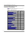
Summary of SNMP Configuration Tasks
Using the BCC and Site Manager ..................................................................................3-2
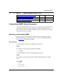
Customizing SNMP Global Parameters ..........................................................................3-3
Disabling and Reenabling SNMP .............................................................................3-3
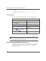
Enabling and Disabling SNMP Lock Mechanism .....................................................3-4
Specifying a Lock Address .......................................................................................3-6
Specifying a Lock Timeout Value .............................................................................3-6
Enabling and Disabling Authentication Failure Traps ...............................................3-7
Specifying the Type of Service for the SNMP Packet ...............................................3-9
vi
303542-A Rev 00
Adding SNMP Communities ...........................................................................................3-9
Specifying an SNMP Community Name ..................................................................3-9
Specifying Community Access Privileges ..............................................................3-10
Deleting an SNMP Community ..............................................................................3-12
Configuring SNMP Community Managers ....................................................................3-13
Adding a Manager ..................................................................................................3-13
Configuring a Manager to Receive Traps ...............................................................3-14
Specifying the Trap Port ...................................................................................3-15
Specifying a Trap Type .....................................................................................3-16
Deleting a Manager ................................................................................................3-17
Configuring Traps on the Router ...................................................................................3-19
Specifying a Trap Entity ..........................................................................................3-19
Specifying the Severity Level for Traps ..................................................................3-21
Disabling a Trap Entity ...........................................................................................3-22
Configuring Trap Exceptions ..................................................................................3-23
Deleting Trap Exceptions .......................................................................................3-25
Configuring Thresholds ................................................................................................3-26
Disabling and Reenabling Thresholds ...................................................................3-27
Setting the Threshold Polling Interval ....................................................................3-27
Adding a Threshold ................................................................................................3-28
Enabling and Disabling Thresholds for a Variable ..................................................3-29
Specifying a Value for the Threshold Level ............................................................3-30
Specifying the Severity Level for Event Messages .................................................3-30
Specifying Threshold Units ....................................................................................3-31
Determining When to Record Threshold Events ....................................................3-32
Specifying Maximum Successive Alarms ...............................................................3-33
Specifying Polling Intervals for Held Variables .......................................................3-34
Specifying a Threshold Object Name .....................................................................3-35
303542-A Rev 00
vii
Chapter 4
Customizing BootP
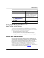
Customizing BootP Relay Agent Parameters .................................................................4-2
Disabling and Reenabling BootP .............................................................................4-2
Specifying Maximum Number of Hops from Client to Server ...................................4-2
Specifying a Minimum Timeout Value ......................................................................4-3
Specifying the Relay Mode for Packet Forwarding ...................................................4-4
Setting Up the Routing Path Between the
BootP Server and the Routers ........................................................................................4-5
Enabling BootP on Router Interfaces .......................................................................4-5
Specifying Interfaces to Receive and Relay
BOOTREQUEST Packets ........................................................................................4-7
Creating a BootP Relay Agent Forwarding Table .....................................................4-8
Specifying the IP Interface Input/Output Address Pair .......................................4-8
Deleting an IP Interface Input/Output Address Pair ...........................................4-9
Disabling BootP Route Forwarding ..................................................................4-10
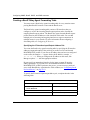
Configuring an AN to Use EZ Install over a Frame Relay PVC ....................................4-11
Creating a BootP Client Interface Table .................................................................4-11
Specifying the Client IP Address .....................................................................4-11
Specifying the DLCI Number ...........................................................................4-12
Specifying Servers for BootP Services .........................................................................4-13
Configuring BootP Preferred Servers .....................................................................4-13
Specifying the Relay Agent IP Address ...........................................................4-14
Specifying the Target Server IP Address .........................................................4-14
Specifying the Target Server’s Host Name ......................................................4-15
Disabling the Forwarding Route ......................................................................4-16
Filtering BootP and DHCP Packets .................................................................4-17
Deleting the BootP Relay Agent from an IP Interface ...................................................4-18
Deleting BootP Globally ................................................................................................4-18
viii
303542-A Rev 00
Chapter 5
Customizing DHCP
Customizing DHCP Parameters .....................................................................................5-1
Specifying Interfaces to Receive and Relay DHCP Packets ....................................5-2
Specifying Servers for DHCP Services ....................................................................5-3
Deleting DHCP from an IP Interface ...............................................................................5-3
Deleting DHCP Globally .................................................................................................5-4
Chapter 6
Customizing RARP
Customizing RARP Parameters .....................................................................................6-2
Disabling and Reenabling RARP Interfaces ...................................................................6-2
Defining the RARP Mapping Table .................................................................................6-3
Specifying the Client’s MAC Address .......................................................................6-3
Specifying the Client’s IP Address ...........................................................................6-4
Disabling RARP Globally ................................................................................................6-5
Deleting RARP Globally .................................................................................................6-5
Appendix A
SNMP, BootP, DHCP, and RARP
Parameter Descriptions
SNMP Global Parameters ............................................................................................. A-3
SNMP Community Parameters ...................................................................................... A-5
SNMP Manager Parameters .......................................................................................... A-6
SNMP Trap Interface Parameters .................................................................................. A-7
SNMP Threshold Global Parameters ............................................................................ A-8
SNMP Threshold Interface Parameters ......................................................................... A-9
BootP and DHCP Parameters ..................................................................................... A-16
BootP Relay Agent Interface Parameters .............................................................. A-16
BootP Address Parameters ................................................................................... A-18
BootP Client Interface Address Parameters .......................................................... A-20
BootP Preferred Server Configuration Parameters ............................................... A-21
RARP Interface Parameters ........................................................................................ A-23
RARP Address Parameters ......................................................................................... A-23
303542-A Rev 00
ix
Appendix B
Default Parameter Settings
SNMP Parameters ......................................................................................................... B-1
BootP and DHCP Parameters ....................................................................................... B-3
RARP Parameters ......................................................................................................... B-4
Index
x
303542-A Rev 00
Figures
Figure 2-1.
Role of SNMP ..........................................................................................2-3
Figure 2-2.
BootP Client and Server on the Same Physical Network ......................2-10
Figure 2-3.
BootP Client and Server on Different Physical Networks .......................2-11
Figure 2-4.
BOOTREQUEST and BOOTREPLY Fields ............................................2-12
Figure 2-5.
Identifying DHCP Servers ......................................................................2-16
Figure 2-6.
Fields in a DHCP Packet ........................................................................2-17
Figure 2-7.
Requesting and Receiving IP Information ..............................................2-18
Figure 2-8.
RARP Server Supplying an IP Address .................................................2-20
Figure 4-1.
Enabling BootP in a Sample Network ......................................................4-6
303542-A Rev 00
xi
Tables
Table 2-1.
Severity Levels ........................................................................................2-5
Table 2-2.
Example of Threshold and Severity Settings ...........................................2-8
Table 3-1.
SNMP Configuration Tasks .....................................................................3-2
Table 3-2.
Trap Types Transmitted by the SNMP Agent ..........................................3-16
Table B-1.
SNMP Global Parameters ..................................................................... B-1
Table B-2.
SNMP Community Parameters ............................................................... B-1
Table B-3.
SNMP Manager Parameters ................................................................... B-2
Table B-4.
SNMP Trap Interface Parameters ........................................................... B-2
Table B-5.
SNMP Threshold Global Parameters ...................................................... B-2
Table B-6.
SNMP Threshold Interface Parameters ................................................. B-2
Table B-7.
BootP Relay Agent Interface Parameters ............................................... B-3
Table B-8.
BootP Address Parameters ..................................................................... B-3
Table B-9.
BootP Client Interface Address Parameters ........................................... B-4
Table B-10.
BootP Preferred Server Configuration Parameters ................................. B-4
Table B-11.
RARP Interface Parameters .................................................................... B-4
Table B-12.
RARP Address Parameters .................................................................... B-4
303542-A Rev 00
xiii
Preface
This guide describes how to configure Simple Network Management Protocol
(SNMP), Bootstrap Protocol (BootP), Dynamic Host Configuration Protocol
(DHCP), and Reverse Address Resolution Protocol (RARP) on Bay Networks®
routers or BayStream™ platforms.
You can use the Bay Command Console (BCC™) or Site Manager to configure
SNMP on a router; you must use Site Manager to configure BootP, DHCP, and
RARP services. In this guide, you will find instructions for using both the BCC
and Site Manager.
Before You Begin
Before using this guide with a new router, you must complete the following
procedures:
•
Install the router (refer to the installation manual that came with your router).
•
Connect the router to the network and create a pilot configuration file (see
Quick-Starting Routers, Configuring BayStack Remote Access, or Connecting
ASN Routers to a Network).
Make sure that you are running the latest version of Bay Networks BayRS™ and
Site Manager software. For information about upgrading BayRS and Site
Manager, see the upgrading guide for your version of BayRS.
303542-A Rev 00
xv
Configuring SNMP, BootP, DHCP, and RARP Services
Text Conventions
This guide uses the following text conventions:
angle brackets (< >)
Indicate that you choose the text to enter based on the
description inside the brackets. Do not type the
brackets when entering the command.
Example: If the command syntax is:
ping <ip_address>, you enter:
ping 192.32.10.12
bold text
Indicates text that you need to enter and command
names and options.
Example: Enter show ip {alerts | routes}
Example: Use the dinfo command.
italic text
Indicates file and directory names, new terms, book
titles, and variables in command syntax descriptions.
Where a variable is two or more words, the words are
connected by an underscore.
Example: If the command syntax is:
show at <valid_route>
valid_route is one variable and you substitute one value
for it.
screen text
Indicates system output, for example, prompts and
system messages.
Example: Set Bay Networks Trap Monitor Filters
separator ( > )
Shows menu paths.
Example: Protocols > IP identifies the IP option on the
Protocols menu.
vertical line ( | )
Separates choices for command keywords and
arguments. Enter only one of the choices. Do not type
the vertical line when entering the command.
Example: If the command syntax is:
show ip {alerts | routes}, you enter either:
show ip alerts or show ip routes, but not both.
xvi
303542-A Rev 00
Preface
Acronyms
ASN.1
abstract syntax notation
BCC
Bay Command Console
BootP
Bootstrap Protocol
DHCP
Dynamic Host Configuration Protocol
IP
Internet Protocol
MAC
media access control
MIB
management information base
RARP
Reverse Address Resolution Protocol
RMON
remote monitoring
SNMP
Simple Network Management Protocol
TFTP
Trivial File Transfer Protocol
UDP
User Datagram Protocol
WAN
wide area network
Bay Networks Technical Publications
You can now print Bay Networks technical manuals and release notes free,
directly from the Internet. Go to support.baynetworks.com/library/tpubs/. Find the
Bay Networks product for which you need documentation. Then locate the
specific category and model or version for your hardware or software product.
Using Adobe Acrobat Reader, you can open the manuals and release notes, search
for the sections you need, and print them on most standard printers. You can
download Acrobat Reader free from the Adobe Systems Web site,
www.adobe.com.
303542-A Rev 00
xvii
Configuring SNMP, BootP, DHCP, and RARP Services
You can purchase Bay Networks documentation sets, CDs, and selected technical
publications through the Bay Networks Collateral Catalog. The catalog is located
on the World Wide Web at support.baynetworks.com/catalog.html and is divided
into sections arranged alphabetically:
•
The “CD ROMs” section lists available CDs.
•
The “Guides/Books” section lists books on technical topics.
•
The “Technical Manuals” section lists available printed documentation sets.
Make a note of the part numbers and prices of the items that you want to order.
Use the “Marketing Collateral Catalog description” link to place an order and to
print the order form.
How to Get Help
For product assistance, support contracts, or information about educational
services, go to the following URL:
http://www.baynetworks.com/corporate/contacts/
Or telephone the Bay Networks Technical Solutions Center at:
800-2LANWAN
xviii
303542-A Rev 00
Chapter 1
Starting SNMP, BootP,
DHCP, and RARP Services
Topic
Page
Starting Configuration Tools
1-2
Configuring IP for Global Protocols
1-2
Starting SNMP Services
1-5
Starting BootP Services
1-7
Starting DHCP Services
1-8
Starting RARP Services
1-10
This chapter describes how to create a basic SNMP, BootP, DHCP, and RARP
configuration by specifying values for required parameters only, and accepting
default values for all other parameters of these services.
For detailed background information about these protocols and how they work,
see Chapter 2. For information on how to customize these protocols by changing
their default values, see Chapters 3 to 6. For information about changing the
default settings, see Appendix A.
303542-A Rev 00
1-1
Configuring SNMP, BootP, DHCP, and RARP Services
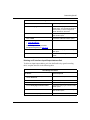
Starting Configuration Tools
Before configuring SNMP, BootP, DHCP, and RARP services, refer to the
following user guides for instructions on how to start and use the Bay Networks
configuration tool of your choice.
Configuration Tool
User Guide
Bay Command Console (BCC)
Using the Bay Command Console
(AN/BN Routers)
Site Manager
Configuring and Managing Routers
with Site Manager
Quick2Config
Configuring Your Router Using the
Quick2Config Tool
NETarchitect
Getting Started with Optivity Network Management
System 8.0
Configuring and Maintaining Networks
with the NETarchitect System
These guides also describe generically how to create or modify a device
configuration.
Configuring IP for Global Protocols
SNMP, BootP, DHCP, and RARP services all use the Internet Protocol (IP) for
message transport. Before you configure SNMP, BootP, DHCP, and RARP
services using the BCC or Site Manager, you must first start IP on the router.
Using Site Manager
Before you can select a protocol to run on the router, you must configure a circuit
that the protocol can use as an interface to an attached network. For information
and instructions, see Configuring WAN Line Services and Configuring Ethernet,
FDDI, and Token Ring Services.
1-2
303542-A Rev 00
Starting SNMP, BootP, DHCP, and RARP Services
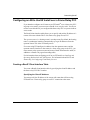
When you have successfully configured the circuit, the Select Protocols window
opens. Proceed as follows:
Site Manager Procedure
You do this
System responds
1. In the Select Protocols window, select IP.
Then click on OK.
The IP Configuration window opens.
2. Set the following parameters:
• IP Address
• Subnet Mask
• Transmit Bcast Addr
• UnNumbered Assoc Address
Click on Help or refer to Configuring IP
Services for parameter descriptions.
3. Click on OK.
You return to the Configuration Manager
window.
Using the BCC
To start IP on the router:
1.
Configure a physical interface on an available slot/connector.
2.
Configure an IP interface on the physical interface.
Step 1: Configuring a Physical Interface
To configure a physical interface on a slot and connector, navigate to the top-level
box prompt and enter:
interface_type slot slot_number connector connector_number
interface_type is the name of a link module on the router.
slot_number is the number of the slot on which the link module is located.
connector_number is the number of a connector on the link module.
For example, the following command configures an Ethernet interface on slot 1,
connector 2.
box# ethernet slot 1 connector 2
ethernet/1/2#
303542-A Rev 00
1-3
Configuring SNMP, BootP, DHCP, and RARP Services
Step 2: Configuring an IP Interface
To configure an IP interface on a physical interface, navigate to the prompt for the
physical interface and enter:
ip address address mask mask
address and mask are a valid IP address and its associated mask, expressed in
either dotted-decimal notation or in bit notation.
For example, the following command configures IP interface 2.2.2.2/255.0.0.0 on
an Ethernet physical interface on slot 1, connector 2.
ethernet/1/2# ip address 2.2.2.2 mask 255.0.0.0
ip/2.2.2.2/255.0.0.0#
An IP interface is now configured on the Ethernet interface with default values for
all interface parameters. When you configure an IP interface, the BCC also
configures IP globally on the router with default values for all IP global
parameters.
You can customize IP by modifying IP global and interface parameters as
described in Configuring IP Services.
1-4
303542-A Rev 00
Starting SNMP, BootP, DHCP, and RARP Services
Starting SNMP Services
You can use the BCC command line interface or the Site Manager graphical user
interface to start SNMP on the router, using default values for all parameters.
Before you begin, verify that you have configured IP on an interface, as described
in “Configuring IP for Global Protocols,” on page 1-2.
Using the BCC
To configure SNMP on the router with default settings, begin in configuration
mode at the box-level prompt:
1.
Configure SNMP.
box# snmp
2.
Display SNMP default settings.
snmp# info
on box
state enabled
lock enabled
lock-address 0.0.0.0
lock-timeout 2
authentication-traps enabled
type-of-service reliability
scope-delimiter 0x40
Using Site Manager
You can easily start SNMP services using default values for all parameters. If you
decide to change some or all of the default values, refer to the instructions in
Chapter 3, “Customizing SNMP.” For a list of SNMP parameters, see Appendix
B, “Default Parameter Settings.”
Before you can start SNMP services, you must verify that you have configured IP
on an interface, as described in “Configuring IP for Global Protocols,” on
page 1-2.
303542-A Rev 00
1-5
Configuring SNMP, BootP, DHCP, and RARP Services
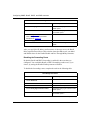
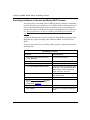
To start SNMP, perform the tasks in the following table:
Site Manager Procedure
You do this
System responds
1. From the Configuration Manager window,
choose Protocols.
The Protocols menu opens.
2. Choose IP.
The IP Global Protocols menu opens.
3. Choose SNMP.
The SNMP menu opens.
4. Choose Global.
The Edit SNMP Global Protocols
Parameter window opens.
5. Accept all default parameter values and
click on OK.
You return to the Configuration Manager
window.
SNMP is now fully operational.
Customizing SNMP Services
The instructions in this chapter show you how to start SNMP using the default
values and settings. For information about modifying SNMP default settings, refer
to Chapter 3, “Customizing SNMP.”
1-6
303542-A Rev 00
Starting SNMP, BootP, DHCP, and RARP Services
Starting BootP Services
You must use Site Manager to start BootP. The BCC is not supported.
Before you can run BootP services, you must enable IP on the router. You can,
however, enable IP and BootP on the router simultaneously. If you want to add
BootP to a circuit on which you have already configured IP, refer to Configuring
and Managing Routers with Site Manager for more information about adding a
protocol.
When you enable BootP, you are required to configure only a few parameters. The
Configuration Manager supplies values for the remaining parameters.
Enabling BootP on an Interface
When you select either a link- or net-module connector, or when you finish
configuring a WAN circuit, the Select Protocols window opens.
Note: The Select Protocols window displays only those protocols that the
circuit type supports.
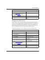
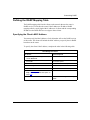
To enable BootP on an interface, complete the tasks in the following table.
Site Manager Procedure
You do this
System responds
The Select Protocols window opens.
1. In the Configuration Manager window,
select the link- or net-module connector on
which you are enabling BootP services.
2. Choose BOOTP.
The BOOTP menu opens.
When you choose BOOTP, you
automatically choose IP.
3. Click on OK.
The IP Configuration window opens.
(continued)
303542-A Rev 00
1-7
Configuring SNMP, BootP, DHCP, and RARP Services
Site Manager Procedure (continued)
You do this
System responds
4. Specify an IP address for this interface.
There is no default for the IP address. You
must supply an address or enter 0.0.0.0 to
indicate that this is an unnumbered
interface. For information about
unnumbered interfaces, see Configuring
IP Services.
5. Edit or accept default values for the
remaining IP interface parameters:
• To accept the default values, click on
OK.
• To edit IP interface parameters, click
on Details. For information about
editing IP interface parameters, see
Configuring IP Services.
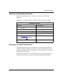
Customizing BootP
For information about customizing BootP parameters, see Chapter 4,
“Customizing BootP.”
Starting DHCP Services
Before you can enable DHCP services, you must enable IP and BootP on the
router. You can, however, enable IP, BootP, and DHCP on the router
simultaneously. If you want to add BootP and DHCP to a circuit on which you
have already configured IP, see Configuring and Managing Routers with Site
Manager for information about adding a protocol.
When you enable BootP and DHCP, you are required to configure only a few
parameters. The Configuration Manager supplies default values for the remaining
parameters.
1-8
303542-A Rev 00
Starting SNMP, BootP, DHCP, and RARP Services
Enabling DHCP on an Interface
When you select either a link- or net-module connector, or when you finish
configuring a WAN circuit, the Select Protocols window opens.
Note: The Select Protocols window displays only those protocols that the
circuit type supports.
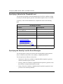
To enable DHCP on an interface, complete the tasks in the following table.
Site Manager Procedure
You do this
For instructions, see
1. Enable BootP on the interface.
“Enabling BootP on an Interface” on page
1-7.
2. Access the BootP Relay Agent Interface
Table window.
“Customizing BootP Relay Agent
Parameters” on page 4-2.
3. Set the Pass Through Mode parameter to “Specifying the Relay Mode for Packet
DHCP, or to BootP and DHCP. This action Forwarding” on page 4-4.
allows you to select either DHCP, or BootP
and DHCP, for the Pass Through Mode
parameter in other windows.
4. Click on Apply.
5. Edit the other parameters in this window.
“Customizing BootP Relay Agent
Parameters” on page 4-2.
Customizing DHCP
For information about modifying DHCP parameters, see Chapter 5,
“Customizing DHCP.”
303542-A Rev 00
1-9
Configuring SNMP, BootP, DHCP, and RARP Services
Starting RARP Services
Before you can enable RARP services, you must enable IP on the router. You can,
however, enable IP and RARP services on the router simultaneously. If you want
to add RARP to a circuit on which you have already configured IP, see
Configuring and Managing Routers with Site Manager for information about
adding a protocol.
When you enable RARP services, you are required to configure only a few
parameters. The Configuration Manager supplies default values for the remaining
parameters.
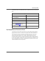
Enabling RARP on an Interface
When you select either a link- or net-module connector, or when you finish
configuring a WAN circuit, the Select Protocols window opens.
Note: The Select Protocols window displays only those protocols that the
circuit type supports.
To enable RARP on an interface, complete the tasks in the following table.
Site Manager Procedure
You do this
System responds
The Select Protocols window opens.
1. In the Configuration Manager window,
select the link- or net-module connector on
which you are enabling RARP services.
2. Choose Reverse ARP.
When you choose Reverse ARP, you
automatically choose IP.
3. Click on OK.
The IP Configuration window opens.
(continued)
1-10
303542-A Rev 00
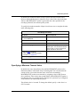
Starting SNMP, BootP, DHCP, and RARP Services
Site Manager Procedure (continued)
You do this
System responds
4. Specify an IP address for this interface.
There is no default for the IP address. You
must supply an address or enter 0.0.0.0 to
indicate that this is an unnumbered
interface. For information about
unnumbered interfaces, see Configuring
IP Services.
5. Edit or accept default values for the
remaining IP interface parameters.
• To accept the default values, click on
OK.
• To edit IP interface parameters, click
on Details. For information about
editing IP interface parameters, see
Configuring IP Services.
Customizing RARP
For information about modifying RARP parameters, refer to Chapter 6,
“Customizing RARP.”
303542-A Rev 00
1-11
Chapter 2
SNMP, BootP,
DHCP, and RARP Concepts
Topic
Page
SNMP Overview
2-1
SNMP Implementation Notes
2-4
BootP Relay Agent Overview
2-10
DHCP Overview
2-14
RARP Overview
2-20
This chapter describes the concepts behind SNMP, BootP, DHCP, and RARP
services and how we implement them in Bay Networks routers. You can use this
information to decide how to customize SNMP, BootP, DHCP, and RARP
parameters for your system.
SNMP Overview
SNMP is a simple request/response protocol that communicates management
information between two types of SNMP software entities: SNMP applications
(also called SNMP managers) and SNMP agents.
303542-A Rev 00
2-1
Configuring SNMP, BootP, DHCP, and RARP Services
SNMP applications contain manager software that runs on a network management
station (also known as an SNMP client), such as a PC or a workstation. The
manager software implements the protocols used to exchange data with SNMP
agents. SNMP applications issue queries to gather information about the status,
configuration, and performance of external network devices, called network
elements in SNMP terminology. Network elements contain an agent and perform
the network management function that the network management stations request.
The Bay Networks Site Manager software is an example of a network
management station, and the Bay Networks Backbone Node (BN®) router is an
example of a network element.
The SNMP agent is a software entity that responds to information and action
request messages (SNMP Set and Get requests) sent by a network management
station (your Site Manager workstation). The messages exchanged between
manager and router SNMP agents enable you to access and manage objects in an
active or inactive (stored) management information base (MIB) on a router.
The agents also send unsolicited reports (called traps) back to the network
management station when certain network activity occurs. An example of a trap is
an overload condition as defined by the packet load’s crossing some threshold.
You use the management station to configure, monitor, and receive trap messages
from other network devices configured as SNMP agents. The management station
can get and set objects in the agents and can receive traps from the agents. The
management station, therefore, has the capability to “manage” a number of
agents.
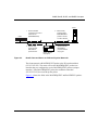
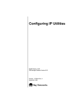
SNMP Messages
SNMP managers and network elements communicate with each other by
sending SNMP messages (Figure 2-1). The management station issues three types
of SNMP messages to retrieve single or multiple object variables:
•
GetRequest messages
•
GetNextRequest messages
•
SetRequest messages
The agent acknowledges all three types of messages by passing a Get Response
message to the management application. In addition, an agent may issue a trap to
the network management station to identify a condition, such as a threshold that
exceeds a predefined value.
2-2
303542-A Rev 00
SNMP, BootP, DHCP, and RARP Concepts
SNMP management station
SNMP agent
Managed resources
SNMP manager
Trap
GetResponse
SetRequest
GetNextRequest
GetRequest
SNMP managed objects
Application
manages objects
Trap
GetResponse
SetRequest
GetNextRequest
GetRequest
Management application
SNMP agent
SNMP messages
UDP
UDP
IP
IP
Network-dependent protocols
Network-dependent protocols
Network or
internetwork
SNM00012A
Figure 2-1.
Role of SNMP
SNMP Communities
For security reasons, the SNMP agent validates each request from an SNMP
manager before responding to the request, by verifying that the manager belongs
to a valid SNMP community.
303542-A Rev 00
2-3
Configuring SNMP, BootP, DHCP, and RARP Services
An SNMP community is a logical relationship between an SNMP agent and one
or more SNMP managers. You define communities locally at the agent. The agent
establishes one community for each desired combination of authentication and
access control characteristics. You assign each community a unique name (within
the agent), and all members of a community have the same access privileges,
either read-only or read-write:
•
Read-only: members can view configuration and performance information.
•
Read-write: members can view configuration and performance information,
and also change the configuration.
By defining a community, an agent limits access to its MIB, to a selected set of
management stations. By using more than one community, the agent can provide
different levels of MIB access to different management stations.
All SNMP message exchanges consist of a community name and a data field,
which contains the SNMP operation and its associated operands. You can
configure the SNMP agent to receive requests and send responses only from
managers that are members of a known community.
If the agent knows the community name in the SNMP message and knows that the
manager generating the request is a member of that community, it considers the
message to be authentic and gives it the access allowed for members of that
community. In this way, the SNMP community prevents unauthorized managers
from viewing or changing the configuration of a router.
SNMP Implementation Notes
This section contains information about features specific to the Bay Networks
implementation of SNMP.
Internet Protocol
SNMP uses the User Datagram Protocol (UDP) to transport its messages. You
must enable the Internet Protocol (IP) to use UDP and SNMP.
Events and Traps
An event is a change in the operating status of a router. The router stores the event
as a single entry in a memory-resident log.
2-4
303542-A Rev 00
SNMP, BootP, DHCP, and RARP Concepts
An event log message provides a brief description of an event, along with the
event code associated with that event.
A trap is an event that the router transmits to the network management station.
SNMP allows you to configure which event log messages the agent sends to the
network management station as traps. You select these traps based on slot,
protocol entity, and severity level. You can also specify up to 50 exceptions, which
are traps that the agent always sends, or never sends, regardless of slot and
regardless of how you configure the trap parameters. For information about how
to specify which traps the agent sends, see “Configuring Traps on the Router” on
page 3-19.
Protocol Entities
Events are always associated with a particular protocol entity. An entity is the
software that generates a message. Entities include Bay Networks software
dedicated to the operation of a software service, such as Trivial File Transfer
Protocol (TFTP) and IP, and the GAME® operating system.
Both events and entities are assigned entity codes. Together, this pair uniquely
identifies a Bay Networks router platform event. For a complete list of entities
(both their abbreviations and full names) and associated entity codes, see Event
Messages for Routers.
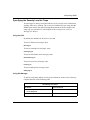
Severity Levels
Event and trap messages are always associated with a severity level. Table 2-1
describes the severity levels and gives the code that corresponds to each one. This
guide does not cover Debug messages, because they are for Bay Networks internal
use only.
Table 2-1.
Severity Levels
Severity
Description
Code
Information
Indicates routine events that usually require no action.
2
Warning
Indicates that a service acted in an unexpected manner.
4
Fault
Indicates a major service disruption, usually caused by a
configuration, network, or hardware problem. The entities
involved keep restarting until the problem is resolved.
8
(continued)
303542-A Rev 00
2-5
Configuring SNMP, BootP, DHCP, and RARP Services
Table 2-1.
Severity Levels (continued)
Severity
Description
Code
Trace
Indicates information about each packet that traversed the
network. Bay Networks recommends viewing this type of trap
message only when diagnosing network problems.
10
Debug
Indicates information that Bay Networks Customer Support
uses. These messages are not documented.
1
For detailed information about entities and severity levels, see Event Messages for
Routers.
SNMP Trap Format
Some third-party network management applications, such as NetExpert,
OpenView, and SunNet, let you trigger an operation when a specific SNMP trap is
received. This section describes the SNMP trap format.
The router platform transmits a Bay Networks event log trap as a 32-bit value as
follows:
•
Octets 1 and 2 (the most significant 16 bits) of the specific trap ID contain
values of 1 and 0, respectively, to identify a Bay Networks event log trap.
•
Octet 3 of the specific trap ID contains a code that identifies the software
entity that generated the trap.
•
Octet 4 of the specific ID contains the event code that, in conjunction with the
entity code, uniquely identifies the event.
Each 32-bit value is accompanied by three variable bindings that convey the event
string that describes the trap condition, the slot that hosts the entity that generated
the trap, and the trap severity (see Table 2-1).
For detailed information about the SNMP trap format, see Event Messages for
Routers.
2-6
303542-A Rev 00
SNMP, BootP, DHCP, and RARP Concepts
Thresholds
SNMP uses a management information base (MIB) to manage the router. The
MIB includes an extensive collection of statistics (MIB variables) that track the
router’s performance and provide early warnings of abnormal operating
conditions.
With the Site Manager threshold feature, you can configure the agent to
automatically notify you when specific statistics (or instances of the variable)
reach certain levels.
You can set a threshold for any integer, counter, gauge, or time-tick variable in the
MIB. Using the threshold parameters, you:
•
Select the polling interval, which specifies how often the agent checks the
statistic to see if its value has reached the threshold.
•
Set three threshold values (high, medium, and low).
•
Specify the threshold action as Lessthan or Greaterthan.
For information about setting thresholds, see “Configuring Thresholds” on
page 3-26.
When the statistic reaches the threshold, the agent generates an event. You specify
the severity level at which you want the manager to log the event. Table 2-1 shows
the available severity levels and their suggested meanings. Depending on how you
configure the SNMP trap parameters (see “Configuring Traps on the Router” on
page 3-19), the agent may also send the threshold exception as an SNMP trap.
The Site Manager threshold feature is functionally similar to the RMON Alarm
and Event facility, except for some minor differences. The Site Manager threshold
feature provides three-tiered thresholds and defines a user-definable hysteresis
mechanism. The RMON Alarm and Event facility provides a two-tiered
proprietary threshold system. For information on RMON, RMON 2, and RMON
alarms and events, see Configuring RMON and RMON 2 for BayRS Routers.
303542-A Rev 00
2-7
Configuring SNMP, BootP, DHCP, and RARP Services
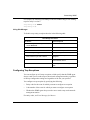
Threshold Example
Suppose you want SNMP to warn you if the number of high-priority (Priority
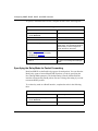
Level 1) packets queued for transmission is approaching the maximum number
supported by an interface. This maximum value is specified by the
wfCctOptsCngcCfgQp1Threshold MIB object. Using the threshold parameters,
you set a threshold for wfCctOptsCngcCfgQp1Threshold equal to 205.
You also set the polling interval to 20 seconds to indicate that, every 20 seconds,
the agent should check variables for which you have configured thresholds. You
set the threshold action to Greaterthan and set the threshold levels and severity of
events to the values shown in Table 2-2.
Table 2-2.
Threshold
Level
Example of Threshold and Severity Settings
Low
Medium
High
Depth of Priority 102
(40% of capacity)
1 transmit
queue
153
(60% of capacity)
205
(80% of capacity)
Severity of event INFO
INFO
WARNING
When you add this threshold to the MIB, the agent polls the variable
wfCctOptsCngcCfgQp1Threshold every 20 seconds and responds as follows:
•
If its value is greater than 102, but less than or equal to 153, the manager logs
an informational event indicating that the queue depth exceeded the low
threshold.
•
If its value is greater than 153 but less than or equal to 205, the manager logs
an informational event indicating that the queue depth exceeded the medium
threshold.
•
If its value is greater than 205, the manager logs a warning event indicating
that the queue depth exceeded the high threshold.
Event Message Format
By default, the threshold event messages include the MIB object identifier (OID)
of the variable that exceeded the threshold, the value of the variable, and the
threshold level exceeded.
2-8
303542-A Rev 00
SNMP, BootP, DHCP, and RARP Concepts
For example, if the wfCctOptsCngcCfgQp1Threshold variable has a value of 120,
the agent generates an event message similar to the following:
#1:08/27/96 10:53:20.802 INFO SLOT 2 STA CODE: 6
Object 1.3.6.1.4.1.18.3.5.1.4.10.1.24 with value = 120 units/ hour
is > low threshold.
You can, however, identify objects more easily by configuring the software to
report the object name rather than the OID in the event message. To configure the
software to report the object name in the event message, use the Threshold Label
parameter (see page A-15).
For example, if you set the Threshold Label parameter to
wfCctOptsCngcCfgQp1Threshold, the agent generates an event message similar
to the following:
#1:08/27/96 10:53:20.802 INFO SLOT 2 STA CODE: 6
Object wfCctOptsCngcCfgQp1Threshold with value = 120 units/ hour is
> low threshold.
State of a Threshold
If the collision rate stays above a threshold for an extended period of time, the
agent continues to generate a new event every 5 seconds. You can specify the
maximum number of event messages you want the agent to generate before it
changes the threshold’s state to held.
When the threshold is in a held state, the agent does not generate new events
unless the statistic exceeds the threshold at a different level. If the statistic does
not exceed any threshold for a specified number of polling periods, the agent no
longer considers the threshold held.
Memory Considerations
Polling statistics to determine whether they have reached a threshold and reporting
events when variables exceed thresholds require router processing capacity. When
you set many thresholds and use shorter polling intervals, the router performance
will probably decline.
303542-A Rev 00
2-9
Configuring SNMP, BootP, DHCP, and RARP Services
BootP Relay Agent Overview
BootP is built on the client-server model and allows a diskless client to boot
remotely from a server on the same network or on a different physical network.
The client broadcasts a request to boot from a remote server. When a suitable
server receives the BOOTREQUEST packet, it responds to the client by issuing a
BOOTREPLY packet, which includes the client’s IP address, the address of the
gateway, and the address of a server. The server then transmits the boot file to the
client via a transfer protocol, such as Trivial File Transfer Protocol (TFTP).
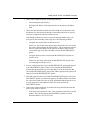
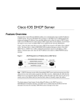
Figure 2-4 illustrates how BootP works when the client and the server are on the
same network. The client transmits a BOOTREQUEST packet to the IP broadcast
address (255.255.255.255). The server sends a BOOTREPLY packet to the client.
Depending on the server’s implementation, the server addresses the packet to
either the broadcast or the client’s IP address.
Client broadcasts a request
to boot from a remote server
(BOOTREQUEST).
Server sends acknowledgment
to the client (BOOTREPLY).
Client
Server
SNM0002A
Figure 2-2.
BootP Client and Server on the Same Physical Network
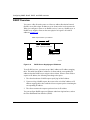
If, however, the client and the server are on different physical networks, a BootP
relay agent (also known as a BootP gateway) must forward BootP packets to their
correct destinations. When you configure a Bay Networks router for BootP
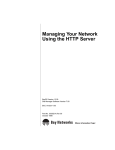
services, the router acts as a BootP relay agent. Figure 2-3 illustrates how BootP
works when the client and the server are on different physical networks.
2-10
303542-A Rev 00
SNMP, BootP, DHCP, and RARP Concepts
Server
Client
Figure 2-3.
1. Client broadcasts
a request to boot from a
remote server
(BOOTREQUEST).
2. BOOTP relay
agent transmits
BOOTREQUEST
packet to servers
on other networks.
4. BOOTP relay
agent transmits
BOOTREPLY
packet to client.
3.
Router (BOOTP
relay agent)
Server transmits
BOOTREPLY
packet to BOOTP
relay agent.
BootP Client and Server on Different Physical Networks
The client transmits a BOOTREQUEST packet to the IP broadcast address
(255.255.255.255). The router receives the BOOTREQUEST packet at an
interface that you configured to receive BOOTREQUEST packets (an input
interface). If the BOOTREQUEST packet has an address other than
255.255.255.255, the router drops the packet.
Figure 2-4 shows the fields in the BOOTREQUEST and BOOTREPLY packets.
303542-A Rev 00
2-11
Configuring SNMP, BootP, DHCP, and RARP Services
Operation (1)*
Hardware type (1)
Hardware address
length (1)
Hops (1)
Transaction ID (4)
Flags (2)
Seconds (2)
Client IP address (4)
Your IP address (4)
Server IP address (4)
Gateway IP address (16)
Client hardware address (16)
Server name (64)
File name (128)
Vendor-specific area (64)
*The number in parentheses indicates the number of octets in each field.
SNM0001A
Figure 2-4.
BOOTREQUEST and BOOTREPLY Fields
The packet relay process uses these fields as follows:
1. When a router interface receives a BOOTREQUEST packet, the router
examines the seconds and hops fields in the packet and compares these values
to BootP parameters you configured on that interface.
The seconds field contains the minimum number of seconds that the router
waits before forwarding a BOOTREQUEST packet. If the value in the
seconds field of the packet is less than the value of the Timeout Secs.
parameter you configured on the interface, the router drops the packet.
The hops field contains the maximum number of hops that a packet can take
between the source and destination devices. If the packet has traversed more
hops than the value of the hops parameter you specified for that interface, the
router drops the packet.
2-12
303542-A Rev 00
SNMP, BootP, DHCP, and RARP Concepts
2. If the router accepts the packet, it alters the packet by:
•
Incrementing the hops field by 1
•
Writing the IP address of the input interface to the gateway IP address
field
3. The router then determines which networks should receive this packet and
broadcasts it to other networks through a forwarding route that you specify
when you configure the router for BootP services.
If the BootP packet has to travel to a network through another router, you
must specify the forwarding route using one of the following methods:
•
Configure the second router for BootP services.
In this case, the second router inspects the packet in the same way as the
first router, and increments the hops field by 1. The second router will not,
however, replace the address in the gateway IP address field, because
servers will reply to the first router that received the BOOTREQUEST
packet.
•
Configure the first router to forward the BOOTREQUEST packet to a
specific server.
In this case, the router will unicast the BOOTREQUEST packet to the
server through normal IP services.
4. Servers on other networks receive the BOOTREQUEST packet and respond
with a BOOTREPLY packet. Those servers transmit the BOOTREPLY
packets through normal IP services to the address of the first interface that
received the BOOTREQUEST packet. That address appears in the gateway IP
address field in the BOOTREQUEST packet.
5. When the router that first received the BOOTREQUEST packet receives the
BOOTREPLY packet, it examines the gateway IP address field to check that
the value in this field is the same as the IP destination address that the server
used for the packet. If the addresses differ, the router discards the
BOOTREPLY packet.
6. If the router accepts the packet, it examines the flags field and forwards the
packet to the client as follows:
•
303542-A Rev 00
If the flags field contains the value 1, the client does not know its own IP
address. The router broadcasts the BOOTREPLY packets to the IP
broadcast address (255.255.255.255).
2-13
Configuring SNMP, BootP, DHCP, and RARP Services
•
If the flags field contains the value 0, the client knows its own IP address,
which appears in the client IP address field of the BOOTREPLY packet.
The router sends the BOOTREPLY packet to that IP address and the
link-layer address that appears in the client hardware address field.
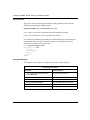
DHCP Overview
DHCP is an extension of BootP and is also built on the client-server model. DHCP
provides a method for dynamically assigning IP addresses and configuration
parameters to other IP hosts or clients in an IP network. DHCP is specifically
designed for servers in large network environments and complex TCP/IP software
configurations.
DHCP allows a host to automatically allocate reusable IP addresses and additional
configuration parameters for client operation, and allows the client-server host to
configure parameters not directly related to the IP protocol. This feature allows
the host to exchange packets with any other host on the network.
DHCP enables clients to obtain an IP address for a fixed length of time (a lease
period) from remote servers (DHCP servers). Groups of hosts that do not need
permanent IP addresses can lease an address from a limited pool of addresses. The
lease period can range from 1 minute to 99 years. When the lease period expires,
the server can assign the IP address to another client on the network. DHCP also
enables clients to acquire the IP configuration parameters they need to
communicate on a network.
The DHCP packet format is based on a BootP packet. As a result, DHCP uses the
BootP relay agent to forward DHCP packets. This scheme provides
interoperability between the existing BootP clients and DHCP servers. The BootP
relay agent uses the same criteria and methods for forwarding both DHCP and
BootP packets. For information about the packet relay process, see “BootP Relay
Agent Overview,” on page 2-10.
2-14
303542-A Rev 00
SNMP, BootP, DHCP, and RARP Concepts
Although BootP and DHCP use the same UDP port numbers (67 and 68), they
differ in the following ways:
•
DHCP defines a mechanism for clients to obtain their IP network address for a
fixed period of time (lease), allowing for reassignment of expired IP network
addresses to different clients.
•
DHCP provides a mechanism for clients to acquire all of the IP configuration
parameters needed to communicate on a network.
•
DHCP packet length is longer than for BootP.
The additional packet length allows a DHCP server to provide the client with
all the IP configuration parameters that it needs to operate.
•
DHCP is a more complicated protocol than BootP.
DHCP has seven message types; BootP uses only two.
Acquiring a New IP Address and New Configuration Parameters
DHCP acquires an IP address and other configuration parameters for clients. This
process involves the following stages:
•
•
•
303542-A Rev 00
Identifying DHCP servers
Requesting and receiving IP information
Accepting or declining IP information
2-15
Configuring SNMP, BootP, DHCP, and RARP Services
Identifying DHCP Servers
Figure 2-5 shows the first stage of the process of acquiring a new IP address.
.
Server
1. Client broadcasts
a DHCPDISCOVER
packet.
2. BOOTP relay agent
transmits the
DHCPDISCOVER
packet to servers
on other networks.
4. BOOTP relay
agent transmits
DHCPOFFER
packets to client.
3.
Client
Router (BOOTP
relay agent)
Servers transmit
DHCPOFFER
packets to BOOTP
relay agent.
SNM0005A
Figure 2-5.
Identifying DHCP Servers
To identify DHCP servers, the client broadcasts a DHCPDISCOVER packet.
Figure 2-6 shows the fields in a DHCP packet. The packet relay process uses these
fields as follows:
1. A BootP relay agent receives the packet and, if it accepts the packet, transmits
it to DHCP servers on other networks.
2-16
303542-A Rev 00
SNMP, BootP, DHCP, and RARP Concepts
Operation (1) *
Hardware type (1)
Hardware address
length (1)
Hops (1)
Transaction ID (4)
Flags (2)
Seconds (2)
Client IP address (4)
Your IP address (4)
Server IP address (4)
Gateway IP address (16)
Client hardware address (16)
Server name (64)
File name (128)
Options (312)
* The number in parentheses indicates the number of octets in each field.
SNM0004A
Figure 2-6.
Fields in a DHCP Packet
2. DHCP servers may respond with a DHCPOFFER packet that includes an
available IP address in the IP address field.
When a DHCP server offers an IP address, that address is temporarily
unavailable to other clients. If the client does not accept or reject the address
within a certain period of time, the server reclaims it. The address is then
available for other clients.
3. The BootP relay agent receives the DHCPOFFER packet and examines the
packet. If the BootP relay agent accepts the packet, it forwards it to the client.
4. If a client does not receive a DHCPOFFER packet within a specified amount
of time after broadcasting a DHCPDISCOVER packet, it sends the packet
again. The client will rebroadcast the packet up to 10 times.
The client may receive DHCPOFFER packets from several potential servers.
If you configure the client to wait for multiple responses, it compares
configuration parameters in the DHCPOFFER packets to decide which server
to target.
303542-A Rev 00
2-17
Configuring SNMP, BootP, DHCP, and RARP Services
Requesting and Receiving IP Information
Figure 2-7 shows the next stage of the process of acquiring a new IP address.
Server
1. Client broadcasts
a DHCPREQUEST
packet.
2. BOOTP relay agent
transmits DHCPREQUEST
packet to all servers
that supplied a
DHCPOFFER packet.
4. BOOTP relay agent
transmits DHCPACK
or DHCPNAK
packet to client.
3. Target server transmits
DHCPACK or DHCPNAK
packet to BOOTP relay
agent.
Client
Router (BOOTP
relay agent)
SNM0006A
Figure 2-7.
Requesting and Receiving IP Information
1.
When the client has chosen a target server, it broadcasts a DHCPREQUEST
packet. The DHCPREQUEST packet contains the address of the target server
in the server IP address field.
2. The router receives the packet and forwards it to all servers.
3. Those servers examine the packet, and if their IP addresses differ from the
value in the server IP address field, they reclaim the IP addresses they
supplied in the DHCPOFFER packets. These addresses are now available for
other clients.
Accepting or Declining IP Information
The target server recognizes its IP address in the server IP address field, and
responds to the DHCPREQUEST packet as follows:
•
2-18
If the target server can supply the requested configuration parameters, it sends
a DHCPACK packet to the client through the BootP relay agent.
303542-A Rev 00
SNMP, BootP, DHCP, and RARP Concepts
The client examines the configuration parameters in the DHCPACK packet
and records the duration of the lease period. If the client detects a problem
with the configuration parameters, it sends a DHCPDECLINE packet to the
server and issues a new DHCPDISCOVER packet. Otherwise, the client
accepts the configuration parameters.
•
If the target server cannot supply the requested configuration parameters, it
sends a DHCPNAK packet to the client through the BootP relay agent.
When the client receives the DHCPNAK packet, it broadcasts a new
DHCPDISCOVER packet and the process begins again.
A client may choose to relinquish its IP address before the lease period expires by
sending a DHCPRELEASE packet to the server. This packet contains the
relinquished IP address in the client IP address field and the client’s MAC address
in the client hardware address field.
Acquiring the Same IP Address Again
A client may want to reuse an IP address that a server allocated earlier by DHCP.
In this case, the interchange between client and server omits some of the steps
described in the previous section, and proceeds as follows:
1. The client starts the interchange by broadcasting a DHCPREQUEST packet
that contains its previous IP address in the client IP address field.
2. The BootP relay agent forwards the packet to DHCP servers on other
networks.
3. DHCP servers examine the client’s configuration parameters in the options
field of the DHCPREQUEST packet.
4. The server that originally supplied the configuration parameters recognizes
them and responds with a DHCPACK packet.
5. When a client receives a DHCPACK packet, it accepts or declines the
parameters, as it would when receiving a new IP address.
If a client’s request is invalid (for example, when the client has moved to a new
network), servers respond with a DHCPNAK packet. If a client receives only
DHCPNAK packets, it must request a new IP address by broadcasting a
DHCPDISCOVER packet.
303542-A Rev 00
2-19
Configuring SNMP, BootP, DHCP, and RARP Services
RARP Overview
You can use a Bay Networks router as a Reverse Address Resolution Protocol
(RARP) server that assigns IP addresses to its clients on the local area network.
When you configure a router to use RARP services, it acts as a RARP server. A
RARP server supplies clients on the same physical or logical LAN with IP
addresses (Figure 2-8).
RARP request: What is my IP address?
RARP response: 192.32.2.23
Router (RARP server)
Server
SNM0007A
Figure 2-8.
RARP Server Supplying an IP Address
To use RARP services, you must set up a MAC address-to-IP address mapping
table. This table lists the MAC addresses of clients and the corresponding IP
addresses that the RARP server assigns to those clients. When a client needs to
acquire an IP address, the following interchange takes place:
1. The client broadcasts a RARP request specifying its MAC address.
2. Upon receiving a RARP request, the router refers to its MAC address-to-IP
address mapping table, then sends the client a response packet containing the
corresponding IP address.
3. The client examines the response packet to learn its IP address.
You can configure RARP support on Ethernet and token ring interfaces, and on
the Fiber Distributed Data Interface (FDDI).
2-20
303542-A Rev 00
Chapter 3
Customizing SNMP
Topic
Page
Summary of SNMP Configuration Tasks Using the BCC and Site Manager
3-2
Customizing SNMP Global Parameters
3-3
Adding SNMP Communities
3-9
Configuring SNMP Community Managers
3-13
Configuring Traps on the Router
3-19
Configuring Thresholds
3-26
This chapter describes how to customize SNMP services. It assumes you have
configured an IP interface using the default parameters, as described in Chapter 1,
and that you understand the SNMP concepts in Chapter 2.
303542-A Rev 00
3-1
Configuring SNMP, BootP, DHCP, and RARP Services
Summary of SNMP Configuration Tasks
Using the BCC and Site Manager
Table 3-1 summarizes SNMP configuration tasks and indicates whether you can
use the BCC or Site Manager to perform each task.
Table 3-1.
SNMP Configuration Tasks
Task
BCC
Site Manager
Disabling and Reenabling SNMP
✓
✓
Enabling and Disabling SNMP Lock Mechanism
✓
✓
Specifying a Lock Address
✓
✓
Specifying a Lock Timeout Value
✓
✓
Enabling and Disabling Authentication Failure Traps
✓
✓
Specifying the type of service for SNMP packets
✓
Specifying an SNMP Community Name
✓
✓
Specifying Community Access Privileges
✓
✓
Deleting an SNMP Community
✓
✓
Adding a Manager
✓
✓
Configuring a Manager to Receive Traps
✓
✓
Deleting a Manager
✓
✓
Specifying a Trap Entity
✓
✓
Specifying the Severity Level for Traps
✓
✓
Disabling a Trap Entity
✓
✓
Configuring Trap Exceptions
✓
✓
Deleting Trap Exceptions
✓
✓
Disabling and Reenabling Thresholds
✓
Setting the Threshold Polling Interval
✓
Adding a Threshold
✓
Enabling and Disabling Thresholds for a Variable
✓
Specifying a Value for the Threshold Level
✓
Specifying the Severity Level for Event Messages
✓
Specifying Threshold Units
✓
(continued)
3-2
303542-A Rev 00
Customizing SNMP
Table 3-1.
SNMP Configuration Tasks (continued)
Determining When to Record Threshold Events
✓
Specifying Maximum Successive Alarms
✓
Specifying Polling Intervals for Held Variables
✓
Specifying a Threshold Object Name
✓
Customizing SNMP Global Parameters
You can enable SNMP services most easily by accepting all the default parameter
values. However, you may want to change these values, depending on your
network requirements. This chapter describes choices you can make to use SNMP
most effectively on your network.
Disabling and Reenabling SNMP
When you enable IP on an interface, SNMP access is automatically enabled
through that interface, and default values are in effect for all SNMP parameters
(see Appendix B for parameter defaults).
Using the BCC
To disable SNMP, navigate to the SNMP prompt and enter:
disable
For example, the following command disables SNMP:
snmp# disable
To reenable SNMP, navigate to the SNMP prompt and enter:
enable
For example, the following commands reenable SNMP and display its default
values:
snmp# enable
snmp# info
on box
state enabled
lock enabled
lock-address 0.0.0.0
303542-A Rev 00
3-3
Configuring SNMP, BootP, DHCP, and RARP Services
lock-timeout 2
authentication-traps enabled
type-of-service reliability
scope-delimiter 0x40 (=> This function is not available)
snmp#
Using Site Manager
To disable and reenable SNMP, complete the tasks in the following table.
Site Manager Procedure
You do this
System responds
1. In the Configuration Manager window,
choose Protocols.
The Protocols menu opens.
2. Choose IP.
The IP menu opens.
3. Choose SNMP.
The SNMP menu opens.
4. Choose Global.
The Edit SNMP Global Parameters
window opens.
5. Set the Enable parameter.
Click on Help or see the parameter
description on page A-3.
6. Click on OK.
You return to the Configuration Manager
window.
Caution: When you disable the SNMP agent in dynamic mode, you
immediately prohibit Site Manager from communicating with the router and
will disconnect your Site Manager session.
Enabling and Disabling SNMP Lock Mechanism
The SNMP locking mechanism prohibits the SNMP agent from responding to
multiple network management stations issuing simultaneous SNMP set
commands to the router.
3-4
303542-A Rev 00
Customizing SNMP
The SNMP locking mechanism is enabled by default. This means that the SNMP
agent identifies the station from which it receives the next SNMP set command
and, for a time equal to the value of the Lock TimeOut parameter, responds only
to SNMP set commands from that station. If the agent receives an SNMP set
command from another network management station during this time, it issues an
SNMP genErr GetResponse PDU, which that station logs as an SNMP Set Error
message.
To allow the SNMP agent to respond to simultaneous SNMP set commands from
multiple network management stations, set the SNMP locking mechanism to
Disable.
Using the BCC
To disable the mechanism, navigate to the SNMP prompt and enter:
lock disabled
To reenable the lock mechanism, navigate to the SNMP prompt and enter:
lock enabled
Using Site Manager
To enable and disable the SNMP lock mechanism, complete the tasks in the
following table.
Site Manager Procedure
You do this
System responds
1. In the Configuration Manager window,
choose Protocols.
The Protocols menu opens.
2. Choose IP.
The IP menu opens.
3. Choose SNMP.
The SNMP menu opens.
4. Choose Global.
The Edit SNMP Global Parameters
window opens.
5. Set the Use Lock parameter.
Click on Help or see the parameter
description on page A-3.
6. Click on OK.
303542-A Rev 00
You return to the Configuration Manager
window.
3-5
Configuring SNMP, BootP, DHCP, and RARP Services
Specifying a Lock Address
The default lock address is 0.0.0.0. To specify a lock address, navigate to the
SNMP prompt and enter:
lock-address address
address is an IP address in dotted-decimal notation.
Note: There is no Site Manager command for specifying a lock address.
Specifying a Lock Timeout Value
If the SNMP locking mechanism is enabled, you can customize the lock timeout
period. The lock timeout period is the maximum number of minutes the SNMP
agent allows an idle network management station to hold a lock on it. During this
time, the SNMP agent locks out SNMP set commands from other network
management stations. The lock timer is reset each time the locking manager issues
an SNMP set command.
By default, the SNMP agent allows an idle network management station to hold a
lock on it for 2 minutes. To change the default lock timeout period, specify a value
from 1 to 60 minutes.
Using the BCC
To specify the number of seconds, navigate to the SNMP prompt and enter:
lock-timeout integer
integer is the number of seconds.
3-6
303542-A Rev 00
Customizing SNMP
Using Site Manager
To specify a lock timeout value, complete the tasks in the following table.
Site Manager Procedure
You do this
System responds
1. In the Configuration Manager window,
choose Protocols.
The Protocols menu opens.
2. Choose IP.
The IP menu opens.
3. Choose SNMP.
The SNMP menu opens.
4. Choose Global.
The Edit SNMP Global Parameters
window opens.
5. Set the Lock Time Out parameter.
Click on Help or see the parameter
description on page A-4.
6. Click on OK.
You return to the Configuration Manager
window.
Enabling and Disabling Authentication Failure Traps
The router generates an authentication failure trap when it receives an SNMP
message from an SNMP manager falsely claiming to be in a particular community
or specifying an unknown community.
When you enable the authentications failure trap feature on the router, you must
configure an SNMP community manager to receive the trap. (See “Configuring
SNMP Community Managers” on page 3-13.)
You can prohibit the router from generating authentication failure traps by
disabling the authentication failure trap feature.
303542-A Rev 00
3-7
Configuring SNMP, BootP, DHCP, and RARP Services
Using the BCC
By default, SNMP sends an authentication failure trap for sets from a false
manager or community. To disable authentication traps, navigate to the SNMP
prompt and enter:
authentication-traps disabled
For example, the following command line causes SNMP to send authentication
failure traps from a false manager or community.
snmp# authentication-traps disabled
snmp#
To reenable authentication failure traps, navigate to the SNMP prompt and enter:
authentication-traps enabled
For example, the following command line prohibits SNMP from generating
authentication failure traps from a false manager or community.
snmp# authentication-traps enabled
snmp#
Using Site Manager
To enable or disable authentication failure traps, complete the tasks in the
following table.
Site Manager Procedure
You do this
System responds
1. In the Configuration Manager window,
choose Protocols.
The Protocols menu opens.
2. Choose IP.
The IP menu opens.
3. Choose SNMP.
The SNMP menu opens.
4. Choose Global.
The Edit SNMP Global Parameters
window opens.
5. Set the Authentication Failure Traps
parameter. Click on Help or see the
parameter description on page A-4.
6. Click on OK.
3-8
You return to the Configuration Manager
window.
303542-A Rev 00
Customizing SNMP
Specifying the Type of Service for the SNMP Packet
Site Manager does not support this function.
You can specify the type of service in which SNMP packets will be generated by
setting the type of service to either reliability or normal. For SNMP, high
reliability type of services is important.
By default, the type of services is set to reliability. To specify the type of service,
navigate to the SNMP prompt and enter:
type-of-service reliability | normal
For example, the following command line causes SNMP to generate packets with
a type of service of reliability.
snmp# type-of-service reliability
snmp#
Adding SNMP Communities
An SNMP community is a logical relationship between an SNMP agent and one or
more SNMP managers. The community has a name, and all members of a
community have the same access privileges: either read-only (members can view
configuration and performance information) or read-write (members can view
configuration performance information, and also change the configuration).
This section describes how to add and delete the SNMP communities to which the
SNMP agent responds or sends traps.
Specifying an SNMP Community Name
You can add SNMP communities by specifying the name of the community. The
community name can consist of up to 63 characters, including embedded spaces.
Using the BCC
To create a community name, navigate to the SNMP prompt and enter:
community name
name is any string of printable ASCII characters, up to 63 characters in length,
including embedded spaces.
303542-A Rev 00
3-9
Configuring SNMP, BootP, DHCP, and RARP Services
For example, the following commands create a community named “Router1” and
display its default values.
snmp# community Router1
community/Router1# info
on snmp
label router1
access read-only
scope-type {} (=> This function is not available)
Using Site Manager
To specify the name of a community, complete the tasks in the following table.
Site Manager Procedure
You do this
System responds
1. In the Configuration Manager window,
choose Protocols.
The Protocols menu opens.
2. Choose IP.
The IP menu opens.
3. Choose SNMP.
The SNMP menu opens.
4. Choose Communities.
The SNMP Community List window
opens.
5. Choose Community.
The Community menu opens.
6. Choose Add Community.
The SNMP Community window opens.
7. Set the Community Name parameter.
Click on Help or see the parameter
description on page A-5.
8. Click on OK.
You return to the Configuration Manager
window.
Specifying Community Access Privileges
After you specify the name of the community, you must assign access privileges
to all members of the community. You can specify one of two types of access
privileges to each community that you define: read-only or read-write.
3-10
303542-A Rev 00
Customizing SNMP
By default, the router grants read-only access privileges to all members of an
SNMP community. Read-only access allows members of a community to view
configuration and performance information. Set this parameter to read-write to
allow members of a community to view configuration and performance
information, and also change the configuration of a router.
Using the BCC
By default, the community has read-only access. To obtain read-write access,
navigate to the community-specific prompt and enter:
access readwrite
For example, the following command line allows read-write access to the
community “Router1.”
community/router1# access read-write
community/router1#
Using Site Manager
To specify the access privilege for a community, complete the tasks in the
following table.
Site Manager Procedure
You do this
System responds
1. In the Configuration Manager window,
choose Protocols.
The Protocols menu opens.
2. Choose IP.
The IP menu opens.
3. Choose SNMP.
The SNMP menu opens.
4. Choose Communities.
The SNMP Community List window
opens.
5. Choose Community.
The Community menu opens.
6. Choose Add Community.
The SNMP Community window opens.
7. Set the Access parameter.
Click on Help or see the parameter
description on page A-5.
8. Click on OK.
303542-A Rev 00
You return to the Configuration Manager
window.
3-11
Configuring SNMP, BootP, DHCP, and RARP Services
Deleting an SNMP Community
You can delete an SNMP community to which the the agent responds or sends
traps.
Using the BCC
To delete an SNMP community, navigate to the community-specific prompt and
enter:
delete
For example, the following command line deletes the community “Router1”.
community/router1# delete
snmp#
Using Site Manager
To delete an SNMP community, complete the tasks in the following table.
Site Manager Procedure
You do this
System responds
1. In the Configuration Manager window,
choose Protocols.
The Protocols menu opens.
2. Choose IP.
The IP menu opens.
3. Choose SNMP.
The SNMP menu opens.
4. Choose Communities.
The SNMP Community List window
opens.
5. Select the community you want to delete.
The Delete Community window opens.
6. Verify that the correct community name
appears on the window. Click on Cancel if
you do not want to delete the selected
community.
7. Click on Delete.
3-12
Configuration Manager removes the
community from the list.
303542-A Rev 00
Customizing SNMP
Configuring SNMP Community Managers
This section describes how to add and delete SNMP community members
(managers). It also describes how to configure managers to receive traps from the
SNMP agent.
Adding a Manager
After you have added a community name on the router and assigned access
privileges to it, you can add specific community members (called managers). You
can add more than one manager to a community.
By default, the IP address 0.0.0.0 is a manager in the public community.
Note: When you add the first IP interface, Site Manager automatically creates
a read-write public community with a wildcard manager (0.0.0.0). For security
reasons, you should replace the public community and wildcard manager with
a unique community specifying a limited list of managers.
Using the BCC
To add a manager to a community, navigate to the community prompt and enter:
manager address ip_address
For example, the following command line creates a manager with an IP address of
2.2.2.4 and assigns it to the community Router1.
community/router1# manager address 2.2.2.4
manager/router1/2.2.2.4#
303542-A Rev 00
3-13
Configuring SNMP, BootP, DHCP, and RARP Services
Using Site Manager
To add a manager to a particular community, complete the tasks in the following
table.
Site Manager Procedure
You do this
System responds
1. In the Configuration Manager window,
choose Protocols.
The Protocols menu opens.
2. Choose IP.
The IP menu opens.
3. Choose SNMP.
The SNMP menu opens.
4. Choose Communities.
The SNMP Community List window
opens.
5. Choose Community.
The Community menu opens.
6. Choose Managers.
The SNMP Manager List window for that
community opens.
7. Choose Manager.
The Manager menu opens.
8. Choose Add Manager.
The Add SNMP Manager window opens.
9. Enter the IP address of the SNMP
manager you want to add.
10. Click on OK.
Configuration Manager adds the
manager to the community.
Configuring a Manager to Receive Traps
After you add a manager to a community, you can configure the manager to
receive traps by specifying its UDP port number and the types of traps the agent
transmits to that manager.
When you configure a manager to receive specific traps or all traps (see
Table 3-2), the router sends this manager all enabled event traps. There is no MIB
correspondence between a specific SNMP manager and a trap entity. Rather, all
SNMP managers that you configure to receive specific traps receive all traps you
have configured.
3-14
303542-A Rev 00
Customizing SNMP
Specifying the Trap Port
By default, the standard port number on the managing station to which the SNMP
agent transmits traps is 162. To use a different UDP port number, specify a value
from 1 to 9999. Do not specify a port that another application uses.
Using the BCC
To specify the port number on the managing station on which the SNMP agent
transmits traps, navigate to the manager-specific prompt and enter:
trap-port integer
integer is a number from 1 to 9999.
For example, the following command line causes the SNMP agent to transmit
traps to manager 2.2.2.2 on port number 150.
manager/router1/2.2.2.2# trap-port 150
manager/router1/2.2.2.2#
Using Site Manager
To specify the port number on the managing station on which the SNMP agent
transmits traps, complete the tasks in the following table.
Site Manager Procedure
You do this
System responds
1. In the Configuration Manager window,
choose Protocols.
The Protocols menu opens.
2. Choose IP.
The IP menu opens.
3. Choose SNMP.
The SNMP menu opens.
4. Choose Communities.
The SNMP Community List window
opens.
5. Choose Community.
The Community menu opens.
6. Choose Managers.
The SNMP Manager List window for that
community opens.
7. Select the manager you want to edit.
8. Choose Manager.
The Manager menu opens.
(continued)
303542-A Rev 00
3-15
Configuring SNMP, BootP, DHCP, and RARP Services
Site Manager Procedure (continued)
You do this
System responds
9. Choose Edit Manager.
The SNMP Manager window opens.
10. Set the Trap Port parameter.
Click on Help or see the parameter
description on page A-6.
11. Click on OK.
You return to the Configuration Manager
window.
Specifying a Trap Type
You can specify one of four types of traps that the SNMP agent can transmit to the
manager: Generic, Specific, All, or None. Table 3-2 describes these trap options.
Table 3-2.
Trap Types Transmitted by the SNMP Agent
Trap Type
Description
Generic
This is the default trap type. It transmits the well-defined SNMP traps
(cold-start, warm-start, and authentication failure traps) to the manager.
The cold-start and warm-start traps are automatically active in the SNMP
agent; however, you must enable the Authentication Failure Traps
attribute for the agent to transmit such traps to a specified manager.
Specific
Allows you to configure the agent software to transmit all enabled log
event traps to a specified manager.
All
Allows you to transmit cold-start and warm-start traps, and all enabled log
event traps, to a specified manager.
None
Prohibits the SNMP agent from transmitting traps to a specified manager.
Using the BCC
By default, the SNMP agent transmits Generic traps to the manager. To specify a
different type of trap, navigate to the manager-specific prompt and enter:
traps trap_type
trap_type is either Generic, Specific, All, or None.
3-16
303542-A Rev 00
Customizing SNMP
For example, the following command sequence causes the SNMP agent to
transmit Specific traps to manager 2.2.2.2.
manager/router1/2.2.2.2# traps specific
manager/router1/2.2.2.2#
Using Site Manager
To specify a trap type, complete the tasks in the following table.
Site Manager Procedure
You do this
System responds
1. In the Configuration Manager window,
choose Protocols.
The Protocols menu opens.
2. Choose IP.
The IP menu opens.
3. Choose SNMP.
The SNMP menu opens.
4. Choose Communities.
The SNMP Community List window
opens.
5. Choose Community.
The Community menu opens.
6. Choose Managers.
The SNMP Manager List window for that
community opens.
7. Select the manager you want to edit.
8. Choose Manager.
The Manager menu opens.
9. Choose Edit Manager.
The SNMP Manager window opens.
10. Set the Trap Types parameter.
Click on Help or see the parameter
description on page A-6.
11. Click on OK.
You return to the Configuration Manager
window.
Deleting a Manager
You can delete a manager from its associated community by deleting the
manager’s IP address from the list of SNMP managers.
303542-A Rev 00
3-17
Configuring SNMP, BootP, DHCP, and RARP Services
Using the BCC
To delete a manager, navigate to the manager-specific prompt and enter:
delete
For example, the following command line causes the SNMP agent to delete the
manager 2.2.2.2 from the community router1.
manager/router1/2.2.2.2# delete
community/router1#
Using Site Manager
To delete a manager, complete the tasks in the following table.
Site Manager Procedure
You do this
System responds
1. In the Configuration Manager window,
choose Protocols.
The Protocols menu opens.
2. Choose IP.
The IP menu opens.
3. Choose SNMP.
The SNMP menu opens.
4. Choose Communities.
The SNMP Community List window
opens.
5. Select the community from which you want
to delete the manager.
6. Choose Community.
The Community menu opens.
7. Choose Managers.
The SNMP Manager List window for that
community opens.
8. Select the manager you want to delete.
9. Choose Manager.
The Manager menu opens.
10. Choose Delete Manager.
The Delete SNMP Manager window
opens.
11. Make sure that the correct manager IP
address appears.
12. Click on Delete.
3-18
Configuration Manager removes the
manager from the community.
303542-A Rev 00
Customizing SNMP
Configuring Traps on the Router
A trap is an event that the router transmits to some external network device, such
as a network management station. You can specify which log events the SNMP
agent sends to the network management station as traps, based on the following:
•
Slot number: the number of the slot on which the trap will be received
•
Entity number: the code assigned to the entity issuing the event that uniquely
identifies a router event
•
Severity level: indicates whether the trap is a fault, warning, information,
trace, or debug message
A router never broadcasts traps on the network. Rather, it sends traps to specific IP
addresses, which you configure on the router as managers of a community. Traps
are always sent to specific managers.
Specifying a Trap Entity
A trap entity is associated with a log event. An entity is the software that generates
a message. Entities include Bay Networks software dedicated to the operation of a
software service, such as TFTP and IP. Each entity contains a specific code that
corresponds to the event you want to configure.
The entity code, together with the event code, uniquely identifies the event you
want to configure as a trap. For a complete list of entities (both their abbreviations
and full names) and associated entity codes, refer to Event Messages for Routers.
After you specify the number of the slot on which the trap will be received, you
specify the entity name for which you want to configure traps.
Using the BCC
To specify a trap entity, based on slot and protocol entity, enter the following
command at the SNMP prompt:
trap-entity entity entity_number slot slot_number
entity_number is the code assigned to the entity issuing the event that uniquely
identifies an event.
slot_number is the number of the slot on which the trap will be received.
303542-A Rev 00
3-19
Configuring SNMP, BootP, DHCP, and RARP Services
For example, the following command line causes the SNMP agent to send to a
network management station a trap for the IP protocol (entity 2) on slot 2.
snmp# trap-entity entity 2 slot 2
trap-entity/2/2#
Using Site Manager
To specify a trap entity, complete the tasks in the following table.
Site Manager Procedure
You do this
System responds
1. In the Configuration Manager window,
choose Protocols.
The Protocols menu opens.
2. Choose IP.
The IP menu opens.
3. Choose SNMP.
The SNMP menu opens.
4. Choose Trap Configuration.
The Trap Configuration menu opens.
5. Choose Interfaces.
The Trap Configuration window opens.
6. Select the slot for which you want to
configure traps by clicking on the bar in the
Slot box.
7. Select an entity for which you want to
configure traps. If you want to configure
traps for all entities running on a slot,
choose All Entities from the top of the
column.
The entity names appear in the Available
Entities column, a comprehensive list of
all protocols available, regardless of the
platform or software you are using.
8. Click on Update.
The entity name moves to the Current
Entities column, indicating that you want
to receive traps for this entity at the
severity level you specified.
(To move an entity from the column,
select the entity name and then click on
Remove.)
9. Repeat steps 6 through 8 for other slots
you want to configure.
10. Click on Save.
3-20
You return to the Configuration Manager
window.
303542-A Rev 00
Customizing SNMP
Specifying the Severity Level for Traps
Trap messages are always associated with one of five severity levels: information,
warning, fault, trace, or debug. The severity level defines the type of trap that the
SNMP agent sends to the network management station for the slot number and
entity type you specified. For a description of the severity levels, see Event
Messages for Routers.
Using the BCC
By default, the attribute for all levels is set to off.
To turn on fault-level messages, enter:
fault-log on
To turn on warning-level messages, enter:
warning-log on
To turn on information-level messages, enter:
information-log on
To turn on trace-level messages, enter:
trace-log on
To turn on debug-level messages, enter:
debug-log on
Using Site Manager
To specify a trap entity and the severity level at which you want to receive the trap,
complete the tasks in the following table.
Site Manager Procedure
You do this
System responds
1. In the Configuration Manager window,
choose Protocols.
The Protocols menu opens.
2. Choose IP.
The IP menu opens.
(continued)
303542-A Rev 00
3-21
Configuring SNMP, BootP, DHCP, and RARP Services
Site Manager Procedure (continued)
You do this
System responds
3. Choose SNMP.
The SNMP menu opens.
4. Choose Trap Configuration.
The Trap Configuration menu opens.
5. Choose Interfaces.
The Trap Configuration window opens.
6. Select the slot for which you want to
configure traps by clicking on the bar in the
slot box.
7. Select the severity level at which you want
to receive traps by clicking on the Events
box at the bottom of the window. For a
description of severity levels, see Chapter
2.
8. Click on Update.
The entity name moves to the Current
Entities column, indicating that you want
to receive traps for this entity at the
severity level you specified.
(To move an entity from the column,
select the entity name and then click on
Remove.)
9. Repeat steps 6 through 8 for other slots
you want to configure.
10. Click on Save.
You return to the Configuration Manager
window.
Disabling a Trap Entity
You can prevent the SMNP agent from sending a specific trap entity to a network
management station regardless of slot by disabling the trap entity.
Using the BCC
Trap entities are enabled by default. To prevent the SMNP agent from sending a
specific trap entity to a network management station regardless of slot, enter the
following command at the trap entity-specific prompt:
disable
3-22
303542-A Rev 00
Customizing SNMP
For example, the following command prevents the SNMP manager from sending
traps for entity 2 on slot 2.
trap-entity/2/2# disable
trap-entity/2/2#
Using Site Manager
To disable a trap entity, complete the tasks in the following table.
Site Manager Procedure
You do this
System responds
1. In the Configuration Manager window,
choose Protocols.
The Protocols menu opens.
2. Choose IP.
The IP menu opens.
3. Choose SNMP.
The SNMP menu opens.
4. Choose Trap Configuration.
The Trap Configuration menu opens.
5. In the Current Entities column, select the
entity name that you want to delete.
The entity name that you selected is
highlighted.
6. Click on Remove.
The entity name is removed from the
Current Entities column.
7. Click on Save.
Site Manager saves the changes that you
made.
Configuring Trap Exceptions
You can configure up to 50 trap exceptions, which specify that the SNMP agent
always sends or never sends traps to the network management station, regardless
of the trap configuration settings and regardless of the slot you specified.
You configure a trap exception by specifying the following:
•
Entity code for the event for which you want to configure an exception
•
Code number of the event for which you want to configure an exception
•
Whether the SNMP agent always sends or never sends a trap to the network
management station
For entity codes, see Event Messages for Routers.
303542-A Rev 00
3-23
Configuring SNMP, BootP, DHCP, and RARP Services
Using the BCC
To specify a trap exception based on protocol entity and entity code, enter the
following command at the SNMP prompt:
trap-event entity entity_number event entity_code
entity_number is the value assigned to the entity issuing the message.
entity_code is a numerical value assigned to the message.
For example, the following command causes the SNMP agent to send a network
management station a trap for IP protocol (entity 2) generating messages for
interfaces that transition to the down state.
snmp# trap-event entity 2 event 3
trap-event/2/3# info
on snmp
state enabled
entity 2
event 3
snmp#
Using Site Manager
To configure a trap exception, complete the tasks in the following table.
Site Manager Procedure
You do this
System responds
1. In the Configuration Manager window,
choose Protocols.
The Protocols menu opens.
2. Choose IP.
The IP menu open.
3. Choose SNMP.
The SNMP menu opens.
4. Choose Trap Configuration.
The Trap Configuration menu opens.
5. Choose Exceptions.
The Trap Exceptions List window opens.
6. Click on Add.
The Add Trap window opens.
(continued)
3-24
303542-A Rev 00
Customizing SNMP
Site Manager Procedure (continued)
You do this
System responds
7. Set the following parameters:
• Entity Code
• Event Code
• Always/Never Trap
Click on Help or see the parameter
descriptions beginning on page A-7.
8. Click on OK.
You return to the Configuration Manager
window.
Deleting Trap Exceptions
You can delete a trap exception by specifying the entity number and the event
code for the trap event.
Using the BCC
To delete a trap exception, navigate to the SNMP prompt and enter:
trap-event entity entity_number event event_code
entity_number is the code assigned to the entity issuing the event that uniquely
identifies an event.
event_code is a unique code assigned to the event.
Together, the entity number and event code uniquely identify a router event.
For example, the following command causes the SNMP agent to delete a trap for
IP protocol (entity 2) whose event code is 3.
snmp# trap-event entity 2 event 3
trap-event/2/3#
303542-A Rev 00
3-25
Configuring SNMP, BootP, DHCP, and RARP Services
Using Site Manager
To delete a trap exception, complete the tasks in the following table.
Site Manager Procedure
You do this
System responds
1. In the Configuration Manager window,
choose Protocols.
The Protocols menu opens.
2. Choose IP.
The IP menu opens.
3. Choose SNMP.
The SNMP menu opens.
4. Choose Trap Configuration.
The Trap Configuration menu opens.
5. Choose Exceptions.
The Trap Exceptions List window opens.
6. Select the trap for which you want to
delete the exception.
7. Click on Delete.
You return to the Configuration Manager
window.
Configuring Thresholds
You cannot configure thresholds using the BCC.
You can configure thresholds for any integer, counter, gauge, or time-tick variable
in the MIB. For more information about when to use thresholds, see Chapter 2.
To configure a threshold, you must have a good understanding of the MIB and be
able to identify the instances of MIB objects to which you want to apply a
threshold. For complete information about identifying a MIB object or an instance
identifier, see the statistics section of Configuring and Managing Routers with Site
Manager.
3-26
303542-A Rev 00
Customizing SNMP
Disabling and Reenabling Thresholds
By default, the thresholds feature is enabled on all interfaces on which IP is
configured.
To disable and reenable thresholds, complete the tasks in the following table.
Site Manager Procedure
You do this
System responds
1. In the Configuration Manager window,
choose Protocols.
The Protocols menu opens.
2. Choose Global Protocols.
The Global Protocols menu opens.
3. Choose Thresholds.
The Thresholds menu opens.
4. Choose Global.
The Edit Thresholds Global Parameters
window opens.
5. Set the Enable/Disable parameter.
Click on Help or see the parameter
description on page A-8.
6. Click on OK.
You return to the Configuration Manager
window.
Setting the Threshold Polling Interval
The threshold polling interval sets the time interval at which the agent polls the
variable to determine whether that variable has reached a threshold. You must set
a minimum polling interval of 5 seconds; there is no maximum value. The default
polling interval is 60 seconds.
When setting a polling interval, remember that the more often the agent polls the
variable, the more memory it needs to manage the thresholds for this statistic.
303542-A Rev 00
3-27
Configuring SNMP, BootP, DHCP, and RARP Services
To set the threshold polling interval, complete the tasks in the following table.
Site Manager Procedure
You do this
System responds
1. In the Configuration Manager window,
choose Protocols.
The Protocols menu opens.
2. Choose Global Protocols.
The Global Protocols menu opens.
3. Choose Thresholds.
The Thresholds menu opens.
4. Choose Global.
The Edit Thresholds Global Parameters
window opens.
5. Set the Polling Interval parameter.
Click on Help or see the parameter
description on page A-9.
6. Click on OK.
You return to the Configuration Manager
window.
Adding a Threshold
To add a threshold, complete the tasks in the following table.
Site Manager Procedure
You do this
System responds
1. In the Configuration Manager window,
choose Protocols.
The Protocols menu opens.
2. Choose Global Protocols.
The Global Protocols menu opens.
3. Choose Thresholds.
The Thresholds menu opens.
4. Choose Global.
The Edit Thresholds Global Parameters
window opens.
5. Click on Add.
The Threshold Configuration window
opens, displaying a list of all MIB objects
the agent supports.
6. Select the object to which you want to
apply a threshold.
The object appears in the Object field.
7. Enter the instance identifier in the Instance
field.
(continued)
3-28
303542-A Rev 00
Customizing SNMP
Site Manager Procedure (continued)
You do this
System responds
8. Click on Save.
The Threshold Interface Lists window
opens again.
9. Click on Apply.
10. Repeat steps 5 through 9 to add other
thresholds.
11. Click on Done when you have finished
adding thresholds.
You return to the Configuration Manager
window.
Enabling and Disabling Thresholds for a Variable
You can decide whether to turn the threshold for a specific variable on or off by
specifying the Threshold Enable parameter.
To tell the agent to apply the threshold to a variable, specify Enable. To tell the
agent to ignore the threshold for a variable, specify Disable.
To enable or disable thresholds for a variable, complete the tasks in the following
table.
Site Manager Procedure
You do this
System responds
1. In the Configuration Manager window,
choose Protocols.
The Protocols menu opens.
2. Choose Global Protocols.
The Global Protocols menu opens.
3. Choose Thresholds.
The Thresholds menu opens.
4. Choose Thresholds.
The Thresholds Interface Lists window
opens.
5. Set the Threshold Enable parameter.
Click on Help or see the parameter
description on page A-9.
6. Click on Done.
303542-A Rev 00
You return to the Configuration Manager
window.
3-29
Configuring SNMP, BootP, DHCP, and RARP Services
Specifying a Value for the Threshold Level
You can specify an integer value that determines the level (low, medium, or high)
at which you want the agent to generate a threshold exception event for a variable.
To specify a value for the threshold level, complete the tasks in the following
table.
Site Manager Procedure
You do this
System responds
1. In the Configuration Manager window,
choose Protocols.
The Protocols menu opens.
2. Choose Global Protocols.
The Global Protocols menu opens.
3. Choose Thresholds.
The Thresholds menu opens.
4. Choose Thresholds.
The Thresholds Interface Lists window
opens.
5. Set the following parameters:
• Threshold Low Value
• Threshold Medium Value
• Threshold High Value
Click on Help or see the parameter
descriptions beginning on page A-10.
6. Click on Done.
You return to the Configuration Manager
window.
Specifying the Severity Level for Event Messages
You can specify the severity level of the event message that the agent generates
when a variable exceeds either a low, medium, or high threshold level.
You can specify one of these severity levels:
3-30
•
Information: allows low, medium, or high threshold exceptions to generate
routine events that require no action.
•
Warning: allows low, medium, or high threshold exceptions to generate events
that indicate an unexpected situation occurred.
•
Debug: allows low, medium, or high threshold exceptions to generate events
you use to solve network problems.
303542-A Rev 00
Customizing SNMP
To specify the severity level for event messages, complete the tasks in the
following table.
Site Manager Procedure
You do this
System responds
1. In the Configuration Manager window,
choose Protocols.
The Protocols menu opens.
2. Choose Global Protocols.
The Global Protocols menu opens.
3. Choose Thresholds.
The Thresholds menu opens.
4. Choose Thresholds.
The Thresholds Interface Lists window
opens.
5. Set the following parameters:
• Threshold Low Event Level
• Threshold Medium Event Level
• Threshold High Event Level
Click on Help or see the parameter
descriptions beginning on page A-10.
6. Click on Done.
You return to the Configuration Manager
window.
Specifying Threshold Units
You can specify the units used to determine whether a variable has exceeded a
threshold.
303542-A Rev 00
•
To generate a threshold event when the variable’s rate of change per second
reaches one of the thresholds, set the Threshold Units parameter to
Persecond.
•
To generate a threshold event when the value of the variable reaches one of
the three thresholds, set the Threshold Units parameter to Absolute.
3-31
Configuring SNMP, BootP, DHCP, and RARP Services
To specify threshold units, complete the tasks in the following table.
Site Manager Procedure
You do this
System responds
1. In the Configuration Manager window,
choose Protocols.
The Protocols menu opens.
2. Choose Global Protocols.
The Global Protocols menu opens.
3. Choose Thresholds.
The Thresholds menu opens.
4. Choose Thresholds.
The Thresholds Interface Lists window
opens.
5. Set the Threshold Units parameter.
Click on Help or see the parameter
description on page A-13.
6. Click on Done.
You return to the Configuration Manager
window.
Determining When to Record Threshold Events
You can determine when the agent generates a threshold event by setting the
Threshold Action parameter.
By default, the agent generates a threshold event when the value of the variable
you specify is greater than the threshold you specify. If you want the agent to
generate threshold events when the value of the variable is less than the threshold
you specify, set the Threshold Action parameter to Lessthan.
3-32
303542-A Rev 00
Customizing SNMP
To determine when to record threshold events, complete the tasks in the following
table.
Site Manager Procedure
You do this
System responds
1. In the Configuration Manager window,
choose Protocols.
The Protocols menu opens.
2. Choose Global Protocols.
The Global Protocols menu opens.
3. Choose Thresholds.
The Thresholds menu opens.
4. Choose Thresholds.
The Thresholds Interface Lists window
opens.
5. Set the Threshold Action parameter.
Click on Help or see the parameter
description on page A-13.
6. Click on Done.
You return to the Configuration Manager
window.
Specifying Maximum Successive Alarms
A maximum successive alarm represents two or more polling periods when the
agent generates an alarm as a result of an exception at the same threshold level.
You can specify an integer to determine the maximum number of successive
alarms that the agent generates for a variable. When the agent exceeds the
maximum number of alarms, it marks the threshold as held. The agent generates
no more alarms until the variable either crosses the threshold at a different level or
crosses no threshold for the number of polling intervals equal to the value of the
Threshold HoldDown Intervals parameter.
303542-A Rev 00
3-33
Configuring SNMP, BootP, DHCP, and RARP Services
To specify the maximum number of successive alarms, complete the tasks in the
following table.
Site Manager Procedure
You do this
System responds
1. In the Configuration Manager window,
choose Protocols.
The Protocols menu opens.
2. Choose Global Protocols.
The Global Protocols menu opens.
3. Choose Thresholds.
The Thresholds menu opens.
4. Choose Thresholds.
The Thresholds Interface Lists window
opens.
5. Set the Threshold Max Successive
Alarms parameter. Click on Help or see
the parameter description on page A-14.
6. Click on Done.
You return to the Configuration Manager
window.
Specifying Polling Intervals for Held Variables
You can specify an integer value to determine the number of exception-free
polling intervals through which a variable in a held state must pass before the
variable is no longer considered held. The lower the number you specify, the more
likely the agent is to generate repetitive event messages for a variable that is
intermittently exceeding thresholds.
To specify the number of exception-free polling intervals through which a variable
in a held state must pass before the variable is no longer considered held, complete
the tasks in the following table.
Site Manager Procedure
You do this
System responds
1. In the Configuration Manager window,
choose Protocols.
The Protocols menu opens.
2. Choose Global Protocols.
The Global Protocols menu opens.
3. Choose Thresholds.
The Thresholds menu opens.
(continued)
3-34
303542-A Rev 00
Customizing SNMP
Site Manager Procedure (continued)
You do this
System responds
4. Choose Thresholds.
The Thresholds Interface Lists window
opens.
5. Set the Threshold HoldDown Intervals
parameter. Click on Help or see the
parameter description on page A-14.
6. Click on Done.
You return to the Configuration Manager
window.
Specifying a Threshold Object Name
By default, the ASN.1 object identifier is the object name that appears in the
Threshold Label parameter field. You can replace the ASN.1 object identifier by
specifying a name for the object in string format. The string you enter appears in
the log file, making it easier to identify the object that is the subject of the trap.
To specify a threshold object name, complete the tasks in the following table.
Site Manager Procedure
You do this
System responds
1. In the Configuration Manager window,
choose Protocols.
The Protocols menu opens.
2. Choose Global Protocols.
The Global Protocols menu opens.
3. Choose Thresholds.
The Thresholds menu opens.
4. Choose Thresholds.
The Thresholds Interface Lists window
opens.
5. Set the Threshold Label parameter.
Click on Help or see the parameter
description on page A-15.
6. Click on Done.
303542-A Rev 00
You return to the Configuration Manager
window.
3-35
Chapter 4
Customizing BootP
Topic
Page
Customizing BootP Relay Agent Parameters
4-2
Setting Up the Routing Path Between the BootP Server and the Routers
4-5
Specifying Interfaces to Receive and Relay BOOTREQUEST Packets
4-7
Configuring an AN to Use EZ Install over a Frame Relay PVC
4-11
Specifying Servers for BootP Services
4-13
Deleting the BootP Relay Agent from an IP Interface
4-18
Deleting BootP Globally
4-18
This chapter describes how to customize BootP services. It assumes you have
configured an IP interface and enabled BootP on this interface using the default
parameters, as described in Chapter 1, and that you understand the BootP
concepts in Chapter 2.
You can enable BootP services most easily by accepting all the default
configuration parameter values. However, you may want to change these values,
depending on your network requirements. This chapter describes choices you can
make to use BootP most effectively on your network.
303542-A Rev 00
4-1
Configuring SNMP, BootP, DHCP, and RARP Services
Customizing BootP Relay Agent Parameters
After you have configured all the IP interfaces for BootP services, you can
configure BootP relay agent parameters for all of these IP interfaces. The BootP
relay agent is responsible for transmitting BOOTREQUEST packets to servers on
the network and for transmitting BOOTREPLY packets to clients.
Disabling and Reenabling BootP
When you enable IP on an interface, BootP is automatically enabled on that
interface and default values are in effect for all BootP parameters (see Appendix B
for parameter defaults).
To disable or reenable BootP, complete the tasks in the following table.
Site Manager Procedure
You do this
System responds
1. In the Configuration Manager window,
choose Protocols.
The Protocols menu opens.
2. Choose IP.
The IP menu opens.
3. Choose BOOTP.
The BOOTP menu opens.
4. Choose Relay Agent Interface Table.
The BOOTP Relay Agent Interface Table
window opens. This window lists all the IP
interfaces that you have configured for
BOOTP services on the router.
5. Set the Enable/Disable parameter.
Click on Help or see the parameter
description on page A-16.
6. Click on Apply.
7. Click on Done.
You return to the Configuration Manager
window.
Specifying Maximum Number of Hops from Client to Server
A hop is the logical distance between a source device and a destination device.
Source-device combinations can include a BootP relay agent and a BootP server, a
client and a BootP relay agent, or two BootP relay agents.
4-2
303542-A Rev 00
Customizing BootP
By default, the maximum number of hops a packet can take from the source
device to the destination device (client to server) is four. If the value in the hops
field of a BOOTREQUEST packet is greater than the value specified for the
max-hops parameter, the router drops the packet.
To specify the maximum number of hops from client to server, complete the tasks
in the following table.
Site Manager Procedure
You do this
System responds
1. In the Configuration Manager window,
choose Protocols.
The Protocols menu opens.
2. Choose IP.
The IP menu opens.
3. Choose BOOTP.
The BOOTP menu opens.
4. Choose Relay Agent Interface Table.
The BOOTP Relay Agent Interface Table
window opens. This window lists all the IP
interfaces that you have configured for
BOOTP services on the router.
5. Set the Hops parameter.
Click on Help or see the parameter
description on page A-16.
6. Click on Apply.
7. Click on Done.
You return to the Configuration Manager
window.
Specifying a Minimum Timeout Value
By default, the router immediately forwards BOOTREQUEST packets to the
destination address in the BootP relay forwarding table. You can determine the
amount of time (in seconds) that the router waits before forwarding a
BOOTREQUEST packet out an interface by assigning a value to the Timeout
Secs. parameter. If the value in the seconds field of a BOOTREQUEST packet is
less than the value you specified for the Timeout Secs. parameter you configured
on the interface, the router drops the packet.
The default value is 0 seconds. To change the default, specify a value from 1 to
65535 seconds.
303542-A Rev 00
4-3
Configuring SNMP, BootP, DHCP, and RARP Services
To specify a minimum timeout value, complete the tasks in the following table.
Site Manager Procedure
You do this
System responds
1. In the Configuration Manager window,
choose Protocols.
The Protocols menu opens.
2. Choose IP.
The IP menu opens.
3. Choose BOOTP.
The BOOTP menu opens.
4. Choose Relay Agent Interface Table.
The BOOTP Relay Agent Interface Table
window opens. This window lists all the IP
interfaces that you have configured for
BOOTP services on the router.
5. Set the Timeout Secs. parameter.
Click on Help or see the parameter
description on page A-17.
6. Click on Apply.
7. Click on Done.
You return to the Configuration Manager
window.
Specifying the Relay Mode for Packet Forwarding
BootP and DHCP use the BootP relay agent to forward packets. You can allow the
BootP relay agent to forward BootP, DHCP packets, or both by specifying the
Pass Through Mode parameter. The default setting is BootP, which allows the
interface to transmit only BootP packets. Be sure to change the setting if you want
to transmit DHCP packets.
To set the relay mode on a BootP interface, complete the tasks in the following
table.
Site Manager Procedure
You do this
System responds
1. In the Configuration Manager window,
choose Protocols.
The Protocols menu opens.
2. Choose IP.
The IP menu opens.
(continued)
4-4
303542-A Rev 00
Customizing BootP
Site Manager Procedure (continued)
You do this
System responds
3. Choose BOOTP.
The BOOTP menu opens.
4. Choose Relay Agent Interface Table.
The BOOTP Relay Agent Interface Table
window opens. This window lists all the IP
interfaces that you have configured for
BOOTP services on the router.
5. Set the Pass Through Mode parameter.
Click on Help or see the parameter
description on page A-17.
6. Click on Apply.
7. Click on Done.
You return to the Configuration Manager
window.
Setting Up the Routing Path Between the
BootP Server and the Routers
You must define the routing path between the BootP server and the routers to
ensure the successful transmission of BOOTREQUEST packets from one end of
the network to the other. You define this routing path by:
•
Enabling BootP forwarding on upstream routers
•
Specifying interfaces to receive and relay BOOTREQUEST packets
•
Creating a BootP relay agent forwarding table for each router in the path
Enabling BootP on Router Interfaces
Before you enable BootP on router interfaces, make sure that the router is in
forwarding mode. Setting the router to forwarding mode allows the BootP relay
agent to route (forward) all BOOTREQUEST packets and to process both
broadcast packets and all packets explicitly addressed to it. For instructions on
configuring the router in forwarding mode, see Configuring IP Services.
You must enable BootP (also called BootP pass-through or gateway) on all
interfaces in the paths between the routers and the BootP server. For example, you
would enable BootP on the interfaces indicated in Figure 4-1.
303542-A Rev 00
4-5
Configuring SNMP, BootP, DHCP, and RARP Services
Booting routers
Enable BOOTP on
these interfaces
BOOTP server
Corporate backbone
NPA0007A
Figure 4-1.
4-6
Enabling BootP in a Sample Network
303542-A Rev 00
Customizing BootP
To enable BootP on an interface, complete the tasks in the following table.
Site Manager Procedure
You do this
System responds
1. In the Configuration Manager window,
click on the connector.
The Edit Connector window opens.
2. Choose Edit Circuit.
The Circuit Definition window opens.
3. Choose Protocols.
The Protocols menu opens.
4. Choose Add.
The Select Protocols window opens.
5. Choose BOOTP.
6. Click on OK.
7. Choose File.
8. Choose Exit.
You return to the Configuration Manager
window.
Specifying Interfaces to Receive and Relay
BOOTREQUEST Packets
You can specify a forwarding route for BOOTREQUEST packets by defining a
relationship between an interface you want to receive BOOTREQUEST packets
and another to transmit BOOTREQUEST packets. When you define this type of
relationship, the interface pair appears in the BootP relay agent forwarding table.
Depending on the configuration of your network, you can specify:
303542-A Rev 00
•
One input IP interface to forward packets to multiple output IP interfaces
•
Multiple input interfaces to forward to multiple output interfaces
•
Multiple input interfaces to forward to one output interface
4-7
Configuring SNMP, BootP, DHCP, and RARP Services
Creating a BootP Relay Agent Forwarding Table
You must create a BootP relay agent forwarding table for every transient router
passing BootP traffic between a router and the BootP server.
The BootP relay agent forwarding table consists of IP interfaces that you
configure to receive the incoming BootP request packets and to forward the
outgoing BootP request packets. The BootP relay agent forwards BootP request
packets based on the IP addresses of the interfaces in this table. You can add
multiple pairs of incoming and outgoing interfaces to support connections to
multiple routers in your network. For more information about configuring a
forwarding table, see Configuring IP Services.
Specifying the IP Interface Input/Output Address Pair
You create the BootP relay agent forwarding table by specifying the IP interface
addresses (input and output) of the pair that you want to receive and forward
BOOTREQUEST packets. If you enter an IP address that you have not configured
on the router, the notation ??? appears before the IP address (example: ???
111.111.111.111). When you configure the IP address on the router, Site
Manager replaces ??? with the appropriate address.
Do not specify an unnumbered interface for the input or output IP interface
address parameters. If you want to use an unnumbered interface to transmit
BOOTREQUEST or DHCP packets to the servers, you must set up a preferred
server in the BootP Relay Agent Interface Table window (see “Configuring BootP
Preferred Servers,” on page 4-13).
To specify the IP interface input/output address pair, complete the tasks in the
following table.
Site Manager Procedure
You do this
System responds
1. In the Configuration Manager window,
choose Protocols.
The Protocols menu opens.
2. Choose IP.
The IP menu opens.
3. Choose BOOTP.
The BOOTP menu opens.
(continued)
4-8
303542-A Rev 00
Customizing BootP
Site Manager Procedure (continued)
You do this
System responds
4. Choose Relay Agent Interface Table.
The BOOTP Relay Agent Interface Table
window opens. This window lists all the IP
interfaces that you have configured for
BOOTP services on the router.
5. Click on Forward I/F.
The BOOTP Relay Agent Forwarding
Table window opens.
6. Click on Add.
The BOOTP Addresses window opens.
7. Set the following parameters:
• Input IP Address
• Output IP Address
Click on Help or see the parameter
descriptions beginning on page A-18.
8. Click on OK.
The BOOTP Relay Agent Forwarding
Table opens.
9. Click on Done.
You return to the Configuration Manager
window.
Deleting an IP Interface Input/Output Address Pair
To delete an input/output address pair from the BootP relay agent forwarding
table, complete the tasks in the following table.
Site Manager Procedure
You do this
System responds
1. In the Configuration Manager window,
choose Protocols.
The Protocols menu opens.
2. Choose IP.
The IP menu opens.
3. Choose BOOTP.
The BOOTP menu opens.
4. Choose Relay Agent Interface Table.
The BOOTP Relay Agent Interface Table
window opens.
5. Click on Forward I/F.
The BOOTP Relay Agent Forwarding
Table window opens.
6. Select the address pair you want to delete.
(continued)
303542-A Rev 00
4-9
Configuring SNMP, BootP, DHCP, and RARP Services
Site Manager Procedure (continued)
You do this
System responds
7. Click on Delete.
The BOOTP Relay Agent Forwarding
Table window no longer displays the
address pair.
8. Click on Done.
You return to the Configuration Manager
window.
Disabling BootP Route Forwarding
By default, the route (interface) through which the router forwards BootP or
DHCP packets to servers on the network is enabled. You can disable BootP or
DHCP packet forwarding through this route by setting the Enable/Disable
parameter to Disable.
To disable BootP router forwarding, complete the tasks in the following table.
Site Manager Procedure
You do this
System responds
1. In the Configuration Manager window,
choose Protocols.
The Protocols menu opens.
2. Choose IP.
The IP menu opens.
3. Choose BOOTP.
The BOOTP menu opens.
4. Choose Relay Agent Interface Table.
The BOOTP Relay Agent Interface Table
window opens. This window lists all the IP
interfaces that you have configured for
BOOTP services on the router.
5. Click on Forward I/F.
The BOOTP Relay Agent Forwarding
Table window opens.
6. Select the address pair you want.
7. Set the Enable/Disable parameter.
Click on Help or see the parameter
description on page A-19.
8. Click on Apply.
9. Click on Done.
4-10
You return to the Configuration Manager
window.
303542-A Rev 00
Customizing BootP
Configuring an AN to Use EZ Install over a Frame Relay PVC
If you intend to configure an AN router to use EZ Install™ over a frame relay PVC
in group access mode, you must create a BootP client interface table. You do not
need to create this table if you configured the frame relay PVC to operate in direct
access mode.
The BootP client interface table allows you to specify and pair the IP address of a
remote AN router with the DLCI of its frame relay group access PVC.
The upstream router is a booting router’s next-hop router. By default, the booting
router’s synchronous interfaces automatically try to get IP addresses from the
upstream router. This is the EZ Install process.
If a router using EZ Install gets its address from the upstream router, and the
upstream router’s interface to that router is a frame relay group access PVC, you
must connect to the upstream router and create a BootP client interface table (in
addition to a BootP relay agent forwarding table).
For information about configuring an AN to use EZ Install, see Installing and
Operating BayStack AN and ANH Systems. For information about DLCIs and
frame relay, see Configuring Frame Relay Services.
Creating a BootP Client Interface Table
You create a BootP client interface table by specifying the client IP address and
the frame relay PVC DLCI number.
Specifying the Client IP Address
You must specify the IP address of the remote AN router that will boot using
EZ Install over a frame relay group access PVC connection to the router.
303542-A Rev 00
4-11
Configuring SNMP, BootP, DHCP, and RARP Services
To specify a client IP address, complete the tasks in the following table.
Site Manager Procedure
You do this
System responds
1. In the Configuration Manager window,
choose Protocols.
The Protocols menu opens.
2. Choose IP.
The IP menu opens.
3. Choose BOOTP.
The BOOTP menu opens.
4. Choose Relay Agent Interface Table.
The BOOTP Relay Agent Interface Table
window opens.
5. Click on Client I/F.
The BOOTP Client Interface window
opens.
6. Click on Add.
The BOOTP Client Interface Address
window opens.
7. Set the IP Address parameter.
Click on Help or see the parameter
description on page A-20.
8. Click on OK.
9. Click on Done.
You return to the Configuration Manager
window.
Specifying the DLCI Number
You must specify in decimal format the frame relay PVC identification number
whose destination is the remote AN that will boot using EZ Install. Use the DLCI
number assigned by your frame relay service provider. The frame relay network
uses the DLCI number to direct data flow.
4-12
303542-A Rev 00
Customizing BootP
To specify the DLCI number, complete the tasks in the following table.
Site Manager Procedure
You do this
System responds
1. In the Configuration Manager window,
choose Protocols.
The Protocols menu opens.
2. Choose IP.
The IP menu opens.
3. Choose BOOTP.
The BOOTP menu opens.
4. Choose Relay Agent Interface Table.
The BOOTP Relay Agent Interface Table
window opens.
5. Click on Client I/F.
The BOOTP Client Interface window
opens.
6. Click on Add.
The BOOTP Client Interface Address
window opens.
7. Set the DLCI Number parameter.
Click on Help or see the parameter
description on page A-20.
8. Click on OK.
9. Click on Done.
You return to the Configuration Manager
window.
Specifying Servers for BootP Services
You can specify a forwarding route for BOOTREQUEST packets by defining a
relationship between an input interface and a BootP server. By defining such a
relationship, you can:
•
Improve the efficiency of BOOTREQUEST packet relay.
•
Transmit BOOTREQUEST packets through unnumbered output interfaces.
Configuring BootP Preferred Servers
You can configure a BootP preferred server by specifying the IP address of the
relay agent on the router and the IP address of the target server. The router can
then unicast a BOOTREQUEST packet through normal IP services to that server.
303542-A Rev 00
4-13
Configuring SNMP, BootP, DHCP, and RARP Services
Specifying the Relay Agent IP Address
You must specify the IP address of a numbered network interface that you want to
receive BOOTREQUEST or DHCP packets from clients. You can then configure
this IP address on the router, if you have not already done so.
Do not specify an unnumbered interface for this parameter.
To specify the relay agent IP address, complete the tasks in the following table.
Site Manager Procedure
You do this
System responds
1. In the Configuration Manager window,
choose Protocols.
The Protocols menu opens.
2. Choose IP.
The IP menu opens.
3. Choose BOOTP.
The BOOTP menu opens.
4. Choose Relay Agent Interface Table.
The BOOTP Relay Agent Interface Table
window opens.
5. Click on Pref Serv.
The BOOTP Relay Agent Preferred
Server Table opens.
6. Click on Add.
The BOOTP Preferred Server
Configuration window opens.
7. Set the Relay Agent IP Address
parameter. Click on Help or see the
parameter description on page A-21.
8. Click on OK.
9. Click on Done.
You return to the Configuration Manager
window.
Specifying the Target Server IP Address
After you specify the relay agent IP address, you must specify the IP address of
the server that should receive the BOOTREQUEST or DHCP packet from the
relay agent.
4-14
303542-A Rev 00
Customizing BootP
To specify the target server IP address, complete the tasks in the following table.
Site Manager Procedure
You do this
System responds
1. In the Configuration Manager window,
choose Protocols.
The Protocols menu opens.
2. Choose IP.
The IP menu opens.
3. Choose BOOTP.
The BOOTP menu opens.
4. Choose Relay Agent Interface Table.
The BOOTP Relay Agent Interface Table
window opens.
5. Click on Pref Serv.
The BOOTP Relay Agent Preferred
Server Table opens.
6. Click on Add.
The BOOTP Preferred Server
Configuration window opens.
7. Set the Target Server IP Address
parameter. Click on Help or see the
parameter description on page A-21.
8. Click on OK.
9. Click on Done.
You return to the Configuration Manager
window.
Specifying the Target Server’s Host Name
If you want to keep track of the names of BootP and DHCP servers, specify the
target server’s host name. The host name cannot exceed 63 ASCII characters,
including embedded spaces.
To specify the target server’s host name, complete the tasks in the following table.
Site Manager Procedure
You do this
System responds
1. In the Configuration Manager window,
choose Protocols.
The Protocols menu opens.
2. Choose IP.
The IP menu opens.
3. Choose BOOTP.
The BOOTP menu opens.
(continued)
303542-A Rev 00
4-15
Configuring SNMP, BootP, DHCP, and RARP Services
Site Manager Procedure (continued)
You do this
System responds
4. Choose Relay Agent Interface Table.
The BOOTP Relay Agent Interface Table
window opens.
5. Click on Pref Serv.
The BOOTP Relay Agent Preferred
Server Table opens.
6. Set the Target Name parameter.
Click on Help or see the parameter
description on page A-22.
7. Click on Apply.
8. Click on Done.
You return to the Configuration Manager
window.
After you specify the IP address and host name of the target server, the BootP
Relay Agent Preferred Server Table window shows the address pair you added
and default values for the Enable/Disable and Pass Through Mode parameters.
Disabling the Forwarding Route
By default, BootP and DHCP forwarding is enabled for the route that you
configured. You can disable BootP or DHCP forwarding on this route, if you
choose, by setting the Disable/Enable parameter to Disable.
To disable the forwarding router, complete the tasks in the following table.
Site Manager Procedure
You do this
System responds
1. In the Configuration Manager window,
choose Protocols.
The Protocols menu opens.
2. Choose IP.
The IP menu opens.
3. Choose BOOTP.
The BOOTP menu opens.
4. Choose Relay Agent Interface Table.
The BOOTP Relay Agent Interface Table
window opens.
5. Click on Pref Serv.
The BOOTP Relay Agent Preferred
Server Table opens.
(continued)
4-16
303542-A Rev 00
Customizing BootP
Site Manager Procedure (continued)
You do this
System responds
6. Set the Enable/Disable parameter.
Click on Help or see the parameter
description on page A-22.
7. Click on Apply.
8. Click on Done.
You return to the Configuration Manager
window.
Filtering BootP and DHCP Packets
You can control whether an interface transmits BootP packets, DHCP packets, or
both to a server by configuring filters for these specific packets. You configure this
type of filter by setting the Pass Through Mode parameter in Site Manager. The
default setting is BootP and allows the interface to transmit only BootP packets.
Be sure to change the setting if you want to transmit DHCP messages.
To filter BootP and DHCP packets, complete the tasks in the following table.
Site Manager Procedure
You do this
System responds
1. In the Configuration Manager window,
choose Protocols.
The Protocols menu opens.
2. Choose IP.
The IP menu opens.
3. Choose BOOTP.
The BOOTP menu opens.
4. Choose Relay Agent Interface Table.
The BOOTP Relay Agent Interface Table
window opens.
5. Click on Pref Serv.
The BOOTP Relay Agent Preferred
Server Table opens.
6. Set the Pass Through Mode parameter.
Click on Help or see the parameter
description on page A-22.
7. Click on Apply.
8. Click on Done.
303542-A Rev 00
You return to the Configuration Manager
window.
4-17
Configuring SNMP, BootP, DHCP, and RARP Services
Deleting the BootP Relay Agent from an IP Interface
To delete a BootP relay agent from an IP interface, complete the tasks in the
following table.
Site Manager Procedure
You do this
System responds
1. In the Configuration Manager window,
choose Protocols.
The Protocols menu opens.
2. Choose IP.
The IP menu opens.
3. Choose BOOTP.
The BOOTP menu opens.
4. Choose Relay Agent Interface Table.
The BOOTP Relay Agent Interface Table
window opens.
5. Click on the interface from which you want
to delete BootP.
6. Click on Delete.
The Configuration Manager deletes the
BootP relay agent and all forwarding table
entries that you specified from the
selected interface.
7. Click on Done.
You return to the Configuration Manager
window.
Deleting BootP Globally
To globally delete BootP from all interfaces on a router, complete the tasks in the
following table.
Site Manager Procedure
4-18
You do this
System responds
1. In the Configuration Manager window,
choose Protocols.
The Protocols menu opens.
2. Choose IP.
The IP menu opens.
3. Choose BOOTP.
The BOOTP menu opens.
4. Choose Delete.
The Delete menu opens.
5. Click on Delete.
Configuration Manager deletes BootP
from all interfaces on the router.
303542-A Rev 00
Chapter 5
Customizing DHCP
Topic
Page
Customizing DHCP Parameters
5-1
Deleting DHCP from an IP Interface
5-3
Deleting DHCP Globally
5-4
This chapter describes how to customize DHCP services. It assumes you have
configured an IP interface using the default parameters and enabled DHCP, as
described in Chapter 1, and that you understand the DHCP concepts in Chapter 2.
When you enable DHCP, all default parameter values are automatically enabled
on that interface (refer to Appendix B for default parameters). You may want to
change these default values, depending on your network requirements. This
chapter describes choices you can make to use DHCP most effectively on your
network.
Customizing DHCP Parameters
After you have enabled DHCP services on a router (see Chapter 1), you can
customize the router software for your specific requirements. Use the remaining
sections in this chapter as a guide.
303542-A Rev 00
5-1
Configuring SNMP, BootP, DHCP, and RARP Services
Specifying Interfaces to Receive and Relay DHCP Packets
You must specify a forwarding route for DHCP packets by defining a relationship
between an interface you configure to receive DHCP packets and an interface you
want to transmit DHCP packets. When you define this type of relationship, the
interface pair appears in the BootP relay agent forwarding table. For instructions,
see “Specifying Interfaces to Receive and Relay BOOTREQUEST Packets” on
page 4-7.
To allow DCHP operation, be sure to set the Pass Through Mode parameter in the
BOOTP Relay Agent Forwarding Table window to DHCP, or to BOOTP and
DHCP.
To specify interfaces to receive and relay DHCP packets, complete the tasks in the
following table.
Site Manager Procedure
You do this
System responds
1. In the Configuration Manager window,
choose Protocols.
The Protocols menu opens.
2. Choose IP.
The IP menu opens.
3. Choose BOOTP.
The BOOTP menu opens.
4. Choose Relay Agent Interface Table.
The BOOTP Relay Agent Interface Table
window opens. This window lists all the IP
interfaces that you have configured for
BOOTP services on the router.
5. Click on Forward I/F.
The BOOTP Relay Agent Forwarding
Table window opens.
6. Select the address pair you want.
7. Set the Pass Through Mode parameter.
Click on Help or see the parameter
description on page A-22.
8. Click on Apply.
9. Click on Done.
5-2
You return to the Configuration Manager
window.
303542-A Rev 00
Customizing DHCP
Specifying Servers for DHCP Services
You can improve the efficiency of the packet forwarding process or transmit
DHCP packets through unnumbered interfaces by specifying servers for DHCP
services. For instructions, see “Specifying Servers for BootP Services” on
page 4-13.
To allow DHCP operation, be sure to set the Pass Through Mode parameter in the
BOOTP Relay Agent Preferred Server Table window to DHCP, or to BOOTP and
DHCP.
To specify servers for DHCP servers, complete the tasks in the following table.
Site Manager Procedure
You do this
System responds
1. In the Configuration Manager window,
choose Protocols.
The Protocols menu opens.
2. Choose IP.
The IP menu opens.
3. Choose BOOTP.
The BOOTP menu opens.
4. Choose Relay Agent Interface Table.
The BOOTP Relay Agent Interface Table
window opens.
5. Click on Pref Serv.
The BOOTP Relay Agent Preferred
Server Table opens.
6. Set the Pass Through Mode parameter.
Click on Help or see the parameter
description on page A-22.
7. Click on Apply.
8. Click on Done.
You return to the Configuration Manager
window.
Deleting DHCP from an IP Interface
To delete DHCP from an IP interface, while maintaining BootP on that interface,
set the Pass Through Mode parameter in the BOOTP Relay Agent Interface Table
window to BOOTP.
303542-A Rev 00
5-3
Configuring SNMP, BootP, DHCP, and RARP Services
To delete DHCP from an IP interface, complete the tasks in the following table.
Site Manager Procedure
You do this
System responds
1. In the Configuration Manager window,
choose Protocols.
The Protocols menu opens.
2. Choose IP.
The IP menu opens.
3. Choose BOOTP.
The BOOTP menu opens.
4. Choose Relay Agent Interface Table.
The BOOTP Relay Agent Interface Table
window opens. This window lists all the IP
interfaces that you have configured for
BOOTP services on the router.
5. Click on Forward I/F.
The BOOTP Relay Agent Forwarding
Table window opens.
6. Select the address pair you want.
7. Set the Pass Through Mode parameter.
Click on Help or see the parameter
description on page A-22.
8. Click on Apply.
9. Click on Done.
You return to the Configuration Manager
window.
To delete both DHCP and BootP from an IP interface, delete the BootP relay agent
on that interface. For instructions, see “Deleting the BootP Relay Agent from an
IP Interface” on page 4-18.
Deleting DHCP Globally
To delete DHCP globally, you must delete BootP globally. For instructions. see
“Deleting BootP Globally” on page 4-18.
5-4
303542-A Rev 00
Chapter 6
Customizing RARP
Topic
Page
Customizing RARP Parameters
6-2
Disabling and Reenabling RARP Interfaces
6-2
Defining the RARP Mapping Table
6-3
Disabling RARP Globally
6-5
Deleting RARP Globally
6-5
This chapter describes how to customize RARP services. It assumes you have
configured an IP interface using the default parameters and enabled RARP
services, as described in Chapter 1, and that you understand the RARP concepts in
Chapter 2.
You can enable RARP services most easily by accepting all the default parameter
values. However, you may want to change these values, depending on your
network requirements. This chapter describes the choices you can make to use
RARP most effectively on your network.
303542-A Rev 00
6-1
Configuring SNMP, BootP, DHCP, and RARP Services
Customizing RARP Parameters
After you have enabled RARP services on your router (see Chapter 1), you can
customize the router software for your specific requirements. Use the remaining
sections in this chapter as a guide.
Disabling and Reenabling RARP Interfaces
You can disable or reenable individual RARP interfaces by selecting them from a
list of interfaces in the RARP Interface Table.
To disable and reenable RARP interfaces, complete the tasks in the following
table.
Site Manager Procedure
You do this
System responds
1. In the Configuration Manager window,
choose Protocols.
The Protocols menu opens.
2. Choose IP.
The IP menu opens.
3. Choose Reverse ARP.
The Reverse ARP menu opens.
4. Choose Interface Table.
The RARP Interface Table window opens.
5. Set the Enable/Disable parameter. Click
on Help or see the parameter description
on page A-23.
6. Click on Apply.
7. Click on Done.
6-2
You return to the Configuration Manager
window.
303542-A Rev 00
Customizing RARP
Defining the RARP Mapping Table
The RARP mapping table lists the clients on the network that use the router’s
RARP services. You define the router’s MAC address-to-IP address RARP
mapping table by specifying the MAC addresses of clients and the corresponding
IP addresses that the RARP server assigns to those clients.
Specifying the Client’s MAC Address
You must specify the MAC address of each client that will use the RARP services
of this router. The client will include the MAC address you specify here in RARP
broadcasts to the router.
To specify the client’s MAC address, complete the tasks in the following table.
Site Manager Procedure
You do this
System responds
1. In the Configuration Manager window,
choose Protocols.
The Protocols menu opens.
2. Choose IP.
The IP menu opens.
3. Choose Reverse ARP.
The Reverse ARP menu opens.
4. Choose Map Table.
The RARP Map Table window opens.
5. Click on Add.
The RARP Addresses window opens.
6. Set the MAC Address parameter. Click on
Help or see the parameter description on
page A-23.
7. Click on OK.
303542-A Rev 00
You return to the Configuration Manager
window.
6-3
Configuring SNMP, BootP, DHCP, and RARP Services
Specifying the Client’s IP Address
You must specify the IP address corresponding to the value of the MAC Address
parameter you specify. Do not accept the default value.
When the router receives a RARP request from the client, it assigns this IP address
to the client and includes it in a response packet.
To specify the client’s IP address, complete the tasks in the following table.
Site Manager Procedure
You do this
System responds
1. In the Configuration Manager window,
choose Protocols.
The Protocols menu opens.
2. Choose IP.
The IP menu opens.
3. Choose Reverse ARP.
The Reverse ARP menu opens.
4. Choose Map Table.
The RARP Map Table window opens.
5. Click on Add.
The RARP Addresses window opens.
6. Set the IP Address parameter. Click on
Help or see the parameter description on
page A-24.
7. Click on OK.
6-4
You return to the Configuration Manager
window.
303542-A Rev 00
Customizing RARP
Disabling RARP Globally
To globally disable RARP from all router interfaces on which it is configured,
complete the tasks in the following table.
Site Manager Procedure
You do this
System responds
1. In the Configuration Manager window,
choose Protocols.
The Protocols menu opens.
2. Choose IP.
The IP menu opens.
3. Choose Reverse ARP.
The Reverse ARP menu opens.
4. Choose Globals.
The Edit RARP Global Parameters
window opens.
5. Set the Enable/Disable parameter to
Disable.
6. Click on OK.
The Configuration Manager disables
RARP on all router interfaces and returns
you to the Configuration Manager
window.
Deleting RARP Globally
To globally delete RARP from all router interfaces on which it is configured,
complete the tasks in the following table.
Site Manager Procedure
303542-A Rev 00
You do this
System responds
1. In the Configuration Manager window,
choose Protocols.
The Protocols menu opens.
2. Choose IP.
The IP menu opens.
3. Choose Reverse ARP.
The Reverse ARP menu opens.
4. Choose Delete RARP.
A confirmation window opens.
5. Click on OK.
The Configuration Manager deletes
RARP from all router interfaces and
returns you to the Configuration Manager
window.
6-5
Appendix A
SNMP, BootP, DHCP, and RARP
Parameter Descriptions
This appendix contains reference information about customizing the parameters
for the SNMP, BootP, DHCP, and RARP interfaces you configure on the router.
303542-A Rev 00
Topic
Page
SNMP Global Parameters
A-3
SNMP Community Parameters
A-5
SNMP Manager Parameters
A-6
SNMP Trap Interface Parameters
A-7
SNMP Threshold Global Parameters
A-8
SNMP Threshold Interface Parameters
A-9
BootP and DHCP Parameters
A-16
BootP Address Parameters
A-18
BootP Client Interface Address Parameters
A-20
BootP Preferred Server Configuration Parameters
A-21
RARP Interface Parameters
A-23
RARP Address Parameters
A-23
A-1
Configuring SNMP, BootP, DHCP, and RARP Services
For each parameter, this appendix provides the following information:
•
Parameter name
•
Configuration Manager menu path
•
Default setting
•
Valid parameter options
•
Parameter function
•
Instructions for setting the parameter
•
Management information base (MIB) object ID
The Technician Interface allows you to modify parameters by issuing set and
commit commands with the MIB object ID. This process is equivalent to
modifying parameters using Site Manager. For more information about using the
Technician Interface to access the MIB, see Using Technician Interface Software.
Caution: The Technician Interface does not verify the validity of your
parameter values. Entering an invalid value can corrupt your configuration.
A-2
303542-A Rev 00
SNMP, BootP, DHCP, and RARP Parameter Descriptions
SNMP Global Parameters
Use the following guidelines to configure SNMP global parameters in the
Configuration Manager window.
Parameter: Enable
Path:
Default:
Options:
Function:
Instructions:
Configuration Manager > Protocols > IP > SNMP > Global
Enable
Enable | Disable
Specifies the state of the SNMP agent on all interfaces that support IP.
Select Enable to enable the SNMP agent; select Disable to disable the SNMP
agent.
MIB Object ID: 1.3.6.1.4.1.18.3.5.3.5.1.1
Parameter: Use Lock
Path:
Default:
Options:
Function:
Configuration Manager > Protocols > IP > SNMP > Global
Enable
Enable | Disable
Specifies whether the agent responds to multiple network management stations
issuing simultaneous SNMP set commands to the router. When you set this
parameter to Enable, the agent identifies the station from which it receives the
next SNMP set command and, for a time equal to the value of the Lock Time
Out parameter, responds only to SNMP set commands from that station. If the
agent receives an SNMP set command from another network management
station during this time, it issues an SNMP genErr GetResponse PDU, which
that station logs as an SNMP set error message.
Instructions: Select Enable to prohibit the agent from responding to simultaneous SNMP
commands from multiple network management stations.
MIB Object ID: 1.3.6.1.4.1.18.3.5.3.5.1.2
303542-A Rev 00
A-3
Configuring SNMP, BootP, DHCP, and RARP Services
Parameter: Lock Time Out
Path:
Default:
Options:
Function:
Configuration Manager > Protocols > IP > SNMP > Global
2 (minutes)
1 to 60 (minutes)
Specifies the maximum number of minutes the agent allows an idle network
management station to hold a lock on it. During this time, the agent locks out
SNMP set commands from other network management stations. The lock timer
is reset each time the locking manager issues an SNMP set command.
Instructions: Enter the number of minutes only if you set the Use Lock parameter to Enable.
MIB Object ID: 1.3.6.1.4.1.18.3.5.3.5.1.4
Parameter: Authentication Failure Traps
Path:
Default:
Options:
Function:
Configuration Manager > Protocols > IP > SNMP > Global
Enable
Enable | Disable
Specifies whether the router attempts to generate an authentication failure trap
when it receives an SNMP message from an SNMP manager falsely claiming to
be in a particular community or specifying an unknown community.
Instructions: Select Enable to enable the router to generate authentication failure traps. If you
select Enable, you must configure an SNMP manager to receive the trap. You
configure a trap in the Trap Configuration window.
Select Disable to prohibit the router from generating authentication failure traps.
MIB Object ID: 1.3.6.1.4.1.18.3.5.3.5.1.3.5
A-4
303542-A Rev 00
SNMP, BootP, DHCP, and RARP Parameter Descriptions
SNMP Community Parameters
Use the following guidelines to configure SNMP community parameters in the
SNMP Community window.
Parameter: Community Name
Path: Configuration Manager > Protocols > IP > SNMP > Communities >
Community > Add Community | Edit Community
Default: None
Options: Any string of printable ASCII characters, up to 63 characters in length,
including embedded spaces
Function: Specifies the name of the SNMP community.
Instructions: Enter the SNMP community name.
MIB Object ID: 1.3.6.1.4.1.18.3.5.3.5.2.1.3
Parameter: Access
Path: Configuration Manager > Protocols > IP > SNMP > Communities >
Community > Add Community | Edit Community
Default: Read Only
Options: Read Only | Read-Write
Function: Specifies the access privileges that the router grants to all members of this
SNMP community.
Instructions: Select Read Only to allow members of this community to only view
configuration and performance information about this router.
Select Read-Write to allow members of this community to not only view
configuration and performance information about this router, but also change
the router’s configuration.
MIB Object ID: 1.3.6.1.4.1.18.3.5.3.5.2.1.4
303542-A Rev 00
A-5
Configuring SNMP, BootP, DHCP, and RARP Services
SNMP Manager Parameters
Use the following guidelines to configure SNMP manager parameters in the
SNMP Manager window.
Parameter: Trap Port
Path: Configuration Manager > Protocols > IP > SNMP > Communities >
Community > Managers > Manager > Add Manager | Edit Manager
Default: 162
Options: 1 to 9999
Function: Specifies the number of the port on the management station to which the agent
sends traps.
Instructions: The standard port number for trap messages is 162; however, you may enter a
different port number. Be sure not to specify a port that another application uses.
MIB Object ID: 1.3.6.1.4.1.18.3.5.3.5.3.1.5
Parameter: Trap Types
Path: Configuration Manager > Protocols > IP > SNMP > Communities >
Community > Managers > Manager > Add Manager | Edit Manager
Default: Generic
Options: None | Generic | Specific | All
Function: Specifies the type of trap the agent sends to this manager.
Instructions: Select None to prohibit the agent from sending traps to this manager.
Select Generic to configure the agent to send the well-defined SNMP traps
(cold-start, warm-start, and authentication failure traps) to the manager. The
cold-start and warm-start traps are automatically active in the SNMP agent;
however, you must enable the Authentication Failure Traps global parameter for
the agent to send such traps to this manager.
Select Specific to configure the agent software to send all enabled log event
traps to this manager.
Select All to send cold-start traps, warm-start traps, and all enabled log event
traps to this manager.
MIB Object ID: 1.3.6.1.4.1.18.3.5.3.5.3.1.6
A-6
303542-A Rev 00
SNMP, BootP, DHCP, and RARP Parameter Descriptions
SNMP Trap Interface Parameters
Use the following guidelines to configure SNMP trap interface parameters in the
Add Trap window.
Parameter: Entity Code
Path: Configuration Manager > Protocols > IP > SNMP > Trap Configuration >
Exceptions > Add
Default: None
Options: Any valid entity code
Function: Specifies the entity code for the event for which you want to configure an
exception.
Instructions: Enter the entity code for the event for which you want to configure an exception.
See Event Messages for Routers for entity codes.
MIB Object ID: 1.3.6.1.4.1.18.3.5.3.5.6.1.3
Parameter: Event Code
Path: Configuration Manager > Protocols > IP > SNMP > Trap Configuration >
Exceptions > Add
Default: None
Options: Any valid event code number
Function: Specifies the code number for the event for which you want to configure an
exception.
Instructions: Enter the event code number for the event for which you want to configure an
exception. See Event Messages for Routers for event code numbers.
MIB Object ID: 1.3.6.1.4.1.18.3.5.3.5.6.1.4
303542-A Rev 00
A-7
Configuring SNMP, BootP, DHCP, and RARP Services
Parameter: Always/Never Trap
Path: Configuration Manager > Protocols > IP > SNMP > Trap Configuration >
Exceptions > Add
Default: None
Options: Always | Never
Function: Specifies whether the SNMP agent always sends or never sends this trap to the
network management station. The instructions you specify in this field override
the settings in the Trap Configuration window, and affect traps sent from every
slot in the router.
Instructions: Select Always or Never.
MIB Object ID: 1.3.6.1.4.1.18.3.5.3.5.6.1.2
SNMP Threshold Global Parameters
Use the following guidelines to configure SNMP threshold global parameters in
the Edit Thresholds Global Parameters window.
Parameter: Enable/Disable
Path:
Default:
Options:
Function:
Instructions:
MIB Object ID:
A-8
Configuration Manager > Protocols > Global Protocols > Thresholds > Global
Enable
Enable | Disable
Enables or disables the threshold feature on a router.
Select Enable to enable thresholds. Select Disable to disable thresholds.
1.3.6.1.4.1.18.3.3.2.6.1.1
303542-A Rev 00
SNMP, BootP, DHCP, and RARP Parameter Descriptions
Parameter: Polling Interval
Path:
Default:
Options:
Function:
Configuration Manager > Protocols > Global Protocols > Thresholds > Global
60 (seconds)
5 seconds minimum; no maximum value
Sets the time interval at which the agent polls the variable to determine whether
that variable has reached the threshold.
Instructions: Specify the number of seconds for the polling interval. Remember that the more
often the agent polls the variable, the more memory it needs to manage the
thresholds for this statistic.
MIB Object ID: 1.3.6.1.4.1.18.3.3.2.6.1.2
SNMP Threshold Interface Parameters
Use the following guidelines to configure SNMP threshold interface parameters in
the Thresholds Interface Lists window.
Parameter: Threshold Enable
Path: Configuration Manager > Protocols > Global Protocols > Thresholds >
Thresholds
Default: Enable
Options: Enable | Disable
Function: Turns the threshold for this variable on and off.
Instructions: Select Enable if you want the agent to apply the threshold to this variable.
Select Disable if you want the agent to ignore the threshold for this variable.
MIB Object ID: 1.3.6.1.4.1.18.3.3.2.6.2.1.2
303542-A Rev 00
A-9
Configuring SNMP, BootP, DHCP, and RARP Services
Parameter: Threshold Low Value
Path: Configuration Manager > Protocols > Global Protocols > Thresholds >
Thresholds
Default: 0
Options: Any integer value
Function: Sets the value of the low threshold for this variable.
Instructions: Specify the level at which you want the agent to generate a low-threshold
exception event.
MIB Object ID: 1.3.6.1.4.1.18.3.3.2.6.2.1.5
Parameter: Threshold Low Event Level
Path: Configuration Manager > Protocols > Global Protocols > Thresholds >
Thresholds
Default: Info
Options: Info | Warning | Debug
Function: Specifies the severity level of the event message the agent generates when a
variable exceeds the low threshold.
Instructions: Select Info if you want low-threshold exceptions to generate routine events that
require no action.
Select Warning if you want low-threshold exceptions to generate events that
indicate an unexpected situation occurred.
Select Debug if you want low-threshold exceptions to generate events you use to
solve network problems.
MIB Object ID: 1.3.6.1.4.1.18.3.3.2.6.2.1.6
A-10
303542-A Rev 00
SNMP, BootP, DHCP, and RARP Parameter Descriptions
Parameter: Threshold Medium Value
Path: Configuration Manager > Protocols > Global Protocols > Thresholds >
Thresholds
Default: 0
Options: Any integer value
Function: Sets the value of the medium threshold for this variable.
Instructions: Specify the level at which you want the agent to generate a medium-threshold
exception event.
MIB Object ID: 1.3.6.1.4.1.18.3.3.2.6.2.1.7
Parameter: Threshold Medium Event Level
Path: Configuration Manager > Protocols > Global Protocols > Thresholds >
Thresholds
Default: Info
Options: Info | Warning | Debug
Function: Specifies the severity level of the event message the agent generates when a
variable exceeds the medium threshold.
Instructions: Select Info if you want medium-threshold exceptions to generate routine events
that require no action.
Select Warning if you want medium-threshold exceptions to generate events that
indicate an unexpected situation occurred.
Select Debug if you want medium-threshold exceptions to generate events you
use to solve network problems.
MIB Object ID: 1.3.6.1.4.1.18.3.3.2.6.2.1.8
303542-A Rev 00
A-11
Configuring SNMP, BootP, DHCP, and RARP Services
Parameter: Threshold High Value
Path: Configuration Manager > Protocols > Global Protocols > Thresholds >
Thresholds
Default: 0
Options: Any integer value
Function: Sets the value of the high threshold for this variable.
Instructions: Specify the level at which you want the agent to generate a high-threshold
exception event.
MIB Object ID: 1.3.6.1.4.1.18.3.3.2.6.2.1.9
Parameter: Threshold High Event Level
Path: Configuration Manager > Protocols > Global Protocols > Thresholds >
Thresholds
Default: Info
Options: Info | Warning | Debug
Function: Specifies the severity level of the event message the agent generates when a
variable exceeds the high threshold.
Instructions: Select Info if you want high-threshold exceptions to generate routine events that
require no action.
Select Warning if you want high-threshold exceptions to generate events that
indicate an unexpected situation occurred.
Select Debug if you want high-threshold exceptions to generate events you use
to solve network problems.
MIB Object ID: 1.3.6.1.4.1.18.3.3.2.6.2.1.10
A-12
303542-A Rev 00
SNMP, BootP, DHCP, and RARP Parameter Descriptions
Parameter: Threshold Units
Path: Configuration Manager > Protocols > Global Protocols > Thresholds >
Thresholds
Default: Persecond
Options: Persecond | Absolute
Function: Specifies the units used to determine whether a variable has exceeded a
threshold.
Instructions: Select Persecond if you want the agent to generate a threshold event when the
variable’s rate of change per second reaches one of the thresholds.
Select Absolute if you want the agent to generate a threshold event when the
value of the variable reaches one of the thresholds.
MIB Object ID: 1.3.6.1.4.1.18.3.3.2.6.2.1.12
Parameter: Threshold Action
Path: Configuration Manager > Protocols > Global Protocols > Thresholds >
Thresholds
Default: Greaterthan
Options: Greaterthan | Lessthan
Function: Specifies when the agent generates a threshold event.
Instructions: Select Greaterthan if you want to record threshold events when the value of the
variable is greater than the threshold specified.
Select Lessthan if you want to record threshold events when the value of the
variable is less than the threshold specified.
MIB Object ID: 1.3.6.1.4.1.18.3.3.2.6.2.1.13
303542-A Rev 00
A-13
Configuring SNMP, BootP, DHCP, and RARP Services
Parameter: Threshold Max Successive Alarms
Path: Configuration Manager > Protocols > Global Protocols > Thresholds >
Thresholds
Default: 5
Options: Any integer value
Function: Specifies the maximum number of successive alarms that the agent generates
for this variable. A successive alarm represents two or more polling periods
when the agent generates an alarm as a result of an exception at the same
threshold level.
Instructions: Specify the maximum number of successive alarms. When the agent exceeds the
maximum number of alarms, it marks the threshold as held. The agent generates
no more alarms until the variable either crosses the threshold at a different level
or crosses no threshold for the number of polling intervals equal to the value of
the Threshold HoldDown Intervals parameter.
MIB Object ID: 1.3.6.1.4.1.18.3.3.2.6.2.1.14
Parameter: Threshold HoldDown Intervals
Path: Configuration Manager > Protocols > Global Protocols > Thresholds >
Thresholds
Default: 1
Options: Any integer value
Function: Specifies the number of exception-free polling intervals through which a
variable in a held state must pass before the variable is no longer considered
held.
Instructions: Specify the number of exception-free polling intervals. The lower the number
you select, the more likely the agent is to generate repetitive event messages for
a variable that is intermittently exceeding thresholds.
MIB Object ID: 1.3.6.1.4.1.18.3.3.2.6.2.1.15
A-14
303542-A Rev 00
SNMP, BootP, DHCP, and RARP Parameter Descriptions
Parameter: Threshold Label
Path: Configuration Manager > Protocols > Global Protocols > Thresholds >
Thresholds
Default: ASN.1 OID
Options: ASN.1 OID | String identifier
Function: Specifies a name for the MIB object in string format to replace the ASN.1 object
identifier. The string you enter appears in the log file, making it easier to
identify the object that is the subject of the trap.
Instructions: Type a name for the MIB object, or leave this field empty to use the ASN.1
object identifier.
MIB Object ID: 1.3.6.1.4.1.18.3.3.2.6.2.1.22
303542-A Rev 00
A-15
Configuring SNMP, BootP, DHCP, and RARP Services
BootP and DHCP Parameters
Use the following guidelines to configure BootP and DHCP parameters in the
BOOTP Relay Agent Interface Table window.
BootP Relay Agent Interface Parameters
Parameter: Enable/Disable
Path: Configuration Manager > Protocols > IP > BOOTP > Relay Agent Interface
Table
Default: Enable
Options: Enable | Disable
Function: Specifies whether BootP is active on the network interface.
Instructions: Select Enable to enable BootP on the network interface. Select Disable to
disable BootP on the network interface.
MIB Object ID: 1.3.6.1.4.1.18.3.5.3.8.3.1.1.2
Parameter: Hops
Path: Configuration Manager > Protocols > IP > BOOTP > Relay Agent Interface
Table
Default: 4 (hops)
Options: 1 to 16 (hops)
Function: Specifies the maximum number of hops from the client to the server. A hop is
the logical distance between two devices. If the value in the hops field of a
BOOTREQUEST packet is greater than the number you specify for this
parameter, the router drops the packet.
Instructions: Accept the default of 4 hops or specify a number from 1 to 16.
MIB Object ID: 1.3.6.1.4.1.18.3.5.3.8.3.1.1.5
A-16
303542-A Rev 00
SNMP, BootP, DHCP, and RARP Parameter Descriptions
Parameter: Timeout Secs.
Path: Configuration Manager > Protocols > IP > BOOTP > Relay Agent Interface
Table
Default: 0 (seconds)
Options: 0 to 65535 (seconds)
Function: Specifies the minimum number of seconds that the router waits before
forwarding a BOOTREQUEST packet. If the value in the seconds field of a
BOOTREQUEST packet is less than the value you specify for this parameter,
the router drops the packet.
Instructions: Accept the default, 0, or specify a number from 1 to 65535.
MIB Object ID: 1.3.6.1.4.1.18.3.5.3.8.3.1.1.6
Parameter: Pass Through Mode
Path: Configuration Manager > Protocols > IP > BOOTP > Relay Agent Interface
Table
Default: BOOTP
Options: BOOTP | DHCP | BOOTP and DHCP
Function: Specifies whether the interface relays BootP, DHCP, or both BootP and DHCP
requests.
Instructions: Select BOOTP to relay BootP requests. Select DHCP to relay DHCP requests.
Select BOOTP and DHCP to relay both kinds of requests.
MIB Object ID: 1.3.6.1.4.1.18.3.5.3.8.3.1.1.16
303542-A Rev 00
A-17
Configuring SNMP, BootP, DHCP, and RARP Services
BootP Address Parameters
Use the following guidelines to configure BootP and DHCP parameters in the
BOOTP Addresses window.
Parameter: Input IP Address
Path: Configuration Manager > Protocols > IP > BOOTP > Relay Agent Interface
Table > Forward I/F > Add
Default: None
Options: Any valid IP address
Function: Specifies the IP interface that receives BOOTREQUEST packets from clients.
Instructions: Enter the IP address of a numbered network interface that you want to receive
BOOTREQUEST or DHCP packets from clients, then configure this IP address
on the router, if you have not already done so.
MIB Object ID: 1.3.6.1.4.1.18.3.5.3.8.3.2.1.3
Parameter: Output IP Address
Path: Configuration Manager > Protocols > IP > BOOTP > Relay Agent Interface
Table > Forward I/F > Add
Default: None
Options: Any valid IP address
Function: Specifies the IP interface that forwards BOOTREQUEST packets to an external
network.
Instructions: Enter the IP address of a numbered network interface that you want to send
BOOTREQUEST or DHCP packets to servers, and then configure this IP
address on the router, if you have not already done so.
Do not specify an unnumbered interface for this parameter. If you want to use an
unnumbered interface to send BOOTREQUEST or DHCP packets to servers,
you must set up a preferred server from the BOOTP Relay Agent Interface Table
window.
MIB Object ID: 1.3.6.1.4.1.18.3.5.3.8.3.2.1.4
A-18
303542-A Rev 00
SNMP, BootP, DHCP, and RARP Parameter Descriptions
Parameter: Enable/Disable
Path: Configuration Manager > Protocols > IP > BOOTP > Relay Agent Interface
Table > Forward I/F > Add
Default: Enable
Options: Enable | Disable
Function: Specifies whether this forwarding route is active.
Instructions: Select Enable to allow BootP or DHCP forwarding through this route. Select
Disable to prevent BootP or DHCP forwarding through this route.
MIB Object ID: 1.3.6.1.4.1.18.3.5.3.8.3.2.1.2
Parameter: Pass Through Mode
Path: Configuration Manager > Protocols > IP > BOOTP > Relay Agent Interface
Table > Forward I/F > Add
Default: BOOTP
Options: BOOTP | DHCP | BOOTP and DHCP
Function: Specifies whether the interface relays BootP, DHCP, or both BootP and DHCP
requests.
Instructions: Select BOOTP to relay BootP requests. Select DHCP to relay DHCP requests.
Select BOOTP and DHCP to relay both kinds of requests.
MIB Object ID: 1.3.6.1.4.1.18.3.5.3.8.3.2.1.5
303542-A Rev 00
A-19
Configuring SNMP, BootP, DHCP, and RARP Services
BootP Client Interface Address Parameters
Use the following guidelines to configure BootP and DHCP parameters in the
BOOTP Client Interface window.
Parameter: IP Address
Path: Configuration Manager > Protocols > IP > BOOTP > Relay Agent Interface
Table > Client I/F > Add
Default: None
Options: Any valid IP address
Function: Specifies the IP address of the remote AN that will boot using EZ-Install over a
frame relay group access PVC connection to the router.
Instructions: Enter the IP address of the remote AN.
MIB Object ID: 1.3.6.1.4.1.18.3.5.3.8.1.1.1.3
Parameter: DLCI Number
Path: Configuration Manager > Protocols > IP > BOOTP > Relay Agent Interface
Table > Client I/F > Add
Default: None
Options: 16 to 1007
Function: Specifies the frame relay PVC identification number whose destination is the
remote AN that will boot using EZ-Install. The frame relay network uses the
DLCI number to direct data flow.
Instructions: Enter the DLCI number, in decimal format, for the group access PVC to the
remote AN. Use the DLCI number assigned by your frame relay service
provider.
MIB Object ID: 1.3.6.1.4.1.18.3.5.3.8.1.1.1.2
A-20
303542-A Rev 00
SNMP, BootP, DHCP, and RARP Parameter Descriptions
BootP Preferred Server Configuration Parameters
Use the following guidelines to configure BootP and DHCP preferred server
configuration parameters.
Parameter: Relay Agent IP Address
Path: Configuration Manager > Protocols > IP > BOOTP > Relay Agent Interface
Table > Pref Serv > Add
Default: None
Options: Any valid IP address
Function: Specifies the IP interface that receives BOOTREQUEST packets from clients.
Instructions: Enter the IP address of a numbered network interface that you want to receive
BOOTREQUEST or DHCP packets from clients, and then configure this IP
address on the router, if you have not already done so.
Do not specify an unnumbered interface for this parameter.
MIB Object ID: 1.3.6.1.4.1.18.3.5.3.8.3.3.1.3
Parameter: Target Server IP Address
Path: Configuration Manager > Protocols > IP > BOOTP > Relay Agent Interface
Table > Pref Serv > Add
Default: None
Options: Any valid IP address
Function: Specifies the address of a server that should receive BOOTREQUEST or DHCP
packets.
Instructions: Enter the IP address of the server that should receive the BOOTREQUEST or
DHCP packets.
MIB Object ID: 1.3.6.1.4.1.18.3.5.3.8.3.3.1.4
303542-A Rev 00
A-21
Configuring SNMP, BootP, DHCP, and RARP Services
Parameter: Enable/Disable
Path: Configuration Manager > Protocols > IP > BOOTP > Relay Agent Interface
Table > Pref Serv > Add
Default: Enable
Options: Enable | Disable
Function: Specifies whether the forwarding route is active.
Instructions: Select Enable to allow BootP or DHCP forwarding through this route. Select
Disable to prevent BootP or DHCP forwarding through this route.
MIB Object ID: 1.3.6.1.4.1.18.3.5.3.8.3.3.1.2
Parameter: Target Name
Path: Configuration Manager > Protocols > IP > BOOTP > Relay Agent Interface
Table > Pref Serv > Add
Default: None
Options: Any string of printable ASCII characters, up to 63 characters in length,
including embedded spaces
Function: Specifies the target server’s host name.
Instructions: If you want to keep track of the names of BootP or DHCP servers, enter the
target server’s host name.
MIB Object ID: 1.3.6.1.4.1.18.3.5.3.8.3.3.1.5
Parameter: Pass Through Mode
Path: Configuration Manager > Protocols > IP > BOOTP > Relay Agent Interface
Table > Pref Serv > Add
Default: BOOTP
Options: BOOTP | DHCP | BOOTP and DHCP
Function: Specifies whether the interface relays BootP, DHCP, or both BootP and DHCP
requests.
Instructions: Select BOOTP to relay BootP requests. Select DHCP to relay DHCP requests.
Select BOOTP and DHCP to relay both kinds of requests.
MIB Object ID: 1.3.6.1.4.1.18.3.5.3.8.3.3.1.6
A-22
303542-A Rev 00
SNMP, BootP, DHCP, and RARP Parameter Descriptions
RARP Interface Parameters
Use the following guidelines to configure RARP interface parameters in the
RARP Interface Table window.
Parameter: Enable/Disable
Path:
Default:
Options:
Function:
Instructions:
Configuration Manager > Protocols > IP > Reverse ARP > Interface Table
Enable
Enable | Disable
Reenable or disable the RARP interface you selected from the list of interfaces.
Select Enable to reenable a disabled interface. Select Disable to disable an
interface.
MIB Object ID: 1.3.6.1.4.1.18.3.5.3.9.3.1.2
RARP Address Parameters
Use the following guidelines to configure RARP address parameters in the RARP
Addresses window.
Parameter: MAC Address
Path:
Default:
Options:
Function:
Configuration Manager > Protocols > IP > Reverse ARP > Map Table > Add
None
Any valid MAC address
Specifies the MAC address of a client that will use the RARP services of this
router.
Instructions: Enter the MAC address of a client.
MIB Object ID: 1.3.6.1.4.1.18.3.5.3.9.2.1.2
303542-A Rev 00
A-23
Configuring SNMP, BootP, DHCP, and RARP Services
Parameter: IP Address
Path:
Default:
Options:
Function:
Configuration Manager > Protocols > IP > Reverse ARP > Map Table > Add
0.0.0.0
Any valid IP address
Specifies the corresponding IP address for the client with the MAC address you
specified using the MAC Address parameter.
When the router receives a RARP request from the client, the router assigns this
IP address to the client and includes it in a response packet.
Instructions: Enter the IP address corresponding to the value of the MAC Address parameter.
Do not accept the default value.
MIB Object ID: 1.3.6.1.4.1.18.3.5.3.9.2.1.3
A-24
303542-A Rev 00
Appendix B
Default Parameter Settings
SNMP Parameters
Table B-1 to Table B-6 list the Site Manager default parameter settings for SNMP.
Table B-1.
Parameter
Default
Enable
Enable
Use Lock
Enable
Lock Time Out
2 minutes
Authentication Failure Traps
Enable
Table B-2.
303542-A Rev 00
SNMP Global Parameters
SNMP Community Parameters
Parameter
Default
Community Name
None
Access
Read Only
B-1
Configuring SNMP, BootP, DHCP, and RARP Services
Table B-3.
SNMP Manager Parameters
Parameter
Default
Trap Port
162
Trap Types
Generic
Table B-4.
SNMP Trap Interface Parameters
Parameter
Default
Entity Code
None
Event Code
None
Always/Never Trap
None
Table B-5.
SNMP Threshold Global Parameters
Parameter
Default
Enable/Disable
Enable
Polling Interval
60 seconds
Table B-6.
SNMP Threshold Interface Parameters
Parameter
Default
Threshold Enable
Enable
Threshold Low Value
0
Threshold Low Event Level
Info
Threshold Medium Value
0
Threshold Medium Event Level
Info
(continued)
B-2
303542-A Rev 00
Default Parameter Settings
Table B-6.
SNMP Threshold Interface Parameters (continued)
Parameter
Default
Threshold High Value
0
Threshold High Event Level
Info
Threshold Units
Persecond
Threshold Action
Greaterthan
Threshold Max Successive Alarms
5
Threshold HoldDown Intervals
1
Threshold Label
ASN.1 OID
BootP and DHCP Parameters
Tables B-7 to B-10 list the Site Manager default parameter settings for BootP and
DHCP.
Table B-7.
BootP Relay Agent Interface Parameters
Parameter
Default
Enable/Disable
Enable
Hops
4
Timeout Secs.
0 seconds
Pass Through Mode
BOOTP
Table B-8.
303542-A Rev 00
BootP Address Parameters
Parameter
Default
Input IP Address
None
Output IP Address
None
Enable/Disable
Enable
Pass Through Mode
BOOTP
B-3
Configuring SNMP, BootP, DHCP, and RARP Services
Table B-9.
BootP Client Interface Address Parameters
Parameter
Default
IP Address
None
DLCI Number
None
Table B-10.
BootP Preferred Server Configuration Parameters
Parameter
Default
Relay Agent IP Address
None
Target Server IP Address
None
Enable/Disable
Enable
Target Name
None
Pass Through Mode
BOOTP
RARP Parameters
Tables B-11 and B-12 list the Site Manager default parameter settings for RARP.
Table B-11.
Parameter
Default
Enable/Disable
Enable
Table B-12.
B-4
RARP Interface Parameters
RARP Address Parameters
Parameter
Default
MAC Address
None
IP Address
0.0.0.0
303542-A Rev 00
Index
A
acronyms, xvii
adding a manager, 3-13
B
BootP
client interfaces table, creating, 4-11
configuring preferred servers, 4-13
customizing, 1-8
customizing relay agent parameters, 4-2 to 4-5
deleting IP interface input and output address pair,
4-9
disabling, 4-2
enabling, 4-2
enabling on an interface, 1-7
enabling on router interfaces, 4-5
filtering packets, 4-17
overview, 2-10
packet, 2-10 to 2-13
relay agent, 2-10, 2-16, 4-7
relay agent forwarding table, 4-7
route forwarding, 4-10
setting up routing paths between BootP server and
router, 4-5
specifying
IP interface input/output address pair, 4-8
maximum number of hops, 4-2
minimum seconds, 4-2
relay mode, 4-4
BootP parameters
defaults, B-3 to B-4
C
communities
access privileges, 2-4
names, 2-4
303542-A Rev 00
configuring
DHCP parameters, 5-1 to 5-4
SNMP thresholds, 3-26
threshold polling interval, 3-27
thresholds, A-8 to A-15
trap exceptions, 3-23
traps, 3-19 to 3-26
conventions, text, xvi
customizing
BootP relay agent parameters, 4-2 to 4-5
DHCP parameters, 1-9, 5-1 to 5-3
global SNMP parameters, 3-3
IP parameters, 1-6
RARP parameters, 1-11, 6-2 to 6-5
D
defaults
for BootP and DHCP parameters, B-3 to B-4
for RARP parameters, B-4
for SNMP parameters, B-1
deleting
DHCP globally, 5-4
exceptions, 3-26
RARP services, 6-5
SNMP managers, 3-17
DHCP
customizing, 1-9
customizing parameters, 5-1 to 5-3
deleting from an IP interface, 5-3
deleting globally, 5-4
enabling on an interface, 1-9
overview of protocol, 2-14
packet, 2-16 to 2-19
servers, 2-14
Index-1
DHCP (continued)
specifying
maximum number of hops, 4-2
minimum seconds, 4-2
relay mode, 4-4
servers for, 5-3
starting, 1-8
DHCP parameters
defaults, B-3 to B-4
disabling globally
RARP, 6-5
P
packet
BootP, 2-10 to 2-13
DHCP, 2-16 to 2-19
parameters
See BOOTP parameters
See RARP parameters
See SNMP parameters
product support, xviii
publications, Bay Networks, xvii
Dynamic Host Configuration Protocol. See DHCP
R
E
editing
DHCP parameters, 5-1 to 5-4
RARP parameters, 6-2 to 6-5
educational services, xviii
event messages, 2-4
format, 2-9
protocol entities, 2-5
severity levels, 2-5
exceptions
deleting, 3-26
I
RARP
customizing, 1-11
customizing parameters, 6-2 to 6-4
defining the mapping table for, 6-3
deleting globally, 6-5
disabling globally, 6-5
disabling interfaces, 6-2
enabling on an interface, 1-10
enabling on an IP interface, 1-10
overview, 2-20
reenabling interfaces, 6-2
RARP parameters
defaults, B-4
implementation notes, for SNMP, 2-4 to 2-9
RARP services
starting, 1-10
IP
Reverse Address Resolution Protocol. See RARP
address
acquiring through DHCP services, 2-14 to 2-19
acquiring through RARP services, 2-20
customizing, 1-6
starting, 1-2
IP Address parameter
IP configuration, 1-3
M
managers, for SNMP
deleting, 3-17
memory use
for configuring thresholds, 2-9
Index-2
S
Simple Network Management Protocol
See SNMP
SNMP
adding a community, 3-9
adding a manager
using Site Manager, 3-14
using the BCC, 3-13
adding a threshold, 3-28
agents, 2-1
applications, 2-1
community, 2-4
community managers, 3-13
303542-A Rev 00
configuring a manager to receive traps
using Site Manager, 3-15
using the BCC, 3-15
configuring trap exceptions, 3-23
deleting a community
using Site Manager, 3-12
using the BCC, 3-12
deleting a manager
using Site Manager, 3-18
deleting trap exceptions, 3-26
determining when to record threshold events, 3-32
disabling a trap entity, 3-22
disabling and reenabling
using Site Manager, 3-3
using the BCC, 3-3
disabling thresholds, 3-27
enabling authentication failure traps
using Site Manager, 3-8
using the BCC, 3-7
enabling SNMP lock mechanism
using Site Manager, 3-5
using the BCC, 3-5
enabling thresholds for a variable, 3-29
global parameters, customizing, 3-3
implementation notes, 2-4 to 2-9
messages
GetNextRequest, 2-2
GetRequest, 2-2
network elements, 2-2
network management station, 2-2
overview, 2-1
security, 2-3
setting the threshold polling level, 3-27
specifying a lock address, 3-6
specifying a lock timeout value
using Site Manager, 3-7
using the BCC, 3-6
specifying a threshold object name, 3-35
specifying a trap entity
using the BCC, 3-19
specifying a trap type
using Site Manager, 3-17
using the BCC, 3-16
specifying a value for the threshold level, 3-30
specifying an SNMP community name
using Site Manager, 3-9
using the BCC, 3-9
specifying community access privileges
using Site Manager, 3-11
using the BCC, 3-11
specifying polling intervals for help variables, 3-34
specifying the severity level
using Site Manager, 3-21
using the BCC, 3-21
specifying the severity level for event messages,
3-30
specifying threshold units, 3-31
traps, 2-2, 2-5
SNMP messages
SetRequest, 2-2
SNMP parameters
defaults, B-1
threshold interface
Threshold Action, A-13
Threshold High Event Level, A-12
Threshold High Value, A-12
Threshold Label, A-15
Threshold Low Event Level, A-10
Threshold Low Value, A-10
Threshold Max Successive Alarms, A-14
Threshold Medium Event Level, A-11
Threshold Medium Value, A-11
Threshold Units, A-13
SNMP thresholds
configuring, 3-26
starting
BootP services, 1-7
DHCP, 1-8
IP, 1-2
RARP services, 1-10
Subnet Mask parameter
IP configuration, 1-3
support, Bay Networks, xviii
T
technical publications, xvii
technical support, xviii
text conventions, xvi
Threshold Action parameter, A-13
Threshold High Event Level parameter, A-12
Threshold High Value parameter, A-12
303542-A Rev 00
Index-3
Threshold Label parameter, 2-9, A-15
Threshold Low Event Level parameter, A-10
Threshold Low Value parameter, A-10
Threshold Max Successive Alarms parameter, A-14
Threshold Medium Event Level parameter, A-11
Threshold Medium Value parameter, A-11
threshold polling interval, 3-27
Threshold Units parameter, A-13
thresholds
adding, 3-28
configuring, A-8 to A-15
defining state of, 2-9
definition, 2-7
disabling, 3-27
enabling, 3-27
memory considerations, 2-9
severity levels, 2-8
Transmit Bcast Addr parameter
IP configuration, 1-3
trap messages, 2-5
format, 2-6
severity levels, 2-5
traps, 2-2
configuring, 3-19 to 3-26
exceptions, 3-23
U
UnNumbered Assoc Address parameter
IP configuration, 1-3
unnumbered interfaces, using for BootP and DHCP
services, 4-13
Index-4
303542-A Rev 00