1
Configuring IP Services
BayRS Version 13.00
Site Manager Software Version 7.00
BCC Version 4.05
Part No. 303528-A Rev 00
October 1998
4401 Great America Parkway
Santa Clara, CA 95054
8 Federal Street
Billerica, MA 01821
Copyright © 1998 Bay Networks, Inc.
All rights reserved. Printed in the USA. October 1998.
The information in this document is subject to change without notice. The statements, configurations, technical data,
and recommendations in this document are believed to be accurate and reliable, but are presented without express or
implied warranty. Users must take full responsibility for their applications of any products specified in this document.
The information in this document is proprietary to Bay Networks, Inc.
The software described in this document is furnished under a license agreement and may only be used in accordance
with the terms of that license. A summary of the Software License is included in this document.
Trademarks
ACE, AFN, AN, BCN, BLN, BN, BNX, CN, FRE, LN, Optivity, PPX, Quick2Config, and Bay Networks are
registered trademarks and Advanced Remote Node, ANH, ARN, ASN, BayRS, BaySecure, BayStack, BayStream,
BCC, BCNX, BLNX, EZ Install, EZ Internetwork, EZ LAN, FN, IP AutoLearn, PathMan, RouterMan, SN, SPEX,
Switch Node, System 5000, and the Bay Networks logo are trademarks of Bay Networks, Inc.
All other trademarks and registered trademarks are the property of their respective owners.
Restricted Rights Legend
Use, duplication, or disclosure by the United States Government is subject to restrictions as set forth in subparagraph
(c)(1)(ii) of the Rights in Technical Data and Computer Software clause at DFARS 252.227-7013.
Notwithstanding any other license agreement that may pertain to, or accompany the delivery of, this computer
software, the rights of the United States Government regarding its use, reproduction, and disclosure are as set forth in
the Commercial Computer Software-Restricted Rights clause at FAR 52.227-19.
Statement of Conditions
In the interest of improving internal design, operational function, and/or reliability, Bay Networks, Inc. reserves the
right to make changes to the products described in this document without notice.
Bay Networks, Inc. does not assume any liability that may occur due to the use or application of the product(s) or
circuit layout(s) described herein.
Portions of the code in this software product may be Copyright © 1988, Regents of the University of California. All
rights reserved. Redistribution and use in source and binary forms of such portions are permitted, provided that the
above copyright notice and this paragraph are duplicated in all such forms and that any documentation, advertising
materials, and other materials related to such distribution and use acknowledge that such portions of the software were
developed by the University of California, Berkeley. The name of the University may not be used to endorse or
promote products derived from such portions of the software without specific prior written permission.
SUCH PORTIONS OF THE SOFTWARE ARE PROVIDED “AS IS” AND WITHOUT ANY EXPRESS OR
IMPLIED WARRANTIES, INCLUDING, WITHOUT LIMITATION, THE IMPLIED WARRANTIES OF
MERCHANTABILITY AND FITNESS FOR A PARTICULAR PURPOSE.
In addition, the program and information contained herein are licensed only pursuant to a license agreement that
contains restrictions on use and disclosure (that may incorporate by reference certain limitations and notices imposed
by third parties).
ii
303528-A Rev 00
Bay Networks, Inc. Software License Agreement
NOTICE: Please carefully read this license agreement before copying or using the accompanying software or
installing the hardware unit with pre-enabled software (each of which is referred to as “Software” in this Agreement).
BY COPYING OR USING THE SOFTWARE, YOU ACCEPT ALL OF THE TERMS AND CONDITIONS OF
THIS LICENSE AGREEMENT. THE TERMS EXPRESSED IN THIS AGREEMENT ARE THE ONLY TERMS
UNDER WHICH BAY NETWORKS WILL PERMIT YOU TO USE THE SOFTWARE. If you do not accept these
terms and conditions, return the product, unused and in the original shipping container, within 30 days of purchase to
obtain a credit for the full purchase price.
1. License Grant. Bay Networks, Inc. (“Bay Networks”) grants the end user of the Software (“Licensee”) a personal,
nonexclusive, nontransferable license: a) to use the Software either on a single computer or, if applicable, on a single
authorized device identified by host ID, for which it was originally acquired; b) to copy the Software solely for backup
purposes in support of authorized use of the Software; and c) to use and copy the associated user manual solely in
support of authorized use of the Software by Licensee. This license applies to the Software only and does not extend
to Bay Networks Agent software or other Bay Networks software products. Bay Networks Agent software or other
Bay Networks software products are licensed for use under the terms of the applicable Bay Networks, Inc. Software
License Agreement that accompanies such software and upon payment by the end user of the applicable license fees
for such software.
2. Restrictions on use; reservation of rights. The Software and user manuals are protected under copyright laws.
Bay Networks and/or its licensors retain all title and ownership in both the Software and user manuals, including any
revisions made by Bay Networks or its licensors. The copyright notice must be reproduced and included with any
copy of any portion of the Software or user manuals. Licensee may not modify, translate, decompile, disassemble, use
for any competitive analysis, reverse engineer, distribute, or create derivative works from the Software or user manuals
or any copy, in whole or in part. Except as expressly provided in this Agreement, Licensee may not copy or transfer
the Software or user manuals, in whole or in part. The Software and user manuals embody Bay Networks’ and its
licensors’ confidential and proprietary intellectual property. Licensee shall not sublicense, assign, or otherwise
disclose to any third party the Software, or any information about the operation, design, performance, or
implementation of the Software and user manuals that is confidential to Bay Networks and its licensors; however,
Licensee may grant permission to its consultants, subcontractors, and agents to use the Software at Licensee’s facility,
provided they have agreed to use the Software only in accordance with the terms of this license.
3. Limited warranty. Bay Networks warrants each item of Software, as delivered by Bay Networks and properly
installed and operated on Bay Networks hardware or other equipment it is originally licensed for, to function
substantially as described in its accompanying user manual during its warranty period, which begins on the date
Software is first shipped to Licensee. If any item of Software fails to so function during its warranty period, as the sole
remedy Bay Networks will at its discretion provide a suitable fix, patch, or workaround for the problem that may be
included in a future Software release. Bay Networks further warrants to Licensee that the media on which the
Software is provided will be free from defects in materials and workmanship under normal use for a period of 90 days
from the date Software is first shipped to Licensee. Bay Networks will replace defective media at no charge if it is
returned to Bay Networks during the warranty period along with proof of the date of shipment. This warranty does not
apply if the media has been damaged as a result of accident, misuse, or abuse. The Licensee assumes all responsibility
for selection of the Software to achieve Licensee’s intended results and for the installation, use, and results obtained
from the Software. Bay Networks does not warrant a) that the functions contained in the software will meet the
Licensee’s requirements, b) that the Software will operate in the hardware or software combinations that the Licensee
may select, c) that the operation of the Software will be uninterrupted or error free, or d) that all defects in the
operation of the Software will be corrected. Bay Networks is not obligated to remedy any Software defect that cannot
be reproduced with the latest Software release. These warranties do not apply to the Software if it has been (i) altered,
except by Bay Networks or in accordance with its instructions; (ii) used in conjunction with another vendor’s product,
resulting in the defect; or (iii) damaged by improper environment, abuse, misuse, accident, or negligence. THE
FOREGOING WARRANTIES AND LIMITATIONS ARE EXCLUSIVE REMEDIES AND ARE IN LIEU OF ALL
OTHER WARRANTIES EXPRESS OR IMPLIED, INCLUDING WITHOUT LIMITATION ANY WARRANTY OF
MERCHANTABILITY OR FITNESS FOR A PARTICULAR PURPOSE. Licensee is responsible for the security of
303528-A Rev 00
iii
its own data and information and for maintaining adequate procedures apart from the Software to reconstruct lost or
altered files, data, or programs.
4. Limitation of liability. IN NO EVENT WILL BAY NETWORKS OR ITS LICENSORS BE LIABLE FOR ANY
COST OF SUBSTITUTE PROCUREMENT; SPECIAL, INDIRECT, INCIDENTAL, OR CONSEQUENTIAL
DAMAGES; OR ANY DAMAGES RESULTING FROM INACCURATE OR LOST DATA OR LOSS OF USE OR
PROFITS ARISING OUT OF OR IN CONNECTION WITH THE PERFORMANCE OF THE SOFTWARE, EVEN
IF BAY NETWORKS HAS BEEN ADVISED OF THE POSSIBILITY OF SUCH DAMAGES. IN NO EVENT
SHALL THE LIABILITY OF BAY NETWORKS RELATING TO THE SOFTWARE OR THIS AGREEMENT
EXCEED THE PRICE PAID TO BAY NETWORKS FOR THE SOFTWARE LICENSE.
5. Government Licensees. This provision applies to all Software and documentation acquired directly or indirectly
by or on behalf of the United States Government. The Software and documentation are commercial products, licensed
on the open market at market prices, and were developed entirely at private expense and without the use of any U.S.
Government funds. The license to the U.S. Government is granted only with restricted rights, and use, duplication, or
disclosure by the U.S. Government is subject to the restrictions set forth in subparagraph (c)(1) of the Commercial
Computer Software––Restricted Rights clause of FAR 52.227-19 and the limitations set out in this license for civilian
agencies, and subparagraph (c)(1)(ii) of the Rights in Technical Data and Computer Software clause of DFARS
252.227-7013, for agencies of the Department of Defense or their successors, whichever is applicable.
6. Use of Software in the European Community. This provision applies to all Software acquired for use within the
European Community. If Licensee uses the Software within a country in the European Community, the Software
Directive enacted by the Council of European Communities Directive dated 14 May, 1991, will apply to the
examination of the Software to facilitate interoperability. Licensee agrees to notify Bay Networks of any such
intended examination of the Software and may procure support and assistance from Bay Networks.
7. Term and termination. This license is effective until terminated; however, all of the restrictions with respect to
Bay Networks’ copyright in the Software and user manuals will cease being effective at the date of expiration of the
Bay Networks copyright; those restrictions relating to use and disclosure of Bay Networks’ confidential information
shall continue in effect. Licensee may terminate this license at any time. The license will automatically terminate if
Licensee fails to comply with any of the terms and conditions of the license. Upon termination for any reason,
Licensee will immediately destroy or return to Bay Networks the Software, user manuals, and all copies. Bay
Networks is not liable to Licensee for damages in any form solely by reason of the termination of this license.
8. Export and Re-export. Licensee agrees not to export, directly or indirectly, the Software or related technical data
or information without first obtaining any required export licenses or other governmental approvals. Without limiting
the foregoing, Licensee, on behalf of itself and its subsidiaries and affiliates, agrees that it will not, without first
obtaining all export licenses and approvals required by the U.S. Government: (i) export, re-export, transfer, or divert
any such Software or technical data, or any direct product thereof, to any country to which such exports or re-exports
are restricted or embargoed under United States export control laws and regulations, or to any national or resident of
such restricted or embargoed countries; or (ii) provide the Software or related technical data or information to any
military end user or for any military end use, including the design, development, or production of any chemical,
nuclear, or biological weapons.
9. General. If any provision of this Agreement is held to be invalid or unenforceable by a court of competent
jurisdiction, the remainder of the provisions of this Agreement shall remain in full force and effect. This Agreement
will be governed by the laws of the state of California.
Should you have any questions concerning this Agreement, contact Bay Networks, Inc., 4401 Great America
Parkway, P.O. Box 58185, Santa Clara, California 95054-8185.
LICENSEE ACKNOWLEDGES THAT LICENSEE HAS READ THIS AGREEMENT, UNDERSTANDS IT, AND
AGREES TO BE BOUND BY ITS TERMS AND CONDITIONS. LICENSEE FURTHER AGREES THAT THIS
AGREEMENT IS THE ENTIRE AND EXCLUSIVE AGREEMENT BETWEEN BAY NETWORKS AND
LICENSEE, WHICH SUPERSEDES ALL PRIOR ORAL AND WRITTEN AGREEMENTS AND
COMMUNICATIONS BETWEEN THE PARTIES PERTAINING TO THE SUBJECT MATTER OF THIS
AGREEMENT. NO DIFFERENT OR ADDITIONAL TERMS WILL BE ENFORCEABLE AGAINST BAY
NETWORKS UNLESS BAY NETWORKS GIVES ITS EXPRESS WRITTEN CONSENT, INCLUDING AN
EXPRESS WAIVER OF THE TERMS OF THIS AGREEMENT.
iv
303528-A Rev 00
Contents
Preface
Before You Begin ........................................................................................................... xxiii
Text Conventions ...........................................................................................................xxiv
Acronyms ........................................................................................................................xxv
Bay Networks Technical Publications ........................................................................... xxvii
How to Get Help ........................................................................................................... xxvii
Chapter 1
IP Concepts, Terminology, and Features
IP Addresses ..................................................................................................................1-2
Subnet Addressing ...................................................................................................1-4
Supernet Addressing ...............................................................................................1-7
Classless Interdomain Routing ................................................................................1-8
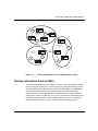
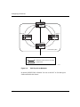
Autonomous Systems .....................................................................................................1-8
Routing Information Protocol (RIP) .................................................................................1-9
Open Shortest Path First (OSPF) Protocol ...................................................................1-10
Border Gateway Protocol (BGP) ...................................................................................1-10
Exterior Gateway Protocol (EGP) .................................................................................1-10
Router Discovery Protocol ............................................................................................1-11
Route Preferences ........................................................................................................1-12
Route Weights ..............................................................................................................1-13
IP Routing Policies and Filters ......................................................................................1-14
IP Traffic Filters .............................................................................................................1-18
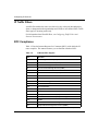
RFC Compliance ..........................................................................................................1-18
303528-A Rev 00
v
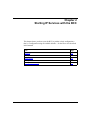
Chapter 2
Starting IP Services with the BCC
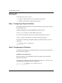
Starting IP .......................................................................................................................2-2
Step 1: Configuring a Physical Interface ..................................................................2-2
Step 2: Configuring an IP Interface ..........................................................................2-2
Starting RIP ....................................................................................................................2-3
Starting OSPF ................................................................................................................2-4
Starting BGP ..................................................................................................................2-5
Step 1: Configuring Global BGP ..............................................................................2-5
Step 2: Defining a Peer-to-Peer Connection ............................................................2-5
Starting Router Discovery ..............................................................................................2-6
Chapter 3
Starting IP Services with Site Manager
Starting IP .......................................................................................................................3-2
Deleting IP from an Interface ...................................................................................3-3
Customizing IP .........................................................................................................3-3
Starting RIP ....................................................................................................................3-4
Adding RIP to an IP Interface ...................................................................................3-5
Deleting RIP from an IP Interface ............................................................................3-6
Customizing RIP ......................................................................................................3-6
Starting OSPF ................................................................................................................3-7
Deleting OSPF from an IP Interface .........................................................................3-8
Customizing OSPF ...................................................................................................3-8
Starting BGP ..................................................................................................................3-9
Deleting BGP from the Router ...............................................................................3-10
Deleting BGP-3 and BGP-4 from the Router .........................................................3-10
Customizing BGP ...................................................................................................3-11
Starting EGP ................................................................................................................3-12
Deleting EGP from the Router ...............................................................................3-13
Customizing EGP ...................................................................................................3-13
Starting NAT .................................................................................................................3-14
Adding NAT to an IP Interface ................................................................................3-14
Deleting NAT from an IP Interface ..........................................................................3-15
vi
303528-A Rev 00
Using the Circuitless IP Interface ..................................................................................3-16
Starting IP on the Circuitless Interface ...................................................................3-17
Choosing Slots to Support the Circuitless Interface ...............................................3-18
Configuring an Unnumbered IP Interface .....................................................................3-19
Using the Alternate Associated Address Option ....................................................3-21
Chapter 4
Configuring and Customizing IP
Customizing IP Global Parameters .................................................................................4-2
Navigating the BCC to the IP Global Prompt ...........................................................4-3
Opening the Site Manager Window for IP Global Parameters .................................4-4
Disabling and Reenabling Global IP ........................................................................4-5
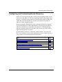
Configuring the Router for Not-Forwarding Mode ....................................................4-6
Configuring Bridging on a Router in Not-Forwarding Mode .....................................4-8
Setting the Time-to-Live Value on a Source Packet ...............................................4-11
Allowing an All-Zero or All-One Subnet Address ...................................................4-13
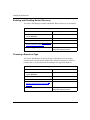
Estimating the Size of the Routing Table ................................................................4-14
Using a Default Route for an Unknown Subnet ......................................................4-15
Specifying the Maximum Number of IP Policies .....................................................4-16
Disabling and Reenabling Route Filter Support .....................................................4-17
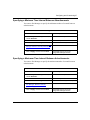
Enabling Equal-Cost Multipath Support .................................................................4-18
Configuring Equal-Cost Multipath for RIP and OSPF ............................................4-20
Enabling and Disabling ECMP Support for IBGP ...................................................4-22
Enabling ISP Mode on the Router ..........................................................................4-22
Customizing the IP Routing Table Structure ..........................................................4-24
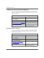
Specifying the Percentage of Buffers Available to ARP .........................................4-25
Customizing an IP Interface ..........................................................................................4-26
Navigating the BCC to an IP Interface Prompt .......................................................4-29
Opening the Site Manager Window for IP Interface Parameters ............................4-30
Configuring a Multinet Interface .............................................................................4-31
Disabling and Reenabling an IP Interface ..............................................................4-32
Specifying a Broadcast Address for an Interface ...................................................4-33
Specifying a Subnet Broadcast Address ................................................................4-35
Specifying the Cost of an Interface ........................................................................4-35
Enabling MTU Discovery on an Interface ...............................................................4-36
Enabling and Disabling ICMP Address-Mask Replies ............................................4-38
303528-A Rev 00
vii
Disabling and Reenabling ICMP Redirect Messages .............................................4-39
Enabling All-Subnet Broadcasting on an Interface .................................................4-41
Disabling UDP Checksum Processing on the Interface .........................................4-42
Specifying a MAC Address or E.164 Address ........................................................4-43
Enabling Source Routing over a Token Ring Network ............................................4-44
Configuring an SMDS Address ..............................................................................4-47
Configuring a WAN Address for a Frame Relay Network .......................................4-48
Specifying the Maximum Size of the Forwarding Table ..........................................4-49
Configuring an Interface for an ATM Logical IP Subnet .........................................4-51
Configuring an Adjacent Host Address .........................................................................4-53
Defining a Static Route .................................................................................................4-56
Defining a Static Default Route ..............................................................................4-60
Defining a Static Black Hole for a Supernet ...........................................................4-60
Configuring and Customizing Router Discovery ...........................................................4-61
Enabling and Disabling Router Discovery ..............................................................4-62
Choosing a Broadcast Type ...................................................................................4-62
Specifying a Minimum Time Interval Between Advertisements .............................4-63
Specifying a Maximum Time Interval Between Advertisements ............................4-63
Configuring the Lifetime of Advertised Addresses .................................................4-64
Specifying Interface Preference .............................................................................4-64
Chapter 5
Configuring Address Resolution
ARP Overview ................................................................................................................5-2
Enabling and Disabling Global ARP ...............................................................................5-4
Customizing Global ARP Characteristics .......................................................................5-5
Selecting an Address Resolution Scheme for an IP Interface ........................................5-6
Selecting an Encapsulation Option for ARP and Probe ..................................................5-8
Enabling Proxy ARP on an Interface ..............................................................................5-9
Timing Out Entries in the Address Resolution Cache ..................................................5-11
viii
303528-A Rev 00
Chapter 6
Customizing RIP Services
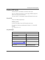
Customizing RIP Global Parameters ..............................................................................6-2
Setting the RIP Diameter .........................................................................................6-2
Customizing a RIP Interface ...........................................................................................6-4
Navigating the BCC to a RIP Interface Prompt ........................................................6-5
Opening the Site Manager Window for RIP Interfaces .............................................6-6
Disabling and Reenabling RIP on an Interface ........................................................6-7
Selecting the RIP Version ........................................................................................6-8
Supplying RIP Updates on an Interface .................................................................6-10
Specifying the Update Mode ..................................................................................6-11
Sending Triggered Updates ....................................................................................6-12
Specifying a Time-to-Live Value .............................................................................6-14
Receiving RIP Updates on an Interface .................................................................6-16
Authenticating the Password on a Version 2 Update ..............................................6-17
Supplying a Default Route on an Interface .............................................................6-19
Listening for a Default Route ..................................................................................6-21
Configuring a RIP Interface for Dial-Optimized Routing .........................................6-22
Setting RIP Timers on an Interface ........................................................................6-22
Specifying an Update Interval ..........................................................................6-22
Specifying a Timeout Period ............................................................................6-24
Specifying a Holddown Period .........................................................................6-26
Specifying a Stabilization Time ........................................................................6-28
Configuring RIP Accept and Announce Policies ...........................................................6-29
Defining a RIP Accept Policy ..................................................................................6-30
Supplying Modification Values for a RIP Accept Policy ..........................................6-33
Specifying Matching Criteria for a RIP Accept Policy .............................................6-35
Defining a RIP Announce Policy ............................................................................6-36
Supplying Modification Values for a RIP Announce Policy .....................................6-39
Specifying Matching Criteria for a RIP Announce Policy ........................................6-40
303528-A Rev 00
ix
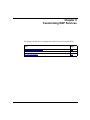
Chapter 7
Customizing OSPF Services
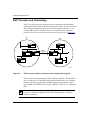
OSPF Concepts and Terminology ..................................................................................7-2
OSPF Addresses and Variable-Length Masks .........................................................7-3
OSPF Neighbors ......................................................................................................7-3
Neighbor Adjacencies ..............................................................................................7-4
Designated Routers .................................................................................................7-4
OSPF Areas .............................................................................................................7-5
OSPF Router Types .................................................................................................7-6
AS External Routes ..................................................................................................7-6
OSPF Implementation Notes ...................................................................................7-7
Customizing OSPF Global Features ...............................................................................7-8
Navigating the BCC to the OSPF Global Prompt .....................................................7-9
Opening the Site Manager Window for OSPF Global Parameters ...........................7-9
Enabling and Disabling OSPF on the Router .........................................................7-10
Supplying an OSPF ID ...........................................................................................7-11
Configuring the Soloist and Backup Soloist on a Slot ............................................7-12
Enabling the Boundary Function ............................................................................7-14
Configuring the Metric Type for an ASE Advertisement .........................................7-15
Choosing a Tag Generation Method for an ASE Advertisement ............................7-18
Setting the Holddown Timer ...................................................................................7-21
Configuring Message Logging ...............................................................................7-22
Configuring External Route Preference .................................................................7-24
Customizing OSPF on an IP Interface ..........................................................................7-25
Navigating the BCC to an OSPF Interface Prompt ................................................7-26
Opening the Site Manager Window for OSPF Interfaces .......................................7-27
Enabling and Disabling OSPF ................................................................................7-28
Configuring an Area ID ..........................................................................................7-29
Specifying the Network Type ..................................................................................7-30
Using Point-to-Multipoint Interfaces in a Star Topology ..........................................7-32
Specifying Router Priority for a Multiaccess Network ............................................7-33
Estimating the Transit Delay ...................................................................................7-35
Setting the Retransmit Interval ...............................................................................7-36
Setting the Hello Interval ........................................................................................7-37
Setting the Dead Interval .......................................................................................7-39
x
303528-A Rev 00
Setting the Poll Interval for NBMA Neighbors ........................................................7-41
Specifying the Metric Cost .....................................................................................7-42
Specifying the MTU Size ........................................................................................7-45
Configuring a Neighbor on an NBMA Interface ......................................................7-47
Defining an Area ...........................................................................................................7-48
Supplying an ID for the Area ..................................................................................7-48
Disabling and Reenabling an Area .........................................................................7-49
Modifying an Area ID ..............................................................................................7-50
Configuring Authentication .....................................................................................7-50
Configuring a Summary Route ...............................................................................7-52
Configuring a Stub Area .........................................................................................7-53
Configuring an Area Border Router ..............................................................................7-55
Configuring a Virtual Backbone Link through a Transit Area ..................................7-56
Configuring OSPF Accept and Announce Policies .......................................................7-59
Defining an OSPF Accept Policy ............................................................................7-60
Supplying Modification Values for an OSPF Accept Policy ....................................7-63
Specifying Matching Criteria for an OSPF Accept Policy .......................................7-65
Defining an OSPF Announce Policy .......................................................................7-67
Supplying Modification Values for an OSPF Announce Policy ...............................7-70
Supplying Matching Criteria for an OSPF Announce Policy ...................................7-72
Chapter 8
Configuring and Customizing BGP
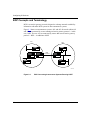
BGP Concepts and Terminology .....................................................................................8-2
Peer-to-Peer Sessions .............................................................................................8-3
Stub and Multihomed Autonomous Systems ...........................................................8-3
Interior BGP Routing ................................................................................................8-4
IBGP Route Reflector ...............................................................................................8-5
BGP Updates ...........................................................................................................8-6
Path Attributes ...................................................................................................8-6
BGP-4 Local Preference Value ..........................................................................8-8
BGP Implementation Notes ......................................................................................8-9
303528-A Rev 00
xi
Configuring BGP Globally .............................................................................................8-10
Enabling and Disabling BGP ..................................................................................8-11
Supplying a BGP Identifier .....................................................................................8-13
Identifying the Local AS .........................................................................................8-14
Disabling and Reenabling IBGP Support ...............................................................8-15
Specifying Route Types for IBGP Advertisements .................................................8-16
Setting the Update Interval Timer ..........................................................................8-18
Allowing Redundant Connections ..........................................................................8-19
Enabling Multihop Connections ..............................................................................8-20
Disabling and Reenabling Dynamic Policy Configuration .......................................8-22
Configuring BGP as a Soloist ................................................................................8-23
Associating a Route Reflector with a Cluster ID ....................................................8-25
Disabling and Reenabling Route Aggregation .......................................................8-25
Enabling and Disabling Black Hole Punching ........................................................8-26
Disabling and Reenabling the BGP-4 MED Attribute .............................................8-27
Establishing a Peer-to-Peer Session ............................................................................8-28
Defining a Peer-to-Peer Session ............................................................................8-29
Initiating a Peer-to-Peer Session ............................................................................8-31
Negotiating the BGP Version .................................................................................8-33
Keeping the Connection Alive ................................................................................8-35
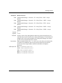
Setting the External Advertisement Timer .............................................................8-37
Specifying a Holddown Time ..................................................................................8-39
Setting a Minimum AS Origination Interval ............................................................8-41
Overriding the Local AS Number ...........................................................................8-43
Specifying a Maximum Update Size ......................................................................8-44
Setting the Route Echo Switch ...............................................................................8-46
Specifying the Route Reflector Mode of the Remote Peer .....................................8-48
Setting the Backoff Timer on an IBGP Route Server .............................................8-49
Using the Circuitless IP Interface for a Peer Session ...................................................8-50
Configuring Peers over an Unnumbered Point-to-Point Link ........................................8-51
Assigning Weight and Class Values to an AS ..............................................................8-53
xii
303528-A Rev 00
Configuring BGP Accept and Announce Policies .........................................................8-55
Defining a BGP Accept Policy ................................................................................8-56
Supplying Modification Values for a BGP Accept Policy ........................................8-59
Specifying Matching Criteria for a BGP Accept Policy ...........................................8-61
Defining a BGP Announce Policy ...........................................................................8-63
Supplying Modification Values for a BGP Announce Policy ...................................8-66
Specifying Matching Criteria for a BGP Announce Policy ......................................8-70
Configuring BGP-4 AS Pattern-Matching ...............................................................8-74
Best-Route Calculation for Equal Routes .....................................................................8-75
OSPF/BGP Interaction .................................................................................................8-75
Configuring BGP Message Logging .............................................................................8-76
Configuring IBGP as a Route Reflector or an RR Client ..............................................8-77
Configuring a Single Route Reflector in an AS ......................................................8-77
Configuring a Route Reflector Cluster ...................................................................8-81
Configuring Multiple RR Clusters in an AS ............................................................8-83
Configuring an RR Client .......................................................................................8-87
Enabling and Disabling IBGP Equal-Cost Multipath .....................................................8-89
Chapter 9
Customizing EGP Services
EGP Concepts and Terminology .....................................................................................9-2
EGP Implementation Notes ......................................................................................9-5
Customizing EGP on the Router ....................................................................................9-6
Enabling and Disabling EGP ....................................................................................9-6
Supplying a Local AS Number .................................................................................9-7
Configuring a Neighbor ...................................................................................................9-8
Specifying the Neighbor’s Address ..........................................................................9-9
Specifying the Gateway Mode ................................................................................9-10
Enabling and Disabling the Neighbor Relationship ................................................9-11
Choosing the Acquisition Mode ..............................................................................9-12
Choosing the Poll Mode .........................................................................................9-13
Setting Neighbor Timers ........................................................................................9-14
303528-A Rev 00
xiii
Chapter 10
Configuring RIPSO on an IP Interface
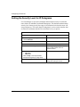
Security Label Format ..................................................................................................10-2
Inbound IP Datagrams ..................................................................................................10-4
Forwarded IP Datagrams ..............................................................................................10-4
Originated IP Datagrams ..............................................................................................10-5
Unlabeled IP Datagrams ..............................................................................................10-5
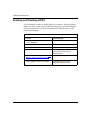
Enabling and Disabling RIPSO .....................................................................................10-6
Specifying the IP Datagram Type for Stripping Security Options ..................................10-7
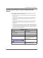
Specifying the Outbound Datagram Type Requiring Security Labels ...........................10-8
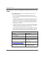
Specifying the Inbound Datagram Type Requiring Security Labels ..............................10-9
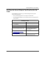
Setting the Security Level for IP Datagrams ...............................................................10-10
Choosing Authority Flags in Outbound Datagrams ....................................................10-11
Choosing Authority Flags in Inbound Datagrams .......................................................10-12
Supplying Implicit Labels for Unlabeled Inbound Datagrams .....................................10-13
Enabling and Disabling Default Labels for Unlabeled Outbound Datagrams ..............10-14
Enabling and Disabling Error Labels for Outbound ICMP Error Datagrams ...............10-15
RIPSO Example .........................................................................................................10-16
Chapter 11
Connecting the Router to a Blacker Front End
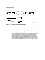
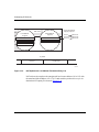
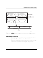
BFE Addressing ............................................................................................................11-3
Configuring Blacker Front-End Support ........................................................................11-4
Chapter 12
Configuring Network Address Translation
Overview of Network Address Translation ....................................................................12-2
Dynamic Address Translation .................................................................................12-2
Static Address Translation ......................................................................................12-7
Customizing NAT Global Attributes ...............................................................................12-8
Enabling and Disabling NAT ...................................................................................12-9
Configuring the Soloist Slot Mask ........................................................................12-10
Configuring the Log Mask ....................................................................................12-11
Enabling and Disabling the Translation Entry Timeout Value ...............................12-13
Configuring the Max Timeout Value .....................................................................12-14
xiv
303528-A Rev 00
Customizing a NAT Interface ......................................................................................12-15
Enabling or Disabling NAT on an Interface ...........................................................12-15
Modifying the Interface Type ................................................................................12-16
Configuring Static Translation .....................................................................................12-17
Adding Static Translation to Local and Global Interfaces .....................................12-17
Enabling and Disabling Static Address Translation ..............................................12-18
Configuring Dynamic Local Address Ranges .............................................................12-19
Adding a Local Address Range ............................................................................12-19
Deleting a Local Address Range ..........................................................................12-20
Enabling or Disabling a Local Address Range .....................................................12-21
Configuring Dynamic Global Address Ranges ...........................................................12-22
Adding a Global Address Range ..........................................................................12-22
Deleting a Global Address Range ........................................................................12-23
Enabling or Disabling a Global Address Range ...................................................12-24
Configuring N-to-1 Address Translation ......................................................................12-25
Chapter 13
Generic Routing Encapsulation Tunnel
GRE Overview ..............................................................................................................13-1
How GRE Tunneling Works ..........................................................................................13-2
Avoiding Tunnel Misconfiguration .................................................................................13-3
Announce Policy .....................................................................................................13-4
Accept Policy ..........................................................................................................13-5
Static Routes ..........................................................................................................13-5
Configuring a Generic Routing Encapsulation Tunnel ..................................................13-6
Adding and Deleting Protocols for GRE Tunnels ..........................................................13-6
Adding a Protocol for a GRE Tunnel ......................................................................13-7
Deleting a Protocol from a GRE Tunnel .................................................................13-7
Configuring a Remote Tunnel End Point .......................................................................13-8
Deleting a Remote Tunnel End Point ..........................................................................13-10
Deleting a GRE Tunnel ...............................................................................................13-11
303528-A Rev 00
xv
Appendix A
Site Manager Parameters
BGP Parameters ............................................................................................................ A-1
BGP Configuration Parameters ............................................................................... A-1
BGP Global Parameters .......................................................................................... A-2
BGP-3 Global Parameters ....................................................................................... A-7
BGP-4 Global Parameters ....................................................................................... A-7
BGP Peer Parameters ............................................................................................. A-7
BGP AS Weight and Weight Class Parameters .................................................... A-14
BGP Event Message Parameters ......................................................................... A-17
EGP Parameters .......................................................................................................... A-18
EGP Global Parameters ........................................................................................ A-18
EGP Neighbor Parameters .................................................................................... A-20
IP Parameters .............................................................................................................. A-23
IP Configuration Parameters ................................................................................. A-23
IP Interface Parameters ........................................................................................ A-25
IP Global Parameters ............................................................................................ A-39
Static Route Parameters ....................................................................................... A-47
Adjacent Host Parameters .................................................................................... A-50
RIPSO Parameters ................................................................................................ A-53
Router Discovery Parameters ............................................................................... A-63
OSPF Parameters ....................................................................................................... A-65
OSPF Global Parameters ...................................................................................... A-65
OSPF Interface Parameters .................................................................................. A-71
Neighbor Parameters for an NBMA Interface ........................................................ A-79
OSPF Area Parameters ........................................................................................ A-80
Area Range Parameters ........................................................................................ A-83
OSPF Virtual Interface Parameters ....................................................................... A-85
RIP Parameters ........................................................................................................... A-88
NAT Parameters ........................................................................................................... A-95
GRE Tunnel Configuration Parameters ...................................................................... A-100
xvi
303528-A Rev 00
Appendix B
Routing Policies
RIP-Specific Accept Policy Parameters ......................................................................... B-7
OSPF-Specific Accept Policy Parameters ..................................................................... B-8
EGP-Specific Accept Policy Parameters ....................................................................... B-9
BGP-3-Specific Accept Policy Parameters .................................................................. B-11
BGP-4-Specific Accept Policy Parameters ............................................................ B-15
IP Announce Policy Parameters .................................................................................. B-20
RIP-Specific Announce Policy Parameters ........................................................... B-38
OSPF-Specific Announce Policy Parameters ........................................................ B-39
EGP-Specific Announce Policy Parameters .......................................................... B-41
BGP-3-Specific Announce Policy Parameters ....................................................... B-43
BGP-4-Specific Announce Policy Parameters ....................................................... B-47
Appendix C
Import and Export Route Filters
RIP Import Filters .......................................................................................................... C-1
RIP Export Filters .......................................................................................................... C-5
OSPF Import Filters ....................................................................................................... C-8
OSPF Export Filters ...................................................................................................... C-9
BGP-3 Import Filters .................................................................................................... C-12
BGP-3 Export Filters ................................................................................................... C-17
EGP Import Filters ....................................................................................................... C-21
EGP Export Filters ....................................................................................................... C-23
Appendix D
Route Weight Worksheet
Appendix E
IP/OSPF Configuration
Index
303528-A Rev 00
xvii
Figures
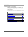
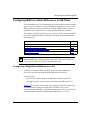
Figure 1-1.
Network and Host Portions of IP Addresses ............................................1-3
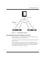
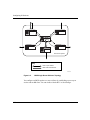
Figure 1-2.
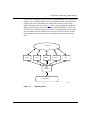
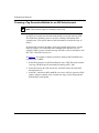
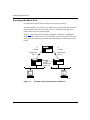
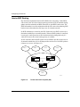
Internet Segmented into Three Autonomous Systems ............................1-9
Figure 1-3.
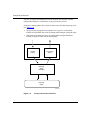
IP Routing Table .....................................................................................1-15
Figure 1-4.
Accept and Announce Policies ...............................................................1-16
Figure 4-1.
IP Interface .............................................................................................4-26
Figure 4-2.
Multinet Configuration ............................................................................4-31
Figure 4-3.
IP Routers Source Routing Across a Token Ring Network ....................4-45
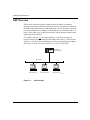
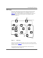
Figure 5-1.
ARP Example ...........................................................................................5-2
Figure 5-2.
Proxy ARP Example ................................................................................5-9
Figure 7-1.
OSPF Areas .............................................................................................7-5
Figure 7-2.
OSPF ASE Routes .................................................................................7-16
Figure 7-3.
AS External Route Tag ...........................................................................7-19
Figure 7-4.
Point-to-Multipoint Topology ...................................................................7-33
Figure 7-5.
Example of Using Configurable Cost Metrics ........................................7-42
Figure 7-6.
Area Border Router ................................................................................7-55
Figure 7-7.
Virtual Link and Transit Area ..................................................................7-57
Figure 8-1.
BGP Connecting Autonomous Systems Running OSPF .........................8-2
Figure 8-2.
Transit Autonomous System (AS) ............................................................8-4
Figure 8-3.
Establishing and Confirming a Connection Between BGP Peers ..........8-31
Figure 8-4.
BGP over an Unnumbered Point-to-Point Link .......................................8-51
Figure 8-5.
IBGP Single Route Reflector Topology ..................................................8-78
Figure 8-6.
BGP Equal-Cost Multipath .....................................................................8-90
Figure 9-1.
EGP Connection Between Two Autonomous Systems Running RIP .......9-2
Figure 10-1. RIPSO Security Label ............................................................................10-2
Figure 10-2. RIPSO Example ...................................................................................10-17
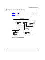
Figure 11-1. Blacker Front-End Network Configuration ..............................................11-2
Figure 12-1. Dynamic Translation Example ................................................................12-4
Figure 12-2. NAT Detects the Unregistered Source Address .....................................12-5
Figure 12-3. NAT Updates the Local/Global Translation Entry List ............................12-6
303528-A Rev 00
xix
Figure 12-4. NAT Replaces the Unregistered Local Address with a Registered Source Address
12-7
Figure 12-5. N-to-1 Address Translation (Local to Global) .......................................12-26
Figure 12-6. N-to-1 Address Translation (Global to Local) .......................................12-27
Figure 13-1. GRE Tunneling .......................................................................................13-3
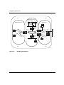
Figure E-1.
xx
IP/OSPF Configuration ........................................................................... E-2
303528-A Rev 00
Tables
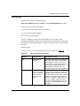
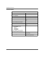
Table 1-1.
Subnet Masks for Class B and Class C Addresses ................................1-6
Table 1-2.
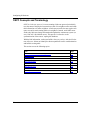
IP Router RFC Support .........................................................................1-18
Table 4-1.
Source Routing Bridge Support for Host-Only Mode
4-8
Table 4-2.
Learning Bridge Support for Host-Only Mode .........................................4-9
Table 4-3.
Mac Address Parameter Settings ..........................................................4-43
Table 4-4.
Adjacent Host BCC Parameters ............................................................4-54
Table 4-5.
BCC Static Route Parameters ..............................................................4-57
Table 6-1.
BCC Definition Parameters for RIP Accept Policies ...............................6-31
Table 6-2.
BCC Override Parameter for RIP Accept Policies ..................................6-33
Table 6-3.
BCC Definition Parameters for RIP Announce Policies .........................6-37
Table 6-4.
BCC Override Parameter for RIP Announce Policies .............................6-39
Table 6-5.
BCC Match Parameters for RIP Announce Policies ...............................6-41
Table 7-1.
OSPF Log Messages ............................................................................7-22
Table 7-2.
Retransmit Interval Settings ...................................................................7-36
Table 7-3.
Hello Interval Settings ............................................................................7-37
Table 7-4.
Dead Interval Settings ............................................................................7-39
Table 7-5.
Cost Settings ..........................................................................................7-43
Table 7-6.
BCC Definition Parameters for OSPF Accept Policies ...........................7-61
Table 7-7.
BCC Matching Parameters for OSPF Accept Policies ...........................7-65
Table 7-8.
BCC Definition Parameters for OSPF Announce Policies ......................7-68
Table 7-9.
BCC Modification Parameters for OSPF Announce Policies .................7-70
Table 7-10.
BCC Matching Parameters for OSPF Announce Policies ......................7-72
Table 8-1.
BGP-3 Path Attributes .............................................................................8-6
Table 8-2.
BGP-4 Optional Path Attributes ..............................................................8-7
Table 8-3.
Route Types for BGP Advertisements ....................................................8-16
Table 8-4.
Slot Mask Parameter Values ..................................................................8-23
Table 8-5.
Black Hole Punching Parameter Settings ..............................................8-26
Table 8-6.
BCC Definition Parameters for BGP Accept Policies .............................8-57
303528-A Rev 00
xxi
xxii
Table 8-7.
BCC Modification Parameters for BGP Accept Policies .........................8-59
Table 8-8.
BCC Matching Parameters for BGP Accept Policies .............................8-61
Table 8-9.
BCC Definition Parameters for BGP Announce Policies ........................8-64
Table 8-10.
BCC Override Parameters for BGP Announce Policies
8-66
Table 8-11.
BCC Match Parameters for BGP Announce Policies .............................8-71
Table 8-12.
Characters in AS Path Pattern-Matching ...............................................8-74
Table 9-1.
Router Mode Determinator ......................................................................9-3
Table 11-1.
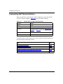
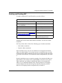
BFE X.25 Packet-Level Parameter Settings ..........................................11-6
Table 11-2.
BFE X.25 Network Service Record Parameter Settings
11-8
Table 12-1.
Default Values for NAT Global Attributes ................................................12-8
Table 12-2.
Log Message Types ............................................................................12-11
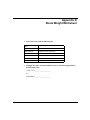
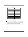
Table E-1.
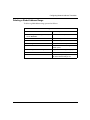
Internal Backbone Router 1 .................................................................... E-3
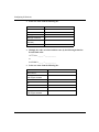
Table E-2.
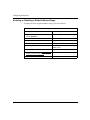
Area Border Router 2 .............................................................................. E-4
Table E-3.
Area Border Router 3 .............................................................................. E-5
Table E-4.
Area Border Router 4 .............................................................................. E-6
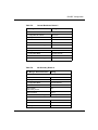
Table E-5.
Internal Backbone Router 5 .................................................................... E-7
Table E-6.
AS Boundary Router 6 ............................................................................ E-7
303528-A Rev 00
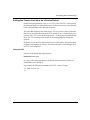
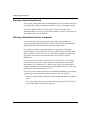
Preface
This guide describes IP services and what you do to start and customize IP
services on a Bay Networks® router.
You can use the Bay Command Console (BCC™) or Site Manager to configure IP
services on a router. In this guide, you will find instructions for using both the
BCC and Site Manager.
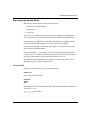
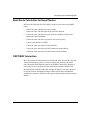
Before You Begin
Before using this guide, you must complete the following procedures. For a new
router:
•
Install the router (see the installation manual that came with your router).
•
Connect the router to the network and create a pilot configuration file (see
Quick-Starting Routers, Configuring BayStack Remote Access, or Connecting
ASN Routers to a Network).
Make sure that you are running the latest version of Bay Networks BayRS™ and
Site Manager software. For information about upgrading BayRS and Site
Manager, see the upgrading guide for your version of BayRS.
303528-A Rev 00
xxiii
Configuring IP Services
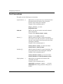
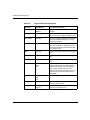
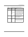
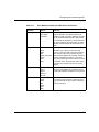
Text Conventions
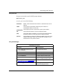
This guide uses the following text conventions:
angle brackets (< >)
Indicate that you choose the text to enter based on the
description inside the brackets. Do not type the
brackets when entering the command.
Example: If the command syntax is:
ping <ip_address>, you enter:
ping 192.32.10.12
bold text
Indicates text that you need to enter and command
names and options.
Example: Enter show ip {alerts | routes}
Example: Use the dinfo command.
braces ({})
Indicate required elements in syntax descriptions
where there is more than one option. You must choose
only one of the options. Do not type the braces when
entering the command.
Example: If the command syntax is:
show ip {alerts | routes}, you must enter either:
show ip alerts or show ip routes.
brackets ([ ])
Indicate optional elements in syntax descriptions. Do
not type the brackets when entering the command.
Example: If the command syntax is:
show ip interfaces [-alerts], you can enter either:
show ip interfaces or show ip interfaces -alerts.
ellipsis points (. . . )
Indicate that you repeat the last element of the
command as needed.
Example: If the command syntax is:
ethernet/2/1 [<parameter> <value>] . . ., you enter
ethernet/2/1 and as many parameter-value pairs as
needed.
xxiv
303528-A Rev 00
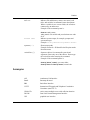
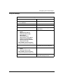
Preface
italic text
Indicates file and directory names, new terms, book
titles, and variables in command syntax descriptions.
Where a variable is two or more words, the words are
connected by an underscore.
Example: If the command syntax is:
show at <valid_route>
valid_route is one variable and you substitute one value
for it.
screen text
Indicates system output, for example, prompts and
system messages.
Example: Set Bay Networks Trap Monitor Filters
separator ( > )
Shows menu paths.
Example: Protocols > IP identifies the IP option on the
Protocols menu.
vertical line ( | )
Separates choices for command keywords and
arguments. Enter only one of the choices. Do not type
the vertical line when entering the command.
Example: If the command syntax is:
show ip {alerts | routes}, you enter either:
show ip alerts or show ip routes, but not both.
Acronyms
303528-A Rev 00
AUI
Attachment Unit Interface
BootP
Bootstrap Protocol
BRI
Basic Rate Interface
CCITT
International Telegraph and Telephone Consultative
Committee (now ITU-T)
CSMA/CD
carrier sense multiple access with collision detection
DLCMI
Data Link Control Management Interface
GUI
graphical user interface
xxv
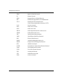
Configuring IP Services
xxvi
HDLC
high-level data link control
IP
Internet Protocol
ISDN
Integrated Services Digital Network
ISO
International Organization for Standardization
ITU-T
International Telecommunications
Union-Telecommunications (formerly CCITT)
LAN
local area network
MAC
media access control
MAU
media access unit
MDI-X
media-dependent interface with crossover
NBMA
nonbroadcast multi-access
OSI
Open Systems Interconnection
OSPF
Open Shortest Path First (Protocol)
PPP
Point-to-Point Protocol
SMDS
switched multimegabit data service
SNMP
Simple Network Management Protocol
STP
shielded twisted-pair
TCP/IP
Transmission Control Protocol/Internet Protocol
Telnet
Telecommunication Network
TFTP
Trivial File Transfer Protocol
TPE
twisted-pair Ethernet
UTP
unshielded twisted-pair
WAN
wide area network
303528-A Rev 00
Preface
Bay Networks Technical Publications
You can now print Bay Networks technical manuals and release notes free,
directly from the Internet. Go to support.baynetworks.com/library/tpubs/. Find the
Bay Networks product for which you need documentation. Then locate the
specific category and model or version for your hardware or software product.
Using Adobe Acrobat Reader, you can open the manuals and release notes, search
for the sections you need, and print them on most standard printers. You can
download Acrobat Reader free from the Adobe Systems Web site,
www.adobe.com.
You can purchase Bay Networks documentation sets, CDs, and selected technical
publications through the Bay Networks Collateral Catalog. The catalog is located
on the World Wide Web at support.baynetworks.com/catalog.html and is divided
into sections arranged alphabetically:
•
The “CD ROMs” section lists available CDs.
•
The “Guides/Books” section lists books on technical topics.
•
The “Technical Manuals” section lists available printed documentation sets.
Make a note of the part numbers and prices of the items that you want to order.
Use the “Marketing Collateral Catalog description” link to place an order and to
print the order form.
How to Get Help
For product assistance, support contracts, or information about educational
services, go to the following URL:
http://www.baynetworks.com/corporate/contacts/
Or telephone the Bay Networks Technical Solutions Center at:
800-2LANWAN
303528-A Rev 00
xxvii
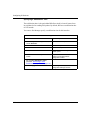
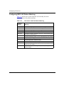
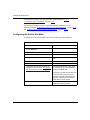
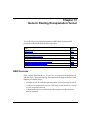
Chapter 1
IP Concepts, Terminology, and Features
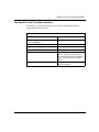
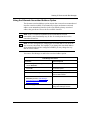
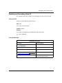
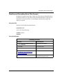
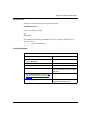
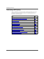
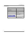
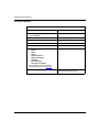
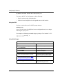
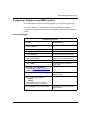
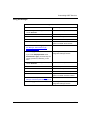
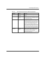
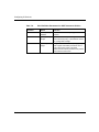
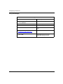
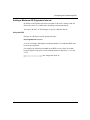
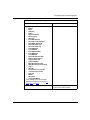
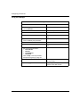
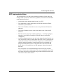
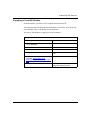
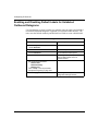
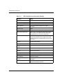
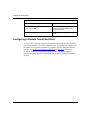
The following topics introduce concepts and terminology used in this manual:
303528-A Rev 00
Topic
Page
IP Addresses
1-2
Autonomous Systems
1-8
Routing Information Protocol (RIP)
1-9
Open Shortest Path First (OSPF) Protocol
1-10
Border Gateway Protocol (BGP)
1-10
Exterior Gateway Protocol (EGP)
1-10
Router Discovery Protocol
1-11
Route Preferences
1-12
Route Weights
1-13
IP Routing Policies and Filters
1-14
IP Traffic Filters
1-18
RFC Compliance
1-18
1-1
Configuring IP Services
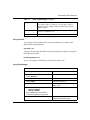
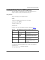
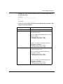
IP Addresses
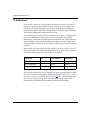
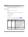
An IP address consists of 32 bits that have the form network.host. The network
portion is a network number ranging from 8 to 24 bits. The host portion is the
remaining 8 to 24 bits identifying a specific host on the network. The Internet
Network Information Center (NIC) assigns the network portion of the IP address.
Your network administrator assigns the host portion.
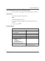
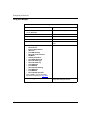
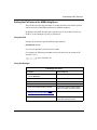
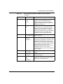
NIC recognizes three primary classes of networks: A, B, and C. In addition, NIC
has recently identified two other classes: Class D for networks that support
multicasting, which allows an IP datagram to be transmitted to a single multicast
group consisting of hosts spread across separate physical networks; and Class E
for experimental networks. The IP router does not fully support Class D or Class E
networks.
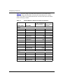
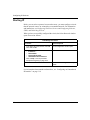
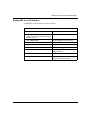
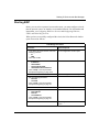
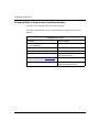
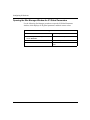
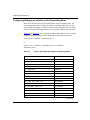
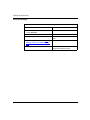
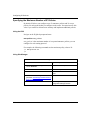
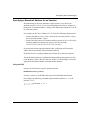
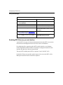
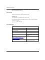
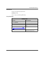
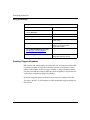
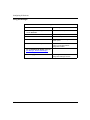
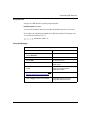
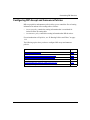
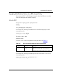
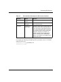
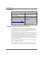
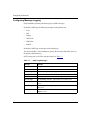
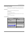
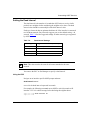
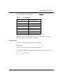
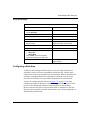
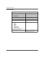
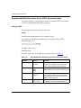
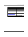
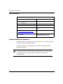
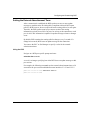
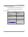
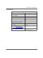
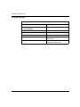
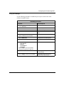
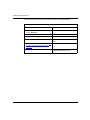
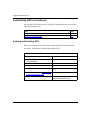
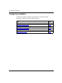
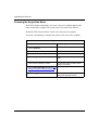
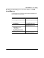
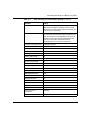
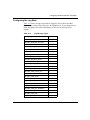
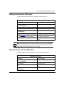
Based on the size of the network, the NIC classifies a network as Class A, B, or C
(the most common). The network class determines the number of bits assigned to
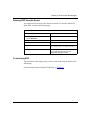
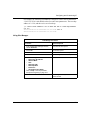
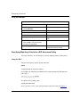
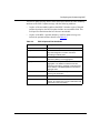
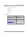
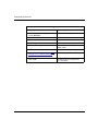
the network and host portions of the IP address, as follows:
Network Size
Class
Network Portion
Host Portion
More than 65,534 hosts
A
8 bits
24 bits
254 to 65,533 hosts
B
16 bits
16 bits
Fewer than 254 hosts
C
24 bits
8 bits
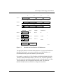
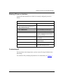
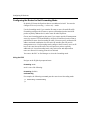
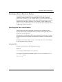
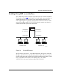
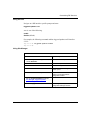
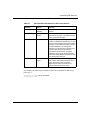
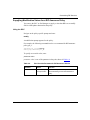
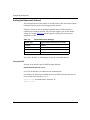
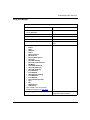
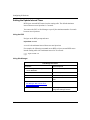
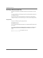
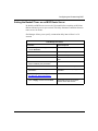
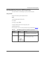
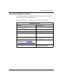
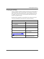
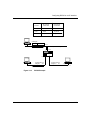
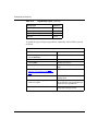
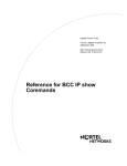
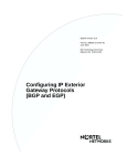
The position of the first bit set to 0 (whether it is the first, second, third, or fourth
bit) in the first octet of an IP address indicates the network Class (A, B, C, or D).
If no bit is set to 0, it is a Class E network. Figure 1-1 shows the placement of the
first bit set to 0 for Class A, B, and C networks. The figure also shows how a
network’s class affects the network and host portions of the IP address.
1-2
303528-A Rev 00
IP Concepts, Terminology, and Features
Class A
Class B
Class C
8
16
24
31
8
16
24
31
8
16
24
31
0
1 0
1 1 0
First Octet
Range
Example
Network Host
Class A
11
1-127
25.0.0.1
25
1
Class B
1 0
128-191
140.250.0.1
140.250
1
Class C
1 1 0
192-223
192.2.3.1
192.2.3
1
Network portion
Host portion
IP0005A
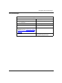
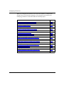
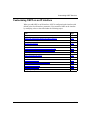
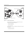
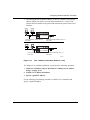
Figure 1-1.
Network and Host Portions of IP Addresses
You specify IP addresses in dotted-decimal notation. To express an IP address in
dotted-decimal notation, you convert each 8-bit octet of the IP address to a
decimal number and separate the numbers by decimal points.
For example, you specify the 32-bit IP address 10000000 00100000 00001010
10100111 in dotted-decimal notation as 128.32.10.167. The most significant 2
bits (10) in the first octet indicate that the network is Class B; therefore, the first
16 bits compose the NIC-assigned network portion field. The third octet
(00001010) and fourth octet (10100111) compose the host field.
303528-A Rev 00
1-3
Configuring IP Services
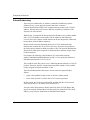
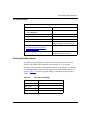
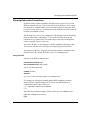
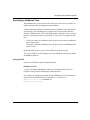
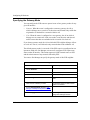
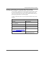
Subnet Addressing
The concept of subnetworks (or subnets) extends the IP addressing scheme.
Subnets are two or more physical networks that share a common
network-identification field (the NIC-assigned network portion of the 32-bit IP
address). Subnets allow an IP router to hide the complexity of multiple LANs
from the rest of the internet.
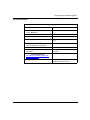
With subnets, you partition the host portion of an IP address into a subnet number
and a “real” host number on that subnet. The IP address is then defined by
network.subnet.host. Routers outside the network do not interpret the subnet and
host portions of the IP address separately.
Routers inside a network containing subnets use a 32-bit subnet mask that
identifies the extension bits. In network.subnet.host, the subnet.host portion (or
the local portion) contains an arbitrary number of bits. The network administrator
allocates bits within the local portion to subnet and host, and then assigns values
to subnet and host.
For example, the following is the IP address of a network that contains
subnets: 10000000 00100000 00001010 10100111. You specify this address in
dotted-decimal notation as 128.32.10.167.
The second bit of the first octet is set to 0, indicating that the network is a Class B
network. Therefore, the NIC-assigned network portion contains 16 bits, and the
locally assigned local portion contains 16 bits.
The network administrator allocates the 16 bits in the local portion field as
follows:
•
Upper 8 bits (00001010) with a value of 10 to the subnet portion
•
Lower 8 bits (10100111) with a value of 167 to the host portion
In other words, the 16-bit local portion field, together with the 16-bit network
field, specify host 167 on subnet 10 of network 128.32.
You now need a subnet mask to identify those bits in the 32-bit IP address that
specify the network field and those bits that specify the subnet field. Like the IP
address, you specify the subnet mask in dotted-decimal notation.
1-4
303528-A Rev 00
IP Concepts, Terminology, and Features
You construct a subnet mask as follows:
•
Assign a value of 1 to each of the 8, 16, or 24 bits in the network field.
•
Assign a value of 1 to each bit in the subnet field.
•
Assign a value of 0 to each bit in the host field.
•
Convert the resulting 32-bit string to dotted-decimal notation.
For example, to construct a subnet mask for the IP address described earlier
(10000000 00100000 00001010 10100111), do the following:
1. Assign a value of 1 to each bit in the network field.
The position of the first bit set to 0 in the first octet of the IP address indicates
that the network is Class B; therefore, the network field contains 16 bits:
11111111 11111111.
2. Assign a value of 1 to each bit in the subnet field.
The network administrator allocated the upper 8 bits of the local portion to the
subnet portion, as follows: 11111111.
3. Assign a value of 0 to each bit in the host field.
The network administrator allocated the lower 8 bits of the local portion field
to the host identification, as follows: 00000000.
4. Convert the resulting 32-bit string (11111111 11111111 11111111 00000000)
to dotted-decimal notation, as follows: 255.255.255.000.
303528-A Rev 00
1-5
Configuring IP Services
Table 1-1 shows the range of possible subnet masks for Class B and Class C
addresses, along with the number of bits that the mask allocates for a subnet
address, the number of recommended subnets associated with the mask, and the
number of hosts per subnet.
Table 1-1.
Subnet Masks for Class B and Class C Addresses
Subnet Mask
Number of Subnets
Number of Hosts
(Recommended)
per Subnet
2
255.255.192.0
2
16,382
3
255.255.224.0
6
8,190
4
255.255.240.0
14
4,094
5
255.255.248.0
30
2,046
6
255.255.252.0
62
1,022
7
255.255.254.0
126
510
8
255.255.255.0
254
254
9
255.255.255.128
510
126
10
255.255.255.192
1,022
62
11
255.255.255.224
2,046
30
12
255.255.255.240
4,094
14
13
255.255.255.248
8,190
6
14
255.255.255.252
16,382
2
2
255.255.255.192
2
62
3
255.255.255.224
6
30
4
255.255.255.240
14
14
5
255.255.255.248
30
6
6
255.255.255.252
62
2
Number of Bits
Class B
Class C
1-6
303528-A Rev 00
IP Concepts, Terminology, and Features
Supernet Addressing
A supernet is a group of networks identified by contiguous network addresses. IP
service providers can assign customers blocks of contiguous addresses to define
supernets as needed.
Each supernet has a unique supernet address that consists of the upper bits shared
by all of the addresses in the contiguous block. For example, consider the
following block of contiguous 32-bit addresses (192.32.0.0 to 192.32.7.0 in
dotted-decimal notation).
11000000
11000000
11000000
11000000
11000000
11000000
11000000
11000000
00100000
00100000
00100000
00100000
00100000
00100000
00100000
00100000
00000000
00000001
00000010
00000011
00000100
00000101
00000110
00000111
00000000
00000000
00000000
00000000
00000000
00000000
00000000
00000000
IP0007A
The supernet address for this block is 11000000 00100000 00000, the 21 upper
bits shared by the 32-bit addresses.
A complete supernet address consists of an address/mask pair:
•
address is the first 32-bit IP address in the contiguous block. In this example,
the address is 11000000 00100000 00000000 00000000 (192.32.0.0 in
dotted-decimal notation).
•
mask is a 32-bit string containing a set bit for each bit position in the supernet
part of the address. The mask for the supernet address in this example is
11111111 11111111 11111000 00000000 (255.255.248.0 in dotted-decimal
notation).
The complete supernet address in this example is 192.32.0.0/255.255.248.0.
303528-A Rev 00
1-7
Configuring IP Services
Classless Interdomain Routing
Classless interdomain routing (CIDR) is an addressing scheme that employs
supernet addresses to represent multiple IP destinations. Rather than advertise a
separate route for each destination in a supernet, a router can use a supernet
address to advertise a single route -- called an aggregate route -- that represents all
of the destinations. This reduces the size of the routing tables used to store
advertised IP routes.
BGP-4 supports classless interdomain routing. OSPF supports classless routing
within a domain.
Autonomous Systems
LANs and WANs interconnected by IP routers form a group of networks called an
internet. For administrative purposes, an internet is divided into autonomous
systems. An autonomous system (AS) is simply a collection of routers (called
gateways in IP terminology) and hosts. Figure 1-2 depicts a sample internet
segmented into three autonomous systems.
1-8
303528-A Rev 00
IP Concepts, Terminology, and Features
Router
2
LAN
A
LAN
B
Autonomous
system 2
Router
1
Router
4
Router
3
LAN
C
Router
5
Autonomous
system 3
Router
8
Autonomous
system 1
Router
7
LAN
G
LAN
F
Router
9
LAN
D
Router
6
LAN
E
IP0006A
Figure 1-2.
Internet Segmented into Three Autonomous Systems
Routing Information Protocol (RIP)
The Routing Information Protocol (RIP) is a distance-vector protocol that enables
routers in the same autonomous system to exchange routing information by means
of periodic RIP updates. Routers transmit their own RIP updates to neighboring
networks and listen for RIP updates from the routers on those neighboring
networks. Routers use the information in the RIP updates to keep their internal
routing tables current. For RIP, the “best” path to a destination is the shortest path
(the path with the fewest hops). RIP computes distance as a metric, usually the
number of hops (or routers) from the origin network to the target network.
303528-A Rev 00
1-9
Configuring IP Services
Open Shortest Path First (OSPF) Protocol
The Open Shortest Path First (OSPF) protocol is an interior gateway protocol
(IGP) intended for use in large networks. Using a link state algorithm, OSPF
exchanges routing information between routers in an autonomous system. Routers
synchronize their topological databases. Once the routers are synchronized and
the routing tables are built, the routers will flood topology information only in
response to some topological change. For OSPF, the “best” path to a destination is
the path that offers the least cost metric delay. In OSPF, cost metrics are
configurable, allowing you to specify preferred paths.
OSPF supports CIDR and can carry supernet advertisements within a routing
domain.
Border Gateway Protocol (BGP)
The Border Gateway Protocol (BGP) is an exterior gateway protocol used to
exchange network reachability information with other BGP systems. BGP routers
form relationships with other BGP routers. Using an entity called a BGP speaker,
BGP routers transmit and receive current routing information over a reliable
transport layer connection. Because a reliable transport mechanism is used,
periodic updates are not necessary.
BGP updates contain “path attributes” that describe the route to a set of
destination networks. When multiple paths are available, BGP compares these
path attributes to choose the preferred path.
BGP-3 and BGP-4 are supported. BGP-4 is the border gateway protocol that
supports CIDR.
Exterior Gateway Protocol (EGP)
The Exterior Gateway Protocol (EGP-2) is used to exchange network reachability
information between routers in different autonomous systems. An IGP, such as
RIP or OSPF, is used within an AS to facilitate the communication of routing
information within the autonomous system. The routers that serve as the end
points of a connection between two autonomous systems run an exterior gateway
protocol, such as EGP-2.
1-10
303528-A Rev 00
IP Concepts, Terminology, and Features
Routers establish EGP neighbor relationships in order to periodically exchange
reliable network reachability information. The router uses this information to
maintain a list of gateways, the networks the gateways can reach, and the
corresponding distances.
Router Discovery Protocol
Before a host can send IP datagrams beyond its directly attached subnet, the host
must discover the address of at least one operational router on that subnet. Router
Discovery is an extension of the Internet Control Message Protocol (ICMP) that
enables hosts attached to multicast or broadcast networks to discover the IP
addresses of their neighboring routers.
Routers configured with Router Discovery periodically multicast or broadcast a
router advertisement from each of their interfaces, announcing the IP address or
addresses of that interface. Hosts discover the addresses of their neighboring
routers by listening for these advertisements. Hosts will use the router with the
highest preference level as a gateway.
303528-A Rev 00
1-11
Configuring IP Services
Route Preferences
The IP router maintains an internal routing table. When determining how to
forward a datagram, the IP router consults the table to determine the specific route
a datagram should take. A routing table can contain direct routes for the IP
router’s network interfaces, static routes, and the routes learned from RIP, OSPF,
BGP, and/or EGP, if enabled (information about adjacent hosts is maintained in a
separate table).
A routing table can contain multiple routes to the same destination. In such a
situation, IP uses (among other information) a preference value to determine
which route to select. Preference values range from 1 to 16 (the higher the
number, the greater the preference).
By default, RIP, BGP, EGP, and OSPF external routes have a preference value of
1. Static routes, direct routes, and OSPF intra-area and interarea routes have a
default preference of 16.
You can configure a preference value in the range of 1 to 16 for RIP, BGP, EGP,
OSFP external, and static routes. You cannot configure the preference of direct
routes and OSPF intra-area and interarea routes.
To assign a preference to a route learned by RIP, OSPF, BGP, and EGP, you
configure an accept policy for the route. If an incoming route matches the policy,
IP assigns the preference value you specify to the route and considers the route for
possible inclusion in the routing table.
1-12
303528-A Rev 00
IP Concepts, Terminology, and Features
Route Weights
Route-weight calculation is an internal tool that IP uses to facilitate selection of
the best route among alternative routes to the same destination. Route-selection
criteria are encoded into the route weight in a way that allows IP to compare
routes simply by comparing their weight values, regardless of route sources.
Appendix D contains a worksheet that you can you use to calculate route weights
in your configuration.
Route-weight calculation increases the efficiency of the route-selection process.
It also reduces the size of the routing database because all route selection
parameters for each route are encoded in a single integer -- the weight value -rather than stored in separate variables.
Using selection criteria encoded in the route weight, IP chooses routes in the
following order:
1. The route with the highest preference value (see “Route Preferences” on
page 1-12)
2. A direct or OSPF intra-area route with the lowest metric
3. A direct route with the lowest metric
4. An OSPF intra-area route with the lowest metric
5. An OSPF interarea route with the lowest metric
6. An OSPF Type 1 external route with the lowest metric
7. A BGP route with the highest LOCAL_PREF value
8. A RIP route with the lowest metric
9. An EGP route with the lowest metric
10. A static route with the lowest metric
11. An OSPF Type 2 external route with a metric type earlier than Router
Software Version 8.00
Note: If OSPF is configured to propagate external routes using the route
weight as the type 2 metric, routes that are received as OSPF ASE type 2
routes are evaluated according to their respective origins (for example, RIP or
BGP).
303528-A Rev 00
1-13
Configuring IP Services
IP Routing Policies and Filters
The IP router allows you to control the flow of routing data to and from the
routing tables. This control is provided by two mechanisms:
•
IP accept and announce policies
•
IP import and export filters
Note: Accept and announce policies provide a superset of the parameters
provided by import and export filters. Bay Networks supports both IP policies
and IP route filters. However, network administrators using import and export
filters for routing table management should migrate as quickly as possible to
IP policies.
IP accept policies (and the subset of parameters provided by import filters) govern
the addition of new RIP-, OSPF-, BGP-, or EGP-derived routes to the routing
tables. When RIP, OSPF, BGP, or EGP receives a new routing update, it consults
its accept policies to validate the information before entering the update into the
routing tables. Accept policies contain search information (to match fields in
incoming routing updates) and action information (to specify the action to take
with matching routes).
IP announce policies (and the subset of parameters provided by export filters)
govern the propagation of RIP, OSPF, BGP, or EGP routing information. When
preparing a routing advertisement, RIP, OSPF, BGP, or EGP consults its announce
policies to determine whether the routes to specific networks are to be advertised
and how they are to be propagated. Announce policies contain network numbers
(to associate a policy with a specific network) and action information (to specify a
route propagation procedure).
1-14
303528-A Rev 00
IP Concepts, Terminology, and Features
Every IP router maintains a table of current routing information. The routing table
manager receives routing updates from the network through the Internet protocols
running on the router. Periodically, the routing table manager issues routing
updates through the protocols. Figure 1-3 shows a router configured with all of the
Internet protocols supported by Bay Networks: OSPF, RIP, BGP-3, BGP-4, and
EGP. The arrows indicate the direction of flow of routing information between the
network and the protocols running on the router, between the protocols and the
routing table manager, and between the routing table manager and the routing
table.
IP network
OSPF
RIP
BGP-3
BGP-4
EGP
Routing
table
manager
Routing table
IP0035A
Figure 1-3.
303528-A Rev 00
IP Routing Table
1-15
Configuring IP Services
The flow of routing information between the network, the protocols, and the
routing table manager is controlled by routing information policies.
Each time a routing update arrives from a remote router, the following steps occur
(see Figure 1-4):
1. The protocol receiving the route consults an accept policy to determine
whether to forward the route to the IP routing table manager or drop the route.
2. If the protocol forwards the route, the routing table manager determines
whether to inject the route into the routing table.
Accept
policy
Announce
policy
Routing
table
manager
Routing
table
IP0036A
Figure 1-4.
1-16
Accept and Announce Policies
303528-A Rev 00
IP Concepts, Terminology, and Features
Periodically, the routing table manager announces routes to other routers in the
network as follows:
1. The routing table manager forwards a route for advertisement to the protocol.
2. The protocol consults an announce policy to determine whether or not to
advertise the route to the network.
Note: The way OSPF applies accept and announce policies to routing
information differs in several ways from the procedure shown in Figure 1-4.
OSPF link-state advertisements (LSAs) are received and placed in the link
state database (LSDB) of the router. The information in the LSDB is also
propagated to other routers in the OSPF routing domain. According to the
OSPF standard, all routers in a given area must maintain a similar database. To
maintain database integrity across the network, a router must not manipulate
received LSAs before propagating them to other routers. To accomplish this,
OSPF accept and announce policies act in the following manner:
OSPF accept policies control which OSPF non-self-originated external routing
information is passed to the routing table manager. The accept policies control
only what the local router uses; they do not affect the propagation of OSPF
internal and OSPF non-self-originated external information to other routers.
OSPF announce policies control which self-originated external routing updates
are placed into the LSDB for distribution according to the OSPF standard.
OSPF announce policies affect what other routers learn but only with regard to
the local router’s self-originated information.
IP accept and announce policies and policy parameters are described in
Appendix B.
IP import and export filters and filter parameters are described in Appendix C.
303528-A Rev 00
1-17
Configuring IP Services
IP Traffic Filters
A traffic filter enables the router to selectively relay or drop an inbound packet,
frame, or datagram based on standard protocol fields or user-defined fields. Traffic
filters apply to incoming traffic only.
For information about IP traffic filters, see Configuring Traffic Filters and
Protocol Prioritization.
RFC Compliance
Table 1-2 lists the Internet Requests for Comments (RFCs) with which the IP
router complies. This manual assumes you are familiar with these RFCs.
Table 1-2.
IP Router RFC Support
RFC
Specifies
768
User Datagram Protocol (UDP)
783
Trivial File Transfer Protocol (TFTP)
791
Internet Protocol (IP)
792
Internet Control Message Protocol (ICMP)
793 and 1323
Transmission Control Protocol
826
Address Resolution Protocol (ARP)
903
RARP server
904
EGP-2
950
Internet subnetting procedures
951
BootP
1009
Internet gateways
1027
Proxy ARP
1042
IP over IEEE 802.x networks
1058 and 1388
Routing Information Protocol (RIP)
1063
Maximum transmission unit (MTU) discovery option
1108
RIPSO
1112
Host extensions for IP multicasting
1157
Simple Network Management Protocol (SNMP)
(continued)
1-18
303528-A Rev 00
IP Concepts, Terminology, and Features
Table 1-2.
303528-A Rev 00
IP Router RFC Support (continued)
RFC
Specifies
1188
IP over FDDI networks
1209
IP over SDMS
1256
ICMP Router Discovery messages
1267
BGP-3
1293
Inverse ARP over frame relay
1332
IP over PPP
1356
IP over X.25
1403
BGP OSPF Interaction
1483
IP over ATM DXI, IP over PVC, IP multicast over PVC
1490
IP over frame relay
1577
IP over SVC
1583
Open Shortest Path First (OSPF) Protocol Version 2
1771
BGP-4
1-19
Chapter 2
Starting IP Services with the BCC
This chapter shows you how to use the BCC to perform a basic configuration -that is, a configuration using all available defaults -- for the IP services described
in this manual.
303528-A Rev 00
Topic
Page
Starting IP
2-2
Starting RIP
2-3
Starting OSPF
2-4
Starting BGP
2-5
Starting Router Discovery
2-6
2-1
Configuring IP Services
Starting IP
To start IP on the router, you must:
1. Configure a physical interface on an available slot/connector.
2. Configure an IP interface on the physical interface.
Step 1: Configuring a Physical Interface
To configure a physical interface on a slot and connector, navigate to the top-level
box prompt and enter:
interface_type slot slot_number connector connector_number
interface_type is the name of a link module on the router.
slot_number is the number of the slot on which the link module is located.
connector_number is the number of a connector on the link module.
For example, the following command configures an Ethernet interface on slot 2,
connector 2:
box# ethernet slot 2 connector 2
ethernet/2/2#
Step 2: Configuring an IP Interface
To configure an IP interface on a physical interface, navigate to the prompt for the
physical interface and enter:
ip address address mask mask
address and mask are a valid IP address and its associated mask, expressed in
dotted-decimal notation.
For example, the following command configures IP interface 2.2.2.2/255.0.0.0 on
an Ethernet physical interface on slot 2, connector 2:
ethernet/2/2# ip address 2.2.2.2 mask 255.0.0.0
ip/2.2.2.2/255.0.0.0#
2-2
303528-A Rev 00
Starting IP Services with the BCC
An IP interface is now configured on the Ethernet interface with default values for
all interface parameters. When you configure an IP interface, the BCC also
configures IP globally on the router with default values for all IP global
parameters.
You customize IP by modifying IP global and interface parameters as described in
Chapter 4.
Starting RIP
You start RIP on the router by adding RIP to an existing IP interface.
Navigate to an IP interface-specific prompt and enter:
rip
For example, the following command adds RIP to IP interface 2.2.2.2255.0.0.0:
ip/2.2.2.2/255.0.0.0# rip
rip/2.2.2.2#
RIP is now running on the router and on the interface with default values for all
parameters. You customize RIP by modifying RIP parameters as described in
Chapter 6.
303528-A Rev 00
2-3
Configuring IP Services
Starting OSPF
You start OSPF on the router by adding OSPF to an existing IP interface.
Navigate to an IP interface-specific prompt and enter:
ospf area area_id
area_id is the identifier, expressed in dotted-decimal notation, of the OSPF area to
which the router is connected through the IP interface.
For example, the following command adds OSPF to IP interface 2.3.3.3/255.0.0.0.
This interface connects the router to OSPF area 0.0.0.0, the OSPF backbone.
ip/2.3.3.3/255.0.0.0# ospf area 0.0.0.0
ospf/2.3.3.3#
OSPF is now running on the router and on the interface with default values for all
interface parameters. You customize OSPF on the interface by modifying
interface parameters as described in Chapter 7.
When you add OSPF to an IP interface, the BCC automatically starts OSPF on the
router with default values for all global parameters. You customize global IP by
modifying OSPF parameters as described in Chapter 7.
2-4
303528-A Rev 00
Starting IP Services with the BCC
Starting BGP
To start BGP:
1. Configure BGP on the router.
2. Define a BGP peer-to-peer connection.
Step 1: Configuring Global BGP
To configure BGP on the router, navigate to the global IP prompt and enter:
bgp
BGP is now running on the router with default values for all BGP parameters. You
customize BGP by modifying BGP parameters as described in Chapter 8.
Step 2: Defining a Peer-to-Peer Connection
BGP exchanges routing information with BGP peers located in another
autonomous system (AS) or within the same AS.
To define a peer-to-peer connection, navigate to the BGP prompt and enter:
peer local local_ip_address remote remote_ip_address as as_number
local_ip_address is the address, expressed in dotted-decimal format, of an IP
interface on the local router.
remote_ip_address is the address of an IP interface on the remote peer’s router.
as_number is the number of the AS in which the remote peer is located.
For example, the following command defines a peer-to-peer connection between
local IP interface 2.3.3.3 and remote interface 2.3.3.4. The remote BGP peer is
located in AS 4.
bgp# peer local 2.3.3.3 remote 2.3.3.4 as 4
peer/2.3.3.3/2.3.3.4#
The BGP peer-to-peer relationship is now established with default values for all
BGP peer parameters. You customize the peer-to-peer connection by modifying
BGP peer parameters as described in Chapter 8.
303528-A Rev 00
2-5
Configuring IP Services
Starting Router Discovery
You start Router Discovery by adding it to an IP interface.
Navigate to an IP interface-specific prompt and enter:
rdisc
The Router Discovery prompt appears.
For example, the following command adds Router Discovery to IP interface
2.2.2.2/255.0.0.0:
ip/2.2.2.2/255.0.0.0# rdisc
rdisc/2.2.2.2#
Router Discovery is now running on IP interface 2.2.2.2/255.0.0.0 with default
values for all parameters. You customize Router Discovery on the interface by
modifying parameters as described in “Configuring and Customizing Router
Discovery” on page 4-61.
2-6
303528-A Rev 00
Chapter 3
Starting IP Services with Site Manager
This chapter shows you how to use Site Manager to perform a basic configuration
-- that is, a configuration using all available defaults -- for the IP services
described in this manual.
303528-A Rev 00
Topic
Page
Starting IP
3-2
Starting RIP
3-4
Starting OSPF
3-7
Starting BGP
3-9
Starting EGP
3-12
Starting NAT
3-14
Using the Circuitless IP Interface
3-16
Configuring an Unnumbered IP Interface
3-19
3-1
Configuring IP Services
Starting IP
Before you can select a protocol to run on the router, you must configure a circuit
that the protocol can use as an interface to an attached network. For information
and instructions, see Configuring WAN Line Services and Configuring Ethernet,
FDDI, and Token Ring Services.
When you have successfully configured the circuit, the Select Protocols window
opens. Proceed as follows:
Site Manager Procedure
You do this
System responds
1. In the Select Protocols window, select IP.
Then click on OK.
The IP Configuration window opens.
2. Set the following parameters:
• IP Address
• Subnet Mask
• Transmit Bcast Addr
• UnNumbered Assoc Address
Click on Help or see the parameter
descriptions beginning on page A-23.
3. Click on OK.
You return to the Configuration Manager
window.
For information about unnumbered interfaces, see “Configuring an Unnumbered
IP Interface” on page 3-19.
3-2
303528-A Rev 00
Starting IP Services with Site Manager
Deleting IP from an Interface
To delete IP from an interface on which it is currently configured, proceed as
follows:
Site Manager Procedure
You do this
System responds
1. In the Configuration Manager window,
click on the connector from which you
want to delete IP services.
The Edit Connector window opens.
2. Click on Edit Circuit.
The Circuit Definition window opens.
3. Choose Protocols.
The Protocols menu opens.
4. Choose Add/Delete.
The Select Protocols window opens. The
IP button is highlighted to show that IP is
enabled on the circuit.
5. Click on IP.
Site Manager deletes IP services from
the connector.
6. Click on OK.
Site Manager returns you to the Circuit
Definition window.
7. Choose File.
The File menu opens.
8. Choose Exit.
Site Manager returns you to the
Configuration Manager window.
Customizing IP
The instructions in this chapter show you how to start IP using all default values
and settings.
You customize IP by modifying IP parameters. For information, see Chapter 4.
303528-A Rev 00
3-3
Configuring IP Services
Starting RIP
Before you can select a protocol to run on the router, you must configure a circuit
that the protocol can use as interface to an attached network. For information and
instructions, see Configuring WAN Line Services and Configuring Ethernet,
FDDI, and Token Ring Services.
When you have successfully configured the circuit, the Select Protocols window
opens. Proceed as follows:
Site Manager Procedure
You do this
System responds
1. In the Select Protocols window, select the
following protocols:
• IP
• RIP
Then click on OK.
The IP Configuration window opens.
2. Set the following parameters:
• IP Address
• Subnet Mask
• Transmit Bcast Addr
• UnNumbered Assoc Address
Click on Help or see the parameter
descriptions beginning on page A-23.
3. Click on OK.
3-4
You return to the Configuration Manager
window.
303528-A Rev 00
Starting IP Services with Site Manager
Adding RIP to an IP Interface
To add RIP to an IP interface, proceed as follows:
Site Manager Procedure
You do this
System responds
1. In the Configuration Manager window,
The Edit Connector window opens.
click on the connector to which you want to
add RIP services.
303528-A Rev 00
2. Click on Edit Circuit.
The Circuit Definition window opens.
3. Choose Protocols.
The Protocols menu opens.
4. Choose Add/Delete.
The Select Protocols window opens.
5. Click on RIP.
Site Manager highlights the selection.
6. Click on OK.
Site Manager returns you to the Circuit
Definition window.
7. Choose File.
The File menu opens.
8. Choose Exit.
Site Manager returns you to the
Configuration Manager window.
3-5
Configuring IP Services
Deleting RIP from an IP Interface
To delete RIP from an interface on which it is currently configured, proceed as
follows:
Site Manager Procedure
You do this
System responds
1. In the Configuration Manager window,
click on the connector from which you
want to delete RIP services.
The Edit Connector window opens.
2. Click on Edit Circuit.
The Circuit Definition window opens.
3. Choose Protocols.
The Protocols menu opens.
4. Choose Add/Delete.
The Select Protocols window opens. The
RIP button is highlighted to show that RIP
is enabled on the circuit.
5. Click on RIP.
Site Manager deletes RIP services from
the connector.
6. Click on OK.
Site Manager returns you to the Circuit
Definition window.
7. Choose File.
The File menu opens.
8. Choose Exit.
Site Manager returns you to the
Configuration Manager window.
Customizing RIP
The instructions in this chapter show you how to start RIP using all default values
and settings.
For information about modifying RIP defaults, see Chapter 6.
3-6
303528-A Rev 00
Starting IP Services with Site Manager
Starting OSPF
Before you can select a protocol to run on the router, you must configure a circuit
that the protocol can use as interface to an attached network. For information and
instructions, see Configuring WAN Line Services and Configuring Ethernet,
FDDI, and Token Ring Services.
After you have successfully configured the circuit, the Select Protocols window
opens. Proceed as follows:
Site Manager Procedure
You do this
System responds
1. In the Select Protocols window, select the
following protocols:
• IP
• OSPF
Then click on OK.
The IP Configuration window opens.
2. Set the following parameters:
• IP Address
• Subnet Mask
• Transmit Bcast Addr
• UnNumbered Assoc Address
Click on Help or see the parameter
descriptions beginning on page A-23.
Site Manager adds OSPF to the circuit,
and the Initial OSPF Global Configuration
window opens.
3. Set the parameters in the Initial OSPF
Global Configuration window, and then
click on OK.
The OSPF Area Address Configuration
window opens.
4. Set the Area ID parameter. Site Manager:
Area Address parameter: page A-72
5. Click on OK.
The Broadcast Type window opens.
6. Set the Broadcast Type parameter. Site
Manager: Broadcast Type parameter:
page A-72
303528-A Rev 00
7. Click on OK.
Site Manager returns you to the Circuit
Definition window.
8. Choose File.
The File menu opens.
9. Choose Exit.
Site Manager returns you to the
Configuration Manager window.
3-7
Configuring IP Services
Deleting OSPF from an IP Interface
To delete OSPF from an interface on which it is currently configured, proceed as
follows:
Site Manager Procedure
You do this
System responds
1. In the Configuration Manager window,
click on the connector from which you
want to delete OSPF services.
The Edit Connector window opens.
2. Click on Edit Circuit.
The Circuit Definition window opens.
3. Choose Protocols.
The Protocols menu opens.
4. Choose Add/Delete.
The Select Protocols window opens. The
OSPF button is highlighted to show that
OSPF is enabled on the circuit.
5. Click on OSPF.
Site Manager deletes OSPF services
from the connector.
6. Click on OK.
Site Manager returns you to the Circuit
Definition window.
7. Choose File.
The File menu opens.
8. Choose Exit.
Site Manager returns you to the
Configuration Manager window.
Customizing OSPF
The instructions in this chapter show you how to start OSPF using all default
values and settings.
For information about modifying OSPF defaults, see Chapter 7.
3-8
303528-A Rev 00
Starting IP Services with Site Manager
Starting BGP
Before you can select a protocol to run on the router, you must configure a circuit
that the protocol can use as interface to an attached network. For information and
instructions, see Configuring WAN Line Services and Configuring Ethernet,
FDDI, and Token Ring Services.
When you have successfully configured the circuit, the Select Protocols window
opens. Proceed as follows:
Site Manager Procedure
You do this
System responds
1. In the Select Protocols window, select the
following protocols:
• IP
• BGP
Then click on OK.
The IP Configuration window opens.
2. Set the following parameters:
• IP Address
• Subnet Mask
• Transmit Bcast Addr
• UnNumbered Assoc Address
Click on Help or see the parameter
descriptions beginning on page A-23.
3. Click on OK.
The BGP Configuration window opens.
4. Set the following parameters:
• Identifier
• Local AS
Click on Help or see the parameter
descriptions beginning on page A-1.
5. Click on OK.
The BGP Peer window opens.
6. Set the following parameters:
• Peer Address
• Peer AS
• Local Address
Click on Help or see the parameter
descriptions beginning on page A-7.
7. Click on OK.
303528-A Rev 00
Site Manager enables default BGP
service.
3-9
Configuring IP Services
Deleting BGP from the Router
You can delete BGP from all router circuits on which it is currently enabled.
To delete BGP, complete the following steps:
Site Manager Procedure
You do this
System responds
1. In the Configuration Manager window,
choose Protocols.
The Protocols menu opens.
2. Choose IP.
The IP menu opens.
3. Choose BGP.
The BGP menu opens.
4. Choose Delete BGP.
Site Manager opens a window prompting,
Do you really want to delete BGP?
5. Click on OK.
Site Manager removes BGP from all circuits
on the router, and returns you to the
Configuration Manager window.
Deleting BGP-3 and BGP-4 from the Router
You can delete BGP-3 and BGP-4 from all router circuits on which they are
currently enabled. To delete BGP-3, complete the following steps:
Site Manager Procedure
You do this
System responds
1. In the Configuration Manager window, The Protocols menu opens.
choose Protocols.
3-10
2. Choose IP.
The IP menu opens.
3. Choose BGP.
The BGP menu opens.
4. Choose Delete BGP-3.
Site Manager opens a window prompting, Do
you really want to delete BGP?
5. Click on OK.
Site Manager removes BGP-3 from all
circuits on the router, and returns you to the
Configuration Manager window.
303528-A Rev 00
Starting IP Services with Site Manager
To delete BGP-4, complete the following steps:
Site Manager Procedure
You do this
System responds
1. In the Configuration Manager window,
choose Protocols.
The Protocols menu opens.
2. Choose IP.
The IP menu opens.
3. Choose BGP.
The BGP menu opens.
4. Choose Delete BGP-4.
Site Manager opens a window prompting,
Do you really want to delete
BGP4?
5. Click on OK.
Site Manager removes BGP-4 from all
circuits on the router, and returns you to
the Configuration Manager window.
Customizing BGP
The instructions in this chapter show you how to start BGP using all default values
and settings.
For information about modifying BGP defaults, see Chapter 8.
303528-A Rev 00
3-11
Configuring IP Services
Starting EGP
Before you can select a protocol to run on the router, you must configure a circuit
that the protocol can use as interface to an attached network.For information and
instructions, see Configuring WAN Line Services and Configuring Ethernet,
FDDI, and Token Ring Services.
When you have successfully configured the circuit, the Select Protocols window
opens. Proceed as follows:
Site Manager Procedure
You do this
System responds
1. In the Select Protocols window, select the
following protocols:
• IP
• EGP
Then click on OK.
The IP Configuration window opens.
2. Set the following parameters:
• IP Address
• Subnet Mask
• Transmit Bcast Addr
• UnNumbered Assoc Address
Click on Help or see the parameter
descriptions beginning on page A-23.
3. Click on OK.
The EGP Configuration window opens.
4. Set the following parameters:
• Local Autonomous System ID
(decimal)
• Remote Peer IP Address
• Gateway Mode
Click on Help or see the parameter
descriptions beginning on page A-19.
5. Click on OK.
3-12
Site Manager enables EGP service, and
returns you to the Configuration Manager
window.
303528-A Rev 00
Starting IP Services with Site Manager
Deleting EGP from the Router
You can delete EGP from all router circuits on which it is currently enabled. To
delete EGP, complete the following steps:
Site Manager Procedure
You do this
System responds
1. In the Configuration Manager window,
choose Protocols.
The Protocols menu opens.
2. Choose IP.
The IP menu opens.
3. Choose EGP.
The BGP menu opens.
4. Choose Delete EGP.
Site Manager opens a window prompting, Do
you really want to delete EGP?
5. Click on OK.
Site Manager removes EGP from all circuits
on the router, and returns you to the
Configuration Manager window.
Customizing EGP
The instructions in this chapter show you how to start EGP using all default values
and settings.
For information about modifying EGP defaults, see Chapter 9.
303528-A Rev 00
3-13
Configuring IP Services
Starting NAT
Before you can choose a protocol to run on the router, you must configure a circuit
that the protocol can use as interface to an attached network. For information and
instructions, see Configuring Ethernet, FDDI, and Token Ring Services or proceed
as follows:
Site Manager Procedure
You do this
System responds
1. In the Select Protocols window, select
the following protocols:
• IP
• NAT
Then click on OK.
The IP Configuration window opens.
2. Set the following parameters:
• IP Address
• Subnet Mask
• Transmit Bcast Addr
• UnNumbered Assoc Address
Click on Help or see the parameter
descriptions beginning on page A-23.
3. Click on OK.
You return to the Configuration Manager
window.
Adding NAT to an IP Interface
To add NAT to an IP interface, proceed as follows:
Site Manager Procedure
3-14
You do this
System responds
1. In the Configuration Manager window,
click on the connector to which you want
to add NAT services.
Site Manager highlights the connector.
2. Click on Edit Circuit.
The Circuit Definition window opens.
3. Choose Protocols.
The Protocols menu opens.
4. Choose Add or Delete.
The Select Protocols window opens.
5. Click on NAT.
Site Manager highlights the selection.
303528-A Rev 00
Starting IP Services with Site Manager
Site Manager Procedure (continued)
You do this
System responds
6. Click on OK.
The NAT Global Configuration window
opens.
7. Accept the defaults for the NAT interface
global parameters.
The NAT Interface Configuration window
opens.
8. Accept the default (LOCAL).
9. Click on OK.
Site Manager returns you to the Circuit
Definition window.
10. Choose File.
The File menu opens.
11. Choose Exit.
Site Manager returns you to the
Configuration Manager window.
Deleting NAT from an IP Interface
To delete NAT from an interface on which it is currently configured, proceed as
follows:
Site Manager Procedure
303528-A Rev 00
You do this
System responds
1. In the Configuration Manager window,
click on the connector from which you
want to delete NAT services.
Site Manager highlights the connector.
2. Click on Edit Circuit.
The Circuit Definition window opens.
3. Choose Protocols.
The Protocols menu opens.
4. Choose Delete.
The Select Protocols window opens. The
NAT button is highlighted to show that
NAT is enabled on the circuit.
5. Click on NAT.
Site Manager deletes NAT services from
the connector.
6. Click on OK.
Site Manager returns you to the Circuit
Definition window.
7. Choose File.
The File menu opens.
8. Choose Exit.
Site Manager returns you to the
Configuration Manager window.
3-15
Configuring IP Services
Using the Circuitless IP Interface
A circuitless IP interface has an IP address that is not mapped to a specific circuit.
If one or more of the router’s IP interfaces become disabled, this circuitless feature
ensures that the router is always reachable using the circuitless IP interface
address, as long as a viable path to the router exists. The IP router can support one
circuitless IP interface.
IP traffic is delivered to and transmitted from the circuitless interface in the same
way as any other IP interface. In addition, the circuitless IP interface can receive
packets from any application.
When you configure a circuitless IP interface, note the following:
3-16
•
You can configure one circuitless IP interface per router. Additional
circuitless IP interfaces will not initialize.
•
You can add BGP and OSPF to a circuitless interface.
•
You must assign a unique IP address and subnetwork number to the circuitless
IP interface.
•
You cannot configure a circuitless IP interface in nonforwarding mode.
303528-A Rev 00
Starting IP Services with Site Manager
Starting IP on the Circuitless Interface
To configure a circuitless IP interface, begin at the Configuration Manager
window and proceed as follows:
Site Manager Procedure
303528-A Rev 00
You do this
System responds
1. In the Configuration Manager window,
choose Protocols.
The Protocols menu opens.
2. Choose IP.
The IP menu opens.
3. Choose Circuitless IP.
The Circuitless IP menu opens.
4. Choose Create.
The IP Configuration window opens.
5. Click on OK.
Site Manager saves the circuitless IP
interface, and opens a special Select
Protocols window that lists the protocols
that you can configure on a circuitless
interface.
6. Choose a protocol and click on OK.
A configuration window opens for the
protocol you selected.
3-17
Configuring IP Services
Choosing Slots to Support the Circuitless Interface
By default, all slots support the IP circuitless interface.
You can use Site Manager to specify the slots that can support the circuitless
interface.
Site Manager Procedure
You do this
System responds
1. In the Configuration Manager window,
choose Protocols.
The Protocols menu opens.
2. Choose IP.
The IP menu opens.
3. Choose Interfaces.
The IP Interface List window opens.
4. Click on the interface you want to edit.
The window displays the parameter
values for that interface.
5. Set the Mask parameter. Site Manager:
Mask parameter: page A-35
6. Click on Apply, and then click on Done.
3-18
Site Manager returns you to the
Configuration Manager window.
303528-A Rev 00
Starting IP Services with Site Manager
Configuring an Unnumbered IP Interface
IP allows you to configure an interface on a point-to-point connection without
using an IP address. Such an interface is called an unnumbered interface.
Point-to-point connections using unnumbered interfaces can be configured to
advertise RIP, OSPF, IBGP, DVMRP, and static routes.
The ability to establish a point-to-point link using an unnumbered IP interface
helps alleviate two of the major problems caused by the continued rapid growth of
the Internet: exhaustion of Class B network addresses and of the 32-bit IP address
space.
You associate each unnumbered interface with the IP address of any numbered
interface on the router, including the circuitless interface. The router can support
multiple unnumbered interfaces. Multiple unnumbered interfaces can be
associated with the same IP address.
Note: The associated address assigned to the unnumbered interface
determines whether or not RIP configured to send updates in V1 mode will
advertise a subnetwork over the unnumbered interface. The associated address
also determines which mask is applied to RIP V1 updates received on that
interface. For unnumbered links using RIP V1, the defined associated
addresses at each end of the link must belong to the same network and have the
same mask for routes to be exchanged correctly.
If a subnetwork on the router has the same mask as the associated address, RIP
V1 will advertise that subnet over the unnumbered interface. If the mask on the
subnetwork is different from the mask of the associated address, RIP V1
advertises only the natural network of the subnet.
Bay Networks recommends that you select RIP2 mode for unnumbered
interfaces. With RIP2, RIP updates contain both the route and mask
information.
303528-A Rev 00
3-19
Configuring IP Services
Because all traffic over an unnumbered interface uses broadcast addressing at the
link layer, neither an adjacent host specification nor address resolution is required.
Note: BGP peers, NetBIOS, and BootP cannot be configured directly on an
unnumbered interface.
For information about using Site Manager to configure a BGP peer-to-peer
session on routers connected through unnumbered interfaces, see “Configuring
Peers over an Unnumbered Point-to-Point Link” on page 8-51.
To route NetBIOS packets over an unnumbered interface, you must configure a
static entry to the name server.
To run BootP over unnumbered interfaces, you must select a preferred BootP
server. For instructions, see Configuring SNMP, BOOTP, DHCP, and RARP
Services.
As it does with routes learned over numbered interfaces, IP stores each route
learned over an unnumbered interface in the routing table.
The routing-table entry for a route learned over an unnumbered interface contains
the following values:
Next-hop address
0
Next-hop mask
0
Next-hop interface
Circuit number of the unnumbered interface
Note: Unnumbered interfaces cannot be pinged directly. For this reason, such
interfaces can make it difficult to diagnose router problems.
3-20
303528-A Rev 00
Starting IP Services with Site Manager
Using the Alternate Associated Address Option
The alternate associated address option ensures that a network on an unnumbered
interface remains reachable. IP automatically assigns an alternate associated
address to an unnumbered interface in the event that the primary associated
address has gone down. IP uses the first available interface.
Note: In the event that an unnumbered associated address becomes
unreachable, some functionality may be lost for certain protocols over the
unnumbered interface.
Note: In some configurations, changing the associated address can affect the
way routes are advertised. For example, if you change the associated address
for an unnumbered interface configured with RIP, you may change the way
RIP advertises subnets.
You can use Site Manager to enable the associated address option.
Site Manager Procedure
You do this
System responds
1. In the Configuration Manager window,
choose Protocols.
The Protocols menu opens.
2. Choose IP.
The IP menu opens.
3. Choose Interfaces.
The IP Interface List window opens.
4. Click on the interface you want to edit.
The window displays the parameter
values for that interface.
5. Set the Unnumbered Associated
Alternate parameter. Site Manager:
Unnumbered Associated Alternate
parameter: page A-37
6. Click on Apply, and then click on Done.
303528-A Rev 00
Site Manager returns you to the
Configuration Manager window.
3-21
Chapter 4
Configuring and Customizing IP
You customize IP services by setting parameters as described under the following
topics:
303528-A Rev 00
Topic
Page
Customizing IP Global Parameters
4-2
Customizing an IP Interface
4-26
Configuring an Adjacent Host Address
4-53
Defining a Static Route
4-56
Defining a Static Black Hole for a Supernet
4-60
Configuring and Customizing Router Discovery
4-61
4-1
Configuring IP Services
Customizing IP Global Parameters
When you configure an IP interface on a slot, IP is automatically configured
globally on the slot with default values for all global parameters. You customize
global IP by modifying global IP parameters as described under the following
topics:
4-2
Topic
Page
Navigating the BCC to the IP Global Prompt
4-3
Opening the Site Manager Window for IP Global Parameters
4-4
Disabling and Reenabling Global IP
4-5
Configuring the Router for Not-Forwarding Mode
4-6
Configuring Bridging on a Router in Not-Forwarding Mode
4-8
Setting the Time-to-Live Value on a Source Packet
4-11
Allowing an All-Zero or All-One Subnet Address
4-13
Estimating the Size of the Routing Table
4-14
Using a Default Route for an Unknown Subnet
4-15
Specifying the Maximum Number of IP Policies
4-16
Disabling and Reenabling Route Filter Support
4-17
Enabling Equal-Cost Multipath Support
4-18
Configuring Equal-Cost Multipath for RIP and OSPF
4-20
Enabling and Disabling ECMP Support for IBGP
4-22
Enabling ISP Mode on the Router
4-22
Customizing the IP Routing Table Structure
4-24
Specifying the Percentage of Buffers Available to ARP
4-25
303528-A Rev 00
Configuring and Customizing IP
Navigating the BCC to the IP Global Prompt
Beginning at the top-level box prompt, enter:
ip
The IP global prompt appears.
To display the current values for all IP global parameters, enter:
info
For example, the following command sequence invokes the IP global prompt and
displays current values for IP global parameters:
box# ip
ip# info
on box
state enabled
forwarding forwarding
ttl 30
cache-timeout default
mib-table route
all-subnets disabled
classless disabled
max-policies 32
route-filters enabled
rip-max-paths 1
ecmp-method disabled
isp-mode disabled
ospf-max-paths 1
icmp-error-limit 0
ip#
303528-A Rev 00
4-3
Configuring IP Services
Opening the Site Manager Window for IP Global Parameters
Use the following Site Manager procedure to open the IP Global Parameters
window, which displays all IP global parameters and their current values:
Site Manager Procedure
4-4
You do this
System responds
1. In the Configuration Manager window,
choose Protocols.
The Protocols menu opens.
2. Choose IP.
The IP menu opens.
3. Choose Global.
The Edit IP Global Parameters window
opens.
303528-A Rev 00
Configuring and Customizing IP
Disabling and Reenabling Global IP
IP is enabled on the slot by default. You can change the state of IP as required.
Using the BCC
Navigate to the IP global prompt and enter:
state state
state is one of the following:
enabled (default)
disabled
For example, the following command disables IP on the router:
ip# state disabled
ip#
Using Site Manager
Site Manager Procedure
You do this
System responds
1. In the Configuration Manager window,
choose Protocols.
The Protocols menu opens.
2. Choose IP.
The IP menu opens.
3. Choose Global.
The Edit IP Global Parameters window
opens.
4. Set the Enable parameter. Site Manager:
Enable parameter: page A-39
5. Click on OK.
303528-A Rev 00
Site Manager returns you to the
Configuration Manager window.
4-5
Configuring IP Services
Configuring the Router for Not-Forwarding Mode
By default, IP forwards all packets that are not addressed to itself. You can also
configure IP in not-forwarding -- or host-only -- mode.
Use the forwarding mode if you want the IP router to route (forward) IP traffic.
Forwarding configures the IP router to process all broadcast packets and all IP
packets explicitly addressed to it, and to route all other IP packets.
Choose not-forwarding mode on the router if you want to provide IP management
access (by means of TFTP and SNMP) to all active IP interfaces but also want to
prohibit the IP router from forwarding IP traffic. You must specify an identical IP
address and mask combination for each active IP interface that will provide
management access. Not-forwarding mode configures the IP router to act as an IP
host; it does not forward IP traffic, but it still processes packets explicitly
addressed to it. In not-forwarding mode, only static routes and adjacent-host
routes are allowed. No routing protocols are initiated.
You can use the BCC or Site Manager to select the forwarding mode.
Using the BCC
Navigate to the IP global prompt and enter:
forwarding mode
mode is one of the following:
forwarding (default)
notforwarding
For example, the following command puts the router in not-forwarding mode:
ip# forwarding notforwarding
ip#
4-6
303528-A Rev 00
Configuring and Customizing IP
Using Site Manager
Site Manager Procedure
You do this
System responds
1. In the Configuration Manager window,
choose Protocols.
The Protocols menu opens.
2. Choose IP.
The IP menu opens.
3. Choose Global.
The Edit IP Global Parameters window
opens.
4. Set the Forwarding parameter. Site
Manager: Forwarding parameter: page
A-39
5. Click on OK.
303528-A Rev 00
Site Manager returns you to the
Configuration Manager window.
4-7
Configuring IP Services
Configuring Bridging on a Router in Not-Forwarding Mode
Because the IP router does not forward IP traffic in not-forwarding mode, you
must configure the router to bridge IP traffic not explicitly addressed to it. You
must configure the bridge for each circuit that conveys IP datagrams. The bridge
will then forward all IP datagrams that are not explicitly addressed to the router.
Table 4-1 and Table 4-2 show valid and invalid configurations for source routing
bridges and learning bridges. Each configuration has the following format:
source_device > medium > destination_device
or
source_device > medium1 > intermediate_device > medium2 >
destination_device
Table 4-1.
Source Routing Bridge Support for Host-Only Mode
Bridge Configuration
Support
Bay* > Eth† > Bay
Supported
Bay > Token‡ > Bay
Supported
Bay > FDDI** > Bay
Supported
Bay > PTP†† > Bay
Supported
Bay > FR‡‡ > Bay
Supported
Bay > SMDS*** > Bay
Supported
Bay > PPP††† > Bay
Not supported
Bay > Eth > Bay >Token > ES‡‡‡
Not supported
Bay > Token > Bay > Token > ES
Supported
Bay > FDDI > Bay > Token > ES
Not supported
Bay > PTP > Bay > Token > ES
Not supported
Bay > FR > Bay > Token > ES
Not supported
Bay > SDMS > Bay > Token > ES
Not supported
Bay > PPP > Bay > Token > ES
Not supported
ES > Token > Bay > Eth > Bay
Not supported
ES > Token > Bay > Token > Bay
Supported
(continued)
4-8
303528-A Rev 00
Configuring and Customizing IP
Table 4-1.
Source Routing Bridge Support for Host-Only Mode
(continued)
Bridge Configuration
Support
ES > Token > Bay > FDDI > Bay
Not supported
ES > Token > Bay > PTP > Bay
Not supported
ES > Token > Bay > FR > Bay
Not supported
ES > Token > Bay > SDMS > Bay
Not supported
ES > Token > Bay > PPP > Bay
Not supported
ES > Token > Bay > Eth > Bay > Token > ES
Supported
ES > Token > Bay > Token > Bay > Token > ES
Supported
ES > Token > Bay > FDDI > Bay > Token > ES
Supported
ES > Token > Bay > PTP > Bay >Token > ES
Supported
ES > Token > Bay > FR > Bay > Token > ES
Supported
ES > Token > Bay > SDMS > Bay > Token > ES
Supported
ES > Token > Bay > PPP > Bay > Token > ES
Supported
* Bay Networks router with bridge and IP in host-only mode
† Ethernet connection
‡ Token ring connection
** FDDI connection
††Bay Networks proprietary point-to-point synchronous connection
‡‡Frame relay synchronous connection
***SMDS synchronous connection
†††PPP synchronous connection
‡‡‡Station you are communicating to or from if not Bay Networks
Table 4-2.
Learning Bridge Support for Host-Only Mode
Bridge Configuration
Support
Bay* > Eth† > Bay
Supported
Bay > Token‡ > Bay
Supported
Bay > FDDI** > Bay
Supported
Bay > PTP†† > Bay
Supported
Bay > FR‡‡ > Bay
Supported
Bay > SMDS*** > Bay
Supported
(continued)
303528-A Rev 00
4-9
Configuring IP Services
Table 4-2.
Learning Bridge Support for Host-Only Mode (continued)
Bridge Configuration
Support
Bay > PPP††† > Bay
Not supported
Bay > Eth > Bay > Eth > ES‡‡‡
Supported
Bay > Token > Bay > Eth > ES
Not supported
Bay > FDDI > Bay > Eth > ES
Supported
Bay > PTP > Bay > Eth > ES
Supported
Bay > FR > Bay > Eth > ES
Not supported
Bay > SDMS > Bay > Eth > ES
Not supported
Bay > PPP > Bay > Eth > ES
Not supported
ES > Eth > Bay > Eth > Bay
Supported
ES > Eth > Bay > Token > Bay
Not supported
ES > Eth > Bay > FDDI > Bay
Supported
ES > Eth > Bay > PTP > Bay
Supported
ES > Eth > Bay > FR > Bay
Not supported
ES > Eth > Bay > SDMS > Bay
Not supported
ES > Eth > Bay > PPP > Bay
Not supported
ES > Eth > Bay > Eth > Bay > Eth > ES
Supported
ES > Eth > Bay > Token > Bay > Eth > ES
Supported
ES > Eth > Bay > FDDI > Bay > Eth > ES
Supported
ES > Eth > Bay > PTP > Bay > Eth > ES
Supported
ES > Eth > Bay > FR > Bay > Eth > ES
Supported
ES > Eth > Bay > SDMS > Bay > Eth > ES
Supported
ES > Eth > Bay > PPP > Bay > Eth > ES
Supported
* Bay Networks router with bridge and IP in host-only mode
† Ethernet connection
‡ Token ring connection
** FDDI connection
††Bay Networks proprietary point-to-point synchronous connection
‡‡Frame relay synchronous connection
***SMDS synchronous connection
†††PPP synchronous connection
‡‡‡Station you are communicating to or from if not Bay Networks
4-10
303528-A Rev 00
Configuring and Customizing IP
Setting the Time-to-Live Value on a Source Packet
Each IP data packet includes a time-to-live (TTL) value. The TTL value specifies
the maximum number of hops that the packet is allowed to traverse in the network
before an intermediate router discards the packet.
The router that originates the packet sets the TTL to a positive value. Each router
that receives the packet decrements the TTL counter by one. A router that receives
a packet with a TTL of zero discards the packet -- if the packet is not addressed to
itself. The TTL counter prevents packets from looping endlessly through the
network.
By default, IP sets the TTL field on each source packet (that is, each packet that it
originates and transmits) to 30 hops. You can use the BCC or Site Manager to set
the TTL value as required.
Using the BCC
Navigate to the global IP prompt and enter:
time-to-live max_hops
max_hops is the maximum number of hops the packet can traverse before an
intermediate router discards it.
For example, the following command sets the TTL value to 25 hops:
ip# time-to-live 25
ip#
303528-A Rev 00
4-11
Configuring IP Services
Using Site Manager
Site Manager Procedure
You do this
System responds
1. In the Configuration Manager window,
choose Protocols.
The Protocols menu opens.
2. Choose IP.
The IP menu opens.
3. Choose Global.
The Edit IP Global Parameters window
opens.
4. Set the Default TTL parameter. Site
Manager: Default TTL parameter: page
A-41
5. Click on OK.
4-12
Site Manager returns you to the
Configuration Manager window.
303528-A Rev 00
Configuring and Customizing IP
Allowing an All-Zero or All-One Subnet Address
By default, for IP, an address with a subnet portion of all zeros or all ones is an
illegal address.
You can configure IP to allow an all-zero and all-one subnet address. Enable this
feature with caution, however, for it can result in an ambiguous address. For
example, if an all-zero subnet address and an all-zero broadcast address are both
valid, the router cannot distinguish an all-subnets broadcast from a directed
broadcast for the zero subnet.
Using the BCC
Navigate to the IP global prompt and enter:
all-subnets enabled
For example:
ip# all-subnets enabled
ip#
Using Site Manager
Site Manager Procedure
You do this
System responds
1. In the Configuration Manager window,
choose Protocols.
The Protocols menu opens.
2. Choose IP.
The IP menu opens.
3. Choose Global.
The Edit IP Global Parameters window
opens.
4. Set the Zero Subnet Enable parameter.
Site Manager: Zero Subnet Enable
parameter: page A-42
5. Click on OK.
303528-A Rev 00
Site Manager returns you to the
Configuration Manager window.
4-13
Configuring IP Services
Estimating the Size of the Routing Table
IP allows you to estimate how many networks and hosts require an entry in the IP
routing table. The router uses your estimate to preallocate memory for the routing
table. Preallocation of memory increases the speed with which IP software can
learn routes because it removes the overhead caused by dynamic memory
allocation. Preallocation also makes better use of memory and reduces the amount
of memory required. By default, the router allocates resources to support 500
network and host entries in the routing table.
If you have enabled ISP mode, the default value is 40,000 entries. You must
reduce this value to an appropriate size if the system is running with 8-MB or
16-MB processor modules. Failure to change the value will result in an
out-of-memory error on these processors.
Avoid making an estimate that is excessively large; doing so will cause a wasteful
overallocation of memory.
Using Site Manager
Site Manager Procedure
You do this
System responds
1. In the Configuration Manager window,
choose Protocols.
The Protocols menu opens.
2. Choose IP.
The IP menu opens.
3. Choose Global.
The Edit IP Global Parameters window
opens.
4. Set the following parameters:
• Estimated Networks
• Estimated Hosts
Click on Help or see the parameter
descriptions beginning on page A-43.
5. Click on OK.
4-14
Site Manager returns you to the
Configuration Manager window.
303528-A Rev 00
Configuring and Customizing IP
Using a Default Route for an Unknown Subnet
By default, IP drops packets addressed to an unknown subnet and returns an
ICMP to the sender. This prevents local traffic from accidentally following the
default route to the Internet.
In cases where remote sites follow a default route to a central site, it is appropriate
to enable this parameter. If the router serves as an Internet gateway (with a default
route to the Internet), the parameter can be disabled.
The default route must be present in the routing table.
Using Site Manager
Site Manager Procedure
You do this
System responds
1. In the Configuration Manager window,
choose Protocols.
The Protocols menu opens.
2. Choose IP.
The IP menu opens.
3. Choose Global.
The Edit IP Global Parameters window
opens.
4. Set the Enable Default Route for
Subnets parameter. Site Manager:
Enable Default Route for Subnets
parameter: page A-44
5. Click on OK.
303528-A Rev 00
Site Manager returns you to the
Configuration Manager window.
4-15
Configuring IP Services
Specifying the Maximum Number of IP Policies
By default, IP allows you configure up to 32 announce policies and 32 accept
policies for each protocol that you configure on the router. You must increase this
value if you want IP to allocate more memory and implement additional policies.
Using the BCC
Navigate to the IP global prompt and enter:
max-policies max_policies
max_policies is the maximum number of accept and announce policies you can
configure for each routing protocol.
For example, the following command sets the maximum policy value to 50:
ip# max-policies 50
ip#
Using Site Manager
Site Manager Procedure
You do this
System responds
1. In the Configuration Manager window,
choose Protocols.
The Protocols menu opens.
2. Choose IP.
The IP menu opens.
3. Choose Global.
The Edit IP Global Parameters window
opens.
4. Set the Maximum Policy Rules
parameter. Site Manager: Maximum Policy
Rules parameter: page A-44
5. Click on OK.
4-16
Site Manager returns you to the
Configuration Manager window.
303528-A Rev 00
Configuring and Customizing IP
Disabling and Reenabling Route Filter Support
By default, IP supports route filters. When route filter support is disabled, IP does
not allocate memory for route filters when the maximum number of IP policies is
increased. You can use the BCC or Site Manager to disable and reenable this
feature as required.
Using the BCC
Navigate to the IP global prompt and enter:
route-filters state
state is one of the following:
enabled (default)
disabled
Using Site Manager
Site Manager Procedure
You do this
System responds
1. In the Configuration Manager window,
choose Protocols.
The Protocols menu opens.
2. Choose IP.
The IP menu opens.
3. Choose Global.
The Edit IP Global Parameters window
opens.
4. Set the Route Filter Support parameter.
Site Manager: Route Filter Support
parameter: page A-44
5. Click on OK.
303528-A Rev 00
Site Manager returns you to the
Configuration Manager window.
4-17
Configuring IP Services
Enabling Equal-Cost Multipath Support
By default, IP stores the best next hop to a destination in the routing table. If
traffic arrives on an interface, IP determines the best route to the destination and
forwards all packets out the next-hop interface.
IP equal-cost multipath support (ECMP) is a load-balancing feature that allows IP
to distribute traffic over multiple (up to five) equal-cost paths to the same
destination.
IP supports three methods of distribution for equal-cost routes:
•
Round-robin distribution. IP forwards each packet to a different next hop until
it reaches the end of the list of available next hops; then it repeats the list.
Round-robin distribution makes full use of available resources but may cause
packets to be delivered out of order.
•
Source-destination hash distribution based on the source and destination
address. IP forwards all packets with a given source and destination address to
the same next hop. This method increases the chances that the packets will be
delivered in order.
•
Destination-hash distribution based on the destination address only. IP
forwards all packets with a given destination address to the same next hop.
By default, equal-cost multipath support is disabled on the router. You can use the
BCC or Site Manager to enable the feature and choose a distribution method.
Using the BCC
Navigate to the IP global prompt and enter:
ecmp-method method
method is one of the following:
disabled (default)
roundRobin
srcDestHash
destinationHash
4-18
303528-A Rev 00
Configuring and Customizing IP
Using Site Manager
Site Manager Procedure
You do this
System responds
1. In the Configuration Manager window,
choose Protocols.
The Protocols menu opens.
2. Choose IP.
The IP menu opens.
3. Choose Global.
The Edit IP Global Parameters window
opens.
4. Set the Multiple Nexthop Calculation
Method parameter. Site Manager: Multiple
Nexthop Calculation Method parameter:
page A-45
5. Click on OK.
303528-A Rev 00
Site Manager returns you to the
Configuration Manager window.
4-19
Configuring IP Services
Configuring Equal-Cost Multipath for RIP and OSPF
By default, the IP routing table contains a single “best” RIP route and single best
OSPF route to a given destination. If either protocol submits another route to the
same destination, IP compares the new route with the current route. If the new
route is better, IP replaces the current route with the new route. If not, IP discards
the new route.
If you have enabled equal-cost multipath support on the router, IP can store
multiple equal-cost best RIP and OSPF routes in the routing table. When RIP or
OSPF submits a route to a destination, one of the following events occurs:
•
IP determines that the current route to that destination is better than the new
route. IP discards the new route.
•
IP determines that the new route is better than the current route. IP discards
the current route and replaces it with the new route. In the event that the
routing table contains multiple equal-cost best routes, IP discards all of these
routes.
•
IP determines that the new route and the current route have the same cost. IP
adds the new route to the routing table -- up to a maximum number that you
specify. If the routing table already contains the maximum number of
equal-cost routes from RIP or OSPF, IP discards the route.
You can use the BCC and Site Manager to specify the number of equal-cost routes
(up to five) that IP can store in the routing table for RIP and OSPF.
4-20
303528-A Rev 00
Configuring and Customizing IP
Using the BCC
To specify the maximum number of equal-cost paths for RIP, navigate to the IP
global prompt and enter:
rip-max-paths max_number
max_number is an integer from 1 (the default) to 5.
To specify the maximum number of equal-cost paths for OSPF, navigate to the IP
global prompt and enter:
ospf-max-paths max_number
max_number is an integer from 1 (the default) to 5.
For example, the following command sequence enables round-robin ECMP
routing and allows up to five distribution paths for RIP and OSPF:
ip# ecmp-method roundRobin
ip# rip-max-paths 5
ip# ospf-max-paths 5
ip#
Using Site Manager
Site Manager Procedure
You do this
System responds
1. In the Configuration Manager window,
choose Protocols.
The Protocols menu opens.
2. Choose IP.
The IP menu opens.
3. Choose Global.
The Edit IP Global Parameters window
opens.
4. Set the following parameters as desired:
• RIP Maximum Equal Cost Paths
• IP OSPF Maximum Path
Click on Help or see the parameter
descriptions beginning on page A-45.
5. Click on OK.
303528-A Rev 00
Site Manager returns you to the
Configuration Manager window.
4-21
Configuring IP Services
Enabling and Disabling ECMP Support for IBGP
By default, in cases where IBGP uses the IP routing table to deternine the next IP
hop to an IBGP peer, IBGP does not consider equal cost multipath routes
submitted by RIP or OSPF.
You can use the BCC or Site Manager to enable ECMP support for IBGP. For
information and instructions, see “Enabling and Disabling IBGP Equal-Cost
Multipath” on page 8-89.
Enabling ISP Mode on the Router
IP provides an Internet Service Provider (ISP) mode of operation. In ISP mode, IP
does the following:
•
Enables the BGP soloist. By default, BGP runs on all slots configured with IP
interfaces. In ISP mode, BGP runs as a soloist.
•
Disables IP forwarding caches. By default, IP maintains a forwarding cache
on each IP interface. IP maintains this table as a cache for routes that are
frequently used to forward data packets that arrive on the interface. However,
if the number of frequently-used routes exceeds the size of the forwarding
table, the router continually updates the forwarding cache by removing old
routes and installing new route entries. ISP mode disables all forwarding
caches on all IP interfaces and optimizes the routing table to allow direct
forwarding, avoiding the overhead of cache misses and cache updates. If you
choose ISP mode, you do not have to explicitly disable the forwarding tables
on each interface.
The following parameter settings also help optimize router performance and
operation:
IP Global Parameter
Setting
Route Filter Support
Disabled
Maximum Policy Rules Set as required
Estimated Networks
Set as required
ICMP Redirects
Set to off at router interconnection points
By default, ISP mode features are disabled on the router. You can use the BCC or
Site Manager to enable and disable ISP mode as required.
4-22
303528-A Rev 00
Configuring and Customizing IP
Using the BCC
Navigate to the IP global prompt and enter:
isp-mode state
state is one of the following:
enabled
disabled (default)
Using Site Manager
Site Manager Procedure
You do this
System responds
1. In the Configuration Manager window,
choose Protocols.
The Protocols menu opens.
2. Choose IP.
The IP menu opens.
3. Choose Global.
The Edit IP Global Parameters window
opens.
4. Set the Enable ISP Mode Support
parameter to Enable. Site Manager:
Enable ISP Mode Support parameter:
page A-46
303528-A Rev 00
5. Click on OK.
The Edit Soloist Slot window opens.
6. Choose a slot and click on OK.
Site Manager returns you to the
Configuration Manager window.
4-23
Configuring IP Services
Customizing the IP Routing Table Structure
Structurally, the IP routing table consists of indexes and entries. Each index
contains a pointer to a sublist of entries. By default, the IP routing table contains
8,000 indexes.
A routing table in which all indexes point to the same number of entries is
considered to be in perfect balance. For example, a routing table that contains 100
indexes pointing to 1,000 entries is in perfect balance if each index points to 10
entries.
In reality, an IP routing table is allowed to contain indexes that deviate from
perfect balance by a number of entries specified as the deviation-of-nodes value.
By default the deviation-of-nodes value is 25.
To use the BCC to specify the number of indexes in the IP routing table and to
specify a deviation-of-nodes value, enter the following commands:
rtbl-indexes number
rtbl-deviation-of-nodes deviation
number is the number of indexes in the IP routing table.
deviation is the number of entries by which an index is allowed to deviate from
perfect balance.
For example, the following command sequence configures an IP routing table
with 1,000 indexes and a deviation value of 10:
ip# rtbl-indexes 1000
ip# rtbl-deviation-of-nodes 10
Caution: Bay Networks recommends that you use the default values for the IP
routing table parameters. If you want to specify different values, consult the
Bay Networks Technical Solutions Center.
4-24
303528-A Rev 00
Configuring and Customizing IP
Specifying the Percentage of Buffers Available to ARP
By default, ARP can use 100 percent of the available buffers for saving buffers
when resolving ARP requests.
You can use Site Manager to specify the percentage of buffers available to ARP.
Site Manager Procedure
You do this
System responds
1. In the Configuration Manager window,
choose Protocols.
The Protocols menu opens.
2. Choose IP.
The IP menu opens.
3. Choose Global.
The Edit IP Global Parameters window
opens.
4. Set the Percentage of ARP Buffers
parameter. Site Manager: Percentage of
ARP Buffers parameter: page A-46
5. Click on OK.
303528-A Rev 00
Site Manager returns you to the
Configuration Manager window.
4-25
Configuring IP Services
Customizing an IP Interface
An IP network interface consists of a physical circuit configured with the
appropriate data link and IP protocols. Each interface connects the router to one or
more IP networks.
For example, the router in Figure 4-1 is configured with three IP interfaces. One of
these interfaces is a point-to-point interface that connects the router to a single
long-haul medium terminated by a host or another router. The other two interfaces
are LAN interfaces that connect the router to an Ethernet or FDDI local area
medium.
WAN A
LAN B
An IP interface can provide access to multiple networks. For example, in Figure
4-1, LAN interface 1 provides a connection to both LAN B and LAN C.
Host
D
Host
C
Point-to-point interface
LAN interface 1
Router
LAN C
LAN interface 2
Host
E
LAN A
Host
A
Host
B
IP0008A
Figure 4-1.
4-26
IP Interface
303528-A Rev 00
Configuring and Customizing IP
Note: When you reconfigure an interface in dynamic mode, IP restarts on that
interface. Thus, if the interface you reconfigure is the interface that supports
Site Manager’s SNMP connection to the router, restarting IP on that interface
causes Site Manager to temporarily lose its router connection and to display a
warning message. To verify that the change took effect, display the IP Global
Parameters window and inspect the setting.
If you are configuring IP over an SMDS circuit, be sure to enter the correct
addresses for the MAC Address, SMDS Group Address, and SMDS Arp Req
Address parameters. These addresses are the same as those you entered in the
Individual Address, Group Address, and ARP Address parameters of the
SMDS Configuration window when you configured SMDS.
303528-A Rev 00
4-27
Configuring IP Services
When you configure an IP interface on a circuit, the interface is enabled with
default values for all interface parameters. You customize an IP interface by
modifying parameters as described under the following topics:
4-28
Topic
Page
Navigating the BCC to an IP Interface Prompt
4-29
Opening the Site Manager Window for IP Interface Parameters
4-30
Configuring a Multinet Interface
4-31
Disabling and Reenabling an IP Interface
4-32
Specifying a Broadcast Address for an Interface
4-33
Specifying a Subnet Broadcast Address
4-35
Specifying the Cost of an Interface
4-35
Enabling MTU Discovery on an Interface
4-36
Enabling and Disabling ICMP Address-Mask Replies
4-38
Disabling and Reenabling ICMP Redirect Messages
4-39
Enabling All-Subnet Broadcasting on an Interface
4-41
Disabling UDP Checksum Processing on the Interface
4-42
Specifying a MAC Address or E.164 Address
4-43
Enabling Source Routing over a Token Ring Network
4-44
Configuring an SMDS Address
4-47
Configuring a WAN Address for a Frame Relay Network
4-48
Specifying the Maximum Size of the Forwarding Table
4-49
Configuring an Interface for an ATM Logical IP Subnet
4-51
303528-A Rev 00
Configuring and Customizing IP
Navigating the BCC to an IP Interface Prompt
Beginning at the prompt for the slot/connector on which you have configured the
IP interface, enter:
ip address ip_address mask address_mask
ip_address is the IP address you have assigned to the interface.
address_mask is the mask associated with the IP address.
The prompt for the IP interface appears.
To display the current (default) values of the parameters for this interface, enter:
info
For example, the following command sequence:
1. Invokes the prompt for IP interface 2.2.2.2/255.0.0.0 (which has been
configured on Ethernet slot 2, connector 2).
2. Displays the current parameter values for IP interface 2.2.2.2.
ethernet/2/2# ip address 2.2.2.2 mask 255.0.0.0
ip/2.2.2.2/255.0.0.0# info
on ethernet/2/2
state enabled
address 2.2.2.2
mask 255.0.0.0
assocaddr 0.0.0.0
cost 1
broadcast 0.0.0.0
configured-mac-address 0x
mtu-discovery off
mask-reply off
all-subnet-broadcast off
address-resolution arp
proxy off
host-cache-aging cache-off
udp-checksum on
end-station-support off
redirects on
cache-size 128
ip/2.2.2.2/255.0.0.0#
303528-A Rev 00
4-29
Configuring IP Services
Opening the Site Manager Window for IP Interface Parameters
Use the following Site Manager procedure to open the IP Interface List window,
which displays all IP interface parameters and their current values:
Site Manager Procedure
4-30
You do this
System responds
1. In the Configuration Manager window,
choose Protocols.
The Protocols menu opens.
2. Choose IP.
The IP menu opens.
3. Choose Interfaces.
The IP Interface List window opens.
4. Click on the interface you want to edit.
Site Manager displays the parameter
values for that interface in the IP Interface
List window.
303528-A Rev 00
Configuring and Customizing IP
Configuring a Multinet Interface
The multinet capability allows you to assign multiple IP network/subnet addresses
to a single circuit; each IP address represents a separate network interface on the
circuit.
Multinet is commonly used in IP networks as part of a transition strategy. As
networks evolve it is sometimes necessary to consolidate several physical
networks. To avoid readdressing, the physical networks can be consolidated onto a
multinetted router interface. This allows hosts to migrate to the new IP interface or
maintain the old IP address.
In Figure 4-2, for example, host A and host C are located on different subnets. The
router provides connectivity between hosts A and C by acting as the default
gateway and routing packets.
Router
e21
140.250.150.10
e22
140.250.200.10
140.250.250.10
Host
B
Host
A
140.250.150.2
Host
C
140.250.200.56 140.250.250.3
IP0009A
Figure 4-2.
303528-A Rev 00
Multinet Configuration
4-31
Configuring IP Services
Disabling and Reenabling an IP Interface
When you configure an IP interface on a circuit, the interface is automatically
enabled. You can use the BCC or Site Manager to change the state of the IP
interface as required.
Using the BCC
Navigate to an IP interface-specific prompt and enter:
state state
state is one of the following:
enabled (default)
disabled
For example, the following command disables IP interface 2.2.2.2:
ip/2.2.2.2# state disabled
ip/2.2.2.2#
Using Site Manager
Site Manager Procedure
You do this
System responds
1. In the Configuration Manager window,
choose Protocols.
The Protocols menu opens.
2. Choose IP.
The IP menu opens.
3. Choose Interfaces.
The IP Interface List window opens.
4. Click on the interface you want to edit.
Site Manager displays the parameter
values for that interface in the IP Interface
List window.
5. Set the Enable parameter. Site Manager:
Enable parameter: page A-25
6. Click on Apply, and then click on Done.
4-32
Site Manager returns you to the
Configuration Manager window.
303528-A Rev 00
Configuring and Customizing IP
Specifying a Broadcast Address for an Interface
In broadcasting, the IP router transmits a single packet to every host on an
attached network. To do so, it uses a broadcast address that refers to all hosts on
the network. A broadcast address is simply an IP address that contains all 1s or all
0s in the host portion.
For example, the IP Class C address 10.3.45.12 has the following characteristics:
•
Because the address is for a Class A network (the network portion is 1 byte),
the host portion contains 3 bytes.
•
Because the host portion of a broadcast address consists of all 1s or all 0s, the
broadcast address for that network can be one of the following:
10.255.255.255, 10.0.0.0, 255.255.255.255, or 0.0.0.0.
Some networks do not support broadcasts; thus, configuring an IP broadcast
address does not guarantee efficient broadcast delivery.
By default, IP uses a broadcast address that contains all 1s in the host portion.
Accept the default unless the calculated broadcast address (host portion) of all 1s
is not adequate. If this is the case, then use the BCC or Site Manager to enter the
appropriate IP broadcast address in dotted-decimal notation.
Using the BCC
Navigate to an IP interface-specific prompt and enter:
broadcast broadcast_address
broadcast_address is an IP addressed expressed in dotted-decimal notation.
For example, the following command assigns broadcast address 1.1.1.1 to IP
interface 2.2.2.2.
ip/2.2.2.2# broadcast 1.1.1.1
ip/2.2.2.2#
303528-A Rev 00
4-33
Configuring IP Services
Using Site Manager
Site Manager Procedure
You do this
System responds
1. In the Configuration Manager window,
choose Protocols.
The Protocols menu opens.
2. Choose IP.
The IP menu opens.
3. Choose Interfaces.
The IP Interface List window opens.
4. Click on the interface you want to edit.
Site Manager displays the parameter
values for that interface in the IP Interface
List window.
5. Set the Broadcast Address parameter.
Site Manager: Broadcast Address
parameter: page A-26
6. Click on Apply, and then click on Done.
4-34
Site Manager returns you to the
Configuration Manager window.
303528-A Rev 00
Configuring and Customizing IP
Specifying a Subnet Broadcast Address
You configure a broadcast address for a subnet differently from the way you
configure a broadcast address for a network. When you extend the network
portion of the IP address to create a subnet address, you automatically take away
from the host portion of the address. To configure a subnet broadcast, you take the
subnet mask for that subnet and invert it. For example, if the IP address of the
subnet is 10.4.2.3, and the mask is 255.255.0.0, then the subnet broadcast address
is either 10.4.255.255 or 10.4.0.0.
Specifying the Cost of an Interface
Each IP interface has an assigned cost. The interface cost is added to routes
learned on this interface through RIP and is specified in subsequent RIP packets
transmitted out other interfaces.
If the interface is configured for RIP, keep in mind that increasing the cost causes
the upper bound set by the RIP Network Diameter parameter to be attained more
rapidly.
By default, an IP interface has a cost of 1. You can use the BCC or Site Manager
to specify another value as required.
Using the BCC
Navigate to an IP interface-specific prompt and enter:
cost cost
cost is an integer indicating the cost of interface.
For example, the following command assigns a cost of 2 to IP interface 2.2.2.2:
ip/2.2.2.2# cost 2
ip/2.2.2.2#
303528-A Rev 00
4-35
Configuring IP Services
Using Site Manager
Site Manager Procedure
You do this
System responds
1. In the Configuration Manager window,
choose Protocols.
The Protocols menu opens.
2. Choose IP.
The IP menu opens.
3. Choose Interfaces.
The IP Interface List window opens.
4. Click on the interface you want to edit.
Site Manager displays the parameter
values for that interface in the IP Interface
List window.
5. Set the Cost parameter. Site Manager:
Cost parameter: page A-26
6. Click on Apply, and then click on Done.
Site Manager returns you to the
Configuration Manager window.
Enabling MTU Discovery on an Interface
A probe MTU is a request for the maximum transmission unit (MTU) size used on
all networks an IP datagram must traverse from source to destination.
By configuring IP to respond to probe MTUs on this interface, you eliminate
transit fragmentation and destination reassembly for datagrams destined for this
interface and, therefore, decrease network load.
The reply MTU and the probe MTU are options 11 and 12 in RFC 1063.
By default, IP does not respond to probe requests. You can use the BCC or Site
Manager to turn this feature on and off as required.
4-36
303528-A Rev 00
Configuring and Customizing IP
Using the BCC
Navigate to an IP interface-specific prompt and enter:
mtu-discovery state
state is one of the following:
on
off (default)
For example, the following command causes IP to respond to Probe MTUs on
interface 2.2.2.2:
ip/2.2.2.2# mtu-discovery on
ip/2.2.2.2#
Using Site Manager
Site Manager Procedure
You do this
System responds
1. In the Configuration Manager window,
choose Protocols.
The Protocols menu opens.
2. Choose IP.
The IP menu opens.
3. Choose Interfaces.
The IP Interface List window opens.
4. Click on the interface you want to edit.
Site Manager displays the parameter
values for that interface in the IP Interface
List window.
5. Set the MTU Discovery parameter. Site
Manager: MTU Discovery parameter:
page A-27
6. Click on Apply, and then click on Done.
303528-A Rev 00
Site Manager returns you to the
Configuration Manager window.
4-37
Configuring IP Services
Enabling and Disabling ICMP Address-Mask Replies
You can configure IP to generate ICMP (Internet Control Message Protocol)
address-mask reply messages on this interface in response to valid address-mask
request messages. The interface generates ICMP address-mask reply messages in
compliance with the relevant sections of RFCs 950 and 1009.
By default, IP does not generate address-mask reply messages. You can use the
BCC or Site Manager to turn this feature on and off as required.
Using the BCC
Navigate to an IP interface-specific prompt and enter:
mask-reply state
state is one of the following:
on
off (default)
For example, the following command causes IP to send address-mask reply
messages on interface 2.2.2.2:
ip/2.2.2.2# mask-reply on
ip/2.2.2.2#
4-38
303528-A Rev 00
Configuring and Customizing IP
Using Site Manager
Site Manager Procedure
You do this
System responds
1. In the Configuration Manager window,
choose Protocols.
The Protocols menu opens.
2. Choose IP.
The IP menu opens.
3. Choose Interfaces.
The IP Interface List window opens.
4. Click on the interface you want to edit.
Site Manager displays the parameter
values for that interface in the IP Interface
List window.
5. Set the Addr Mask Reply parameter. Site
Manager: Addr Mask Reply parameter:
page A-27
6. Click on Apply, and then click on Done.
Site Manager returns you to the
Configuration Manager window.
Disabling and Reenabling ICMP Redirect Messages
An ICMP redirect is a message sent by the router to alert a host that it should be
using a different path to route data.
In some cases, you do not want an interface to send out redirects. For example, in
a frame relay network, two stations on the same network may not be directly
connected if the network is not fully meshed. Thus, in this case, you would disable
redirects on this interface.
By default, IP sends ICMP redirect messages. You can use the BCC or Site
Manager to disable and reenable this feature on an IP interface as required.
303528-A Rev 00
4-39
Configuring IP Services
Using the BCC
Navigate to an IP interface-specific prompt and enter:
redirects state
state is one of the following:
on (default)
off
For example, the following command turns off ICMP redirect messages on IP
interface 2.2.2.2:
ip/2.2.2.2# redirects off
ip/2.2.2.2#
Using Site Manager
Site Manager Procedure
You do this
System responds
1. In the Configuration Manager window,
choose Protocols.
The Protocols menu opens.
2. Choose IP.
The IP menu opens.
3. Choose Interfaces.
The IP Interface List window opens.
4. Click on the interface you want to edit.
Site Manager displays the parameter
values for that interface in the IP Interface
List window.
5. Set the Redirect parameter. Site
Manager: Redirect parameter: page A-31
6. Click on Apply, and then click on Done.
4-40
Site Manager returns you to the
Configuration Manager window.
303528-A Rev 00
Configuring and Customizing IP
Enabling All-Subnet Broadcasting on an Interface
An all-subnet broadcast (ASB) datagram has a destination address equal to the
broadcast address for an entire network (all subnets). For example, if a network
interface serves the subnet 128.10.2.1 with a subnet mask of 255.255.255.0, the IP
router considers any datagram with a destination address of 128.10.255.255 or
128.10.0.0 to be an ASB datagram.
By default, IP does not flood ASB datagrams. You can use the BCC or Site
Manager to turn this feature on and off as required.
Using the BCC
Navigate to an IP interface-specific prompt and enter:
all-subnet-broadcast state
state is one of the following:
on
off (default)
For example, the following command causes IP to flood ASB datagrams out
interface 2.2.2.2:
ip/2.2.2.2# all-subnet-broadcast on
ip/2.2.2.2#
303528-A Rev 00
4-41
Configuring IP Services
Using Site Manager
Site Manager Procedure
You do this
System responds
1. In the Configuration Manager window,
choose Protocols.
The Protocols menu opens.
2. Choose IP.
The IP menu opens.
3. Choose Interfaces.
The IP Interface List window opens.
4. Click on the interface you want to edit.
Site Manager displays the parameter
values for that interface in the IP Interface
List window.
5. Set the ASB parameter. Site Manager:
ASB parameter: page A-28
6. Click on Apply, and then click on Done.
Site Manager returns you to the
Configuration Manager window.
Disabling UDP Checksum Processing on the Interface
By default, UDP checksum processing is enabled on this interface. All outgoing
and incoming UDP datagrams are subject to checksum processing. You can use
the BCC or Site Manager to turn this feature on an off as required.
Using the BCC
Navigate to an IP interface-specific prompt and enter:
udp-checksum state
state is one of the following:
on (default)
off
For example, the following command turns off UDP checksum processing on IP
interface 2.2.2.2:
ip/2.2.2.2# udp-checksum off
ip/2.2.2.2#
4-42
303528-A Rev 00
Configuring and Customizing IP
Using Site Manager
Site Manager Procedure
You do this
System responds
1. In the Configuration Manager window,
choose Protocols.
The Protocols menu opens.
2. Choose IP.
The IP menu opens.
3. Choose Interfaces.
The IP Interface List window opens.
4. Click on the interface you want to edit.
Site Manager displays the parameter
values for that interface in the IP Interface
List window.
5. Set the Udp Xsum On parameter. Site
Manager: Upd Xsum On parameter: page
A-30
6. Click on Apply, and then click on Done.
Site Manager returns you to the
Configuration Manager window.
Use the default in virtually all instances. Disable UDP checksum processing to
provide backward compatibility with UNIX BSD 4.1.
Specifying a MAC Address or E.164 Address
You can use Site Manager to specify a MAC address or an E.164 address for this
interface.
Table 4-3 shows the valid settings for the MAC address parameter.
Table 4-3.
303528-A Rev 00
Mac Address Parameter Settings
Value
Meaning
0
The IP router uses its IP address and the circuit’s MAC address when
transmitting packets on this interface.
User-specified
MAC address
The IP router uses its IP address and this MAC address when
transmitting and receiving packets on this interface.
E.164 address
If the interface is on an SMDS circuit, by default IP uses the individual
SMDS-configured address. You can enter the entire E.164 address -for example, C1 617 555 5000 FFFF.
4-43
Configuring IP Services
To configure this parameter for a multinet or multigroup configuration, refer to
Configuring SMDS.
Site Manager Procedure
You do this
System responds
1. In the Configuration Manager window,
choose Protocols.
The Protocols menu opens.
2. Choose IP.
The IP menu opens.
3. Choose Interfaces.
The IP Interface List window opens.
4. Click on the interface you want to edit.
Site Manager displays the parameter
values for that interface in the IP Interface
List window.
5. Set the MAC Address parameter. Site
Manager: MAC Address parameter: page
A-30
6. Click on Apply, and then click on Done.
Site Manager returns you to the
Configuration Manager window.
Enabling Source Routing over a Token Ring Network
The IP router can route over token ring networks that contain one or more source
routing bridges.
In a source routing network, every end station that sends a frame supplies the
frame with the necessary route descriptors so that it can be source routed across
the network. Thus, in order for IP routers to route packets across a source routing
network, they must act like end stations, supplying route descriptors for each
packet before they send it onto the network.
With end-node support enabled, an IP router does the following:
1. Receives a packet and determines that the packet’s next hop is located across a
source routing network
2. Adds the necessary routing information field (RIF) information to the packet’s
MAC header
3. Sends the packet onto the network where it is source routed toward the next
hop
4-44
303528-A Rev 00
Configuring and Customizing IP
Upon receiving the packet from the token ring network, the peer router strips off
the RIF and continues to route the packet toward the destination network address
(Figure 4-3).
End station 1
Router 1
Token
ring
Token
ring
Bridge A
Token
ring
Packet sent from end station 1
WF2 WF1
SNAP
IP
End station 2
DATA
Source route RIF
Packet sent from router 1
0830 001A002B 0030
WF2 WF1
Router 2
Bridge B
SNAP
IP
DATA
Packet sent from router 2
WF2 WF1
SNAP
IP
DATA
IP0012A
Figure 4-3.
IP Routers Source Routing Across a Token Ring Network
The router can send ARP packets over an interface configured for a token ring
network. Bay Networks supports both spanning tree explorer (STE) and all route
explorer (ARE) ARP packets.
303528-A Rev 00
4-45
Configuring IP Services
You can use the following Site Manager procedure to configure source route
end-node support on a per-circuit basis and choose STE or ARE ARP packets.
Site Manager Procedure
You do this
System responds
1. In the Configuration Manager window,
choose Protocols.
The Protocols menu opens.
2. Choose IP.
The IP menu opens.
3. Choose Interfaces.
The IP Interface List window opens.
4. Click on the interface you want to edit.
Site Manager displays the parameter
values for that interface in the IP Interface
List window.
5. Set the following parameters:
• TR Endstation
• TR Endstation ARP Type
Click on Help or see the parameter
descriptions beginning on page A-31.
6. Click on Apply, and then click on Done.
4-46
Site Manager returns you to the
Configuration Manager window.
303528-A Rev 00
Configuring and Customizing IP
Configuring an SMDS Address
By default, if the interface is connected to an SMDS network, IP uses the
SMDS-configured addresses.
You can use Site Manager to supply the following:
•
A complete SMDS E.164 address specified by the SMDS subscription
agreement that you have with your SMDS provider
•
An address-resolution multicast address for this IP interface in an SMDS
network
Site Manager Procedure
You do this
System responds
1. In the Configuration Manager window,
choose Protocols.
The Protocols menu opens.
2. Choose IP.
The IP menu opens.
3. Choose Interfaces.
The IP Interface List window opens.
4. Click on the interface you want to edit.
Site Manager displays the parameter
values for that interface in the IP Interface
List window.
5. Set the following parameters:
• SMDS Group Address
• SMDS Arp Request Address
Click on Help or see the parameter
descriptions beginning on page A-32.
6. Click on Apply, and then click on Done.
303528-A Rev 00
Site Manager returns you to the
Configuration Manager window.
4-47
Configuring IP Services
Configuring a WAN Address for a Frame Relay Network
If an interface is connected to a frame relay network, you can use Site Manager to
configure the following:
•
A broadcast address. If you enter a value for the FRM Broadcast parameter,
the frame relay switch, rather than the router, will broadcast the message.
•
A multicast address for this IP interface that will send messages to all OSPF
routers in a frame relay network. If you enter a value for the FRM Cast 1
DLCI parameter, the frame relay switch, rather than the router, will send the
message to all OSPF routers.
•
A multicast address for this IP interface that will send messages to all OSPF
designated routers in a frame relay network. If you enter a value for the FRM
Cast 2 DLCI parameter, the frame relay switch, rather than the router, will
send the message to all OSPF designated routers.
Site Manager Procedure
You do this
System responds
1. In the Configuration Manager window,
choose Protocols.
The Protocols menu opens.
2. Choose IP.
The IP menu opens.
3. Choose Interfaces.
The IP Interface List window opens.
4. Click on the interface you want to edit.
Site Manager displays the parameter
values for that interface in the IP Interface
List window.
5. Set the following parameters:
• FRM Broadcast
• FRM Cast 1 DLCI
• FRM Cast 2 DLCI
Click on Help or see the parameter
descriptions beginning on page A-33.
6. Click on Apply, and then click on Done.
4-48
Site Manager returns you to the
Configuration Manager window.
303528-A Rev 00
Configuring and Customizing IP
Specifying the Maximum Size of the Forwarding Table
To minimize the amount of time it spends looking up routes, IP creates and
maintains a cache of frequently used routes -- called a forwarding table or cache -for each IP interface.
A forwarding table is a first in first out (FIFO) buffer. When a datagram arrives on
an IP interface for forwarding, IP searches the forwarding table associated with
the interface for the destination network.
If the search is successful, IP dispatches the datagram to the interface noted in the
table entry.
If the search is unsuccessful, IP consults the routing table to get the same
information, dispatches the datagram to the appropriate interface, and caches the
information in the appropriate forwarding table -- either by appending information
to the table (if the table is not full) or by overwriting the oldest, first-in table entry
(if the table is full).
If IP flushes a route from the routing table, it also removes the route from the
forwarding tables, thus ensuring that invalid routing information is not retained in
interface-specific caches.
An interface that receives packets that are destined for a large number of different
destinations may benefit from a larger forwarding table. The larger the number of
entries, the more likely it is that the destination will already be in the forwarding
table and the faster the route lookups will be for those destinations.
Keep in mind that configuring a forwarding table size that is larger than necessary
reduces the total amount of memory usable by other applications. On the other
hand, configuring a routing table too small can affect overall router performance.
Check the number of cache hits and misses to determine the optimal size of the
forwarding table. For debugging purposes, if you see the
wfIpInterfaceCacheMisses statistic going up at a rapid rate, consider increasing
the table size. However, an occasional cache miss does not warrant an increase in
table size.
303528-A Rev 00
4-49
Configuring IP Services
By default, IP allocates a cache for 128 destination entries on the interface. You
can specify a different cache size.
Using the BCC
Navigate to an IP interface-specific prompt and enter:
cache-size size
size is the number of destination entries in the cache.
For example, the following command causes IP to allocate a cache on interface
2.2.2.2 for 175 entries:
ip/2.2.2.2# cache-size 175
ip/2.2.2.2#
Using Site Manager
Site Manager Procedure
You do this
System responds
1. In the Configuration Manager window,
choose Protocols.
The Protocols menu opens.
2. Choose IP.
The IP menu opens.
3. Choose Interfaces.
The IP Interface List window opens.
4. Click on the interface you want to edit.
Site Manager displays the parameter
values for that interface in the IP Interface
List window.
5. Set the Forward Cache Size parameter.
Site Manager: Forward Cache Size
parameter: page A-36
6. Click on Apply, and then click on Done.
4-50
Site Manager returns you to the
Configuration Manager window.
303528-A Rev 00
Configuring and Customizing IP
Configuring an Interface for an ATM Logical IP Subnet
RFC 1577, “Classical IP and ARP over ATM,” is a specification for an
administrative entity within an ATM network called a logical IP subnet (LIS). Bay
Networks supports RFC 1577. For information about configuring IP interfaces on
an ATM LIS, see Configuring ATM Services.
You can use the BCC or Site Manager to do the following:
•
Specify the ATMARP mode: client or server. You must configure one
ATMARP server for each logical IP subnet you define.
•
Define the ATM address network prefix of the ATMARP server on your
network. A complete ATM address consists of a network prefix and a user
part.
•
Define the user part (suffix) of the ATM address for the ATMARP server on
your network. The user part suffix consists of a 6-byte end station identifier
and a 1-byte selector field.
•
Specify (for a client) the interval between registration refreshes.
•
Specify (for a server) the duration for which the registration is valid.
Using the BCC
To specify the ATMARP mode, navigate to an IP interface-specific prompt and
enter:
arp-mode mode
mode is one of the following:
client (default)
arp
To specify the address of an ATM server, navigate to an IP interface-specific
prompt and enter:
arp-server-address address
address is a hexadecimal address.
303528-A Rev 00
4-51
Configuring IP Services
To specify a server registration interval, navigate to an IP interface-specific
prompt and enter:
arp-server-reg-interval interval
interval is one of the following:
clientdefault
serverdefault
Using Site Manager
Site Manager Procedure
You do this
System responds
1. In the Configuration Manager window,
choose Protocols.
The Protocols menu opens.
2. Choose IP.
The IP menu opens.
3. Choose Interfaces.
The IP Interface List window opens.
4. Click on the interface you want to edit.
Site Manager displays the parameter
values for that interface in the IP Interface
List window.
5. Set the following parameters:
• ATM ARP Mode
• ARP Server ATM Address Network
Prefix
• ARP Server ATM Address User Part
• Registration Refresh Interval
Click on Help or see the parameter
descriptions beginning on page A-37.
6. Click on Apply, and then click on Done.
4-52
Site Manager returns you to the
Configuration Manager window.
303528-A Rev 00
Configuring and Customizing IP
Configuring an Adjacent Host Address
An adjacent host is a device on a locally attached network. This device may or
may not be a router. You must configure a MAC address for each adjacent host
that does not implement ARP.
Also, if a local network does implement ARP, you may want to configure a MAC
address for an adjacent host to preempt the ARP process.
You can use the BCC or Site Manager to configure an adjacent host.
Using the BCC
To associate the IP address of an adjacent host with with it’s physical address,
navigate to the global IP prompt and enter one of the following :
adjacent-host ip-address ip_address mac-address physical_adddress
adjacent-host ip-address ip_address vpi-vci physical_adddress
adjacent-host ip-address ip_address nsap physical_adddress
adjacent-host ip-address ip_address dlci physical_adddress
adjacent-host ip-address ip_address wan-address physical_adddress
physical_address is the address you want to associate with the IP address (see
Table 4-4).
BCC displays a prompt for the adjacent host. To set parameters that define the
adjacent host, enter:
parameter value
parameter value is one of the parameter/value pairs listed in Table 4-4.
303528-A Rev 00
4-53
Configuring IP Services
Table 4-4.
4-54
Adjacent Host BCC Parameters
Parameter
Value/Default
Description/Instructions
Enable
Enabled (default)
Disabled
Specifies the state of the adjacent host
definition
IP address
No default
Specifies the IP address of the device for
which you want to configure an adjacent host
MAC address
No default
Specifies the physical address of the adjacent
host. Enter the MAC address as a 12-digit
hexadecimal number.
VPI-VCI
No default
Specifies the physical address of the adjacent
host. Enter an ATM/PVC address in the form
virtual path identifier/virtual channel identifier
-- for example, 0/32.
NSAP
No default
Specifies the physical address of the adjacent
host
DLCI
No default
Specifies the physical address of the adjacent
host
WAN address
No default
Specifies the physical address of the adjacent
host
Encapsulation
Ethernet (default)
SNAP
Null
Specifies the adjacent host’s encapsulation
method. Select Ethernet or SNAP (Service
Network Access Point) if you are defining a
point-to-point network interface or if the
adjacent host resides on an Ethernet. For an
adjacent host on an ATM logical IP subnet,
select SNAP.
Type
Default (default)
E164
X121
Specifies the type of adjacent host
Sub-address
No default
Specifies the subaddress used to establish an
SVC to the adjacent host
Type of Number
International (default)
Unknown
Specifies the type of number used to establish
an SVC to the adjacent host
303528-A Rev 00
Configuring and Customizing IP
Using Site Manager
Site Manager Procedure
You do this
System responds
1. In the Configuration Manager window,
choose Protocols.
The Protocols menu opens.
2. Choose IP.
The IP menu opens.
3. Choose Adjacent Hosts.
The IP Adjacent Hosts window opens.
4. Click on Add.
The IP Adjacent Host Configuration
window opens.
5. Set the following parameters:
• Enable
• Adjacent Host Address
• Next Hop Interface Addr
• MAC Address
• Host Encapsulation
• Adjacent Host X.121 Address
• Remote Party Sub-Address
• Remote Party Type of Number
• Adjacent Host Type
Click on Help or see the parameter
descriptions beginning on page A-50.
6. Click on OK.
The IP Adjacent Hosts window displays
the adjacent host you just configured.
7. Set the following parameters:
• Enable
• Next Hop Interface Addr
Click on Help or see the parameter
descriptions beginning on page A-50.
8. Click on Apply, and then click on Done.
303528-A Rev 00
Site Manager returns you to the
Configuration Manager window.
4-55
Configuring IP Services
Defining a Static Route
A static route is a manually configured route that specifies the transmission path a
datagram must follow, based on the datagram’s destination address. A static route
specifies a transmission path to another network. You configure a static route if
you want to restrict datagrams to paths you specifically configure.
Static routes remain in IP routing tables until you remove them. Note, however,
that if the interface that was used to reach the next hop in the static route becomes
disabled, the static route disappears from the IP routing table.
You can use the BCC or Site Manager to specify the following:
•
The state (active or inactive) of the static route record in the IP routing tables.
•
The IP address of the network to which you want to configure the static route.
•
The subnet mask of the destination network.
•
The number of router hops a datagram can traverse before reaching the
destination IP address. The IP router uses the cost value when determining the
best route for a datagram to follow.
•
The IP address of the next-hop router.
•
The subnet mask of the next-hop router.
•
A weighted value (from 1 to 16, with 16 being the most preferred) that the IP
router uses to choose a route when its routing tables contain multiple routes to
the same destination.
•
The local router circuit associated with the static route over an unnumbered
interface.
IP supports multiple static routes to the same destination. IP uses the best route to
forward packets, and treats the other routes as backup routes in case the chosen
route becomes unusable or is no longer considered the best route.
You can also configure IP to support equal-cost multipath (ECMP) routes for
traffic load balancing. If IP considers the ECMP routes to be the best routes, IP
uses them all in the way you specify -- in round-robin fashion, for example -- to
forward data. For information, see “Enabling Equal-Cost Multipath Support” on
page 4-18. With ECMP enabled globally on the router, you can configure up to 12
ECMP static routes.
4-56
303528-A Rev 00
Configuring and Customizing IP
Using the BCC
Navigate to the global IP prompt and enter:
static-route address destination mask ip_mask next-hop-address next_hop
destination is the destination IP address.
ip_mask is the mask the of destination IP address.
next_hop is the next-hop IP address.
The static route prompt appears.
The BCC configures a static route with default values for all static route
parameters and displays a static-route-specific promt. You customize a static route
by modifying static route parameters. Navigate to the static-route-specific prompt
and enter
parameter value
parameter value is one of the parameter/value pairs described in Table 4-5.
Table 4-5.
BCC Static Route Parameters
Paramter
Values/Defaults
Meaning/Instructioins
State
Enabled (default)
Disabled
Specifies the state (active or inactive) of the
static route record in the IP routing tables.
Select Disable to make the static route
record inactive in the IP routing table; the IP
router will not consider this static route.
Select Enable to make the static route
record active again in the IP routing table.
Address
The destination IP
address you supplied
when you configured
the static route. You
cannot modify this
address.
Specifies the IP address of the network to
which you want to configure the static route.
Specifies a supernet for which you want to
configure a black hole static route. Enter the
destination IP address in dotted-decimal
notation. To configure a default route, enter
0.0.0.0. To configure a black hole static
route, enter a supernet address. You can
configure up to 12 static routes to the same
destination.
(continued)
303528-A Rev 00
4-57
Configuring IP Services
Table 4-5.
4-58
BCC Static Route Parameters (continued)
Paramter
Values/Defaults
Meaning/Instructioins
Mask
The destination IP
address mask you
supplied when you
configured the static
route. You cannot
modify this address
mask.
Specifies the subnet mask of the
destination network. Specifies the supernet
mask of the supernet for which you want to
configure a black hole static route. Enter the
subnet or supernet mask in dotted-decimal
notation. To configure a default route, enter
0.0.0.0. To configure a black hole static
route, enter a supernet mask.
Next Hop Address The next-hop IP
address mask you
supplied when you
configured the static
route. You cannot
modify this address
mask.s
Specifies the IP address of the next-hop
router. Defines a black hole route for a
supernet. Enter the IP address in
dotted-decimal notation. To configure a
black hole static route, enter
255.255.255.255. If you are configuring a
static route to an unnumbered interface,
enter 0.0.0.0.
Next Hop Mask
IP address mask
Specifies the subnet mask of the next-hop
router.
Cost
1 (default)
to RIP diameter
Specifies the number of router hops a
datagram can traverse before reaching the
destination IP address. The IP router uses
the cost value when determining the best
route for a datagram to follow. If you have
enabled ECMP on the router (for
information, see “Enabling Equal-Cost
Multipath Support” on page 4-18), you can
configure up to 12 equal-cost static routes.
Preference
i (default))
to 16
Specifies a weighted value (from 1 to 16,
with 16 being the most preferred) that the IP
router uses to select a route when its
routing tables contain multiple routes to the
same destination.To configure a black hole
static route, enter the maximum preference
value.
303528-A Rev 00
Configuring and Customizing IP
For example, the following command line configures a static route to destination
3.2.4.5/255.255.0.0 with default values for static route parameeters. The next-hop
address is 2.2.2.4, and the cost is set to four hops.
ip# static-route address 3.2.4.5 mask 255.255.0.0 next-hop-address
2.2.2.4
static-route/3.2.4.5/255.255.0.0/2.2.2.4# cost 4
static-route/3.2.4.5/255.255.0.0/2.2.2.4#
Using Site Manager
Site Manager Procedure
You do this
System responds
1. In the Configuration Manager window,
choose Protocols.
The Protocols menu opens.
2. Choose IP.
The IP menu opens.
3. Choose Static Routes.
The IP Static Routes window opens.
4. Click on Add.
The IP Configuration window opens.
5. Set the following parameters:
• Destination IP Address
• Address Mask
• Cost
• Next Hop Addr
• Next Hop Mask
• Preference
• Unnumbered CCT Name
Click on Help or see the parameter
descriptions beginning on page A-47.
6. Click on OK.
303528-A Rev 00
Site Manager returns you to the IP Static
Routes window.
4-59
Configuring IP Services
Defining a Static Default Route
If IP receives a data packet with a destination address that it is unable to match in
its routing table, it looks for a default route that it can use to forward the packet.
To include a default route in the routing table, create a static route with a
destination address of 0.0.0.0. For the next-hop address, specify a router that can
forward the packet to its destination.
Defining a Static Black Hole for a Supernet
A router that advertises an aggregate route by using a supernet address to
represent multiple explicit routes must be able to discard packets that match the
supernet address but that do not match any of the explicit routes.
For example, consider a router that advertises an aggregate route using the
supernet address 192.32.0.0/255.255.248. The supernet address represents eight
specific networks: 192.32.0.0 to 192.32.7.0. Once the aggregate route has been
propagated, the router receives network traffic for each of these specific
destinations.
At some point, the router loses connectivity to network 192.32.3.0, one of the
networks in the supernet. The router continues to forward traffic that matches
destinations 0.0 to 2.0 and 4.0 to 7.0. However, the router can no longer find a
complete match in the routing table for the disconnected network, 3.0. The router
must drop all traffic destined for 192.32.3.0.
To force the router to drop the packet for an unmatched destination, you configure
a special type of static route for a supernet called a black hole. To do so:
4-60
•
Enter the supernet address/mask pair as the destination IP address and address
mask.
•
To create the black hole, enter the black hole encoding (255.255.255.255) as
the next-hop address and the next-hop mask.
303528-A Rev 00
Configuring and Customizing IP
Configuring and Customizing Router Discovery
Before a host can send IP datagrams beyond its directly attached subnet, the host
must discover the address of at least one operational router on that subnet. Router
Discovery is an extension of the Internet Control Message Protocol (ICMP) that
enables hosts attached to multicast or broadcast networks to discover the IP
addresses of their neighboring routers.
Routers configured with Router Discovery periodically multicast or broadcast a
router advertisement from each of their interfaces, announcing the IP address or
addresses of that interface. Hosts discover the addresses of their neighboring
routers by listening for these advertisements. Hosts will use the router with the
highest preference level as a gateway.
By default, Router Discovery is enabled on each IP interface. You can use the
BCC or Site Manager to choose the operating characteristics of Router Discovery
on the interface, as described under the following topics:
303528-A Rev 00
Topic
Page
Enabling and Disabling Router Discovery
4-62
Choosing a Broadcast Type
4-62
Specifying a Minimum Time Interval Between Advertisements
4-63
Specifying a Maximum Time Interval Between Advertisements
4-63
Configuring the Lifetime of Advertised Addresses
4-64
Specifying Interface Preference
4-64
4-61
Configuring IP Services
Enabling and Disabling Router Discovery
You can use Site Manager to enable and disable Router Discovery on an interface.
Site Manager Procedure
You do this
System responds
1. In the Configuration Manager window,
choose Protocols.
The Protocols menu opens.
2. Choose IP.
The IP menu opens.
3. Choose Router Discovery.
The IP Router Discovery window opens.
4. Set the Enable parameter. Site Manager:
Enable parameter: page A-63
5. Click on Apply, and then click on Done.
Site Manager returns you to the
Configuration Manager window.
Choosing a Broadcast Type
You can use Site Manager to specify the type of broadcast to use in sending
advertisements. You should use multicast (the default broadcast type) wherever
possible; that is, on any link where all listening hosts support IP multicast.
Site Manager Procedure
You do this
System responds
1. In the Configuration Manager window,
choose Protocols.
The Protocols menu opens.
2. Choose IP.
The IP menu opens.
3. Choose Router Discovery.
The IP Router Discovery window opens.
4. Set the Broadcast Type parameter. Site
Manager: Broadcast Type parameter:
page A-63
5. Click on Apply, and then click on Done.
4-62
Site Manager returns you to the
Configuration Manager window.
303528-A Rev 00
Configuring and Customizing IP
Specifying a Minimum Time Interval Between Advertisements
You can use Site Manager to specify the minimum number of seconds between
advertisements.
Site Manager Procedure
You do this
System responds
1. In the Configuration Manager window,
choose Protocols.
The Protocols menu opens.
2. Choose IP.
The IP menu opens.
3. Choose Router Discovery.
The IP Router Discovery window opens.
4. Set the Minimum Interval parameter. Site
Manager: Minimum Interval parameter:
page A-63
5. Click on Apply, and then click on Done.
Site Manager returns you to the
Configuration Manager window.
Specifying a Maximum Time Interval Between Advertisements
You can use Site Manager to specify the maximum number of seconds between
advertisements.
Site Manager Procedure
You do this
System responds
1. In the Configuration Manager window,
choose Protocols.
The Protocols menu opens.
2. Choose IP.
The IP menu opens.
3. Choose Router Discovery.
The IP Router Discovery window opens.
4. Set the Maximum Interval parameter.
Site Manager: Maximum Interval
parameter: page A-64
5. Click on Apply, and then click on Done.
303528-A Rev 00
Site Manager returns you to the
Configuration Manager window.
4-63
Configuring IP Services
Configuring the Lifetime of Advertised Addresses
You can use Site Manager to specify the maximum length of time that advertised
addresses are to be considered as valid router addresses by hosts, in the absence of
further advertisements.
Site Manager Procedure
You do this
System responds
1. In the Configuration Manager window,
choose Protocols.
The Protocols menu opens.
2. Choose IP.
The IP menu opens.
3. Choose Router Discovery.
The IP Router Discovery window opens.
4. Set the Lifetime parameter. Site Manager:
Lifetime parameter: page A-64
5. Click on Apply, and then click on Done.
Site Manager returns you to the
Configuration Manager window.
Specifying Interface Preference
You can use Site Manager to specify the preferability (a higher number indicates
more preferred) of the address as a default router address, relative to other router
addresses on the same subnet.
Site Manager Procedure
You do this
System responds
1. In the Configuration Manager window,
choose Protocols.
The Protocols menu opens.
2. Choose IP.
The IP menu opens.
3. Choose Router Discovery.
The IP Router Discovery window opens.
4. Set the Interface Preference parameter.
Site Manager: Interface Preference
parameter: page A-64
5. Click on Apply, and then click on Done.
4-64
Site Manager returns you to the
Configuration Manager window.
303528-A Rev 00
Chapter 5
Configuring Address Resolution
You configure address resolution by setting parameters as described under the
following topics:
303528-A Rev 00
Topic
Page
ARP Overview
5-2
Enabling and Disabling Global ARP
5-4
Customizing Global ARP Characteristics
5-5
Selecting an Address Resolution Scheme for an IP Interface
5-6
Selecting an Encapsulation Option for ARP and Probe
5-8
Enabling Proxy ARP on an Interface
5-9
Timing Out Entries in the Address Resolution Cache
5-11
5-1
Configuring IP Services
ARP Overview
The IP router needs both a physical address and an IP address to transmit a
datagram. In situations where the router knows only the network host’s IP address,
the Address Resolution Protocol (ARP) enables the router to determine a network
host’s physical address by binding a 32-bit IP address to a 48-bit MAC address. A
router can use ARP across a single network only, and the network hardware must
support physical broadcasts.
For example, in Figure 5-1, the router and host C are on the same physical
network. Both devices have an assigned IP address (the router’s is 140.250.200.1
and host C’s is 140.250.200.4) and both devices have an assigned physical address
(the router’s is 00 00 A2 00 00 01 and host C’s is 00 00 A2 00 10 40).
Router
140.250.200.1
00 00 A2 00 00 01
140.250.200.0
Host
A
Host
B
140.250.200.2
00 00 A2 00 10 20
140.250.200.3
00 00 A2 00 10 30
Host
C
140.250.200.4
00 00 A2 00 10 40
IP0010A
Figure 5-1.
5-2
ARP Example
303528-A Rev 00
Configuring Address Resolution
In Figure 5-1, the router wants to send a packet to host C but knows only host C’s
IP address. The router uses ARP to determine host C’s physical address, as
follows:
1. The router broadcasts a special packet, called an ARP request, that asks IP
address 140.250.200.4 to respond with its physical address.
2. All network hosts receive the broadcast request.
3. Only host C responds with its hardware address.
The router maps host C’s IP address (140.250.200.4) to its physical address
(00 00 A2 00 10 40) and saves the results in an address-resolution cache for future
use.
Note: The router can send out ARP requests even if ARP, which is a
dynamically loaded module, is not currently loaded on the router. As the
network administrator, you must ensure that ARP is loaded correctly on a slot.
To do this through Site Manager, choose Events Manager > Options > Filters;
then select LOADER and Debug, and choose File > Get Current Log File.
Verify that ARP is loaded on a slot by locating the following message in the
log:
#xx:01/01/95 10:10:55.00 DEBUG SLOT x LOADERCODE:33
Loader service completed for ARP.EXE 0xxxxxxxxx
303528-A Rev 00
5-3
Configuring IP Services
Enabling and Disabling Global ARP
ARP is configured and enabled on the router at startup. You can use the BCC to
disable and reenable ARP as required.
Navigate to the global IP prompt and enter:
arp
The global ARP prompt appears.
Enter:
state state
state is one of the following:
enabled (default)
disabled
For example, the following command sequence disables ARP on the router:
ip# arp
arp# state disabled
arp#
5-4
303528-A Rev 00
Configuring Address Resolution
Customizing Global ARP Characteristics
You can use the BCC or Site Manager to do the following:
•
Control how ARP acts in relation to IP’s forwarding state.
•
Control whether IP drops and logs an invalid ARP source address or simply
drops the request.
•
Control whether IP drops or accepts ARP requests in which the source and
destination addresses are located in different networks or subnetworks. This
parameter allows Proxy ARP to generate replies when the source and
destination networks in the ARP request differ.
Using Site Manager
Site Manager Procedure
You do this
System responds
1. In the Configuration Manager window,
choose Protocols.
The Protocols menu opens.
2. Choose IP.
The IP menu opens.
3. Choose Global.
The Edit IP Global Parameters window
opens.
4. Set the following parameters:
• ARP Forwarding
• Nonlocal ARP Source
• Nonlocal ARP Destination
Click on Help or see the parameter
descriptions beginning on page A-40.
5. Click on OK.
303528-A Rev 00
Site Manager returns you to the
Configuration Manager window.
5-5
Configuring IP Services
Selecting an Address Resolution Scheme for an IP Interface
In addition to ARP, IP supports Inverse ARP, HP Probe, and X.25 address
resolution schemes as follows:
•
Inverse ARP provides address resolution for frame relay interfaces. Use
Inverse ARP to discover the IP address of the station at the remote end of the
virtual circuit.
•
HP Probe, a Hewlett-Packard proprietary protocol, is an address resolution
mechanism that functions much like ARP to determine a network host’s
physical address using the host’s IP address by binding a 32-bit IP address to a
48-bit MAC address. IP supports HP Probe over Ethernet and the following
HP Probe messages:
-- Unsolicited Reply (incoming and outgoing)
-- Name Request (incoming)
-- Name Reply (outgoing)
-- Virtual Address Reply (incoming and outgoing)
-- Virtual Address Request (incoming and outgoing)
-- Proxy Request (incoming and outgoing)
-- Proxy Reply (incoming and outgoing)
Note: If bridging is configured and enabled on the interface (in addition to IP),
the Name Request/Reply and the Proxy Request/Reply messages are bridged.
IP can support the concurrent operation of HP Probe and ARP on an interface.
•
The X.25 address resolution scheme is used on network interfaces that
support the X.25 DDN service.
•
The RFC 877-compliant address-resolution mechanism is used on network
interfaces that support the X.25 PDN service.
On interfaces configured for a token ring network, the router can send ARP
requests as Spanning Tree Explorer (STE) packets or All-Routes Explorer (ARE)
packets.
5-6
303528-A Rev 00
Configuring Address Resolution
By default, ARP is enabled on the interface. You can use the BCC or Site Manager
to specify an address resolution scheme.
Using the BCC
Navigate to an IP interface-specific prompt and enter:
address-resolution type
type is one of the following:
arp (default)
ddn
pdn
inarp
arpinarp
none
bfeddn
probe
arpprobe
atmarp
Using Site Manager
Site Manager Procedure
You do this
System responds
1. In the Configuration Manager window,
choose Protocols.
The Protocols menu opens.
2. Choose IP.
The IP menu opens.
3. Choose Interfaces.
The IP Interface List window opens.
4. Click on the interface you want to edit.
Site Manager displays the parameter
values for that interface in the IP Interface
List window.
5. Set the Address Resolution Type
parameter. Site Manager: Address
Resolution Type parameter: page A-28
6. Click on Apply, and then click on Done.
303528-A Rev 00
Site Manager returns you to the
Configuration Manager window.
5-7
Configuring IP Services
Selecting an Encapsulation Option for ARP and Probe
If you select ARP, Probe, or ARP/Probe, you must also select the appropriate
datalink encapsulation option as follows:
•
If your address-resolution scheme is ARP only, select Ethernet encapsulation,
SNAP encapsulation, or Ethernet/SNAP encapsulation.
•
If your resolution scheme is HP Probe only, select LSAP encapsulation.
•
If your resolution scheme is ARP/Probe, select Ethernet/LSAP encapsulation,
SNAP/LSAP encapsulation, or Ethernet/SNAP/LSAP encapsulation.
IP ignores this parameter if the underlying medium is anything other than
Ethernet.
By default, IP uses ARP Ethernet encapsulation. You can use the BCC or Site
Manager to specify an encapsulation scheme.
Using Site Manager
Site Manager Procedure
You do this
System responds
1. In the Configuration Manager window,
choose Protocols.
The Protocols menu opens.
2. Choose IP.
The IP menu opens.
3. Choose Interfaces.
The IP Interface List window opens.
4. Click on the interface you want to edit.
Site Manager displays the parameter
values for that interface in the IP Interface
List window.
5. Set the Ethernet Arp Encaps parameter.
Site Manager: Ethernet Arp Encaps
parameter: page A-32
6. Click on Apply, and then click on Done.
5-8
Site Manager returns you to the
Configuration Manager window.
303528-A Rev 00
Configuring Address Resolution
Enabling Proxy ARP on an Interface
Proxy ARP allows a router to answer a local ARP request for a remote destination.
For example, in Figure 5-2, hosts B and C are located on the same network but on
separate subnetworks. Hosts B and C do not understand subnetworking. The
router connecting the two physical networks knows which host resides on which
network. The address mask is 255.255.255.000. In this example, one subnet is a
remote network with respect to the other subnet.
Router
140.250.200.1
00 002 00 00 01
140.250.200.0
Host
A
Host
B
140.250.200.2 140.250.250.3
00 002 00 10 30
140.250.200.1
00 002 00 00 01
140.250.250.0
Host
A
Host
C
140.250.250.2
140.250.250.3
00 002 00 10 6
IP0011A
Figure 5-2.
Proxy ARP Example
Host B wants to talk to host C, so host B broadcasts an ARP request, which asks
IP address 140.250.250.3 to respond with its physical address. The router captures
host B’s ARP request and responds with its hardware address 00 002 00 00 01 and
host C’s IP address 140.250.250.3. Host B maps host C’s IP address
140.250.250.3 to the router’s hardware address 00 002 00 00 01.
303528-A Rev 00
5-9
Configuring IP Services
With Proxy ARP enabled, the router will respond with an ARP reply if there is a
valid route (that is, if the router is able to forward traffic) to the destination in the
routing table. This route may be a subnet route or a default route. For the router to
respond for subnets that are reachable via the default route, you must configure IP
to use a default route for unknown subnets (see “Using a Default Route for an
Unknown Subnet” on page 4-15).
Some devices use Proxy ARP to determine a gateway rather than relying on a
statically defined default gateway. These devices will use ARP for all remote
destinations. To enable the router to reply to ARP for remote destinations on other
networks, you must enable Proxy ARP and set the Nonlocal ARP Destination
parameter to Accept (see “Customizing Global ARP Characteristics” on page
5-5).
By default, Proxy ARP is disabled on the interface. You can use the BCC or Site
Manager to enable Proxy ARP.
Using the BCC
Navigate to the IP interface-specific prompt and enter:
proxy state
state is one of the following:
on
off
For example, the following command turns on Proxy ARP on IP interface 2.2.2.2:
ip/2.2.2.2# proxy on
ip/2.2.2.2#
5-10
303528-A Rev 00
Configuring Address Resolution
Using Site Manager
Site Manager Procedure
You do this
System responds
1. In the Configuration Manager window,
choose Protocols.
The Protocols menu opens.
2. Choose IP.
The IP menu opens.
3. Choose Interfaces.
The IP Interface List window opens.
4. Click on the interface you want to edit.
Site Manager displays the parameter
values for that interface in the IP Interface
List window.
5. Set the Proxy parameter. Site Manager:
Proxy parameter: page A-29
6. Click on Apply, and then click on Done.
Site Manager returns you to the
Configuration Manager window.
Timing Out Entries in the Address Resolution Cache
IP maintains an address resolution cache on each interface that is configured with
ARP or Proxy Arp. The address resolution cache contains host physical addresses
learned by means of ARP or Proxy ARP.
If you enable the cache timeout feature on this interface, the IP router removes
address resolution cache entries that have not been accessed within a specified
number of seconds. Once an entry is removed, the IP router must use ARP to
reacquire the physical-level address.
A host entry is timed out (deleted) if the IP router sends no traffic destined for that
host within the specified timeout period.
By default, the cache timeout feature is disabled on the interface. You can use the
BCC or Site Manager to enable the feature and to specify a timeout interval (in
seconds).
303528-A Rev 00
5-11
Configuring IP Services
Using the BCC
Navigate to the IP interface-specific prompt and enter:
aging action
action is one of the following:
cacheoff (default)
cache120
cache180
cache240
cache300
cache600
cache900
cache1200
For example, the following command causes IP to time out entries from the
address resolution cache on IP interface 2.2.2.2 after 300 seconds:
ip/2.2.2.2# aging cache300
ip/2.2.2.2#
Using Site Manager
Site Manager Procedure
You do this
System responds
1. In the Configuration Manager window,
choose Protocols.
The Protocols menu opens.
2. Choose IP.
The IP menu opens.
3. Choose Interfaces.
The IP Interface List window opens.
4. Click on the interface you want to edit.
Site Manager displays the parameter
values for that interface in the IP Interface
List window.
5. Set the Host Cache parameter. Site
Manager: Host Cache parameter: page
A-29
6. Click on Apply, and then click on Done.
5-12
Site Manager returns you to the
Configuration Manager window.
303528-A Rev 00
Chapter 6
Customizing RIP Services
You customize the Routing Information Protocol (RIP) by setting RIP parameters
as described under the following topics:
303528-A Rev 00
Topic
Page
Customizing RIP Global Parameters
6-2
Customizing a RIP Interface
6-4
Configuring RIP Accept and Announce Policies
6-29
6-1
Configuring IP Services
Customizing RIP Global Parameters
When you add RIP to an IP interface, RIP is enabled on the router with default
values for all global parameters. You customize the way RIP operates on the
router by modifying RIP global parameters as described in the following sections.
Using the BCC
Navigate to the IP global prompt and enter:
rip
The RIP global prompt appears.
Setting the RIP Diameter
The RIP diameter is a hop count that RIP uses to denote infinity. For RIP to
operate properly, every router within the network must be configured with an
identical RIP diameter value. If RIP is enabled, this parameter specifies the
maximum number of hops within the autonomous system; if RIP is not enabled,
IP still uses the RIP diameter to determine network width.
You must set this parameter so that the interface cost, static cost, or route filter
cost parameters do not exceed the RIP diameter. We recommend that you accept
the default RIP diameter value.
The default RIP diameter value is 15 hops. You can use the BCC or Site Manager
to specify a different RIP diameter value.
6-2
303528-A Rev 00
Customizing RIP Services
Using the BCC
Navigate to the global IP prompt and enter:
rip-diameter infinity
infinity is a hop count indicating RIP infinity.
Using Site Manager
Site Manager Path
You do this
System responds
1. In the Configuration Manager window,
choose Protocols.
The Protocols menu opens.
2. Choose IP.
The IP menu opens.
3. Choose Global.
The Edit IP Global Parameters window
opens.
4. Set the RIP Diameter parameter. Site
Manager: RIP Diameter parameter: page
A-42
5. Click on OK.
303528-A Rev 00
Site Manager returns you to the
Configuration Manager window.
6-3
Configuring IP Services
Customizing a RIP Interface
When you add RIP to an IP interface, RIP is enabled with default values for all
parameters. You customize RIP on the interface by modifying parameters as
described in the following topics:
6-4
Topic
Page
Navigating the BCC to a RIP Interface Prompt
6-5
Opening the Site Manager Window for RIP Interfaces
6-6
Disabling and Reenabling RIP on an Interface
6-7
Selecting the RIP Version
6-8
Supplying RIP Updates on an Interface
6-10
Specifying the Update Mode
6-11
Sending Triggered Updates
6-12
Specifying a Time-to-Live Value
6-14
Receiving RIP Updates on an Interface
6-16
Authenticating the Password on a Version 2 Update
6-17
Supplying a Default Route on an Interface
6-19
Listening for a Default Route
6-21
Configuring a RIP Interface for Dial-Optimized Routing
6-22
Setting RIP Timers on an Interface
6-22
303528-A Rev 00
Customizing RIP Services
Navigating the BCC to a RIP Interface Prompt
Beginning at the prompt for an IP interface that you have configured on the router,
enter:
rip
A RIP interface-specific prompt appears.
To display the current (default) values for RIP interface parameters, enter:
info
For example, the following command sequence invokes a RIP prompt for IP
interface 2.2.2.2 and displays values for IP interface parameters:
ip/2.2.2.2/255.0.0.0# rip
rip/2.2.2.2# info
on ip/2.2.2.2/255.0.0.0
state enabled
supply enabled
listen enabled
default-supply disabled
default-listen disabled
mode poisoned
ttl 1
broadcast-timer 30
timeout-timer 90
holddown-timer 90
version rip1
triggered-updates disabled
authentication-type none
authentication {}
frsvc disabled
rip/2.2.2.2#
303528-A Rev 00
6-5
Configuring IP Services
Opening the Site Manager Window for RIP Interfaces
Use the following Site Manager procedure to open the RIP Interfaces window and
choose the interface whose parameters you want to inspect:
Site Manager Path
6-6
You do this
System responds
1. In the Configuration Manager window,
choose Protocols.
The Protocols menu opens.
2. Choose IP.
The IP menu opens.
3. Choose RIP.
The RIP menu opens.
4. Choose Interfaces.
The IP RIP Interface Configuration
window opens.
5. Click on the RIP interface you want to
enable.
The parameter values for that interface
appear in the IP RIP Interface
Configuration window.
303528-A Rev 00
Customizing RIP Services
Disabling and Reenabling RIP on an Interface
You can use the BCC or Site Manager to change the state of RIP on the interface
as required.
Using the BCC
Navigate to a RIP interface-specific prompt and enter:
state state
state is one of the following:
enabled (default)
disabled
For example, the following command disables RIP on IP interface 2.2.2.2:
rip/2.2.2.2# state disabled
rip/2.2.2.2#
Using Site Manager
Site Manager Path
You do this
System responds
1. In the Configuration Manager window,
choose Protocols.
The Protocols menu opens.
2. Choose IP.
The IP menu opens.
3. Choose RIP.
The RIP menu opens.
4. Choose Interfaces.
The IP RIP Interface Configuration
window opens.
5. Click on the RIP interface you want to
enable.
The parameter values for that interface
appear in the IP RIP Interface
Configuration window.
6. Set the Enable parameter. Site Manager:
Enable parameter: page A-88
7. Click on Apply, and then click on Done.
303528-A Rev 00
Site Manager returns you to the
Configuration Manager window.
6-7
Configuring IP Services
Selecting the RIP Version
You can specify whether RIP sends Version 1 updates, Version 2 updates with no
aggregation of subnets, or Version 2 updates with subnet aggregation.
•
In RIP Version 1 mode (the default), RIP generates Version 1 updates only,
using the broadcast address as specified in RFC 1058. RIP aggregates subnet
information.
•
In RIP Version 2 mode, RIP generates Version 2 updates, using the multicast
address 224.0.0.9 as specified in the RIP Version 2 RFC, 1388. RIP does not
aggregate subnet information.
•
In RIP Version 2 mode with aggregation, RIP generates RIP Version 2
updates, using the multicast address, and performs aggregation of subnets into
a natural network advertisement on interfaces belonging to another network.
In both Version 2 modes, RIP checks for a password on all received updates (see
“Authenticating the Password on a Version 2 Update” on page 6-17).
By default RIP sends Version 1 updates. You can use the BCC or Site Manager to
choose Version 2 with or without aggregation of subnet information.
Using the BCC
Navigate to a RIP interface-specific prompt and enter:
version version
version is one of the following:
rip1 (default)
rip2
aggr
For example, the following command causes RIP to send Version 2 updates with
aggregation of subnets:
rip/2.2.2.2# version aggr
rip/2.2.2.2#
6-8
303528-A Rev 00
Customizing RIP Services
Using Site Manager
Site Manager Path
You do this
System responds
1. In the Configuration Manager window,
choose Protocols.
The Protocols menu opens.
2. Choose IP.
The IP menu opens.
3. Choose RIP.
The RIP menu opens.
4. Choose Interfaces.
The IP RIP Interface Configuration
window opens.
5. Click on the RIP interface you want.
The parameter values for that interface
appear in the IP RIP Interface
Configuration window.
6. Set the RIP Mode parameter. Site
Manager: RIP Mode parameter: page
A-93
7. Click on Apply, and then click on Done.
303528-A Rev 00
Site Manager returns you to the
Configuration Manager window.
6-9
Configuring IP Services
Supplying RIP Updates on an Interface
By default, RIP supplies RIP updates to neighboring networks on each interface.
You can use the BCC or Site Manager to disable and reenable this feature on an
interface as required.
Using the BCC
Navigate to a RIP interface-specific prompt and enter:
supply state
state is one of the following:
enable (default)
disable
For example, the following command causes RIP to stop supplying updates on IP
interface 2.2.2.2:
rip/2.2.2.2# supply disable
rip/2.2.2.2#
Using Site Manager
Site Manager Path
You do this
System responds
1. In the Configuration Manager window,
choose Protocols.
The Protocols menu opens.
2. Choose IP.
The IP menu opens.
3. Choose RIP.
The RIP menu opens.
4. Choose Interfaces.
The IP RIP Interface Configuration
window opens.
5. Click on the RIP interface you want.
The parameter values for that interface
appear in the IP RIP Interface
Configuration window.
6. Set the RIP Supply parameter. Site
Manager: RIP Supply parameter: page
A-88
7. Click on Apply, and then click on Done.
6-10
Site Manager returns you to the
Configuration Manager window.
303528-A Rev 00
Customizing RIP Services
Specifying the Update Mode
RIP can issue routing updates in the following modes:
•
Poisoned reverse (the default)
•
Split horizon
•
Actual cost
Poisoned reverse mode and split horizon mode are schemes for controlling the
way a router advertises a route to the neighbor from which it learned the route.
In poisoned reverse updating, a router that sends updates to a neighbor includes
routes learned from that neighbor but sets the route metric to infinity.
In split horizon updating, a router that sends updates to a neighbor omits routes
that it learned from that neighbor.
On certain interfaces -- for example, on a frame relay interface that has virtual
connections (VCs) to different routers that are part of the same logical IP subnet -you may need to advertise all learned routes with the actual cost.
By default, RIP sends poisoned reverse updates. You can use the BCC or Site
Manager to specify a different update mode.
Using the BCC
Navigate to a RIP interface-specific prompt and enter:
mode mode
mode is one of the following:
poisoned
actual
split
For example, the following command causes RIP to send split-horizon updates on
IP interface 2.2.2.2:
rip/2.2.2.2# mode split
rip/2.2.2.2#
303528-A Rev 00
6-11
Configuring IP Services
Using Site Manager
Site Manager Path
You do this
System responds
1. In the Configuration Manager window,
choose Protocols.
The Protocols menu opens.
2. Choose IP.
The IP menu opens.
3. Choose RIP.
The RIP menu opens.
4. Choose Interfaces.
The IP RIP Interface Configuration
window opens.
5. Click on the RIP interface you want.
The parameter values for that interface
appear in the IP RIP Interface
Configuration window.
6. Set the Poisoned Reverse parameter.
Site Manager: Poisoned Reverse
parameter: page A-90
7. Click on Apply, and then click on Done.
Site Manager returns you to the
Configuration Manager window.
Sending Triggered Updates
RIP generates full routing updates at regular intervals. You can also configure RIP
to generate an update on a specified interface each time it recalculates a route’s
metric. Such an update is called a triggered update. A triggered update contains
only the routes that have changed. (RIP also sends full updates at regular intervals
on interfaces configured for triggered updating.)
By default, triggered updates are disabled on all interfaces configured for RIP.
You can use the BCC or Site Manager to enable and disable triggered updates on
this interface.
6-12
303528-A Rev 00
Customizing RIP Services
Using the BCC
Navigate to a RIP interface-specific prompt and enter:
triggered-updates state
state is one of the following:
enable
disable (default)
For example, the following command enables triggered updates on IP interface
2.2.2.2:
rip/2.2.2.2# triggered-updates enable
rip/2.2.2.2#
Using Site Manager
Site Manager Path
You do this
System responds
1. In the Configuration Manager window,
choose Protocols.
The Protocols menu opens.
2. Choose IP.
The IP menu opens.
3. Choose RIP.
The RIP menu opens.
4. Choose Interfaces.
The IP RIP Interface Configuration
window opens.
5. Click on the RIP interface you want.
The parameter values for that interface
appear in the IP RIP Interface
Configuration window.
6. Set the Triggered Updates parameter.
Site Manager: Triggered Updates
parameter: page A-93
7. Click on Apply, and then click on Done.
303528-A Rev 00
Site Manager returns you to the
Configuration Manager window.
6-13
Configuring IP Services
Specifying a Time-to-Live Value
By default, RIP inserts a time-to-live (TTL) value of 1 hop into each outbound
routing update. Setting a TTL of 1 prevents RIP updates from inadvertently
getting off the local network. Increasing the TTL introduces the risk of the update
getting off the local network and being forwarded around the network.
Certain RIP implementations ignore packets with a TTL value of 1 hop. Use this
parameter to provide interoperability with such implementations.
You can use the BCC or Site Manager to specify a TTL value greater than 1.
Note: For compatibility with routers running Version 8.10 or earlier, disable
this feature. Implementations of RIP earlier than Version 9.00 do not support
triggered updates.
Using the BCC
Navigate to a RIP interface-specific prompt and enter:
time-to-live hops
hops is the time-to-live value (expressed as the number of hops) that RIP inserts in
each outbound update.
For example, the following command causes RIP to insert a TTL value of 2 in
each outbound update:
rip/2.2.2.2# time-to-live 2
rip/2.2.2.2#
6-14
303528-A Rev 00
Customizing RIP Services
Using Site Manager
Site Manager Path
You do this
System responds
1. In the Configuration Manager window,
choose Protocols.
The Protocols menu opens.
2. Choose IP.
The IP menu opens.
3. Choose RIP.
The RIP menu opens.
4. Choose Interfaces.
The IP RIP Interface Configuration
window opens.
5. Click on the RIP interface you want to
enable.
The parameter values for that interface
appear in the IP RIP Interface
Configuration window.
6. Set the Time to Live parameter. Site
Manager: Time to Live parameter: page
A-91
7. Click on Apply, and then click on Done.
303528-A Rev 00
Site Manager returns you to the
Configuration Manager window.
6-15
Configuring IP Services
Receiving RIP Updates on an Interface
By default, RIP listens for routing updates on every interface on which it is
enabled.
You can use the BCC or Site Manager to disable and reenable this feature as
required.
Using the BCC
Navigate to a RIP interface-specific prompt and enter:
listen state
state is one of the following:
enable (default)
default
For example, the following command causes RIP to stop listening for updates on
IP interface 2.2.2.2:
rip/2.2.2.2# listen disable
rip/2.2.2.2#
6-16
303528-A Rev 00
Customizing RIP Services
Using Site Manager
Site Manager Path
You do this
System responds
1. In the Configuration Manager window,
choose Protocols.
The Protocols menu opens.
2. Choose IP.
The IP menu opens.
3. Choose RIP.
The RIP menu opens.
4. Choose Interfaces.
The IP RIP Interface Configuration
window opens.
5. Click on the RIP interface you want.
The parameter values for that interface
appear.
6. Set the RIP Listen parameter. Site
Manager: RIP Listen parameter: page
A-89
7. Click on Apply, and then click on Done.
Site Manager returns you to the
Configuration Manager window.
Authenticating the Password on a Version 2 Update
By default, RIP running in RIP Version 2 mode does not authenticate the
password on incoming updates. RIP checks for the presence of a password as
follows:
•
If no password is present, RIP accepts the update.
•
If a password is present, RIP drops the update.
With authentication enabled, RIP drops all received Version 1 updates and
processes only Version 2 updates in the following manner:
•
If no password is present in the Version 2 update, RIP drops the update.
•
If a password is present in the Version 2 update and that password is valid,
RIP accepts the update.
•
If the password is invalid, RIP drops the update.
You can use the BCC or Site Manager to configure a RIP interface for
authentication and enable password checking. If you configure authentication on a
RIP interface, you can assign the interface a 1-to-16-character password.
303528-A Rev 00
6-17
Configuring IP Services
Using the BCC
To configure authentication, navigate to a RIP interface-specific prompt and enter:
authentication-type type
type is one of the following:
none (default)
simple
To specify a password, enter:
authentication password
Using Site Manager
Site Manager Path
You do this
System responds
1. In the Configuration Manager window,
choose Protocols.
The Protocols menu opens.
2. Choose IP.
The IP menu opens.
3. Choose RIP.
The RIP menu opens.
4. Choose Interfaces.
The IP RIP Interface Configuration
window opens.
5. Click on the RIP interface you want.
The parameter values for that interface
appear in the IP RIP Interface
Configuration window.
6. Set the following parameters:
• Authentication Type
• Authentication Password
Click on Help or see the parameter
descriptions beginning on page A-94.
7. Click on Apply, and then click on Done.
6-18
Site Manager returns you to the
Configuration Manager window.
303528-A Rev 00
Customizing RIP Services
Supplying a Default Route on an Interface
When the routing table does not contain the route to a particular destination
address, the router looks for a default route to the destination. Like any other route
in the routing table, the default route can be acquired dynamically (by means of a
routing protocol) or entered statically (by you).
This parameter is independent of the RIP Supply parameter. A configured policy
can override the parameter.
By default, RIP does not supply a default route. You can use the BCC or Site
Manager to configure RIP to advertise an existing default route (one that is present
in the routing table) in RIP updates sent to neighboring networks. You can also
configure RIP to generate a default route if the routing table does not contain a
default route.
Using the BCC
Navigate to a RIP interface-specific prompt and enter:
default-supply action
action is one of the following:
enable
disable (default)
generate
For example, the following command causes RIP to supply a default route on IP
interface 2.2.2.2:
rip/2.2.2.2# default-supply enable
rip/2.2.2.2#
303528-A Rev 00
6-19
Configuring IP Services
Using Site Manager
Site Manager Path
You do this
System responds
1. In the Configuration Manager window,
choose Protocols.
The Protocols menu opens.
2. Choose IP.
The IP menu opens.
3. Choose RIP.
The RIP menu opens.
4. Choose Interfaces.
The IP RIP Interface Configuration
window opens.
5. Click on the RIP interface you want.
The parameter values for that interface
appear in the IP RIP Interface
Configuration window.
6. Set the Default Route Supply parameter.
Site Manager: Default Route Supply
parameter: page A-89
7. Click on Apply, and then click on Done.
6-20
Site Manager returns you to the
Configuration Manager window.
303528-A Rev 00
Customizing RIP Services
Listening for a Default Route
By default, RIP ignores inbound advertisements of a default route on the
interfaces where it is configured. You can use the BCC or Site Manager to
configure RIP to listen for a default route.
Using the BCC
Navigate to a RIP interface-specific prompt and enter:
default-listen action
action is one of the following:
enable
disable (default)
For example, the following command causes RIP to listen for a a default route on
IP interface 2.2.2.2:
rip/2.2.2.2# default-listen enable
rip/2.2.2.2#
Using Site Manager
Site Manager Path
You do this
System responds
1. In the Configuration Manager window,
choose Protocols.
The Protocols menu opens.
2. Choose IP.
The IP menu opens.
3. Choose RIP.
The RIP menu opens.
4. Choose Interfaces.
The IP RIP Interface Configuration
window opens.
5. Click on the RIP interface you want.
The parameter values for that interface
appear in the IP RIP Interface
Configuration window.
6. Set the Default Route Listen parameter.
Site Manager: Default Route Listen
parameter: page A-90
7. Click on Apply, and then click on Done.
303528-A Rev 00
Site Manager returns you to the
Configuration Manager window.
6-21
Configuring IP Services
Configuring a RIP Interface for Dial-Optimized Routing
Dial-optimized routing is a method of reducing costs on dialed lines. Under
dial-optimized routing, RIP exchanges routing information on the interface only
when the router or a peer has activated the connection for a data transmission. RIP
does not initiate a connection on a dialed line solely for the purpose of issuing a
routing update.
For information about enabling dial-optimized routing, see Configuring Dial
Services.
Once you have enabled dial-optimized routing, you can use Site Manager to set
RIP timers to control the way RIP generates updates on interfaces to dialed lines.
For information on setting timers for dial-optimized routing, see the next section,
“Setting RIP Timers on an Interface.”
Setting RIP Timers on an Interface
Configurable timers determine the way RIP manages route information on an
interface. Setting these timers allows you to specify the following:
•
The frequency at which RIP broadcasts full RIP updates on the interface
•
The timeout period that RIP will wait before considering a network
unreachable
•
The holddown period that unreachable routes will be retained in the routing
table and advertised
Specifying an Update Interval
By default, RIP generates a full update every 30 seconds on each interface
configured with RIP.
If you have enabled dial-optimized routing on this interface, the default is 1 hour.
You can use the BCC or Site Manager to specify an update interval for the
interface.
6-22
303528-A Rev 00
Customizing RIP Services
Using the BCC
Navigate to a RIP interface-specific prompt and enter:
broadcast-timer seconds
seconds is the broadcast interval in seconds (the default interval is 30 seconds).
For example, the following command causes RIP to broadcast a full update every
15 seconds on IP interface 2.2.2.2:
rip/2.2.2.2# broadcast-timer 15
rip/2.2.2.2#
Using Site Manager
Site Manager Path
You do this
System responds
1. In the Configuration Manager window,
choose Protocols.
The Protocols menu opens.
2. Choose IP.
The IP menu opens.
3. Choose RIP.
The RIP menu opens.
4. Choose Interfaces.
The IP RIP Interface Configuration
window opens.
5. Click on the RIP interface you want to
enable.
The parameter values for that interface
appear in the IP RIP Interface
Configuration window.
6. Set the Broadcast Timer parameter. Site
Manager: Broadcast Timer parameter:
page A-91
7. Click on Apply, and then click on Done.
303528-A Rev 00
Site Manager returns you to the
Configuration Manager window.
6-23
Configuring IP Services
Specifying a Timeout Period
By default, RIP waits 90 seconds for an update from a network before it considers
that network to be unreachable.
If you have enabled dial-optimized routing on this interface, the default is 3 hours.
You can use the BCC or Site Manager to specify a timeout period between 15
seconds and 259,200 seconds (72 hours). For dial-optimized routing, the
maximum value is 3,628,800 seconds (6 weeks).
Using the BCC
Navigate to a RIP interface-specific prompt and enter:
timeout-timer seconds
seconds is the timeout interval in seconds.
For example, the following command sets the RIP timeout timer to 120 seconds
on IP interface 2.2.2.2:
rip/2.2.2.2# timeout-timer 120
rip/2.2.2.2#
6-24
303528-A Rev 00
Customizing RIP Services
Using Site Manager
Site Manager Path
You do this
System responds
1. In the Configuration Manager window,
choose Protocols.
The Protocols menu opens.
2. Choose IP.
The IP menu opens.
3. Choose RIP.
The RIP menu opens.
4. Choose Interfaces.
The IP RIP Interface Configuration
window opens.
5. Click on the RIP interface you want to
enable.
The parameter values for that interface
appear in the IP RIP Interface
Configuration window.
6. Set the Timeout Timer parameter. Site
Manager: Timeout Timer parameter: page
A-91
7. Click on Apply, and then click on Done.
303528-A Rev 00
Site Manager returns you to the
Configuration Manager window.
6-25
Configuring IP Services
Specifying a Holddown Period
Once RIP has determined that a network is unreachable, RIP continues to
advertise a route to that network for a default holddown period of 90 seconds.
If you have enabled dial-optimized routing on this interface, the default is 3 hours.
You can use the BCC or Site Manager to specify a holddown period between 15
seconds and 259,200 seconds (72 hours). For dial-optimized routing, the
maximum value is 3,628,800 seconds (6 weeks).
Using the BCC
Navigate to a RIP interface-specific prompt and enter:
holddown-timer seconds
seconds is the holddown period expressed in seconds.
For example, the following command sets the holddown timer to 60 seconds on IP
interface 2.2.2.2:
rip/2.2.2.2# holddown-timer 60
rip/2.2.2.2#
6-26
303528-A Rev 00
Customizing RIP Services
Using Site Manager
Site Manager Path
You do this
System responds
1. In the Configuration Manager window,
choose Protocols.
The Protocols menu opens.
2. Choose IP.
The IP menu opens.
3. Choose RIP.
The RIP menu opens.
4. Choose Interfaces.
The IP RIP Interface Configuration
window opens.
5. Click on the RIP interface you want to
enable.
The parameter values for that interface
appear in the IP RIP Interface
Configuration window.
6. Set the Holddown Timer parameter. Site
Manager: Holddown Timer parameter:
page A-92
7. Click on Apply, and then click on Done.
303528-A Rev 00
Site Manager returns you to the
Configuration Manager window.
6-27
Configuring IP Services
Specifying a Stabilization Time
The stabilization time is the period that RIP allows itself to learn all routes from
its neighbors before sending full updates. By default, RIP uses a stabilization time
of 120 seconds.
You can use Site Manager specify a stabilization time for this interface.
Site Manager Path
You do this
System responds
1. In the Configuration Manager window,
choose Protocols.
The Protocols menu opens.
2. Choose IP.
The IP menu opens.
3. Choose RIP.
The RIP menu opens.
4. Choose Interfaces.
The IP RIP Interface Configuration
window opens.
5. Click on the RIP interface you want to
enable.
The parameter values for that interface
appear in the IP RIP Interface
Configuration window.
6. Set the Initial Stabilization Timer
parameter. Site Manager: Initial
Stabilization Timer parameter: page A-94
7. Click on Apply, and then click on Done.
6-28
Site Manager returns you to the
Configuration Manager window.
303528-A Rev 00
Customizing RIP Services
Configuring RIP Accept and Announce Policies
RIP accept policies and announce policies allow you to control the flow of routing
information in and out of the routing table as follows:
•
An accept policy controls the routing information that is considered for
inclusion in the IP routing table.
•
An announce policy controls the routing information that RIP advertises.
For an introduction to IP policies, see “IP Routing Policies and Filters” on page
1-14.
The following topics show you how to configure RIP accept and announce
policies:
303528-A Rev 00
Topic
Page
Defining a RIP Accept Policy
6-30
Supplying Modification Values for a RIP Accept Policy
6-33
Specifying Matching Criteria for a RIP Accept Policy
6-35
Defining a RIP Announce Policy
6-36
Supplying Modification Values for a RIP Announce Policy
6-39
Specifying Matching Criteria for a RIP Announce Policy
6-40
6-29
Configuring IP Services
Defining a RIP Accept Policy
To define a new RIP accept policy, you must do the following:
•
Supply a name for the policy.
•
Set the current state of the policy (enabled or disabled).
•
Specify whether RIP accepts or ignores an update that matches the policy.
•
Rank the policy according to preference, precedence, and other criteria.
You can use the BCC or Site Manager to define a RIP accept policy.
Using the BCC
To define a new policy, navigate to the RIP global prompt and enter:
accept policy_name
policy_name is a unique name for the RIP accept policy.
A policy-specific prompt appears, indicating that the BCC has created the policy
using default values for all parameters.
For example, the following command creates an accept policy named pol_1:
rip# accept pol_1
accept/pol_1/rip#
To customize a policy, enter:
parameter value
parameter value is one of the parameter/value pairs shown in Table 6-1.
6-30
303528-A Rev 00
Customizing RIP Services
Table 6-1.
BCC Definition Parameters for RIP Accept Policies
Parameter
Values
Function
state
Enabled (default)
Disabled
Enables and disables the policy you have
created
action
Ignore (default)
Accept
Specifies whether the protocol ignores a route
that matches the policy or forwards the route
to the routing table manager
preference
1 (default) to 16
Assigns a metric value (the higher the
number, the greater the preference) to a route
that the protocol forwards to the routing table
manager. If confronted with multiple routes to
the same destination, the routing table
manager may use this value to decide which
route to insert. Routes for all networks
(0.0.0.0/0.0.0.0) should have the lowest
preference and routes for the most specific
networks (longest address and mask) should
have the highest preference.
precedence
0 (default) to any
integer
Assigns a metric value to this policy (a policy
with a higher value takes precedence over a
policy with a lower value). This value
determines the order of precedence for
policies that match the same route.
For example, the following command sets the state to disabled for RIP accept
policy pol_1:
accept/pol_1/rip# state disabled
accept/pol_1/rip#
303528-A Rev 00
6-31
Configuring IP Services
Using Site Manager
Site Manager Procedure
You do this
System responds
1. In the Configuration Manager window,
choose Protocols.
The Protocols menu opens.
2. Choose IP.
The IP menu opens.
3. Choose RIP.
The RIP window opens.
4. Choose Policies.
5. Choose Accept.
The RIP Accept Policies window opens.
6. Set the following parameters:
• Enable
• Name
• Action
• Route Preference
• Route Precedence
• Networks
• From Gateway
• Received on Interface
Click on Help or see the parameter
descriptions beginning on page B-1.
7. Click on Apply, and then click on Done.
6-32
Site Manager returns you to the
Configuration Manager window.
303528-A Rev 00
Customizing RIP Services
Supplying Modification Values for a RIP Accept Policy
You can use the BCC or Site Manager to supply values that RIP uses to modify
fields in a RIP update that matches the policy.
Using the BCC
Navigate to the policy-specific prompt and enter:
modify
A set prompt appears for the policy.
For example, the following command invokes a modification prompt for RIP
accept policy pol_1:
accept/pol_1/rip# modify
modify/rip/accept/pol_1#
To specify a value , enter:
parameter value
parameter value is one of the parameter/value pairs shown in Table 6-2.
Table 6-2.
BCC Override Parameter for RIP Accept Policies
Parameter
Values
Function
mask
0.0.0.0 or an IP
mask
Specifies a mask that will override the
interface’s subnet mask in the presence of
networks with variable-length subnet masks
For example, the following command specifies an override mask of 255.0.0 for
accept policy pol_1:
modify/rip/accept/pol_1# mask 255.0.0.0
modify/rip/accept/pol_1#
303528-A Rev 00
6-33
Configuring IP Services
Using Site Manager
Site Manager Procedure
You do this
System responds
1. In the Configuration Manager window,
choose Protocols.
The Protocols menu opens.
2. Choose IP.
The IP menu opens.
3. Choose RIP.
The RIP window opens.
4. Choose Policies.
5. Choose Accept.
The RIP Accept Policies window opens.
6. Set the Apply Subnet Mask
parameter. Click on Help or see the
parameter description on page B-8.
7. Click on Apply, and then click on Done.
6-34
Site Manager returns you to the
Configuration Manager window.
303528-A Rev 00
Customizing RIP Services
Specifying Matching Criteria for a RIP Accept Policy
You can use the BCC or Site Manager to specify matching criteria for the policy.
Using the BCC
navigate to the policy-specific prompt and enter:
match
A match prompt appears for the policy.
For example, the following command invokes a match prompt for RIP accept
policy pol_1:
accept/pol_1/rip# match
match/rip/accept/pol_1#
Using Site Manager
Site Manager Procedure
You do this
System responds
1. In the Configuration Manager window,
choose Protocols.
The Protocols menu opens.
2. Choose IP.
The IP menu opens.
3. Choose RIP.
The RIP window opens.
4. Choose Policies.
5. Choose Accept.
The RIP Accept Policies window opens.
6. Set the following parameters:
• Networks
• From Gateway
• Received on Interface
Click on Help or see the parameter
descriptions on pages B-3 and B-7.
7. Click on Apply, and then click on Done.
303528-A Rev 00
Site Manager returns you to the
Configuration Manager window.
6-35
Configuring IP Services
Defining a RIP Announce Policy
To define a new announce policy, you must do the following:
•
Supply a name for the policy.
•
Set the current state of the policy (enabled or disabled).
•
Specify whether RIP accepts or ignores an update that matches the policy.
•
Rank the policy according to precedence and other criteria.
You can use the BCC or Site Manager to define a RIP announce policy.
Using the BCC
To define a new announce policy, navigate to the RIP global prompt and enter:
announce policy_name
policy_name is a unique name for the announce policy.
A policy-specific prompt appears, indicating that the BCC has created the policy,
using default values for all parameters.
For example, the following command creates a RIP announce policy named
pol_1:
rip# announce pol_1
announce/pol_1/rip#
At the policy-specific prompt, enter:
parameter value
parameter value is one of the parameter/value pairs shown in Table 6-3.
6-36
303528-A Rev 00
Customizing RIP Services
Table 6-3.
BCC Definition Parameters for RIP Announce Policies
Parameter
Values
Function
state
Enable (default)
Disable
Enables or disables this policy
action
Ignore (default)
Propagate
Specifies whether or not to advertise a route
that matches this policy
precedence
0 (default) to any
metric value
Specifies a metric value to compare this policy
with other policies that a route may match. A
policy with a higher metric takes precedence
over a policy with a lower metric. In case of a
tie, the protocol uses an internal index value
assigned to the policy by IP software. (In
general, the index value is indicated by the
position of the policy in the Site Manager
display -- the last policy in the display has the
highest index value.)
For example, the following command specifies a precedence value of 12 for RIP
announce policy pol_1:
announce/pol_1/rip# precedence 12
announce/pol_1/rip#
303528-A Rev 00
6-37
Configuring IP Services
Using Site Manager
Site Manager Procedure
You do this
System responds
1. In the Configuration Manager window,
choose Protocols.
The Protocols menu opens.
2. Choose IP.
The IP menu opens.
3. Choose RIP.
The RIP window opens.
4. Choose Policies.
5. Choose Announce.
The RIP Announce Policies window
opens.
6. Set the following parameters:
• Enable
• Name
• Action
• Route Precedence
Click on Help or see the parameter
descriptions beginning on page B-1.
7. Click on Apply, and then click on Done.
6-38
Site Manager returns you to the
Configuration Manager window.
303528-A Rev 00
Customizing RIP Services
Supplying Modification Values for a RIP Announce Policy
You can use the BCC or Site Manager to supply a value that RIP uses to modify
field in a RIP update that matches the policy.
Using the BCC
Navigate to the policy-specific prompt and enter:
modify
A modification prompt appears for the policy.
For example, the following command invokes a set command for RIP announce
policy pol_1:
announce/pol_1/rip# modify
modify/rip/announce/pol_1#
To specify an override value, enter:
parameter value
parameter value is one of the parameter/value pairs shown in Table 6-4.
Table 6-4.
303528-A Rev 00
BCC Override Parameter for RIP Announce Policies
Parameter
Values
Function
metric
0 (the default) or
an export metric
Specifies an optional RIP export metric to use
when advertising a route that matches this
policy
6-39
Configuring IP Services
Using Site Manager
Site Manager Procedure
You do this
System responds
1. In the Configuration Manager window,
choose Protocols.
The Protocols menu opens.
2. Choose IP.
The IP menu opens.
3. Choose RIP.
The RIP window opens.
4. Choose Policies.
5. Choose Announce.
The RIP Announce Policies window
opens.
6. Set the RIP Metric parameter.
Click on Help or see the parameter
description in Appendix B.
7. Click on Apply, and then click on Done.
Site Manager returns you to the
Configuration Manager window.
Specifying Matching Criteria for a RIP Announce Policy
You can use the BCC or Site Manager to specify matching criteria for the policy.
Using the BCC
Navigate to the policy-specific prompt and enter:
match
A match prompt for the policy appears.
For example, the following command invokes a match prompt for RIP announce
policy pol_1:
announce/pol_1/rip# match
match/rip/announce/pol_1#
In response to the prompt, enter:
match_paramater value
match_parameter value is one of the parameter/value pairs shown in Table 6-5.
6-40
303528-A Rev 00
Customizing RIP Services
Table 6-5.
303528-A Rev 00
BCC Match Parameters for RIP Announce Policies
Parameter
Values
Function
state
Enable (default)
Disable
Enables or disables this policy
external-source
Any (default)
Direct
Static
RIP
OSPF with type 2
metric
EGP
BGP
Specifies one or more external route source
identifiers. If you specify an external route
source, a route from that source that meets
the other criteria of this policy matches the
policy. This parameter applies only to OSPF
routes that use the new ASE type 2 metric.
The protocol from which OSPF received the
route is encoded in the ASE metric, along
with the route’s metric. To specify any
external route source, use the default.
ospf-type
Any (default)
Type 1
Type 2
External
Internal
Specifies which types of OSPF routes match
this policy, and applies only to
OSPF-sourced routes and if OSPF is
included as a route source
protocol-source
Any (default)
Direct
Static
RIP
OSPF
EGP
BGP
Specifies one or more route source
identifiers. If you select a route source ID, a
route from that source that meets the other
criteria of this policy matches the policy.
6-41
Configuring IP Services
Using Site Manager
Site Manager Procedure
You do this
System responds
1. In the Configuration Manager window,
choose Protocols.
The Protocols menu opens.
2. Choose IP.
The IP menu opens.
3. Choose RIP.
The RIP window opens.
4. Choose Policies.
5. Choose Announce.
The RIP Announce Policies window
opens.
6. Set the following parameters:
• Route Source
• External Route Source
• Advertise
• From RIP Gateway
• Received on RIP Interface
• RIP Metric
• Outbound Interfaces
• From OSPF Router ID
• Received OSPF Type
• Received OSPF Tag
• From EGP Peer
• From EGP AS
• Received EGP Gateway
• From BGP Peer
• From BGP AS
• Received BGP Next Hop
Click on Help or see the parameter
descriptions beginning on page B-25.
7. Click on Apply, and then click on Done.
6-42
Site Manager returns you to the
Configuration Manager window.
303528-A Rev 00
Chapter 7
Customizing OSPF Services
You customize OSPF by setting OSPF parameters as described under the
following topics:
303528-A Rev 00
Topic
Page
OSPF Concepts and Terminology
7-2
Customizing OSPF Global Features
7-8
Customizing OSPF on an IP Interface
7-25
Defining an Area
7-48
Configuring an Area Border Router
7-55
Configuring OSPF Accept and Announce Policies
7-59
7-1
Configuring IP Services
OSPF Concepts and Terminology
OSPF is a link-state protocol. A router running a link-state protocol periodically
tests the status of the physical connection to each of its neighbor routers and sends
this information to its other neighbors. A link-state protocol does not require each
router to send its entire routing table to its neighbors. Instead, each OSPF router
floods only link-state change information throughout the autonomous system (or
area, if the AS is divided into areas). This process is referred to as the
synchronization of the routers’ topological databases.
With the link information, each router builds a shortest-path tree with itself as the
root of the tree. It then can identify the shortest path from itself to each destination
and build its routing table.
This section covers the following topics:
7-2
Topic
Page
OSPF Addresses and Variable-Length Masks
7-3
OSPF Neighbors
7-3
Neighbor Adjacencies
7-4
Designated Routers
7-4
OSPF Areas
7-5
OSPF Router Types
7-6
AS External Routes
7-6
OSPF Implementation Notes
7-7
303528-A Rev 00
Customizing OSPF Services
OSPF Addresses and Variable-Length Masks
A destination in as OSPF route advertisement is expressed as an IP address and a
variable-length mask. Taken together, the address and the mask indicate the range
of destinations to which the advertisement applies.
The ability to specify a range of networks allows OSPF to send one summary
advertisement that represents multiple destinations. For example, a summary
advertisement for the destination 128.185.0.0 with a mask of 0xffff0000 describes
a single route to destinations 128.185.0.0 to 128.185.255.255.
OSPF Neighbors
OSPF neighbors are any two routers that have an interface to the same network. In
each OSPF network, routers use the Hello protocol to discover their neighbors and
maintain neighbor relationships. On a broadcast or point-to-point network, the
Hello protocol dynamically discovers neighbors; however, on a nonbroadcast
multiaccess network, you must manually configure neighbors.
The Hello protocol ensures that communication between neighbors is
bidirectional. Periodically, OSPF routers send out hello packets over all interfaces.
Included in these hello packets is the following information:
•
The router’s priority
•
The router’s Hello Timer and Dead Timer values
•
A list of routers that have sent this router hello packets on this interface
•
The router’s choice for designated router and backup designated router
Bidirectional communication is determined when one router sees itself listed in
the neighbor’s hello packet.
303528-A Rev 00
7-3
Configuring IP Services
Neighbor Adjacencies
Neighbors may form an adjacency for the purpose of exchanging routing
information. When two routers form an adjacency, they go through a process
called database exchange to synchronize their topological databases. When their
databases are synchronized, the routers are said to be fully adjacent. From this
point on, only routing change information is passed between the adjacencies, thus
conserving bandwidth.
All routers connected by a point-to-point network or a virtual link will always
form an adjacency. Also, every router on a multiaccess network forms an
adjacency relationship with the designated router and the backup designated
router.
Designated Routers
To further reduce the amount of routing traffic, the Hello protocol elects a
designated router and a backup designated router on each multiaccess network.
Instead of neighboring routers forming adjacencies and swapping link-state
information with each other (which on a large network can mean a lot of routing
protocol traffic), all routers on the network form adjacencies with the designated
router and the backup designated router only and send link state information to
them. The designated router then redistributes the information from each router to
every other router.
The Hello protocol always elects a backup designated router along with the
designated router. This router takes over all of the designated router’s functions
should the designated router fail.
7-4
303528-A Rev 00
Customizing OSPF Services
OSPF Areas
OSPF routers reduce and restrict the amount of internal and external routing
information that is flooded through the AS by dividing the AS into areas.
Figure 7-1 shows an OSPF autonomous system divided into three areas and a
required central area called a backbone that is used to distribute routing
information among areas.
BGP
EGP
Backbone area 0.0.0.0
R1
R2
R3
R11
R8
R4
R9
R5
R12
R6
R13
R10
Area 0.0.0.1
Stub area 0.0.0.2
R7
R14
RIP
BGP
Area 0.0.0.3
IP0048A
Figure 7-1.
OSPF Areas
Each area has a unique ID number. (ID 0.0.0.0 is always reserved for the OSPF
backbone.) The AS in Figure 7-1 has three areas (0.0.0.1, 0.0.0.2, and 0.0.0.3) and
a backbone (0.0.0.0).
For information about associating an OSPF interface with an area ID, see
“Configuring an Area ID” on page 7-29.
303528-A Rev 00
7-5
Configuring IP Services
OSPF Router Types
OSPF defines three router types: internal routers, border routers, and boundary
routers.
A router with interfaces to networks in one area only is considered to be an area
internal router. Internal routers flood each area with complete routing information
about changes that occur within the area. In area 0.0.0.1, for example, R4, R5, and
R6 are internal routers.
A router with an interface to the backbone network and interfaces to one or more
additional areas is considered to be a border router. Each border router connects
one or more areas to the backbone. In Figure 7-1, R3, R8, and R11 are border
routers. Using the backbone, border routers ensure that AS external routes (ASEs)
and summaries of routing information for all areas are distributed throughout the
AS.
A router configured with BGP, RIP, or another protocol to receive information
about external routes and OSFP to inject this information into an OSPF AS is
considered to be an OSPF boundary router.
AS External Routes
OSPF considers the following routes to be AS external (ASE) routes:
•
A route to a destination outside the AS
•
A static route
•
A default route
•
A route derived by RIP
•
A directly connected network not running OSPF
In Figure 7-1, for example, routers R1 and R2 are boundary routers that use BGP
and EGP to connect the backbone to external ASs. R7 in area 0.0.0.1 is also a
boundary router, connecting the area to an external RIP network. R14 in area
0.0.0.3 connects the area to an external AS via BGP.
7-6
303528-A Rev 00
Customizing OSPF Services
OSPF Implementation Notes
This section provides some suggestions to help you configure your OSPF
network. The Bay Networks OSPF implementation does not restrict you to these
suggestions, but we provide them as guidelines.
303528-A Rev 00
•
Keep the same password throughout an area, or even throughout the entire
OSPF AS, if possible.
•
Use the default timers, unless you are running 9.6 KB synchronous lines. In
this case, double the default timers on both ends of the link.
•
Use address ranges if your network is a subnetted network.
•
Keep all subnets within one area. If you cross areas, you cannot configure
summaries.
•
Make sure the AS Boundary Router function is enabled if the router has any
non-OSPF interfaces and if you want that information propagated.
•
You must configure virtual links for each area border router that does not
reside within or directly interface to the backbone. Every area border router
must have a configured path to the backbone.
•
Rather than just a hop count, OSPF considers the cost of a path when
choosing the best path. Each interface, however, is assigned the default cost 1
for the path to which it interfaces. If you have a preferred path, you must edit
the Metric Cost parameter for your interfaces. You will need to assign a higher
metric cost for those paths that are not preferred paths.
•
If you have any devices in your network running OSPF, and are now adding a
Bay Networks router, you must make sure that the router’s timer values
coincide with the timers in your other devices. Determine the timer values of
the other devices, and change the router’s timer values to match them.
•
If you change the topology (for example, if you add an area, combine two
areas, move routers, and so on), you must reconfigure the appropriate OSPF
elements (OSPF area ranges/interfaces/neighbors/virtual links, and so on).
7-7
Configuring IP Services
Customizing OSPF Global Features
OSPF global features affect the way OSPF runs on the router. They apply to all
OSPF interfaces.
You customize OSPF global features by setting parameters as described under the
following topics:
7-8
Topic
Page
Navigating the BCC to the OSPF Global Prompt
7-9
Opening the Site Manager Window for OSPF Global Parameters
7-9
Enabling and Disabling OSPF on the Router
7-10
Supplying an OSPF ID
7-11
Configuring the Soloist and Backup Soloist on a Slot
7-12
Enabling the Boundary Function
7-14
Configuring the Metric Type for an ASE Advertisement
7-15
Choosing a Tag Generation Method for an ASE Advertisement
7-18
Setting the Holddown Timer
7-21
Configuring Message Logging
7-22
303528-A Rev 00
Customizing OSPF Services
Navigating the BCC to the OSPF Global Prompt
Beginning at the global IP prompt, enter:
ospf
To display OSPF global parameters and their current values, enter:
info
For example:
ip# ospf
ospf# info
on ip
state enabled
router-id 2.2.2.2
slot-mask all-slots
as-boundary-router false
holddown 1
ase-metric-support disabled
backup-lsdb disabled
log-mask 287
backup-log-mask 0
as-default-tag default
ospf#
Opening the Site Manager Window for OSPF Global Parameters
Use the following Site Manager procedure to open the OSPF global window. The
window displays all OSPF global parameters and their current values.
Site Manager Procedure
303528-A Rev 00
You do this
System responds
1. In the Configuration Manager window,
choose Protocols.
The Protocols menu opens.
2. Choose IP.
The IP menu opens.
3. Choose OSPF.
The OSPF menu opens.
4. Choose Global.
The Edit OSPF Global Parameters
window opens.
7-9
Configuring IP Services
Enabling and Disabling OSPF on the Router
When you start OSPF on the router, OSPF is automatically enabled.
You can use the BCC or Site Manager to disable and reenable OSPF on the router.
Using the BCC
Navigate to the global OSPF prompt and enter:
state state
state is one of the following:
enabled (default)
disabled
Using Site Manager
Site Manager Procedure
7-10
You do this
System responds
1. In the Configuration Manager window,
choose Protocols.
The Protocols menu opens.
2. Choose IP.
The IP menu opens.
3. Choose OSPF.
The OSPF menu opens.
4. Choose Global.
The Edit OSPF Global Parameters
window opens.
5. Set the Enable parameter. Site Manager:
Router ID parameter: page A-65
The value you chose appears in the
Enable field.
6. Click on OK.
Site Manager returns you to the
Configuration Manager window.
303528-A Rev 00
Customizing OSPF Services
Supplying an OSPF ID
Each router configured with OSPF has an OSPF ID. This IP address uniquely
identifies this router in the OSPF domain.
By convention, and to ensure uniqueness, the router ID should be one of the
router’s IP interface addresses.
The router ID determines the designated router on a broadcast link if the priority
values of the routers being considered are equal. The higher the router ID, the
greater its priority.
If both OSPF and BGP are running on the router, the OSPF router ID must be
identical to the BGP identifier. In addition, the OSPF router ID must match one of
the IP addresses configured on the router.
By default, OSPF uses the IP address of the first OSPF circuit configured on this
router. You can use the BCC or Site Manager to specify an IP address.
Using the BCC
Navigate to the global OSPF prompt and enter:
router-id ip_address
ip_address is a valid IP address in dotted-decimal notation.
303528-A Rev 00
7-11
Configuring IP Services
Using Site Manager
Site Manager Procedure
You do this
System responds
1. In the Configuration Manager window,
choose Protocols.
The Protocols menu opens.
2. Choose IP.
The IP menu opens.
3. Choose OSPF.
The OSPF menu opens.
4. Choose Global.
The Edit OSPF Global Parameters
window opens.
5. Set the Router ID parameter. Site
Manager: Router ID parameter: page A-65
6. Click on OK.
Site Manager returns you to the
Configuration Manager window.
Configuring the Soloist and Backup Soloist on a Slot
The OSPF protocol is implemented as a soloist -- that is, as a single process
running on a single slot of a router. When you add an OSPF interface to a circuit,
the router enables OSPF on a slot. If the slot on which the OSPF soloist is running
goes down, the router tries to run OSPF on another slot.
Each time the OSPF soloist is restarted, all of the routing information is lost and
must be relearned from the network. The OSPF backup soloist provides a method
of preserving information learned from the network in the event of an OSPF crash
or slot removal, avoiding the time-consuming and resource-intensive process of
relearning routing information. In the event of a crash or slot removal, transition
between the OSPF primary and backup soloists occurs without relearning routing
information from the network.
By default, the router uses any available slot for the OSPF soloist. You can use the
BCC or Site Manager to specify a slot.
By default, OSPF does not maintain a copy of the link state database (LSDB) for
the backup soloist. You can use the BCC or Site Manager to enable this feature.
7-12
303528-A Rev 00
Customizing OSPF Services
Using the BCC
To specify a slot for the OSPF soloist, navigate to the global OSPF prompt and
enter:
slot-mask slot
slot is all-slots (the default) or an integer from 1 to 14 to indicate a slot.
To maintain a copy of the LSDB for the backup soloist, navigate to the global
OSPF prompt and enter:
backup-lsdb enable
For example, the following command sequence specifies slot 12 for the OSPF
soloist and causes OSPF to maintain a separate copy of the LSDB for the backup
soloist:
ospf# slot-mask 12
ospf# backup-lsdb enable
ospf#
Using Site Manager
Site Manager Procedure
You do this
System responds
1. In the Configuration Manager window,
choose Protocols.
The Protocols menu opens.
2. Choose IP.
The IP menu opens.
3. Choose OSPF.
The OSPF menu opens.
4. Choose Global.
The Edit OSPF Global Parameters
window opens.
5. Set the following parameters:
• OSPF Slot
• Backup Enable
Click on Help or see the parameter
descriptions beginning on page A-67.
6. Click on OK.
303528-A Rev 00
Site Manager returns you to the
Configuration Manager window.
7-13
Configuring IP Services
Enabling the Boundary Function
An OSPF boundary router does the following:
1. Receives information about routes outside the OSPF AS (using BGP, RIP, or
another routing protocol)
2. Formats this information in AS external (ASE) advertisements
3. Propagates the ASEs into the OSPF domain (using OSPF)
By default, the boundary function is disabled on the router. You can use the BCC
or Site Manager to configure the router as an OSPF boundary router.
Using the BCC
Navigate to the global OSPF prompt and enter:
as-boundary-router state
state is one of the following:
true
false (default)
Using Site Manager
Site Manager Procedure
You do this
System responds
1. In the Configuration Manager window,
choose Protocols.
The Protocols menu opens.
2. Choose IP.
The IP menu opens.
3. Choose OSPF.
The OSPF menu opens.
4. Choose Global.
The Edit OSPF Global Parameters
window opens.
5. Set the AS Boundary Router parameter.
Site Manager: AS Boundary Router
parameter: page A-66
6. Click on OK.
7-14
Site Manager returns you to the
Configuration Manager window.
303528-A Rev 00
Customizing OSPF Services
Configuring the Metric Type for an ASE Advertisement
Note: This parameter applies to boundary routers only.
Each ASE that a boundary router injects into the AS includes a type 1 or type 2
metric. The type 1 metric is equivalent to the metric of the non-OSPF route. The
type 2 metric is either the metric of the non-OSPF route or the weight value
calculated for that route.
Figure 7-2, for example, shows three routers in an OSPF domain. Router A and
router B are both configured to generate ASE routes using the route weight as the
type 2 metric. Router A and router B both learn a route to destination X. The
following steps occur:
1. Boundary router A learns a route to destination X via EGP.
2. Boundary router A advertises the route to the internal router as an OSPF ASE
route. The type 2 metric in the advertisement contains the route weight value
calculated for the EGP route to destination X.
3. Boundary router B learns a route to destination X via BGP.
4. Boundary router B advertises the route to the internal router as an OSPF ASE
route. The type 2 metric in the advertisement contains the route weight value
calculated for a BGP route.
5. To determine the preferable route, the internal router compares the type 2
metrics -- the EGP route weight and the BGP route weight.
6. The internal router chooses the BGP route -- the route with the lower weight.
303528-A Rev 00
7-15
Configuring IP Services
OSPF AS
Internal
router
ASE routes
Boundary
router A
EGP route to
destination X
Boundary
router B
BGP route to
destination X
IP0019A
Figure 7-2.
OSPF ASE Routes
By default, an OSPF boundary router generates a type 2 metric for BGP, EGP, or
RIP routes. For routes from all other sources, the boundary router generates a type
1 metric.
Note: The route weight value will appear to be greater than the route’s original
metric. For this reason, all routers advertising a particular network must use
the same metric type -- type 1 or type 2. If not, the router that receives the
advertisements may choose the wrong route.
7-16
303528-A Rev 00
Customizing OSPF Services
Using the BCC or Site Manager, you can configure a boundary router to use the
route weight as the OSPF metric.
Using the BCC
Navigate to the global IP prompt and enter:
ase-metric-support state
state is one of the following:
enabled
disabled (default)
Using Site Manager
Site Manager Procedure
You do this
System responds
1. In the Configuration Manager window,
choose Protocols.
The Protocols menu opens.
2. Choose IP.
The IP menu opens.
3. Choose OSPF.
The OSPF menu opens.
4. Choose Global.
The Edit OSPF Global Parameters
window opens.
5. Set the ASE Metric Support parameter.
Site Manager: ASE Metric Support
parameter: page A-67
6. Click on OK.
303528-A Rev 00
Site Manager returns you to the
Configuration Manager window.
7-17
Configuring IP Services
Choosing a Tag Generation Method for an ASE Advertisement
Note: This parameter applies to boundary routers only.
An OSPF AS external route advertisement includes an external route tag field.
This field allows boundary routers in an AS to exchange information about
external routes. (The specific nature of this information is outside the scope of
OSPF.)
By default, Bay Networks boundary routers that generate ASEs set the external
route tag field to 0. For a boundary router running OSPF and BGP, you can
configure OSPF to set the external route tag field with a value in accordance with
RFC 1403, OSPF/BGP Interaction.
In Figure 7-3, for example, boundary router R14 running OSPF and BGP learns
external routes via BGP:
1. Router R14 generates an ASE describing the route. OSPF fills in the external
route tag with BGP-specific information according to RFC 1403.
2. Router R14 injects the ASE into the AS, and OSPF routers flood the ASE
throughout the AS.
3. Router R1, which runs OSPF and BGP, receives the ASE. R1 generates a BGP
update, using the contents of the external route tag to set the Origin and AS
Path attributes in the update.
7-18
303528-A Rev 00
Customizing OSPF Services
R1
BGP
R2
OSPF
R3
R8
R11
R4
R9
R5
R12
R6
R10
R7
R13
R14
BGP
RIP
OSPF
AS external route
IP0001A
Figure 7-3.
AS External Route Tag
You can use the BCC or Site Manager to choose the tag generation method.
303528-A Rev 00
7-19
Configuring IP Services
Using the BCC
Navigate the global IP prompt and enter:
as-default-tag method
method is one of the following:
zero (default)
auto
wf
Using Site Manager
Site Manager Procedure
You do this
System responds
1. In the Configuration Manager window,
choose Protocols.
The Protocols menu opens.
2. Choose IP.
The IP menu opens.
3. Choose OSPF.
The OSPF menu opens.
4. Choose Global.
The Edit OSPF Global Parameters
window opens.
5. Set the Tag Generation Method
parameter. Site Manager: Tag Generation
Method parameter: page A-68
6. Click on OK.
7-20
Site Manager returns you to the
Configuration Manager window.
303528-A Rev 00
Customizing OSPF Services
Setting the Holddown Timer
The holddown timer controls how often OSPF calculates a route. Its purpose is to
free up the CPU. Note that a value of 0 means there is no holddown time.
By default, the holddown timer is set at 1 second. You can use the BCC or Site
Manager to specify a different value.
Using the BCC
Navigate to the global OSPF prompt and enter:
holddown value
value is 0 (no holdown time) or the holddown time in seconds.
For example, the following command specifies 5 seconds as the OSPF holddown
time:
ospf# holddown 5
ospf#
Using Site Manager
Site Manager Procedure
You do this
System responds
1. In the Configuration Manager window,
choose Protocols.
The Protocols menu opens.
2. Choose IP.
The IP menu opens.
3. Choose OSPF.
The OSPF menu opens.
4. Choose Global.
The Edit OSPF Global Parameters
window opens.
5. Set the Hold Down Timer parameter. Site
Manager: Hold Down Timer parameter:
page A-66
6. Click on OK.
303528-A Rev 00
Site Manager returns you to the
Configuration Manager window.
7-21
Configuring IP Services
Configuring Message Logging
OSPF maintains a primary and backup log for OSPF messages.
By default, OSPF logs the following messages in the primary log:
•
Trace
•
Info
•
Debug
•
INTF State
•
NBR State
•
Bad LS
By default, OSPF logs no messages in the backup log.
You can use the BCC or Site Manager to specify the messages that OSPF writes to
the primary and backup log.
OSPF can log any or all of the messages shown in Table 7-1:
Table 7-1.
OSPF Log Messages
Message
Example
Trace
Designated Router changed on network :x.x.x.x x.x.x.x -> x.x.x.x
Info
OSPF enabled
OSPF debug
OSPF couldn't get a buffer, dying
INTF state
Interface x.x.x.x up on circuit x
NBR state
T2: Neighbor x.x.x.x Event: x State change: x->x
LSA self-origin
T4: Originating new LSA - type x LSID x.x.x.x router x.x.x.x
LSA receipt
T5: Received new LSA - type x LSID x.x.x.x router x.x.x.x neighbor
x.x.x.x
Route change
T6: Routing Table changed - type x destination x.x.x.x old x.x.x.x
new x.x.x.x
Bad LS
R4: Ack received for non-existent LSA: type x LSID x.x.x.x
neighbor x.x.x.x
(continued)
7-22
303528-A Rev 00
Customizing OSPF Services
Table 7-1.
OSPF Log Messages (continued)
Less recent LSA
C3: Packet Rejected: LS UPDATE: LESS RECENT RX (x) src
x.x.x.x type x ls_id: x.x.x.x adv_rtr: x.x.x.x ls_seq: x ls_age: x
db_seq: x db_age: x elapse: x freeme:x ackcnt:x nbr_retrans:x
nbrEcnt:x Fcnt:x
More recent LSA
R3: Received more recent self-originated LSA: type x LSID x.x.x.x
router x.x.x.x neighbor x.x.x.x
Max age LSA
N3: LSA of MaxAge flushed: type x LSID x.x.x.x router x.x.x.x
Using the BCC
To specify the messages that OSPF writes to the primary log, navigate to the
global OSPF prompt and enter:
log-mask mask
To specify the messages that OSPF writes to the backup log, navigate to the global
OSPF prompt and enter:
backup-log-mask mask
mask is a bit sequence indicating the messages you want to log.
Using Site Manager
Site Manager Procedure
You do this
System responds
1. In the Configuration Manager window,
choose Protocols.
The Protocols menu opens.
2. Choose IP.
The IP menu opens.
3. Choose OSPF.
The OSPF menu opens.
4. Choose Global.
The Edit OSPF Global Parameters
window opens.
5. Set the following parameters:
• Primary Log Mask
• Backup Log Mask
Click on Help or see the parameter
descriptions beginning on page A-68.
6. Click on OK.
303528-A Rev 00
Site Manager returns you to the
Configuration Manager window.
7-23
Configuring IP Services
Configuring External Route Preference
By default, when OSPF receives multiple AS-external LSAs for the same
destination, OSPF applies the preference rules specified by RFC 1583.
You can use Site Manager to configure OSPF to apply the preference rules
specified by RFC 1583. These rules are designed to prevent routing loops when
AS-external LSAs for the same destination originate from different areas.
Site Manager Procedure
You do this
System responds
1. In the Configuration Manager window,
choose Protocols.
The Protocols menu opens.
2. Choose IP.
The IP menu opens.
3. Choose OSPF.
The OSPF menu opens.
4. Choose Global.
The Edit OSPF Global Parameters
window opens.
5. Set the Set the RFC 1583 Compatibility
parameter. Site Manager: RFC 1583
Compatibility parameter: page A-71
6. Click on OK.
7-24
Site Manager returns you to the
Configuration Manager window.
303528-A Rev 00
Customizing OSPF Services
Customizing OSPF on an IP Interface
When you add OSPF to an IP interface, OSPF is configured on the interface with
default values for all interface parameters. You customize OSPF on the interface
by modifying values as described under the following topics:
303528-A Rev 00
Topic
Page
Navigating the BCC to an OSPF Interface Prompt
7-26
Opening the Site Manager Window for OSPF Interfaces
7-27
Enabling and Disabling OSPF
7-28
Configuring an Area ID
7-29
Specifying the Network Type
7-30
Using Point-to-Multipoint Interfaces in a Star Topology
7-32
Specifying Router Priority for a Multiaccess Network
7-33
Estimating the Transit Delay
7-35
Setting the Retransmit Interval
7-36
Setting the Hello Interval
7-37
Setting the Dead Interval
7-39
Setting the Poll Interval for NBMA Neighbors
7-41
Specifying the Metric Cost
7-42
Specifying the MTU Size
7-45
Configuring a Neighbor on an NBMA Interface
7-47
7-25
Configuring IP Services
Navigating the BCC to an OSPF Interface Prompt
Beginning at the prompt for an IP interface to which you have added OSPF, enter:
ospf
An OSPF interface-specific prompt appears.
To display OSPF parameters for this interface and their current (default) values,
enter:
info
For example, the following command sequence invokes the OSPF prompt for IP
interface 2.2.2.2 and displays OSPF interface parameters and values:
ip/2.2.2.2/255.0.0.0# ospf
ospf/2.2.2.2# info
on ip/2.2.2.2/255.0.0.0
state enabled
area 0.0.0.1
authentication {}
type broadcast
priority 1
transit-delay 1
retransmission-interval 5
hello-interval 10
dead-interval 40
poll-interval 120
metric 1
mtu 1
ospf/2.2.2.2#
7-26
303528-A Rev 00
Customizing OSPF Services
Opening the Site Manager Window for OSPF Interfaces
Use the following Site Manager procedure to open the OSPF Interfaces window
and choose the OSPF interface whose parameter values you want to display:
Site Manager Procedure
303528-A Rev 00
You do this
System responds
1. In the Configuration Manager window,
choose Protocols.
The Protocols menu opens.
2. Choose IP.
The IP menu opens.
3. Choose OSPF.
The OSPF menu opens.
4. Choose Interfaces.
The OSPF Interfaces window opens.
5. Click on the OSPF interface you want to
enable.
The parameter values for that interface
appear in the OSPF Interfaces window.
7-27
Configuring IP Services
Enabling and Disabling OSPF
When you add OSPF to an IP interface, OSPF is automatically enabled on that
interface. The interface will be advertised as an internal route. In addition, the
interface can be used to form a neighbor relationship.
You can use the BCC or Site Manager to disable and reenable OSPF on an
interface.
Using the BCC
Navigate to an OSPF interface-specific prompt and enter:
state state
state is one of the following:
enabled (default)
disabled
Using Site Manager
Site Manager Procedure
You do this
System responds
1. In the Configuration Manager window,
choose Protocols.
The Protocols menu opens.
2. Choose IP.
The IP menu opens.
3. Choose OSPF.
The OSPF menu opens.
4. Choose Interfaces.
The OSPF Interfaces window opens.
5. Click on the OSPF interface you want to
enable.
The parameter values for that interface
appear in the OSPF Interfaces window.
6. Set the Enable parameter. Site Manager:
Enable parameter: page A-71
7. Click on Apply, and then click on Done.
7-28
Site Manager returns you to the
Configuration Manager window.
303528-A Rev 00
Customizing OSPF Services
Configuring an Area ID
In an AS that contains multiple areas, each OSPF interface is configured with the
ID of the area to which it is connected.
You supply an area ID when you add OSPF to the interface. You can use the BCC
or Site Manager to assign a different area ID to the interface.
Using the BCC
Navigate to the interface-specific OSPF prompt and enter:
area area_id
area_id is an area identifier in dotted-decimal format.
For example, the following command assigns area ID 0.0.0.2 to interface 2.2.2.2.
(This means that interface 2.2.2.2 connects the router to a network in OSPF area
0.0.0.2.)
ospf/2.2.2.2# area 0.0.0.2
ospf/2.2.2.2#
Using Site Manager
Site Manager Procedure
You do this
System responds
1. In the Configuration Manager window,
choose Protocols.
The Protocols menu opens.
2. Choose IP.
The IP menu opens.
3. Choose OSPF.
The OSPF menu opens.
4. Choose Interfaces.
The OSPF Interfaces window opens.
5. Click on the OSPF interface you want.
The parameter values for that interface
appear in the OSPF Interfaces window.
6. Set the Area ID parameter. Site Manager:
Area Address parameter: page A-72
7. Click on Apply, and then click on Done.
303528-A Rev 00
Site Manager returns you to the
Configuration Manager window.
7-29
Configuring IP Services
Specifying the Network Type
OSPF interfaces support communications over four network types:
•
Broadcast. A broadcast interface supports multiple routers. OSPF can address
a single physical message to all attached routers. Examples of such a network
are Ethernet, FDDI, and token ring.
•
Nonbroadcast multiaccess (NBMA). An NBMA interface supports multiple
routers. However, OSPF cannot address a single physical message to all
routers. Examples of such a network are frame relay and X.25.
•
Point-to-point. A point-to-point interface joins a single pair of OSPF routers.
An example of such a network is a network of synchronous lines.
•
Point-to-multipoint. A point-to-multipoint interface supports multiple routers
in a partial mesh configuration. Bay Networks supports the standard OSPF
point-to-multipoint interface and also provides a proprietary
point-to-multipoint solution for routers running OSPF in star frame relay
topologies.
•
Passive. A passive interface only receives advertisements. OSPF cannot use it
to form neighbor relationships, accept hello messages, or send
advertisements. On other interfaces, OSPF advertise the network attached to a
passive interface as a stub network.
Note: If the interface is connected to an NBMA network, you need to
configure neighbors manually.
By default, OSPF assumes that the interface is attached to a broadcast
network.You can use the BCC or Site Manager to specify another network type.
7-30
303528-A Rev 00
Customizing OSPF Services
Using the BCC
Navigate to an interface-specific OSPF prompt and enter:
type network_type
network_type is one of the following:
broadcast
Default. Choose broadcast if this network is a broadcast LAN, such as
Ethernet.
nbma
Choose nbma (nonbroadcast multiaccess) if the network is a
nonbroadcast network, such as X.25.
pointtopoint Choose point-to-point for a synchronous, point-to-point interface.
ietf
Choose ietf if the network is a point-to-multipoint network.
pmp
Choose pmp (point-to-multipoint ) if you want to use the Bay Networks
proprietary solution for frame relay point-to-multipoint networks.
passive
Choose passive to configure an interface that OSPF cannot use to form
neighbor relationships. OSPF cannot accept hello messages or send
advertisements on the passive interface.
Using Site Manager
Site Manager Procedure
You do this
System responds
1. In the Configuration Manager window,
choose Protocols.
The Protocols menu opens.
2. Choose IP.
The IP menu opens.
3. Choose OSPF.
The OSPF menu opens.
4. Choose Interfaces.
The OSPF Interfaces window opens.
5. Click on the OSPF interface you want.
The parameter values for that interface
appear in the OSPF Interfaces window.
6. Set the Type parameter. Site Manager:
Broadcast Type parameter: page A-72
7. Click on Apply, and then click on Done.
303528-A Rev 00
Site Manager returns you to the
Configuration Manager window.
7-31
Configuring IP Services
Using Point-to-Multipoint Interfaces in a Star Topology
OSPF point-to-multipoint interfaces provide an efficient means to connect routers
in a star topology. The routers are configured as follows:
•
The hub of the star topology -- the BCN® router in Figure 7-4 -- is configured
with a point-to-multipoint interface to the PVC and is set to be the OSPF
designated router in the network. The Router Priority parameter is set to a
value greater than 0.
•
Each spoke of the star -- the AN® routers in Figure 7-4 -- is configured with a
point-to-multipoint interface to the PVC and is made ineligible to become the
designated router. The Router Priority parameter on each AN is set to 0.
When the spokes of the topology (the AN routers) are computing routes through
the other spokes, the next hop is forced to be the hub (the BCN router). The hub
can then forward the packet to the correct spoke.
Running OSPF with point-to-multipoint network interfaces addresses two
problems: how to minimize the number of subnets and the number of interfaces
required to support communications within the star topology. With
point-to-multipoint interfaces, each star topology requires only one subnet, rather
than one subnet for each PVC. Also, the hub needs to support only one interface
for each star rather than one interface for each PVC, reducing the demand for
resources on the router.
The Bay Networks proprietary point-to-multipoint solution is intended for routers
running OSPF in star frame relay topologies. Figure 7-4, for example, shows a
point-to-multipoint topology in which four AN routers are connected by frame
relay links to a BCN router. The AN routers are the spokes of the topology, and
the BCN router is the hub. All of the routers are running OSPF. The BCN router is
connected to the frame relay network over a PVC in group mode. The AN routers
are connected over PVCs in direct or group mode. For details on frame relay, see
Configuring Frame Relay Services.
7-32
303528-A Rev 00
Customizing OSPF Services
BCN
Group mode PVC
Frame relay
Group mode or
direct mode PVC
AN1
AN2
AN3
AN4
IP0016A
Figure 7-4.
Point-to-Multipoint Topology
Specifying Router Priority for a Multiaccess Network
The router priority value is used in multiaccess networks (broadcast, NBMA, or
point-to-multipoint) to elect the designated router.
A router with a priority of 0 is not eligible to become the designated router on this
particular network.
In the case of equal router priority values, the router ID will determine which
router will become the designated router. However, if there already is a designated
router on the network when you start this router, it will remain the designated
router no matter what your priority or router ID.
303528-A Rev 00
7-33
Configuring IP Services
By default, each OSPF interface has a router priority of 1.
You can use the BCC or Site Manager to do the following:
•
Specify a priority value for the interface.
•
Make the router ineligible to be a designated router on this interface.
Using the BCC
Navigate to an interface-specific OSPF prompt and enter:
priority priority
priority is 0 (the router is ineligible to become a designated router) or an integer
indicating the priority level.
For example, the following command assigns a priority of 2 to interface 2.2.2.2:
ospf/2.2.2.2# priority 2
ospf/2.2.2.2#
Using Site Manager
Site Manager Procedure
You do this
System responds
1. In the Configuration Manager window,
choose Protocols.
The Protocols menu opens.
2. Choose IP.
The IP menu opens.
3. Choose OSPF.
The OSPF menu opens.
4. Choose Interfaces.
The OSPF Interfaces window opens.
5. Click on the OSPF interface you want.
The parameter values for that interface
appear in the OSPF Interfaces window.
6. Set the Rtr Priority parameter. Site
Manager: Rtr Priority parameter: page
A-73
7. Click on Apply, and then click on Done.
7-34
Site Manager returns you to the
Configuration Manager window.
303528-A Rev 00
Customizing OSPF Services
Estimating the Transit Delay
By default, OSPF assigns a transmission delay of 1 second to an OSPF interface.
You can use the BCC or Site Manager to supply a different transit delay estimate.
Using the BCC
Navigate to an interface-specific OSPF prompt and enter:
transit-delay delay
delay is the transit delay in seconds.
For example, the following command assigns a transit delay value of 3 seconds to
interface 2.2.2.2:
ospf/2.2.2.2# transit-delay 3
ospf/2.2.2.2#
Using Site Manager
Site Manager Procedure
You do this
System responds
1. In the Configuration Manager window,
choose Protocols.
The Protocols menu opens.
2. Choose IP.
The IP menu opens.
3. Choose OSPF.
The OSPF menu opens.
4. Choose Interfaces.
The OSPF Interfaces window opens.
5. Click on the OSPF interface you want.
The parameter values for that interface
appear in the OSPF Interfaces window.
6. Set the Transit Delay parameter. Site
Manager: Transit Delay parameter: page
A-73
7. Click on Apply, and then click on Done.
303528-A Rev 00
Site Manager returns you to the
Configuration Manager window.
7-35
Configuring IP Services
Setting the Retransmit Interval
The retransmit interval is the number of seconds between link-state advertisement
retransmissions for adjacencies belonging to this interface.
Each type of network has an optimum retransmit interval. If the interface is
connected to a broadcast network, Bay Networks suggests you use the default
setting of 5 seconds. Table 7-2 lists the suggested settings for network types
supported by OSPF.
Table 7-2.
Retransmit Interval Settings
Network Type
Suggested Retransmit Interval (seconds)
Broadcast
5 (default)
Point-to-point
10
NBMA
10
Point-to-multipoint
10
You can use the BCC or Site Manager to specify a retransmit interval.
Using the BCC
Navigate to an interface-specific OSPF prompt and enter:
retransmission-interval interval
interval is the number of seconds between retransmissions.
For example, the following command specifies an OSPF retransmission interval
of 10 seconds for IP interface 2.2.2.2:
ospf/2.2.2.2# retransmission-interval 10
ospf/2.2.2.2#
7-36
303528-A Rev 00
Customizing OSPF Services
Using Site Manager
Site Manager Procedure
You do this
System responds
1. In the Configuration Manager window,
choose Protocols.
The Protocols menu opens.
2. Choose IP.
The IP menu opens.
3. Choose OSPF.
The OSPF menu opens.
4. Choose Interfaces.
The OSPF Interfaces window opens.
5. Click on the OSPF interface you want.
The parameter values for that interface
appear in the OSPF Interfaces window.
6. Set the Retransmit Interval parameter.
Site Manager: Retransmit Interval
parameter: page A-74
7. Click on Apply, and then click on Done.
Site Manager returns you to the
Configuration Manager window.
Setting the Hello Interval
The hello interval specifies how often the router sends hello messages on the
interface. By default, OSPF transmits a hello message every 10 seconds.
Each type of network has an optimum hello interval. If the interface is connected
to a broadcast network, Bay Networks suggests you use the default setting -- 10
seconds. Table 7-3 lists the suggested settings for network types supported by
OSPF.
Table 7-3.
303528-A Rev 00
Hello Interval Settings
Network Type
Suggested Hello Interval (seconds)
Broadcast
10 (default)
Point-to-point
15
NBMA
20
Point-to-multipoint
15
7-37
Configuring IP Services
Note: This value must be the same for all routers attached to the same
network.
You can use the BCC or Site Manager to specify a hello interval.
Using the BCC
Navigate to an interface-specific OSPF prompt and enter:
hello-interval interval
interval is number of seconds between hello messages.
For example, the following command causes OSPF to transmit a hello message
every 20 seconds on IP interface 2.2.2.2:
ospf/2.2.2.2# hello-interval 20
ospf/2.2.2.2#
Using Site Manager
Site Manager Procedure
You do this
System responds
1. In the Configuration Manager window,
choose Protocols.
The Protocols menu opens.
2. Choose IP.
The IP menu opens.
3. Choose OSPF.
The OSPF menu opens.
4. Choose Interfaces.
The OSPF Interfaces window opens.
5. Click on the OSPF interface you want.
The parameter values for that interface
appear in the OSPF Interfaces window.
6. Set the Hello Interval parameter. Site
Manager: Hello Interval parameter: page
A-74
7. Click on Apply, and then click on Done.
7-38
Site Manager returns you to the
Configuration Manager window.
303528-A Rev 00
Customizing OSPF Services
Setting the Dead Interval
The dead interval is the number of seconds that OSFP waits to receive a hello
packet from a neighbor before considering the neighbor to be down. The dead
interval value should be some multiple of the hello interval value.
Each type of network has an optimum dead interval. If the interface is connected
to a broadcast network, Bay Networks suggests you use the default setting -- 40
seconds. Table 7-4 lists the suggested settings for other network types supported
by OSPF.
Table 7-4.
Dead Interval Settings
Network Type
Suggested Dead Interval (seconds)
Broadcast
40 (default)
Point-to-point
60
NBMA
80
Point-to-multipoint
60
Note: This value must be the same for all routers attached to the same
network.
You can use the BCC or Site Manager to specify a dead interval.
Using the BCC
Navigate to an interface-specific OSPF prompt and enter:
dead-interval interval
interval is the dead interval expressed in seconds.
For example, the following command causes OSPF to wait 60 seconds on IP
interface 2.2.2.2 for a hello message before declaring the neighbor down:
ospf/2.2.2.2# dead-interval 60
ospf/2.2.2.2#
303528-A Rev 00
7-39
Configuring IP Services
Using Site Manager
Site Manager Procedure
You do this
System responds
1. In the Configuration Manager window,
choose Protocols.
The Protocols menu opens.
2. Choose IP.
The IP menu opens.
3. Choose OSPF.
The OSPF menu opens.
4. Choose Interfaces.
The OSPF Interfaces window opens.
5. Click on the OSPF interface you want.
The parameter values for that interface
appear in the OSPF Interfaces window.
6. Set the Dead Interval parameter. Site
Manager: Dead Interval parameter: page
A-75
7. Click on Apply, and then click on Done.
7-40
Site Manager returns you to the
Configuration Manager window.
303528-A Rev 00
Customizing OSPF Services
Setting the Poll Interval for NBMA Neighbors
The poll interval is the largest number of seconds allowed between hello packets
sent to an inactive nonbroadcast multiaccess (NBMA) neighbor.
By default, each OSPF interface has a poll interval of 120 seconds. You can use
the BCC or Site Manager to specify a poll interval.
Using the BCC
Navigate to an interface-specific OSPF prompt and enter:
poll-interval interval
interval is the poll interval expressed in seconds.
For example, the following command sets the poll interval to 90 seconds on IP
interface 2.2.2.2:
ospf/2.2.2.2# poll-interval 90
ospf/2.2.2.2#
Using Site Manager
Site Manager Procedure
You do this
System responds
1. In the Configuration Manager window,
choose Protocols.
The Protocols menu opens.
2. Choose IP.
The IP menu opens.
3. Choose OSPF.
The OSPF menu opens.
4. Choose Interfaces.
The OSPF Interfaces window opens.
5. Click on the OSPF interface you want.
The parameter values for that interface
appear in the OSPF Interfaces window.
6. Set the Poll Interval parameter. Site
Manager: Poll Interval parameter: page
A-75
7. Click on Apply, and then click on Done.
303528-A Rev 00
Site Manager returns you to the
Configuration Manager window.
7-41
Configuring IP Services
Specifying the Metric Cost
For OSPF, the best path is the one that offers the least-cost metric.
You must configure cost metrics if you want to specify a preferred path. Allow the
preferred path to retain the cost metric value of 1, and then assign higher-cost
metric values to the less-preferred paths.
Figure 7-5 shows the benefit of using configurable cost metrics. Assigning the
56 Kb line a cost metric value of 10 forces OSPF to choose the faster T1 line path
as the best path, despite the extra hop, when transmitting a packet from host A to
host B.
T1
1.544 Mb
Router 2
Assigned cost
metric = 1
Assigned cost
metric = 1
Router 1
Host
A
T1
1.544 Mb
56 Kb
Assigned cost
metric = 10
Router 3
Host
B
IP0018A
Figure 7-5.
7-42
Example of Using Configurable Cost Metrics
303528-A Rev 00
Customizing OSPF Services
There is an optimum cost for each type of network. Table 7-5 lists the suggested
values for the metric cost parameter.
Table 7-5.
Cost Settings
Network Type or Bit Rate
Suggested Metric Cost
> = 100 Mb/s
1 (default)
Ethernet/802.3
10
E1
48
T1
65
64 Kb/s
1562
56 Kb/s
1785
19.2 Kb/s
5208
9.6 Kb/s
10416
By default, each OSPF interface has a cost of 1. You can use the BCC or Site
Manager to specify a metric cost for the interface.
Using the BCC
Navigate to an interface-specific OSPF prompt and enter:
metric metric
metric is the cost of the interface expressed as an integer.
For example, the following command assigns a metric value of 10 to IP interface
2.2.2.2:
ospf/2.2.2.2# metric 10
ospf/2.2.2.2#
303528-A Rev 00
7-43
Configuring IP Services
Using Site Manager
Site Manager Procedure
You do this
System responds
1. In the Configuration Manager window,
choose Protocols.
The Protocols menu opens.
2. Choose IP.
The IP menu opens.
3. Choose OSPF.
The OSPF menu opens.
4. Choose Interfaces.
The OSPF Interfaces window opens.
5. Click on the OSPF interface you want.
The parameter values for that interface
appear in the OSPF Interfaces window.
6. Set the Metric Cost parameter. Site
Manager: Metric Cost parameter: page
A-76
7. Click on Apply, and then click on Done.
7-44
Site Manager returns you to the
Configuration Manager window.
303528-A Rev 00
Customizing OSPF Services
Specifying the MTU Size
OSPF recognizes a maximum transmission unit (MTU) size for updates
transmitted on an interface. By default, when you configure OSPF on an interface,
OSPF uses the MTU size specified for the type of network to which the interface
is connected.
Note: When running OSPF over a synchronous/PPP link, set the MTU size to
a value less than the synchronous MTU size (1200). This setting allows all
OSPF routes to be learned over the link.
Using Site Manager, you can configure OSPF to do the following:
•
Send packets no larger than the IP MTU size for Ethernet (1500).
•
Use the MTU size you specify. The number you enter must be less than the IP
MTU size for that physical interface.
Using the BCC
Navigate to an interface-specific OSPF prompt and enter:
mtu size
size is the MTU size in bytes.
303528-A Rev 00
7-45
Configuring IP Services
Using Site Manager
Site Manager Procedure
You do this
System responds
1. In the Configuration Manager window,
choose Protocols.
The Protocols menu opens.
2. Choose IP.
The IP menu opens.
3. Choose OSPF.
The OSPF menu opens.
4. Choose Interfaces.
The OSPF Interfaces window opens.
5. Click on the OSPF interface you want.
The parameter values for that interface
appear in the OSPF Interfaces window.
6. Set the MTU Size parameter. Site
Manager: MTU Size parameter: page
A-77
7. Click on Apply, and then click on Done.
7-46
Site Manager returns you to the
Configuration Manager window.
303528-A Rev 00
Customizing OSPF Services
Configuring a Neighbor on an NBMA Interface
In a nonbroadcast multiaccess network, neighbors are not learned dynamically.
You can use the BCC or Site Manager to enable and disable the neighbor
configuration, supply the IP address for each neighbor, and specify the neighbor’s
priority.
Using Site Manager
Site Manager Procedure
You do this
System responds
1. In the Configuration Manager window,
choose Protocols.
The Protocols menu opens.
2. Choose IP.
The IP menu opens.
3. Choose OSPF.
The OSPF menu opens.
4. Choose Interfaces.
The OSPF Interfaces window opens.
5. Click on the OSPF interface to which you
want to add a neighbor.
The parameter values for that interface
appear in the OSPF Interfaces window.
6. Click on Neighbors.
The OSPF Neighbors window opens.
7. Click on Add.
The OSPF Neighbor Configuration
window opens.
8. Set the Neighbor’s IP Address
parameter. Site Manager: Neighbor’s IP
Address parameter: page A-79
9. Click on OK.
Site Manager returns you to the OSPF
Neighbors window.
10. Set the following parameters:
• Enable
• Priority
Click on Help or see the parameter
descriptions beginning on page A-79.
11. Click on Apply, and then click on Done.
303528-A Rev 00
Site Manager returns you to the OSPF
Interfaces window.
7-47
Configuring IP Services
Defining an Area
You define an OSPF by setting parameters as described under the following
topics:
Topic
Page
Supplying an ID for the Area
7-48
Disabling and Reenabling an Area
7-49
Modifying an Area ID
7-50
Configuring Authentication
7-50
Configuring a Summary Route
7-52
Configuring a Stub Area
7-53
Supplying an ID for the Area
Each area has a unique identifier. You can use the BCC to supply the ID of the
OSPF area you want to define.
Navigate to the OSPF global prompt and enter:
area area-id area-id
area-id is an area identifier in dotted-decimal notation.
To display area parameters and their current values, enter:
info
OSPF displays all area attributes and their current values.
For example, the following command sequence creates OSPF area 0.0.0.0 and
displays area attributes:
ospf# area area-id 0.0.0.0
area/0.0.0.0# info
on ospf
state enabled
area-id 0.0.0.0
stub false
authentication-type none
stub-metric 1
import-summaries true
area/0.0.0.0#
7-48
303528-A Rev 00
Customizing OSPF Services
Disabling and Reenabling an Area
When you define an OSPF area, the area is automatically enabled.
You can use the BCC and Site Manager to disable and reenable the area.
Using the BCC
Navigate to the area-specific prompt and enter:
state disabled
For example, this command disables area 0.0.0.1:
area/0.0.0.1# state disabled
area/0.0.0.1#
Using Site Manager
Site Manager Procedure
You do this
System responds
1. In the Configuration Manager window,
choose Protocols.
The Protocols menu opens.
2. Choose IP.
The IP menu opens.
3. Choose OSPF.
The OSPF menu opens.
4. Choose Areas.
The OSPF Areas window opens.
5. Click on the area you want.
The parameter values for that area
appear in the OSPF Areas window.
6. Set the Enable parameter. Site Manager:
Enable parameter: page A-79
7. Click on Apply, and then click on Done.
303528-A Rev 00
Site Manager returns you to the
Configuration Manager window.
7-49
Configuring IP Services
Modifying an Area ID
In an AS that contains multiple areas, you must assign a unique ID to each area.
You specify an ID when you define the area. You can use the BCC to change the
ID.
Using the BCC
Navigate to an OSPF interface prompt and enter:
area id
id is an area identifier expressed in dotted-decimal notation.
Configuring Authentication
OSPF provides a measure of security for an area through the use of passwords. If
an area is configured to use authentication, all OSPF interfaces configured in that
area must be configured with a password. The password must be identical on each
interface connected to the same network. Different networks can have different
passwords.
In such an area, a router that receives a packet verifies the password before doing
anything else with the packet. Unauthorized routers are not allowed to
communicate with the OSPF system.
By default, authentication is disabled in an area. You can use the BCC or Site
Manager to enable authentication and specify a password.
Using the BCC
To enable authentication, navigate to the area-specific prompt and enter:
authentication-type simplepassword
If you have enabled authentication on the area, you can specify a password.
Navigate to the OSPF interface-specific prompt and enter:
authentication-key string
string is any ASCII string up to eight characters long.
7-50
303528-A Rev 00
Customizing OSPF Services
Using Site Manager
Site Manager Procedure
You do this
System responds
1. In the Configuration Manager window,
choose Protocols.
The Protocols menu opens.
2. Choose IP.
The IP menu opens.
3. Choose OSPF.
The OSPF menu opens.
4. Choose Areas.
The OSPF Areas window opens.
5. Click on the area you want.
The parameter values for that area
appear in the OSPF Areas window.
6. Set the Authentication Type parameter.
Site Manager: Authentication Type
parameter: page A-81
7. Click on Apply, and then click on Done.
Site Manager returns you to the
Configuration Manager window.
If you chose Simplepassword as the
Authentication Type, proceed to step 8 to
specify a password; otherwise, you are
done.
8. In the Configuration Manager window,
choose Protocols.
The Protocols menu opens.
9. Choose IP.
The IP menu opens.
10. Choose OSPF.
The OSPF menu opens.
11. Choose Interfaces.
The OSPF Interfaces window opens.
12. Click on the OSPF interface.
The parameter values for that interface
appear in the OSPF Interfaces window.
13. Set the Password parameter. Site
Manager: Password parameter: page A-76
14. Click on Apply, and then click on Done.
303528-A Rev 00
Site Manager returns you to the
Configuration Manager window.
7-51
Configuring IP Services
Configuring a Summary Route
Border routers generate summary advertisements for their attached areas. Each
summary advertisement specifies a range of destinations in an area. An area range
specification consists of a network address and a variable-length mask. For
example, a summary advertisement for the destination 140.191.0.0 with a mask of
255.255.0.0 describes a single route to the collection of destinations 140.191.0.0
to 140.191.255.255. When a packet is forwarded, it is always forwarded to the
network that is the best (longest or most specific) match for the packet’s
destination.
You can use the BCC or Site Manager to configure a summary route.
Using the BCC
Navigate to the area-specific prompt and enter:
summary network ip_address mask ip_mask
ip_address and ip_mask are an IP address/mask pair defining the summary route.
For example, the following command sequence creates the summary route
140.191.0.0 with a mask of 255.0.0.0:
area/0.0.0.1# summary network 140.191.0.0 mask 255.0.0.0
summary/0.0.0.1/140.191.0.0#
By default, OSPF advertises the summary route. To change the setting, navigate to
the summary-specific prompt and enter:
action action
action is one of the following:
advertise (the default)
block
7-52
303528-A Rev 00
Customizing OSPF Services
Using Site Manager
Site Manager Procedure
You do this
System responds
1. In the Configuration Manager window,
choose Protocols.
The Protocols menu opens.
2. Choose IP.
The IP menu opens.
3. Choose OSPF.
The OSPF menu opens.
4. Choose Areas.
The OSPF Areas window opens.
5. Click on the area for which you want to
define a range.
The parameter values for that area
appear in the OSPF Areas window.
6. Click on Ranges.
The OSPF Ranges window opens.
7. Click on Add.
The OSPF Range Area window opens.
8. Set the following parameters:
• Range Net
• Range Mask
Click on Help or see the parameter
descriptions beginning on page A-83.
9. Click on OK.
Site Manager returns you to the OSFP
Ranges window.
Configuring a Stub Area
A stub area does not import ASEs and may or may not import internal route
summaries. In place of routes to destinations outside the stub, a border router
connected to a stub injects a default route advertisement. When an internal router
encounters a datagram addressed to a destination outside the stub, the router
forwards it to the border router specified in the default route advertisement.
Assume, for example, that the stub area in Figure 7-1 on page 7-5 has been
configured to import no internal or external routing information. border router 8
receives ASEs and internal summaries from its interface to the backbone.
However, border router 8 does not forward the ASEs or summaries to the stub.
Instead, it injects a default route that internal routers use to forward datagrams to
destinations beyond the stub.
303528-A Rev 00
7-53
Configuring IP Services
Using the BCC
By default, OSPF assumes that the area you define is not a stub area. If the area is
a stub, navigate to the prompt for the area and enter:
non-stub false
By default, a border router that injects a default route into a stub area assigns a
cost metric of 1 to that default route. To specify a different cost metric, enter:
stub-metric cost
cost is an integer.
By default, a border router injects network summaries into an attached stub area.
To disable this function, enter:
import-summaries false
Using Site Manager
Site Manager Procedure
You do this
System responds
1. In the Configuration Manager window,
choose Protocols.
The Protocols menu opens.
2. Choose IP.
The IP menu opens.
3. Choose OSPF.
The OSPF menu opens.
4. Choose Areas.
The OSPF Areas window opens.
5. Click on the area you want.
The parameter values for that area
appear in the OSPF Areas window.
6. Set the following parameters:
• Import AS Extern
• Stub Default Metric
• Import Summaries
Click on Help or see the parameter
descriptions beginning on page A-81.
7. Click on Apply, and then click on Done.
7-54
Site Manager returns you to the
Configuration Manager window.
303528-A Rev 00
Customizing OSPF Services
Configuring an Area Border Router
Each area is connected to the backbone by one or more border routers. In
Figure 7-1 on page 7-5, for example, R3 is a border router connecting area 0.0.0.1
to the backbone. A border router can have connections to multiple areas. In
Figure 7-6, for example, border router 2 has an interface to a network in area B
and an interface to a network in area C.
Backbone network
Border
router 1
Border
router 2
Area C
internal
router
Area C network
Area B network
Area A network
Area A
internal
router
Area B
internal
router
IP0002A
Figure 7-6.
303528-A Rev 00
Area Border Router
7-55
Configuring IP Services
Each border router in an AS does the following:
•
Receives routing information from its attached areas, creates summaries of
this information, and forwards the summaries to the backbone and to any
other attached area. In Figure 7-6, for example, border router 2 floods
summaries from area B to the backbone and area C. Through the backbone,
the summaries are forwarded to all other areas in the AS.
•
Receives (via the backbone) summaries from other border routers, uses this
information to create new routing summaries (which add in the cost of the
backbone routes), and forwards the new summaries to its attached areas.
By definition, a border router has an interface to the backbone and interfaces to
one or more other areas. To configure OSPF as a border router:
1.
Assign the backbone ID (0.0.0.0) to an OSPF interface.
2.
Assign an area ID to another OSPF interface.
Configuring a Virtual Backbone Link through a Transit Area
Every border router must have a connection to the backbone. This connection can
be physical or virtual.
If the border router has an interface to a backbone network, that router is
considered to be physically connected to the backbone. In Figure 7-6, border
router 1 and border router 2 are both physically connected to the backbone.
In some cases, it may not be possible to configure a border router with an interface
to a backbone network. If the router has an OSPF neighbor that is physically
connected to the backbone, the router can use that neighbor to establish a virtual
link to the backbone.
In Figure 7-7, for example, border router 1 has lost its interface to the backbone
network. In its place, the network administrator has configured an interface to a
network in area B. Through this network, border router 1 now has a neighbor -border router 2 -- that is connected physically to the backbone. The network
administrator can use border router 2 to configure a virtual link between border
router 1 and the backbone.
An area that provides a virtual link between a border router and the backbone is
considered to be a transit area. In Figure 7-7, area B functions as a transit area.
7-56
303528-A Rev 00
Customizing OSPF Services
Backbone network
Area C
internal
router
Border
router 2
Border
router 1
Area C network
Area B network
Area A network
Area A
internal
router
Area B
internal
router
Transit
area
Key
IP0050A
Virtual
link
Figure 7-7.
Virtual Link and Transit Area
To configure an interface to support a virtual link:
1.
Identify the transit area that supports the virtual link.
2.
Identify the interface of the OSPF neighbor at the other end of the virtual
link.
Once you have defined the virtual link, you can:
•
Enable and disable the virtual link.
•
Specify a transit delay, a retransmit interval, a hello interval, and a dead
interval for the link.
•
Specify a password.
You can use Site Manager to configure a virtual link.
303528-A Rev 00
7-57
Configuring IP Services
Using Site Manager
Site Manager Procedure
You do this
System responds
1. In the Configuration Manager window,
choose Protocols.
The Protocols menu opens.
2. Choose IP.
The IP menu opens.
3. Choose OSPF.
The OSPF menu opens.
4. Choose Virtual Interfaces.
The OSPF Virtual Interfaces window
opens.
5. Click on the virtual interface you want to
configure.
The parameter values for that interface
appear in the OSPF Virtual Interfaces
window.
6. Set the following parameters:
• Enable
• Transit Delay
• Retransmit Interval
• Hello Interval
• Dead Interval
• Password
Click on Help or see the parameter
descriptions beginning on page A-92.
7. Click on Apply, and then click on Done.
7-58
Site Manager returns you to the
Configuration Manager window.
303528-A Rev 00
Customizing OSPF Services
Configuring OSPF Accept and Announce Policies
OSPF requires that all routers in a given area maintain a similar routing database.
To ensure the integrity of the database, OSPF does not manipulate received
link-state advertisements before propagating them on an interface.
There are two situations, however, in which an IP policy can be applied to an
OSPF interface:
•
An OSPF accept policy can be used on a router to control which OSPF
non-self-originated external routing information is stored in the routing table.
This accept policy controls only what the local router uses; it does not affect
the propagation of non-self-originated external information to other routers.
•
An OSPF announce policy can be used on a boundary router to control which
self-originated external routing updates are placed in the link-state database
for distribution according to the OSPF standard. The announce policy affects
what other routers learn only with regard to the local boundary router’s
self-originated information.
In configuring a policy, IP operates according to the following rules:
•
IP compares routing information against the match criteria in active policies.
•
Once a match occurs, IP reviews other matching policies for precedence.
•
IP applies the matching policy with the highest precedence to the routing
information and takes the specified action.
•
IP uses the values of any set criteria in the policy to change the content of the
routing information.
The following topics show you how to configure OSPF policies:
303528-A Rev 00
Topic
Page
Defining an OSPF Accept Policy
7-60
Supplying Modification Values for an OSPF Accept Policy
7-63
Specifying Matching Criteria for an OSPF Accept Policy
7-65
Defining an OSPF Announce Policy
7-67
Supplying Modification Values for an OSPF Announce Policy
7-70
Supplying Matching Criteria for an OSPF Announce Policy
7-72
7-59
Configuring IP Services
Defining an OSPF Accept Policy
To define a new OSPF accept policy, you must do the following:
•
Supply a name for the policy.
•
Set the state of the policy (enabled or disabled).
•
Specify whether OSPF accepts or ignores an update that matches the policy.
•
Rank the policy according to preference, precedence, and other criteria.
You can use the BCC or Site Manager to define an OSPF accept policy.
Using the BCC
To define a new OSPF accept policy, navigate to the OSPF global prompt and
enter:
accept policy_name
policy_name is a unique name for the OSPF accept policy.
A policy-specific prompt appears, indicating that the BCC has created the policy
using default values for all parameters.
For example, the following command creates an accept policy named
accept_pol_1:
ospf# accept pol_1
accept/pol_1/ospf#
At the policy-specific prompt, enter:
parameter value
parameter value is one of the parameter/value pairs described in Table 7-6.
7-60
303528-A Rev 00
Customizing OSPF Services
Table 7-6.
303528-A Rev 00
BCC Definition Parameters for OSPF Accept Policies
Parameter
Values
Function
state
Enabled (default)
Disabled
Enables and disables the policy you have
created
action
Ignore (default)
Accept
Specifies whether the protocol ignores a route
that matches the policy or forwards the route to
the routing table manager
preference
1 (default) to 16
Assigns a metric value (the higher the number,
the greater the preference) to a route that the
protocol forwards to the routing table manager.
If confronted with multiple routes to the same
destination, the routing table manager may
need to use this value to decide which route to
insert. Routes for all networks (0.0.0.0/0.0.0.0)
should have the lowest preference and routes
for the most specific networks (longest address
and mask) should have the highest preference.
precedence
0 (default) to any
integer
Assigns a metric value to this policy (a policy
with a higher value takes precedence over a
policy with a lower value). This value
determines the order of precedence for policies
that match the same route.
7-61
Configuring IP Services
Using Site Manager
Site Manager Procedure
You do this
System responds
1. In the Configuration Manager window,
choose Protocols.
The Protocols menu opens.
2. Choose IP.
The IP menu opens.
3. Choose OSPF.
The OSPF window opens.
4. Choose Policies.
5. Choose Accept.
The OSPF Accept Policies window
opens.
6. Set the following parameters:
• Enable
• Name
• Networks
• Action
• Route Preference
• Rule Precedence
Click on Help or see the parameter
descriptions in Appendix B.
7. Click on Apply, and then click on Done.
7-62
Site Manager returns you to the
Configuration Manager window.
303528-A Rev 00
Customizing OSPF Services
Supplying Modification Values for an OSPF Accept Policy
You can use the BCC or Site Manager to supply values that OSPF uses to modify
fields in an OSPF update that matches the policy.
Using the BCC
Navigate to the policy-specific prompt and enter:
modify
A modification prompt appears for the policy.
For example, the following command invokes a prompt for OSPF accept policy
pol_1:
accept/pol_1/ospf# modify
modify/ospf/accept/pol_1#
To specify a value, enter:
parameter value
303528-A Rev 00
7-63
Configuring IP Services
Using Site Manager
Site Manager Procedure
You do this
System responds
1. In the Configuration Manager window,
choose Protocols.
The Protocols menu opens.
2. Choose IP.
The IP menu opens.
3. Choose OSPF.
The OSPF window opens.
4. Choose Policies.
5. Choose Accept.
The OSPF Accept Policies window
opens.
6. Set the following parameters:
• Enable
• Name
• Networks
• Action
• Route Preference
• Rule Precedence
• Type
• Tag
Click on Help or see the parameter
descriptions beginning on pages B-1 and
B-8.
7. Click on Apply, and then click on Done.
7-64
Site Manager returns you to the
Configuration Manager window.
303528-A Rev 00
Customizing OSPF Services
Specifying Matching Criteria for an OSPF Accept Policy
You can use the BCC or Site Manager to specify a match for the policy.
Using the BCC
Navigate to the policy-specific prompt and enter:
match
A match prompt appears for the policy.
For example, the following command sequence invokes a a match prompt for the
OSPF accept policy pol_1:
accept/pol_1/ospf# match
match/ospf/accept/pol_1#
To specify matching criteria, enter:
match _parameter value
match_parameter value is one of the parameter/value pairs shown in Table 7-7.
Table 7-7.
303528-A Rev 00
BCC Matching Parameters for OSPF Accept Policies
Parameter
Values
Function
ase-type
Any (default)
Type 1
Type 2
Describes which type of OSPF ASE route
matches this policy
7-65
Configuring IP Services
Using Site Manager
Use this Site Manager procedure to create an OSPF accept policy.
Site Manager Procedure
You do this
System responds
1. In the Configuration Manager window,
choose Protocols.
The Protocols menu opens.
2. Choose IP.
The IP menu opens.
3. Choose OSPF.
The OSPF window opens.
4. Choose Policies.
5. Choose Accept.
The OSPF Accept Policies window
opens.
6. Set the following parameters:
• Enable
• Name
• Networks
• Action
• Route Preference
• Rule Precedence
• Type
• Tag
Click on Help or see the parameter
descriptions beginning on pages B-1 and
B-8.
7. Click on Apply, and then click on Done.
7-66
Site Manager returns you to the
Configuration Manager window.
303528-A Rev 00
Customizing OSPF Services
Defining an OSPF Announce Policy
To define a new OSPF announce policy, you must do the following:
•
Supply a name for the policy.
•
Set the state of the policy (enabled or disabled).
•
Specify whether OSPF advertises or ingore an update that matches the policy.
•
Rank the policy according to precedence and other criteria.
You can use the BCC or Site Manager to define an OSPF announce policy.
Using the BCC
To define a new OSPF announce policy, navigate to the BGP global prompt and
enter:
announce policy_name
policy_name is a unique name for the announce policy.
A policy-specific prompt appears, indicating that the BCC has created the policy
using default values for all parameters.
For example, the following command creates an announce policy named pol_1:
ospf# announce pol_1
announce/pol_1/ospf#
At the policy-specific prompt, enter:
parameter value
parameter value is one of the parameter/value pairs shown in Table 7-8.
303528-A Rev 00
7-67
Configuring IP Services
Table 7-8.
7-68
BCC Definition Parameters for OSPF Announce Policies
Parameter
Values
Function
state
Enaled (default)
Disabled
Enables and disables the policy you have
created
action
Ignore (default)
Accept
Specifies whether the protocol ignores a route
that matches the policy or forwards the route to
the routing table manager
precedence
0 (default) to any
integer
Assigns a metric value to this policy (a policy
with a higher value takes precedence over a
policy with a lower value). This value
determines the order of precedence for policies
that match the same route.
303528-A Rev 00
Customizing OSPF Services
Using Site Manager
Site Manager Procedure
You do this
System responds
1. In the Configuration Manager window,
choose Protocols.
The Protocols menu opens.
2. Choose IP.
The IP menu opens.
3. Choose OSPF.
The OSPF window opens.
4. Choose Policies.
5. Choose Announce.
The OSPF Announce Policies window
opens.
6. Set the following parameters:
• Enable
• Name
• Networks
• Action
• Rule Precedence
• Route Source
• External Route Source
• Advertise
• From RIP Gateway
• Received on RIP Interface
• RIP Metric
• From OSPF Router ID
• Received OSPF Type
• Received OSPF Tag
• From EGP Peer
• From EGP AS
• Received EGP Gateway
• From BGP Peer
• From BGP AS
• Received BGP Next Hop
• Type
• Tag
• Automatic Tag
• OSPF Metric
Click on Help or see the parameter
descriptions beginning on page B-20.
7. Click on Apply, and then click on Done.
303528-A Rev 00
Site Manager returns you to the
Configuration Manager window.
7-69
Configuring IP Services
Supplying Modification Values for an OSPF Announce Policy
You can use the BCC or Site Manager to supply a value that OSFP uses to modify
a field in an OSPF update that matches the policy.
Using the BCC
Navigate to the policy-specific prompt and enter:
modify
A modification prompt appears for the announce policy.
For example, the following command invokes a set prompt for the OSPF
announce policy pol_1:
announce/pol_1/ospf# modify
modify/ospf/announce/pol_1#
To supply avalue, enter:
parameter value
parameter value is one of the parameter/value pairs shown in Table 7-9.
Table 7-9.
7-70
BCC Modification Parameters for OSPF Announce Policies
Parameter
Values
Function
ase-tag
Null (default) or a
tag value
Spefices a value for the OSPF external route
tag field. If the outgoing route matches this
policy, OSPF places this value in the field.
ase-type
0 (default)
Type1
Type2
Specifies an OSPF ASE metric type to use in
advertisements for routes that match this policy
auto-tag
Disabled (default)
Enabled
Enables and disables BGP/OSPF automatic
tag generation. Disable auto-tag generation if
you want OSPF to use the value you specify
with the ase-tag parameter.
metric
0 (default) or an
export metric
Specifies an optional OSPF metric to use when
advertising a route that matches this policy
303528-A Rev 00
Customizing OSPF Services
Using Site Manager
Site Manager Procedure
You do this
System responds
1. In the Configuration Manager window,
choose Protocols.
The Protocols menu opens.
2. Choose IP.
The IP menu opens.
3. Choose OSPF.
The OSPF window opens.
4. Choose Policies.
5. Choose Announce.
The OSPF Announce Policies window
opens.
6. Set the following parameters:
• Enable
• Name
• Networks
• Action
• Rule Precedence
• Route Source
• External Route Source
• Advertise
• From RIP Gateway
• Received on RIP Interface
• RIP Metric
• From OSPF Router ID
• Received OSPF Type
• Received OSPF Tag
• From EGP Peer
• From EGP AS
• Received EGP Gateway
• From BGP Peer
• From BGP AS
• Received BGP Next Hop
• Type
• Tag
• Automatic Tag
• OSPF Metric
Click on Help or see the parameter
descriptions beginning on page B-20.
7. Click on Apply, and then click on Done.
303528-A Rev 00
Site Manager returns you to the
Configuration Manager window.
7-71
Configuring IP Services
Supplying Matching Criteria for an OSPF Announce Policy
You can use the BCC or Site Manager to specify matching criteria for an OSPF
announce policy.
Using the BCC
Navigate to the policy-specific prompt and enter:
match
A match prompt for the policy appears.
For example, the following command invokes a match prompt for the OSPF
announce policy pol_1:
announce/pol_1/ospf# match
match/ospf/announce/pol_1#
To supply matching criteria, enter:
match_parameter value
match_parameter value is one of the parameter/value pairs shown in Table 7-10.
Table 7-10.
7-72
BCC Matching Parameters for OSPF Announce Policies
Parameter
Values
Function
protocol-source
Any (default)
Direct
Static
RIP
OSPF
EGP
BGP
Specifies one or more route source identifiers.
If you select a route source ID, a route from
that source that meets the other criteria of this
policy matches the policy.
303528-A Rev 00
Customizing OSPF Services
Using Site Manager
Site Manager Procedure
You do this
System responds
1. In the Configuration Manager window,
choose Protocols.
The Protocols menu opens.
2. Choose IP.
The IP menu opens.
3. Choose OSPF.
The OSPF window opens.
4. Choose Policies.
5. Choose Announce.
The OSPF Announce Policies window
opens.
6. Set the following parameters:
• Enable
• Name
• Networks
• Action
• Rule Precedence
• Route Source
• External Route Source
• Advertise
• From RIP Gateway
• Received on RIP Interface
• RIP Metric
• From OSPF Router ID
• Received OSPF Type
• Received OSPF Tag
• From EGP Peer
• From EGP AS
• Received EGP Gateway
• From BGP Peer
• From BGP AS
• Received BGP Next Hop
• Type
• Tag
• Automatic Tag
• OSPF Metric
Click on Help or see the parameter
descriptions beginning on page B-20.
7. Click on Apply, and then click on Done.
303528-A Rev 00
Site Manager returns you to the
Configuration Manager window.
7-73
Chapter 8
Configuring and Customizing BGP
You configure and customize the Border Gateway Protocol (BGP) by setting BGP
parameters as described under the following topics:
303528-A Rev 00
Topic
Page
BGP Concepts and Terminology
8-2
Configuring BGP Globally
8-10
Establishing a Peer-to-Peer Session
8-28
Using the Circuitless IP Interface for a Peer Session
8-50
Configuring Peers over an Unnumbered Point-to-Point Link
8-51
Assigning Weight and Class Values to an AS
8-53
Configuring BGP Accept and Announce Policies
8-55
Best-Route Calculation for Equal Routes
8-75
OSPF/BGP Interaction
8-75
Configuring BGP Message Logging
8-76
Configuring IBGP as a Route Reflector or an RR Client
8-77
Enabling and Disabling IBGP Equal-Cost Multipath
8-89
8-1
Configuring IP Services
BGP Concepts and Terminology
BGP is an exterior gateway protocol designed to exchange network reachability
information with other BGP systems in other autonomous systems.
Figure 8-1 shows two autonomous systems: AS1 and AS2. Networks within AS1
and AS2 are connected by routers running an interior gateway protocol -- in this
case, OSPF. The two ASs are connected by routers that run an exterior gateway
protocol -- BGP -- in addition to OSPF.
AS1
AS2
OSPF
OSPF
OSPF
OSPF
OSPF/
BGP
BGP
connection
OSPF/
BGP
OSPF
IP00025A
Figure 8-1.
8-2
BGP Connecting Autonomous Systems Running OSPF
303528-A Rev 00
Configuring and Customizing BGP
Bay Networks supports BGP-3 and BGP-4:
•
BGP-3 assumes that each advertised network is a natural class network (A, B,
or C) based on its high-order bits. BGP-3 cannot advertise subnets or
supernets.
•
BGP-4 has no concept of address classes. Each network listed in the Network
Layer Reachability Information (NLRI) portion of an update message
contains a prefix length field, which describes the length of the mask
associated with the network. This allows for both supernet and subnet
advertisement. The supernet advertisement is what makes classless
interdomain routing (CIDR) possible.
This section covers the following topics:
Topic
Page
Peer-to-Peer Sessions
8-3
Stub and Multihomed Autonomous Systems
8-3
Interior BGP Routing
8-4
IBGP Route Reflector
8-5
BGP Updates
8-6
BGP Implementation Notes
8-9
Peer-to-Peer Sessions
A BGP router employs a BGP speaker, which is an entity within the router that
transmits and receives BGP messages and acts upon them. A BGP speaker forms a
neighbor relationship with another BGP speaker by establishing a peer-to-peer
session. For instructions, see “Establishing a Peer-to-Peer Session” on page 8-28.
Stub and Multihomed Autonomous Systems
An autonomous system can include one or more BGP speakers that establish
peer-to sessions with BGP speakers in other autonomous systems to provide
external route information for the networks within the AS. An AS containing
multiple BGP speakers is considered to be a multihomed AS. An AS containing a
single BGP speaker that establishes a peer-to-peer session with a single external
BGP speaker is a stub AS. The BGP speaker provides external route information
for the networks contained within its AS only.
303528-A Rev 00
8-3
Configuring IP Services
Interior BGP Routing
Bay Networks implements Interior BGP (IBGP) intra-AS routing. Under IBGP,
each router in the AS runs an interior gateway protocol (IGP) for internal routing
updates and also maintains an IBGP connection to each BGP border router. The
IBGP information is used in conjunction with the IGP route to the authoring BGP
border router to determine the next hop to use for external networks.
No BGP information is carried by the IGP. Each router uses IBGP exclusively to
determine reachability to external networks. When an IBGP update for a network
is received, it can be passed on to IP for inclusion in the routing table only if a
viable IGP route to the correct border gateway is available.
An AS with more than one BGP speaker can use IBGP to provide a transit service
for networks outside the AS. An AS that provides such a service for BGP speakers
is known as a transit AS (Figure 8-2).
AS 50
AS 10
AS 12
AS 11
BGP B
BGP A
IGP
AS 20
BGP C
AS 30
IP0021A
Figure 8-2.
8-4
Transit Autonomous System (AS)
303528-A Rev 00
Configuring and Customizing BGP
In Figure 8-2, AS 20 is the transit AS. It provides information about its internal
networks, as well as transit networks, to the remaining ASs. The IBGP
connections between BGP routers A, B, and C are necessary to provide consistent
information to the ASs.
IBGP Route Reflector
A BGP router configured for internal BGP (IBGP) must establish a peer-to-peer
session with every other IBGP speaker in the AS. In an AS with a large number of
IBGP speakers, this full-mesh topology can result in high bandwidth and
maintenance costs. For example, a full-mesh topology for an AS with 50 IBGP
speakers requires 1,225 internal peer-to-peer connections.
To avoid the high costs of a full-mesh topology to support IBGP speakers within a
large AS, you can configure a router to function as an IBGP route reflector. IBGP
speakers that need to communicate with other BGP speakers in the AS establish a
single peer-to-peer client session with the route reflector.
For information about the IBGP route reflector, see “Configuring IBGP as a Route
Reflector or an RR Client” on page 8-77.
303528-A Rev 00
8-5
Configuring IP Services
BGP Updates
BGP-3 and BGP-4 speakers exchange routing information in the form of routing
updates that include a network number and a list of autonomous systems that the
routing information has passed through (the AS path).
In addition, an update includes the following:
•
List of path attributes
•
Local preference value (BGP-4 only)
Path Attributes
A BGP-3 update message includes a variable-length sequence of path attributes.
Each attribute entry consists of an attribute value and a field describing the
attribute. Table 8-1 describes the mandatory and optional BGP-3 path attributes.
Table 8-1.
8-6
BGP-3 Path Attributes
Attribute
Description
AS path
Mandatory attribute containing a list of the ASs that must be
traversed to reach the given destinations
Origin
Mandatory attribute containing one of the following values:
• IGP (the path is valid all the way to the IGP of the originating AS)
• EGP (the path was advertised using EGP by the last AS in the
AS path)
• Incomplete (the path is valid only to the last AS in the AS path)
Next hop
Mandatory attribute that defines the IP address of the router to use
as a next hop for the advertised destinations
Inter-AS
Optional attribute used to choose between paths to the destinations
listed
Unreachable
Discretionary attribute used to indicate destinations that have
become unreachable
303528-A Rev 00
Configuring and Customizing BGP
The BGP-4 update message has the same format and contains the same mandatory
attributes as the BGP-3 update message with the following additions:
•
In place of the unreachable attribute that BGP-3 includes as part of the path
attribute description, the BGP-4 update includes an unreachable field. This
field specifies destinations that have become unreachable.
•
In place of the BGP-3 optional attributes, a BGP-4 update message can
include the optional attributes described in Table 8-2.
Table 8-2.
303528-A Rev 00
BGP-4 Optional Path Attributes
Attribute
Description
Multiexit discriminator
Chooses between paths to the destinations listed
Local preference
Allows AS border routers to indicate the preference
they have assigned to a chosen route when
advertising it to IBGP peers
Atomic aggregate
Ensures that certain network layer reachability
information (NLRI) is not deaggregated
Aggregator
Identifies which AS performed the most recent route
aggregation. The attribute contains the last AS
number that formed the aggregate route followed by
the IP address of the BGP speaker that formed the
aggregate route.
Route clusters
Lists the route clusters that may be traversed to
reach a given destination
Advertiser
Identifies which border router injected the route
BGP community
Identifies the communities to which the route
belongs. (A community is a group of destinations that
share some common property.)
8-7
Configuring IP Services
BGP-4 Local Preference Value
BGP-4 update messages include a local preference attribute that allows an AS
border router to assign a preference value to a route when advertising it to IBGP
peers. The calculation of the local preference attribute is specific to each
implementation. A higher value indicates that the route is more preferred.
The router uses the following equation to calculate a value for the local preference
attribute:
local preference = 8191 - origin value - AS path weight
where origin value is 0 for routes with an origin path attribute of IGP or 4096 for
other routes, and AS path weight is a sum of weight values associated with AS
numbers listed in the route’s AS Path attribute. These weight values can be
configured and default to 8.
A steep penalty is applied to routes that are advertised with an origin attribute
other than IGP -- that is, EGP or incomplete.
For an OSPF internal route or a direct route, the local preference attribute is set to:
local preference = (8191 + 256 - (metric & 255))
where metric is the OSPF metric for an OSPF route or the configured cost for a
direct route.
For a RIP route, an EGP route, an OSPF ASE route, or a static route, the local
preference attribute is set to:
local preference = (256 - metric)
where metric is the RIP metric for a RIP route, the EGP metric for an EGP route,
the OSPF metric for an OSPF ASE route, or the configured cost for a static route.
Note that local preference values for OSPF internal routes and direct routes are
higher than the local preference values calculated for BGP routes.
8-8
303528-A Rev 00
Configuring and Customizing BGP
BGP Implementation Notes
This section provides guidelines that you should follow when you configure BGP.
If you do not follow these guidelines, BGP either will not work efficiently or will
become disabled on the interfaces involved. The guidelines are as follows:
•
BGP will not operate with an IP router in nonforwarding (host-only) mode.
Make sure that the routers you want BGP to operate with are in forwarding
mode.
•
If you are using BGP for a multihomed AS (one that contains more than one
exit point), Bay Networks strongly encourages you to use OSPF for your IGP
and BGP for your sole exterior gateway protocol, or use intra-AS IBGP
routing.
If OSPF is the IGP, you should also use the default OSPF tag construction.
Using EGP or modifying the OSPF tags makes network administration and
proper construction of BGP path attributes more difficult.
•
303528-A Rev 00
For any router supporting both BGP and OSPF, the OSPF router ID and the
BGP identifier must be the same.
8-9
Configuring IP Services
Configuring BGP Globally
You configure BGP by setting BGP parameters as described under the following
topics:
8-10
Topic
Page
Enabling and Disabling BGP
8-11
Supplying a BGP Identifier
8-13
Identifying the Local AS
8-14
Disabling and Reenabling IBGP Support
8-15
Specifying Route Types for IBGP Advertisements
8-16
Setting the Update Interval Timer
8-18
Allowing Redundant Connections
8-19
Enabling Multihop Connections
8-20
Disabling and Reenabling Dynamic Policy Configuration
8-22
Configuring BGP as a Soloist
8-23
Associating a Route Reflector with a Cluster ID
8-25
Disabling and Reenabling Route Aggregation
8-25
Enabling and Disabling Black Hole Punching
8-26
Disabling and Reenabling the BGP-4 MED Attribute
8-27
Establishing a Peer-to-Peer Session
8-28
303528-A Rev 00
Configuring and Customizing BGP
Enabling and Disabling BGP
When you start BGP on the router, BGP is automatically enabled for both BGP-3
and BGP-4 peer-to-peer connections.
You can use the BCC and Site Manager to disable and reenable BGP on the router.
You can also use Site Manager to disable and reenable BGP-3 and BGP-4.
Using the BCC
Navigate to the BGP prompt and enter:
state state
state is one of the following:
enabled (default)
disabled
303528-A Rev 00
8-11
Configuring IP Services
Using Site Manager
Site Manager Procedure
You do this
System responds
1. In the Configuration Manager window,
choose Protocols.
The Protocols menu opens.
2. Choose IP.
The IP menu opens.
3. Choose BGP.
The BGP menu opens.
4. Choose BGP Global.
The Edit BGP Global Parameters window
opens.
5. Set the BGP Enable parameter. Site
Manager: BGP Enable parameter: page
A-2
6. Click on OK.
Site Manager returns you to the
Configuration Manager window.
7. In the Configuration Manager window,
choose Protocols.
The Protocols menu opens.
8. Choose IP.
The IP menu opens.
9. Choose BGP.
The BGP menu opens.
10. Choose BGP-3 Global.
The Edit BGP-3 Global Parameters menu
opens.
11. Set the Enable parameter. Site Manager:
Enable parameter: page A-7
12. Click on OK.
Site Manager returns you to the
Configuration Manager window.
13. In the Configuration Manager window,
choose Protocols.
The Protocols menu opens.
14. Choose IP.
The IP menu opens.
15. Choose BGP.
The BGP menu opens.
16. Choose BGP-4 Global.
The Edit BGP-4 Global Parameters
window opens.
17. Set the Enable parameter. Site Manager:
Enable parameter: page A-7
18. Click on OK.
8-12
Site Manager returns you to the
Configuration Manager window.
303528-A Rev 00
Configuring and Customizing BGP
Supplying a BGP Identifier
The BGP identifier is the IP address of an interface on this router.
There is no default for this parameter. You must supply a BGP ID, using the IP
address of one of the router’s IP interfaces.
You can use the BCC or Site Manager to supply a BGP identifier for the router.
Using the BCC
Navigate to the BGP prompt and enter:
router-id ip_address
ip_address is the address of one of the IP interfaces on the router.
For example, the following command supplies IP address 2.2.2.2 for the BGP
identifier:
bgp# router-id 2.2.2.2
bgp#
Using Site Manager
Site Manager Procedure
You do this
System responds
1. In the Configuration Manager window,
choose Protocols.
The Protocols menu opens.
2. Choose IP.
The IP menu opens.
3. Choose BGP.
The BGP menu opens.
4. Choose BGP Global.
The Edit BGP Global Parameters window
opens.
5. Set the BGP Identifier parameter. Site
Manager: BGP Identifier parameter: page
A-2
6. Click on OK.
303528-A Rev 00
Site Manager returns you to the
Configuration Manager window.
8-13
Configuring IP Services
Identifying the Local AS
Each autonomous system in the internet has a unique AS ID.
You can use the BCC or Site Manager to supply the ID of the AS in which the
BGP router is located.
Using the BCC
Navigate to the BGP prompt and enter:
local-as local_as
local_as is the number of the AS in which the router is located.
For example, the following command specifies AS 5 as the local AS:
bgp# local-as 5
bgp#
Using Site Manager
Site Manager Procedure
You do this
System responds
1. In the Configuration Manager window,
choose Protocols.
The Protocols menu opens.
2. Choose IP.
The IP menu opens.
3. Choose BGP.
The BGP menu opens.
4. Choose BGP Global.
The Edit BGP Global Parameters window
opens.
5. Set the BGP Local AS parameter. Site
Manager: BGP Local AS parameter: page
A-2
6. Click on OK.
8-14
Site Manager returns you to the
Configuration Manager window.
303528-A Rev 00
Configuring and Customizing BGP
Disabling and Reenabling IBGP Support
By default, BGP supports IBGP intra-AS sessions. (For information, see “Interior
BGP Routing” on page 8-4.)
A BGP transit AS should use IBGP intra-AS routing. A stub or multihomed AS
usually does not use IBGP routing.
You can use the BCC or Site Manager to disable and reenable the feature.
Using the BCC
Navigate to the BGP prompt and enter:
intra-as-routing state
state is one of the following:
enabled (default)
disabled
For example, the following command disables IGBP:
bgp# intra-as-routing disabled
bgp#
Using Site Manager
Site Manager Procedure
You do this
System responds
1. In the Configuration Manager window,
choose Protocols.
The Protocols menu opens.
2. Choose IP.
The IP menu opens.
3. Choose BGP.
The BGP menu opens.
4. Choose BGP Global.
The Edit BGP Global Parameters window
opens.
5. Set the BGP Intra-AS parameter.
Site Manager: BGP Intra-AS parameter:
page A-3
6. Click on OK.
303528-A Rev 00
Site Manager returns you to the
Configuration Manager window.
8-15
Configuring IP Services
Specifying Route Types for IBGP Advertisements
If IBGP is enabled, you can specify the types of routes that BGP advertises in
IBGP sessions. By default, IBGP propagates only routes learned from external
BGP peers. You can use Site Manager to configure IBGP to propagate routes
learned from all route sources (excluding IBGP and OSPF interarea and intra-area
routes, which IBGP never advertises).
You can use the BCC or Site Manager to specify the route type for IBGP
advertisements.
Using the BCC
Navigate to the BGP global prompt and enter:
redistribute-protocols protocols
protocols is one of the values listed in Table 8-3.
Table 8-3.
Route Types for BGP Advertisements
Route Type
Meaning
BGP (default)
BGP propagates routes learned from external BGP peers.
All
BGP propagates routes from all route sources.
For example, the following command configures BGP to advertise routes from all
route sources:
bgp# redistribute-protocols all
bgp#
8-16
303528-A Rev 00
Configuring and Customizing BGP
Using Site Manager
Site Manager Procedure
You do this
System responds
1. In the Configuration Manager window,
choose Protocols.
The Protocols menu opens.
2. Choose IP.
The IP menu opens.
3. Choose BGP.
The BGP menu opens.
4. Choose BGP Global.
The Edit BGP Global Parameters window
opens.
5. Set the BGP From Protocols parameter.
Site Manager: BGP From Protocols
parameter: page A-3
6. Click on OK.
303528-A Rev 00
Site Manager returns you to the
Configuration Manager window.
8-17
Configuring IP Services
Setting the Update Interval Timer
BGP injects external BGP routes into the routing table. The default minimum
interval between route injections is 5 seconds.
You can use the BCC or Site Manager to specify the minimum number of seconds
between route injections.
Using the BCC
Navigate to the BGP prompt and enter:
inject-time seconds
seconds is the minimum interval between route injections.
For example, the following command causes BGP to inject external BGP routes
into the routing table with a minimum interval of 10 seconds:
bgp# inject-time 10
bgp#
Using Site Manager
Site Manager Procedure
You do this
System responds
1. In the Configuration Manager window,
choose Protocols.
The Protocols menu opens.
2. Choose IP.
The IP menu opens.
3. Choose BGP.
The BGP menu opens.
4. Choose BGP Global.
The Edit BGP Global Parameters window
opens.
5. Set the BGP Interval Timer parameter.
Site Manager: BGP Interval Timer
parameter: page A-3
6. Click on OK.
8-18
Site Manager returns you to the
Configuration Manager window.
303528-A Rev 00
Configuring and Customizing BGP
Allowing Redundant Connections
By default, BGP performs redundancy checking on peer-to-peer TCP sessions.
BGP can maintain only one TCP session with a remote BGP peer. If the remote
peer attempts to establish another session on another physical connection, BGP
rejects the session. BGP uses a collision-detection method based on the router ID
to check for redundant sessions.
The advantage of a peer-to-peer configuration with multiple sessions on multiple
physical connections is redundancy -- if one connection fails, the peers can
communicate over another link. The disadvantage is that such a configuration
results in multiple copies of each route.
You can use the BCC or Site Manager to disable redundancy checking to allow
TCP sessions with the same remote peer on multiple physical connections.
You can also use the BCC to specify the maximum number of redundant routes
that BGP allows. By default, BGP allows up to 255 redundant routes.
Using the BCC
Navigate to the BGP prompt and enter:
redundant-connection state
max-redundant-routes max_routes
state is one of the following:
enabled (default)
disabled
max_routes is the maximum number of redundant routes.
For example, the following command disables BGP redundancy checking,
allowing BGP to establish multiple TCP sessions (on different physical
connections) with the same remote peer:
bgp# redundant-connection disabled
bgp#
The following command configures BGP to allow up to 50 redundant routes:
bgp# max-redundant-routes 50
bgp#
303528-A Rev 00
8-19
Configuring IP Services
Using Site Manager
Site Manager Procedure
You do this
System responds
1. In the Configuration Manager window,
choose Protocols.
The Protocols menu opens.
2. Choose IP.
The IP menu opens.
3. Choose BGP.
The BGP menu opens.
4. Choose BGP Global.
The Edit BGP Global Parameters window
opens.
5. Set the BGP Collision Detect parameter.
Site Manager: BGP Collision Detect
parameter: page A-4
6. Click on OK.
Site Manager returns you to the
Configuration Manager window.
Enabling Multihop Connections
By default, BGP enforces the one-hop rule for BGP peers -- the remote peer must
be located on a directly attached network.
You can use the BCC or Site Manager to override the restriction and allow
multihop connections.
Caution: Enabling multihop BGP connections is dangerous because it can
cause BGP speakers to establish a BGP connection that traverses a third-party
AS, which may violate policy considerations and may also introduce
forwarding loops.
8-20
303528-A Rev 00
Configuring and Customizing BGP
Using the BCC
Navigate to the BGP prompt and enter:
multi-hop state
state is one of the following:
enabled
disabled (default)
For example, the following command enables BGP for multihop peer-to-peer
connections:
bgp# multi-hop enabled
bgp#
Using Site Manager
Site Manager Procedure
You do this
System responds
1. In the Configuration Manager window,
choose Protocols.
The Protocols menu opens.
2. Choose IP.
The IP menu opens.
3. Choose BGP.
The BGP menu opens.
4. Choose BGP Global.
The Edit BGP Global Parameters window
opens.
5. Set the Multi-hop EBGP Connection
parameter. Site Manager: Multi-hop EBGP
Connection parameter: page A-4
6. Click on OK.
303528-A Rev 00
Site Manager returns you to the
Configuration Manager window.
8-21
Configuring IP Services
Disabling and Reenabling Dynamic Policy Configuration
By default, BGP reconfigures IP policies dynamically. This means that if you
modify a policy, BGP dynamically reevaluates all affected routes in the light of
the modified policy. BGP then sends the appropriate withdraw or update to the
affected peers. BGP maintains records of which routes have been sent to which
peer, allowing for precise determination of which routes must be sent and which
must be withdrawn.
If you modify an IP policy with this feature disabled, BGP restarts all BGP
connections. There is no advantage to disabling dynamic policy configuration.
Disabling this parameter will significantly impact BGP protocol operation
overhead and network stability.
You can use the following Site Manager procedure to disable and reenable
dynamic policy configuration:
Site Manager Procedure
You do this
System responds
1. In the Configuration Manager window,
choose Protocols.
The Protocols menu opens.
2. Choose IP.
The IP menu opens.
3. Choose BGP.
The BGP menu opens.
4. Choose BGP Global.
The Edit BGP Global Parameters window
opens.
5. Set the BGP Dynamic Policy Change
Support parameter. Site Manager: BGP
Dynamic Policy Change Support
parameter: page A-5
6. Click on OK.
8-22
Site Manager returns you to the
Configuration Manager window.
303528-A Rev 00
Configuring and Customizing BGP
Configuring BGP as a Soloist
By default, BGP runs as a soloist on a slot determined by the BGP soloist slot
mask. Bay Networks recommends that the slot mask include only nonforwarding
slots, so that BGP operations (route calculation, for example) occur on one slot
while the other slots maintain maximum forwarding capability.
If the slot on which the soloist is running fails, BGP runs on an eligible slot. By
default, BGP considers all slots with IP interfaces to be eligible slots. You can use
the BCC or Site Manager to specify a slot for the BGP soloist.
Using the BCC
Navigate to the BGP prompt and enter:
slot-mask slot
slot is one of the values listed in Table 8-4.
Table 8-4.
Slot Mask Parameter Values
Value
Meaning
all-slots (default)
BGP runs on all slots. (BGP is not a soloist.)
1 to 14
BGP is a soloist running on the specified slot.
For example, the following command causes BGP to run as a soloist on slot 5:
bgp# slot-mask 5
bgp#
303528-A Rev 00
8-23
Configuring IP Services
Using Site Manager
Site Manager Procedure
You do this
System responds
1. In the Configuration Manager window,
choose Protocols.
The Protocols menu opens.
2. Choose IP.
The IP menu opens.
3. Choose BGP.
The BGP menu opens.
4. Choose BGP Global.
The Edit BGP Global Parameters window
opens.
5. Set the BGP Soloist Slots parameter.
Site Manager: BGP Soloist Slots
parameter: page A-5
6. Click on OK.
8-24
Site Manager returns you to the
Configuration Manager window.
303528-A Rev 00
Configuring and Customizing BGP
Associating a Route Reflector with a Cluster ID
In an AS with multiple clusters of route reflectors, you assign a cluster ID to each
cluster and associate each route reflector with a cluster.
For information about the IBGP route reflector, see “Configuring IBGP as a Route
Reflector or an RR Client” on page 8-77.
Disabling and Reenabling Route Aggregation
By default, BGP aggregates non-BGP-originated subnet routes to their
corresponding natural network routes for advertisement to BGP peers.
You can use the BCC to disable this feature. (This switch does not affect the
advertisement of BGP-originated routes.)
Navigate to the BGP prompt and enter:
subnet-aggregation state
state is one of the following:
enabled (default)
disabled
For example, the following BCC command disables subnet aggregation:
bgp# subnet-aggregation disabled
bgp#
303528-A Rev 00
8-25
Configuring IP Services
Enabling and Disabling Black Hole Punching
If BGP advertises aggregate routes, you can configure BGP to submit each
aggregate route to the routing table as a black hole. If IP receives a packet that
does not match any of the explicit subnet routes, the black hole route causes it to
discard the packet. (For more information about black hole routes, see “Defining a
Static Black Hole for a Supernet” on page 4-60.)
By default, BGP does not submit a black hole route to the IP routing table for an
aggregate route that it advertises to a BGP peer.
You can use the BCC to enable this feature. You can also configure IP to return an
ICMP destination unreachable message to the sender of a packet to an unknown
destination.
Navigate to the BGP prompt and enter:
black-hole-punching action
action is one of the values described in Table 8-5.
Table 8-5.
Black Hole Punching Parameter Settings
Value
Meaning
disabled (default)
Disables black hole punching
drop
Enables black hole punching. IP drops packets for an unknown
destination without returning an ICMP message to the sender.
reject
Enables black hole punching. IP drops packets for an unknown
destination and returns a destination unreachable message to
the sender.
For example, the following command line causes BGP to submit aggregate routes
to the routing table as black hole routes IP drops packets for unknown destinations
but does not return ICMP destination unreachable messages to the sender:
bgp# black-hole-punching drop
bgp#
8-26
303528-A Rev 00
Configuring and Customizing BGP
Disabling and Reenabling the BGP-4 MED Attribute
By default, BGP-4 considers the multiexit discriminator (MED) attribute in the
route selection process (see Table 8-2 on page 8-7).
You can use the BCC to configure BGP-4 so that it disregards the MED attribute
in the route selection process.
Navigate to the BGP prompt and enter:
med-comparison state
state is one of the following:
enabled (default)
disabled
For example, the following command causes BGP-4 to disregard the MED
attribute in an update when selecting a route:
bgp# med-comparison disabled
bgp#
303528-A Rev 00
8-27
Configuring IP Services
Establishing a Peer-to-Peer Session
A BGP speaker forms neighbor relationships with other BGP speakers. This
happens when a BGP speaker establishes a TCP connection to a BGP peer (which
is simply the BGP speaker at the other end of the connection), based on local
configuration information.
You establish a BGP peer-to-peer session by setting BGP parameters as described
under the following topics:
8-28
Topic
Page
Defining a Peer-to-Peer Session
8-29
Initiating a Peer-to-Peer Session
8-31
Negotiating the BGP Version
8-33
Keeping the Connection Alive
8-35
Setting the External Advertisement Timer
8-37
Specifying a Holddown Time
8-39
Setting a Minimum AS Origination Interval
8-41
Overriding the Local AS Number
8-43
Specifying a Maximum Update Size
8-44
Setting the Route Echo Switch
8-46
Specifying the Route Reflector Mode of the Remote Peer
8-48
Setting the Backoff Timer on an IBGP Route Server
8-49
303528-A Rev 00
Configuring and Customizing BGP
Defining a Peer-to-Peer Session
To define a peer-to-peer session, you specify the following:
•
The address of the local IP interface
•
The address of the remote IP interface
•
The AS number of the autonomous system in which the remote BGP peer is
located
If the remote peer is located in a different AS from the local peer, the remote
address must be on the same subnet as the local address. (To override this
restriction, see “Enabling Multihop Connections” on page 8-20.)
If the local peer and the remote peer are located in the same AS, BGP assumes
that you are configuring an IBGP session and does not impose this restriction.
You can use the BCC or Site Manager to supply this information.
Using the BCC
Navigate to the BGP prompt and enter:
peer local local_address remote remote_address as as_number
local_address is the IP address of the local interface.
remote_address is the IP address of the remote interface.
as_number is the number of the AS in which the remote peer is located.
For example, the following command defines a session with a remote peer in
AS 5. The local IP interface is 2.2.2.2. The interface for the remote peer is 2.2.2.5.
bgp# peer local 2.2.2.2 remote 2.2.2.5 as 5
peer/2.2.2.2/2.2.2.5/5#
303528-A Rev 00
8-29
Configuring IP Services
Using Site Manager
Site Manager Procedure
You do this
System responds
1. In the Configuration Manager window,
choose Protocols.
The Protocols menu opens.
2. Choose IP.
The IP menu opens.
3. Choose BGP.
The BGP menu opens.
4. Choose Peers.
The IP Interface List for BGP window
opens.
5. Click on the IP interface for which you
want to edit BGP peer parameters.
6. Click on BGP Peers.
The BGP Peer List window opens.
7. Click on Add.
The BGP Peer Parameters window
opens.
8. Set the following parameters:
• Peer Address
• Peer AS
• Local Address
• Peer RS Mode
Click on Help or see the parameter
descriptions beginning on page A-7.
8-30
9. Click on OK.
Site Manager returns you to the BGP
Peer List window.
10. Click on Apply, and then click on Done.
Site Manager returns you to the IP
Interface List for BGP window.
303528-A Rev 00
Configuring and Customizing BGP
Initiating a Peer-to-Peer Session
A BGP speaker that wants to initiate a peer-to-peer connection periodically issues
an open message.
BGP speakers respond to connection requests by returning open messages. In
Figure 8-3, for example, BGP speaker A sends an open message to BGP speaker
B to request a connection; BGP speaker B responds by sending an open message
to BGP speaker A.
Open message A to B
BGP
speaker AA
Speaker
BGP
speaker B
Speaker
Open message B to A
Keepalive message A to B
BGP
speaker AA
Speaker
BGP
speaker B
Speaker
Keepalive message B to A
IP0022A
Figure 8-3.
Establishing and Confirming a Connection Between BGP
Peers
All BGP speakers respond to connection requests from other speakers.
By default, BGP attempts to initiate a connection on each interface configured for
peer-to-peer communications. If the attempt is unsuccessful, BGP retries every
120 seconds.
You can use the BCC or Site Manager to specify a retry interval or disable the
initiation function.
303528-A Rev 00
8-31
Configuring IP Services
Using the BCC
Navigate to a BGP peer prompt and enter:
retry interval
interval is the number of seconds between attempts to initiate a peer-to-peer
session.
For example, the following command causes BGP to retry every 60 seconds to
establish a peer-to-peer session between IP interface 2.2.2.2 and 2.2.2.3:
peer/2.2.2.2/2.2.2.3# retry 60
peer/2.2.2.2/2.2.2.3#
Using Site Manager
Site Manager Procedure
You do this
System responds
1. In the Configuration Manager window,
choose Protocols.
The Protocols menu opens.
2. Choose IP.
The IP menu opens.
3. Choose BGP.
The BGP menu opens.
4. Choose Peers.
The IP Interface List for BGP window
opens.
5. Click on the IP interface for which you
want to edit BGP peer parameters.
6. Click on BGP Peers.
The BGP Peer List window opens.
7. Click on the peer for which you want to edit The parameters for that peer appear in
parameters.
the window.
8. Set the Connect Retry Timer parameter.
Site Manager: Connect Retry Timer
parameter: page A-10
9. Click on Apply, and then click on Done.
8-32
Site Manager returns you to the IP
Interface List for BGP window.
303528-A Rev 00
Configuring and Customizing BGP
Negotiating the BGP Version
BGP peers negotiate the version of BGP that they will use to exchange routing
information. If you enable both BGP-3 and BGP-4, the router first attempts to use
BGP-4. If the BGP peer is not a BGP-4 speaker, the router uses BGP-3.
By default, BGP considers BGP-4 as both the minimum and maximum acceptable
version for negotiation.
You can use the BCC or Site Manager to specify BGP-3 as the minimum or
maximum acceptable version.
Using the BCC
To specify the minimum version, navigate to a BGP peer prompt and enter:
min-version version
version is one of the following:
bgp3
bgp4 (default)
To specify the maximum version, navigate to a BGP peer prompt and enter:
max-version version
version is one of the following:
bgp3
bgp4 (default)
303528-A Rev 00
8-33
Configuring IP Services
Using Site Manager
Site Manager Procedure
You do this
System responds
1. In the Configuration Manager window,
choose Protocols.
The Protocols menu opens.
2. Choose IP.
The IP menu opens.
3. Choose BGP.
The BGP menu opens.
4. Choose Peers.
The IP Interface List for BGP window
opens.
5. Click on the IP interface for which you
want to edit BGP peer parameters.
6. Click on BGP Peers.
The BGP Peer List window opens.
7. Click on the peer for which you want to edit The parameters for that peer appear in
parameters.
the window.
8. Set the following parameters:
• Min BGP Version
• Max BGP Version
Click on Help or see the parameter
descriptions beginning on page A-9.
9. Click on Apply, and then click on Done.
8-34
Site Manager returns you to the IP
Interface List for BGP window.
303528-A Rev 00
Configuring and Customizing BGP
Keeping the Connection Alive
After a session has been established, BGP peers periodically issue keepalive
messages to maintain the connection. By default, BGP issues a keepalive message
every 30 seconds.
You can use the BCC or Site Manager to specify how often BGP issues a
keepalive message on this peer-to-peer session or to disable the keepalive
function.
Using the BCC
Navigate to a BGP peer prompt and enter:
keepalive seconds
seconds indicates how often BGP sends a keepalive message on this peer session.
For example, the following command causes BGP to send a keepalive message
every 10 seconds on interface 2.2.2.2 to the peer at 2.2.2.5:
peer/2.2.2.2/2.2.2.5/5# keepalive 10
peer/2.2.2.2/2.2.2.5/5#
303528-A Rev 00
8-35
Configuring IP Services
Using Site Manager
Site Manager Procedure
You do this
System responds
1. In the Configuration Manager window,
choose Protocols.
The Protocols menu opens.
2. Choose IP.
The IP menu opens.
3. Choose BGP.
The BGP menu opens.
4. Choose Peers.
The IP Interface List for BGP window
opens.
5. Click on the IP interface for which you
want to edit BGP peer parameters.
6. Click on BGP Peers.
The BGP Peer List window opens.
7. Click on the peer for which you want to edit The parameters for that peer appear in
parameters.
the window.
8. Set the Keepalive Timer parameter. Site
Manager: Keepalive Timer parameter:
page A-11
9. Click on Apply, and then click on Done.
8-36
Site Manager returns you to the IP
Interface List for BGP window.
303528-A Rev 00
Configuring and Customizing BGP
Setting the External Advertisement Timer
After a connection is established, the BGP speaker uses one or more update
messages to send the entire IP routing table (compliant with local BGP export
policies). BGP, however, does not require the entire routing table to be sent again.
Therefore, the BGP speaker must keep a current version of the routing
information received from of all of its peers for as long as the connection to each
peer is valid. This information is updated via update messages whenever changes
occur.
By default, BGP examines the routing table for changes every 5 seconds. If a
change has occurred, BGP issues an update message on the connection.
You can use the BCC or Site Manager to specify a value for the external
advertisement timer.
Using the BCC
Navigate to a BGP peer-specific prompt and enter:
advertise-time seconds
seconds is an integer specifying how often BGP issues an update message on this
peer session.
For example, the following command sets the external advertisement timer to 20
seconds for the peer session established between interfaces 2.2.2.2 and 2.2.2.5:
peer/2.2.2.2/2.2.2.5/5# advertise-time 20
peer/2.2.2.2/2.2.2.5/5#
303528-A Rev 00
8-37
Configuring IP Services
Using Site Manager
Site Manager Procedure
You do this
System responds
1. In the Configuration Manager window,
choose Protocols.
The Protocols menu opens.
2. Choose IP.
The IP menu opens.
3. Choose BGP.
The BGP menu opens.
4. Choose Peers.
The IP Interface List for BGP window
opens.
5. Click on the IP interface for which you
want to edit BGP peer parameters.
6. Click on BGP Peers.
The BGP Peer List window opens.
7. Click on the peer for which you want to edit The parameters for that peer appear in
parameters.
the window.
8. Set the External Advertisement Timer
parameter. Site Manager: External
Advertisement Timer parameter: page
A-10
9. Click on Apply, and then click on Done.
8-38
Site Manager returns you to the IP
Interface List for BGP window.
303528-A Rev 00
Configuring and Customizing BGP
Specifying a Holddown Time
The holddown time is the amount of time either peer will wait for a keepalive or
update message before declaring the connection down.
A BGP speaker that initiates a connection inserts a holddown time value into the
open message. The responding peer responds with an open message that also
contains a holddown time value. If the BGP speakers establish a session, they use
the lesser value (which must be greater than 2). There are two exceptions to this
rule:
•
If one peer sends a zero holddown time, the peers use the nonzero holddown
time on the session.
•
If both peers send zero holddown times, the peers observe no holddown time
on the session.
By default, BGP inserts a value of 90 seconds into the open message.
You can use the BCC or Site Manager to specify a holddown time value or disable
the holddown function.
Using the BCC
Navigate to a BGP peer-specific prompt and enter:
holddown seconds
seconds is an integer indicating the number of seconds that BGP waits for a
keepalive message before declaring the connection down.
For example, the following command sets the holddown timer to 60 seconds for
the peer session established between interfaces 2.2.2.2 and 2.2.2.5:
peer/2.2.2.2/2.2.2.5/5# holddown 60
peer/2.2.2.2/2.2.2.5/5#
303528-A Rev 00
8-39
Configuring IP Services
Using Site Manager
Site Manager Procedure
You do this
System responds
1. In the Configuration Manager window,
choose Protocols.
The Protocols menu opens.
2. Choose IP.
The IP menu opens.
3. Choose BGP.
The BGP menu opens.
4. Choose Peers.
The IP Interface List for BGP window
opens.
5. Click on the IP interface for which you
want to edit BGP peer parameters.
6. Click on BGP Peers.
The BGP Peer List window opens.
7. Click on the peer for which you want to edit The parameters for that peer appear in
parameters.
the window.
8. Set the Holdtime parameter. Site
Manager: Holdtime parameter: page A-11
9. Click on Apply, and then click on Done.
8-40
Site Manager returns you to the IP
Interface List for BGP window.
303528-A Rev 00
Configuring and Customizing BGP
Setting a Minimum AS Origination Interval
By default, a BGP speaker that issues an update to advertise a change in the AS
must wait at least 15 seconds before advertising a subsequent change.
You can use the BCC or Site Manager to specify a different interval.
Using the BCC
Navigate to a BGP peer-specific prompt and enter:
min-originate-time seconds
seconds is an integer indicating the minimum number of seconds that BGP waits
between advertisements.
For example, the following command causes BGP to wait at least 30 seconds
between updates on the peer session established between interfaces 2.2.2.2 and
2.2.2.5:
peer/2.2.2.2/2.2.2.5/5# min-originate-time 30
peer/2.2.2.2/2.2.2.5/5#
303528-A Rev 00
8-41
Configuring IP Services
Using Site Manager
Site Manager Procedure
You do this
System responds
1. In the Configuration Manager window,
choose Protocols.
The Protocols menu opens.
2. Choose IP.
The IP menu opens.
3. Choose BGP.
The BGP menu opens.
4. Choose Peers.
The IP Interface List for BGP window
opens.
5. Click on the IP interface for which you
want to edit BGP peer parameters.
6. Click on BGP Peers.
The BGP Peer List window opens.
7. Click on the peer for which you want to edit The parameters for that peer appear in
parameters.
the window.
8. Set the Min AS Origination Interval
parameter. Site Manager: Min AS
Origination Interval parameter: page A-12
9. Click on Apply, and then click on Done.
8-42
Site Manager returns you to the IP
Interface List for BGP window.
303528-A Rev 00
Configuring and Customizing BGP
Overriding the Local AS Number
By default, a BGP speaker that issues an open message to initiate a peer-to-peer
session uses the AS number that you set with the Local AS parameter.
You can use Site Manager to include a different AS number (overriding the
default) or use the AS number you specified in the Local AS parameter.
Using Site Manager
Site Manager Procedure
You do this
System responds
1. In the Configuration Manager window,
choose Protocols.
The Protocols menu opens.
2. Choose IP.
The IP menu opens.
3. Choose BGP.
The BGP menu opens.
4. Choose Peers.
The IP Interface List for BGP window
opens.
5. Click on the IP interface for which you
want to edit BGP peer parameters.
6. Click on BGP Peers.
The BGP Peer List window opens.
7. Click on the peer for which you want to edit The parameters for that peer appear in
parameters.
the window.
8. Set the Local AS to Advertise to Peer
parameter. Site Manager: Local AS to
Advertise to Peer parameter: page A-12
9. Click on Apply, and then click on Done.
303528-A Rev 00
Site Manager returns you to the IP
Interface List for BGP window.
8-43
Configuring IP Services
Specifying a Maximum Update Size
By default, a BGP speaker sends update messages with a maximum size of 800
bytes.
You can use the BCC or Site Manager to specify a maximum update message size
(overriding the default).
Note that if the update message that advertises a single route is larger than the
configured message size, the actual message size can exceed the configured value.
Using the BCC
Navigate to a BGP peer-specific prompt and enter:
max-update-size bytes
bytes is an integer indicating the maximum size of updates that BGP sends on this
peer session.
For example, the following command specifies a maximum size of 950 bytes for
updates sent on the peer session established between interfaces 2.2.2.2 and
2.2.2.5:
peer/2.2.2.2/2.2.2.5/5# max-update-size 950
peer/2.2.2.2/2.2.2.5/5#
8-44
303528-A Rev 00
Configuring and Customizing BGP
Using Site Manager
Site Manager Procedure
You do this
System responds
1. In the Configuration Manager window,
choose Protocols.
The Protocols menu opens.
2. Choose IP.
The IP menu opens.
3. Choose BGP.
The BGP menu opens.
4. Choose Peers.
The IP Interface List for BGP window
opens.
5. Click on the IP interface for which you
want to edit BGP peer parameters.
6. Click on BGP Peers.
The BGP Peer List window opens.
7. Click on the peer for which you want to edit The parameters for that peer appear in
parameters.
the window.
8. Set the Peer Max Update Size parameter.
Site Manager: Peer Max Update Size
parameter: page A-12
9. Click on Apply, and then click on Done.
303528-A Rev 00
Site Manager returns you to the IP
Interface List for BGP window.
8-45
Configuring IP Services
Setting the Route Echo Switch
The peer route echo switch controls the way the router echoes a BGP route that is
chosen for forwarding. Echoing in this case means advertising the route back to
the peer from which it was received.
By default, the router advertises the route back as reachable and includes the
local AS.
You can use the BCC or Site Manager to configure BGP to echo the route as
unreachable/withdrawn.
Using the BCC
Navigate to a BGP peer prompt and enter:
route-echo state
state is one of the following:
enabled
disabled (default)
For example, the following command causes BGP to echo a route as unreachable:
bgp# route-echo enable
bgp#
8-46
303528-A Rev 00
Configuring and Customizing BGP
Using Site Manager
Site Manager Procedure
You do this
System responds
1. In the Configuration Manager window,
choose Protocols.
The Protocols menu opens.
2. Choose IP.
The IP menu opens.
3. Choose BGP.
The BGP menu opens.
4. Choose Peers.
The IP Interface List for BGP window
opens.
5. Click on the IP interface for which you
want to edit BGP peer parameters.
6. Click on BGP Peers.
The BGP Peer List window opens.
7. Click on the peer for which you want to edit The parameters for that peer appear in
parameters.
the window.
8. Set the Peer Route Echo Switch
parameter. Site Manager: Peer Route
Echo Switch parameter: page A-13
9. Click on Apply, and then click on Done.
303528-A Rev 00
Site Manager returns you to the IP
Interface List for BGP window.
8-47
Configuring IP Services
Specifying the Route Reflector Mode of the Remote Peer
For complete information about configuring a route reflector or RR client, see
“Configuring IBGP as a Route Reflector or an RR Client” on page 8-77.
8-48
303528-A Rev 00
Configuring and Customizing BGP
Setting the Backoff Timer on an IBGP Route Server
By default, an IBGP route server waits 30 seconds before acquiring an RS client
that has initiated a peer-to-peer session. This delay eliminates contention between
route servers for clients.
Site Manager allows you to specify a connection delay interval from 1 to 30
seconds.
Site Manager Procedure
You do this
System responds
1. In the Configuration Manager window,
choose Protocols.
The Protocols menu opens.
2. Choose IP.
The IP menu opens.
3. Choose BGP.
The BGP menu opens.
4. Choose Peers.
The IP Interface List for BGP window
opens.
5. Click on the IP interface for which you
want to edit BGP peer parameters.
6. Click on BGP Peers.
The BGP Peer List window opens.
7. Click on the peer for which you want to edit The parameters for that peer appear in
parameters.
the window.
8. Set the Delayed Granularity parameter.
Site Manager: Delayed Granularity
parameter: page A-13
9. Click on Apply, and then click on Done.
303528-A Rev 00
Site Manager returns you to the IP
Interface List for BGP window.
8-49
Configuring IP Services
Using the Circuitless IP Interface for a Peer Session
In configuring a peer-to-peer session for BGP speakers, you specify a local peer
address (the address of a local IP interface) and a remote peer address (the address
of a remote IP interface).
In situations where BGP speakers reside on routers that have multiple network
connections over multiple IP interfaces (the typical case for IBGP speakers),
consider using the address of the router’s circuitless IP interface as the local peer
address.
By using the address of the circuitless IP interface as the local peer address in an
IBGP configuration, you ensure that BGP is reachable as long as there is an active
circuit on the router.
8-50
303528-A Rev 00
Configuring and Customizing BGP
Configuring Peers over an Unnumbered Point-to-Point Link
You cannot configure a BGP peer-to-peer session directly on an unnumbered
interface. To establish a connection, each side of the connection must be
associated with a numbered interface.
For example, consider the two routers in Figure 8-4. Routers A and B are
connected by a point-to-point network using unnumbered interfaces. Both routers
are configured with BGP.
Peer-to-Peer
connection
Network 3
Network 1
Point-to-Point
network
Router A
Router B
Key
Numbered IP interface configured for a BGP
peer-to-peer connection
Unnumbered IP interface
IP0049A
Figure 8-4.
303528-A Rev 00
BGP over an Unnumbered Point-to-Point Link
8-51
Configuring IP Services
To establish a peer-to-peer session between router A and router B:
1.
Choose a numbered interface on each router for the peer-to-peer session.
Note the network/subnet that each interface is on.
In Figure 8-4, router A has a numbered interface to network 1. Router B has a
numbered interface to network 3. The network administrator has chosen these
two interfaces to support the peer-to-peer session.
2.
If the two routers are in different ASs, enable multihop EBGP
connections.
3.
If no IGP protocol (RIP or OSPF) is running over the unnumbered link,
configure a static route on each router to the other router’s network and
subnet.
Because the routers do not share a numbered subnet, each BGP peer needs to
know a route to the network/subnet of the interface that the other BGP peer
uses. If there is an IGP protocol (RIP or OSPF) running over the unnumbered
link, RIP or OSPF will learn the route and store it in the routing table.
Otherwise, you need to configure a static route on each router to the other
BGP peer’s network/subnet. The route should point to the unnumbered link.
4.
8-52
Configure the BGP connection on each router.
303528-A Rev 00
Configuring and Customizing BGP
Assigning Weight and Class Values to an AS
You can assign a weight class to any AS number and a weight value to a weight
class. Weights provide a way either to prefer or to avoid routes that pass through
certain ASs. The weights of each AS in a path are added, and the path with the
smallest total weight is the preferred path. An assigned weight can range from 1 to
15 plus an infinity value. Any path containing an AS weight of infinity is avoided.
AS weight classes allow you to assign multiple weight values to the same AS.
This feature allows you to consider an AS path differently for different networks.
For example, consider a situation in which two networks -- 192.32.1.0 and
192.32.2.0 -- are both reachable by two paths. The first path to each network
shares a common AS -- AS 5. The second path to each network also shares a
common AS -- AS 10. If you want to favor AS 5 in the path to 192.32.1.0 and AS
10 in the path to 192.32.2.0, you can assign one weight class to the AS in the path
to network 192.32.1.0 and another class to the AS in the path to 192.32.2.0.
When a BGP router receives a new route, it evaluates the route against any
existing accept policies. If after this evaluation the path still is to be used, the
router calculates the total weight of the path. Configure AS weights the same on
all BGP routers in an AS.
303528-A Rev 00
8-53
Configuring IP Services
You can use Site Manager to assign a weight and a weight class to an AS.
Site Manager Procedure
You do this
System responds
1. In the Configuration Manager window,
choose Protocols.
The Protocols menu opens.
2. Choose IP.
The IP menu opens.
3. Choose BGP.
The BGP menu opens.
4. Choose Weights.
The BGP AS Weight Parameters window
opens.
5. Click on Add.
The BGP AS Weights window opens.
6. Set the following parameters:
• AS
• Weight Value 1 through 8
Click on Help or see the parameter
descriptions beginning on page A-14.
7. Click on OK.
8-54
Site Manager returns you to the BGP AS
Weight Parameters window.
303528-A Rev 00
Configuring and Customizing BGP
Configuring BGP Accept and Announce Policies
BGP accept and announce policies govern which routes a router uses and which
routes it propagates to other routers.
Note: By default, an external BGP-3 or BGP-4 speaker will neither advertise
any routes to a peer, nor inject any routes into its IGP. Route policies must be
configured to enable any route advertisement.
So that every BGP border router within an AS comes to the same decision in
constructing path attributes for an external path, route policies must be
coordinated among all of the BGP speakers within an AS. Bay Networks
recommends that the accept and announce policies on all IBGP connections
accept and propagate all routes. On external BGP connections, you must make
consistent routing policy decisions.
Note: In addition to announce and accept policies, Bay Networks supports
import and export filters for BGP-3. Import and export filters provide a subset
of the parameters provided by the policies.
When a BGP speaker receives a route in an update message, it applies any local
routing policies to determine whether the router will use the route and whether it
will propagate the route to other routers. Then, if the route can be used, it is
compared against routes from other protocols and possibly included in the
forwarding table.
This section covers the following topics:
303528-A Rev 00
Topic
Page
Defining a BGP Accept Policy
8-56
Supplying Modification Values for a BGP Accept Policy
8-59
Specifying Matching Criteria for a BGP Accept Policy
8-61
Defining a BGP Announce Policy
8-63
Supplying Modification Values for a BGP Announce Policy
8-66
Specifying Matching Criteria for a BGP Announce Policy
8-70
8-55
Configuring IP Services
Defining a BGP Accept Policy
BGP-4 accept policies govern which routes BGP submits to the IP routing table
manager. When BGP encounters an update that matches the policy, it performs the
action you specify.
To define a new BGP accept policy, you must do the following:
•
Supply a name for the accept policy.
•
Set the state of the policy (enabled or disabled).
•
Specify whether BGP ignores or accepts an update that matches the policy.
•
Rank the policy according to preference, precedence, and BGP weight class.
You can use the BCC or Site Manager to define a BGP accept policy.
Using the BCC
Navigate to the BGP global prompt and enter:
accept policy_name
policy_name is a unique name for the BGP accept policy.
A policy-specific prompt appears, indicating that the BCC has created the policy
using default values for all parameters.
For example, the following command creates an accept policy named
accept_pol_1:
bgp# accept accept_pol_1
accept/accept_pol_1/bgp#
In response to the prompt, enter:
parameter value
parameter value is one of the parameter/value pairs described in Table 8-6.
8-56
303528-A Rev 00
Configuring and Customizing BGP
Table 8-6.
303528-A Rev 00
BCC Definition Parameters for BGP Accept Policies
Parameter
Values
Function
state
Enabled (default)
Disabled
Enables and disables the policy you have
created
action
Ignore (default)
Accept
Specifies whether the protocol ignores a route
that matches the policy or forwards the route to
the routing table manager
preference
1 (default) to 16
Assigns a metric value (the higher the number,
the greater the preference) to a route that the
protocol forwards to the routing table manager.
If confronted with multiple routes to the same
destination, the routing table manager may
need to use this value to decide which route to
insert. Routes for all networks (0.0.0.0/0.0.0.0)
should have the lowest preference and routes
for the most specific networks (longest address
and mask) should have the highest preference.
precedence
0 (default) to any
integer
Assigns a metric value to this policy (a policy
with a higher value takes precedence over a
policy with a lower value). This value
determines the order of precedence for policies
that match the same route.
bgp-4 preference
1 (default) to 16
Specifies a value that can be used to compare
a route that matches this policy with other
BGP-4 routes. The larger the value, the greater
the preference.
as-weight_class
Class 1 to class 8
Indicates which weight class value should be
used when calculating the AS path weight
8-57
Configuring IP Services
Using Site Manager
Site Manager Procedure
You do this
System responds
1. In the Configuration Manager window,
choose Protocols.
The Protocols menu opens.
2. Choose IP.
The IP menu opens.
3. Choose Policy Filters.
The Policy Filters menu opens.
4. Choose BGP-4.
The BGP-4 menu opens.
5. Choose Accept Policies.
The BGP4 Accept Policy Filters window
opens.
6. Click on Add.
The BGP4 Accept IP Policy Filter
Configuration window opens.
7. Set the following parameters:
• Enable
• Name
• Networks
• Action
• Route Preference
• Rule Precedence
• BGP-4 Preference
• AS Weight Class
Click on Help or see the parameter
descriptions beginning on pages B-1 and
B-18.
8. Click on OK.
8-58
Site Manager returns you to the BGP4
Accept Policy Filters window.
303528-A Rev 00
Configuring and Customizing BGP
Supplying Modification Values for a BGP Accept Policy
You can use the BCC or Site Manager to supply values that BGP can use to
modify an attribute in a BGP update that matches the policy.
Using the BCC
Navigate to the policy-specific prompt and enter:
modify
A modification prompt appears for the policy. For example:
accept/pol_1/bgp# modify
modify/bgp/accept/pol_1#
To modify an attribute, enter:
parameter value
parameter value is one of the parameter/value pairs described in Table 8-7.
Table 8-7.
BCC Modification Parameters for BGP Accept Policies
Parameter
Values
Function
local preference
0 (default) to
4294967295
Specifies an override value for the local
preference attribute
med method
Passthru (default)
Override
Generate
Delete
Indicates whether or not a multiexit
discriminator metric is to be used for a
network matching this policy and what value
to use
med
-1 or an integer
Specifies a metric for the multiexit
discriminator attribute
AS path prepend
list of AS numbers
Specifies AS numbers that BGP adds to an
AS path before it adds the current
AS to the path
For example, the following command specifies “override” as the method for
accept policy pol_1:
set/bgp/accept/pol_1# med-method override
set/bgp/accept/pol_1#
303528-A Rev 00
8-59
Configuring IP Services
Using Site Manager
Site Manager Procedure
You do this
System responds
1. In the Configuration Manager window,
choose Protocols.
The Protocols menu opens.
2. Choose IP.
The IP menu opens.
3. Choose Policy Filters.
The Policy Filters menu opens.
4. Choose BGP-4.
The BGP-4 menu opens.
5. Choose Accept Policies.
The BGP4 Accept Policy Filters window
opens.
6. Click on Add.
The BGP4 Accept IP Policy Filter
Configuration window opens.
7. Set the following parameters:
• Local Preference
• Multi-Exit Discriminator
• Multi-Exit Discriminator Value
Click on Help or see the parameter
descriptions beginning on pages B-18 and
B-48.
8. Click on OK.
8-60
Site Manager returns you to the BGP4
Accept Policy Filters window.
303528-A Rev 00
Configuring and Customizing BGP
Specifying Matching Criteria for a BGP Accept Policy
You can use the BCC or Site Manager to specify a match for a policy.
Using the BCC
Navigate to the policy-specific prompt and enter:
match
A match prompt appears for the policy.
For example:
accept/pol_1/bgp# match
match/bgp/accept/pol_1#
To supply matching criteria for an accept policy, enter:
match_parameter value
match_parameter value is one of the parameter/value pairs described in Table 8-8.
Table 8-8.
303528-A Rev 00
BCC Matching Parameters for BGP Accept Policies
Parameter
Values
Function
as path pattern
Null or an AS path
Specifies an AS path that overrides the
AS-path attribute of a route matching this
policy
origin
Any (default)
Specifies the values of the BGP origin path
IGP
attribute that apply to this policy
EGP
IGP or EGP
Incomplete
Incomplete or IGP
Incomplete or EGP
8-61
Configuring IP Services
Using Site Manager
Site Manager Procedure
You do this
System responds
1. In the Configuration Manager window,
choose Protocols.
The Protocols menu opens.
2. Choose IP.
The IP menu opens.
3. Choose Policy Filters.
The Policy Filters menu opens.
4. Choose BGP-4.
The BGP-4 menu opens.
5. Choose Accept Policies.
The BGP4 Accept Policy Filters window
opens.
6. Click on Add.
The BGP4 Accept IP Policy Filter
Configuration window opens.
7. Set the following parameters:
• Enable
• Name
• Networks
• Action
• Route Preference
• Rule Precedence
• Injection List
• Peer AS
• Peer Address
• Local Preference
• BGP-4 Preference
• AS Weight Class
• AS Pattern
• Community Match
Click on Help or see the parameter
descriptions beginning on pages B-1,
B-11, and B-18.
8. Click on OK.
8-62
Site Manager returns you to the BGP4
Accept Policy Filters window.
303528-A Rev 00
Configuring and Customizing BGP
Defining a BGP Announce Policy
BGP announce policies govern which routes BGP propagates to other routers.
When BGP encounters an update that matches the policy, it performs the action
you specify. Each announce policy that you create consists of a unique name and a
list of parameters.
To define a BGP announce policy, you must do the following:
•
Supply a name for the new announce policy.
•
Specify whether BGP ignores or advertises an update that matches the policy.
•
Rank policies according to precedence.
You can use the BCC or Site Manager to configure a BGP announce policy.
Using the BCC
Navigate to the BGP global prompt and enter:
announce policy_name
policy_name is a unique name for the BGP announce policy.
A policy-specific prompt appears, indicating that the BCC has created the policy
using default values for all parameters.
For example, the following command creates an announce policy named pol_1:
bgp# announce pol_1
announce/pol_1/bgp#
In response to the prompt, enter:
parameter value
parameter value is one of the parameter/value pairs shown in Table 8-9.
303528-A Rev 00
8-63
Configuring IP Services
Table 8-9.
BCC Definition Parameters for BGP Announce Policies
Parameter
Values
Function
state
Enabled (default)
Disabled
Enables or disables this policy
action
Ignore (default)
Propagate
Specifies whether or not to advertise a route that
matches this policy
precedence
0 (default) to any
metric value
Specifies a metric value to be used to compare
this policy with other policies that a route may
match. A policy with a higher metric takes
precedence over a policy with a lower metric. In
case of a tie, the protocol uses an internal index
value assigned to the policy by IP software. (In
general, the index value is indicated by the
position of the policy in the Site Manager display
-- the last policy in the display has the highest
index value.)
Using Site Manager
Site Manager Procedure
You do this
System responds
1. In the Configuration Manager window,
choose Protocols.
The Protocols menu opens.
2. Choose IP.
The IP menu opens.
3. Choose Policy Filters.
The Policy Filters menu opens.
4. Choose BGP-4.
The BGP-4 menu opens.
5. Choose Announce Policies.
The BGP4 Announce Policy Filters
window opens.
6. Click on Add.
The BGP4 Announce IP Policy Filter
Configuration window opens.
(continued)
8-64
303528-A Rev 00
Configuring and Customizing BGP
Site Manager Procedure (continued)
You do this
System responds
7. Set the following parameters:
• Enable
• Name
• Networks
• Action
• Rule Precedence
• Route Source
• Advertise
• From RIP Gateway
• Received on RIP Interface
• From OSPF Router ID
• Received OSPF Type
• Received OSPF Tag
• From EGP Peer
• From EGP AS
• From EGP Gateway
• From BGP Peer
• From BGP AS
• Received BGP Next Hop
• External Route Source
• Outbound Peer AS
• Outbound Peers
• Multi-Exit Discriminator
• Multi-Exit Discriminator Value
• Origin
• AS Path
• Local Preference Override
• Local Preference Value
• Next Hop
• Atomic
• AS Pattern
• Community Match
Click on Help or see the parameter
descriptions beginning on pages B-1 and
B-25.
8. Click on OK.
303528-A Rev 00
Site Manager returns you to the BGP4
Announce Policy Filters window.
8-65
Configuring IP Services
Supplying Modification Values for a BGP Announce Policy
You can use the BCC or Site Manager to supply values that BGP uses to modify
fields in a BGP update that matches the policy.
Using Site Manager
Navigate to the policy-specific prompt and enter:
modify
For example, the following command invokes a modification prompt for BGP
announce policy pol_1:
announce/pol_1/bgp# modify
modify/bgp/announce/pol_1#
To supply anvalue, enter:
parameter value
parameter value is one of the parameter/value pairs shown in Table 8-10.
Table 8-10.
BCC Override Parameters for BGP Announce Policies
Parameter
Values
Function
as-path
Null (default) or an Specifies an AS path that overrides the AS-path
AS path
attribute of a route matching this policy. An AS
path is composed of AS path segments. Each
AS path segment includes a path segment type,
a path segment length specifying the number of
ASs in the segment, and a path segment value
containing one or more AS numbers. There are
two AS path segment types: type 1, an
unordered set of ASs that a route in the
UPDATE message has traversed; and type 2, an
ordered set of ASs that a route in the UPDATE
message has traversed.
AS path prepend
List of AS numbers Specifies AS numbers that BGP adds to an AS
path before it adds the current
AS to the path
(continued)
8-66
303528-A Rev 00
Configuring and Customizing BGP
Table 8-10.
BCC Override Parameters for BGP Announce Policies
(continued)
303528-A Rev 00
Parameter
Values
Function
atomic aggregate
Automatic (default) Allows control over the atomic path attribute. By
Force
default, the router automatically sets this
Ignore
attribute if it knows that certain networks in
aggregate range have not been included in an
aggregate advertisement.
local-preference
False (default)
True
Indicates whether or not you are supplying an
override value for the Local Preference path
attribute in the routing update message. (The
local pref attribute is valid only in an update
advertised to an IBGP peer.) If you select False,
the router uses the IP route weight value to
calculate the LOCAL_PREF path attribute.
local-pref-override
Null (default) or a
route weight value
Specifies an override value for the local
preference attribute
med-method
None (default)
Specified
Originating
Indicates whether or not a multiexit discriminator
metric is to be advertised for a network matching
this policy and, if advertised, what value to use.
Select None to indicate that no value is to be
advertised. Select Specified to indicate that the
value you specify for the Multi-Exit Discriminator
Value parameter is to be used. Select
Originating to indicate that the metric from the
originating protocol is to be used. This
parameter is valid only if the Action parameter is
set to Propagate.
med
Null (default) or a
metric value
Specifies a metric for the multiexit discriminator
attribute
next-hop
Null (default) or an Overrides the next-hop path attribute with the IP
IP address
address you specify
origin
As Is (default)
IGP
EGP
Incomplete
Specifies an origin attribute override. The Origin
attribute of a route matching this policy will be
replaced with the indicated value.
8-67
Configuring IP Services
Using Site Manager
Site Manager Procedure
You do this
System responds
1. In the Configuration Manager window,
choose Protocols.
The Protocols menu opens.
2. Choose IP.
The IP menu opens.
3. Choose Policy Filters.
The Policy Filters menu opens.
4. Choose BGP-4.
The BGP-4 menu opens.
5. Choose Announce Policies.
The BGP4 Announce Policy Filters
window opens.
6. Click on Add.
The BGP4 Announce IP Policy Filter
Configuration window opens.
(continued)
8-68
303528-A Rev 00
Configuring and Customizing BGP
Site Manager Procedure (continued)
You do this
System responds
7. Set the following parameters:
• Enable
• Name
• Networks
• Action
• Rule Precedence
• Route Source
• Advertise
• From RIP Gateway
• Received on RIP Interface
• From OSPF Router ID
• Received OSPF Type
• Received OSPF Tag
• From EGP Peer
• From EGP AS
• From EGP Gateway
• From BGP Peer
• From BGP AS
• Received BGP Next Hop
• External Route Source
• Outbound Peer AS
• Outbound Peers
• Multi-Exit Discriminator
• Multi-Exit Discriminator Value
• Origin
• AS Path
• Local Preference Override
• Local Preference Value
• Next Hop
• Atomic
• AS Pattern
• Community Match
Click on Help or see the parameter
descriptions beginning on pages B-1,
B-25, B-43, and B-48.
8. Click on OK.
303528-A Rev 00
Site Manager returns you to the BGP4
Announce Policy Filters window.
8-69
Configuring IP Services
Specifying Matching Criteria for a BGP Announce Policy
You can use the BCC or Site Manager to specify matching criteria for a BGP
announce policy.
Using the BCC
Navigate to the policy-specific prompt and enter:
match
For example, the following command invokes a match prompt for BGP announce
policy pol_1:
announce/pol_1/bgp# match
match/bgp/announce/pol_1#
To specify a match, enter:
match_parameter value
match_parameter value is one of the parameter/value pairs shown in Table 8-11.
8-70
303528-A Rev 00
Configuring and Customizing BGP
Table 8-11.
303528-A Rev 00
BCC Match Parameters for BGP Announce Policies
Parameter
Values
Function
as-path-pattern
Empty string or
any regular
expression
Allows AS_PATH pattern matching. Enter a valid
regular expression to indicate an AS and its
position in a path. The policy applies to all routes
whose AS path includes the AS in that position.
For example, the expression * 200 $ means that
the policy applies to all routes whose AS_PATH
attribute contains AS 200 as the last AS in the
path.
external-source
Any (default)
Direct
Static
RIP
OSPF with type 2
metric
EGP
BGP
Specifies one or more external route source
identifiers. If you specify an external route
source, a route from that source that meets the
other criteria of this policy matches the policy.
This parameter applies only to OSPF routes that
use the new ASE type 2 metric. The protocol
from which OSPF received the route is encoded
in the ASE metric, along with the route’s metric.
To specify any external route source, use the
default.
ospf-type
Any (default)
Type 1
Type 2
External
Internal
Specifies which types of OSPF routes match
this policy, and applies only to OSPF-sourced
routes and if OSPF is included as a route source
protocol-source
Any (default)
Direct
Static
RIP
OSPF
EGP
BGP
Specifies one or more route source identifiers. If
you select a route source ID, a route from that
source that meets the other criteria of this policy
matches the policy.
8-71
Configuring IP Services
Using Site Manager
You can use Site Manager to configure a BGP-4 announce policy.
Site Manager Procedure
You do this
System responds
1. In the Configuration Manager window,
choose Protocols.
The Protocols menu opens.
2. Choose IP.
The IP menu opens.
3. Choose Policy Filters.
The Policy Filters menu opens.
4. Choose BGP-4.
The BGP-4 menu opens.
5. Choose Announce Policies.
The BGP4 Announce Policy Filters
window opens.
6. Click on Add.
The BGP4 Announce IP Policy Filter
Configuration window opens.
(continued)
8-72
303528-A Rev 00
Configuring and Customizing BGP
Site Manager Procedure (continued)
You do this
System responds
7. Set the following parameters:
• Enable
• Name
• Networks
• Action
• Rule Precedence
• Route Source
• Advertise
• From RIP Gateway
• Received on RIP Interface
• From OSPF Router ID
• Received OSPF Type
• Received OSPF Tag
• From EGP Peer
• From EGP AS
• From EGP Gateway
• From BGP Peer
• From BGP AS
• Received BGP Next Hop
• External Route Source
• Outbound Peer AS
• Outbound Peers
• Multi-Exit Discriminator
• Multi-Exit Discriminator Value
• Origin
• AS Path
• Local Preference Override
• Local Preference Value
• Next Hop
• Atomic
• AS Pattern
• Community Match
Click on Help or see the parameter
descriptions beginning on pages B-1,
B-25, B-43, and B-48.
8. Click on OK.
303528-A Rev 00
Site Manager returns you to the BGP4
Announce Policy Filters window.
8-73
Configuring IP Services
Configuring BGP-4 AS Pattern-Matching
Table 8-12 describes the special characters used in the Bay Networks
implementation of AS pattern-matching.
Table 8-12.
8-74
Characters in AS Path Pattern-Matching
Symbol or
Operator
Meaning
<
Denotes the beginning of an AS SEQUENCE segment
>
Denotes the end of an AS SEQUENCE segment
{
Denotes the beginning of an AS SET segment
}
Denotes the end of an AS SET segment
<seq>{set}
Denotes an AS path containing a sequence in the first segment and
a set in the second segment
^
Denotes the following pattern occurs at the beginning of the AS path
$
Denotes the preceding pattern occurs at the end of the AS path
|
Denotes logical OR - match this or that
_X_
Matches exactly the AS specified by X
_X
Matches the AS pattern beginning with X (for example, “_99”
matches 99, 991, 9934)
X_
Matches the AS pattern ending with X (for example, “99_” matches
99,199, 23299)
303528-A Rev 00
Configuring and Customizing BGP
Best-Route Calculation for Equal Routes
BGP uses the following rules (tie breakers) to choose between two equal BGP
routes:
•
Choose the route with the lower route weight.
•
Choose the route with the higher local preference attribute.
•
Choose the route with the lower inter-AS metric attribute (if both routes
include this optional attribute).
•
Choose the route with the lower interior cost to the next hop.
•
Choose external BGP over IBGP.
•
Choose the route with the lower BGP identifier.
•
Choose the route with the lower BGP connection remote address.
•
Choose the route with the lower BGP connection local address.
OSPF/BGP Interaction
RFC 1403 defines the interaction between BGP and OSPF when OSPF is the IGP
within an autonomous system. For routers running both protocols, the OSPF
router ID and the BGP identifier must be an IP address and must be identical. A
route policy must be configured to allow BGP advertisement of OSPF routes.
Interaction between BGP-4 and OSPF includes the ability to advertise supernets
to support classless interdomain routing (CIDR). BGP-4 allows interdomain
supernet advertisements; OSPF can carry supernet advertisements within a routing
domain.
303528-A Rev 00
8-75
Configuring IP Services
Configuring BGP Message Logging
Site Manager allows you to control the event messages that BGP sends to the log
file by specifying:
•
Local and remote addresses of a peer-to-peer session or sessions
•
Message severity level: fault, warning, information, trace, debug, or all levels
•
BGP message type: open, update, notification, or keepalive
Use BGP message logging parameters to limit the volume of debug-level
messages that BGP generates and logs. If you allow BGP to log all debug-level
events, the messages that BGP generates will quickly overrun and overwrite the
log file.
You can use Site Manager to control BGP event messages.
Site Manager Procedure
You do this
System responds
1. In the Configuration Manager window,
choose Protocols.
The Protocols menu opens.
2. Choose IP.
The IP menu opens.
3. Choose BGP.
The BGP menu opens.
4. Choose Debug.
The Edit BGP Debug Parameters window
opens.
5. Set the following parameters:
• Local IP Address
• Remote Address
• Message Level
• Message Trace Switch
Click on Help or see the parameter
descriptions beginning on page A-15.
6. Click on OK.
8-76
Site Manager returns you to the
Configuration Manager window.
303528-A Rev 00
Configuring and Customizing BGP
Configuring IBGP as a Route Reflector or an RR Client
To avoid the high cost of a full-mesh topology to support IBGP speakers within a
large AS, you can configure a router to function as an IBGP route reflector. An
IBGP speaker that needs to communicate with other BGP speakers in the AS
establishes a peer-to-peer RR client session with the IBGP route reflector.
You configure an IBGP speaker to be a route reflector or RR client and establish
peer-to-peer connections between reflectors and clients as described under the
following topics:
Topic
Page
Configuring a Single Route Reflector in an AS
8-77
Configuring a Route Reflector Cluster
8-81
Configuring Multiple RR Clusters in an AS
8-83
Configuring an RR Client
8-87
Note: When you configure a session between two IBGP route reflectors or an
RR and an RR client, you must configure both ends of the session. Otherwise,
events may occur that cause BGP to shut down the session.
Configuring a Single Route Reflector in an AS
An IBGP route reflector (RR) is an IBGP speaker that has established a
peer-to-peer session with an IBGP speaker defined as an RR client.
A route reflector:
•
Receives route advertisements from RR clients (and other reflectors)
•
Forwards best-route advertisements to RR clients (and other reflectors)
Figure 8-5, for example, shows an AS with a single route reflector connected to
five IBGP speakers configured as RR clients. The RR receives a route
advertisement from RR client 1, determines that the route is the best route to the
external destination, and forwards the route to RR clients 2, 3, 4, and 5.
303528-A Rev 00
8-77
Configuring IP Services
RR client 2
RR client 1
Route
reflector
RR client 3
RR client 5
RR client 4
Autonomous system
Key
Peer-to-peer session
BGP route advertisement
IP0065A
Figure 8-5.
IBGP Single Route Reflector Topology
You configure an IBGP speaker as a route reflector by establishing a peer-to-peer
session with an RR client. You can do this with the BCC or Site Manager.
8-78
303528-A Rev 00
Configuring and Customizing BGP
Using the BCC
Navigate to the global BGP prompt and enter:
peer local reflector_address remote client_address as as_number
reflector_address is the IP address of the local route reflector.
client_address is the IP address of the remote RR client.
as_number is an integer identifying the AS in which the remote client is located.
(Because the reflector and the client are located in the same AS, BGP recognizes
that this is an IBGP session.)
For complete information, see “Establishing a Peer-to-Peer Session” on page
8-28.
When the session-specific prompt appears, enter the following command to
specify that the remote client is an internal peer (that is, located in the same
cluster).
peer-mode reflector-internal
For example, the following command sequence defines a peer-to-peer session
between the route reflector (represented by IP address 2.2.2.2) and an RR client
(represented by IP address 2.2.2.3):
ip# bgp
bgp# peer local 2.2.2.2 remote 2.2.2.3 as 2
peer/2.2.2.2/2.2.2.3# peer-mode reflector-internal
peer/2.2.2.2/2.2.2.3#
303528-A Rev 00
8-79
Configuring IP Services
Using Site Manager
Site Manager Procedure
You do this
System responds
1. In the Configuration Manager window,
choose Protocols.
The Protocols menu opens.
2. Choose IP.
The IP menu opens.
3. Choose BGP.
The BGP menu opens.
4. Choose Peers.
The IP Interface List for BGP window
opens.
5. Click on the IP interface for which you
want to edit BGP peer parameters.
6. Click on BGP Peers.
The BGP Peer List window opens.
7. Click on Add.
The BGP Peer Parameters window
opens.
8. Set the following parameters:
• Peer Address
• Peer AS
• Local Address
• Peer RS Mode
Click on Help or see the parameter
descriptions beginning on page A-7.
8-80
9. Click on OK.
Site Manager returns you to the BGP
Peer List window.
10. Click on Apply, and then click on Done.
Site Manager returns you to the IP
Interface List for BGP window.
303528-A Rev 00
Configuring and Customizing BGP
Configuring a Route Reflector Cluster
You can connect multiple route reflectors in a route reflector cluster. Within a
cluster, IBGP route reflectors must be connected in a full-mesh topology.
To configure a route reflector in a cluster, you establish a peer-to-peer session with
one or more reflectors in the same cluster. You can do this with the BCC or Site
Manager.
Using the BCC
To establish a peer-to-peer session with another route reflector in the same cluster,
navigate to the global BGP prompt and enter:
peer local local_reflector_address remote remote_reflector_address as
as_number
local_reflector_address is the IP address of an interface on the local route
reflector.
remote_reflector_address is the IP address of an interface on the remote route
reflector.
as_number is an integer identifying the AS in which remote reflector is located.
(Because the reflector and the client are located in the same AS, BGP recognizes
that this is an IBGP session.)
When the session-specific prompt appears, enter the following command to
specify that the remote route reflector is an internal peer (that is, located in the
same cluster):
peer-mode reflector-internal
For example, the following command sequence defines a peer-to-peer session
between two route reflectors (represented by addresses 2.2.2.2 and 2.2.2.3)
located in the same cluster in AS 2:
bgp# peer local 2.2.2.2 remote 2.2.2.3 as 2
peer/2.2.2.2/2.2.2.3# peer-mode server-internal
peer/2.2.2.2/2.2.2.3#
303528-A Rev 00
8-81
Configuring IP Services
Using Site Manager
Site Manager Procedure
You do this
System responds
1. In the Configuration Manager window,
choose Protocols.
The Protocols menu opens.
2. Choose IP.
The IP menu opens.
3. Choose BGP.
The BGP menu opens.
4. Choose Peers.
The IP Interface List for BGP window
opens.
5. Click on the IP interface for which you
want to edit BGP peer parameters.
6. Click on BGP Peers.
The BGP Peer List window opens.
7. Click on Add.
The BGP Peer Parameters window
opens.
8. Set the following parameters:
• Peer Address
• Peer AS
• Local Address
• Peer Mode
Click on Help or see the parameter
descriptions beginning on page A-7.
8-82
9. Click on OK.
Site Manager returns you to the BGP
Peer List window.
10. Click on Apply, and then click on Done.
Site Manager returns you to the IP
Interface List for BGP window.
303528-A Rev 00
Configuring and Customizing BGP
Configuring Multiple RR Clusters in an AS
An AS can contain multiple IBGP route reflector clusters. In an AS with multiple
clusters:
•
Each cluster has a unique ID.
•
Within each cluster, RR clients are connected to RRs in a tree topology.
•
Within the AS, clusters are connected in arbitrary topologies. (From the point
of view of the topology, a cluster is a mini-AS. Like an AS, a cluster can be
configured in an arbitrary way.)
You can use the BCC or Site Manager to perform the following operations:
303528-A Rev 00
•
Associate a route reflector with a cluster.
•
Establish a peer-to-peer session with a server in another cluster.
8-83
Configuring IP Services
Using the BCC
To associate a route reflector with a cluster, navigate to the BGP global prompt
and enter:
cluster-id cluster_id
cluster_id is the ID number of the cluster in which the route reflector is located.
For example, the following command associates the route reflector with cluster 5:
bgp# cluster-id 5
bgp#
To establish a peer-to-peer session with a route reflector in another cluster,
navigate to the BGP global prompt and enter:
peer local local_reflector_address remote remote_reflector_address as
as_number
local_reflector_address is the IP address of an interface on the local route
reflector.
remote_reflector_address is the IP address of an interface on the remote reflector
in another cluster.
as_number is an integer identifying the AS in which the remote server is located.
When the session-specific prompt appears, enter the following command to
specify that the remote peer is a route reflector in another cluster:
peer-mode reflector-external
For example, the following command sequence defines a peer-to-peer session
between two route reflectors (represented by addresses 2.2.2.2 and 2.2.2.3)
located in different clusters in AS 2:
ip# bgp
bgp# peer local 2.2.2.2 remote 2.2.2.3 as 2
peer/2.2.2.2/2.2.2.3# peer-mode reflector-external
peer/2.2.2.2/2.2.2.3#
8-84
303528-A Rev 00
Configuring and Customizing BGP
Using Site Manager
Use the following procedure to establish a peer-to-peer session with a route
reflector in another cluster:
Site Manager Procedure
You do this
System responds
1. In the Configuration Manager window,
choose Protocols.
The Protocols menu opens.
2. Choose IP.
The IP menu opens.
3. Choose BGP.
The BGP menu opens.
4. Choose Peers.
The IP Interface List for BGP window
opens.
5. Click on the IP interface for which you
want to edit BGP peer parameters.
6. Click on BGP Peers.
The BGP Peer List window opens.
7. Click on Add.
The BGP Peer Parameters window
opens.
8. Set the following parameters:
• Peer Address
• Peer AS
• Local Address
• Peer Mode
Click on Help or see the parameter
descriptions beginning on page A-7.
303528-A Rev 00
9. Click on OK.
Site Manager returns you to the BGP
Peer List window.
10. Click on Apply, and then click on Done.
Site Manager returns you to the IP
Interface List for BGP window.
8-85
Configuring IP Services
To associate a route reflector with a cluster, use the following procedure:
Site Manager Procedure
You do this
System responds
1. In the Configuration Manager window,
choose Protocols.
The Protocols menu opens.
2. Choose IP.
The IP menu opens.
3. Choose BGP.
The BGP menu opens.
4. Choose BGP Global.
The Edit BGP Global Parameters window
opens.
5. Set the Cluster Identifier parameter. Site
Manager: Cluster Identifier parameter:
page A-6
6. Click on OK.
8-86
Site Manager returns you to the
Configuration Manager window.
303528-A Rev 00
Configuring and Customizing BGP
Configuring an RR Client
An RR client is a BGP/IBGP speaker with a peer-to-peer session with a route
reflector and one or more peer-to-peer sessions with external BGP speakers.
You can use the BCC or Site Manager to establish a peer-to-peer session with one
or more route reflectors in the same cluster.
Using the BCC
Navigate to the global BGP prompt and enter:
peer local client_address remote reflector_address as as_number
client_address is the IP address of an interface on the local client.
reflector_address is the IP address of an interface on the remote reflector.
as_number is an integer identifying the AS in which the client and the server are
located.
When the session-specific prompt appears, enter the following command:
peer-mode none
For example, the following command sequence defines a peer-to-peer session
between an RR client and RR (represented by addresses 2.2.2.2 and 2.2.2.3):
ip# bgp
bgp# peer local 2.2.2.2 remote 2.2.2.3 as 2
peer/2.2.2.2/2.2.2.3# peer-mode none
peer/2.2.2.2/2.2.2.3#
303528-A Rev 00
8-87
Configuring IP Services
Using Site Manager
Site Manager Procedure
You do this
System responds
1. In the Configuration Manager window,
choose Protocols.
The Protocols menu opens.
2. Choose IP.
The IP menu opens.
3. Choose BGP.
The BGP menu opens.
4. Choose Peers.
The IP Interface List for BGP window
opens.
5. Click on the IP interface for which you
want to edit BGP peer parameters.
6. Click on BGP Peers.
The BGP Peer List window opens.
7. Click on Add.
The BGP Peer Parameters window
opens.
8. Set the following parameters:
• Peer Address
• Peer AS
• Local Address
• Peer Mode
Click on Help or see the parameter
descriptions beginning on page A-7.
8-88
9. Click on OK.
Site Manager returns you to the BGP
Peer List window.
10. Click on Apply, and then click on Done.
Site Manager returns you to the IP
Interface List for BGP window.
303528-A Rev 00
Configuring and Customizing BGP
Enabling and Disabling IBGP Equal-Cost Multipath
BGP equal-cost multipath (ECMP) support allows an IBGP speaker to perform
route balancing within an AS by using multiple equal-cost routes submitted to the
routing table by OSPF or RIP.
Consider the AS topology in Figure 8-6. BGP is the external gateway protocol; the
internal gateway protocol is OSPF. All OSPF and IBGP speakers are configured
for ECMP. IP, using a routing table consisting of OSPF routes, has set up a
peer-to-peer session between the IBGP speaker in router A and the IBGP speaker
in router D. The following events occur:
1. Router A advertises an external route to router D over the peer-to-peer
session.
2. Router D determines that the IBGP next hop (router A) is not on a directly
connected network.
3. Router D examines the IP routing table for a route to router A.
4. Router D discovers that the IP routing table contains two ECMP routes to
router A. For the first route, the IP next hop is router B. For the second route,
the IP next hop is router C.
5. Router D chooses router B as the IP next hop for the route advertised by router
A and submits the route to the IP routing table. If router A advertises another
external route, router D submits the route through router C. If router A
continues to advertise external routes, router D alternates between the two
ECMP routes in round-robin fashion.
303528-A Rev 00
8-89
Configuring IP Services
Router A
BGP
OSPF
Router B
Router C
OSPF
OSPF
Router D
OSPF
BGP
Autonomous system
Key
IBGP peer-to-peer session over OSPF
ECMP routes
IP0067A
Figure 8-6.
BGP Equal-Cost Multipath
By default, IBGP ECMP is disabled. You can use the BCC or Site Manager to
enable and disable this feature.
8-90
303528-A Rev 00
Configuring and Customizing BGP
Using the BCC
Navigate to the IP global prompt and enter:
ibgp-ecmp state
state is one of the following:
disabled (default)
enabled
For example:
ip# ibgp-ecmp enabled
ip#
Using Site Manager
Site Manager Procedure
You do this
System responds
1. In the Configuration Manager window,
choose Protocols.
The Protocols menu opens.
2. Choose IP.
The IP menu opens.
3. Choose Global.
The Edit IP Global Parameters window
opens.
4. Set the IBGP ECMP Enable parameter.
Site Manager: IBGP ECMP Enable
parameter: page A-46
5. Click on OK.
303528-A Rev 00
Site Manager returns you to the
Configuration Manager window.
8-91
Chapter 9
Customizing EGP Services
This chapter explains how to configure the Exterior Gateway Protocol (EGP).
303528-A Rev 00
Topic
Page
EGP Concepts and Terminology
9-2
Customizing EGP on the Router
9-6
Configuring a Neighbor
9-8
9-1
Configuring IP Services
EGP Concepts and Terminology
EGP-2 is an exterior gateway protocol used to exchange network reachability
information between routers in different autonomous systems. In each, AS routers
share routing information using one or more interior gateway protocols -- for
example, RIP or OSPF. The routers that serve as end points of a connection
between two ASs run an exterior gateway protocol, such as EGP-2 (Figure 9-1).
AS1
AS2
RIP
RIP
RIP
RIP
RIP/
EGP
BGP
connection
RIP/
EGP
RIP
IP00026A
Figure 9-1.
EGP Connection Between Two Autonomous Systems Running RIP
The Bay Networks implementation of EGP complies with RFCs 827 and 904. It
runs over the same LAN and WAN media/protocols that IP runs over, including
Ethernet, token ring, synchronous, Wellfleet Proprietary Synchronous, frame
relay, SMDS, X.25 (DDN, PDN, Pt-to-Pt), ATM PVC, FDDI, T1, E1, HSSI, and
PPP.
Note: EGP assumes that each advertised network is a natural class network
(A, B, or C) based on its high-order bits. EGP cannot advertise or interpret
subnets or supernets.
9-2
303528-A Rev 00
Customizing EGP Services
An EGP router does the following:
•
Acquires EGP neighbors
•
Determines neighbor reachability
•
Exchanges network reachability information with its neighbors
Each of these capabilities has an associated phase in EGP: the neighbor
acquisition phase, the neighbor reachability phase, and the network reachability
phase, respectively.
In the acquisition phase, EGP is responsible for forming neighbor relationships
between routers that are peers. Routers that are peers each have an interface to a
common network. One router attempts to acquire a peer router. If the peer agrees
to be acquired, the two routers form a neighbor relationship. They then negotiate
the mode of operation and the polling modes.
After two routers agree to form a neighbor relationship, they must then negotiate
modes. According to EGP, the routers’ modes are determined as shown in
Table 9-1.
Table 9-1.
Router Mode Determinator
Router A
Router B
Resulting Modes
Active
Passive
Router A is active; Router B is passive.
Passive
Passive
Not allowed; at least one router must be active.
Active
Active
The router with the lower autonomous system
number becomes active; the other becomes the
passive router.
Both
Active
Router A is passive; Router B is active.
Both
Passive
Router A is active; Router B is passive.
Both
Both
The router with the lower autonomous system
number becomes active; the other becomes the
passive router.
Table 9-1 shows all possible acquisition mode combinations that are available
when you configure the EGP neighbors at each end of a connection. However,
Bay Networks recommends that one router be configured in the active acquisition
mode and the other in the passive acquisition mode.
303528-A Rev 00
9-3
Configuring IP Services
In the neighbor reachability phase, EGP is responsible for monitoring and
maintaining an established EGP neighbor relationship between two routers. Its
purpose is to ensure that the neighbors are operational and can provide reliable
network reachability information. Two neighbors will be able to exchange
network reachability information only if they are both in the up state and know
that they are both in the up state. This is the point at which neighbor reachability is
positively determined.
In the network reachability phase, EGP is responsible for determining which
networks are reachable through two EGP neighbors; that is, it provides the
network reachability information. This information provides a list of gateways,
the networks those gateways can reach, and their associated distances.
Two neighbors determine network reachability by exchanging poll messages and
routing update responses as follows:
9-4
•
The active neighbor sends a poll message to a passive neighbor that it already
knows to be reachable. The poll message requests routing information from
the passive neighbor.
•
The routing update response contains the routing information (the list of
gateways on the common network, the networks they can reach, and
associated distances). Both active and passive neighbors can send routing
update messages. The active neighbor usually sends a routing update response
after it sends a poll message. The passive neighbor usually sends a routing
update response in response to a poll message.
303528-A Rev 00
Customizing EGP Services
EGP Implementation Notes
This section provides you with some important guidelines to follow when you
configure EGP. If you do not follow these guidelines, EGP will become disabled
on the interfaces involved.
•
Autonomous system numbers must be from 1 to 65535.
•
Two autonomous systems connected by an EGP link must have different
autonomous system numbers.
•
The remote IP address cannot be the same as any of the local IP interface
addresses.
•
The remote IP address must be on the same subnet as one of the local IP
interfaces.
•
EGP does not have any loop avoidance techniques -- avoid loop topologies;
otherwise, you will have to configure EGP route filters to counter the
redundancies.
•
An EGP configuration between two ASs, each using a subnetted interface to a
class A network, results in a routing black hole. RIP Version 1 aggregates the
single subnet into the natural network, but the gateway router does not have
complete subnet information or a natural network route to match the one
being advertised by RIP Version 1. This black hole is not an EGP or RIP
defect: rather, it is caused by the way RIP aggregates subnets into natural
networks.
EGP will operate over a subnetted interface between two Bay Networks
routers if a static route is implemented. The router accepting the subnet from
the remote network must augment the single subnet information with a static
route for the entire remote network.
303528-A Rev 00
9-5
Configuring IP Services
Customizing EGP on the Router
You customize EGP on the router by setting EGP global parameters as described
under the following topics:
Topic
Page
Enabling and Disabling EGP
9-6
Supplying a Local AS Number
9-7
Enabling and Disabling EGP
When you start EGP on the router, EGP is automatically enabled for operation.
You can use Site Manager to disable and reenable EGP.
Site Manager Procedure
9-6
You do this
System responds
1. In the Configuration Manager window,
choose Protocols.
The Protocols menu opens.
2. Choose IP.
The IP menu opens.
3. Choose EGP.
The EGP menu opens.
4. Choose Global.
The Edit EGP Global Parameters window
opens.
5. Set the Enable parameter. Site Manager:
Enable parameter: page A-18
The Values Selection window opens.
6. Click on OK.
Site Manager returns you to the
Configuration Manager window.
303528-A Rev 00
Customizing EGP Services
Supplying a Local AS Number
Each autonomous system has a NIC-assigned decimal number ID.
You must supply the AS ID for the local autonomous system (the AS to which this
router belongs). There is no default for this parameter.
You can use Site Manager to supply the local AS number.
Site Manager Procedure
You do this
System responds
1. In the Configuration Manager window,
choose Protocols.
The Protocols menu opens.
2. Choose IP.
The IP menu opens.
3. Choose EGP.
The EGP menu opens.
4. Choose Global.
The Edit EGP Global Parameters window
opens.
5. Set the Local Autonomous System ID
parameter. Site Manager: Local
Autonomous System ID parameter: page
A-19
6. Click on OK.
303528-A Rev 00
Site Manager returns you to the
Configuration Manager window.
9-7
Configuring IP Services
Configuring a Neighbor
You define a neighbor-to-neighbor relationship by setting EGP neighbor
parameters as described under the following topics:
9-8
Topic
Page
Specifying the Neighbor’s Address
9-9
Specifying the Gateway Mode
9-10
Enabling and Disabling the Neighbor Relationship
9-11
Choosing the Acquisition Mode
9-12
Choosing the Poll Mode
9-13
Setting Neighbor Timers
9-14
303528-A Rev 00
Customizing EGP Services
Specifying the Neighbor’s Address
You define the neighbor-to-neighbor relationship by specifying the IP address of
the router that is to be the remote neighbor.
You can use Site Manager to supply the address of the remote neighbor.
Site Manager Procedure
You do this
System responds
1. In the Configuration Manager window,
choose Protocols.
The Protocols menu opens.
2. Choose IP.
The IP menu opens.
3. Choose EGP.
The EGP menu opens.
4. Choose Neighbors.
The IP Interface List for EGP window
opens.
5. Click on the IP interface for which you
want to specify the neighbor’s address.
The parameter values for that interface
appear in the window.
6. Set the Remote Autonomous System IP
Address parameter. Site Manager:
Remote Peer IP Address parameter: page
A-20
7. Click on Apply, and then click on Done.
303528-A Rev 00
Site Manager returns you to the
Configuration Manager window.
9-9
Configuring IP Services
Specifying the Gateway Mode
You can configure the EGP router to operate in one of two gateway modes for any
given IP interface:
•
Noncore. When the router is configured as a noncore gateway, the AS to
which it belongs acts as a stub AS. It advertises and forwards only traffic that
originated or is destined for a network within its AS.
•
Core. When the router is configured as a core gateway, the AS to which it
belongs acts as a transit AS. In the core mode, it can advertise and forward
traffic to networks that are reachable inside or outside of its local AS.
If you choose noncore mode, the AS to which this EGP neighbor belongs will act
as a stub AS. That is, it will advertise only networks that reside within the AS.
The default gateway mode is core mode. If the EGP router is reconfigured to run
in noncore mode, the Site Manager automatically configures EGP export route
filters on that IP interface. This action suppresses OSPF external routes to EGP
and the advertisement of any networks learned by EGP.
You can use Site Manager to specify the gateway mode of this EGP neighbor.
Site Manager Procedure
You do this
System responds
1. In the Configuration Manager window,
choose Protocols.
The Protocols menu opens.
2. Choose IP.
The IP menu opens.
3. Choose EGP.
The EGP menu opens.
4. Choose Neighbors.
The IP Interface List for EGP window
opens.
5. Click on the IP interface you want.
The parameter values for that interface
appear in the window.
6. Set the Gateway Mode parameter. Site
Manager: Gateway Mode parameter: page
A-20
7. Click on Apply, and then click on Done.
9-10
Site Manager returns you to the
Configuration Manager window.
303528-A Rev 00
Customizing EGP Services
Enabling and Disabling the Neighbor Relationship
When you establish a neighbor-to-neighbor relationship on an interface, the
relationship is automatically enabled.
You can use Site Manager to temporarily disable this neighbor relationship rather
than delete it.
Site Manager Procedure
You do this
System responds
1. In the Configuration Manager window,
choose Protocols.
The Protocols menu opens.
2. Choose IP.
The IP menu opens.
3. Choose EGP.
The EGP menu opens.
4. Choose Neighbors.
The IP Interface List for EGP window
opens.
5. Click on the IP interface you want.
The parameter values for that interface
appear in the window.
6. Set the Enable parameter. Site Manager:
Enable parameter: page A-21
7. Click on Apply, and then click on Done.
303528-A Rev 00
Site Manager returns you to the
Configuration Manager window.
9-11
Configuring IP Services
Choosing the Acquisition Mode
In an EGP neighbor relationship, one router is the active neighbor and the other
router is the passive neighbor. The router in the active mode is the initiator.
By default, EGP assumes that the remote router is the passive neighbor.
You can use Site Manager to identify the remote router as the active neighbor.
Site Manager Procedure
You do this
System responds
1. In the Configuration Manager window,
choose Protocols.
The Protocols menu opens.
2. Choose IP.
The IP menu opens.
3. Choose EGP.
The EGP menu opens.
4. Choose Neighbors.
The IP Interface List for EGP window
opens.
5. Click on the IP interface you want.
The parameter values for that interface
appear in the window.
6. Set the Acquisition Mode parameter. Site
Manager: Acquisition Mode parameter:
page A-21
7. Click on Apply, and then click on Done.
9-12
Site Manager returns you to the
Configuration Manager window.
303528-A Rev 00
Customizing EGP Services
Choosing the Poll Mode
The type of neighbor reachability algorithm executed by the local EGP neighbor is
called the poll mode. There are two poll modes: active and passive. In the active
mode, a router sends hello and poll messages to request reachability status from
its neighbor. In the passive mode, a router responds to hello and poll messages
with I-H-U and update messages.
By default, EGP is configured to execute both the active and passive poll mode.
You can use Site Manager to execute the active or passive mode only.
Site Manager Procedure
You do this
System responds
1. In the Configuration Manager window,
choose Protocols.
The Protocols menu opens.
2. Choose IP.
The IP menu opens.
3. Choose EGP.
The EGP menu opens.
4. Choose Neighbors.
The IP Interface List for EGP window
opens.
5. Click on the IP interface you want.
The parameter values for that interface
appear in the window.
6. Set the Poll Mode parameter. Site
Manager: Poll Mode parameter: page
A-21
7. Click on Apply, and then click on Done.
303528-A Rev 00
Site Manager returns you to the
Configuration Manager window.
9-13
Configuring IP Services
Setting Neighbor Timers
EGP uses two configurable timers: the hello timer and the poll timer.
The hello timer determines the number of seconds between the local EGP
neighbor’s EGP hello message retransmissions. This variable represents the RFC
904 T1 timer. By default, EGP sends a hello message every 60 seconds.
You can use Site Manger to supply a value between 30 and 120 seconds.
The poll timer determines the interval between the local EGP neighbor’s EGP poll
message retransmissions. This variable represents the RFC 904 T2 timer. By
default, EGP retransmits a poll message every 180 seconds. You can use Site
Manager to specify a value between 120 and 480 seconds.
Site Manager Procedure
You do this
System responds
1. In the Configuration Manager window,
choose Protocols.
The Protocols menu opens.
2. Choose IP.
The IP menu opens.
3. Choose EGP.
The EGP menu opens.
4. Choose Neighbors.
The IP Interface List for EGP window
opens.
5. Click on the IP interface for which you
want to specify the neighbor’s address.
The parameter values for that interface
appear in the window.
6. Set the following parameters:
• Hello Timer
• Poll Timer
Click on Help or see the parameter
descriptions beginning on page A-22.
7. Click on Apply, and then click on Done.
9-14
Site Manager returns you to the
Configuration Manager window.
303528-A Rev 00
Chapter 10
Configuring RIPSO on an IP Interface
IP routers support the Department of Defense (DoD) Revised IP Security Option
(RIPSO), as defined in RFC 1108, on a per-interface basis. While RIPSO RFC
1108 specifies both “basic” and “extended” security options, the Bay Networks
implementation supports only the basic option.
RIPSO is a feature that allows end systems and intermediate systems (routers) to
add labels to or process security labels in IP datagrams that they transmit or
receive on an IP network. The labels specify security classifications (for example,
Top Secret Confidential and Unclassified, in descending order), which can limit
the devices that can access these labeled IP datagrams.
As a labeled IP datagram traverses an IP network, only those systems that have the
proper clearance (that is, whose security classification range covers the
classification specified by the datagram) should accept and forward the datagram.
Any system whose security classification range does not cover the classification
specified by the security label should drop the datagram.
Note: RIPSO does not include any method of preventing a system that does
not support RIPSO from simply accepting and forwarding labeled datagrams.
Thus, in order for RIPSO to be effective, all systems in a network must support
RIPSO and process IP datagrams as described.
303528-A Rev 00
10-1
Configuring IP Services
By default, RIPSO is disabled on IP interfaces. You can use Site Manager to
enable RIPSO on an IP interface, and specify:
•
A range of acceptable security levels for IP datagrams the interface receives
and transmits
•
A set of required and allowed authority values for IP datagrams the interface
receives and transmits
•
Whether inbound datagrams received on this interface require security labels
•
Whether outbound datagrams transmitted on this interface (either forwarded
or originated by the router) require security labels
•
Whether datagrams received or transmitted on this interface should have their
labels stripped
You also specify whether the router creates the following types of labels:
•
An implicit label, which the router uses to label unlabeled inbound datagrams,
when required
•
A default label, which the router uses to label unlabeled outbound datagrams,
when required
•
An error label, which the router uses to label ICMP error messages associated
with processing security options
Security Label Format
A RIPSO security label is three or more bytes long and specifies the security
classification level and protection authority values for the datagram (Figure 10-1).
Type
1 octet
Figure 10-1.
10-2
Length
1 octet
Security
classification
1 octet
Protection
authority
1 octet
or more
IP datagram...
1P0013A
RIPSO Security Label
303528-A Rev 00
Configuring RIPSO on an IP Interface
The format of the security label is as follows:
•
Octet 1 contains a type value of 82(16), identifying the basic security option
format.
•
Octet 2 specifies the length of the option (three or more octets, depending on
the presence or absence of authority flags).
•
Octet 3 specifies the security classification levels for the datagrams. Valid
security classification levels include:
•
3D(16)
Top Secret
5A(16)
Secret
96(16)
Confidential
AB(16)
Unclassified
Octet 4 and beyond identify the protection authorities under whose rules the
datagram is classified at the specified level. (If no authorities have been
identified, then this field is not used.)
The first 7 bits (0 to 6) are flags. Each flag represents a protection authority.
The flags defined for octet 4 are as follows:
Bit 0
GENSER
General Services (as per DoD 5200.28)
Bit 1
SIOP-ESI
DoD (Organization of the Joint Chiefs of Staff)
Bit 2
SCI
Central Intelligence Agency
Bit 3
NSA
National Security Agency
Bit 4
DOE
Department of Energy
Bit 5
Reserved
Bit 6
Reserved
Bit 7
Termination
indicator
Note: Bit 7 acts as a “more” bit, indicating that another octet (containing
additional authority flags) follows.
303528-A Rev 00
10-3
Configuring IP Services
Inbound IP Datagrams
When the router receives an IP datagram on a RIPSO interface, it compares the
security classification and authority values specified in the security label with
those configured on the inbound interface.
If the interface does not require a security label for inbound IP datagrams, then the
router accepts both unlabeled IP datagrams and datagrams that meet the
classification and authority rules described in the next paragraph.
If the interface does require a security label, then for the router to accept the
datagram, the following RISPO conditions must be met:
•
The datagram must be labeled.
•
The security classification value in the datagram’s label must be within the
security-level range configured for the interface.
•
The authority flags in the datagram’s label must include all of the flags
required for the interface and cannot contain any flags not allowed for the
interface.
The router drops any datagrams that do not meet these requirements and generates
an ICMP error message.
On a non-RIPSO interface, the router accepts only unlabeled IP datagrams and IP
datagrams that are labeled as Unclassified with no authority flags set.
Forwarded IP Datagrams
When the router receives an IP datagram that needs forwarding on a RIPSO
interface, the router compares the security classifications and authority values
specified in the security label with those configured on the outbound interface.
Before forwarding the datagram, the router:
•
Checks that all RIPSO conditions are met (see the preceding section)
•
Applies any outbound-specific configuration parameters
The router drops any datagrams that do not meet these requirements and generates
an ICMP error message.
10-4
303528-A Rev 00
Configuring RIPSO on an IP Interface
Originated IP Datagrams
When the router originates a datagram and the following conditions are true, the
router labels the datagram with the default security label before transmitting it:
•
The datagram needs forwarding through a RIPSO interface.
•
The RIPSO interface requires outbound labels for originated datagrams.
Unlabeled IP Datagrams
If the router receives an unlabeled IP datagram from an interface on which RIPSO
is not enabled (or on which labels are not required for inbound datagrams), and
the IP datagram needs forwarding to an interface on which RIPSO is enabled and
labels are required for outbound datagrams, then the router labels the datagram,
using either an implicit label or default label as follows:
•
If the inbound interface has an implicit label configured, then the router uses it
to label the datagram.
•
If the inbound interface does not have an implicit label configured, then the
router labels the datagram with the default label configured for the outbound
interface.
If the interface does not have an implicit or default label configured, then the
datagram is simply dropped.
303528-A Rev 00
10-5
Configuring IP Services
Enabling and Disabling RIPSO
Use Site Manager to enable or disable RIPSO on an interface. When you disable
RIPSO, the router accepts only the following IP datagrams: labeled IP datagrams
with the classification level set to Unclassified and no authority flags set, and
unlabeled IP datagrams.
Site Manager Procedure
You do this
System responds
1. In the Configuration Manager window,
choose Protocols.
The Protocols menu opens.
2. Choose IP.
The IP menu opens.
3. Choose Interfaces.
The IP Interfaces window opens.
4. Click on the interface you want to edit.
Site Manager displays the parameter
values for that interface in the IP
Interfaces window.
5. Set the Enable Security parameter. Site
Manager: Enable Security parameter:
page A-53
6. Click on Apply, and then click on Done.
10-6
Site Manager returns you to the
Configuration Manager window.
303528-A Rev 00
Configuring RIPSO on an IP Interface
Specifying the IP Datagram Type for Stripping Security
Options
Use Site Manager to choose the type of IP datagram from which you want IP
security options to be removed. Options are:
•
None. The router leaves IP security options on all inbound and outbound IP
datagrams intact.
•
Incoming. The router strips the IP security option from each incoming IP
datagram after checking the IP datagram against the interface’s security
configuration.
•
Outgoing. The router strips the IP security option from each outgoing IP
datagram before checking each datagram against the interface’s security
configuration.
•
All. The router strips the IP security options from both incoming and outgoing
IP datagrams: incoming datagrams after checking each against this interface’s
security configuration, and outgoing datagrams before checking each against
the interface’s security configuration.
Site Manager Procedure
You do this
System responds
1. In the Configuration Manager window,
choose Protocols.
The Protocols menu opens.
2. Choose IP.
The IP menu opens.
3. Choose Interfaces.
The IP Interfaces window opens.
4. Click on the interface you want to edit.
Site Manager displays the parameter
values for that interface in the IP
Interfaces window.
5. Set the Strip Security parameter. Site
Manager: Strip Security parameter: page
A-54
6. Click on Apply, and then click on Done.
303528-A Rev 00
Site Manager returns you to the
Configuration Manager window.
10-7
Configuring IP Services
Specifying the Outbound Datagram Type Requiring Security
Labels
Use Site Manager to specify the type of outbound datagrams that require IP
security labels. Options are:
•
None. The router forwards unlabeled IP datagrams unchanged on this
interface. In addition, those IP datagrams that it originates and transmits do
not require labels.
•
Forwarded. All IP datagrams the router forwards on this interface (not those it
originates) must contain basic IP security options. If the datagram already
contains an IP security label, the router forwards the datagram unchanged. If
the datagram is unlabeled, the router adds the implicit or default label to the
datagram before forwarding it.
•
Originated. The router specifies basic IP security options for all IP datagrams
it originates and transmits on this interface. The router adds the default label
to IP datagrams it originates and transmits on this interface.
•
All. All datagrams (both those that the router forwards and those it originates)
on this interface must contain basic IP security options. RIPSO supplies the
implicit or default label for those datagrams that do not already contain one.
Site Manager Procedure
You do this
System responds
1. In the Configuration Manager window,
choose Protocols.
The Protocols menu opens.
2. Choose IP.
The IP menu opens.
3. Choose Interfaces.
The IP Interfaces window opens.
4. Click on the interface you want to edit.
Site Manager displays the parameter
values for that interface in the IP
Interfaces window.
5. Set the Require Out Security parameter.
Site Manager: Require Out Security
parameter: page A-55
6. Click on Apply, and then click on Done.
10-8
Site Manager returns you to the
Configuration Manager window.
303528-A Rev 00
Configuring RIPSO on an IP Interface
Specifying the Inbound Datagram Type Requiring Security
Labels
Use Site Manager to specify the type of inbound datagrams that require IP
security labels. Options are:
•
None. Inbound IP datagrams are not required to contain labels.
•
All. All inbound IP datagrams received on this interface must contain basic IP
security options.
Site Manager Procedure
You do this
System responds
1. In the Configuration Manager window,
choose Protocols.
The Protocols menu opens.
2. Choose IP.
The IP menu opens.
3. Choose Interfaces.
The IP Interfaces window opens.
4. Click on the interface you want to edit.
Site Manager displays the parameter
values for that interface in the IP
Interfaces window.
5. Set the Require In Security parameter.
Site Manager: Require In Security
parameter: page A-55
6. Click on Apply, and then click on Done.
303528-A Rev 00
Site Manager returns you to the
Configuration Manager window.
10-9
Configuring IP Services
Setting the Security Level for IP Datagrams
Use Site Manager to specify the minimum and maximum security level that the
router allows for inbound or outbound IP datagrams. The minimum and maximum
security level features specify the range of classification levels that the router will
accept and process. The router drops IP datagrams it receives on this interface that
are below the minimum and above the maximum levels you specify.
Site Manager Procedure
You do this
System responds
1. In the Configuration Manager window,
choose Protocols.
The Protocols menu opens.
2. Choose IP.
The IP menu opens.
3. Choose Interfaces.
The IP Interfaces window opens.
4. Click on the interface you want to edit.
Site Manager displays the parameter
values for that interface in the IP
Interfaces window.
5. Set the following parameters:
• Min Level
• Max Level
Click on Help or see the parameter
descriptions beginning on page A-56.
6. Click on Apply, and then click on Done.
10-10
Site Manager returns you to the
Configuration Manager window.
303528-A Rev 00
Configuring RIPSO on an IP Interface
Choosing Authority Flags in Outbound Datagrams
Use Site Manager to specify which authority flags must be set, and which
authority flags may be set in the protection authority field of all outbound
datagrams.
Site Manager Procedure
You do this
System responds
1. In the Configuration Manager window,
choose Protocols.
The Protocols menu opens.
2. Choose IP.
The IP menu opens.
3. Choose Interfaces.
The IP Interfaces window opens.
4. Click on the interface you want to edit.
Site Manager displays the parameter
values for that interface in the IP
Interfaces window.
5. Set the following parameters:
• Must Out Authority
• May Out Authority
Click on Help or see the parameter
descriptions beginning on page A-57.
6. Click on Apply, and then click on Done.
303528-A Rev 00
Site Manager returns you to the
Configuration Manager window.
10-11
Configuring IP Services
Choosing Authority Flags in Inbound Datagrams
Use Site Manager to specify which authority flags must be set, and which
authority flags may be set in the protection authority field of all inbound
datagrams.
Site Manager Procedure
You do this
System responds
1. In the Configuration Manager window,
choose Protocols.
The Protocols menu opens.
2. Choose IP.
The IP menu opens.
3. Choose Interfaces.
The IP Interfaces window opens.
4. Click on the interface you want to edit.
Site Manager displays the parameter
values for that interface in the IP
Interfaces window.
5. Set the following parameters:
• Must In Authority
• May In Authority
Click on Help or see the parameter
descriptions beginning on page A-58.
6. Click on Apply, and then click on Done.
10-12
Site Manager returns you to the
Configuration Manager window.
303528-A Rev 00
Configuring RIPSO on an IP Interface
Supplying Implicit Labels for Unlabeled Inbound Datagrams
Use Site Manager to specify whether the router should supply implicit labels to
unlabeled inbound datagrams received by an interface. The router uses the
Implicit Authority and Implicit Level fields to create an implicit label. By default,
implicit labeling is enabled.
Site Manager Procedure
You do this
System responds
1. In the Configuration Manager window,
choose Protocols.
The Protocols menu opens.
2. Choose IP.
The IP menu opens.
3. Choose Interfaces.
The IP Interfaces window opens.
4. Click on the interface you want to edit.
Site Manager displays the parameter
values for that interface in the IP
Interfaces window.
5. Set the following parameters:
• Implicit Label
• Implicit Authority
• Implicit Level
Click on Help or see the parameter
descriptions beginning on page A-59.
6. Click on Apply, and then click on Done.
303528-A Rev 00
Site Manager returns you to the
Configuration Manager window.
10-13
Configuring IP Services
Enabling and Disabling Default Labels for Unlabeled
Outbound Datagrams
Use Site Manager to specify whether you want the router to supply a default label
to unlabeled outbound datagrams originated or forwarded out this interface. The
router uses the Default Authority and Default Level fields to create a default label.
Site Manager Procedure
You do this
System responds
1. In the Configuration Manager window,
choose Protocols.
The Protocols menu opens.
2. Choose IP.
The IP menu opens.
3. Choose Interfaces.
The IP Interfaces window opens.
4. Click on the interface you want to edit.
Site Manager displays the parameter
values for that interface in the IP
Interfaces window.
5. Set the following parameters:
• Default Label
• Default Authority
• Default Level
Click on Help or see the parameter
descriptions beginning on page A-61.
6. Click on Apply, and then click on Done.
10-14
Site Manager returns you to the
Configuration Manager window.
303528-A Rev 00
Configuring RIPSO on an IP Interface
Enabling and Disabling Error Labels for Outbound ICMP
Error Datagrams
Use Site Manager to specify whether you want the router to supply an error label
to outbound ICMP error datagrams. The router uses the Error Authority and
Min Level fields to create an error label.
Site Manager Procedure
You do this
System responds
1. In the Configuration Manager window,
choose Protocols.
The Protocols menu opens.
2. Choose IP.
The IP menu opens.
3. Choose Interfaces.
The IP Interfaces window opens.
4. Click on the interface you want to edit.
Site Manager displays the parameter
values for that interface in the IP
Interfaces window.
5. Set the following parameters:
• Error Label
• Error Authority
Click on Help or see the parameter
descriptions beginning on page A-62.
6. Click on Apply, and then click on Done.
303528-A Rev 00
Site Manager returns you to the
Configuration Manager window.
10-15
Configuring IP Services
RIPSO Example
The router in Figure 10-2 has RIPSO configured on all three IP interfaces. The
security ranges specified for each interface vary, as shown. (For simplicity, this
example assumes that none of the interfaces requires any authority flags on
inbound and outbound traffic, but any flags that are present are acceptable.)
When host 1.1.0.1 broadcasts an all-subnets broadcast IP datagram with the
security-level classification set to Secret, the router compares the datagram’s
classification with the range configured on inbound interface 1.1.0.2. Because the
Secret security level is within the range configured on the interface, the router
accepts the datagram. In order to forward the datagram, the router does the
following:
10-16
•
Compares the datagram’s security level, Secret, to the security-level ranges
configured on interfaces 1.2.0.2 and 1.3.0.2
•
Forwards the datagram on interface 1.2.0.2, because Secret is within the
security range configured on the interface
•
Does not forward the datagram on interface 1.3.0.2, because Secret is outside
the security range configured on the interface
303528-A Rev 00
Configuring RIPSO on an IP Interface
Interface
Min. Security
Classification
Max. Security
Classification
1.1.01
Unclassified
Top secret
1.2.02
Secret
Top secret
1.3.0.2
Top secret
Top secret
IP datagram
1.1.0.1
Secret
IP data...
1.1.0.1
Accept inbound datagram? Yes
1.1.0.2
1.2.0.2
1.2.0.1
Forward outbound
datagram?
Yes
1.3.0.2
Forward outbound
datagram?
No
1.3.0.1
IP0014A
Figure 10-2.
303528-A Rev 00
RIPSO Example
10-17
Chapter 11
Connecting the Router to a Blacker Front End
The Blacker front end (BFE) is a classified encryption device used by hosts that
want to communicate across unsecured wide area networks. BFE devices are
typically found in government networks (for example, DSNET), which handle
sensitive data requiring a greater degree of security.
Blacker front-end support allows the router to connect to BFE devices. The BFE
device, in turn, provides the router with encryption services while acting as the
data communications equipment (DCE) end of the connection between the router
and the X.25 network (Figure 11-1).
Hosts using attached BFE devices can communicate with each other over an
unsecured packet-switched network using data paths secured by the encryption
services of the BFEs. These hosts are part of a red virtual network. The
packet-switched network that carries both the data secured by BFEs and any other
unsecured data is known as the black network.
303528-A Rev 00
11-1
Configuring IP Services
Router
BFE
X.25 DDN
BFE
Router
BFE
Key
Black network
Red network
Figure 11-1.
Router
IP0015A
Blacker Front-End Network Configuration
BFE devices receive authorization and address translation services from an access
control center (ACC) residing on the black network. The ACC makes access
control decisions that determine which hosts are allowed to communicate with
each other. A key distribution center (KDC) residing on the black network
provides encryption keys and key management services. A BFE device uses these
encryption keys for encrypting traffic between itself and other BFE devices.
The router-to-BFE interface is a modified version of the interface presented in the
1983 DDN X.25 Host Interface Specification. It supports data rates between
1200 b/s and 64 KB/s. In order to support BFE services, the interface must be
configured to support IP with the Revised IP Security Option (RIPSO) enabled.
All IP datagrams transmitted on the interface must contain a RIPSO security label.
The first option in each IP datagram header must be the Basic Security option.
11-2
303528-A Rev 00
Connecting the Router to a Blacker Front End
BFE Addressing
You can enable BFE support on individual IP interfaces. When you enable BFE
support, the router uses the BFE address-resolution algorithm to map IP addresses
to their corresponding X.121 addresses.
BFE IP-to-X.121 address translation differs from standard DDN address
translation. Each physical router-to-BFE connection is identified by a BFE X.121
network address and a BFE IP address. The format of a BFE X.121 address is:
zzzzzpdddbbb
zzzzz
is zero
p
is the BCD encoding of the port ID
add
is the BCD encoding of the domain ID
bbb
is the BCD encoding of the BFE ID
All BFE hosts are members of Class A IP networks. The format of a BFE IP
address is as follows:
nnnnnnnn.Zpppdddd.ddddddbb.bbbbbbbb
nnnnnnnn
identifies the network ID in bits
Z
is zero
ppp
is the port ID in bits
dddd.dddddd
is the domain ID in bits
bb.bbbbbbbb
is the BFE ID in bits
BFE supports only physical addressing. It does not support either logical
addresses or subaddresses.
303528-A Rev 00
11-3
Configuring IP Services
Configuring Blacker Front-End Support
To configure BFE support on an IP interface, you must:
•
Configure an X.25 interface that conforms to the BFE requirements described
in this section.
•
Enable the IP routing protocol on the interface.
•
Enable RIPSO support on the interface.
Beginning at the Configuration Manager window, perform the following
procedures:
1.
Configure an X.25 interface.
When you initially configure packet-level parameters for the X.25 interface,
make certain to:
a.
Set the Network Address Type parameter to BFE_NETWORK.
b.
Set the DDN IP Address parameter to the IP address that is assigned
to your BFE connection.
2.
Edit the packet-layer parameters for the X.25 interface so that they
match the settings specified in Table 11-1.
3.
Add network service records to the X.25 interface.
4.
Edit the network service record parameters for the X.25 interface so that
they match the settings specified in Table 11-2.
Remember to set the DDN BFE parameter to Enable.
5.
Enable the IP routing protocol on the X.25 interface.
The specified IP address must match the one specified in the packet-layer
parameter setting.
6.
Edit the IP interface record.
The address resolution must be set to X.25 BFE DDN. Also configure IP
security options (RIPSO) on the interface. IP security must be enabled, and
labels are required on all outbound data.
11-4
303528-A Rev 00
Connecting the Router to a Blacker Front End
For instructions on performing steps 1 through 4, see Configuring X.25 Services.
For instructions on performing steps 5 and 6, see Chapter 10.
Note: Generally, the synchronous line parameter settings are the same for both
a DDN X.25 link and a BFE X.25 link. However, if your operating
environment has specific needs, you may want to edit synchronous line
parameters. See the appropriate protocol manual for instructions.
303528-A Rev 00
11-5
Configuring IP Services
Table 11-1.
BFE X.25 Packet-Level Parameter Settings
Parameter
Setting
Enable
Enable
Network Address Type
BFE_NETWORK
PDN X.121 Address
Parameter is ignored
DDN IP Address
Specify the IP address assigned to your BFE
connection.
Sequence Size
MOD8
Restart Procedure Type
DTE_RESTART
Default Tx/Rx Window Size
Range is 2 to 7. This setting should match the default
value configured in the BFE. This value should be
coordinated with the X.25 service record value.
Default Tx/Rx Packet Length
Options include 128, 256, 512, and 1024. This setting
should match the default value configured in the BFE.
This value should be coordinated with the X.25 service
record value.
Number of incoming SVC
channels
Zero (0). BFE does not support the one-way logical
channel incoming facility.
Incoming SVC LCN Start
Parameter is ignored
Number of outgoing SVC
channels
Any valid nonzero setting
Bidirectional SVC LCN
Any valid nonzero setting
Number of outgoing SVC
channels
Zero (0). BFE does not support the one-way logical
channel outgoing facility.
Outgoing SVC LCN Start
Parameter is ignored
Number of PVC channels
Zero (0). BFE does not support PVCs.
PVC LCN Start
Parameter is ignored
T1 Timer, T2 Timer, T3 Timer,
T4 Timer
BFE has no special requirements for any of these four
parameters.
Flow Control Negotiation
Set to on if you do not want to use the default values
configured in the BFE for this link.
(continued)
11-6
303528-A Rev 00
Connecting the Router to a Blacker Front End
Table 11-1.
303528-A Rev 00
BFE X.25 Packet-Level Parameter Settings (continued)
Parameter
Setting
Max Window Size
Range is 2 to 7. If you specify any setting other than the
default value configured in the BFE, set Flow Control
Negotiation to on.This value should be coordinated with
the X.25 service record value.
Max Packet Length
Options include 128, 256, 512, and 1024. If you specify
any value other than the default value configured in the
BFE, then set Flow Control Negotiation to on. (If the IP
interface is configured to support multiple IP security
levels, then set to 1024.) This value should be
coordinated with the X.25 service record value.
Trans/Recv Throughput Class
Parameter is ignored
Max Throughput Class
Parameter is ignored
Throughput Class Negotiation
Off
Network User Identification
Off
Incoming Calls Accept
On
Outgoing Calls Accept
On
Fast Select Accept
Off
Reverse Charge Accept
Off
Fast Select
Off
Reverse Charging
Off
CUG Selection
Null
CUG Outgoing Access
Null
CUG Bilateral Selection
Null
RPOA Selection
Off
Charging Information
Off
Transit Delay
Off
Full Addressing
On
Acceptance Format
Defext
Release Format
Defext
CCITT (now ITU-T)
Conformance
DXE1980
Network Standard
DOD
11-7
Configuring IP Services
Table 11-2.
BFE X.25 Network Service Record Parameter Settings
Parameter
Required Setting
Enable
Enable
Type
DDN
Connection ID
Parameter is ignored
Remote IP Address
Specify the IP address of the remote system.
Remote X.121 Address
Parameter is ignored
Broadcast
Parameter is ignored
Max Connections
Any valid setting
Precedence
Any valid setting. The BFE will accept, but not act on,
the DDN Precedence facility.
Max Idle
Any valid setting
Call Retry
Any valid setting
Flow Facility
Set to on if you want to use a value other than the default
window size and packet size configured in the BFE.
Window Size
Range is 2 to 7. If you want to use a value other than the
default window size configured in the BFE, set Flow
Facility to on. You must coordinate this value with the
packet-level value.
Packet Size
Options include 128, 256, 512, and 1024. If you want to
use a value other than the default packet size configured
in the BFE, set Flow Facility to on.
(If the IP interface is configured to support multiple IP
security levels, then set to 1024.) You must coordinate
this value with the packet-level value.
Fast Select Request
Off
Fast Select Accept
Off
Reverse Charge Request
Off
Reverse Charge Accept
Off
User Facility
Null
DDN BFE
Enable
CUG Facility Format
None
(continued)
11-8
303528-A Rev 00
Connecting the Router to a Blacker Front End
Table 11-2.
BFE X.25 Network Service Record Parameter Settings
(continued)
303528-A Rev 00
Parameter
Required Setting
CUG Facility Type
Parameter is ignored
CUG Number
Parameter is ignored
11-9
Chapter 12
Configuring Network Address Translation
This chapter covers the following topics:
303528-A Rev 00
Topic
Page
Overview of Network Address Translation
12-2
Customizing NAT Global Attributes
12-8
Customizing a NAT Interface
12-15
Configuring Static Translation
12-17
Configuring Dynamic Local Address Ranges
12-19
Configuring Dynamic Global Address Ranges
12-22
Configuring N-to-1 Address Translation
12-25
12-1
Configuring IP Services
Overview of Network Address Translation
As corporate networks grow, they often use the Internet protocol without
acquiring registered network addresses. This is acceptable as long as the network
remains private. However, when access to the global Internet is required, conflicts
often arise between private local addresses and global addresses registered to
other users. While it is possible to restructure the local network, the job is difficult
and costly, especially if there are “well-known” servers with links or references to
each other. Network Address Translation (NAT) helps remedy the problem of
unregistered IP addresses in IP networks.
You can configure three types of network address translation:
•
Static -- Assigns a permanent “well-known” registered address to a specific
private “unregistered” host address for a one-to-one map.
•
Dynamic -- Assigns address translation on an as-needed basis. NAT software
recycles dynamically mapped addresses after a timeout period that you
configure.
•
N-to-1 -- Assigns a range of local IP addresses to a single global IP address.
Dynamic Address Translation
Using NAT, you can create a pool of registered IP network addresses, and remap
your current addresses to addresses allocated from this pool when establishing a
connection outside your company’s private or local network. The connection
appears to the host or server on the Internet as if it is from the registered address
space.
For example, company A, which uses a nonregistered IP addressing scheme
within its network environment, needs to access resources in company B’s
network. company B is located in a different network on the Internet. In this
environment, NAT enables communications between the networks of company A
and company B without requiring either company to restructure its existing
network.
12-2
303528-A Rev 00
Configuring Network Address Translation
For example, a host sends an outbound packet from inside company A to company
B. The packet follows normal IP routing to the NAT border router at the egress
point in company A. When the NAT interface receives the packet, NAT software
extracts the source address and compares it to an internal table of existing address
translations. If the inside host’s source address does not appear in the translation
table, NAT software does the following:
1.
Creates a new entry for the host
2.
Assigns a globally unique IP number dynamically from a pool of available
addresses
3.
Changes the source address of the packet to the globally unique address
The router software then forwards the packet through the Internet to the NAT
border router in company B.
When the packet arrives at company B, router software routes the packet to the
destination local address within company B.
After a specified timeout period during which there have been no translated
packets for a particular address translation, NAT software within company A
removes the entry, freeing the global address for use by another inside host.
In Figure 12-1, a packet from company A’s network with unregistered source
address 10.0.0.15 is sent to a destination address in company B’s network. The
destination is a globally recognized registered address, 192.100.20.2.
303528-A Rev 00
12-3
Configuring IP Services
Company A
Company B
Registered destination address
50.1.1.52
192.55.10.20
Boston
10.0.0.50
15.0.0.20
London
New York
Chicago
(NAT router)
New York
Atlanta
10.0.0.1
Santa Clara
10.0.0.15
Houston
15.0.0.45
Unregistered source address
IP0051A
Figure 12-1.
Dynamic Translation Example
The network administrator in company A has configured NAT to detect the
following ranges of unregistered local addresses:
•
10.0.0.0 to 10.255.255.255
•
15.0.0.0 to 15.255.255.255
•
50.1.1.0 to 50.1.1.255
The network administrator has also configured the following ranges of registered
global addresses:
12-4
•
192.55.10.0 to 192.55.10.255
•
192.20.10.0 to 192.20.10.255
303528-A Rev 00
Configuring Network Address Translation
NAT software detects a packet on a NAT interface that contains the address
10.0.0.15 (Figure 12-2).
NAT router
Local address
range list
Global address
range list
10.0.0.0 to 10.255.255.255
192.55.10.0 to 192.55.10.255
15.0.0.0 to 15.255.255.255
192.20.10.0 to 192.20.10.255
Current local/global
mapping entry list:
10.0.0.1
10.0.0.2
192.55.10.1
192.55.10.2
50.1.1.0 to 50.1.1.225
IP packet
10.0.0.15
Source address
192.55.10.20
Destination address
IP0052A
Figure 12-2.
NAT Detects the Unregistered Source Address
NAT software dynamically translates the unregistered source address, 10.0.0.15,
to one of the available registered global addresses (in this case, 192.55.10.3) and
puts a new entry in the local/global translation entry list (Figure 12-3).
303528-A Rev 00
12-5
Configuring IP Services
Current local/global
mapping entry list:
NAT router
Local address
range list
Global address
range list
10.0.0.0 to 10.255.255.255
192.55.10.0 to 192.55.10.255
15.0.0.0 to 15.255.255.255
192.20.10.0 to 192.20.10.255
10.0.0.1
10.0.0.2
10.0.0.15
192.55.10.1
192.55.10.2
192.55.10.3
50.1.1.0 to 50.1.1.225
IP packet
10.0.0.15
Source address
192.55.10.20
Destination address
IP0053A
Figure 12-3.
NAT Updates the Local/Global Translation Entry List
NAT software also replaces the unregistered local source address (10.0.0.15) with
the translated global address (192.55.10.3) and sends the packet on its way to its
destination in company B’s network (Figure 12-4).
12-6
303528-A Rev 00
Configuring Network Address Translation
NAT router
Global address
range list
Local address
range list
10.0.0.0 to 10.255.255.255
192.55.10.0 to 192.55.10.255
15.0.0.0 to 15.255.255.255
192.20.10.0 to 192.20.10.255
Current local/global
mapping entry list:
10.0.0.1
10.0.0.2
192.55.10.1
192.55.10.2
50.1.1.0 to 50.1.1.225
IP packet
192.55.10.3
192.55.10.20
Destination address
Source address
10.0.0.15
IP0054A
Figure 12-4.
NAT Replaces the Unregistered Local Address with a Registered Source
Address
Static Address Translation
You can create a one-to-one translation of an unregistered local host address to a
global address. This is referred to as static address translation.
Static address translation does not time out during periods when there is no traffic
on the interface. The translation remains configured until you disable it.
303528-A Rev 00
12-7
Configuring IP Services
Customizing NAT Global Attributes
When you add NAT to an IP interface, NAT is enabled on a router with default
values for all global attributes. Table 12-1 shows the default attributes.
Table 12-1.
Default Values for NAT Global Attributes
Attribute
Default
Enable
Enable
Soloist Slot Mask
All slots available to run as a soloist
Log Mask
All message types are logged (see “Configuring the
Log Mask” on page 12-11 for a list of log message
types).
Mapping Entry Timeout
Enable
Max Timeout
3600 seconds
To customize the way NAT operates on a router, modify NAT global attributes as
described under the following sections:
12-8
Topic
Page
Enabling and Disabling NAT
12-9
Configuring the Soloist Slot Mask
12-10
Configuring the Log Mask
12-11
Enabling and Disabling the Translation Entry Timeout Value
12-13
Configuring the Max Timeout Value
12-14
303528-A Rev 00
Configuring Network Address Translation
Enabling and Disabling NAT
To enable or disable NAT on an IP interface, proceed as follows:
Site Manager Procedure
You do this
System responds
1. In the Configuration Manager window,
choose Protocols.
The Protocols menu opens.
2. Choose IP.
The IP menu opens.
3. Choose NAT.
The NAT menu opens.
4. Choose Global.
The NAT Base Group Record window
opens.
5. Set the Enable parameter. Site Manager:
Enable parameter: page A-95
6. Click on OK.
Site Manager returns you to the
Configuration Manager window.
Enabling NAT alone will not initiate address translation. You must also enable
translation.
NAT can perform either or both of the following types of address translation:
•
Static address translation
•
Dynamic address translation
Static translation creates a one-to-one translation of an unregistered local host
address to a global address. If you want to preserve a translation entry, use static
translation. Static address translation does not time out during periods when there
is no traffic on the interface. The translation remains configured until you disable
it.
Dynamic translation creates a temporary mapping of an unregistered address to a
global address. NAT software selects a global address from one or more global
address pools that you configure, and maps this address to the unregistered
address. If you enabled the Mapping Entry Timeout parameter, the mapping
remains configured for the time you specify in the Max Timeout parameter.
Otherwise, the mapping remains configured until you disable it.
303528-A Rev 00
12-9
Configuring IP Services
For instructions on how to create and enable static translation, refer to
“Configuring Static Translation” on page 12-17.
For instructions on how to create and enable dynamic translation, see the
following sections: “Configuring Dynamic Local Address Ranges” on page 12-19
and “Configuring Dynamic Global Address Ranges” on page 12-22.
Configuring the Soloist Slot Mask
To specify the slots on which NAT can run as a soloist, proceed as follows:
Site Manager Procedure
You do this
System responds
1. In the Configuration Manager window,
choose Protocols.
The Protocols menu opens.
2. Choose IP.
The IP menu opens.
3. Choose NAT.
The NAT menu opens.
4. Choose Global.
The NAT Base Group Record window
opens.
5. Choose Soloist Slot Mask.
6. Click on the Values button.
Site Manager displays a list of slots.
7. Choose the slots you want to specify as
Site Manager displays the binary values
available to run as a soloist. Site Manager: that correspond to your slot selections in
Soloist Slot Mask parameter: page A-95
the Soloist Slot Mask field.
For example, if a router has five slots, and
you choose Slots 3 and 5, the binary
value 00101 appears in the Soloist Slot
Mask field. The leftmost bit represents
the slot with the lowest number.
8. Click on OK.
12-10
Site Manager returns you to the
Configuration Manager window.
303528-A Rev 00
Configuring Network Address Translation
Configuring the Log Mask
Table 12-2 shows messages types that are logged by NAT software and their
respective bit positions (bit position 0 is the rightmost bit). If you change the log
mask, the change takes effect immediately (if there are any messages to be
logged).
Table 12-2.
Log Message Types
Message Type
Bit Position
NAT_DBG_FWD_GATE_MSG
0
NAT_DBG_MAPPING_ACTIONS
1
NAT_DBG_RANGE_ACTIONS
2
NAT_DBG_DATA_REQ_REPLY
3
NAT_DBG_MAP_TBL_REQ_REPLY
4
NAT_DBG_FTP_SESS_MSG
5
NAT_DBG_MIB_BASE_REC
6
NAT_DBG_MIB_RANGE_RECS
7
NAT_DBG_MIB_MAP_RECS
8
NAT_DBG_MIB_INTF_RECS
9
NAT_DBG_FILTER_ACTIONS
10
NAT_DBG_GATE_MAPPINGS
11
NAT_DBG_GATE_START_STOP
12
NAT_DBG_FWD_LOCAL_RX
13
NAT_DBG_FWD_GLOBAL_RX
14
NAT_DBG_FWD_XLATE
15
NAT_DBG_FWD_ERROR
16
NAT_DBG_FWD_FRAG
17
NAT_DBG_FWD_TCP
18
NAT_DBG_FWD_FTP_PORT
19
NAT_DBG_FWD_FTP_SESSION
20
NAT_DBG_FWD_ICMP
21
NAT_DBG_FWD_UDP
22
NAT_DBG_FWD_DROP
23
(continued)
303528-A Rev 00
12-11
Configuring IP Services
Table 12-2.
Log Message Types (continued)
Message Type
Bit Position
NAT_DBG_AGING_ACTIONS
24
NAT_DBG_ROUTE_ACTIONS
25
NAT_DBG_SESSION_AGING
26
Reserved
27 to 32
To specify the types of log messages that are reported by NAT software, proceed
as follows:
Site Manager Procedure
You do this
System responds
1. In the Configuration Manager window,
choose Protocols.
The Protocols menu opens.
2. Choose IP.
The IP menu opens.
3. Choose NAT.
The NAT menu opens.
4. Choose Global.
The NAT Base Group Record window
opens.
5. Set the Log Mask parameter. Site
Manager: Log Mask parameter: page
A-95
12-12
6. Click on the Values button.
Site Manager displays a list of log
message types.
7. Choose the log message types that you
want to be logged.
Site Manager displays the binary values
that correspond to your log message type
selections in the Log Mask field.
8. Click on OK.
Site Manager returns you to the
Configuration Manager window.
303528-A Rev 00
Configuring Network Address Translation
Enabling and Disabling the Translation Entry Timeout Value
You can configure a global timeout period for dynamic translation entries. If there
have been no translated packets for a specific address mapping when the timer
expires, NAT software removes the entry from the dynamic translation entry list,
thus freeing the global address for another mapping.
To enable or disable this feature for a specific dynamic translation entry, proceed
as follows:
Site Manager Procedure
You do this
System responds
1. In the Configuration Manager window,
choose Protocols.
The Protocols menu opens.
2. Choose IP.
The IP menu opens.
3. Choose NAT.
The NAT menu opens.
4. Choose Global.
The NAT Base Group Record window
opens.
5. Set the Mapping Entry Timeout
parameter. Site Manager: Mapping Entry
Timeout parameter: page A-96
6. Click on OK.
303528-A Rev 00
Site Manager returns you to the
Configuration Manager window.
12-13
Configuring IP Services
Configuring the Max Timeout Value
You can configure the Max Timeout parameter to specify the timeout period for a
dynamic translation entry. When the timer expires, NAT software removes the
entry from the dynamic entry list.
Bay Networks recommends the default timeout period of 3600 seconds. If you set
the timeout period too low, the timer will expire before NAT software can process
the next packet. Valid values for the timeout period are in the range from 0 to
2,147,483,648 (231) seconds.
To can configure the timeout period for a dynamic translation entry, proceed as
follows:
Site Manager Procedure
You do this
System responds
1. In the Configuration Manager window,
choose Protocols.
The Protocols menu opens.
2. Choose IP.
The IP menu opens.
3. Choose NAT.
The NAT menu opens.
4. Choose Global.
The NAT Base Group Record window
opens.
5. Set the Max Timeout parameter. Site
Manager: Max Timeout parameter: page
A-96
6. Click on OK.
12-14
Site Manager returns you to the
Configuration Manager window.
303528-A Rev 00
Configuring Network Address Translation
Customizing a NAT Interface
This section covers the following topics:
Topic
Page
Enabling or Disabling NAT on an Interface
12-15
Modifying the Interface Type
12-16
Enabling or Disabling NAT on an Interface
To enable or disable NAT on a specific interface, proceed as follows:
Site Manager Procedure
You do this
System responds
1. In the Configuration Manager window,
choose Protocols.
The Protocols menu opens.
2. Choose IP.
The IP menu opens.
3. Choose NAT.
The NAT menu opens.
4. Choose Interface
The NAT Interface List window opens.
5. Highlight the interface you want to enable
from the list of IP interfaces.
6. Set the Enable parameter. Site Manager:
Enable parameter: page A-96
7. Click on OK.
303528-A Rev 00
Site Manager returns you to the
Configuration Manager window.
12-15
Configuring IP Services
Modifying the Interface Type
NAT software processes traffic received from an internal host on a NAT interface
that you have configured as local and makes the necessary address translation.
NAT software sends the packet to an external network that you have configured as
global.
To modify the interface type, proceed as follows:
Site Manager Procedure
You do this
System responds
1. In the Configuration Manager window,
choose Protocols.
The Protocols menu opens.
2. Choose IP.
The IP menu opens.
3. Choose NAT.
The NAT menu opens.
4. Choose Interface.
The NAT Interface List window opens.
5. Highlight the interface you want to modify
from the list of IP interfaces.
6. Set the Interface Type parameter. Site
Manager: Interface Type parameter: page
A-97
7. Click on OK.
12-16
Site Manager returns you to the
Configuration Manager window.
303528-A Rev 00
Configuring Network Address Translation
Configuring Static Translation
Use Site Manager to create a one-to-one mapping of an unregistered local host
address to a global address.
If you want to preserve a mapping, use static translation. A statically translated
address does not time out during periods when there is no traffic on the interface.
The mapping remains configured until you disable it.
The local address is an unregistered local address of a host in your network.
The global address is the registered source address you want to map to the local
address.
Adding Static Translation to Local and Global Interfaces
To assign static translation to a local and global address pair, proceed as follows:
Site Manager Path
You do this
System responds
1. In the Configuration Manager window,
choose Protocols.
The Protocols menu opens.
2. Choose IP.
The IP menu opens.
3. Choose NAT.
The NAT menu opens.
4. Choose Static.
The NAT Static Mapping List window
opens.
5. Click on the Add button.
The NAT Static Mapping Add window
opens.
6. Enter a local address.
7. Enter a global address.
8. Click on OK.
303528-A Rev 00
The static mapping pair appears in the list
of current mapping pairs.
12-17
Configuring IP Services
Enabling and Disabling Static Address Translation
To change the state of NAT static address translation, proceed as follows:
Site Manager Procedure
You do this
System responds
1. In the Configuration Manager window,
choose Protocols.
The Protocols menu opens.
2. Choose IP.
The IP menu opens.
3. Choose NAT.
The NAT menu opens.
4. Choose Static.
The NAT Static Mapping List window
opens.
5. Highlight the interface you want to modify
from the list of IP interfaces.
6. Set the Enable parameter. Site Manager:
Enable parameter: page A-97
7. Click on OK.
12-18
NAT is enabled for the selected mapping
pair.
303528-A Rev 00
Configuring Network Address Translation
Configuring Dynamic Local Address Ranges
Use Site Manager to add, delete, or change the state of dynamic local address
ranges.
Adding a Local Address Range
The local address range is a range of local unregistered source addresses. When
NAT software detects a packet with one of these source addresses on a NAT local
interface, it maps the local address to a registered global address, replaces the
local address with the global address, and sends the packet to its destination
address in another network.
You specify the base address and a prefix (from 0 to 32 decimal) to designate the
range of addresses.
To add a local address range to the NAT Local Address Range List, proceed as
follows:
Site Manager Procedure
You do this
System responds
1. In the Configuration Manager window,
choose Protocols.
The Protocols menu opens.
2. Choose IP.
The IP menu opens.
3. Choose NAT.
The NAT menu opens.
4. Choose Dynamic.
The Local/Global menu opens.
5. Choose Local.
The NAT Local Address Range List
window opens.
6. Click on the ADD button.
The NAT Local Address Range Add
window opens.
7. Enter a local base address.
8. Enter a prefix that designates the address
range (0 to 32 decimal).
9. Click on OK.
303528-A Rev 00
The address range appears in the NAT
Local Address Range List.
12-19
Configuring IP Services
Deleting a Local Address Range
To delete a local address range, proceed as follows:
Site Manager Procedure
You do this
System responds
1. In the Configuration Manager window,
choose Protocols.
The Protocols menu opens.
2. Choose IP.
The IP menu opens.
3. Choose NAT.
The NAT menu opens.
4. Choose Dynamic.
The Local/Global menu opens.
5. Choose Local.
The NAT Local Address Range List
window opens.
6. Click on a local address range.
The local address range is highlighted.
7. Click on the Delete button.
8. Click on OK.
12-20
The address range disappears from the
NAT Local Address Range List.
303528-A Rev 00
Configuring Network Address Translation
Enabling or Disabling a Local Address Range
To disable a local address range, proceed as follows:
Site Manager Procedure
You do this
System responds
1. In the Configuration Manager window,
choose Protocols.
The Protocols menu opens.
2. Choose IP.
The IP menu opens.
3. Choose NAT.
The NAT menu opens.
4. Choose Dynamic.
The Local/Global menu opens.
5. Choose Local.
The NAT Local Address Range List
window opens.
6. Click on a local address range.
The local address range is highlighted.
7. Set the Enable parameter. Site Manager:
Enable parameter: page A-98
8. Click on OK.
303528-A Rev 00
The address range is enabled.
12-21
Configuring IP Services
Configuring Dynamic Global Address Ranges
Use Site Manager to add, delete, or change the state of global address ranges.
Adding a Global Address Range
The global address range is a group of registered source addresses that you
specify. NAT maps these addresses to an unregistered local address, replaces the
local address with the global address, and sends the packet to its destination
address in another network.
You specify the base address and a prefix (from 0 to 32 decimal) to designate the
range of addresses.
To add a global address range to the NAT Global Address Range List, proceed as
follows:
Site Manager Procedure
You do this
System responds
1. In the Configuration Manager window,
choose Protocols.
The Protocols menu opens.
2. Choose IP.
The IP menu opens.
3. Choose NAT.
The NAT menu opens.
4. Choose Dynamic.
The Local/Global menu opens.
5. Choose Global.
The NAT Global Address Range List
window opens.
6. Click on the ADD button.
7. Enter a global base address.
The NAT Global Address Range Add
window opens.
8. Enter a prefix that designates the address
range (0 to 32 decimal).
9. Click on OK.
12-22
The address range appears in the NAT
Global Address Range List.
303528-A Rev 00
Configuring Network Address Translation
Deleting a Global Address Range
To delete a global address range, proceed as follows:
Site Manager Procedure
You do this
System responds
1. In the Configuration Manager window,
choose Protocols.
The Protocols menu opens.
2. Choose IP.
The IP menu opens.
3. Choose NAT.
The NAT menu opens.
4. Choose Dynamic.
The Local/Global menu opens.
5. Choose Global.
The NAT Global Address Range List
window opens.
6. Click on a global address range.
The global address range is highlighted.
7. Click on the Delete button.
8. Click on OK.
303528-A Rev 00
The address range disappears from the
NAT Global Address Range List.
12-23
Configuring IP Services
Enabling or Disabling a Global Address Range
To change the state of a global address range, proceed as follows:
Site Manager Procedure
You do this
System responds
1. In the Configuration Manager window,
choose Protocols.
The Protocols menu opens.
2. Choose IP.
The IP menu opens.
3. Choose NAT.
The NAT menu opens.
4. Choose Dynamic.
The Local/Global menu opens.
5. Choose Global.
The NAT Global Address Range List
window opens.
6. Click on a global address range.
The global address range is highlighted.
7. Set the Enable parameter. Site Manager:
Enable parameter: page A-99
8. Click on OK.
12-24
The address range is enabled.
303528-A Rev 00
Configuring Network Address Translation
Configuring N-to-1 Address Translation
N-to-1 address translation -- also known as dynamic port translation -- allows you
to translate a range of local IP addresses on a private network into a single global
IP address.
N-to-1 translation is valid only for TCP/UDP packets. All non-TCP/UDP packets
with addresses that fall within the N-to-1 range are dropped.
With N-to-1 address translation enabled, you define a range of local addresses for
N-to-1 translation and specify a single N-to-1 global address. When NAT receives
a packet on the local interface, the following events occur:
1. NAT determines that the local source address falls within an N-to-1 range.
2. NAT assigns the N-to-1 global source address and a unique port number to the
packet.
3. NAT transmits the packet on the global interface.
In Figure 12-5, for example, the network administrator has set up an N-to-1 local
address range of 55.0.0.0 to 55.255.255.255 and associated this range of local
addresses with global IP address 192.1.1.1. The following events occur:
1. NAT receives a packet from host A on the local interface with a local source
address of 55.0.0.1 and a port number of 2001.
2. Determining that the local source address falls within an N-to-1 range, NAT
stores the port number, replaces the local source address with the global
address 192.1.1.1, assigns a new unique port number X12Y, and transmits the
packet on the global interface.
3. Subsequently NAT receives a packet from host B on the local interface with
local source address 55.0.0.2 and port number 2222. Determining that this
local source address falls in the same N-to-1 range, NAT replaces the local
source address with the global address 192.1.1.1, assigns unique port number
X54Y, and transmits the packet on the global interface.
303528-A Rev 00
12-25
Configuring IP Services
Host A
Host B
Local interface
Global interface
NAT
N-to-1 translator
Local source address: 55.0.0.1
Port: 2001
Host A
Global source address: 192.1.1.1
Port: X12Y
Host B
NAT
N-to-1 translator
Local source address: 55.0.0.2
Port: 2222
Global source address: 192.1.1.1
Port: X54Y
IP0075A
Figure 12-5.
N-to-1 Address Translation (Local to Global)
When NAT receives a packet from a remote source on the global interface, the
following events occur:
1. NAT determines that the destination address on the packet is a global N-to-1
address.
2. NAT uses the address and the port number to identify the destination host.
3. NAT attaches the local IP address to the packet and transmits it on the local
interface.
In Figure 12-6, for example, the following events occur:
1. NAT receives a packet on the global interface with the destination address
192.1.1.1 and port number X12Y.
2. Determining that the destination address is an N-to-1 address, NAT uses the
address and the port number to locate the destination host -- host A. NAT
attaches the local address to the packet and transmits the packet on the local
interface.
3. Subsequently, NAT receives a packet on the global interface with the
destination address 192.1.1.1 and port number X54Y.
12-26
303528-A Rev 00
Configuring Network Address Translation
4. Determining that the destination address is an N-to-1 address, NAT uses the
address and the port number to locate the destination host -- host B. NAT
attaches the local address to the packet and transmits the packet on the local
interface.
Host A
Host B
NAT
N-to-1 translator
Local destination address:55.0.0.1
Port: 2001
Host A
Global destination address: 192.1.1.1
Port: X12Y
Host B
NAT
N-to-1 translator
Local source address: 55.0.0.2
Port: 2222
Global source address: 192.1.1.1
Port: X54Y
IP0076A
Figure 12-6.
N-to-1 Address Translation (Global to Local)
To configure N-to-1 address translation, you perform the following operations:
1.
Define a local address range as described in “Adding a Local Address
Range” on page 12-19.
2.
Enable N-to-1 address translation.
3.
Specify a global IP address.
Use the following Site Manager procedure to enable N-to-1 translation and
specify a global IP address.
303528-A Rev 00
12-27
Configuring IP Services
Site Manager Procedure
You do this
System responds
1. In the Configuration Manager window,
choose Protocols.
The Protocols menu opens.
2. Choose IP.
The IP menu opens.
3. Choose NAT.
The NAT menu opens.
4. Choose Dynamic.
The Local/Global menu opens.
5. Choose Local.
The NAT Local Address Range List
window opens.
6. Click on a local address range.
The local address range is highlighted.
7. Set the N to 1 Address parameter. Site
Manager: N-to-1 Address parameter:
page A-98
8. Click on OK.
12-28
The address range is configured for
N-to-1 translation.
303528-A Rev 00
Chapter 13
Generic Routing Encapsulation Tunnel
You create a Generic Routing Encapsulation (GRE) tunnel by setting GRE
parameters as described under the following topics:
Topic
Page
GRE Overview
13-1
How GRE Tunneling Works
13-2
Avoiding Tunnel Misconfiguration
13-3
Configuring a Generic Routing Encapsulation Tunnel
13-6
Adding and Deleting Protocols for GRE Tunnels
13-6
Configuring a Remote Tunnel End Point
13-8
Deleting a GRE Tunnel
13-11
GRE Overview
GRE, which is defined in RFCs 1701 and 1702, is a protocol that encapsulates IP
and other layer 3 protocols enabling data transmission through an IP tunnel. This
tunneling mechanism allows:
303528-A Rev 00
•
Transport of non-IP traffic through intermediate systems that support only IP
•
Creation of a virtual private network (VPN) that uses the Internet as a section
of your own private network
•
Communication between subnetworks with unregistered or discontiguous
network addresses
13-1
Configuring IP Services
When using GRE, remember that:
•
This protocol is slower than native routing because packets require additional
processing.
•
IP fragmentation of the packet can occur due to extra bytes introduced by
encapsulation.
•
Troubleshooting the physical link when problems occur is difficult.
How GRE Tunneling Works
You configure a GRE tunnel manually, assigning it a unique name. The source
address is the IP address of an interface on the router on which you are
configuring the GRE tunnel, and the destination address is the IP address of an
interface on the router where the tunnel terminates.
The GRE tunnel can use any IP interface configured on the router as a physical
end point. To maximize the robustness of the tunnel, use a circuitless IP address as
a tunnel’s physical end point whenever possible (see “Using the Circuitless IP
Interface” on page 3-16).
The following steps explain how GRE tunneling takes place (refer to Figure 13-1):
13-2
1.
The router interface on router 1 receives a packet from host 1, looks at the
packet’s destination address, its routing table, and determines that the next
hop to the destination address is the remote end of a GRE tunnel. The router
interface places the packet in the queue of the tunnel interface for GRE
encapsulation.
2.
The tunnel interface router 1 adds a GRE header to the packet and sends the
packet to IP.
3.
IP looks up the route to the remote tunnel end point and sends the
GRE-encapsulated packet to the appropriate next-hop address.
4.
The remote tunnel interface on router 2 removes the outer IP header and the
GRE header.
5.
The remote router interface looks up the packet’s destination address in its
routing table, and chooses the next hop to reach host 2.
303528-A Rev 00
Generic Routing Encapsulation Tunnel
Router 2
Router 1
Internet/Intranet
Host
1
Host
2
Router
interface
Tunnel
interface
Tunnel
Router
interface interface
MAC header
10.0.0.1 Source IP address
8.0.0.2 Destination IP address
MAC header
Source IP address 10.0.0.1
Destination IP address 8.0.0.2
data
data
MAC header
11.0.0.10 Source IP address
11.0.0.20 Destination IP address
GRE header
10.0.0.1 Source IP address
8.0.0.2 Destination address
data
Key
Transport protocol
Passenger protocol
IP0064A
Figure 13-1.
GRE Tunneling
Avoiding Tunnel Misconfiguration
Before configuring a tunnel, you should be aware of a limitation inherent in the
use of all tunnels, including GRE tunnels. A tunnel is a virtual point-to-point
connection between two routers that are actually several hops apart. This point-topoint connection can hide the real distance between the routers from portions of
the network leading to unintended, suboptimal routing decisions, and, in some
cases, to routing loops.
303528-A Rev 00
13-3
Configuring IP Services
In particular, if a router at one end of a tunnel determines that the best route to the
remote physical end point of the tunnel is through the tunnel itself, a loop, internal
to the router, occurs and prevents the tunnel from operating. You must configure
one of the following at each end of the tunnel to prevent routing loops:
•
Announce policy
•
Accept policy
•
Static route
The best choice depends on the network topology to which it is applied.
Note: You must implement an announce or accept policy or a static route at
each end of the tunnel for the tunnel to operate correctly.
Announce Policy
An announce policy governs the advertisement of routing information. When
preparing a routing advertisement, IP consults its announce policies to determine
whether or not to advertise the route (see “IP Routing Policies and Filters” on
page 1-14). For GRE tunneling, you configure an announce policy for each
routing protocol (RIP, OSPF, BGP) configured on the logical tunnel interface to
block the advertisement of a range of network addresses that contains the tunnel’s
local physical interface address. To configure an announce policy for RIP, see
“Configuring RIP Accept and Announce Policies” on page 6-29. To configure an
announce policy for OSPF, see “Configuring OSPF Accept and Announce
Policies” on page 7-59. To configure an announce policy for BGP, see
“Configuring BGP Accept and Announce Policies” on page 8-55.
The disadvantage of using an announce policy is that it prevents the advertisement
of other subnets within the blocked range. Depending on the network topology,
this configuration may not be desirable.
13-4
303528-A Rev 00
Generic Routing Encapsulation Tunnel
Accept Policy
An accept policy governs the addition of new routes to the routing tables (see “IP
Routing Policies and Filters” on page 1-14). For GRE tunneling, you configure an
accept policy for each routing protocol (RIP, OSPF, BGP) configured on the
logical tunnel interface to block the receipt of advertisements a range of network
addresses that contains the tunnel’s remote physical interface address. To
configure an accept policy for RIP, see “Configuring RIP Accept and Announce
Policies” on page 6-29. To configure an accept policy for OSPF, see “Configuring
OSPF Accept and Announce Policies” on page 7-59. To configure an accept
policy for BGP, see “Configuring BGP Accept and Announce Policies” on
page 8-55.
The disadvantage of using an accept policy is that it prevents the receipt of
advertisements of subnets contained in the blocked range. Depending on the
network topology, this configuration may not be desirable.
Static Routes
A static route is a route configuration that designates a specific router within the
intervening network cloud as the next hop to the remote physical tunnel end point.
Because static routes take precedence over routes the router learns dynamically
from routing protocols, this configuration forces the router to direct packets
through the cloud to reach the tunnel’s remote physical address.
The disadvantage of using a static route is that it is fixed. If the path through the
chosen next hop to the remote tunnel end point goes down, the tunnel goes down
as well until you manually reconfigure the static route. Similarly, even if the path
through the chosen next hop becomes more costly than the path through some
other attached router, the tunnel continues to use the costlier path unless you
manually intervene.
Note: When configuring a static route, be careful not to inadvertently create a
loop.
303528-A Rev 00
13-5
Configuring IP Services
Configuring a Generic Routing Encapsulation Tunnel
You can configure up to 64 GRE tunnels on one router; each GRE tunnel can have
multiple end points. You can configure up to 256 remote tunnel end points
distributed over the configured GRE tunnels.
To configure a GRE tunnel, complete the following tasks:
Site Manager Procedure
You do this
System responds
1. In the Configuration Manager window,
choose Protocols.
The Protocols menu opens.
2. Choose IP.
The IP menu opens.
3. Choose GRE.
The GRE Create Tunnels List window
opens.
4. Click on Add Tunnel.
The Create GRE Tunnel window opens.
5. Set the following parameters:
• IP Interface
• Tunnel Name
Click on Help or see the parameter
descriptions beginning on page A-100.
6. Click on OK.
You return to the GRE Create Tunnels
List window.
7. Go to the next section to add a protocol for
the GRE tunnel you just configured.
Adding and Deleting Protocols for GRE Tunnels
You can use Site Manager to add or delete a protocol for a GRE tunnel.
Note: Only GRE tunneling of IP encapsulated in IP is supported in BayRS
Version 12.20.
Note: Configuration of OSPF on both the physical and logical interfaces of a
GRE tunnel is not supported.
13-6
303528-A Rev 00
Generic Routing Encapsulation Tunnel
Adding a Protocol for a GRE Tunnel
To add a protocol for a GRE tunnel, complete the following tasks:
Site Manager Procedure
You do this
System responds
1. In the Configuration Manager window,
choose Protocols.
The Protocols menu opens.
2. Choose IP.
The IP menu opens.
3. Choose GRE.
The GRE menu opens.
4. Choose a tunnel from the list and click on
Add/Del Prot.
The Select Protocols window opens.
5. Choose IP from the list and click on OK.
The IP Configuration window opens.
6. See Chapter 3 for instructions on
configuring IP, RIP, BGP, and OSPF.
The GRE Create Tunnels List window
opens when you are finished.
7. Click on Done.
You return to the Configuration Manager
window.
Note: When configuring OSPF on a GRE tunnel, Bay Networks recommends
that you disable MTU mismatch detection. Failure to do this may prevent an
OSPF adjaceny from being formed over the tunnel.
Deleting a Protocol from a GRE Tunnel
To delete a protocol from a GRE tunnel, complete the following tasks:
Site Manager Procedure
303528-A Rev 00
You do this
System responds
1. In the Configuration Manager window,
choose Protocols.
The Protocols menu opens.
2. Choose IP.
The IP menu opens.
3. Choose GRE.
The GRE Create Tunnels List window
opens.
4. Choose a tunnel from the list and click on
Add/Del Prot.
The Select Protocols window opens.
13-7
Configuring IP Services
Site Manager Procedure
You do this
System responds
5. Click on the protocol you want to delete,
then click on OK.
The protocol no longer appears next to
the tunnel name in the GRE Create
Tunnels List window.
6. Click on Done.
You return to the Configuration Manager
window.
Configuring a Remote Tunnel End Point
A remote tunnel end point can be any IP interface configured on a Bay Networks
router or another RFC 1701/1702 compliant router. To maximize the robustness of
the tunnel use a circuitless IP address as a tunnel’s physical end point whenever
possible (see “Using the Circuitless IP Interface” on page 3-16). Because a
circuitless IP address is associated with the whole router, not one physical
interface, the tunnel operates as long as any slot that has a working IP interface
stays up.
13-8
303528-A Rev 00
Generic Routing Encapsulation Tunnel
To configure a remote tunnel end point, complete the following tasks.
Site Manager Procedure
You do this
System responds
1. In the Configuration Manager window,
choose Protocols.
The Protocols menu opens.
2. Choose IP.
The IP menu opens.
3. Choose GRE.
The GRE Create Tunnels List window
opens.
4. Choose a tunnel from the list and click on
Remote Conn.
The GRE Remote Connections List
window opens.
5. Click on Add.
The Create Remote Connection window
opens.
6. Set the following parameters:
• Connection Name
• Remote Physical IP Address
• Remote Logical IP Address
Click on Help or see the parameter
descriptions beginning on page A-101.
7. Click on OK.
You return to the GRE Remote
Connections List window.
8. Click on Done until you return to the
Configuration Manager window.
303528-A Rev 00
13-9
Configuring IP Services
Deleting a Remote Tunnel End Point
To delete a remote tunnel end point, complete the following tasks:
Site Manager Procedure
You do this
System responds
1. In the Configuration Manager window,
choose Protocols.
The Protocols menu opens.
2. Choose IP.
The IP menu opens.
3. Choose GRE.
The GRE Create Tunnels List window
opens.
4. Click on Remote Conn.
The GRE Remote Connections List
window opens.
5. Choose the remote tunnel endpoint you
want to delete and click on Delete.
A confirmation window opens.
6. Click on Yes.
You return to the GRE Remote
Connections List window.
7. Click on Done until you return to the
Configuration Manager window.
13-10
303528-A Rev 00
Generic Routing Encapsulation Tunnel
Deleting a GRE Tunnel
You can use Site Manager to delete a GRE tunnel. To delete a GRE tunnel,
complete the following tasks:
Site Manager Procedure
303528-A Rev 00
You do this
System responds
1. In the Configuration Manager window,
choose Protocols.
The Protocols menu opens.
2. Choose IP.
The IP menu opens.
3. Choose GRE.
The GRE Create Tunnels List window
opens.
4. Choose the tunnel you want to delete and
click on Del Tunnel.
A confirmation window opens.
5. Click on OK.
The GRE Create Tunnels List window
opens.
6. Click on Done.
You return to the Configuration Manager
window.
13-11
Appendix A
Site Manager Parameters
BGP Parameters
BGP Configuration Parameters
Parameter: Identifier
Path:
Default:
Options:
Function:
Choose BGP in the Select protocols window.
None
An IP address of an IP interface on this router
Identifies the BGP router. There is no default for this parameter. You must use
an IP address of one of the router’s IP interfaces.
Instructions: Either accept the current BGP identifier or enter a new IP address. The BGP
identifier must be one of the router’s IP interfaces. If both BGP and OSPF are
running on the router, then the OSPF router ID must be equivalent to one of the
configured IP interfaces.
MIB Object ID: 1.3.6.1.4.1.18.3.5.3.2.5.1.1.4
Parameter: Local AS
Path:
Default:
Options:
Function:
Instructions:
MIB Object ID:
303528-A Rev 00
Select BGP in the Select protocols window.
None
1 to 65535
Identifies the autonomous system to which this BGP router belongs.
Enter a value from 1 to 65535.
1.3.6.1.4.1.18.3.5.3.2.5.1.1.5
A-1
Configuring IP Services
BGP Global Parameters
Parameter: BGP Enable
Path:
Default:
Options:
Function:
Instructions:
Configuration Manager > Protocols > IP > BGP > BGP Global
Enable
Enable | Disable
Globally enables or disables BGP on all router interfaces.
Set to Disable if you want to disable BGP for the entire router. Set to Enable if
you previously disabled BGP and now want to reenable it.
MIB Object ID: 1.3.6.1.4.1.18.3.5.3.2.5.1.1.2
Parameter: BGP Identifier
Path:
Default:
Options:
Function:
Configuration Manager > Protocols > IP > BGP > BGP Global
None
An IP address of an IP interface on this router
Identifies the BGP router. There is no default for this parameter. You must use
an IP address of one of the router’s IP interfaces.
Instructions: Either accept the current BGP identifier or enter a new IP address. The BGP
identifier must be one of the router’s IP interfaces. If both BGP and OSPF are
running on the router, then the OSPF router ID must be equivalent to one of the
configured IP interfaces.
MIB Object ID: 1.3.6.1.4.1.18.3.5.3.2.5.1.1.4
Parameter: BGP Local AS
Path:
Default:
Options:
Function:
Instructions:
Configuration Manager > Protocols > IP > BGP > BGP Global
None
1 to 65535
Identifies the autonomous system to which this BGP router belongs.
Either accept the current BGP Local AS value or enter a new value for this
parameter.
MIB Object ID: 1.3.6.1.4.1.18.3.5.3.2.5.1.1.5
A-2
303528-A Rev 00
Site Manager Parameters
Parameter: BGP Intra-AS
Path:
Default:
Options:
Function:
Instructions:
Configuration Manager > Protocols > IP > BGP > BGP Global
Enable
Enable | Disable
Specifies whether BGP will perform intra-AS IBGP routing.
Transit ASs should use intra-AS routing. Stub or multihomed ASs usually do
not use IBGP intra-AS routing.
MIB Object ID: 1.3.6.1.4.1.18.3.5.3.2.5.1.1.8
Parameter: BGP From Protocols
Path:
Default:
Options:
Function:
Configuration Manager > Protocols > IP > BGP > BGP Global
BGP
BGP | All
Controls (if intra-AS routing is enabled) the types of routes that BGP advertises
in any IBGP sessions.
Instructions: Select BGP to propagate only advertised routes learned from external BGP
peers. Select All to propagate routes learned from all route sources (excluding
IBGP and OSPF interarea and intra-area routes, which are never advertised with
IBGP).
MIB Object ID: 1.3.6.1.4.1.18.3.5.3.2.5.1.1.9
Parameter: BGP Interval Timer
Path:
Default:
Options:
Function:
Configuration Manager > Protocols > IP > BGP > BGP Global
5 seconds
1 to 2147483647
Specifies the minimum time interval, in seconds, between injections of external
BGP routes into the IP routing table.
Instructions: Accept the default or enter a nonzero value.
MIB Object ID: 1.3.6.1.4.1.18.3.5.3.2.5.1.1.10
303528-A Rev 00
A-3
Configuring IP Services
Parameter: BGP Collision Detect
Path:
Default:
Options:
Function:
Configuration Manager > Protocols > IP > BGP > BGP Global
Enable
Enable | Disable
Specifies whether redundant BGP connections to the same router will be
detected and disallowed. If you want only one BGP connection to the same
router to be maintained, use the default. If you want to allow redundant
connections, enter Disable.
Instructions: Collision detection is based on router ID. If two BGP peers have multiple
physical connections and want to establish a BGP session across each physical
connection, you must disable this parameter. The advantage of a configuration
with multiple physical connections is redundancy. The disadvantage is that such
a configuration results in multiple copies of each route.
MIB Object ID: 1.3.6.1.4.1.18.3.5.3.2.5.1.1.16
Parameter: Multi-hop EBGP Connection
Path:
Default:
Options:
Function:
Instructions:
Configuration Manager > Protocols > IP > BGP > BGP Global
Disable
Enable | Disable
Specifies whether BGP allows multihop connections to an external BGP peer.
By default, BGP enforces the rule that requires an external BGP peer to be
located on a directly attached network. Use this parameter to override the
restriction. Enabling multihop BGP connections is dangerous because it can
cause BGP speakers to establish BGP connections that traverse a third-party
AS, possibly violating policy considerations and introducing forwarding loops.
MIB Object ID: 1.3.6.1.4.1.18.3.5.3.2.5.1.1.6
A-4
303528-A Rev 00
Site Manager Parameters
Parameter: BGP Dynamic Policy Change Support
Path:
Default:
Options:
Function:
Configuration Manager > Protocols > IP > BGP > BGP Global
Enable
Enable | Disable
Specifies whether or not BGP dynamically reevaluates all routes affected by a
policy when you modify the policy.
Instructions: Select disable if you want BGP to restart all connections when you modify a
policy.
MIB Object ID: 1.3.6.1.4.1.18.3.5.3.2.5.1.1.19
Parameter: BGP Soloist Slots
Path:
Default:
Options:
Function:
Instructions:
MIB Object ID:
Configuration Manager > Protocols > IP > BGP > BGP Global
All slots
Slots 1 to 14
Specifies slots on which the BGP soloist is eligible to run.
Use the ISP Mode parameter (IP global) to configure BGP as a soloist.
1.3.6.1.4.1.18.3.5.3.2.5.1.1.20
Parameter: Route Server Topology
Path:
Default:
Options:
Function:
Instructions:
Configuration Manager > Protocols > IP > BGP > BGP Global
None
None | Client | Mesh | Tree
Configures BGP as an IBGP route server or client.
If BGP is neither a client nor a server, use the default, None.
If you want BGP to establish a client-server connection to an IBGP route server,
specify Client.
If you want BGP to establish a server-server connection to an IBGP route server
in the same cluster, specify Mesh.
If you want BGP to establish a server-connection to an IBGP route server in
another cluster, specify Tree.
MIB Object ID: 1.3.6.1.4.1.18.3.5.3.2.5.1.1.17
303528-A Rev 00
A-5
Configuring IP Services
Parameter: Cluster Identifier
Path:
Default:
Options:
Function:
Instructions:
Configuration Manager > Protocols > IP > BGP > BGP Global
Null
1 to 4294967295
Associates the IBGP route server with a cluster.
If BGP is configured as an IBGP route server in a cluster, you must specify a
cluster ID. All IBGP route servers in the same cluster must have the same
cluster ID.
MIB Object ID: 1.3.6.1.4.1.18.3.5.3.2.5.1.1.18
A-6
303528-A Rev 00
Site Manager Parameters
BGP-3 Global Parameters
Parameter: Enable
Path:
Default:
Options:
Function:
Instructions:
MIB Object ID:
Configuration Manager > Protocols > IP > BGP > BGP-3 Global
Enable
Enable | Disable
Globally enables or disables BGP-3 on all router interfaces.
Set to Disable if you want to disable BGP-3 for the entire router.
1.3.6.1.4.1.18.3.5.3.2.5.2.1.2
BGP-4 Global Parameters
Parameter: Enable
Path:
Default:
Options:
Function:
Instructions:
MIB Object ID:
Configuration Manager > Protocols > IP > BGP > BGP-4 Global
Enable
Enable | Disable
Globally enables or disables BGP-4 on all router interfaces.
Set to Disable if you want to disable BGP-4 for the entire router.
1.3.6.1.4.1.18.3.5.3.2.5.3.1.2
BGP Peer Parameters
Parameter: Peer Address
Path:
Default:
Options:
Function:
Configuration Manager > Protocols > IP > BGP > Peers
None
Any IP address
Specifies the IP address of the interface on the remote side of this BGP peer
connection.
Instructions: Enter the IP address in dotted-decimal notation. If the peer is in a remote AS,
the address must be on the same subnet as the local interface.
MIB Object ID: 1.3.6.1.4.1.18.3.5.3.2.5.1.2.1.6
303528-A Rev 00
A-7
Configuring IP Services
Parameter: Peer AS
Path:
Default:
Options:
Function:
Configuration Manager > Protocols > IP > BGP > Peers
None
1 to 65535
Identifies the autonomous system to which the BGP router at the remote end of
this BGP peer connection belongs.
Instructions: Enter the appropriate AS number.
MIB Object ID: 1.3.6.1.4.1.18.3.5.3.2.5.1.2.1.10
Parameter: Local Address
Path:
Default:
Options:
Function:
Configuration Manager > Protocols > IP > BGP > Peers
None
Any IP address
Specifies the IP address of the interface on the local side of this BGP peer
connection.
Instructions: Enter the appropriate address.
MIB Object ID: 1.3.6.1.4.1.18.3.5.3.2.5.1.2.1.4
Parameter: Peer Mode
Path:
Default:
Options:
Function:
Instructions:
Configuration Manager > Protocols > IP > BGP > Peers
None
None | Internal | External
Indicates the route server mode of the remote BGP peer.
If the peer is node , use the default, None.
If the peer is an RS client, specify Client.
If the peer is a route server in the same cluster, specify Internal.
If the peer is a route server in a different cluster, specify External.
MIB Object ID: 1.3.6.1.4.1.18.3.5.3.2.5.1.2.1.35
A-8
303528-A Rev 00
Site Manager Parameters
Parameter: Enable
Path:
Default:
Options:
Function:
Instructions:
Configuration Manager > Protocols > IP > BGP > Peers
Enable
Enable | Disable
Enables or disables a BGP peer relationship with the specified IP address.
Set this parameter to Disable if you want to temporarily disable this peer
relationship rather than delete it. Or set it to Enable if you previously disabled
this peer relationship and now want to reenable it.
MIB Object ID: 1.3.6.1.4.1.18.3.5.3.2.5.1.2.1.2
Parameter: Min BGP Version
Path:
Default:
Options:
Function:
Instructions:
MIB Object ID:
Configuration Manager > Protocols > IP > BGP > Peers
4
3 or 4
Specifies the minimum acceptable BGP version to run on this peer connection.
Specify BGP-3 or BGP-4.
1.3.6.1.4.1.18.3.5.3.2.5.1.2.1.8
Parameter: Max BGP Version
Path:
Default:
Options:
Function:
Instructions:
MIB Object ID:
303528-A Rev 00
Configuration Manager > Protocols > IP > BGP > Peers
4
3 or 4
Specifies the maximum acceptable BGP version to run on this peer connection.
Specify BGP-3 or BGP-4.
1.3.6.1.4.1.18.3.5.3.2.5.1.2.1.9
A-9
Configuring IP Services
Parameter: Peer AS
Path:
Default:
Options:
Function:
Configuration Manager > Protocols > IP > BGP > Peers
None
1 to 65535
Identifies the autonomous system to which the BGP router at the remote end of
this BGP peer connection belongs.
Instructions: Either accept the current value or enter a new one.
MIB Object ID: 1.3.6.1.4.1.18.3.5.3.2.5.1.2.1.10
Parameter: External Advertisement Timer
Path:
Default:
Options:
Function:
Configuration Manager > Protocols > IP > BGP > Peers
5 seconds
1 to 2147483647
Specifies the minimum number of seconds allowed between BGP updates for
this peer connection.
Instructions: Either accept the current value or enter a value greater than 0 seconds.
MIB Object ID: The external advertisement interval controls how often the IP routing table is
examined for changes. BGP update messages for routes that originate outside
this AS will be issued no faster than the number of seconds you specify with this
parameter.
Parameter: Connect Retry Timer
Path:
Default:
Options:
Function:
Configuration Manager > Protocols > IP > BGP > Peers
120 seconds
0 to 2147483647
Specifies the maximum number of seconds allowed between TCP connection
attempts for this peer connection.
Instructions: Either accept the current value or set this parameter to some other value. A value
of 0 indicates that no active attempt to establish a BGP connection to the peer is
to be done. Incoming calls from the peers will be accepted.
MIB Object ID: 1.3.6.1.4.1.18.3.5.3.2.5.1.2.1.12
A-10
303528-A Rev 00
Site Manager Parameters
Parameter: Holdtime
Path:
Default:
Options:
Function:
Configuration Manager > Protocols > IP > BGP > Peers
90 seconds
0 or any decimal number greater than 2
Specifies the holdtime that will be inserted into an open message. Upon receipt
of the peer’s open message, the lesser of the two holdtimes will be used (this
must be at least 3 seconds). There are two exceptions. If one peer sends a zero
holdtime, then the nonzero holdtime is used. If both peers send zero holdtimes,
then no holdtime is used. The calculated holdtime is the amount of time either
peer will wait for a keepalive or update message before declaring the connection
down.
Instructions: Either accept the current Holdtime Timer value or set the parameter to 0 or some
value greater than 2 seconds.
MIB Object ID: 1.3.6.1.4.1.18.3.5.3.2.5.1.2.1.13
Parameter: Keepalive Timer
Path:
Default:
Options:
Function:
Instructions:
Configuration Manager > Protocols > IP > BGP > Peers
30 seconds
Any decimal number
Specifies how often keepalive messages will be sent across this peer connection.
If a holdtime of 0 is negotiated, no periodic keepalive messages are sent.
Otherwise, the Keepalive timer is set to the smaller of this configured value and
one-third of the holdtime.
MIB Object ID: Either accept the current keepalive value or set this parameter to some value
greater than 0.
303528-A Rev 00
A-11
Configuring IP Services
Parameter: Min AS Origination Interval
Path:
Default:
Options:
Function:
Configuration Manager > Protocols > IP > BGP > Peers
15 seconds
A value greater than 0
Determines the minimum amount of time that must elapse between successive
advertisements of update messages that report changes within the advertising
BGP speaker’s own autonomous system.
Instructions: Enter a value greater than 0 seconds.
MIB Object ID: 1.3.6.1.4.1.18.3.5.3.2.5.1.2.1.30
Parameter: Local AS to Advertise to Peer
Path:
Default:
Options:
Function:
Instructions:
Configuration Manager > Protocols > IP > BGP > Peers
Null
1 to 65535
Specifies the AS number that is sent in an open message to this peer.
Enter an AS number. To specify the AS number you set with the BGP Local AS
parameter, use the default, null.
MIB Object ID: 1.3.6.1.4.1.18.3.5.3.2.5.1.2.1.31
Parameter: Peer Max Update Size
Path:
Default:
Options:
Function:
Configuration Manager > Protocols > IP > BGP > Peers
800 bytes
64 to 4096
Specifies the maximum size (in bytes) of update messages that are sent to this
peer.
Instructions: Use the default or specify a size. Note that, if the size of the update message that
advertises a single route is greater than the configured message size, the actual
message size can exceed the configured value.
MIB Object ID: 1.3.6.1.4.1.18.3.5.3.2.5.1.2.1.32
A-12
303528-A Rev 00
Site Manager Parameters
Parameter: Peer Route Echo Switch
Path:
Default:
Options:
Function:
Configuration Manager > Protocols > IP > BGP > Peers
Enable
Enable | Disable
Controls the way the router echoes a BGP route that is selected for forwarding.
(Echoing in this case means advertising the route back to the peer from which it
was received.) If this parameter is enabled, the router advertises the route back
as reachable and includes the local AS. If this parameter is disabled, the router
echoes the route as unreachable/withdrawn.
Instructions: If the peer router saves routes that contain its own AS number and is running
short of memory, send an unreachable echo.
MIB Object ID: A BGP speaker that participates in inter-AS multicast routing must advertise a
route it receives from one of its external peers. If the router stores the route in its
routing table, it must also advertise it back to the peer from which the route was
received. For a BGP speaker that does participate in inter-AS multicast routing,
such echoing is optional.
Parameter: Delayed Granularity
Path:
Default:
Options:
Function:
Configuration Manager > Protocols > IP > BGP > Peers
30 seconds
1 to 30
Specifies the number of seconds a route server waits before accepting and
serving routes to a client that another route server may have accepted.
Instructions: This parameter is a backoff timer that eliminates contention between route
servers for clients. IBGP route servers in a cluster balance their client load. This
value should be less than two-thirds of the smallest holdtime interval of all
connections between route servers in the AS and their clients (including route
servers in other clusters).
MIB Object ID: 1.3.6.1.4.1.18.3.5.3.2.5.1.2.1.36
303528-A Rev 00
A-13
Configuring IP Services
BGP AS Weight and Weight Class Parameters
Parameter: AS
Path:
Default:
Options:
Function:
Instructions:
MIB Object ID:
Configuration Manager > Protocols > IP > BGP > Weights
Null
1 to 65535
Identifies the autonomous system to which you want to assign a weight.
Enter the appropriate AS number.
1.3.6.1.4.1.18.3.5.3.2.5.1.3.1.4
Parameter: Weight Value 1
Path:
Default:
Options:
Function:
Configuration Manager > Protocols > IP > BGP > Weights
8
1 to 15, plus the infinity value of 16
Specifies the class 1 weight value to add to this AS. This weight value is added
to the other AS weight values in a route to determine the preference of the route
and aid in route selection.
Instructions: Either accept the current AS weight value or enter a new value. Any route that
traverses an AS with an AS weight of 16 (infinity) will not be used.
MIB Object ID: 1.3.6.1.4.1.18.3.5.3.2.5.1.3.1.5
Parameter: Weight Value 2
Path:
Default:
Options:
Function:
Configuration Manager > Protocols > IP > BGP > Weights
8
1 to 15, plus the infinity value of 16
Specifies the class 2 weight value to add to this AS. This weight value is added
to the other AS weight values in a route to determine the preference of the route
and aid in route selection.
Instructions: Either accept the current AS weight value or enter a new value. Any route that
traverses an AS with an AS weight of 16 (infinity) will not be used.
MIB Object ID: 1.3.6.1.4.1.18.3.5.3.2.5.1.3.1.5
A-14
303528-A Rev 00
Site Manager Parameters
Parameter: Weight Value 3
Path:
Default:
Options:
Function:
Configuration Manager > Protocols > IP > BGP > Weights
8
1 to 15, plus the infinity value of 16
Specifies the class 3 weight value to add to this AS. This weight value is added
to the other AS weight values in a route to determine the preference of the route
and aid in route selection.
Instructions: Either accept the current AS weight value or enter a new value. Any route that
traverses an AS with an AS weight of 16 (infinity) will not be used.
MIB Object ID: 1.3.6.1.4.1.18.3.5.3.2.5.1.3.1.5
Parameter: Weight Value 4
Path:
Default:
Options:
Function:
Configuration Manager > Protocols > IP > BGP > Weights
8
1 to 15, plus the infinity value of 16
Specifies the class 4 weight value to add to this AS. This weight value is added
to the other AS weight values in a route to determine the preference of the route
and aid in route selection.
Instructions: Either accept the current AS weight value or enter a new value. Any route that
traverses an AS with an AS weight of 16 (infinity) will not be used.
MIB Object ID: 1.3.6.1.4.1.18.3.5.3.2.5.1.3.1.5
Parameter: Weight Value 5
Path:
Default:
Options:
Function:
Configuration Manager > Protocols > IP > BGP > Weights
8
1 to 15, plus the infinity value of 16
Specifies the class 5 weight value to add to this AS. This weight value is added
to the other AS weight values in a route to determine the preference of the route
and aid in route selection.
Instructions: Either accept the current AS weight value or enter a new value. Any route that
traverses an AS with an AS weight of 16 (infinity) will not be used.
MIB Object ID: 1.3.6.1.4.1.18.3.5.3.2.5.1.3.1.5
303528-A Rev 00
A-15
Configuring IP Services
Parameter: Weight Value 6
Path:
Default:
Options:
Function:
Configuration Manager > Protocols > IP > BGP > Weights
8
1 to 15, plus the infinity value of 16
Specifies the class 6 weight value to add to this AS. This weight value is added
to the other AS weight values in a route to determine the preference of the route
and aid in route selection.
Instructions: Either accept the current AS weight value or enter a new value. Any route that
traverses an AS with an AS weight of 16 (infinity) will not be used.
MIB Object ID: 1.3.6.1.4.1.18.3.5.3.2.5.1.3.1.5
Parameter: Weight Value 7
Path:
Default:
Options:
Function:
Configuration Manager > Protocols > IP > BGP > Weights
8
1 to 15, plus the infinity value of 16
Specifies the class 7 weight value to add to this AS. This weight value is added
to the other AS weight values in a route to determine the preference of the route
and aid in route selection.
Instructions: Either accept the current AS weight value or enter a new value. Any route that
traverses an AS with an AS weight of 16 (infinity) will not be used.
MIB Object ID: 1.3.6.1.4.1.18.3.5.3.2.5.1.3.1.5
Parameter: Weight Value 8
Path:
Default:
Options:
Function:
Configuration Manager > Protocols > IP > BGP > Weights
8
1 to 15, plus the infinity value of 16
Specifies the class 8 weight value to add to this AS. This weight value is added
to the other AS weight values in a route to determine the preference of the route
and aid in route selection.
Instructions: Either accept the current AS weight value or enter a new value. Any route that
traverses an AS with an AS weight of 16 (infinity) will not be used.
MIB Object ID: 1.3.6.1.4.1.18.3.5.3.2.5.1.3.1.5
A-16
303528-A Rev 00
Site Manager Parameters
Parameter: Enable
Path:
Default:
Options:
Function:
Instructions:
Configuration Manager > Protocols > IP > BGP > Weights
Enable
Enable | Disable
Enables or disables a weight assignment for a particular AS.
Set to Disable to disable the weight assignment for this AS; set to Enable if you
previously disabled this weight assignment and now want to reenable it.
MIB Object ID: 1.3.6.1.4.1.18.3.5.3.2.5.1.3.1.2
BGP Event Message Parameters
Parameter: Local IP Address
Path:
Default:
Options:
Function:
Instructions:
Configuration Manager > Protocols > IP > BGP > Debug
Null
An IP address
Specifies a BGP peer’s local address.
Enter 0.0.0.0. to obtain event messages about all connections to a peer with the
specified local address.
MIB Object ID: 1.3.6.1.4.1.18.3.5.3.2.5.1.5.1.2
Parameter: Remote Address
Path:
Default:
Options:
Function:
Instructions:
Configuration Manager > Protocols > IP > BGP > Debug
Null
An IP address
Specifies a BGP peer’s remote address.
Enter 0.0.0.0 to obtain event messages about all connections to peers using the
specified remote address.
MIB Object ID: 1.3.6.1.4.1.18.3.5.3.2.5.1.5.1.3
303528-A Rev 00
A-17
Configuring IP Services
Parameter: Message Level
Path:
Default:
Options:
Function:
Instructions:
MIB Object ID:
Configuration Manager > Protocols > IP > BGP > Debug
All
All | Debug | Info | Warning | Fault | Trace
Specifies the severity level of event messages received.
Select the default to obtain event messages of all levels.
1.3.6.1.4.1.18.3.5.3.2.5.1.5.1.4
Parameter: Message Trace Switch
Path:
Default:
Options:
Function:
Configuration Manager > Protocols > IP > BGP > Debug
Disable
Disable | Open | Update | Notification | Keepalive
Specifies whether or not BGP messages on the specified connection are logged
and, if so, which messages are logged.
Instructions: Use the default or select a BGP message type.
MIB Object ID: 1.3.6.1.4.1.18.3.5.3.2.5.1.5.1.5
EGP Parameters
EGP Global Parameters
Parameter: Enable
Path:
Default:
Options:
Function:
Configuration Manager > Protocols > IP > EGP
Enable
Enable | Disable
This parameter allows you to globally enable or disable EGP on all router
interfaces.
Instructions: Set to Disable if you want to disable EGP for the entire router. Set to Enable if
you previously disabled EGP and now want to reenable it.
MIB Object ID: 1.3.6.1.4.1.18.3.5.3.2.4.1.2
A-18
303528-A Rev 00
Site Manager Parameters
Parameter: Local Autonomous System ID
Path:
Default:
Options:
Function:
Configuration Manager > Protocols > IP > EGP
None
1 to 65535
Identifies the local autonomous system (the AS to which this router belongs) by
the NIC-assigned decimal number. There is no default for this parameter.
Instructions: Either accept the current value for this parameter or enter a new value.
MIB Object ID: 1.3.6.1.4.1.18.3.5.3.2.4.1.7
303528-A Rev 00
A-19
Configuring IP Services
EGP Neighbor Parameters
Parameter: Remote Peer IP Address
Path:
Default:
Options:
Function:
Configuration Manager > Protocols > IP > EGP > Neighbors
Null
Any IP address
Specifies the IP address of the remote router that will form an EGP neighbor
relationship with this router.
Instructions: Enter the IP address in dotted-decimal notation.
MIB Object ID: 1.3.6.1.4.1.18.3.5.3.2.4.3.1.4
Parameter: Gateway Mode
Path:
Default:
Options:
Function:
Configuration Manager > Protocols > IP > EGP > Neighbors
Core
Core | Non Core
Specifies the gateway mode for this EGP neighbor. If you choose Core, the
default, the local AS to which this EGP neighbor belongs will act as a transit
AS. That is, it will advertise networks that reside within the AS as well as within
external networks.
Instructions: If you choose Non Core, the AS to which this EGP neighbor belongs will act as
a stub AS. That is, it will advertise only networks that reside within the AS. Set
this parameter to either Core or Non Core, depending on how you want this
EGP neighbor to function.
MIB Object ID: 1.3.6.1.4.1.18.3.5.3.2.4.3.1.5
A-20
303528-A Rev 00
Site Manager Parameters
Parameter: Enable
Path:
Default:
Options:
Function:
Instructions:
Configuration Manager > Protocols > IP > EGP > Neighbors
Enable
Enable | Disable
Enables or disables an EGP neighbor relationship with the specified IP address.
Set this parameter to Disable if you want to temporarily disable this neighbor
relationship rather than delete it. Or set it to Enable if you previously disabled
this neighbor relationship, and now want to reenable it.
MIB Object ID: 1.3.6.1.4.1.18.3.5.3.2.4.3.1.2
Parameter: Acquisition Mode
Path:
Default:
Options:
Function:
Configuration Manager > Protocols > IP > EGP > Neighbors
Passive
Passive | Active
Specifies which of the two neighbors initiates EGP connections. The router in
the active mode is the initiator.
Instructions: Set this parameter to Active if you want the local EGP neighbor to be the
initiator of EGP connections. Otherwise, accept the default value, Passive.
MIB Object ID: 1.3.6.1.4.1.18.3.5.3.2.4.3.1.7
Parameter: Poll Mode
Path:
Default:
Options:
Function:
Configuration Manager > Protocols > IP > EGP > Neighbors
Both
Active | Passive | Both
Specifies the type of neighbor reachability algorithm this local EGP neighbor
executes. In the active mode, a router sends hello and poll messages to request
reachability status from its neighbor. In the passive mode, a router responds to
hello and poll messages with I-H-U and update messages.
Instructions: Accept the default value, Both, or set to either Active or Passive (depending on
the neighbor reachability algorithm you want this router to execute).
MIB Object ID: 1.3.6.1.4.1.18.3.5.3.2.4.3.1.8
303528-A Rev 00
A-21
Configuring IP Services
Parameter: Hello Timer
Path:
Default:
Options:
Function:
Configuration Manager > Protocols > IP > EGP > Neighbors
60 seconds
30 to 120 seconds
Specifies the number of seconds between the local EGP neighbor’s EGP Hello
message retransmissions. This variable represents the RFC 904 T1 timer.
Instructions: Accept the default value of 60 seconds for this parameter or set it to some value
from 30 to 120 seconds.
MIB Object ID: 1.3.6.1.4.1.18.3.5.3.2.4.3.1.9
Parameter: Poll Timer
Path:
Default:
Options:
Function:
Configuration Manager > Protocols > IP > EGP > Neighbors
180 seconds
120 to 480 seconds
Specifies the time period, in seconds, between the local EGP neighbor’s EGP
Poll message retransmissions. This variable represents the RFC 904 T2 timer.
Instructions: Either accept the default value of 180 seconds for this parameter or set it to
some value from 120 to 480 seconds.
MIB Object ID: 1.3.6.1.4.1.18.3.5.3.2.4.3.1.10
A-22
303528-A Rev 00
Site Manager Parameters
IP Parameters
IP Configuration Parameters
Parameter: IP Address
Path:
Default:
Options:
Function:
Instructions:
Select IP from the Select Protocols window and click on OK.
None
0.0.0.0 or any valid IP address
Assigns a 32-bit IP address to the interface.
Enter the IP address of the interface in dotted-decimal notation. Enter 0.0.0.0 to
configure an unnumbered interface on the circuit.
MIB Object ID: 1.3.6.1.4.1.18.3.5.3.2.1.4.1.4
Parameter: Subnet Mask
Path: Select IP from the Select Protocols window and click on OK.
Default: None
Options: The Configuration Manager automatically calculates an appropriate subnet
mask, depending on the class of the network to which the interface connects.
However, you can change the subnet mask with this parameter.
Function: Specifies the network and subnetwork portion of the 32-bit IP address.
Instructions: Either accept the assigned subnet mask or enter another subnet mask in
dotted-decimal notation. Enter 0.0.0.0 if you are configuring an unnumbered
interface on the circuit.
MIB Object ID: 1.3.6.1.4.1.18.3.5.3.2.1.4.1.6
303528-A Rev 00
A-23
Configuring IP Services
Parameter: Transmit Bcast Addr
Path:
Default:
Options:
Function:
Select IP from the Select Protocols window and click on OK.
0.0.0.0
0.0.0.0 or any valid IP broadcast address
Specifies the broadcast address that this IP subnet uses to broadcast
packets.Accepting 0.0.0.0 for this parameter specifies that the IP router will use
a broadcast address with a host portion of all 1s. Accepting 0.0.0.0 does not
configure the router to use the address 0.0.0.0 to broadcast packets. For
example, if you have IP address 123.1.1.1 and a subnet mask of 255.255.255.0,
accepting the default value 0.0.0.0 configures the IP router to use the address
123.1.1.255 to broadcast packets. To set the explicit broadcast address of all 1s,
enter 255.255.255.255 for this parameter.
Instructions: Accept the default, 0.0.0.0, unless the calculated broadcast address (host
portion) of all 1s is not adequate. If this is the case, then enter the appropriate IP
broadcast address in dotted-decimal notation. If you set the IP Address
parameter to 0.0.0.0 (to configure an unnumbered interface), Site Manager
automatically sets this parameter to 255.255.255.255.
MIB Object ID: 1.3.6.1.4.1.18.3.5.3.2.1.4.1.8
Parameter: UnNumbered Assoc Address
Path:
Default:
Options:
Function:
Select IP from the Select Protocols window and click on OK.
None
Any valid IP address
Specifies an address that IP uses when sourcing a packet. RIP uses this address
to make decisions about advertising subnets over the unnumbered interface. RIP
advertises subnets over the unnumbered interface if the subnets have the same
mask as the associated address.
Instructions: Specify the address of any numbered interface on the router. If you are running
RIP over the unnumbered interface and if you are using a subnet address as the
associated address, the local and remote associated addresses should have the
same network number. If you configure local and remote associated addresses
using different network numbers, you must use RIP2 mode.
MIB Object ID: 1.3.6.1.4.1.18.3.5.3.2.1.4.1.110
A-24
303528-A Rev 00
Site Manager Parameters
IP Interface Parameters
Parameter: Enable
Path:
Default:
Options:
Function:
Instructions:
MIB Object ID:
Configuration Manager > Protocols > IP > Interfaces
Enable
Enable | Disable
Enables or disables IP routing on this interface.
Set to Disable to disable IP routing over this circuit.
1.3.6.1.4.1.18.3.5.3.2.1.4.1.2
Parameter: Subnet Mask
Path:
Default:
Options:
Function:
Instructions:
MIB Object ID:
303528-A Rev 00
Configuration Manager > Protocols > IP > Interfaces
You specified the subnet mask when you added IP to the circuit.
Depend on the class of the network to which the interface connects
Specifies the network and subnetwork portion of the 32-bit IP address.
Enter the subnet mask in dotted-decimal notation.
1.3.6.1.4.1.18.3.5.3.2.1.4.1.6
A-25
Configuring IP Services
Parameter: Broadcast Address
Path:
Default:
Options:
Function:
Configuration Manager > Protocols > IP > Interfaces
You specified the broadcast address when you added IP to the circuit.
0.0.0.0 or any IP address
Specifies the broadcast address that the IP router uses to broadcast packets.
Accepting 0.0.0.0 for the broadcast address specifies that the IP router will use a
broadcast address with a host portion of all 1s. Accepting 0.0.0.0 does not
configure the router to use the address 0.0.0.0 to broadcast packets. For
example, if you have set the IP address to 123.1.1.1 and the subnet mask to
255.255.255.0, accepting the default value 0.0.0.0 configures the IP router to use
the address 123.1.1.255 to broadcast packets. For the explicit broadcast address
of all 1s, enter 255.255.255.255 for this parameter.
Instructions: Accept the default, 0.0.0.0, unless the calculated broadcast address (host
portion) of all 1s is not adequate. If this is the case, then enter the appropriate IP
broadcast address in dotted-decimal notation.
MIB Object ID: 1.3.6.1.4.1.18.3.5.3.2.1.4.1.9
Parameter: Cost
Path:
Default:
Options:
Function:
Configuration Manager > Protocols > IP > Interfaces
1
1 to the value of the RIP diameter (maximum 127)
Sets the cost of this interface. The interface cost is added to routes learned on
this interface through RIP and is specified in subsequent RIP packets
transmitted out other interfaces.
Instructions: Enter the interface cost value (standard RIP implementation assigns a cost of 1);
however, keep in mind that increasing this value causes the upper bound set by
the RIP Network Diameter parameter to be attained more rapidly.
MIB Object ID: 1.3.6.1.4.1.18.3.5.3.2.1.4.1.8
A-26
303528-A Rev 00
Site Manager Parameters
Parameter: MTU Discovery
Path:
Default:
Options:
Function:
Configuration Manager > Protocols > IP > Interfaces
Off
On | Off
Specifies whether the Reply MTU option (option 11 in RFC 1063) is enabled on
this interface. When the option is enabled, this interface responds to Probe
MTUs (option 12 in RFC 1063). A probe MTU requests the minimum MTU
(maximum transmission unit) of all networks an IP datagram must traverse from
source to destination. By enabling this interface to respond to probe MTUs, you
eliminate transit fragmentation and destination reassembly for datagrams
destined for this interface and, therefore, decrease network load.
Instructions: Select On to enable the Reply MTU option on this interface; select Off to
disable the option on this interface.
MIB Object ID: 1.3.6.1.4.1.18.3.5.3.2.1.4.1.10
Parameter: Addr Mask Reply
Path:
Default:
Options:
Function:
Configuration Manager > Protocols > IP > Interfaces
Off
On | Off
Specifies whether this interface generates ICMP (Internet Control Message
Protocol) address-mask reply messages in response to valid address-mask
request messages. The interface generates ICMP address-mask reply messages
in compliance with the relevant sections of RFCs 950 and 1009.
Instructions: Select On to enable ICMP address-mask reply message generation on this
interface. Select Off to disable ICMP address-mask reply message generation on
this interface.
MIB Object ID: 1.3.6.1.4.1.18.3.5.3.2.1.4.1.11
303528-A Rev 00
A-27
Configuring IP Services
Parameter: ASB
Path:
Default:
Options:
Function:
Configuration Manager > Protocols > IP > Interfaces
Off
On | Off
Specifies whether the IP router floods All Subnet Broadcast (ASB) datagrams it
receives out this interface. An ASB datagram has a destination address equal to
the broadcast address for an entire network (all subnets). For example, if a
network interface serves the subnet 128.10.2.1 with a subnet mask of
255.255.255.0, the IP router considers any datagram with a destination address
of 128.10.255.255 or 128.10.0.0 to be an ASB datagram.
Instructions: Specify On if you want the IP router to flood ASBs out this interface; specify
Off to restrict the router from flooding ASBs out this interface.
MIB Object ID: 1.3.6.1.4.1.18.3.5.3.2.1.4.1.12
Parameter: Address Resolution Type
Path: Configuration Manager > Protocols > IP > Interfaces
Default: ARP
Options: ARP | X.25_DDN | X.25_PDN | INARP | ARPINARP | NONE | X.25 |
BFEDDN | PROBE | ARPPROBE
Function: Indicates the address resolution scheme for this interface. The default option,
ARP, enables ARP on this interface. The option INARP (Inverse ARP) enables
the address resolution for frame relay interfaces. It is used to discover the IP
address of the station at the remote end of the virtual circuit. The PROBE option
enables HP Probe for Ethernet interfaces.
Instructions: Depending on your network requirements, select INARP only when all frame
relay stations support Inverse ARP. Select ARPINARP for your frame relay
interfaces. ARPINARP enables both ARP and Inverse ARP. Select X.25_DDN
for your X.25 DDN interfaces. Select X.25_PDN for your X.25 PDN interfaces.
Select PROBE to enable HP Probe on the interface. Select ARPPROBE to
enable both ARP and HP Probe.
MIB Object ID: 1.3.6.1.4.1.18.3.5.3.2.1.4.1.13
A-28
303528-A Rev 00
Site Manager Parameters
Parameter: Proxy
Path:
Default:
Options:
Function:
Configuration Manager > Protocols > IP > Interfaces
Off
On | Off
Specifies whether this interface uses Proxy ARP to respond to ARPs for a
remote network.
Instructions: Select On to enable Proxy ARP on this interface. In order to enable Proxy ARP,
you must have set the ARP parameter to Enable for this interface. When you
enable Proxy ARP, the IP router assumes responsibility for IP datagrams
destined for the remote network. To enable Proxy ARP for subnets reachable via
a default route, also set the Enable Default Route for Subnets parameter to
Enable. To enable Proxy ARP for remote destinations on other networks, set the
Nonlocal ARP Destination parameter to Accept. Select Off to disable Proxy
ARP on this interface.
MIB Object ID: 1.3.6.1.4.1.18.3.5.3.2.1.4.1.14
Parameter: Host Cache
Path:
Default:
Options:
Function:
Configuration Manager > Protocols > IP > Interfaces
Off
Off | 120 | 180 | 240 | 300 | 600 | 900 | 1200 (seconds)
Specifies whether the IP router times out entries in the address-resolution cache
for this interface, and specifies the timeout interval in seconds if the interface
does time out entries. The address-resolution cache contains host physical
addresses learned by means of ARP or Proxy ARP. A host entry is timed out
(deleted) if the IP router sends no traffic destined for that host within the
specified timeout period.
Instructions: Select Off to disable timeout on this interface; the IP router does not time out
address-resolution cache entries. Select one of the other options to enable
timeout with a timeout interval equal to the value you select (for example, 120
seconds); the IP router removes address-resolution cache entries that have not
been accessed within the specified number of seconds. Once an entry is
removed, the IP router must use ARP to reacquire the physical-level address.
MIB Object ID: 1.3.6.1.4.1.18.3.5.3.2.1.4.1.15
303528-A Rev 00
A-29
Configuring IP Services
Parameter: Upd Xsum On
Path:
Default:
Options:
Function:
Instructions:
Configuration Manager > Protocols > IP > Interfaces
On
On | Off
Specifies whether UDP checksum processing is enabled on this interface.
Select On to enable UDP checksum processing for the interface; all outgoing
and incoming UDP datagrams are subject to checksumming. You should select
On in virtually all instances. Select Off to disable UDP checksum processing
and provide backward compatibility with UNIX BSD 4.1.
MIB Object ID: 1.3.6.1.4.1.18.3.5.3.2.1.4.1.16
Parameter: MAC Address
Path: Configuration Manager > Protocols > IP > Interfaces
Default: None
Options: 0 | a user-specified MAC address | if the interface is on an SMDS circuit, the
entire E.164 address -- for example, C1 617 555 5000 FFFF
Function: Specifies a MAC (media access control) address for this IP interface. The IP
router will use its IP address and this MAC address when transmitting and
receiving packets on this interface.
Instructions: Enter 0 to configure the IP router to use its IP address and the circuit’s MAC
address when transmitting packets on this interface. Enter your own MAC
address to configure the IP router to use its IP address and the specified MAC
address when transmitting packets on this interface. If the interface is on an
SMDS circuit, by default, IP uses the SMDS-configured address. To configure
this parameter for a multinet or multigroup configuration, see Configuring
SMDS.
MIB Object ID: 1.3.6.1.4.1.18.3.5.3.2.1.4.1.17
A-30
303528-A Rev 00
Site Manager Parameters
Parameter: TR Endstation
Path:
Default:
Options:
Function:
Instructions:
MIB Object ID:
Configuration Manager > Protocols > IP > Interfaces
Off
On | Off
Specifies source routing over token ring selection.
Use the On option to enable the parameter.
1.3.6.1.4.1.18.3.5.3.2.1.4.1.64
Parameter: Redirect
Path:
Default:
Options:
Function:
Configuration Manager > Protocols > IP > Interfaces
Enable
Enable | Disable
Indicates whether this interface sends out ICMP redirects. ICMP redirects are
messages sent by the router to alert a host that it should be using a different path
to route data.
Instructions: Reset to Disable if you do not want this interface to send out redirects. For
example, in a frame relay network, two stations on the same network may not be
directly connected if the network is not fully meshed. Thus, in this case, you
would set the Redirect parameter to Disable.
MIB Object ID: 1.3.6.1.4.1.18.3.5.3.2.1.4.1.70
303528-A Rev 00
A-31
Configuring IP Services
Parameter: Ethernet Arp Encaps
Path: Configuration Manager > Protocols > IP > Interfaces
Default: ARP Ethernet
Options: ARP Ethernet | ARP SNAP | ARP Both | Probe LSAP | ARP Ethernet/Probe
LSAP | ARP SNAP/Probe LSAP | ARP Both/Probe LSAP
Function: Defines the datalink encapsulation to use for ARP and HP Probe packets
generated at this interface if the underlying medium is Ethernet. This parameter
is ignored if the underlying medium is anything other than Ethernet.
Instructions: Depending on the selection you have made for the ARP Resolution parameter
(ARP, Probe, or ARP/Probe), select the appropriate encapsulation option. If
your address-resolution scheme is ARP only, select Ethernet encapsulation,
SNAP encapsulation, or Ethernet/SNAP encapsulation. If your resolution
scheme is HP Probe only, select LSAP encapsulation. If your resolution scheme
is ARP/Probe, select Ethernet/LSAP encapsulation, SNAP/LSAP encapsulation,
or Ethernet/SNAP/LSAP encapsulation.
MIB Object ID: 1.3.6.1.4.1.18.3.5.3.2.1.4.1.71
Parameter: SMDS Group Address
Path: Configuration Manager > Protocols > IP > Interfaces
Default: The SDMS-configured address
Options: A complete SMDS E.164 address specified by the SMDS subscription agreement
that you have with your SMDS provider
Function: Provides a MAC-layer multicast address for this IP interface in an SMDS
network. This parameter is displayed only if this is an SMDS circuit.
Instructions: Enter an entire E.164 address -- for example, E1 617 555 1212 FFFF. If you do
not supply an address, IP uses the SDMS-configured address. To configure this
parameter for a multinet or multigroup configuration, see Configuring SMDS.
MIB Object ID: 1.3.6.1.4.1.18.3.5.3.2.1.4.1.65
A-32
303528-A Rev 00
Site Manager Parameters
Parameter: SMDS Arp Request Address
Path: Configuration Manager > Protocols > IP > Interfaces
Default: The SDMS-configured address
Options: A complete SMDS E.164 address specified by the SMDS subscription
agreement that you have with your SMDS provider
Function: Provides an address-resolution multicast address for this IP interface in an
SMDS network. This parameter is displayed only if this is an SMDS circuit.
Instructions: Enter an entire E.164 address -- for example, E1 617 555 1212 FFFF. If you do
not supply an address, IP uses the SDMS-configured address. To configure this
parameter for a multinet or multigroup configuration, see Configuring SMDS.
MIB Object ID: 1.3.6.1.4.1.18.3.5.3.2.1.4.1.66
Parameter: FRM Broadcast
Path:
Default:
Options:
Function:
Configuration Manager > Protocols > IP > Interfaces
0
Any decimal number
Provides a broadcast address for this IP interface in a frame relay network. If
you enter a value for this parameter, the frame relay switch, rather than the
router, will broadcast the message. This parameter is displayed only if this is
a frame relay circuit.
Instructions: Enter the broadcast address provided by the frame relay subscription
agreement.
MIB Object ID: 1.3.6.1.4.1.18.3.5.3.2.1.4.1.67
303528-A Rev 00
A-33
Configuring IP Services
Parameter: FRM Cast 1 DLCI
Path:
Default:
Options:
Function:
Configuration Manager > Protocols > IP > Interfaces
0
Any decimal number
Provides a multicast address for this IP interface that will send messages to all
OSPF routers in a frame relay network. If you enter a value for this parameter,
the frame relay switch, rather than the router, will send the message to all OSPF
routers. This parameter has meaning only if OSPF has been added to this
interface.
Instructions: Enter the multicast address for all OSPF routers as provided by the frame relay
subscription agreement.
MIB Object ID: 1.3.6.1.4.1.18.3.5.3.2.1.4.1.68
Parameter: FRM Cast 2 DLCI
Path:
Default:
Options:
Function:
Configuration Manager > Protocols > IP > Interfaces
0
Any decimal number
Provides a multicast address for this IP interface that will send messages to all
OSPF designated routers in a frame relay network. If you enter a value for this
parameter, the frame relay switch, rather than the router, will send the message
to all OSPF designated routers. This parameter has meaning only if OSPF has
been added to this interface.
Instructions: Enter the multicast address for all OSPF designated routers as provided by the
frame relay subscription agreement.
MIB Object ID: 1.3.6.1.4.1.18.3.5.3.2.1.4.1.69
A-34
303528-A Rev 00
Site Manager Parameters
Parameter: Mask
Path: Configuration Manager > Protocols > IP > Interfaces
Default: Slot-mask bit set to 1 (enabling circuitless IP interface support) for every router
slot running IP
Options: For each slot in the router, Site Manager allows you to set the slot-mask bit to 1
(circuitless IP interface support enabled) or 0 (circuitless IP interface support
disabled).
Function: Specifies whether circuitless IP interface support is enabled or disabled on each
slot in the router.
Instructions: If you configured a circuitless IP interface and do not want it to run on certain
slots, set the slot-mask bit to 0 on those slots. Be certain to keep the slot-mask bit
set to 1 on at least one slot running IP; otherwise, the circuitless IP interface will
not initialize. Setting the slot-mask bit parameter to 1 on an empty slot, a slot
containing a system resource module, or a slot with no IP support does not affect
the circuitless IP interface.
MIB Object ID: 1.3.6.1.4.1.18.3.5.3.2.1.4.1.75
303528-A Rev 00
A-35
Configuring IP Services
Parameter: Forward Cache Size
Path:
Default:
Options:
Function:
Configuration Manager > Protocols > IP > Interfaces
128 entries
64-entry minimum; no maximum
Specifies the maximum number of entries allowed in the forwarding table at
one time.
Instructions: Specify a forwarding table size for each interface. This parameter controls the
number of destinations that are cached in the forwarding table on this receiving
interface. When this interface receives an IP packet, the router looks up the
destination in the forwarding table. Therefore, an interface that receives
packets for a large number of destinations may benefit from a larger
forwarding table. The larger the number of entries, the more likely it is that the
destination will already be in the forwarding table and the faster the route
lookups will be for those destinations. Configuring a forwarding table size that
is larger than necessary reduces the total amount of memory usable by other
applications. Configuring a routing table too small can affect overall router
performance. A check of the number of cache hits and misses will help
determine the optimal size of the forwarding table. For debugging purposes, if
you see the wfIpInterfaceCacheMisses statistic going up at an alarming rate,
you should consider increasing the table size. However, an occasional cache
miss does not warrant an increase in table size.
MIB Object ID: 1.3.6.1.4.1.18.3.5.3.2.1.4.1.104
Parameter: Enable Security
Path:
Default:
Options:
Function:
Configuration Manager > Protocols > IP > Interfaces
Disable
Enable | Disable
Specifies whether Revised IP Security Option (RIPSO) is enabled for the
interface.
Instructions: If you do not support RIPSO on your network, simply accept the default
setting, Disable. If you are configuring RISPO support, set this parameter to
Enable. Once you set this parameter to Enable, you can access the rest of the
RIPSO parameters. If you do not enable this parameter, Site Manager does not
activate the RIPSO parameters.
MIB Object ID: 1.3.6.1.4.1.18.3.5.3.2.1.4.1.76
A-36
303528-A Rev 00
Site Manager Parameters
Parameter: Unnumbered Associated Alternate
Path:
Default:
Options:
Function:
Configuration Manager > Protocols > IP > Interfaces
Disable
Enable | Disable
Automatically assigns an alternate associated address to an unnumbered
interface in the event that the primary associated address has gone down. IP
uses the first available interface.
Instructions: Use the alternate unnumbered address option to ensure that the unnumbered
interface has a usable associated address on the router.
MIB Object ID: 1.3.6.1.4.1.18.3.5.3.2.1.4.1.111
Parameter: ATM ARP Mode
Path:
Default:
Options:
Function:
Configuration Manager > Protocols > IP > Interfaces
Client
Client | Server
Specifies whether the router is running as an ATM client or server on this
interface.
Instructions: You must configure one ATMARP server for each logical IP subnet you
define.
MIB Object ID: 1.3.6.1.4.1.18.3.5.3.2.1.4.1.112
Parameter: ARP Server ATM Address Network Prefix
Path: Configuration Manager > Protocols > IP > Interfaces
Default: None
Options: XX000000000000000000000000 to XXFFFFFFFFFFFFFFFFFFFFFFF
where XX = 39, 45, or 47
Function: Defines the ATM address network prefix of the ATMARP server on your
network.
Instructions: Enter the ATM address network prefix of the ATMARP server on your
network. A complete ATM address consists of a network prefix and a user
part. Use the ARP Server ATM Address User Part parameter to supply the
user part of the ATM address.
MIB Object ID: 1.3.6.1.4.1.18.3.5.3.2.1.4.1.113
303528-A Rev 00
A-37
Configuring IP Services
Parameter: ARP Server ATM Address User Part
Path:
Default:
Options:
Function:
Configuration Manager > Protocols > IP > Interfaces
None
XX00000000000000 to FEFFFFFFFFFFFF
Defines the user part (suffix) of the ATM address for the ATM ARP server on
your network. The user part consists of a 6-byte end station identifier and a
1-byte selector field.
Instructions: Enter the user part suffix of the ATM ARP server on your network. A complete
ATM address consists of a network prefix and a user part. Use the ARP Server
ATM Address Network Prefix parameter to supply the network part of the
ATM address.
MIB Object ID: 1.3.6.1.4.1.18.3.5.3.2.1.4.1.113
Parameter: Registration Refresh Interval
Path:
Default:
Options:
Function:
Configuration Manager > Protocols > IP > Interfaces
900 seconds for a client, 1200 seconds for a server
Any interval (in seconds)
For a client, this parameter specifies the interval between registration refreshes.
For a server, this parameter specifies the duration for which the registration is
valid.
Instructions: Determine whether ATMARP is running as a client or as a server on this
interface and enter an appropriate value.
MIB Object ID: 1.3.6.1.4.1.18.3.5.3.2.1.4.1.115
Parameter: TR Endstation ARP Type
Path:
Default:
Options:
Function:
Instructions:
Configuration Manager > Protocols > IP > Interfaces
STE
STE | ARE
Specifies the ARP type for an interface configured for token ring support.
For spanning tree explorer (STE) ARP packets, use the default. For all route
explorer (ARE) packets, select ARE. Set the TR Endstation parameter to on.
MIB Object ID: 1.3.6.1.4.1.18.3.5.3.2.1.4.1.127
A-38
303528-A Rev 00
Site Manager Parameters
IP Global Parameters
Parameter: Enable
Path:
Default:
Options:
Function:
Instructions:
Configuration Manager > Protocols > IP > Global
This parameter defaults to Enable when you add IP support to a circuit.
Enable | Disable
Specifies the state of the IP router software.
Select Enable if you have previously disabled the IP router software and now
wish to reenable it. Select Disable to disable the IP router software. In dynamic
mode, when you set this parameter to Disable, you immediately prohibit all Site
Manager communication with the router.
MIB Object ID: 1.3.6.1.4.1.18.3.5.3.2.1.1.2
Parameter: Forwarding
Path:
Default:
Options:
Function:
Configuration Manager > Protocols > IP > Global
Forwarding
Forwarding | Not Forwarding
Specifies whether the IP router forwards IP traffic that is not explicitly
addressed to it.
Instructions: Select Forwarding if you want the IP router to route (forward) IP traffic.
Forwarding configures the IP router to process all broadcast packets and all IP
packets explicitly addressed to it, and to route all other IP packets. Select Not
Forwarding if you want to provide IP management access (by means of TFTP
and SNMP) to all active IP interfaces but also want to prohibit the IP router
from forwarding IP traffic. You must specify an identical IP address and mask
combination for each active IP interface that will provide management access.
Not Forwarding configures the IP router to act as an IP host; it does not
forward IP traffic, but it still processes packets explicitly addressed to it. In
Not Forwarding mode, only static routes and adjacent-host routes are allowed.
No routing protocols are initiated. Because the IP router does not forward IP
traffic in Not Forwarding mode, you must configure the router to bridge IP
traffic not explicitly addressed to it. You must configure the bridge for each
circuit that conveys IP datagrams. The bridge then forwards all IP datagrams
that are not explicitly addressed to the router.
MIB Object ID: 1.3.6.1.4.1.18.3.5.3.2.1.1.4
303528-A Rev 00
A-39
Configuring IP Services
Parameter: ARP Forwarding
Path:
Default:
Options:
Function:
Configuration Manager > Protocols > IP > Global
Forwarding
Forwarding | Not Forwarding
Specifies how ARP should act in relation to IP’s forwarding state. Note that
Forwarding means IP is in forwarding mode. If this parameter is set to
Forwarding, then ARP packets are either consumed (if destined for the router)
or dropped. If this parameter is set to Not Forwarding, ARP packets are
consumed, if destined for the router, or bridged onto remaining ARP interfaces.
Instructions: Always set this parameter the way you set the Forwarding parameter.
MIB Object ID: 1.3.6.1.4.1.18.3.5.3.1.1.3
Parameter: Nonlocal ARP Source
Path:
Default:
Options:
Function:
Configuration Manager > Protocols > IP > Global
Drop
Drop | Drop and Log
Determines what happens when IP encounters an invalid ARP source
address. If this parameter is set to Drop and Log, IP logs an invalid ARP
source address when processing an ARP request. If this parameter is set to
Drop, IP does not log the invalid ARP source address. In either case, IP
drops the invalid ARP request.
Instructions: If you want to log the invalid ARP source address, set the parameter to
Drop and Log. Otherwise, set the parameter to Drop.
MIB Object ID: 1.3.6.1.4.1.18.3.5.3.1.1.4
A-40
303528-A Rev 00
Site Manager Parameters
Parameter: Nonlocal ARP Destination
Path:
Default:
Options:
Function:
Configuration Manager > Protocols > IP > Global
Drop
Drop | Accept
Determines whether IP drops ARP requests in which the source and destination
addresses are located in different networks or subnetworks. This parameter
allows Proxy ARP to generate replies when the source and destination
networks in the ARP request are different.
Instructions: To process ARP requests with source and destination addresses from different
networks, set the parameter to Accept. The Proxy parameter must be set to
Enable for the router to generate ARP replies.
MIB Object ID: 1.3.6.1.4.1.18.3.5.3.1.1.5
Parameter: Default TTL
Path:
Default:
Options:
Function:
Configuration Manager > Protocols > IP > Global
30
1 to 255 hops
Specifies the starting value of the time to live (TTL) counter for each packet
the router originates and transmits (called a source packet). When the router
transmits a source packet, the TTL counter starts to decrement. Each router, or
hop, that the packet traverses decrements the TTL counter by one. When the
counter reaches zero, the router discards the packet unless it is destined for a
locally attached network. The TTL counter prevents packets from looping
endlessly through the network.
Instructions: Enter the maximum number of hops a source packet can traverse.
MIB Object ID: 1.3.6.1.4.1.18.3.5.3.2.1.1.5
303528-A Rev 00
A-41
Configuring IP Services
Parameter: RIP Diameter
Path:
Default:
Options:
Function:
Configuration Manager > Protocols > IP > Global
15
1 to 127
Specifies the value, or hop count, the Routing Information Protocol (RIP)
uses to denote infinity. In order for RIP to operate properly, every router
within the network must be configured with an identical RIP diameter value.
If RIP is not enabled, this parameter specifies the maximum number of hops
within the autonomous system; if RIP is not enabled, the IP router still must
understand network width.
Instructions: You must set this parameter so that none of the interface cost, static cost, or
route filter cost parameters exceed the RIP diameter. Bay Networks
recommends that you accept the default RIP diameter value of 15.
MIB Object ID: 1.3.6.1.4.1.18.3.5.3.2.1.1.6
Parameter: Zero Subnet Enable
Path:
Default:
Options:
Function:
Configuration Manager > Protocols > IP > Global
Disable
Enable | Disable
Specifies whether an interface address whose subnet portion is all zeros or all
ones should be declared legal or not. If you set this parameter to Enable, then
you can configure IP interfaces with a subnet ID of zero. Setting this parameter
to Disable prevents you from doing so.
Instructions: Accept the default, Disable, if you do not have any interfaces that have a zero
subnet ID. Otherwise, reset this parameter to Enable. The use of all-zero subnet
addresses is discouraged for the following reason: if an all-zero subnet address
and an all-zero broadcast address are both valid, the router cannot distinguish
an all-subnets broadcast from a directed broadcast for the zero subnet.
MIB Object ID: 1.3.6.1.4.1.18.3.5.3.2.1.1.10
A-42
303528-A Rev 00
Site Manager Parameters
Parameter: Estimated Networks
Path:
Default:
Options:
Function:
Configuration Manager > Protocols > IP > Global
0
0 to 2147483647
Allows the IP software to preallocate system resources based on the anticipated
size of the routing table. Preallocation of memory increases the speed with
which IP software can learn routes because it removes the overhead caused by
dynamic memory allocation. Preallocation also makes better use of memory
and reduces the amount of memory required.
Instructions: Set to the number of networks (including unique subnets) that you expect.
Avoid using a number that is excessively large. This will cause a wasteful
overallocation of memory. If you use the default value, 0, IP software
preallocates memory for 500 routing table entries.
MIB Object ID: 1.3.6.1.4.1.18.3.5.3.2.1.1.11
Parameter: Estimated Hosts
Path:
Default:
Options:
Function:
Configuration Manager > Protocols > IP > Global
0
0 to 2147483647
Allows the IP software to preallocate system resources based on the anticipated
size of the routing table. Preallocation of memory increases the speed with which
IP software can learn routes because it removes the overhead caused by dynamic
memory allocation.
Instructions: Set to the number of hosts that you expect. Avoid using a number that is
excessively large. This will cause a wasteful overallocation of memory. If you
use the default value, 0, IP software preallocates memory for 500 routing table
entries.
MIB Object ID: 1.3.6.1.4.1.18.3.5.3.2.1.1.13
303528-A Rev 00
A-43
Configuring IP Services
Parameter: Enable Default Route for Subnets
Path:
Default:
Options:
Function:
Configuration Manager > Protocols > IP > Global
Disable
Enable | Disable
Specifies whether the IP router uses a default route for unknown subnets. The
default route must be present in the routing table. When you set this parameter
to Enable, the IP router uses a default route. When you set this parameter to
Disable, the IP router does not use a default route.
Instructions: Accept the default, Disable, if you do not want the IP router to use a default
route for unknown subnets. Otherwise, reset this parameter to Enable.
MIB Object ID: 1.3.6.1.4.1.18.3.5.3.2.1.1.14
Parameter: Maximum Policy Rules
Path:
Default:
Options:
Function:
Configuration Manager > Protocols > IP > Global
32
Any integer
Specifies the maximum number of policy rules that can be configured per
policy type (accept or announce) per protocol.
Instructions: To configure more than 32 accept or announce policy rules for a protocol, you
must set this parameter to a larger value. IP will round the value up to the next
multiple of 32.
MIB Object ID: 1.3.6.1.4.1.18.3.5.3.2.1.1.15
Parameter: Route Filter Support
Path:
Default:
Options:
Function:
Instructions:
Configuration Manager > Protocols > IP > Global
Enable
Enable | Disable
Specifies whether or not IP supports route filters.
If you do not require support for route filters, select Disable. Otherwise, use the
default.
MIB Object ID: 1.3.6.1.4.1.18.3.5.3.2.1.1.16
A-44
303528-A Rev 00
Site Manager Parameters
Parameter: RIP Maximum Equal Cost Paths
Path:
Default:
Options:
Function:
Configuration Manager > Protocols > IP > Global
1
1 to 5
Specifies the maximum number of equal-cost paths allowed for a network
installed in the routing table by RIP.
Instructions: Use the IP global Multipath Method parameter to enable multipath costs and
specify the method that IP uses to choose the next hop for a datagram.
MIB Object ID: 1.3.6.1.4.1.18.3.5.3.2.1.1.17
Parameter: Multiple Nexthop Calculation Method
Path:
Default:
Options:
Function:
Configuration Manager > Protocols > IP > Global
Disable
Enable | Disable
Enables and disables equal-cost multipath support for RIP and OSPF and
specifies the method that IP uses to choose the next hop when more than one is
available. Three methods are available: round-robin selection, selection based
on the source addresses (IP forwards all packets with the same source address to
the same next hop), and selection based on the source and destination address
(IP forwards all packets with the same source and destination address to the
same next hop).
Instructions: Configure RIP and OSPF to support equal-cost routes to the same destination.
MIB Object ID: 1.3.6.1.4.1.18.3.5.3.2.1.1.18
Parameter:
OSPF Maximum Path
Path:
Default:
Options:
Function:
Configuration Manager > Protocols > IP > OSPF > Global
1 path
1 to 5 equal-cost paths
Specifies the maximum number of equal-cost paths allowed for a network
installed by OSPF.
Instructions: If you have enabled equal-cost multipath support on the router, specify a value
from 2 to 5.
MIB Object ID: 1.3.6.1.4.1.18.3.5.3.2.3.1.18
303528-A Rev 00
A-45
Configuring IP Services
Parameter: Enable ISP Mode Support
Path:
Default:
Options:
Function:
Instructions:
Configuration Manager > Protocols > IP > Global
Disable
Enable | Disable
Enables and disables internet service provider (ISP) features.
Use this parameter to configure BGP as a soloist and to disable the use of
forwarding tables on IP interfaces.
MIB Object ID: 1.3.6.1.4.1.18.3.5.3.2.1.1.19
Parameter: IBGP ECMP Enable
Path:
Default:
Options:
Function:
Configuration Manager > Protocols > IP > Global
Disable
Enable | Disable
Allows BGP to select an IP route to the IBGP next hop using available ECMP
routing information supplied by the IGP (RIP or OSPF) used in the AS.
Instructions: Make sure that ECMP is enabled for the IGP used in the AS.
MIB Object ID: 1.3.6.1.4.1.18.3.5.3.2.1.1.23
Parameter: Percentage of ARP Buffers
Path:
Default:
Options:
Function:
Configuration Manager > Protocols > IP > Global
100
An integer indicating the percentage of buffers
Defines the upper limit (as a percentage) of buffers that ARP can use for saving
buffers when resolving ARP requests.
Instructions: Specify the percentage as an integer.
MIB Object ID: 1.3.6.1.4.1.18.3.5.3.2.1.1.27
A-46
303528-A Rev 00
Site Manager Parameters
Static Route Parameters
Parameter: Enable
Path:
Default:
Options:
Function:
Configuration Manager > Protocols > IP > Static Routes
This parameter defaults to Enable when you configure the static route.
Enable | Disable
Specifies the state (active or inactive) of the static route record in the IP
routing tables.
Instructions: Select Disable to make the static route record inactive in the IP routing table;
the IP router will not consider this static route. Select Enable to make the
static route record active again in the IP routing table.
MIB Object ID: 1.3.6.1.4.1.18.3.5.3.2.1.5.1.2
Parameter: Destination IP Address
Path:
Default:
Options:
Function:
Configuration Manager > Protocols > IP > Static Routes
None
Any valid IP network address
Specifies the IP address of the network to which you want to configure the
static route. Specifies a supernet for which you want to configure a black hole
static route.
Instructions: Enter the destination IP address in dotted-decimal notation. To configure a
default route, enter 0.0.0.0. To configure a black hole static route, enter a
supernet address. You can configure up to 12 static routes to the same
destination.
MIB Object ID: 1.3.6.1.4.1.18.3.5.3.2.1.5.1.3
303528-A Rev 00
A-47
Configuring IP Services
Parameter: Address Mask
Path: Configuration Manager > Protocols > IP > Static Routes
Default: None
Options: Based on the network class of the IP address you specified at the Destination IP
Address parameter
Function: Specifies the subnet mask of the destination network. Specifies the supernet
mask of the supernet for which you want to configure a black hole static route.
Instructions: Enter the subnet or supernet mask in dotted-decimal notation. To configure a
default route, enter 0.0.0.0. To configure a black hole static route, enter a
supernet mask.
MIB Object ID: 1.3.6.1.4.1.18.3.5.3.2.1.5.1.4
Parameter: Cost
Path:
Default:
Options:
Function:
Configuration Manager > Protocols > IP > Static Routes
1
1 to the value of the RIP Diameter parameter (maximum 126)
Specifies the number of router hops a datagram can traverse before reaching
the destination IP address. The IP router uses the cost value when determining
the best route for a datagram to follow.
Instructions: Enter the number of router hops.
MIB Object ID: 1.3.6.1.4.1.18.3.5.3.2.1.5.1.5
Parameter: Next Hop Addr
Path:
Default:
Options:
Function:
Configuration Manager > Protocols > IP > Static Routes
0.0.0.0
Any valid IP address
Specifies the IP address of the next-hop router. Defines a black hole route for a
supernet.
Instructions: Enter the IP address in dotted-decimal notation. To configure a black hole
static route, enter 255.255.255.255. If you are configuring a static route to an
unnumbered interface, enter 0.0.0.0.
MIB Object ID: 1.3.6.1.4.1.18.3.5.3.2.1.5.1.6
A-48
303528-A Rev 00
Site Manager Parameters
Parameter: Next Hop Mask
Path:
Default:
Options:
Function:
Configuration Manager > Protocols > IP > Static Routes
0.0.0.0
Any valid subnet mask address
Specifies the subnet mask of the next-hop router. The parameter also defines a
black hole route for a supernet.
Instructions: Enter the subnet mask in dotted-decimal notation. To configure a black hole
static route, enter 255.255.255.255. If you are configuring a static route to an
unnumbered interface, enter 0.0.0.0.
MIB Object ID: 1.3.6.1.4.1.18.3.5.3.2.1.5.1.7
Parameter: Preference
Path:
Default:
Options:
Function:
Configuration Manager > Protocols > IP > Static Routes
16
1 to 16
Specifies a weighted value (from 1 to 16, with 16 being the most preferred) that
the IP router uses to select a route when its routing tables contain multiple routes
to the same destination.
Instructions: Enter a value from 1 to 16 for this static route. To configure a black hole static
route, enter the maximum preference value.
MIB Object ID: 1.3.6.1.4.1.18.3.5.3.2.1.5.1.8
Parameter: Unnumbered CCT Name
Path:
Default:
Options:
Function:
Configuration Manager > Protocols > IP > Static Routes
None
A valid circuit name
Specifies the local router circuit associated with the static route over an
unnumbered interface.
Instructions: An entry for a route using an unnumbered interface must include the circuit
associated with the interface. Use this parameter to specify that circuit name.
MIB Object ID: 1.3.6.1.4.1.18.3.5.3.2.1.5.1.11
303528-A Rev 00
A-49
Configuring IP Services
Adjacent Host Parameters
Parameter: Enable
Path:
Default:
Options:
Function:
Configuration Manager > Protocols > IP > Adjacent Hosts
Enable
Enable | Disable
Specifies the state (active or inactive) of the adjacent host in the IP routing
tables.
Instructions: Select Disable to make the adjacent host record inactive in the IP routing table;
the IP router will not consider this adjacent host. Select Enable to make the
adjacent host record active again in the IP routing table.
MIB Object ID: 1.3.6.1.4.1.18.3.5.3.2.1.6.1.2
Parameter: Adjacent Host Address
Path:
Default:
Options:
Function:
Configuration Manager > Protocols > IP > Adjacent Hosts
None
Any valid IP address
Specifies the IP address of the device for which you want to configure an
adjacent host.
Instructions: Enter the IP address in dotted-decimal notation.
MIB Object ID: 1.3.6.1.4.1.18.3.5.3.2.1.6.1.3
Parameter: Next Hop Interface Addr
Path:
Default:
Options:
Function:
Instructions:
MIB Object ID:
A-50
Configuration Manager > Protocols > IP > Adjacent Hosts
0.0.0.0
A valid IP address
Specifies the IP address of the router’s network interface to the adjacent host.
Enter the IP address in dotted-decimal notation.
1.3.6.1.4.1.18.3.5.3.2.1.6.1.4
303528-A Rev 00
Site Manager Parameters
Parameter: MAC Address
Path:
Default:
Options:
Function:
Configuration Manager > Protocols > IP > Adjacent Hosts
None
Depend on the data link you have selected
Specifies the physical address of the adjacent host. This value can be a 48-bit
Ethernet address, a 64-bit SMDS address, an ATM PVC VPI/VCI address, or,
for an ATM SVC, the address of the ATM interface.
Instructions: Enter the MAC address as a 12-digit hexadecimal number. Enter an ATM/
PVC address in the form virtual path identifier/virtual channel identifier -- for
example, 0/32.
MIB Object ID: 1.3.6.1.4.1.18.3.5.3.2.1.6.1.6
Parameter: Host Encapsulation
Path:
Default:
Options:
Function:
Instructions:
Configuration Manager > Protocols > IP > Adjacent Hosts
Ethernet
Ethernet | SNAP | PDN | DDN | SNAPIP | NULL
Specifies the adjacent host’s encapsulation method.
Select Ethernet or SNAP (Service Network Access Point) if you are defining a
point-to-point network interface or if the adjacent host resides on an Ethernet.
For an X.25 interface, select PDN or DDN. For an adjacent host on an ATM
logical IP subnet, select SNAP. (SNAPIP and NULL also specify host
encapsulation methods for ATM networks.)
MIB Object ID: 1.3.6.1.4.1.18.3.5.3.2.1.6.1.7
Parameter: Adjacent Host X.121 Address
Path:
Default:
Options:
Function:
Configuration Manager > Protocols > IP > Adjacent Hosts
None
Any valid X.121 address
Specifies the X.121 address of the adjacent host. Set this parameter only if this
is a PDN/X.25, DDN/X.25, or BFE/X.25 connection.
Instructions: Enter the appropriate X.121 address.
MIB Object ID: 1.3.6.1.4.1.18.3.5.3.2.1.6.1.9
303528-A Rev 00
A-51
Configuring IP Services
Parameter: Remote Party Sub-Address
Path:
Default:
Options:
Function:
Instructions:
MIB Object ID:
Configuration Manager > Protocols > IP > Adjacent Hosts
None
An SVC subaddress
Specifies the subaddress used to establish an SVC to the adjacent host.
Supply a valid SVC subaddress.
1.3.6.1.4.1.18.3.5.3.2.1.6.1.10
Parameter: Remote Party Type of Number
Path:
Default:
Options:
Function:
Instructions:
MIB Object ID:
Configuration Manager > Protocols > IP > Adjacent Hosts
International
International | Unknown
Specifies the type of number used to establish an SVC to the adjacent host.
Supply the required value.
1.3.6.1.4.1.18.3.5.3.2.1.6.1.11
Parameter: Adjacent Host Type
Path:
Default:
Options:
Function:
Instructions:
MIB Object ID:
A-52
Configuration Manager > Protocols > IP > Adjacent Hosts
Default
FRE 164 | Default | FRX 121 | FRDLCI
Specifies the type of adjacent host.
Supply a value.
1.3.6.1.4.1.18.3.5.3.2.1.6.1.12
303528-A Rev 00
Site Manager Parameters
Parameter: GRE Connection Name
Path:
Default:
Options:
Function:
Configuration Manager > Protocols > IP > Adjacent Hosts
None
A GRE connection name
Specifies the name of the remote GRE connection to which an adjacent host is
configured.
Instructions: Supply an ASCII string.
MIB Object ID: 1.3.6.1.4.1.18.3.5.3.2.1.6.1.13
RIPSO Parameters
Parameter: Enable Security
Path:
Default:
Options:
Function:
Instructions:
Configuration Manager > Protocols > IP > Interfaces
Enable
Enable | Disable
Enables or disables IP security options for this interface.
Set to Disable if you want to disable IP security options. If you set this
parameter to Disable, then the router accepts only the following IP datagrams:
labeled IP datagrams with the classification level set to Unclassified and no
authority flags set, and unlabeled IP datagrams.
MIB Object ID: 1.3.6.1.4.1.18.3.5.3.2.1.4.76
303528-A Rev 00
A-53
Configuring IP Services
Parameter: Strip Security
Path:
Default:
Options:
Function:
Configuration Manager > Protocols > IP > Interfaces
None
None | Incoming | Outgoing | All
Specifies the type of IP datagram from which the router should remove the IP
security options.
Instructions: Select the type of IP datagram from which you want IP security options to be
removed. None causes the router to leave IP security options on all inbound
and outbound IP datagrams intact. Incoming causes the router to strip the IP
security option from each incoming IP datagram, after checking the IP
datagram against the interface’s security configuration. Outgoing causes the
router to strip the IP security option from each outgoing IP datagram, before
checking each datagram against the interface’s security configuration. All
causes the router to strip the IP security options from both incoming and
outgoing IP datagrams: incoming datagrams after checking each against this
interface’s security configuration and outgoing datagrams before checking
each against the interface’s security configuration. If you set this parameter to
Outgoing or All, then you must set the Require Out Security parameter to
None. (Similarly, if you set the Require Out Security parameter to Forwarded,
Originated, or All, then you must set this parameter to None or Incoming.)
MIB Object ID: 1.3.6.1.4.1.18.3.5.3.2.1.4.77
A-54
303528-A Rev 00
Site Manager Parameters
Parameter: Require Out Security
Path:
Default:
Options:
Function:
Instructions:
Configuration Manager > Protocols > IP > Interfaces
All
None | Forwarded | Originated | All
Specifies which type of outbound datagrams require IP security labels.
Select None: the router forwards unlabeled IP datagrams unchanged on this
interface. In addition, those IP datagrams that it originates and transmits do not
require labels. Select Forwarded: the router requires all IP datagrams it forwards
on this interface (not those it originates) to contain basic IP security options. If
the datagram already contains an IP security label, the router forwards the
datagram unchanged. If the datagram is unlabeled, the router adds the implicit
or default label to the datagram before forwarding it. Select Originated: the
router specifies basic IP security options for all IP datagrams it originates and
transmits on this interface. The router adds the default label to IP datagrams it
originates and transmits on this interface. Select All: the router requires all
datagrams (both those that it forwards and those it originates) on this interface
to contain basic IP security options. It supplies the implicit or default label for
those datagrams that do not already contain one. If you set this parameter to
Originated or All, then you must enable the Default Label and Error Label
parameters.
MIB Object ID: 1.3.6.1.4.1.18.3.5.3.2.1.4.78
Parameter: Require In Security
Path:
Default:
Options:
Function:
Instructions:
Configuration Manager > Protocols > IP > Interfaces
All
None | All
Specifies which type of incoming IP datagram requires security labels.
Select None: the router does not require inbound IP datagrams to contain labels.
Select All: the router requires all inbound IP datagrams received on this interface
to contain basic IP security options.
MIB Object ID: 1.3.6.1.4.1.18.3.5.3.2.1.4.79
303528-A Rev 00
A-55
Configuring IP Services
Parameter: Min Level
Path:
Default:
Options:
Function:
Configuration Manager > Protocols > IP > Interfaces
Unclassified
Unclassified | Confidential | Secret | Top Secret
Specifies the minimum security level that the router allows for inbound or
outbound IP datagrams. This parameter, together with the Max Level
parameter, specifies the range of classification levels that the router will accept
and process. The router drops IP datagrams it receives on this interface that are
below the specified minimum level.
Instructions: Select a minimum security level for this interface.
MIB Object ID: 1.3.6.1.4.1.18.3.5.3.2.1.4.80
Parameter: Max Level
Path:
Default:
Options:
Function:
Configuration Manager > Protocols > IP > Interfaces
Top Secret
Unclassified | Confidential | Secret | Top Secret
Specifies the maximum security level that the router allows for inbound or
outbound IP datagrams. This parameter, together with the Min Level
parameter, specifies the range of classification levels that the router accepts.
The router drops IP datagrams it receives or transmits on this interface that are
above the specified maximum level.
Instructions: Select a maximum security level for this interface. The maximum level must be
greater than or equal to the minimum level.
MIB Object ID: 1.3.6.1.4.1.18.3.5.3.2.1.4.81
A-56
303528-A Rev 00
Site Manager Parameters
Parameter: Must Out Authority
Path:
Default:
Options:
Function:
Configuration Manager > Protocols > IP > Interfaces
No authority flags selected
No authority flags selected | GENSER | SIOPESI | SCI | NSA | DOE
Specifies which authority flags must be set in the protection authority field of
all outbound datagrams.
Instructions: Select all of those authority flags that the router must set in all outbound IP
datagrams it transmits on this interface. If you do not select any authority
flags (the default setting), the router does not set any protection authority flags
in outbound IP datagrams.
MIB Object ID: 1.3.6.1.4.1.18.3.5.3.2.1.4.82
Parameter: May Out Authority
Path:
Default:
Options:
Function:
Configuration Manager > Protocols > IP > Interfaces
Any
Any | GENSER | SIOPESI | SCI | NSA | DOE
Specifies which authority flags may be set in the protection authority field of all
outbound datagrams. The authority flags you specify here must be a superset of
the authority flags you specify for the Must Out Authority parameter.
Instructions: The default setting specifies that any of the authority flags may be set. Either
accept the default setting or reset and select only those authority flags that are
appropriate.
MIB Object ID: 1.3.6.1.4.1.18.3.5.3.2.1.4.83
303528-A Rev 00
A-57
Configuring IP Services
Parameter: Must In Authority
Path:
Default:
Options:
Function:
Configuration Manager > Protocols > IP > Interfaces
No authority flags selected
No authority flags selected | GENSER | SIOPESI | SCI | NSA | DOE
Specifies which authority flags must be set in the protection authority field of
inbound IP datagrams.
Instructions: Select all of those authority flags that must be set in inbound IP datagrams
received on this interface. If you do not select any authority flags (the default
setting), then the router does not require a datagram to have authority flags set,
but still accepts the datagram if any flags are set.
MIB Object ID: 1.3.6.1.4.1.18.3.5.3.2.1.4.84
Parameter: May In Authority
Path:
Default:
Options:
Function:
Configuration Manager > Protocols > IP > Interfaces
Any
Any | GENSER | SIOPESI | SCI | NSA | DOE
Specifies which authority flags may be set in the protection authority field of
inbound IP datagrams. The authority flags you specify here must be a superset
of the authority flags you specify for the Must In Authority parameter.
Instructions: The default setting specifies that any of the authority flags may be set. Either
accept the default setting or reset and select only those authority flags that are
appropriate.
MIB Object ID: 1.3.6.1.4.1.18.3.5.3.2.1.4.85
A-58
303528-A Rev 00
Site Manager Parameters
Parameter: Implicit Label
Path:
Default:
Options:
Function:
Configuration Manager > Protocols > IP > Interfaces
Enable
Enable | Disable
If you select Enable, the router uses the Implicit Authority and Implicit Level
fields to create an implicit label. The router supplies the implicit label to
unlabeled inbound datagrams received by this interface. If you select Disable,
the router does not supply implicit labels for this interface.
Instructions: Accept the default, Enable, to allow the router to supply implicit labels for
unlabeled inbound datagrams.
MIB Object ID: 1.3.6.1.4.1.18.3.5.3.2.1.4.86
Parameter: Implicit Authority
Path:
Default:
Options:
Function:
Configuration Manager > Protocols > IP > Interfaces
No authority flags selected
No authority flags selected | GENSER | SIOPESI | SCI | NSA | DOE
Specifies the authority flags that the router sets when it supplies implicit
security labels for unlabeled inbound IP datagrams.
Instructions: Select all of those authority flags that the router should set when it supplies an
implicit security label. The set of authority flags you specify here must
include the set of authority flags you specified for the Must In Authority
parameter, and cannot include any of the flags you did not specify for the May
In Authority parameter.
MIB Object ID: 1.3.6.1.4.1.18.3.5.3.2.1.4.87
303528-A Rev 00
A-59
Configuring IP Services
Parameter: Implicit Level
Path:
Default:
Options:
Function:
Configuration Manager > Protocols > IP > Interfaces
Unclassified
Unclassified | Confidential | Secret | Top Secret
Specifies the security level that the router sets when it supplies implicit
security labels for unlabeled, inbound IP datagrams.
Instructions: Specify a level within the range specified by the Min Level and Max Level
parameters.
MIB Object ID: 1.3.6.1.4.1.18.3.5.3.2.1.4.88
Parameter: Default Label
Path:
Default:
Options:
Function:
Configuration Manager > Protocols > IP > Interfaces
Enable
Enable | Disable
If you select Enable, the router uses the Default Authority and Default Level
fields to create a default label. The router supplies the default label to unlabeled
outbound datagrams originated or forwarded out this interface. If you select
Disable, the router does not supply default labels for this interface.
Instructions: To allow the router to supply default labels for unlabeled outbound datagrams,
accept the default, Enable.
MIB Object ID: 1.3.6.1.4.1.18.3.5.3.2.1.4.89
A-60
303528-A Rev 00
Site Manager Parameters
Parameter: Default Authority
Path:
Default:
Options:
Function:
Configuration Manager > Protocols > IP > Interfaces
No authority flags selected
No authority flags selected | GENSER | SIOPESI | SCI | NSA | DOE
Specifies the authority flags that the router uses when it supplies default
security labels to unlabeled outbound IP datagrams.
Instructions: Select those authority flags that the router should set when it supplies default
security labels. The set of authority flags you specify must include the set of
authority flags specified for the Must Out Authority parameter, and cannot
include any of the flags you did not specify for the May Out Authority
parameter.
MIB Object ID: 1.3.6.1.4.1.18.3.5.3.2.1.4.90
Parameter: Default Level
Path:
Default:
Options:
Function:
Configuration Manager > Protocols > IP > Interfaces
Unclassified
Unclassified | Confidential | Secret | Top Secret
Specifies the security level that the router sets when it supplies default
security labels to unlabeled outbound IP datagrams.
Instructions: Specify a default level within the range specified by the Min Level and Max
Level parameters.
MIB Object ID: 1.3.6.1.4.1.18.3.5.3.2.1.4.91
303528-A Rev 00
A-61
Configuring IP Services
Parameter: Error Label
Path:
Default:
Options:
Function:
Configuration Manager > Protocols > IP > Interfaces
Enable
Enable | Disable
If you select Enable, the router uses the Error Authority and Min Level fields to
create an error label. The router supplies the error label to outbound ICMP
error datagrams. If you select Disable, the router does not supply error labels
for this interface.
Instructions: To allow the router to supply error labels for outbound ICMP error datagrams,
accept the default, Enable.
MIB Object ID: 1.3.6.1.4.1.18.3.5.3.2.1.4.92
Parameter: Error Authority
Path:
Default:
Options:
Function:
Configuration Manager > Protocols > IP > Interfaces
No authority flags selected
No authority flags selected | GENSER | SIOPESI | SCI | NSA | DOE | ALL
Specifies the authority flags that the router uses when it supplies error security
labels to outbound ICMP error datagrams.
Instructions: Select those authority flags that the router should set when it supplies error
security labels to outbound ICMP error datagrams. The set of authority flags
you specify here must include the set of authority flags you specified for the
Must Out Authority parameter, and cannot include any of the flags you did not
specify for the May Out Authority parameter.
MIB Object ID: 1.3.6.1.4.1.18.3.5.3.2.1.4.93
A-62
303528-A Rev 00
Site Manager Parameters
Router Discovery Parameters
Parameter: Enable
Path:
Default:
Options:
Function:
Instructions:
Configuration Manager > Protocols > IP > Router Discovery
Enable
Enable | Disable
Disables and enables Router Discovery on this interface.
If you configured this interface with Router Discovery, use this parameter to
disable Router Discovery.
MIB Object ID: 1.3.6.1.4.1.18.3.5.3.2.1.17.1.2
Parameter: Broadcast Type
Path:
Default:
Options:
Function:
Instructions:
Configuration Manager > Protocols > IP > Router Discovery
Multicast
Multicast | Local | Direct
Specifies the type of broadcast to use in sending advertisements.
Use Multicast wherever possible; that is, on any link where all listening hosts
support IP multicast.
MIB Object ID: 1.3.6.1.4.1.18.3.5.3.2.1.17.1.5
Parameter: Minimum Interval
Path:
Default:
Options:
Function:
Instructions:
Configuration Manager > Protocols > IP > Router Discovery
450
A value specifying the number of seconds
Specifies the minimum time interval between advertisements.
Specify a value that is no less than 3 seconds and less than the value you set
for the Maximum Interval parameter.
MIB Object ID: 1.3.6.1.4.1.18.3.5.3.2.1.17.1.6
303528-A Rev 00
A-63
Configuring IP Services
Parameter: Maximum Interval
Path:
Default:
Options:
Function:
Instructions:
Configuration Manager > Protocols > IP > Router Discovery
600
A value specifying the number of seconds
Specifies the maximum time interval between advertisements.
Specify a value that is not less than 4 seconds, is greater than the value you
specified for the Minimum Interval parameter, and is not greater than 1800
seconds.
MIB Object ID: 1.3.6.1.4.1.18.3.5.3.2.1.17.1.7
Parameter: Lifetime
Path:
Default:
Options:
Function:
Configuration Manager > Protocols > IP > Router Discovery
1800
A value specifying the number of seconds
Specifies the maximum length of time that the advertised addresses are to be
considered as valid router addresses by hosts, in the absence of further
advertisements.
Instructions: Specify a value that is no less than the value you set for the Maximum Interval
parameter and no greater than 9000 seconds.
MIB Object ID: 1.3.6.1.4.1.18.3.5.3.2.1.17.1.8
Parameter: Interface Preference
Path:
Default:
Options:
Function:
Configuration Manager > Protocols > IP > Router Discovery
0
A numeric value
Specifies the preferability (a higher number indicates more preferred) of the
address as a default router address, relative to other router addresses on the same
subnet.
Instructions: Enter a value indicating the relative preferability of the router address. Enter a
preference value of 0x80000000 to indicate to neighboring hosts that the
address is not to be used as a default route.
MIB Object ID: 1.3.6.1.4.1.18.3.5.3.2.1.17.1.9
A-64
303528-A Rev 00
Site Manager Parameters
OSPF Parameters
OSPF Global Parameters
Parameter: Enable
Path:
Default:
Options:
Function:
Instructions:
Configuration Manager > Protocols > IP > OSPF > Global
Enable
Enable | Disable
Globally enables or disables OSPF on all router interfaces.
Set to Disable if you want to disable OSPF for the entire router. Set to Enable
if you previously disabled OSPF on the router and now want to reenable it.
MIB Object ID: 1.3.6.1.4.1.18.3.5.3.2.3.1.2
Parameter: Router ID
Path:
Default:
Options:
Function:
Configuration Manager > Protocols > IP > OSPF > Global
The IP address of the first OSPF circuit configured on this router
Any IP address; preferably, one of the router’s IP interface addresses
This IP address uniquely identifies this router in the OSPF domain. By
convention, and to ensure uniqueness, one of the router’s IP interface
addresses should be used as the router ID. The router ID will determine the
designated router on a broadcast link if the priority values of the routers
being considered are equal. The higher the router ID, the greater its priority.
Instructions: Enter the appropriate IP address in dotted-decimal notation. If both OSPF
and BGP are running on the router, the OSPF router ID must be identical to
the BGP identifier. In addition, the OSPF router ID must match one of the IP
addresses configured on the router.
MIB Object ID: 1.3.6.1.4.1.18.3.5.3.2.3.1.4
303528-A Rev 00
A-65
Configuring IP Services
Parameter: AS Boundary Router
Path:
Default:
Options:
Function:
Configuration Manager > Protocols > IP > OSPF > Global
No
Yes | No
Indicates whether or not this router functions as an AS boundary router.
Only AS boundary routers are allowed to convert non-OSPF routes into
OSPF routes so that they can be passed along throughout the OSPF routing
domain. The router can be an AS boundary router if one or more of its
interfaces is connected to a non-OSPF network (for example, RIP, BGP, or
EGP).
Instructions: Set this parameter to Yes if this router functions as an AS boundary router.
Otherwise, accept the default value, No.
MIB Object ID: 1.3.6.1.4.1.18.3.5.3.2.3.1.7
Parameter: Hold Down Timer
Path:
Default:
Options:
Function:
Configuration Manager > Protocols > IP > OSPF > Global
1 second
0 to 10 seconds
Prevents the algorithm to compute a route from running more than once per
holddown time. Its purpose is to free up the CPU. Note that a value of 0 means
there is no holddown time.
Instructions: Either accept the default value of 1 second or enter a new value.
MIB Object ID: 1.3.6.1.4.1.18.3.5.3.2.3.1.9
A-66
303528-A Rev 00
Site Manager Parameters
Parameter: OSPF Slot
Path:
Default:
Options:
Function:
Configuration Manager > Protocols > IP > OSPF > Global
All slots
Any slot on the router
Indicates which slots the OSPF soloist is eligible to run on. If the slot on
which the OSPF soloist is running goes down, the router will attempt to run
OSPF on another slot specified by this parameter.
Instructions: Select all of the appropriate slots. Use caution when selecting the slots on
which OSPF may run. If you choose an empty slot, and it is the only slot you
choose, OSPF will not run; if you choose a slot that becomes disabled, and it
is the only slot you choose, OSPF will not restart.
MIB Object ID: 1.3.6.1.4.1.18.3.5.3.2.3.1.10
Parameter: ASE Metric Support
Path:
Default:
Options:
Function:
Configuration Manager > Protocols > IP > OSPF > Global
Disable
Enable | Disable
Causes the router to use the route weight as the OSPF metric in OSPF ASE
Type 2 advertisements.
Instructions: Disable ASE metric support if the router is to interoperate with routers using an
OSPF version earlier than Version 8.00. The new metric is not compatible with
the earlier metric.
MIB Object ID: 1.3.6.1.4.1.18.3.5.3.2.3.1.11
Parameter: Backup Enable
Path:
Default:
Options:
Function:
Configuration Manager > Protocols > IP > OSPF > Global
Disable
Enable | Disable
Enables or disables the backup OSPF soloist’s backup link state database.
When the parameter is set to Disable, the OSPF backup soloist will not
maintain a copy of the OSPF link state database.
Instructions: Select the default, Disable, if you do not want to back up the OSPF soloist.
MIB Object ID: 1.3.6.1.4.1.18.3.5.3.2.3.1.12
303528-A Rev 00
A-67
Configuring IP Services
Parameter: Primary Log Mask
Path: Configuration Manager > Protocols > IP > OSPF > Global
Default: Trace | Info | Debug | INTF state | NBR state | Bad LS
Options: Trace | Info | Debug | INTF state | NBR state | LSA self-origin | LSA receipt |
Route change | Bad LS | Less recent LSA | More recent LSA | Max age LSA
Function: Specifies which OSPF log messages should be logged in the primary log.
Instructions: Highlight the line entry for Primary Log Mask in the Edit OSPF Global
Parameters window and click on Values. Choose the log messages that you want
to enter into the primary log by clicking on their buttons. Then click on OK.
MIB Object ID: 1.3.6.1.4.1.18.3.5.3.2.3.1.13
Parameter: Backup Log Mask
Path: Configuration Manager > Protocols > IP > OSPF > Global
Default: Log no messages
Options: Trace | Info | Debug | INTF state | NBR state | LSA self-origin | LSA receipt
| Route change | Bad LS | Less recent LSA | More recent LSA | Max age
LSA
Function: Specifies which OSPF log messages should be logged in the backup log.
Instructions: Highlight the line entry for Backup Log Mask in the Edit OSPF Global
Parameters window and click on Values. Choose the log messages that you
wish to enter into the backup log by clicking on their buttons. Then click on
OK.
MIB Object ID: 1.3.6.1.4.1.18.3.5.3.2.3.1.14
Parameter: Tag Generation Method
Path:
Default:
Options:
Function:
Instructions:
Configuration Manager > Protocols > IP > OSPF > Global
Zero
Zero | Autotag | Proprietary
Specifies the method of OSPF external tag field generation.
Set the parameter to Autotag if you want OSPF to generate a tag value
according to RFC 1403, OSPF/BGP Interaction. Use the default to insert 0 into
the tag field. The Proprietary option is reserved for debugging purposes.
MIB Object ID: 1.3.6.1.4.1.18.3.5.3.2.3.1.15
A-68
303528-A Rev 00
Site Manager Parameters
Parameter: Multicast Extensions
Path: Configuration Manager > Protocols > IP > OSPF > Global
Default: 0
Options: 0 (no multicast forwarding is enabled) | 1 (intra-area multicasting only) |
3 (intra-area and inter-area multicasting) |
5 (intra-area and inter-AS multicasting) | 7 (multicasting everywhere)
Function: Indicates whether the router is forwarding IP multicast (Class D) datagrams
based on the algorithms defined in the Multicast Extensions to OSPF.
Instructions: Set the bitmask as required.
MIB Object ID: 1.3.6.1.4.1.18.3.5.3.2.3.1.19
Parameter: Multicast Deterministic
Path:
Default:
Options:
Function:
Configuration Manager > Protocols > IP > OSPF > Global
Nondeterministic
Nondeterministic | Deterministicstrict | Deterministicloose
Controls whether or not the deterministic variation of the MOSPF Dykstra is
run.
Instructions: Select the appropriate variation of the Dykstra algorithm.
MIB Object ID: 1.3.6.1.4.1.18.3.5.3.2.3.1.20
Parameter: Multicast Route Pinning
Path:
Default:
Options:
Function:
Instructions:
MIB Object ID:
303528-A Rev 00
Configuration Manager > Protocols > IP > OSPF > Global
Nonpinned
Nonpinned | Pinned
Controls whether the route pinning variation of the MOSPF Dykstra is run.
Select the appropriate variation of the Dykstra algorithm.
1.3.6.1.4.1.18.3.5.3.2.3.1.21
A-69
Configuring IP Services
Parameter: Opaque Capability
Path:
Default:
Options:
Function:
Instructions:
MIB Object ID:
Configuration Manager > Protocols > IP > OSPF > Global
Enabled
Enabled | Disabled
Controls whether or not OSPF accepts and processes OPAQUE LSAs.
Select Disable if you do not want OSPF to accept OPAQUE LSAs.
1.3.6.1.4.1.18.3.5.3.2.3.1.22
Parameter: Deterministic Mcast Hold Down
Path:
Default:
Options:
Function:
Configuration Manager > Protocols > IP > OSPF > Global
Disabled
Enabled | Disabled
Controls whether the Hold Down feature for the Deterministic MOSPF is
enabled.
Instructions: Enable this feature if you want a data flow to go out an interface only if there is
a reservation for the flow on the interface.
MIB Object ID: 1.3.6.1.4.1.18.3.5.3.2.3.1.23
Parameter: Timeout Value
Path:
Default:
Options:
Function:
Instructions:
MIB Object ID:
A-70
Configuration Manager > Protocols > IP > OSPF > Global
600 seconds
An integer
Specifies a timer value for timing out MOSPF forward entries.
Use the default setting.
1.3.6.1.4.1.18.3.5.3.2.3.1.24
303528-A Rev 00
Site Manager Parameters
Parameter: RFC 1583 Compatibility
Path:
Default:
Options:
Function:
Configuration Manager > Protocols > IP > OSPF > Global
Enabled
Enabled | Disabled
Controls the preference rules used when choosing among multiple AS-external
LSAs advertising the same destination.
Instructions: Set this parameter to Enabled to use the preference rules specified by RFC 1583.
Set this parameter to Disabled to use the preference rules specified in RFC
2178, which prevent routing loops when AS-external LSAs for the same
destination originate from different areas.
MIB Object ID: 1.3.6.1.4.1.18.3.5.3.2.3.1.25
OSPF Interface Parameters
Parameter: Enable
Path:
Default:
Options:
Function:
Configuration Manager > Protocols > IP > OSPF > Interfaces
Enable
Enable | Disable
This parameter indicates whether or not OSPF is enabled on this interface.
The default value, Enable, indicates that neighbor relationships may be
formed on this interface, and that this interface will be advertised as an
internal route to some area. The value Disable indicates that this is not an
OSPF interface.
Instructions: Set this parameter to Disable if you do not want OSPF enabled on the
interface. Set it to Enable if you previously disabled OSPF on this interface
and now wish to reenable it.
MIB Object ID: 1.3.6.1.4.1.18.3.5.3.2.3.5.1.2
303528-A Rev 00
A-71
Configuring IP Services
Parameter: Area Address
Path:
Default:
Options:
Function:
Instructions:
Configuration Manager > Protocols > IP > OSPF > Interfaces
0.0.0.0
Any 4-octet number in dotted-decimal notation
This parameter identifies the area to which this interface belongs.
Enter the appropriate area ID in dotted-decimal notation. Area ID 0.0.0.0 is
reserved for the backbone.
MIB Object ID: 1.3.6.1.4.1.18.3.5.3.2.3.5.1.6
Parameter: Broadcast Type
Path: Configuration Manager > Protocols > IP > OSPF > Interfaces
Default: Broadcast
Options: Broadcast | NBMA (nonbroadcast multiaccess) | Point-to-point |
Point-to-multipoint (STD) | Point-to-multipoint | Passive
Function: Indicates the type of network to which this interface is attached. Choose
Broadcast if this network is a broadcast LAN, such as Ethernet. Choose
NBMA if the network is a nonbroadcast network, such as X.25. Choose
Point-to-point for a synchronous, point-to-point interface. Choose
Point-to-multipoint (STD) if the network is a point-to-multipoint network. If
you want to use the Bay Networks proprietary solution for frame relay
point-to-multipoint networks, select Point-to-multipoint. Choose passive to
configure an interface that OSPF cannot use to form neighbor relationships.
OSPF cannot accept hello messages or send advertisements on the passive
interface.
Instructions: Set this parameter to match this interface type. If you set this parameter to
NBMA, you need to configure neighbors manually.
MIB Object ID: 1.3.6.1.4.1.18.3.5.3.2.3.5.1.7
A-72
303528-A Rev 00
Site Manager Parameters
Parameter: Rtr Priority
Path:
Default:
Options:
Function:
Configuration Manager > Protocols > IP > OSPF > Interfaces
1
0 to 255
Indicates the priority of this interface. The router priority value is used in
multiaccess networks (broadcast, NBMA, or point-to-multipoint), for the
election of the designated router. If this parameter is set to 0, this router is not
eligible to become the designated router on this particular network. In the case
of equal Rtr Priority values, the router ID will determine which router will
become the designated router. However, if there already is a designated router
on the network when you start this router, it will remain the designated router no
matter what your priority or router ID.
Instructions: Set the router priority to a value from 0 to 255 or accept the default
value, 1.
MIB Object ID: 1.3.6.1.4.1.18.3.5.3.2.3.5.1.8
Parameter: Transit Delay
Path:
Default:
Options:
Function:
Configuration Manager > Protocols > IP > OSPF > Interfaces
1 second
1 to 3600 seconds
Indicates the estimated number of seconds it takes to route a packet over this
interface.
Instructions: Either accept the default value of 1 second or enter some slightly higher
number for slower-speed serial lines, for example, 15 to 20 seconds for a
19.8-KB line.
MIB Object ID: 1.3.6.1.4.1.18.3.5.3.2.3.5.1.9
303528-A Rev 00
A-73
Configuring IP Services
Parameter: Retransmit Interval
Path:
Default:
Options:
Function:
Configuration Manager > Protocols > IP > OSPF > Interfaces
5 seconds
1 to 3600 seconds
Indicates the number of seconds between link-state advertisement
retransmissions for adjacencies belonging to this interface. This value is also
used when retransmitting OSPF packets. Although the default value is 5, Bay
Networks suggests the following values for this parameter: for broadcast, 5
seconds; for point-to-point, 10 seconds; for NBMA, 10 seconds; for
point-to-multipoint, 10 seconds.
Instructions: Either accept the default value of 5 seconds or set the retransmit interval to some
slightly higher number for slower-speed serial lines.
MIB Object ID: 1.3.6.1.4.1.18.3.5.3.2.3.5.1.10
Parameter: Hello Interval
Path:
Default:
Options:
Function:
Configuration Manager > Protocols > IP > OSPF > Interfaces
10 seconds
1 to 65,535 seconds
Indicates the number of seconds between the hello packets that the router
sends on the interface. Although the default value is 10 seconds, Bay
Networks suggests the following values for this parameter: for broadcast, 10
seconds; for point-to-point, 15 seconds; for NBMA, 20 seconds; for
point-to-multipoint, 15 seconds.
Instructions: Either accept the default value of 10 seconds or set the hello interval to some
higher number for slower-speed serial lines. This value must be the same for
all routers attached to the same network.
MIB Object ID: 1.3.6.1.4.1.18.3.5.3.2.3.5.1.11
A-74
303528-A Rev 00
Site Manager Parameters
Parameter: Dead Interval
Path:
Default:
Options:
Function:
Configuration Manager > Protocols > IP > OSPF > Interfaces
40 seconds
1 to 2147483647 seconds
Indicates the number of seconds that a router’s hello packets have not been
seen before its neighbors declare the router down. The dead interval value
should be some multiple of the hello interval value. Bay Networks suggests
the following values for this parameter: for broadcast, 40 seconds; for
point-to-point, 60 seconds; for NBMA, 80 seconds; for point-to-multipoint,
60 seconds.
Instructions: Either accept the default value of 40 seconds or set the dead interval to some
higher number for slower-speed serial lines. This value must be the same for
all routers attached to the same network
MIB Object ID: 1.3.6.1.4.1.18.3.5.3.2.3.5.1.12
Parameter: Poll Interval
Path:
Default:
Options:
Function:
Configuration Manager > Protocols > IP > OSPF > Interfaces
120 seconds
1 to 2147483647 seconds
Indicates the largest number of seconds allowed between hello packets sent to
an inactive nonbroadcast multiaccess neighbor.
Instructions: Either accept the default value of 120 seconds or set this parameter to some
slightly higher number for slower-speed serial lines.
MIB Object ID: 1.3.6.1.4.1.18.3.5.3.2.3.5.1.13
303528-A Rev 00
A-75
Configuring IP Services
Parameter: Metric Cost
Path:
Default:
Options:
Function:
Configuration Manager > Protocols > IP > OSPF > Interfaces
1
1 to 65535
Indicates the cost of using this type of service on this interface. Bay
Networks suggests the following values for this parameter: for > = 100 Mb/s,
1; for Ethernet/802.3, 10; for E1, 48; for T1, 65; for 64 Kb/s, 1562; for 56
Kb/s, 1785; for 19.2 Kb/s, 5208; for 9.6 Kb/s, 10416. This parameter allows
you to configure preferred paths. If you do want to configure a preferred
path, allow that path to retain the default value of 1 or assign it a relatively
low metric cost. Then, assign the less preferred paths a higher metric cost
value.
Instructions: Either accept the default value, 1, or enter a larger number for a slower path
or a backup route.
MIB Object ID: 1.3.6.1.4.1.18.3.5.3.2.3.5.1.16
Parameter: Password
Path:
Default:
Options:
Function:
Configuration Manager > Protocols > IP > OSPF > Interfaces
None
Any ASCII string up to eight characters long
Specifies the password used for this area. You can specify a password up to
eight ASCII characters in length that will appear in the authentication field of
all OSPF packets across this interface. This parameter is valid only when
Authentication Type is set to Simplepassword.
Instructions: Enter the appropriate password. All routers in the same area must either have
no authentication or have the same password.
MIB Object ID: 1.3.6.1.4.1.18.3.5.3.2.3.5.1.17
A-76
303528-A Rev 00
Site Manager Parameters
Parameter: MTU Size
Path:
Default:
Options:
Function:
Configuration Manager > Protocols > IP > OSPF > Interfaces
1
1 | 2 | a number up to 10,000
Specifies the maximum transmission unit (MTU) size of OSPF updates on this
interface.
Instructions: Accept the default value, 1, to use the IP MTU size for that physical interface.
Enter 2 to send packets no larger than the IP MTU size for Ethernet (1500).
Enter a number up to 10,000 to specify an MTU size directly; the number you
enter must be less than the IP MTU size for that physical interface. When
running OSPF over a synchronous/PPP link, set the MTU size to a value less
than the sync MTU size (1200). This allows all OSPF routes to be learned over
the link.
MIB Object ID: 1.3.6.1.4.1.18.3.5.3.2.3.5.1.29
Parameter: Multicast Forwarding
Path:
Default:
Options:
Function:
Configuration Manager > Protocols > IP > OSPF > Interfaces
Blocked
Blocked | Multicast | Unicast
Specifies the way multicasts should be forwarded on this interface: not
forwarded, forwarded as data link multicasting, or forwarded as data link
unicasts. Data link multicasting is not meaningful on point-to-point and
NBMA interfaces, and setting ospfMulticastForwarding to 0 effectively
disables all multicast forwarding.
Instructions: If you configured MOSPF globally, specify the way you want IP to forward
multicast packets on this interface.
MIB Object ID: 1.3.6.1.4.1.18.3.5.3.2.3.5.1.30
303528-A Rev 00
A-77
Configuring IP Services
Parameter: Opaque On
Path:
Default:
Options:
Function:
Instructions:
Configuration Manager > Protocols > IP > OSPF > Interfaces
On
On | Off
Controls whether or not OPAQUE LSAs are to be flooded out this interface
If you have enabled the MOSPF opaque capability globally, you can turn it on
and off on this interface as required.
MIB Object ID: 1.3.6.1.4.1.18.3.5.3.2.3.5.1.31
Parameter: MTU Mismatch Detect Enable
Path:
Default:
Options:
Function:
Configuration Manager > Protocols > IP > OSPF > Interfaces
Enabled
Enabled | Disabled
Controls the interpretation of the MTU field in the database description packet
header. According to RFC 2178, the MTU indicates the largest size IP packet
that an OSPF interface can receive. If the MTU is greater than that which the
interface can receive, the packet is ignored, and an adjacency is not formed. In
RFC 1583 this field does not exist.
Instructions: The value ’enabled’ denotes RFC2178 processing of the MTU field. The
value ’disabled’ denotes RFC 1583 processing.
MIB Object ID: 1.3.6.1.4.1.18.3.5.3.2.3.5.1.34
A-78
303528-A Rev 00
Site Manager Parameters
Neighbor Parameters for an NBMA Interface
Parameter: Neighbor’s IP Address
Path: Configuration Manager > Protocols > IP > OSPF > Interfaces > Neighbors >
Add
Default: None
Options: IP address of neighbor
Function: Indicates by IP address a nonbroadcast multiaccess neighbor for this interface.
Instructions: Enter the appropriate IP address of the nonbroadcast multiaccess neighbor in
dotted-decimal notation.
MIB Object ID: 1.3.6.1.4.1.18.3.5.3.2.3.7.1.4
Parameter: Enable
Path:
Default:
Options:
Function:
Configuration Manager > Protocols > IP > OSPF > Interfaces > Neighbors
Enable
Enable | Disable
Allows you to enable and disable this neighbor configuration for this interface.
This parameter is useful if you want to temporarily disable a neighbor
configuration rather than delete it.
Instructions: Set to Disable if you want to disable this neighbor configuration. Or set to
Enable if you previously disabled this neighbor configuration and now want to
reenable it.
MIB Object ID: 1.3.6.1.4.1.18.3.5.3.2.3.7.1.2
303528-A Rev 00
A-79
Configuring IP Services
Parameter: Priority
Path:
Default:
Options:
Function:
Configuration Manager > Protocols > IP > OSPF > Interfaces > Neighbors
1
0 to 255
Indicates the priority of this neighbor, with 255 indicating the highest priority.
The neighbor priority value is used in multiaccess networks for the election of
the designated router. If this parameter is set to 0, this router is not eligible to
become the designated router on this particular network.
Instructions: Either accept the default neighbor priority value or enter some other value
from 0 to 255.
MIB Object ID: 1.3.6.1.4.1.18.3.5.3.2.3.7.1.9
OSPF Area Parameters
Parameter: Enable
Path:
Default:
Options:
Function:
Configuration Manager > Protocols > IP > OSPF > Areas
Enable
Enable | Disable
Allows you to enable and disable this area. This parameter is useful if you
want to temporarily disable an area rather than delete it.
Instructions: Set this parameter to Disable if you want to disable this area. Set this
parameter to Enable if you previously disabled the area and now want to
reenable it. This will cause OSPF to restart.
MIB Object ID: 1.3.6.1.4.1.18.3.5.3.2.3.1.2
A-80
303528-A Rev 00
Site Manager Parameters
Parameter: Authentication Type
Path:
Default:
Options:
Function:
Configuration Manager > Protocols > IP > OSPF > Areas
None
None | Simplepassword
Enables or disables password authentication for the area. If you select
Simplepassword (enabling password authentication), only those routers that
share the correct password will be able to communicate with each other. If
you accept the default, None, password authentication is disabled for this
area.
Instructions: Either accept the default value, None, to disable password authentication or
select Simplepassword to enable password authentication.
MIB Object ID: 1.3.6.1.4.1.18.3.5.3.2.3.1.5
Parameter: Import AS Extern
Path:
Default:
Options:
Function:
Configuration Manager > Protocols > IP > OSPF > Areas
Yes
Yes | No
Indicates whether or not this area imports AS external link-state
advertisements. If this area does not import AS external link-state
advertisements, it is a stub area. If it does import AS external link-state
advertisements, it is not a stub area.
Instructions: Set to No if this area functions as a stub area. Otherwise, accept the default
value, Yes.
MIB Object ID: 1.3.6.1.4.1.18.3.5.3.2.3.1.6
303528-A Rev 00
A-81
Configuring IP Services
Parameter: Stub Default Metric
Path:
Default:
Options:
Function:
Configuration Manager > Protocols > IP > OSPF > Areas
1
1 to 255
When an area border router is connected to a stub area, it generates a default
link summary into the area specifying a default route. The stub metric is the
cost of that route. By default, Stub Metric equals 1. This parameter has
meaning only when the Import AS Extern parameter is set to No.
Instructions: Either accept the stub metric default value, 1, or supply the appropriate Stub
Metric value.
MIB Object ID: 1.3.6.1.4.1.18.3.5.3.2.3.1.7
Parameter: Cost for PtP Links
Path:
Default:
Options:
Function:
Configuration Manager > Protocols > IP > OSPF > Areas
Enabled
Enabled | Disabled
Indicates the formula that OSPF uses to calculate the cost for a point-to-point
link.
Instructions: Enable or disable cost calculation as required.
MIB Object ID: 1.3.6.1.4.1.18.3.5.3.2.3.1.10
A-82
303528-A Rev 00
Site Manager Parameters
Area Range Parameters
Parameter: Range Net
Path:
Default:
Options:
Function:
Configuration Manager > Protocols > IP > OSPF > Areas > Ranges > Add
None
Any network number
Allows you to assign a single network address to a group of subnets. This
network address, together with the subnet mask you provide, specifies the
subnets to be grouped in this area range. Just one link summary advertisement
will be generated for all subnets in this range, rather than one link summary
advertisement for each of the subnets included in that network.
Instructions: Enter the appropriate network number in dotted-decimal notation.
MIB Object ID: 1.3.6.14.1.18.3.5.3.2.3.4.1.5
Parameter: Range Mask
Path:
Default:
Options:
Function:
Configuration Manager > Protocols > IP > OSPF > Areas > Ranges > Add
None
Any address mask
This parameter, together with Range Net, indicates all of the networks that
belong to this range. The range mask is not restricted to the natural address
class mask for the address supplied in the Range Net parameter.
Instructions: Enter the appropriate subnet mask in dotted-decimal notation.
MIB Object ID: 1.3.6.14.1.18.3.5.3.2.3.4.1.6
303528-A Rev 00
A-83
Configuring IP Services
Parameter: Enable
Path:
Default:
Options:
Function:
Configuration Manager > Protocols > IP > OSPF > Areas > Ranges
Enable
Enable | Disable
Enables or disables this range for the specified area. This parameter is
useful if you want to disable the range, rather than delete it.
Instructions: Set this parameter to Disable if you want to disable this range. Set the
parameter to Enable if you previously disabled this range and now want to
reenable it.
MIB Object ID: 1.3.6.14.1.18.3.5.3.2.3.4.1.2
Parameter: Mask
Path:
Default:
Options:
Function:
Configuration Manager > Protocols > IP > OSPF > Areas > Ranges
None
Any address mask
This parameter allows you to change the mask portion of this area range. Mask,
together with Range Net, indicates all of the networks that belong to this range.
Mask is not restricted to the natural address class mask for the address supplied
in the Range Net parameter.
Instructions: Enter the appropriate address mask in dotted-decimal notation.
MIB Object ID: 1.3.6.14.1.18.3.5.3.2.3.4.1.6
Parameter: Status
Path:
Default:
Options:
Function:
Instructions:
Configuration Manager > Protocols > IP > OSPF > Areas > Ranges
Advertise
Advertise | Do Not Advertise
Specifies whether the border router advertises a summary route to other areas.
Select Do Not Advertise if you want to hide the existence of certain networks
from other areas. By default, the border router advertises a single route for the
range of routes you specify.
MIB Object ID: 1.3.6.14.1.18.3.5.3.2.3.4.1.7
A-84
303528-A Rev 00
Site Manager Parameters
Parameter: Metric
Path:
Default:
Options:
Function:
Configuration Manager > Protocols > IP > OSPF > Areas > Ranges
0
0 to 2147483647
Specifies the metric to advertise into other areas as the distance from the
OSPF router to any network in the range.
Instructions: If you select 0, the router uses the value calculated by OSPF.
MIB Object ID: 1.3.6.14.1.18.3.5.3.2.3.4.1.8
OSPF Virtual Interface Parameters
Parameter: Enable
Path:
Default:
Options:
Function:
Configuration Manager > Protocols > IP > OSPF > Virtual Interfaces
Enable
Enable | Disable
Enables or disables this virtual link. This parameter is useful when you want to
temporarily disable a virtual link rather than delete it.
Instructions: Set to Disable to turn off this virtual link. Set to Enable if you previously
disabled this virtual link and now want to reenable it.
MIB Object ID: 1.3.6.1.4.1.18.3.5.3.2.3.7.1.2
Parameter: Transit Delay
Path:
Default:
Options:
Function:
Configuration Manager > Protocols > IP > OSPF > Virtual Interfaces
1 second
1 to 360 seconds
Indicates the estimated number of seconds it takes to transmit a link state
update packet over this interface.
Instructions: Either accept the default value of 1 second or enter a new value from 1 to 360
seconds.
MIB Object ID: 1.3.6.1.4.1.18.3.5.3.2.3.7.1.6
303528-A Rev 00
A-85
Configuring IP Services
Parameter: Retransmit Interval
Path:
Default:
Options:
Function:
Configuration Manager > Protocols > IP > OSPF > Virtual Interfaces
5 seconds
1 to 360 seconds
Indicates the number of seconds between link-state advertisement
retransmissions for adjacencies belonging to this interface. This value is also
used when retransmitting database description and link-state request packets.
This value should be well over the expected round-trip time. Although the
default value is 5, Bay Networks suggests the following values for this
parameter: for broadcast, 10 seconds; for point-to-point, 15 seconds; for
NBMA, 15 seconds; for point-to-multipoint, 15 seconds.
Instructions: Either accept the default value of 5 seconds or set the retransmit interval to
some other value from 1 to 360 seconds.
MIB Object ID: 1.3.6.1.4.1.18.3.5.3.2.3.7.1.7
Parameter: Hello Interval
Path:
Default:
Options:
Function:
Configuration Manager > Protocols > IP > OSPF > Virtual Interfaces
15 seconds
1 to 360 seconds
Indicates the number of seconds between the hello packets that the router sends
on the interface. Although the default value is 15 seconds, Bay Networks
suggests the following values for this parameter: for broadcast, 10 seconds; for
point-to-point, 15 seconds; for NBMA, 20 seconds, for point-to-multipoint, 15
seconds.
Instructions: Either accept the default value of 15 seconds or set the Hello Interval parameter
to some other value from 1 to 360 seconds. This value must be the same for the
virtual neighbor and for all routers attached to the same network.
MIB Object ID: 1.3.6.1.4.1.18.3.5.3.2.3.7.1.8
A-86
303528-A Rev 00
Site Manager Parameters
Parameter: Dead Interval
Path:
Default:
Options:
Function:
Configuration Manager > Protocols > IP > OSPF > Virtual Interfaces
60 seconds
1 to 2000 seconds
Indicates the number of seconds that a router’s hello packets have not been
seen before its neighbors declare the router down. This value should be some
multiple of the hello Interval. Although the default value is 60 seconds, Bay
Networks suggests the following values for this parameter: for broadcast, 40
seconds; for point-to-point, 60 seconds; for NBMA, 80 seconds; for
point-to-multipoint, 60 seconds
Instructions: Either accept the default value of 60 seconds, or enter some other value for this
parameter. This value must be the same for all routers attached to the same
network.
MIB Object ID: 1.3.6.1.4.1.18.3.5.3.2.3.7.1.9
Parameter: Password
Path:
Default:
Options:
Function:
Configuration Manager > Protocols > IP > OSPF > Virtual Interfaces
None
Any ASCII text string up to eight characters long
Specifies the password used for this area. You can specify a password up to eight
ASCII characters in length that will appear in the authentication field of all OSPF
packets across this interface. Password is valid only when Authentication Type is
set to Simplepassword.
Instructions: Enter the appropriate password. All routes in the same area must either have no
authentication or have the same password.
MIB Object ID: 1.3.6.1.4.1.18.3.5.3.2.3.7.1.10
303528-A Rev 00
A-87
Configuring IP Services
RIP Parameters
Parameter: Enable
Path:
Default:
Options:
Function:
Configuration Manager > Protocols > IP > RIP > Interfaces
Enable
Enable | Disable
Specifies whether the Routing Information Protocol (RIP) is enabled on this
interface.
Instructions: Select Enable to enable RIP on this interface. Select Disable to disable RIP on
this interface.
MIB Object ID: 1.3.6.1.4.1.18.3.5.3.2.2.2.1.2
Parameter: RIP Supply
Path:
Default:
Options:
Function:
Configuration Manager > Protocols > IP > RIP > Interfaces
Enable
Enable | Disable
Specifies whether the interface transmits periodic RIP updates to
neighboring networks.
Instructions: Select Enable to configure the interface to transmit RIP updates. Select
Disable to prohibit the interface from transmitting RIP updates.
MIB Object ID: 1.3.6.1.4.1.18.3.5.3.2.2.2.1.5
A-88
303528-A Rev 00
Site Manager Parameters
Parameter: RIP Listen
Path:
Default:
Options:
Function:
Configuration Manager > Protocols > IP > RIP > Interfaces
Enable
Enable | Disable
Specifies whether this interface listens to RIP updates from neighboring
networks.
Instructions: Select Enable to configure this interface to listen to RIP updates and, thus, add
received routing information to its internal routing table. If you select Enable, a
configured policy can still prohibit the interface from updating its internal
routing tables. Select Disable to configure the interface to ignore RIP updates
from neighboring routers. Thus, the interface does not add received routing
information to its internal routing table.
MIB Object ID: 1.3.6.1.4.1.18.3.5.3.2.2.2.1.6
Parameter: Default Route Supply
Path:
Default:
Options:
Function:
Configuration Manager > Protocols > IP > RIP > Interfaces
Disable
Enable | Disable | Generate
Specifies whether or not the interface advertises a default route in RIP
updates sent to neighboring networks. When a router does not know the
route of a particular address, it uses the default route as the destination. A
configured policy can override this setting. This parameter is independent
of the RIP Supply parameter.
Instructions: If you select Enable, RIP advertises the default route if it is present in the
routing table -- that is, if you have statically included a default route in the
table or if the router has learned the default route (0.0.0.0) dynamically. If
you select Generate, RIP advertises a default route whether or not a default
route is present in the routing table. (This parameter does not cause RIP to
create a routing table entry for a default route; the route will not be visible
in the routing table.)
MIB Object ID: 1.3.6.1.4.1.18.3.5.3.2.2.2.1.7
303528-A Rev 00
A-89
Configuring IP Services
Parameter: Default Route Listen
Path:
Default:
Options:
Function:
Configuration Manager > Protocols > IP > RIP > Interfaces
Disable
Enable | Disable
Specifies whether or not IP adds default route information to its internal
routing table.
Instructions: Select Enable to configure the RIP interface to listen for and potentially add
the default route (0.0.0.0) information to its internal routing table. Note that
you must also enable RIP Listen on this interface. A configured policy can
override this setting. Select Disable to prohibit the RIP interface from adding
the default route (0.0.0.0) information to its internal routing table.
MIB Object ID: 1.3.6.1.4.1.18.3.5.3.2.2.2.1.8
Parameter: Poisoned Reverse
Path:
Default:
Options:
Function:
Configuration Manager > Protocols > IP > RIP > Interfaces
Poisoned
Poisoned | Actual | Split
Specifies how the RIP interface advertises routes it learns from an adjacent
network in periodic updates subsequently sent to that network.
Instructions: Select Poisoned to configure this RIP interface to implement poisoned
reverse. When poisoned reverse is enabled, the RIP interface advertises routes
to the adjacent network from which it has learned the routes. In RIP updates,
RIP uses a hop count of RIP Network Diameter plus one, thus declaring the
destination unreachable. Poisoned reverse can speed up the convergence of
the network routing tables. Select Split to configure this RIP interface to
implement a split horizon. When split horizon is enabled, the RIP interface
omits routes learned from a neighbor in RIP updates subsequently sent to that
neighbor. Select Actual to configure this RIP interface to advertise routes with
the learned cost. This is useful on a frame relay interface that has virtual
connections (VCs) to different routers that are part of the same logical IP
subnet.
MIB Object ID: 1.3.6.1.4.1.18.3.5.3.2.2.2.1.9
A-90
303528-A Rev 00
Site Manager Parameters
Parameter: Time to Live
Path
Default:
Options:
Function:
Configuration Manager > Protocols > IP > RIP > Interfaces
1
1 to 255 hops
Specifies a TTL value to be inserted in the IP header for RIP updates. Certain
RIP implementations ignore packets with a TTL value of 1 hop. Use this
parameter to provide interoperability with such implementations.
Instructions: Setting a TTL of 1 prevents RIP updates from inadvertently getting off the
local network. Increasing the TTL introduces the risk of the update getting
off the local network and being forwarded around the network.
MIB Object ID: 1.3.6.1.4.1.18.3.5.3.2.2.2.1.11
Parameter: Broadcast Timer
Path: Configuration Manager > Protocols > IP > RIP > Interfaces
Default: 30 seconds; 1 hour for dial-optimized routing
Options: 5 seconds to 86,400 seconds (24 hours); 1 hour to 1,209,600 seconds
(2 weeks) for dial-optimized routing
Function: Specifies how frequently RIP does a full update of the routing table.
Instructions: Enter a value in 5-second increments.
MIB Object ID: 1.3.6.1.4.1.18.3.5.3.2.2.2.1.12
Parameter: Timeout Timer
Path: Configuration Manager > Protocols > IP > RIP > Interfaces
Default: 90 seconds; 3 hours for dial-optimized routing
Options: 15 seconds to 259,200 seconds (72 hours); 3 hours to 3,628,800 seconds
(6 weeks) for dial-optimized routing
Function: Specifies the time period that RIP will wait for an update for a particular
network before declaring it to be unreachable.
Instructions: Bay Networks recommends a timeout value of the broadcast time multiplied
by 3. Enter a time in 5-second increments.
MIB Object ID: 1.3.6.1.4.1.18.3.5.3.2.2.2.1.13
303528-A Rev 00
A-91
Configuring IP Services
Parameter: Holddown Timer
Path: Configuration Manager > Protocols > IP > RIP > Interfaces
Default: 90 seconds; 3 hours for dial-optimized routing
Options: 15 seconds to 259,200 seconds (72 hours); 3 hours to 3,628,800 seconds
(6 weeks) for dial-optimized routing
Function: Specifies the time period that unusable routes will be advertised through this
interface after the route has become invalid.
Instructions: Bay Networks recommends a timeout value of the broadcast time multiplied
by 3. Enter a time in 5-second increments. This parameter affects how long a
route remains in the routing table after the route has become unusable. To
guarantee the holddown time for each interface, RIP uses the largest
holddown value as the amount of time to keep the route in the routing table.
Please note that if a route to a destination becomes unusable, the holddown
value will not affect the router’s ability to learn new routes to the same
destination.
MIB Object ID: 1.3.6.1.4.1.18.3.5.3.2.2.2.1.14
A-92
303528-A Rev 00
Site Manager Parameters
Parameter: RIP Mode
Path:
Default:
Options:
Function:
Instructions:
Configuration Manager > Protocols > IP > RIP > Interfaces
RIP I
RIP I | RIP II | RIPII with aggregation
Specifies which mode of RIP to run.
If you specify RIP I, RIP generates RIP Version 1 packets only. The
destination IP address is the directed broadcast address, and the destination
MAC address is the broadcast address. Select RIP I if any of the listening
devices are RIP Version 1-only devices. If you select RIP II, RIP generates
RIP Version 2 updates with the destination MAC address set to the multicast
address of 224.0.0.9 specified in the RIP Version 2 RFC. The destination
MAC address on Ethernet and FDDI networks will be the corresponding
multicast address. On all other media, the destination MAC address will be
the broadcast address. RIP does not aggregate subnet information in the
updates. If you select RIPII with aggregation, RIP generates Version 2
updates but aggregates subnet information in the manner of RIP Version 1.
Bay Networks recommends using RIP II mode, with or without aggregation,
rather than RIP I mode, especially if unnumbered point-to-point links or
variable-length subnets are used.
MIB Object ID: 1.3.6.1.4.1.18.3.5.3.2.2.2.1.15
Parameter: Triggered Updates
Path:
Default:
Options:
Function:
Configuration Manager > Protocols > IP > RIP > Interfaces
Disable
Enable | Disable
Configures RIP to generate an update each time it recalculates a route’s
metric.
Instructions: For compatibility with routers running Version 8.10 or earlier, disable this
feature. Implementations of RIP earlier than Version 9.00 do not support
triggered updates. If you enable triggered updates, RIP will generate
triggered updates with a maximum frequency of one every 5 seconds. The
route will include all changes that occurred in the last 5 seconds. This
enforced interval prevents RIP from monopolizing CPU resources during
periods of instability.
MIB Object ID: 1.3.6.1.4.1.18.3.5.3.2.2.2.1.16
303528-A Rev 00
A-93
Parameter: Authentication Type
Path:
Default:
Options:
Function:
Instructions:
Configuration Manager > Protocols > IP > RIP > Interfaces
None
None | Simple
Specifies the way RIP handles simple authentication in RIP2 mode.
If you are running RIP in RIP2 mode and do not want authentication, set this
parameter to None. If you set the parameter to Simple, RIP drops all received
Version 1 updates and processes only Version 2 updates with the correct
password set.
MIB Object ID: 1.3.6.1.4.1.18.3.5.3.2.2.2.1.17
Parameter: Authentication Password
Path:
Default:
Options:
Function:
Instructions:
MIB Object ID:
Configuration Manager > Protocols > IP > RIP > Interfaces
None
A valid password string up to 16 characters
Specifies a password.
Set the Authentication Type to Simple and enter a password.
1.3.6.1.4.1.18.3.5.3.2.2.2.1.18
Parameter: Initial Stabilization Timer
Path:
Default:
Options:
Function:
Instructions:
Configuration Manager > Protocols > IP > RIP > Interfaces
120 seconds
0 to 86,400 seconds
Specifies the interval that RIP uses as its initial stabilization period.
Specify an interval that will allow RIP to learn all routes from its neighbors
before sending a full routing update on the interface.
MIB Object ID: 1.3.6.1.4.1.18.3.5.3.2.2.2.1.19
Site Manager Parameters
NAT Parameters
Parameter: Enable
Path:
Default:
Options:
Function:
Instructions:
Configuration Manager > Protocols > IP > NAT > Global
Enable
Enable | Disable
Specifies whether NAT will perform network address translation.
Set to Enable if you want to enable NAT on the entire router. Set to Disable to
disable NAT.
MIB Object ID: 1.3.6.1.4.1.18.3.5.3.2.7.1.2
Parameter: Soloist Slot Mask
Path:
Default:
Options:
Function:
Instructions:
Configuration Manager > Protocols > IP > NAT > Global
All slots enabled (except for slot 1)
Enable selected slots using bit mask
Specifies the slots on which NAT can run as a soloist.
Set the bits on the soloist slot mask by entering a 1 in the correct bit position in
the mask. The leftmost bit represents the slot with the lowest number. For
example, if a router has five slots, you can configure a slot mask to allow NAT to
run as a soloist on slots 3 and 5 by entering the binary value 00101.
MIB Object ID: 1.3.6.1.4.1.18.3.5.3.2.7.1.4
Parameter: Log Mask
Path:
Default:
Options:
Function:
Instructions:
Configuration Manager > Protocols > IP > NAT > Global
All message types enabled
Enable selected log message types using bit mask
Specifies the types of log messages that are reported by NAT software.
Set the bits on the log mask by entering a 1 in the correct bit position in the
mask (bit position 0 is the rightmost bit).
MIB Object ID: 1.3.6.1.4.1.18.3.5.3.2.7.1.6
303528-A Rev 00
A-95
Configuring IP Services
Parameter: Mapping Entry Timeout
Path:
Default:
Options:
Function:
Configuration Manager > Protocols > IP > NAT > Global
Enable
Enable | Disable
Enables or disables the mapping entry timeout feature for NAT. You can
configure a global timeout period for dynamic mapping entries. If there have
been no translated packets for a specific address mapping when the timer
expires, NAT software removes the entry from the dynamic mapping entry list,
thus freeing the global address for another mapping.
Instructions: Set to Enable if you want to enable the mapping entry timeout feature on the
entire router. Set to Disable to disable the feature.
MIB Object ID: 1.3.6.1.4.1.18.3.5.3.2.7.1.7
Parameter: Max Timeout
Path:
Default:
Options:
Function:
Configuration Manager > Protocols > IP > NAT> Global
3600 seconds
1 to 2,147,483,648 seconds
Specifies the maximum timeout period for a dynamic mapping entry. If there
have been no translated packets for a specific address mapping when the timer
expires, NAT software removes the entry from the dynamic mapping entry list,
thus freeing the global address for another mapping.
Instructions: Specify the timeout period.
MIB Object ID: 1.3.6.1.4.1.18.3.5.3.2.7.1.8
Parameter: Enable
Path:
Default:
Options:
Function:
Instructions:
Configuration Manager > Protocols > IP > NAT > Interface
Enable
Enable | Disable
Enables or disables NAT on an IP interface.
Set to Enable to enable NAT on an IP interface. Set to Disable to disable NAT on
an IP interface.
MIB Object ID: 1.3.6.1.4.1.18.3.5.3.2.7.6.2
A-96
303528-A Rev 00
Site Manager Parameters
Parameter: Interface Type
Path:
Default:
Options:
Function:
Instructions:
Configuration Manager > Protocols > IP > NAT > Interface
Local
Local | Global
Specifies the NAT interface type for a specific IP interface
Set to Local to configure the interface so that NAT software processes traffic
from within the network. When NAT detects a packet within an enabled local
dynamic address range, it translates the local unregistered address to a global
address.
Set to Global to configure the interface so that NAT software processes traffic
that has been processed on a local NAT interface to its destination address
outside the local network.
MIB Object ID: 1.3.6.1.4.1.18.3.5.3.2.7.6.1.5
Parameter: Enable
Path:
Default:
Options:
Function:
Configuration Manager > Protocols > IP > NAT > Static
Enable
Enable | Disable
Enables or disables one-to-one mapping of an unregistered local address to a
global address. Static address mapping does not time out during periods when
there is no traffic on the interface. The mapping remains configured until you
disable it.
Instructions: Set to Enable if you want to enable a configured local/global address pair in the
static mapping list. Set to Disable if you want to disable mapping for a specific
local/global address pair.
MIB Object ID: 1.3.6.1.4.1.18.3.5.3.2.7.4.1.2
303528-A Rev 00
A-97
Configuring IP Services
Parameter: Enable
Path:
Default:
Options:
Function:
Configuration Manager > Protocols > IP > NAT > Dynamic > Local
Enable
Enable | Disable
Enables or disables a local address range in the NAT Local Address Range list.
A NAT local address range is a range of local unregistered source addresses that
you configure using the ADD button. See Chapter 5 for information about how
to configure NAT local address ranges.
When NAT software detects a packet with an address in the local address range
on a NAT local interface, and this feature is enabled for the range, NAT software
maps the local address to a registered global address. NAT replaces the local
address with the global address and sends the packet on a NAT global interface
to its destination in an external network.
Instructions: Set to Enable to enable a dynamic mapping for a specific local address range.
Set to Disable to disable dynamic mapping for a specific local address range.
MIB Object ID: 1.3.6.1.4.1.18.3.5.3.2.7.3.1.2
Parameter: N-to-1 Address
Path:
Default:
Options:
Function:
Instructions:
Configuration Manager > Protocols > IP > NAT > Dynamic > Local
0
A global IP address
Enables NAT for N-to-1 address translation and specifies a global IP address
To disable N-to-1 translation, use the default value, 0.
To enable N-to-1 translation and specify a global IP address, enter the global IP
address. NAT translates any address in the local range to the global IP address.
MIB Object ID: 1.3.6.1.4.1.18.3.5.3.2.7.3.1.2
A-98
303528-A Rev 00
Site Manager Parameters
Parameter: Enable
Path:
Default:
Options:
Function:
Configuration Manager > Protocols > IP > NAT > Dynamic > Global
Enable
Enable | Disable
Enables or disables a global address range in the NAT Global Address Range
list. A NAT global address range is a range of registered source addresses that
you configure using the ADD button. See Chapter 5 for information about how
to configure NAT global address ranges.
NAT maps global addresses to unregistered local addresses for packets with
destination addresses in an external network. NAT replaces the unregistered
local address with a registered global address, and sends the packet to its
destination in an external network.
Instructions: Set to Enable to enable a dynamic mapping for a specific local address range.
Set to Disable to disable dynamic mapping for a specific local address range.
MIB Object ID: 1.3.6.1.4.1.18.3.5.3.2.7.2.1.5
303528-A Rev 00
A-99
Configuring IP Services
GRE Tunnel Configuration Parameters
Parameter: Tunnel Name
Path:
Default:
Options:
Function:
Instructions:
MIB Object ID:
Configuration Manager > Protocols > IP > GRE > Add Tunnel
None
Any name of up to 64 characters
Identifies the GRE tunnel.
Enter a name.
1.3.6.1.4.1.18.3.5.3.2.1.27.1.5
Parameter: IP Interface
Path:
Default:
Options:
Function:
Configuration Manager > Protocols > IP > GRE > Add Tunnel
None
IP interface address
Specifies the IP address of the IP interface on which you are configuring the
GRE tunnel.
Instructions: Enter the IP address of the appropriate local IP interface in dotted-decimal
notation.
MIB Object ID: 1.3.6.1.4.1.18.3.5.3.2.1.27.1.7
A-100
303528-A Rev 00
Site Manager Parameters
Parameter: Connection Name
Path:
Default:
Options:
Function:
Instructions:
MIB Object ID:
Configuration Manager > Protocols > IP > GRE > Remote Conn.
Null
Any name of up to 64 characters
Identifies the remote connection.
Enter the appropriate connection name.
1.3.6.1.4.1.18.3.5.3.2.1.28.1.5
Parameter: Remote Physical IP Address
Path:
Default:
Options:
Function:
Configuration Manager > Protocols > IP > GRE > Remote Conn.
0.0.0.0
IP interface address
Specifies the IP address of the remote router interface that connects the remote
router to the remote host.
Instructions: Either accept the default remote IP address, or enter a new IP address in
dotted-decimal notation.
MIB Object ID: 1.3.6.1.4.1.18.3.5.3.2.1.28.1.6
Parameter: Remote Logical IP Address
Path:
Default:
Options:
Function:
Instructions:
MIB Object ID:
303528-A Rev 00
Configuration Manager > Protocols > IP > GRE > Remote Conn.
None
IP interface address
Identifies the IP address of the remote tunnel interface.
Enter the appropriate IP address in dotted-decimal notation.
1.3.6.1.4.1.18.3.5.3.2.1.6.1
A-101
Appendix B
Routing Policies
Parameter: Enable
Path: Configuration Manager > Protocols > IP > Policy Filters > RIP > Accept
Policies
Path: Configuration Manager > Protocols > IP > Policy Filters > OSPF > Accept
Policies
Path: Configuration Manager > Protocols > IP > Policy Filters > EGP > Accept
Policies
Path: Configuration Manager > Protocols > IP > Policy Filters > BGP3 > Accept
Policies
Path: Configuration Manager > Protocols > IP > Policy Filters > BGP4 > Accept
Policies
Default: Enable
Options: Enable | Disable
Function: Enables or disables this policy.
Instructions: Set to Disable to disable the policy.
MIB Object ID: RIP: 1.3.6.1.4.1.18.3.5.3.2.6.1.1.2
OSPF: 1.3.6.1.4.1.18.3.5.3.2.6.3.1.2
EGP: 1.3.6.1.4.1.18.3.5.3.2.6.5.1.2
BGP-3: 1.3.6.1.4.1.18.3.5.3.2.6.7.1.2
BGP-4: 1.3.6.1.4.1.18.3.5.3.2.6.9.1.2
303528-A Rev 00
B-1
Configuring IP Services
Parameter: Name
Path: Configuration Manager > Protocols > IP > Policy Filters > RIP > Accept
Policies
Path: Configuration Manager > Protocols > IP > Policy Filters > OSPF > Accept
Policies
Path: Configuration Manager > Protocols > IP > Policy Filters > EGP > Accept
Policies
Path: Configuration Manager > Protocols > IP > Policy Filters > BGP3 > Accept
Policies
Path: Configuration Manager > Protocols > IP > Policy Filters > BGP4 > Accept
Policies
Default: None
Options: Any alphanumeric character string
Function: Identifies this accept policy.
Instructions: Specify a user name for the policy.
MIB Object ID: RIP: 1.3.6.1.4.1.18.3.5.3.2.6.1.1.4
OSPF: 1.3.6.1.4.1.18.3.5.3.2.6.3.1.4
EGP: 1.3.6.1.4.1.18.3.5.3.2.6.5.1.4
BGP-3: 1.3.6.1.4.1.18.3.5.3.2.6.7.1.4
BGP-4: 1.3.6.1.4.1.18.3.5.3.2.6.9.1.4
B-2
303528-A Rev 00
Routing Policies
Parameter: Networks
Path: Configuration Manager > Protocols > IP > Policy Filters > RIP > Accept
Policies
Path: Configuration Manager > Protocols > IP > Policy Filters > OSPF > Accept
Policies
Path: Configuration Manager > Protocols > IP > Policy Filters > EGP > Accept
Policies
Path: Configuration Manager > Protocols > IP > Policy Filters > BGP3 > Accept
Policies
Path: Configuration Manager > Protocols > IP > Policy Filters > BGP4 > Accept
Policies
Default: An empty list
Options: A list of network identifiers. Each entry consists of a network number, a mask,
and a flag to indicate whether the ID refers to a specific network or a range of
networks.
Function: Specifies the networks to which this policy applies.
Instructions: Enter a specific encoding of 0.0.0.0/0.0.0.0 to match the default route. Enter a
range encoding of 0.0.0.0/0.0.0.0 to match any route. Use the default empty
list to match any route.
MIB Object ID: RIP: 1.3.6.1.4.1.18.3.5.3.2.6.1.1.5
OSPF: 1.3.6.1.4.1.18.3.5.3.2.6.3.1.5
EGP: 1.3.6.1.4.1.18.3.5.3.2.6.5.1.5
BGP-3: 1.3.6.1.4.1.18.3.5.3.2.6.7.1.5
BGP-4: 1.3.6.1.4.1.18.3.5.3.2.6.9.1.5
303528-A Rev 00
B-3
Configuring IP Services
Parameter: Action
Path: Configuration Manager > Protocols > IP > Policy Filters > RIP > Accept Policies
Path: Configuration Manager > Protocols > IP > Policy Filters > OSPF > Accept
Policies
Path: Configuration Manager > Protocols > IP > Policy Filters > EGP > Accept
Policies
Path: Configuration Manager > Protocols > IP > Policy Filters > BGP3 > Accept
Policies
Path: Configuration Manager > Protocols > IP > Policy Filters > BGP4 > Accept
Policies
Default: RIP, OSPF, EGP: Accept; BGP-3, BGP-4: Ignore
Options: Accept | Ignore
Function: Specifies whether the protocol ignores a route that matches the policy or
forwards the route to the routing table manager.
Instructions: Specify Accept to consider the route for insertion in the routing table. To drop the
route, specify Ignore.
MIB Object ID: RIP: 1.3.6.1.4.1.18.3.5.3.2.6.1.1.6
OSPF: 1.3.6.1.4.1.18.3.5.3.2.6.3.1.6
EGP: 1.3.6.1.4.1.18.3.5.3.2.6.5.1.6
BGP-3: 1.3.6.1.4.1.18.3.5.3.2.6.7.1.6
BGP-4: 1.3.6.1.4.1.18.3.5.3.2.6.9.1.6
B-4
303528-A Rev 00
Routing Policies
Parameter: Route Preference
Path: Configuration Manager > Protocols > IP > Policy Filters > RIP > Accept
Policies
Path: Configuration Manager > Protocols > IP > Policy Filters > OSPF > Accept
Policies
Path: Configuration Manager > Protocols > IP > Policy Filters > EGP > Accept
Policies
Path: Configuration Manager > Protocols > IP > Policy Filters > BGP3 > Accept
Policies
Path: Configuration Manager > Protocols > IP > Policy Filters > BGP4 > Accept
Policies
Default: 1
Options: 1 to 16
Function: Assigns a metric value (the higher the number, the greater the preference) to a
route that the protocol forwards to the routing table manager. If confronted with
multiple routes to the same destination, the routing table manager may need to
use this value to decide which route to insert.
Instructions: Either accept the default value, 1, or enter a new value. Routes for all networks
(0.0.0.0/0.0.0.0) should have the lowest preference and routes for the most
specific networks (longest address and mask) should have the highest
preference.
MIB Object ID: RIP: 1.3.6.1.4.1.18.3.5.3.2.6.1.1.7
OSPF: 1.3.6.1.4.1.18.3.5.3.2.6.3.1.7
EGP: 1.3.6.1.4.1.18.3.5.3.2.6.5.1.7
BGP-3: 1.3.6.1.4.1.18.3.5.3.2.6.7.1.7
BGP-4: 1.3.6.1.4.1.18.3.5.3.2.6.9.1.7
303528-A Rev 00
B-5
Configuring IP Services
Parameter: Rule Precedence
Path: Configuration Manager > Protocols > IP > Policy Filters > RIP > Accept
Policies
Path: Configuration Manager > Protocols > IP > Policy Filters > OSPF > Accept
Policies
Path: Configuration Manager > Protocols > IP > Policy Filters > EGP > Accept
Policies
Path: Configuration Manager > Protocols > IP > Policy Filters > BGP3 > Accept
Policies
Path: Configuration Manager > Protocols > IP > Policy Filters > BGP4 > Accept
Policies
Default: 0
Options: A metric value
Function: Assigns a metric value to this policy (a policy with a higher value takes
precedence over a policy with a lower value).
Instructions: Use this value to specify the order of precedence for policies that match the
same route.
MIB Object ID: RIP: 1.3.6.1.4.1.18.3.5.3.2.6.1.1.8
OSPF: 1.3.6.1.4.1.18.3.5.3.2.6.3.1.8
EGP: 1.3.6.1.4.1.18.3.5.3.2.6.5.1.8
BGP-3: 1.3.6.1.4.1.18.3.5.3.2.6.7.1.8
BGP-4: 1.3.6.1.4.1.18.3.5.3.2.6.9.1.8
B-6
303528-A Rev 00
Routing Policies
RIP-Specific Accept Policy Parameters
Parameter: From Gateway
Path: Configuration Manager > Protocols > IP > Policy Filters > RIP > Accept
Policies
Default: An empty list
Options: A list of IP addresses
Function: Specifies the addresses of one or more routers that could send RIP updates to
this router. This policy applies to RIP advertisements from routers on this list.
Instructions: Use the default empty list to indicate that this policy applies to RIP updates
from any router.
MIB Object ID: 1.3.6.1.4.1.18.3.5.3.2.6.1.1.10
Parameter: Received on Interface
Path: Configuration Manager > Protocols > IP > Policy Filters > RIP > Accept
Policies
Default: An empty list
Options: A list of IP addresses
Function: Specifies the IP addresses of one or more interfaces on this router. This policy
applies to RIP updates received on interfaces that appear on this list.
Instructions: Use the default empty list to indicate that this policy applies to RIP updates
received on any interface.
MIB Object ID: 1.3.6.1.4.1.18.3.5.3.2.6.1.1.11
303528-A Rev 00
B-7
Configuring IP Services
Parameter: Apply Subnet Mask
Path: Configuration Manager > Protocols > IP > Policy Filters > RIP > Accept
Policies
Default: Null
Options: Null or IP address mask
Function: Specifies a mask that will override the interface’s subnet mask in the presence of
networks with variable-length subnet masks.
Instructions: Supply a mask, set the Action parameter to Accept, and use the default Network
parameter (an empty list). If you specify a mask of 0.0.0.0, the router determines
which mask to apply. For example, if the network in the update is a subnet of the
same network as the receiving interface, the router applies the mask of the
receiving interface. If the network in the update is a subnet of a different natural
network, the router applies the natural mask of that network.
MIB Object ID: 1.3.6.1.4.1.18.3.5.3.2.6.1.1.12
OSPF-Specific Accept Policy Parameters
Parameter: Type
Path: Configuration Manager > Protocols > IP > Policy Filters > OSPF > Accept
Policies
Default: Any
Options: Type 1 | Type 2 | Any
Function: Describes which types of OSPF ASE routes match this policy.
Instructions: To match either Type 1 or Type 2, use the default, Any.
MIB Object ID: 1.3.6.1.4.1.18.3.5.3.2.6.3.1.10
B-8
303528-A Rev 00
Routing Policies
Parameter: Tag
Path: Configuration Manager > Protocols > IP > Policy Filters > OSPF > Accept
Policies
Default: An empty list
Options: A list of tag values
Function: Specifies OSPF tag values that could be present in an OSPF ASE
advertisement. This policy applies to OSPF ASE advertisements that contain
the tag values on this list.
Instructions: Use the default empty list to indicate that this policy applies to OSPF ASE
advertisements with any tag value.
MIB Object ID: 1.3.6.1.4.1.18.3.5.3.2.6.3.1.11
EGP-Specific Accept Policy Parameters
Parameter: Peer List
Path: Configuration Manager > Protocols > IP > Policy Filters > EGP > Accept
Policies
Default: An empty list
Options: A list of IP addresses
Function: Specifies the IP addresses of one or more EGP peers. This policy applies to
EGP advertisements from the peers on this list.
Instructions: Use the default empty list to indicate that this policy applies to EGP
advertisements from any EGP peer.
MIB Object ID: 1.3.6.1.4.1.18.3.5.3.2.6.5.1.10
303528-A Rev 00
B-9
Configuring IP Services
Parameter: AS List
Path: Configuration Manager > Protocols > IP > Policy Filters > EGP > Accept
Policies
Default: An empty list
Options: A list of autonomous system numbers
Function: Specifies one or more autonomous system numbers. This policy applies to
EGP advertisements from peers located in the autonomous systems on this list.
Instructions: Use the default empty list to indicate that this policy applies to EGP
advertisements from peers in any AS.
MIB Object ID: 1.3.6.1.4.1.18.3.5.3.2.6.5.1.11
Parameter: Gateway List
Path: Configuration Manager > Protocols > IP > Policy Filters > EGP > Accept
Policies
Default: An empty list
Options: A list of IP addresses
Function: Specifies the IP address of one or more EGP gateways. This policy applies to
EGP advertisements that use these gateways as the next hop.
Instructions: Use the default empty list to indicate that this policy applies to EGP
advertisements with any gateway address.
MIB Object ID: EGP: 1.3.6.1.4.1.18.3.5.3.2.6.5.1.12
B-10
303528-A Rev 00
Routing Policies
BGP-3-Specific Accept Policy Parameters
Parameter: Injection List
Path: Configuration Manager > Protocols > IP > Policy Filters > BGP3 > Accept
Policies
Default: An empty list
Options: A list of network identifiers
Function: Specifies network IDs to be included in the routing table in place of the network
IDs listed in the received advertisement.
Instructions: Specify a non-null value only if the Action parameter is set to Accept. The
values you enter in the injection list determine the action taken. If you supply a
list of network IDs, these IDs are injected into the routing table instead of the
actual received IDs.
If you use the default (an empty list), the actual received network IDs are
injected into the routing table.
If you supply a list that includes the encoding 255.255.255.255/
255.255.255.255, the actual received network IDs are injected into the routing
table along with the other IDs in the injection list. This allows insertion of an
aggregate or default along with the actual networks.
The only valid network ID that you can include in an injection list is the default
ID, 0.0.0.0/0.0.0.0. This parameter replaces the received routes with the default
route and places the default route in the routing table. This parameter associates
the default route with the attributes of the best route that matches the policy.
If you are constructing a BGP-3 or BGP-4 accept policy, keep in mind that this
parameter does not perform route aggregation as defined in RFC 1654. To
aggregate routes in a transit AS, you must construct an announce policy and use
the announce Advertise parameter.
MIB Object ID: 1.3.6.1.4.1.18.3.5.3.2.6.7.1.9
303528-A Rev 00
B-11
Configuring IP Services
Parameter: Peer AS
Path: Configuration Manager > Protocols > IP > Policy Filters > BGP3 > Accept
Policies
Default: An empty list
Options: A list of autonomous system numbers, each ranging from 1 to 65536
Function: Specifies one or more autonomous systems. This policy applies to BGP
advertisements from peers in those ASs.
Instructions: Use the default empty list to indicate that this policy applies to BGP
advertisements from peers in any AS.
MIB Object ID: 1.3.6.1.4.1.18.3.5.3.2.6.7.1.10
Parameter: Peer Address
Path: Configuration Manager > Protocols > IP > Policy Filters > BGP3 > Accept
Policies
Default: An empty list
Options: A list of IP addresses
Function: Specifies one or more BGP peers. This policy applies to BGP advertisements
from the peers on this list.
Instructions: To indicate that this policy applies to BGP advertisements from any BGP peer,
use the default empty list.
MIB Object ID: 1.3.6.1.4.1.18.3.5.3.2.6.7.1.11
Parameter: Originating AS
Path: Configuration Manager > Protocols > IP > Policy Filters > BGP3 > Accept
Policies
Default: An empty list
Options: A list of autonomous system numbers
Function: Specifies one or more autonomous systems. This policy applies to BGP
advertisements that originate from the ASs on this list.
Instructions: To indicate that the policy applies to BGP advertisements originating from any
AS, use the default empty list.
MIB Object ID: 1.3.6.1.4.1.18.3.5.3.2.6.7.1.12
B-12
303528-A Rev 00
Routing Policies
Parameter: Route Origin
Path: Configuration Manager > Protocols > IP > Policy Filters > BGP3 > Accept
Policies
Default: Any
Options: Any | IGP | EGP | IGP or EGP | Incomplete | Incomplete or IGP | Incomplete
or EGP
Function: Specifies the values of the BGP origin path attribute that apply to this policy.
Instructions: Select the origin values you want to accept for this policy.
MIB Object ID: 1.3.6.1.4.1.18.3.5.3.2.6.7.1.13
Parameter: BGP-3 Route Preference
Path: Configuration Manager > Protocols > IP > Policy Filters > BGP3 > Accept
Policies
Default: 1
Options: 1 to 16
Function: Specifies a value that is used to compare a route that matches this policy with
other BGP-3 routes that match the policy. The larger the value, the greater the
preference.
Instructions: To specify maximum preference, enter 16. This parameter is valid only if the
Action parameter is set to Accept.
MIB Object ID: 1.3.6.1.4.1.18.3.5.3.2.6.7.1.14
Parameter: AS Weight Class
Path: Configuration Manager > Protocols > IP > Policy Filters > BGP3 > Accept
Policies
Default: Weight class 1
Options: Weight class 1 to weight class 8
Function: Indicates which weight class should be used when calculating the AS path
weight.
Instructions: Set the Action parameter to Accept and supply a valid BGP-3 weight class.
MIB Object ID: BGP-3: 1.3.6.1.4.1.18.3.5.3.2.6.7.1.15
303528-A Rev 00
B-13
Configuring IP Services
Parameter: Community Match
Path: Configuration Manager > Protocols > IP > Policy Filters > BGP3 > Accept
Policies
Default: An empty list
Options: A list of BGP communities
Function: Specifies one or more BGP communities. This policy applies to all BGP
advertisements that match the list.
Instructions: Supply an octet string using the following format: each community ID is 4 bytes
long; 0 in the two most significant bits causes the router to perform the match on
the lower 16 bits; the default empty list means match any list.
MIB Object ID: BGP-3: 1.3.6.1.4.1.18.3.5.3.2.6.7.1.16
B-14
303528-A Rev 00
Routing Policies
BGP-4-Specific Accept Policy Parameters
Parameter: Injection List
Path: Configuration Manager > Protocols > IP > Policy Filters > BGP4 > Accept
Policies
Default: An empty list
Options: A list of network identifiers
Function: Specifies network IDs to be included in the routing table in place of the
network IDs listed in the received advertisement.
Instructions: Specify a non-null value only if the Action parameter is set to Accept. The
values you enter in the injection list determine the action taken.
If you supply a list of network IDs, these IDs are injected into the routing
table instead of the actual received IDs.
If you use the default (an empty list), the actual received network IDs are
injected into the routing table. If you supply a list that includes the encoding
255.255.255.255/255.255.255.255, the actual received network IDs are
injected into the routing table along with the other IDs in the injection list.
This allows insertion of an aggregate or default along with the actual network.
The only valid network ID that you can include in an injection list is the
default ID, 0.0.0.0/0.0.0.0. This parameter replaces the received routes with
the default route and places the default route in the routing table. This
parameter associates the default route with the attributes of the best route that
matches the policy.
If you are constructing a BGP-3 or BGP-4 accept policy, keep in mind that the
Injection List parameter does not perform route aggregation as defined in
RFC 1654. To aggregate routes in a transit AS, you must construct an
announce policy and use the announce Advertise parameter.
MIB Object ID: 1.3.6.1.4.1.18.3.5.3.2.6.9.1.9
303528-A Rev 00
B-15
Configuring IP Services
Parameter: Peer AS
Path: Configuration Manager > Protocols > IP > Policy Filters > BGP4 > Accept
Policies
Default: An empty list
Options: A list of autonomous system numbers, each ranging from 1 to 65536
Function: Specifies one or more ASs. This policy applies to BGP advertisements from
peers in the autonomous systems on this list.
Instructions: Use the default empty list to indicate that this policy applies to BGP
advertisements from peers in any AS.
MIB Object ID: 1.3.6.1.4.1.18.3.5.3.2.6.9.1.10
Parameter: Peer Address
Path: Configuration Manager > Protocols > IP > Policy Filters > BGP4 > Accept
Policies
Default: An empty list
Options: A list of IP addresses
Function: Specifies one or more BGP peers. This policy applies to BGP advertisements
from the peers on this list.
Instructions: To indicate that this policy applies to BGP advertisements from any BGP peer,
use the default empty list.
MIB Object ID: 1.3.6.1.4.1.18.3.5.3.2.6.9.1.11
Parameter: Originating AS
Path: Configuration Manager > Protocols > IP > Policy Filters > BGP4 > Accept
Policies
Default: An empty list
Options: A list of autonomous system numbers
Function: Specifies one or more autonomous systems. This policy applies to BGP
advertisements that originate from the ASs on this list.
Instructions: To indicate that the policy applies to BGP advertisements originating from any
AS, use the default empty list.
MIB Object ID: 1.3.6.1.4.1.18.3.5.3.2.6.9.1.12
B-16
303528-A Rev 00
Routing Policies
Parameter: Route Origin
Path: Configuration Manager > Protocols > IP > Policy Filters > BGP4 > Accept
Policies
Default: Any
Options: Any | IGP | EGP | IGP or EGP | Incomplete | Incomplete or IGP | Incomplete
or EGP
Function: Specifies which values of the BGP origin attribute apply to this policy.
Instructions: Select the origin values you wish to accept for this policy.
MIB Object ID: 1.3.6.1.4.1.18.3.5.3.2.6.9.1.13
Parameter: Aggregator AS List
Path: Configuration Manager > Protocols > IP > Policy Filters > BGP4 > Accept
Policies
Default: An empty list
Options: A list of AS numbers
Function: Specifies one or more autonomous systems. This policy applies to BGP
advertisements that contain in their Aggregator path attribute an AS number on
this list.
Instructions: To specify that the policy applies to BGP advertisements with any AS number
in the Aggregator path attribute, use the default empty list.
MIB Object ID: 1.3.6.1.4.1.18.3.5.3.2.6.9.1.14
Parameter: Aggregator Router List
Path: Configuration Manager > Protocols > IP > Policy Filters > BGP4 > Accept
Policies
Default: An empty list
Options: A list of IP addresses
Function: Specifies one or more BGP routers. This policy applies to BGP advertisements
that contain in their Aggregator path attribute an IP address on this list.
Instructions: To specify that this policy applies to BGP advertisements with any router
address in the Aggregator path attribute, use the default empty list.
MIB Object ID: 1.3.6.1.4.1.18.3.5.3.2.6.9.1.15
303528-A Rev 00
B-17
Configuring IP Services
Parameter: Local Preference
Path: Configuration Manager > Protocols > IP > Policy Filters > BGP4 > Accept
Policies
Default: 0
Options: 0 to 4294967295
Function: Assigns a local preference value to a route matching this policy. This value
overrides the calculated value for EBGP routes or the Local Preference path
attribute for IBGP routes.
Instructions: To indicate a preference, enter a value from 1 to 4294967295.
MIB Object ID: 1.3.6.1.4.1.18.3.5.3.2.6.9.1.16
Parameter: BGP-4 Preference
Path: Configuration Manager > Protocols > IP > Policy Filters > BGP4 > Accept
Policies
Default: 1
Options: 1 to 16
Function: Specifies a value that can be used to compare a route that matches this policy
with other BGP-4 routes. The larger the value, the greater the preference.
Instructions: To indicate maximum preference, enter 16. This parameter is valid only if the
Action parameter is set to Accept.
MIB Object ID: 1.3.6.1.4.1.18.3.5.3.2.6.9.1.17
Parameter: AS Weight Class
Path: Configuration Manager > Protocols > IP > Policy Filters > BGP4 > Accept
Policies
Default: Weight class 1
Options: Weight class 1 to weight class 8
Function: Indicates which weight class value should be used when calculating the AS
path weight.
Instructions: Enter a valid BGP-4 weight class. This parameter is valid only if the Action
parameter is set to Accept.
MIB Object ID: 1.3.6.1.4.1.18.3.5.3.2.6.9.1.18
B-18
303528-A Rev 00
Routing Policies
Parameter: AS Pattern
Path: Configuration Manager > Protocols > IP > Policy Filters > BGP4 > Accept
Policies
Default: Empty string
Options: Any regular expression or empty string
Function: Allows AS_PATH pattern matching
Instructions: Enter a valid regular expression to indicate an AS and its position in a path.
The policy applies to all routes whose AS path includes the AS in that position.
For example, the expression * 200 $ means that the policy applies to all routes
whose AS_PATH attribute contains AS 200 as the last AS in the path.
MIB Object ID: 1.3.6.1.4.1.18.3.5.3.2.6.9.1.19
Parameter: Community Match
Path: Configuration Manager > Protocols > IP > Policy Filters > BGP4 > Accept
Policies
Default: An empty list
Options: A list of BGP communities
Function: Specifies one or more BGP communities. This policy applies to all BGP
advertisements that match the list.
Instructions: Supply an octet string using the following format: each community ID is 4 bytes
long; 0 in the two most significant bits causes the router to perform the match on
the lower 16 bits; the default empty list means “match any list.”
MIB Object ID: 1.3.6.1.4.1.18.3.5.3.2.6.9.1.20
303528-A Rev 00
B-19
Configuring IP Services
IP Announce Policy Parameters
Parameter: Enable
Path: Configuration Manager > Protocols > IP > Policy Filters > RIP > Announce
Policies
Path: Configuration Manager > Protocols > IP > Policy Filters > OSPF >
Announce Policies
Path: Configuration Manager > Protocols > IP > Policy Filters > EGP > Announce
Policies
Path: Configuration Manager > Protocols > IP > Policy Filters > BGP3 >
Announce Policies
Path: Configuration Manager > Protocols > IP > Policy Filters > BGP4 >
Announce Policies
Default: Enable
Options: Enable | Disable
Function: Enables or disables this policy.
Instructions: Set to Disable to disable the policy.
MIB Object ID: RIP: 1.3.6.1.4.1.18.3.5.3.2.6.2.1.2
MIB Object ID: OSPF: 1.3.6.1.4.1.18.3.5.3.2.6.4.1.2
MIB Object ID: EGP: 1.3.6.1.4.1.18.3.5.3.2.6.6.1.2
MIB Object ID: BGP-3: 1.3.6.1.4.1.18.3.5.3.2.6.8.1.2
MIB Object ID: BGP-4: 1.3.6.1.4.1.18.3.5.3.2.6.10.1.2
B-20
303528-A Rev 00
Routing Policies
Parameter: Name
Path: Configuration Manager > Protocols > IP > Policy Filters > RIP > Announce
Policies
Path: Configuration Manager > Protocols > IP > Policy Filters > OSPF > Announce
Policies
Path: Configuration Manager > Protocols > IP > Policy Filters > EGP > Announce
Policies
Path: Configuration Manager > Protocols > IP > Policy Filters > BGP3 > Announce
Policies
Path: Configuration Manager > Protocols > IP > Policy Filters > BGP4 > Announce
Policies
Default: None
Options: Any alphanumeric character string
Function: Identifies this policy.
Instructions: Enter a unique name for the policy.
MIB Object ID: RIP: 1.3.6.1.4.1.18.3.5.3.2.6.2.1.4
MIB Object ID: OSPF: 1.3.6.1.4.1.18.3.5.3.2.6.4.1.4
MIB Object ID: EGP: 1.3.6.1.4.1.18.3.5.3.2.6.6.1.4
MIB Object ID: BGP-3: 1.3.6.1.4.1.18.3.5.3.2.6.8.1.4
MIB Object ID: BGP-4: 1.3.6.1.4.1.18.3.5.3.2.6.10.1.4
303528-A Rev 00
B-21
Configuring IP Services
Parameter: Networks
Path: Configuration Manager > Protocols > IP > Policy Filters > RIP > Announce
Policies
Path: Configuration Manager > Protocols > IP > Policy Filters > OSPF > Announce
Policies
Path: Configuration Manager > Protocols > IP > Policy Filters > EGP > Announce
Policies
Path: Configuration Manager > Protocols > IP > Policy Filters > BGP3 > Announce
Policies
Path: Configuration Manager > Protocols > IP > Policy Filters > BGP4 > Announce
Policies
Default: An empty list
Options: A list of network identifiers. Each identifier consists of a network number, a
mask, and a flag to indicate whether the ID refers to a specific network or a
range of networks
Function: Specifies which networks will match this policy.
Instructions: Enter a specific encoding of 0.0.0.0/0.0.0.0 to match the default route. Enter a
range encoding of 0.0.0.0/0.0.0.0 to match any route. Enter an empty list to
match any route.
MIB Object ID: RIP: 1.3.6.1.4.1.18.3.5.3.2.6.2.1.5
MIB Object ID: OSPF: 1.3.6.1.4.1.18.3.5.3.2.6.4.1.5
MIB Object ID: EGP: 1.3.6.1.4.1.18.3.5.3.2.6.6.1.5
MIB Object ID: BGP-3: 1.3.6.1.4.1.18.3.5.3.2.6.8.1.5
MIB Object ID: BGP-4: 1.3.6.1.4.1.18.3.5.3.2.6.10.1.5
B-22
303528-A Rev 00
Routing Policies
Parameter: Action
Path: Configuration Manager > Protocols > IP > Policy Filters > RIP > Announce
Policies
Path: Configuration Manager > Protocols > IP > Policy Filters > OSPF > Announce
Policies
Path: Configuration Manager > Protocols > IP > Policy Filters > EGP > Announce
Policies
Path: Configuration Manager > Protocols > IP > Policy Filters > BGP3 > Announce
Policies
Path: Configuration Manager > Protocols > IP > Policy Filters > BGP4 > Announce
Policies
Default: RIP, OSPF, EGP: Propagate; BGP-3, BGP-4: Ignore
Options: Propagate | Ignore
Function: Specifies whether or not to advertise a route that matches this policy.
Instructions: To advertise the route, specify Propagate. To drop the route, specify Ignore.
MIB Object ID: RIP: 1.3.6.1.4.1.18.3.5.3.2.6.2.1.6
MIB Object ID: OSPF: 1.3.6.1.4.1.18.3.5.3.2.6.4.1.6
MIB Object ID: EGP: 1.3.6.1.4.1.18.3.5.3.2.6.6.1.6
MIB Object ID: BGP-3: 1.3.6.1.4.1.18.3.5.3.2.6.8.1.6
MIB Object ID: BGP-4: 1.3.6.1.4.1.18.3.5.3.2.6.10.1.6
303528-A Rev 00
B-23
Configuring IP Services
Parameter: Rule Precedence
Path: Configuration Manager > Protocols > IP > Policy Filters > RIP > Announce
Policies
Path: Configuration Manager > Protocols > IP > Policy Filters > OSPF > Announce
Policies
Path: Configuration Manager > Protocols > IP > Policy Filters > EGP > Announce
Policies
Path: Configuration Manager > Protocols > IP > Policy Filters > BGP3 > Announce
Policies
Path: Configuration Manager > Protocols > IP > Policy Filters > BGP4 > Announce
Policies
Default: 0
Options: A metric value
Function: Specifies a metric value to be used to compare this policy with other policies
that a route may match. A policy with a higher metric takes precedence over a
policy with a lower metric. In case of a tie, the protocol uses an internal index
value assigned to the policy by IP software. (In general, the index value is
indicated by the position of the policy in the Site Manager display -- the last
policy in the display has the highest index value.)
Instructions: Use this parameter to assign precedence to policies that match the same route.
MIB Object ID: RIP: 1.3.6.1.4.1.18.3.5.3.2.6.2.1.7
MIB Object ID: OSPF: 1.3.6.1.4.1.18.3.5.3.2.6.4.1.7
MIB Object ID: EGP: 1.3.6.1.4.1.18.3.5.3.2.6.6.1.7
MIB Object ID: BGP-3: 1.3.6.1.4.1.18.3.5.3.2.6.8.1.7
MIB Object ID: BGP-4: 1.3.6.1.4.1.18.3.5.3.2.6.10.1.7
B-24
303528-A Rev 00
Routing Policies
Parameter: Route Source
Path: Configuration Manager > Protocols > IP > Policy Filters > RIP > Announce
Policies
Path: Configuration Manager > Protocols > IP > Policy Filters > OSPF > Announce
Policies
Path: Configuration Manager > Protocols > IP > Policy Filters > EGP > Announce
Policies
Path: Configuration Manager > Protocols > IP > Policy Filters > BGP3 > Announce
Policies
Path: Configuration Manager > Protocols > IP > Policy Filters > BGP4 > Announce
Policies
Default: Any
Options: Any | Direct | Static | RIP | OSPF (not valid for OSPF) | EGP | BGP
Function: Specifies one or more route source identifiers. If you select a route source ID, a
route from that source that meets the other criteria of this policy matches the
policy.
Instructions: To specify any source, use the default.
MIB Object ID: RIP: 1.3.6.1.4.1.18.3.5.3.2.6.2.1.8
MIB Object ID: OSPF: 1.3.6.1.4.1.18.3.5.3.2.6.4.1.8
MIB Object ID: EGP: 1.3.6.1.4.1.18.3.5.3.2.6.6.1.8
MIB Object ID: BGP-3: 1.3.6.1.4.1.18.3.5.3.2.6.8.1.8
MIB Object ID: BGP-4: 1.3.6.1.4.1.18.3.5.3.2.6.10.1.8
303528-A Rev 00
B-25
Configuring IP Services
Parameter: Advertise
Path: Configuration Manager > Protocols > IP > Policy Filters > RIP > Announce
Policies
Path: Configuration Manager > Protocols > IP > Policy Filters > OSPF > Announce
Policies
Path: Configuration Manager > Protocols > IP > Policy Filters > EGP > Announce
Policies
Path: Configuration Manager > Protocols > IP > Policy Filters > BGP3 > Announce
Policies
Path: Configuration Manager > Protocols > IP > Policy Filters > BGP4 > Announce
Policies
Default: An empty list
Options: A list of network identifiers
Function: Specifies network IDs to include in place of the network IDs listed in the route
to be advertised.
Instructions: Specify a non-null value only if the announce Action parameter is Propagate.
The values you enter in the advertise list determine the action taken.
If you supply a list of network IDs, these IDs are advertised instead of the
actual IDs in the route.
If you use the default (an empty list), the actual IDs are advertised. Note that by
default, BGP-4 aggregates subnets into their natural network IDs.
MIB Object ID:
MIB Object ID:
MIB Object ID:
MIB Object ID:
MIB Object ID:
B-26
If you supply a list that includes the encoding 255.255.255.255/
255.255.255.255, the actual network IDs are advertised along with the other
IDs in the advertise list. This allows advertisement of an aggregate or default
along with the actual network. If the actual network is a subnet (and the
advertising protocol supports subnet advertisements), the subnet is advertised.
RIP: 1.3.6.1.4.1.18.3.5.3.2.6.2.1.10
OSPF: 1.3.6.1.4.1.18.3.5.3.2.6.4.1.10
EGP: 1.3.6.1.4.1.18.3.5.3.2.6.6.1.10
BGP-3: 1.3.6.1.4.1.18.3.5.3.2.6.8.1.10
BGP-4: 1.3.6.1.4.1.18.3.5.3.2.6.10.1.10
303528-A Rev 00
Routing Policies
Parameter: From RIP Gateway
Path: Configuration Manager > Protocols > IP > Policy Filters > RIP > Announce
Policies
Path: Configuration Manager > Protocols > IP > Policy Filters > OSPF > Announce
Policies
Path: Configuration Manager > Protocols > IP > Policy Filters > EGP > Announce
Policies
Path: Configuration Manager > Protocols > IP > Policy Filters > BGP3 > Announce
Policies
Path: Configuration Manager > Protocols > IP > Policy Filters > BGP4 > Announce
Policies
Default: An empty list
Options: A list of IP addresses
Function: Specifies the addresses of one or more routers that could send RIP updates to
this router. This policy applies to RIP advertisements from routers on this list,
and applies only to RIP-sourced routes and if RIP is included as a route source.
Instructions: Specify one or more IP addresses. Use the default empty list to indicate that
this policy applies to RIP updates from any router.
MIB Object ID: RIP: 1.3.6.1.4.1.18.3.5.3.2.6.2.1.11
MIB Object ID: OSPF: 1.3.6.1.4.1.18.3.5.3.2.6.4.1.11
MIB Object ID: EGP: 1.3.6.1.4.1.18.3.5.3.2.6.6.1.11
MIB Object ID: BGP-3: 1.3.6.1.4.1.18.3.5.3.2.6.8.1.11
MIB Object ID: BGP-4: 1.3.6.1.4.1.18.3.5.3.2.6.10.1.11
303528-A Rev 00
B-27
Configuring IP Services
Parameter: Received on RIP Interface
Path: Configuration Manager > Protocols > IP > Policy Filters > RIP > Announce
Policies
Path: Configuration Manager > Protocols > IP > Policy Filters > OSPF > Announce
Policies
Path: Configuration Manager > Protocols > IP > Policy Filters > EGP > Announce
Policies
Path: Configuration Manager > Protocols > IP > Policy Filters > BGP3 > Announce
Policies
Path: Configuration Manager > Protocols > IP > Policy Filters > BGP4 > Announce
Policies
Default: An empty list
Options: A list of IP addresses
Function: Specifies the addresses of one or more interfaces on this router. This policy
applies to RIP advertisements received on the interfaces in this list, and applies
only to RIP-sourced routes and if RIP is included as a route source.
Instructions: Specify one or more IP addresses. Use the default empty list to indicate that this
policy applies to RIP updates received on any interface.
MIB Object ID: RIP: 1.3.6.1.4.1.18.3.5.3.2.6.2.1.12
MIB Object ID: OSPF: 1.3.6.1.4.1.18.3.5.3.2.6.4.1.12
MIB Object ID: EGP: 1.3.6.1.4.1.18.3.5.3.2.6.6.1.12
MIB Object ID: BGP-3: 1.3.6.1.4.1.18.3.5.3.2.6.8.1.12
MIB Object ID: BGP-4: 1.3.6.1.4.1.18.3.5.3.2.6.10.1.12
B-28
303528-A Rev 00
Routing Policies
Parameter: From OSPF Router ID
Path: Configuration Manager > Protocols > IP > Policy Filters > RIP > Announce
Policies
Path: Configuration Manager > Protocols > IP > Policy Filters > OSPF > Announce
Policies
Path: Configuration Manager > Protocols > IP > Policy Filters > EGP > Announce
Policies
Path: Configuration Manager > Protocols > IP > Policy Filters > BGP3 > Announce
Policies
Path: Configuration Manager > Protocols > IP > Policy Filters > BGP4 > Announce
Policies
Default: An empty list
Options: A list of IP addresses
Function: Specifies the IDs of one or more OSPF routers. This policy applies to OSPF
advertisements authored by a router on this list, and applies only to
OSPF-sourced routes and if OSPF is included as a route source.
Instructions: Specify one or more IP addresses. Use the default empty list to indicate that
this policy applies to OSPF updates from any router.
MIB Object ID: RIP: 1.3.6.1.4.1.18.3.5.3.2.6.2.1.13
MIB Object ID: OSPF: 1.3.6.1.4.1.18.3.5.3.2.6.4.1.13
MIB Object ID: EGP: 1.3.6.1.4.1.18.3.5.3.2.6.6.1.13
MIB Object ID: BGP-3: 1.3.6.1.4.1.18.3.5.3.2.6.8.1.13
MIB Object ID: BGP-4: 1.3.6.1.4.1.18.3.5.3.2.6.10.1.13
303528-A Rev 00
B-29
Configuring IP Services
Parameter: Received OSPF Type
Path: Configuration Manager > Protocols > IP > Policy Filters > RIP > Announce
Policies
Path: Configuration Manager > Protocols > IP > Policy Filters > OSPF > Announce
Policies
Path: Configuration Manager > Protocols > IP > Policy Filters > EGP > Announce
Policies
Path: Configuration Manager > Protocols > IP > Policy Filters > BGP3 > Announce
Policies
Path: Configuration Manager > Protocols > IP > Policy Filters > BGP4 > Announce
Policies
Default: Any
Options: Type 1 | Type 2 | External | Internal | Any
Function: Specifies which types of OSPF routes match this policy, and applies only to
OSPF-sourced routes and if OSPF is included as a route source.
Instructions: To match any route type, enter Any. To match any non-ASE route, enter Internal.
To match any ASE route, enter External. To match any external type 1 route,
enter Type 1. To match any external type 2 route, enter Type 2.
MIB Object ID: RIP: 1.3.6.1.4.1.18.3.5.3.2.6.2.1.14
MIB Object ID: OSPF: 1.3.6.1.4.1.18.3.5.3.2.6.4.1.14
MIB Object ID: EGP: 1.3.6.1.4.1.18.3.5.3.2.6.6.1.14
MIB Object ID: BGP-3: 1.3.6.1.4.1.18.3.5.3.2.6.8.1.14
MIB Object ID: BGP-4: 1.3.6.1.4.1.18.3.5.3.2.6.10.1.14
B-30
303528-A Rev 00
Routing Policies
Parameter: Received OSPF Tag
Path: Configuration Manager > Protocols > IP > Policy Filters > RIP > Announce
Policies
Path: Configuration Manager > Protocols > IP > Policy Filters > OSPF > Announce
Policies
Path: Configuration Manager > Protocols > IP > Policy Filters > EGP > Announce
Policies
Path: Configuration Manager > Protocols > IP > Policy Filters > BGP3 > Announce
Policies
Path: Configuration Manager > Protocols > IP > Policy Filters > BGP4 > Announce
Policies
Default: An empty list
Options: A list of tag values
Function: Specifies tag values that could be present in an OSPF ASE advertisement. This
policy applies to OSPF ASE advertisements that contain tag values in this list,
and applies only to OSPF-sourced ASE routes and if OSPF is included as a
route source.
Instructions: Specify one or more tag values. Use the default empty list to indicate that this
policy applies to OSPF ASEs with any tag value.
MIB Object ID: RIP: 1.3.6.1.4.1.18.3.5.3.2.6.2.1.15
MIB Object ID: OSPF: 1.3.6.1.4.1.18.3.5.3.2.6.4.1.15
MIB Object ID: EGP: 1.3.6.1.4.1.18.3.5.3.2.6.6.1.15
MIB Object ID: BGP-3: 1.3.6.1.4.1.18.3.5.3.2.6.8.1.15
MIB Object ID: BGP-4: 1.3.6.1.4.1.18.3.5.3.2.6.10.1.15
303528-A Rev 00
B-31
Configuring IP Services
Parameter: From EGP Peer
Path: Configuration Manager > Protocols > IP > Policy Filters > RIP > Announce
Policies
Path: Configuration Manager > Protocols > IP > Policy Filters > OSPF > Announce
Policies
Path: Configuration Manager > Protocols > IP > Policy Filters > EGP > Announce
Policies
Path: Configuration Manager > Protocols > IP > Policy Filters > BGP3 > Announce
Policies
Path: Configuration Manager > Protocols > IP > Policy Filters > BGP4 > Announce
Policies
Default: An empty list
Options: A list of IP addresses
Function: Specifies the IP address of one or more EGP peers. This policy applies to EGP
advertisements authored by a router on this list, and applies only to EGP
source routes and if EGP is included as a route source.
Instructions: Specify one or more IP addresses. Use the default empty list to indicate that
this policy applies to EGP advertisements from any router.
MIB Object ID: RIP: 1.3.6.1.4.1.18.3.5.3.2.6.2.1.16
MIB Object ID: OSPF: 1.3.6.1.4.1.18.3.5.3.2.6.4.1.16
MIB Object ID: EGP: 1.3.6.1.4.1.18.3.5.3.2.6.6.1.16
MIB Object ID: BGP-3: 1.3.6.1.4.1.18.3.5.3.2.6.8.1.16
MIB Object ID: BGP-4: 1.3.6.1.4.1.18.3.5.3.2.6.10.1.16
B-32
303528-A Rev 00
Routing Policies
Parameter: From EGP AS
Path: Configuration Manager > Protocols > IP > Policy Filters > RIP > Announce
Policies
Path: Configuration Manager > Protocols > IP > Policy Filters > OSPF > Announce
Policies
Path: Configuration Manager > Protocols > IP > Policy Filters > EGP > Announce
Policies
Path: Configuration Manager > Protocols > IP > Policy Filters > BGP3 > Announce
Policies
Path: Configuration Manager > Protocols > IP > Policy Filters > BGP4 > Announce
Policies
Default: An empty list
Options: A list of autonomous system numbers
Function: Specifies one or more autonomous system numbers. This policy applies to EGP
advertisements received from EGP peers in an AS on this list and applies only to
EGP-sourced routes and if EGP is included as a route source.
Instructions: Specify one or more AS numbers. Use the default empty list to indicate that this
policy applies to EGP advertisements from peers in any AS.
MIB Object ID: RIP: 1.3.6.1.4.1.18.3.5.3.2.6.2.1.17
MIB Object ID: OSPF: 1.3.6.1.4.1.18.3.5.3.2.6.4.1.17
MIB Object ID: EGP: 1.3.6.1.4.1.18.3.5.3.2.6.6.1.17
MIB Object ID: BGP-3: 1.3.6.1.4.1.18.3.5.3.2.6.8.1.17
MIB Object ID: BGP-4: 1.3.6.1.4.1.18.3.5.3.2.6.10.1.17
303528-A Rev 00
B-33
Configuring IP Services
Parameter: Received EGP Gateway
Path: Configuration Manager > Protocols > IP > Policy Filters > RIP > Announce
Policies
Path: Configuration Manager > Protocols > IP > Policy Filters > OSPF > Announce
Policies
Path: Configuration Manager > Protocols > IP > Policy Filters > EGP > Announce
Policies
Path: Configuration Manager > Protocols > IP > Policy Filters > BGP3 > Announce
Policies
Path: Configuration Manager > Protocols > IP > Policy Filters > BGP4 > Announce
Policies
Default: An empty list
Options: A list of IP addresses
Function: Specifies the IP address of one or more EGP gateways. This policy applies to
EGP advertisements that use a gateway on this list as the next hop, and applies
only to EGP-sourced routes and if EGP is included as a route source.
Instructions: Specify one or more IP addresses. Use the default empty list to indicate that
this policy applies to EGP advertisements with any gateway address.
MIB Object ID: RIP: 1.3.6.1.4.1.18.3.5.3.2.6.2.1.18
MIB Object ID: OSPF: 1.3.6.1.4.1.18.3.5.3.2.6.4.1.18
MIB Object ID: EGP: 1.3.6.1.4.1.18.3.5.3.2.6.6.1.18
MIB Object ID: BGP-3: 1.3.6.1.4.1.18.3.5.3.2.6.8.1.18
MIB Object ID: BGP-4: 1.3.6.1.4.1.18.3.5.3.2.6.10.1.18
B-34
303528-A Rev 00
Routing Policies
Parameter: From BGP Peer
Path: Configuration Manager > Protocols > IP > Policy Filters > RIP > Announce
Policies
Path: Configuration Manager > Protocols > IP > Policy Filters > OSPF > Announce
Policies
Path: Configuration Manager > Protocols > IP > Policy Filters > EGP > Announce
Policies
Path: Configuration Manager > Protocols > IP > Policy Filters > BGP3 > Announce
Policies
Path: Configuration Manager > Protocols > IP > Policy Filters > BGP4 > Announce
Policies
Default: An empty list
Options: A list of IP addresses
Function: Specifies the IP address of one or more BGP peers. This policy applies to BGP
advertisements authored by a router on this list, and applies only to
BGP-sourced routes and if BGP is included as a route source.
Instructions: Specify one or more IP addresses. Use the default empty list to indicate that
this policy applies to BGP advertisements from any router.
MIB Object ID: RIP: 1.3.6.1.4.1.18.3.5.3.2.6.2.1.19
MIB Object ID: OSPF: 1.3.6.1.4.1.18.3.5.3.2.6.4.1.19
MIB Object ID: EGP: 1.3.6.1.4.1.18.3.5.3.2.6.6.1.19
MIB Object ID: BGP-3: 1.3.6.1.4.1.18.3.5.3.2.6.8.1.19
MIB Object ID: BGP-4: 1.3.6.1.4.1.18.3.5.3.2.6.10.1.19
303528-A Rev 00
B-35
Configuring IP Services
Parameter: From BGP AS
Path: Configuration Manager > Protocols > IP > Policy Filters > RIP > Announce
Policies
Path: Configuration Manager > Protocols > IP > Policy Filters > OSPF > Announce
Policies
Path: Configuration Manager > Protocols > IP > Policy Filters > EGP > Announce
Policies
Path: Configuration Manager > Protocols > IP > Policy Filters > BGP3 > Announce
Policies
Path: Configuration Manager > Protocols > IP > Policy Filters > BGP4 > Announce
Policies
Default: An empty list
Options: A list of autonomous system numbers
Function: Specifies one or more autonomous system numbers. This policy applies to
BGP advertisements received from BGP peers in an AS on this list, and
applies only to BGP-sourced routes and if BGP is included as a route source.
Instructions: Specify one or more AS numbers. Use the default empty list to indicate that
this policy applies to BGP advertisements from peers in any AS.
MIB Object ID: RIP: 1.3.6.1.4.1.18.3.5.3.2.6.2.1.20
MIB Object ID: OSPF: 1.3.6.1.4.1.18.3.5.3.2.6.4.1.20
MIB Object ID: EGP: 1.3.6.1.4.1.18.3.5.3.2.6.6.1.20
MIB Object ID: BGP-3: 1.3.6.1.4.1.18.3.5.3.2.6.8.1.20
MIB Object ID: BGP-4: 1.3.6.1.4.1.18.3.5.3.2.6.10.1.20
B-36
303528-A Rev 00
Routing Policies
Parameter: Received BGP Next Hop
Path: Configuration Manager > Protocols > IP > Policy Filters > RIP > Announce
Policies
Path: Configuration Manager > Protocols > IP > Policy Filters > OSPF > Announce
Policies
Path: Configuration Manager > Protocols > IP > Policy Filters > EGP > Announce
Policies
Path: Configuration Manager > Protocols > IP > Policy Filters > BGP3 > Announce
Policies
Path: Configuration Manager > Protocols > IP > Policy Filters > BGP4 > Announce
Policies
Default: An empty list
Options: A list of IP addresses
Function: Specifies one or more IP addresses. This policy applies to BGP advertisements
whose Next Hop attribute matches an IP address on this list and applies only to
BGP-sourced routes and if BGP is included as a route source.
Instructions: Specify one or more IP addresses. Use the default empty list to indicate that
this policy applies to BGP advertisements with any Next Hop attribute.
MIB Object ID: RIP: 1.3.6.1.4.1.18.3.5.3.2.6.2.1.21
MIB Object ID: OSPF: 1.3.6.1.4.1.18.3.5.3.2.6.4.1.21
MIB Object ID: EGP: 1.3.6.1.4.1.18.3.5.3.2.6.6.1.21
MIB Object ID: BGP-3: 1.3.6.1.4.1.18.3.5.3.2.6.8.1.21
MIB Object ID: BGP-4: 1.3.6.1.4.1.18.3.5.3.2.6.10.1.21
303528-A Rev 00
B-37
Configuring IP Services
RIP-Specific Announce Policy Parameters
Parameter: External Route Source
Path: Configuration Manager > Protocols > IP > Policy Filters > RIP > Announce
Policies
Default: Any
Options: Direct | Static | RIP | OSPF (with Type 2 metric) | EGP | BGP | Any
Function: Specifies one or more external route source identifiers. If you specify an
external route source, a route from that source that meets the other criteria of
this policy matches the policy.
Instructions: This parameter applies only to OSPF routes that use the new ASE Type 2
metric. The protocol from which OSPF received the route is encoded in the
ASE metric, along with the route’s metric. To specify any external route
source, use the default.
MIB Object ID: RIP: 1.3.6.1.4.1.18.3.5.3.2.6.2.1.9
Parameter: Outbound Interfaces
Path: Configuration Manager > Protocols > IP > Policy Filters > RIP > Announce
Policies
Default: An empty list
Options: A list of IP addresses
Function: Specifies a list of outbound RIP interfaces. If an interface appears in this list,
the policy applies to RIP advertisements sent via that interface.
Instructions: Specify one or more IP addresses. Configure an empty list to indicate that this
policy applies to any outbound RIP interface.
MIB Object ID: 1.3.6.1.4.1.18.3.5.3.2.6.2.1.22
B-38
303528-A Rev 00
Routing Policies
Parameter: RIP Metric
Path: Configuration Manager > Protocols > IP > Policy Filters > RIP > Announce
Policies
Default: 0
Options: 0 or an export metric
Function: Specifies an optional export RIP metric to use when advertising a route that
matches this policy.
Instructions: Set the Action parameter to Announce. If you use the default, the RIP metric
is the routing table metric calculated for RIP plus the interface cost.
MIB Object ID: 1.3.6.1.4.1.18.3.5.3.2.6.2.1.23
OSPF-Specific Announce Policy Parameters
Parameter: Type
Path: Configuration Manager > Protocols > IP > Policy Filters > OSPF > Announce
Policies
Default: 0
Options: Type 1 | Type 2 | 0
Function: Specifies an OSPF ASE metric type to use in advertisements for routes that
match this policy.
Instructions: Enter 0 if you want to use the default metric that IP includes in the
advertisement, based on the route source. For a BGP, EGP, or RIP route, the
default is Type 2. For routes from all other sources, the default is Type 1. Set the
Action parameter to propagate.
MIB Object ID: 1.3.6.1.4.1.18.3.5.3.2.6.4.1.22.
303528-A Rev 00
B-39
Configuring IP Services
Parameter: Tag
Path: Configuration Manager > Protocols > IP > Policy Filters > OSPF >
Announce Policies
Default: Null
Options: Null or a tag value
Function: Specifies a value for the OSPF external route tag field. If the outgoing
route matches this policy, the router places this value in the field.
Instructions: Set the Action parameter to Propagate and set the Automatic Tag
parameter to Disable.
MIB Object ID: 1.3.6.1.4.1.18.3.5.3.2.6.4.1.23
Parameter: Automatic Tag
Path: Configuration Manager > Protocols > IP > Policy Filters > OSPF > Announce
Policies
Default: Disable
Options: Enable | Disable
Function: Enables BGP/OSPF automatic tag generation.
Instructions: Select Disable (the default) to use the value you specify with the Tag
parameter. Select Enable to generate a tag according to the criteria in RFC
1403 (or any superseding RFC). This parameter overrides the Tag Generation
Method parameter on the OSPF Global Parameters window.
MIB Object ID: 1.3.6.1.4.1.18.3.5.3.2.6.4.1.24
Parameter: OSPF Metric
Path: Configuration Manager > Protocols > IP > Policy Filters > OSPF > Announce
Policies
Default: 0
Options: 0 or an export metric
Function: Specifies an optional OSPF metric to use when advertising a route that
matches this policy.
Instructions: Set the Action parameter for Announce. If you use the default, the OSPF
metric is the routing table metric.
MIB Object ID: 1.3.6.1.4.1.18.3.5.3.2.6.4.1.25
B-40
303528-A Rev 00
Routing Policies
EGP-Specific Announce Policy Parameters
Parameter: External Route Source
Path: Configuration Manager > Protocols > IP > Policy Filters > EGP > Announce
Policies
Default: Any
Options: Direct | Static | RIP | OSPF (with Type 2 metric) | EGP | BGP | Any
Function: Specifies one or more external route source identifiers. If you specify an
external route source, a route from that source that meets the other criteria of
this policy matches the policy.
Instructions: This parameter applies only to OSPF routes that use the new ASE Type 2
metric. The protocol from which OSPF received the route is encoded in the
ASE metric, along with the route’s metric. To specify any external route
source, use the default.
MIB Object ID: EGP: 1.3.6.1.4.1.18.3.5.3.2.6.6.1.9
Parameter: EGP Peer List
Path: Configuration Manager > Protocols > IP > Policy Filters > EGP > Announce
Policies
Default: An empty list
Options: A list of IP addresses
Function: Specifies a list of IP addresses of EGP peers. If a peer appears in this list, the
policy applies to EGP advertisements sent to that peer.
Instructions: Specify one or more IP addresses. Use the default empty list to indicate that
the policy applies to any BGP peer.
MIB Object ID: EGP: 1.3.6.1.4.1.18.3.5.3.2.6.6.1.22
303528-A Rev 00
B-41
Configuring IP Services
Parameter: EGP Interface List
Path: Configuration Manager > Protocols > IP > Policy Filters > EGP > Announce
Policies
Default: An empty list
Options: A list of IP addresses
Function: Specifies a list of outgoing interfaces. If an interface appears on this list, the
policy applies to EGP advertisements sent via that interface.
Instructions: Specify one or more IP addresses. Use the default empty list to indicate that
this policy applies to any outbound interface.
MIB Object ID: EGP: 1.3.6.1.4.1.18.3.5.3.2.6.6.1.23
Parameter: EGP Metric
Path: Configuration Manager > Protocols > IP > Policy Filters > EGP > Announce
Policies
Default: 0
Options: 0 or an export metric value
Function: Specifies an optional export metric to use when advertising a route that
matches this policy.
Instructions: Select the default to indicate that the routing table metric calculated for EGP
is to be used. This parameter is valid only if the Action parameter is set to
Propagate.
MIB Object ID: EGP: 1.3.6.1.4.1.18.3.5.3.2.6.6.1.24
B-42
303528-A Rev 00
Routing Policies
BGP-3-Specific Announce Policy Parameters
Parameter: External Route Source
Path: Configuration Manager > Protocols > IP > Policy Filters > BGP3 > Announce
Policies
Default: Any
Options: Direct | Static | RIP | OSPF (with Type 2 metric) | EGP | BGP | Any
Function: Specifies one or more external route source identifiers. If you specify an
external route source, a route from that source that meets the other criteria of
this policy matches the policy.
Instructions: This parameter applies only to OSPF external routes that use the new ASE
Type 2 metric. The protocol from which OSPF received the route is encoded in
the ASE metric, along with the route’s metric. To specify any external route
source, use the default.
MIB Object ID: BGP-3: 1.3.6.1.4.1.18.3.5.3.2.6.8.1.9
Parameter: Outbound Peer AS List
Path: Configuration Manager > Protocols > IP > Policy Filters > BGP3 >
Announce Policies
Default: An empty list
Options: A list of AS numbers
Function: Specifies a list of autonomous system numbers. If an AS number is
included in this list, this policy applies to BGP advertisements being sent
to BGP peers in that AS.
Instructions: Specify one or more AS numbers. Use the default empty list to indicate
that this policy applies to BGP advertisements going to peers in any AS.
MIB Object ID: 1.3.6.1.4.1.18.3.5.3.2.6.8.1.22
303528-A Rev 00
B-43
Configuring IP Services
Parameter: Outbound Peers
Path: Configuration Manager > Protocols > IP > Policy Filters > BGP3 >
Announce Policies
Default: An empty list
Options: A list of IP numbers
Function: Specifies the IP address of one or more BGP peers. If a BGP peer is
included in this list, this policy applies to BGP advertisements being sent
to that peer.
Instructions: Specify one or more IP addresses. Configure an empty list to indicate that
this policy applies to BGP advertisements being sent to any peer.
MIB Object ID: 1.3.6.1.4.1.18.3.5.3.2.6.8.1.23
Parameter: Inter-AS Metric Selector
Path: Configuration Manager > Protocols > IP > Policy Filters > BGP3 > Announce
Policies
Default: None
Options: None | Specified | Originating
Function: Indicates whether or not an inter-AS metric is to be advertised for a network
matching this policy and, if advertised, what value to use.
Instructions: Select None to indicate that no metric is to be advertised. Select Specified to
indicate that the value you specify in the Specific Inter-AS Metric parameter is to
be used. Select Originating to indicate that the metric from the originating
protocol will be used. This parameter is valid only if the Action parameter is set
to Propagate.
MIB Object ID: 1.3.6.1.4.1.18.3.5.3.2.6.8.1.24
B-44
303528-A Rev 00
Routing Policies
Parameter: Specific Inter-AS Metric
Path: Configuration Manager > Protocols > IP > Policy Filters > BGP3 > Announce
Policies
Default: Null
Options: Null or an AS metric
Function: Specifies a value for the inter-AS metric.
Instructions: Supply a value and set the inter-AS Metric Selector parameter to Specified.
MIB Object ID: BGP-3: 1.3.6.1.4.1.18.3.5.3.2.6.8.1.25
Parameter: Origin
Path: Configuration Manager > Protocols > IP > Policy Filters > BGP3 > Announce
Policies
Default: As Is
Options: As Is | IGP | EGP | Incomplete
Function: Specifies an Origin attribute override. The Origin attribute of a route matching
this policy will be replaced with the indicated value.
Instructions: To allow the existing Origin attribute, use the default.
MIB Object ID: 1.3.6.1.4.1.18.3.5.3.2.6.8.1.26
Parameter: AS Path Override
Path: Configuration Manager > Protocols > IP > Policy Filters > BGP3 > Announce
Policies
Default: An empty list
Options: A list of AS numbers
Function: Specifies an AS path override.
Instructions: Enter a non-null value to override the AS path attribute of a route matching this
policy. Each element of the AS path is an AS number. Valid only if the Action
parameter is set to Propagate. Use the default empty list to allow the existing AS
path attribute to remain in the route.
MIB Object ID: 1.3.6.1.4.1.18.3.5.3.2.6.8.1.27
303528-A Rev 00
B-45
Configuring IP Services
Parameter: Next Hop
Path: Configuration Manager > Protocols > IP > Policy Filters > BGP3 > Announce
Policies
Default: Null
Options: An IP address
Function: Overrides the Next Hop path attribute with the IP address you specify.
Instructions: To allow the existing Next Hop attribute, use the default null value.
MIB Object ID: 1.3.6.1.4.1.18.3.5.3.2.6.8.1.28
Parameter: Community Match
Path: Configuration Manager > Protocols > IP > Policy Filters > BGP3 > Announce
Policies
Default: An empty list
Options: A list of BGP communities
Function: Specifies one or more BGP communities. This policy applies to all BGP
advertisements that match the list.
Instructions: Supply an octet string using the following format: each community ID is 4 bytes
long; 0 in the two most significant bits causes the router to perform the match on
the lower 16 bits; the default empty list means “match any list.”
MIB Object ID: 1.3.6.1.4.1.18.3.5.3.2.6.8.1.31
B-46
303528-A Rev 00
Routing Policies
BGP-4-Specific Announce Policy Parameters
Parameter: External Route Source
Path: Configuration Manager > Protocols > IP > Policy Filters > BGP4 > Announce
Policies
Default: Any
Options: Direct | Static | RIP | OSPF (with Type 2 metric) | EGP | BGP | Any
Function: Specifies one or more external route source identifiers. If you specify an
external route source, a route from that source that meets the other criteria of
this policy matches the policy.
Instructions: This parameter applies only to OSPF routes that use the new ASE type 2
metric. The protocol from which OSPF received the route is encoded in the
ASE metric, along with the route’s metric. To specify any external route
source, use the default.
MIB Object ID: BGP-4: 1.3.6.1.4.1.18.3.5.3.2.6.10.1.9
Parameter: Outbound Peer AS
Path: Configuration Manager > Protocols > IP > Policy Filters > BGP4 >
Announce Policies
Default: An empty list
Options: A list of AS numbers
Function: Specifies a list of autonomous system numbers. If an AS number is included
in this list, this policy applies to BGP advertisements being sent to BGP
peers in that AS.
Instructions: Specify one or more AS numbers. Configure an empty list to indicate that
this policy applies to BGP advertisements going to peers in any AS.
MIB Object ID: 1.3.6.1.4.1.18.3.5.3.2.6.10.1.22
303528-A Rev 00
B-47
Configuring IP Services
Parameter: Outbound Peers
Path: Configuration Manager > Protocols > IP > Policy Filters > BGP4 >
Announce Policies
Default: An empty list
Options: A list of IP addresses
Function: Specifies the IP address of one or more BGP peers. If a BGP peer is
included in this list, this policy applies to BGP advertisements being sent
to that peer.
Instructions: Specify one or more IP addresses. Configure an empty list to indicate that
this policy applies to BGP advertisements being sent to any peer.
MIB Object ID: 1.3.6.1.4.1.18.3.5.3.2.6.10.1.23
Parameter: Multi-Exit Discriminator
Path: Configuration Manager > Protocols > IP > Policy Filters > BGP4 > Announce
Policies
Default: None
Options: None | Specified | Originating
Function: Indicates whether or not a Multi-Exit Discriminator metric is to be advertised
for a network matching this policy and, if advertised, what value to use.
Instructions: Select None to indicate that no value is to be advertised. Select Specified to
indicate that the value you specify for the Multi-Exit Discriminator Value
parameter is to be used. Select Originating to indicate that the metric from the
originating protocol is to be used. This parameter is valid only if the Action
parameter is set to Propagate.
MIB Object ID: 1.3.6.1.4.1.18.3.5.3.2.6.10.1.24
B-48
303528-A Rev 00
Routing Policies
Parameter: Multi-Exit Discriminator Value
Path: Configuration Manager > Protocols > IP > Policy Filters > BGP4 > Announce
Policies
Default: Null
Options: Null or a metric value
Function: Specifies a metric for the Multi-Exit Discriminator attribute.
Instructions: To advertise a multi-exit discriminator value, set the Action parameter to
Propagate and set the Multi-Exit Discriminator parameter to Specified.
MIB Object ID: 1.3.6.1.4.1.18.3.5.3.2.6.10.1.25
Parameter: Origin
Path: Configuration Manager > Protocols > IP > Policy Filters > BGP4 > Announce
Policies
Default: As Is
Options: As Is | IGP | EGP | Incomplete
Function: Specifies an Origin attribute override. The Origin attribute of a route matching
this policy will be replaced with the indicated value.
Instructions: To allow the existing Origin attribute, use the default.
MIB Object ID: 1.3.6.1.4.1.18.3.5.3.2.6.10.1.26
303528-A Rev 00
B-49
Configuring IP Services
Parameter: AS Path
Path: Configuration Manager > Protocols > IP > Policy Filters > BGP4 > Announce
Policies
Default: Null
Options: An AS path
Function: Specifies an AS path that overrides the AS-path attribute of a route matching
this policy.
Instructions: Constructs a BGP-4 AS path composed of AS path segments. Each AS path
segment includes a path segment type, a path segment length specifying the
number of ASs in the segment, and a path segment value containing one or more
AS numbers. There are two AS path segment types: type 1, an unordered set of
ASs that a route in the UPDATE message has traversed, and type 2, an ordered
set of ASs that a route in the UPDATE message has traversed.
MIB Object ID: 1.3.6.1.4.1.18.3.5.3.2.6.10.1.27
Parameter: Local Preference Override
Path: Configuration Manager > Protocols > IP > Policy Filters > BGP4 > Announce
Policies
Default: Local Pref Override False
Options: False | True
Function: Indicates whether or not you are supplying an override value for the Local
Preference path attribute in the routing Update message. (The Local Pref
attribute is valid only in an Update advertised to an IBGP peer.) If you select
False, the router uses the IP route weight value to calculate the LOCAL_PREF
path attribute.
Instructions: To override the Local Preference attribute, select True and supply a value for
the Local Preference Value parameter.
MIB Object ID: 1.3.6.1.4.1.18.3.5.3.2.6.10.1.28
B-50
303528-A Rev 00
Routing Policies
Parameter: Local Preference Value
Path: Configuration Manager > Protocols > IP > Policy Filters > BGP4 > Announce
Policies
Default: Null
Options: Null or a route weight value
Function: Specifies an override value for the Local Preference attribute.
Instructions: Enter a value and set the Local Preference Override parameter to True.
MIB Object ID: 1.3.6.1.4.1.18.3.5.3.2.6.10.1.29
Parameter: Next Hop
Path: Configuration Manager > Protocols > IP > Policy Filters > BGP4 >
Announce Policies
Default: Null
Options: An IP address
Function: Overrides the Next Hop path attribute with the IP address you specify.
Instructions: To allow the existing Next Hop attribute, use the default null value.
MIB Object ID: 1.3.6.1.4.1.18.3.5.3.2.6.10.1.30
Parameter: Atomic
Path: Configuration Manager > Protocols > IP > Policy Filters > BGP4 >
Announce Policies
Default: Automatic
Options: Automatic | Force | Ignore
Function: Allows control over the atomic path attribute.
Instructions: By default, the router automatically sets this parameter if it knows that
certain networks in aggregate range have not been included in an aggregate
advertisement.
MIB Object ID: To include the atomic attribute even if the router does not assume one is
required, set the parameter to Force.
303528-A Rev 00
B-51
Configuring IP Services
Parameter: AS Pattern
Path: Configuration Manager > Protocols > IP > Policy Filters > BGP4 > Announce
Policies
Default: Empty string
Options: Any regular expression or empty string
Function: Allows AS_PATH pattern matching.
Instructions: Enter a valid regular expression to indicate an AS and its position in a path.
The policy applies to all routes whose AS path includes the AS in that position.
For example, the expression * 200 $ means that the policy applies to all routes
whose AS_PATH attribute contains AS 200 as the last AS in the path.
MIB Object ID: 1.3.6.1.4.1.18.3.5.3.2.6.10.1.32
Parameter: Community Match
Path: Configuration Manager > Protocols > IP > Policy Filters > BGP4 > Announce
Policies
Default: An empty list
Options: A list of BGP communities
Function: Specifies one or more BGP communities. This policy applies to all BGP
advertisements that match the list.
Instructions: Supply an octet string using the following format: each community ID is 4 bytes
long; 0 in the two most significant bits causes the router to perform the match on
the lower 16 bits; the default empty list means “match any list.”
MIB Object ID: 1.3.6.1.4.1.18.3.5.3.2.6.10.1.35
B-52
303528-A Rev 00
Appendix C
Import and Export Route Filters
RIP Import Filters
Parameter: Import Address
Path:
Default:
Options:
Function:
Configuration Manager > Protocols > IP > Route Filters > RIP > Import Filters
0.0.0.0
Any IP network address
Identifies, by IP address, the network to which this filter applies. If this field is
set to 0.0.0.0, the filter applies to all networks.
Instructions: Enter the appropriate network address in dotted-decimal notation.
MIB Object ID: 1.3.6.1.4.1.18.3.5.3.2.1.8.1.3
303528-A Rev 00
C-1
Configuring IP Services
Parameter: Import Mask
Path:
Default:
Options:
Function:
Instructions:
Configuration Manager > Protocols > IP > Route Filters > RIP > Import Filters
0.0.0.0
Depends on the address class of the network address
Specifies the range of addresses this filter acts upon.
For example, consider Class B Network 172.32.0.0, which allocates the upper 8
bits of the host identification field to the Subnet ID, and the final 8 bits to the
Host ID. The address mask directs the filtering process to a specific portion of the
IP address. In other words, any IP address that matches the masked portion of
172.32.0.0 is subject to filtering. If you enter 255.255.0.0 for this parameter, only
the Net ID portion of the address will be filtered. If you enter the mask
255.255.255.0 for this parameter, the Net ID and Subnet ID portions of the
address will be filtered. If the Import Address field is set to 0.0.0.0, and this
parameter is set to 0.0.0.0, then the filter applies to all routes. If the Import
Address field is set to 0.0.0.0, and this parameter is set to 255.255.255.255, then
the filter applies to the default route. Enter the mask in dotted-decimal notation.
MIB Object ID: 1.3.6.1.4.1.18.3.5.3.2.1.8.1.4
Parameter: RIP Gateway
Path:
Default:
Options:
Function:
Configuration Manager > Protocols > IP > Route Filters > RIP > Import Filters
0.0.0.0
Any IP address
Identifies, by IP address, the router that is sending the updates. This filter will
apply to updates from that router. If this field is set to 0.0.0.0, the filter applies
to updates from any router.
Instructions: Enter the appropriate IP address in dotted-decimal notation.
MIB Object ID: 1.3.6.1.4.1.18.3.5.3.2.1.8.1.7
C-2
303528-A Rev 00
Import and Export Route Filters
Parameter: Interface
Path:
Default:
Options:
Function:
Configuration Manager > Protocols > IP > Route Filters > RIP > Import Filters
0.0.0.0
Any IP address
Specifies the local IP address of the interface that connects this router to the
RIP gateway. This filter will apply only to those updates received on this
interface. If set to 0.0.0.0, this filter applies to all interfaces.
Instructions: Enter the appropriate IP address in dotted-decimal notation.
MIB Object ID: 1.3.6.1.4.1.18.3.5.3.2.1.8.1.8
Parameter: Action
Path:
Default:
Options:
Function:
Configuration Manager > Protocols > IP > Route Filters > RIP > Import Filters
Accept
Accept | Ignore
Specifies whether the route is transferred to the routing tables. If this parameter is
set to Accept (default), the routing information is sent to the routing tables. If this
parameter is set to Ignore, the routing information is dropped.
Instructions: Either accept the default Accept, or select Ignore.
MIB Object ID: 1.3.6.1.4.1.18.3.5.3.2.1.8.1.5
303528-A Rev 00
C-3
Configuring IP Services
Parameter: Preference
Path: Configuration Manager > Protocols > IP > Route Filters > RIP > Import
Filters
Default: 1
Options: 1 to 16
Function: Assigns a weighted preference value to a route included in the routing tables.
If confronted with multiple routes to the same destination, the router, by
default, grants preference to routes in the following order: direct, OSPF
internal, static, BGP-3, OSPF external, EGP, and RIP.
Instructions: If this hierarchy is acceptable, accept the default value 1 for preference. If you
want to grant preference to this RIP-derived route, assign a new preference
value in the range of 1 to 16 (the greater the number, the higher the
preference). Routes for all networks (0.0.0.0/0.0.0.0) should have the lowest
preference. Routes for the most specific networks (longest address and mask)
should have the highest preference. The default preference for static routes is
1, but may be set to any value from 1 to 16. If you want to grant a RIP-derived
route preference over a static route, make sure the preference value you assign
to the RIP-derived route is greater than the preference value of the static route
you want it to override.
MIB Object ID: 1.3.6.1.4.1.18.3.5.3.2.1.8.1.6
Parameter: Enable
Path: Configuration Manager > Protocols > IP > Route Filters > RIP > Import
Filters
Default: Enable
Options: Enable | Disable
Function: Enables or disables this import route filter.
Instructions: Set to Disable if you want to disable this filter. Set to Enable if you previously
disabled this filter and now want to reenable it.
MIB Object ID: 1.3.6.1.4.1.18.3.5.3.2.1.8.1.2
C-4
303528-A Rev 00
Import and Export Route Filters
Parameter: Apply Subnet Mask
Path: Configuration Manager > Protocols > IP > Route Filters > RIP > Import Filters
Default: Null or IP address mask
Options: Specifies a mask that will override the interface’s subnet mask in the presence of
networks with variable-length subnet masks
Function: Supply a mask, set the Action parameter to Accept, and use the default Network
parameter (an empty list).
Instructions: If you specify a mask of 0.0.0.0, the router determines which mask to apply. For
example, if the network in the update is a subnet of the same network as the
receiving interface, the router applies the mask of the receiving interface. If the
network in the update is a subnet of a different natural network, the router
applies the natural mask of that network.
MIB Object ID: 1.3.6.1.4.1.18.3.5.3.2.1.8.1.9
RIP Export Filters
Parameter: Export Address
Path:
Default:
Options:
Function:
Configuration Manager > Protocols > IP > Route Filters > RIP > Export Filters
0.0.0.0
Any IP network address
Identifies, by IP address, the network to which this filter applies. If set to
0.0.0.0, the filter applies to all networks.
Instructions: Enter the appropriate IP address in dotted-decimal notation.
MIB Object ID: 1.3.6.1.4.1.18.3.5.3.2.1.9.1.3
303528-A Rev 00
C-5
Configuring IP Services
Parameter: Export Mask
Path:
Default:
Options:
Function:
Instructions:
Configuration Manager > Protocols > IP > Route Filters > RIP > Export Filters
0.0.0.0
Depends on the address class of the network address
Specifies the range of addresses upon which this filter acts
For example, consider Class B Network 172.32.0.0, which allocates the upper
8 bits of the host identification field to the subnet ID, and the final 8 bits to the
host ID. The address mask directs the filtering process to a specific portion of
the IP address. In other words, any IP address that matches the masked portion
of 172.32.0.0 is subject to filtering. If you enter 255.255.0.0 for this parameter,
only the Net ID portion of the address will be filtered. If you enter the mask
255.255.255.0 for this parameter, the net ID and subnet ID portions of the
address will be filtered. If you set the Export Address field to 0.0.0.0 and set
this parameter to 0.0.0.0, then the filter applies to all routes. If you set the
Export Address field to 0.0.0.0 and set this parameter to 255.255.255.255, then
the filter applies to the default route. Enter the appropriate mask in
dotted-decimal notation.
MIB Object ID: 1.3.6.1.4.1.18.3.5.3.2.1.9.1.4
Parameter: From Protocol
Path:
Default:
Options:
Function:
Configuration Manager > Protocols > IP > Route Filters > RIP > Export Filters
Any
Any | RIP | EGP | OSPF | Direct | Static | BGP-3
Identifies the source of the routing information: direct connection, static route,
or RIP-, OSPF-, EGP-, or BGP-3-derived route.
Instructions: Select the appropriate option.
MIB Object ID: 1.3.6.1.4.1.18.3.5.3.2.1.9.1.5
C-6
303528-A Rev 00
Import and Export Route Filters
Parameter: Interface
Path:
Default:
Options:
Function:
Configuration Manager > Protocols > IP > Route Filters > RIP > Export Filters
0.0.0.0
Any IP address
Identifies the outgoing IP interface for the RIP update. This filter will apply
only to this interface. If set to 0.0.0.0, this filter applies to all interfaces.
Instructions: Enter the appropriate IP address in dotted-decimal notation.
MIB Object ID: 1.3.6.1.4.1.18.3.5.3.2.1.9.1.7
Parameter: Enable
Path:
Default:
Options:
Function:
Instructions:
Configuration Manager > Protocols > IP > Route Filters > RIP > Export Filters
Enable
Enable | Disable
Enables or disables this export route filter.
Set to Disable if you want to disable this export route filter. Set to Enable if you
previously disabled this export route filter and now want to reenable it.
MIB Object ID: 1.3.6.1.4.1.18.3.5.3.2.1.9.1.2
Parameter: Action
Path:
Default:
Options:
Function:
Configuration Manager > Protocols > IP > Route Filters > RIP > Export Filters
Propagate
Propagate | Ignore | Aggregate
Controls the flow of routing information. If you set this parameter to Propagate,
this route is advertised. If you set this parameter to Ignore, advertising of this
route is suppressed. If you set this parameter to Aggregate, the network is not
explicitly advertised. Instead, the default route (0.0.0.0) is advertised.
Instructions: Either accept the default, Propagate, or select Ignore or Aggregate.
MIB Object ID: 1.3.6.1.4.1.18.3.5.3.2.1.9.1.6
303528-A Rev 00
C-7
Configuring IP Services
Parameter: RIP Metric
Path: Configuration Manager > Protocols > IP > Route Filters > RIP > Export
Filters
Default: 0 (the actual route cost as learned)
Options: 0 to 15
Function: Assigns a RIP cost to the propagated route. The value 0 causes the actual
route cost (as learned) to be used.
Instructions: Accept the default value 0 or enter a new value. Do not use a value that
exceeds the diameter of the RIP network.
MIB Object ID: 1.3.6.1.4.1.18.3.5.3.2.1.9.1.8
OSPF Import Filters
Parameter: Import Address
Path: Configuration Manager > Protocols > IP > Route Filters > OSPF > Import
Filters
Default: None
Options: An IP address
Function: Identifies, by IP address, the network to which this filter applies. If set to
0.0.0.0, the filter applies to all networks.
Instructions: Enter the appropriate network address in dotted-decimal notation.
MIB Object ID: 1.3.6.1.4.1.18.3.5.3.2.1.10.1.3
C-8
303528-A Rev 00
Import and Export Route Filters
Parameter: Preference
Path: Configuration Manager > Protocols > IP > Route Filters > OSPF > Import
Filters
Default: 0
Options: 0 to 16
Function: Assigns a weighted preference value to a route included in the routing tables. If
confronted with multiple routes to the same destination, the router, by default,
grants preference to routes in the following order: direct, OSPF internal, static,
BGP-3, OSPF external, EGP, and RIP.
Instructions: If this hierarchy is acceptable, accept the default value 0 for preference. If you
want to grant preference to this OSPF-derived route, assign a new preference
value in the range of 1 to 16 (the greater the number, the higher the preference).
Routes for all networks (0.0.0.0/0.0.0.0) should have the lowest preference.
Routes for the most specific networks (longest address and mask) should have
the highest preference. The default preference for static routes is 0, but it may be
set to any value from 0 to 16. If you want to grant an OSPF-derived route
preference over a static route, make sure the preference value you assign to the
OSPF-derived route is greater than the preference value of the static route you
want it to override.
MIB Object ID: 1.3.6.1.4.1.18.3.5.3.2.1.10.1.6
OSPF Export Filters
Parameter: Export Address
Path:
Default:
Options:
Function:
Configuration Manager > Protocols > IP > Route Filters > OSPF > Export Filters
0.0.0.0
Any IP network address
Identifies, by IP address, the network to which this filter applies. If set to 0.0.0.0,
the filter applies to all networks.
Instructions: Enter the appropriate IP address in dotted-decimal notation.
MIB Object ID: 1.3.6.1.4.1.18.3.5.3.2.1.11.1.3
303528-A Rev 00
C-9
Configuring IP Services
Parameter: Export Mask
Path: Configuration Manager > Protocols > IP > Route Filters > OSPF > Export
Filters
Default: None
Options: Depends on the address class of the network address
Function: Specifies the range of addresses upon which this filter acts.
Instructions: For example, consider Class B Network 172.32.0.0. The address mask directs
the filtering process to a specific portion of the IP address. In other words, any
IP address that matches the masked portion of 172.32.0.0 is subject to filtering.
If you enter 255.255.0.0 for this parameter, only the Net ID portion of the
address will be filtered. If you enter the mask 255.255.255.0 for this parameter,
the Net ID and Subnet ID portions of the address will be filtered. If you set the
Export Address field to 0.0.0.0 and set this parameter to 0.0.0.0, then the filter
applies to all routes. If you set the Export Address field to 0.0.0.0 and set this
parameter to 255.255.255.255, then the filter applies to the default route. Enter
the appropriate mask in dotted-decimal notation.
MIB Object ID: 1.3.6.1.4.1.18.3.5.3.2.1.11.1.4
Parameter: Export From Protocol
Path: Configuration Manager > Protocols > IP > Route Filters > OSPF > Export
Filters
Default: RIP
Options: Any | RIP | EGP | OSPF | Direct | static | BGP-3
Function: Identifies the source of the routing information: direct connection, static route,
or RIP, EGP, OSPF, or BGP-3-derived route.
Instructions: Select the appropriate option.
MIB Object ID: 1.3.6.1.4.1.18.3.5.3.2.1.11.1.5
C-10
303528-A Rev 00
Import and Export Route Filters
Parameter: Enable
Path: Configuration Manager > Protocols > IP > Route Filters > OSPF > Export
Filters
Default: Enable
Options: Enable | Disable
Function: Enables or disables this export route filter.
Instructions: Set to Disable if you want to disable this export route filter. Set to Enable if you
previously disabled this export route filter and now want to reenable it.
MIB Object ID: 1.3.6.1.4.1.18.3.5.3.2.1.11.1.2
Parameter: Action
Path: Configuration Manager > Protocols > IP > Route Filters > OSPF > Export
Filters
Default: Propagate
Options: Propagate | Ignore
Function: Controls the flow of routing information. If you set this parameter to Propagate,
this route is advertised. If you set this parameter to Ignore, advertising of this
route is suppressed.
Instructions: Either accept the default, Propagate, or select Ignore.
MIB Object ID: 1.3.6.1.4.1.18.3.5.3.2.1.11.1.6
Parameter: Type
Path: Configuration Manager > Protocols > IP > Route Filters > OSPF > Export
Filters
Default: Type 1
Options: As Is | Type 1 | Type 2
Function: Specifies an OSPF ASE metric type to use in advertisements for routes that
match this policy.
Instructions: Select As Is if you want to use the default metric that IP includes in the
advertisement, based on the route source. For a BGP, EGP, or RIP route, the
default is Type 2. For routes from all other sources, the default is Type 1. Set the
Action parameter to Propagate.
MIB Object ID: 1.3.6.1.4.1.18.3.5.3.2.1.11.1.7
303528-A Rev 00
C-11
Configuring IP Services
Parameter: Tag
Path: Configuration Manager > Protocols > IP > Route Filters > OSPF > Export
Filters
Default: 1
Options: 1 to 2147483647
Function: Sets the tag value for the AS external advertisement that is generated for this
network. This parameter has meaning only when the Action parameter is set to
Propagate.
Instructions: Enter the appropriate tag.
MIB Object ID: 1.3.6.1.4.1.18.3.5.3.2.1.11.1.8
Parameter: Auto Tag
Path: Configuration Manager > Protocols > IP > Route Filters > OSPF > Export
Filters
Default: Disable
Options: Enable | Disable
Function: If enabled, the router creates a tag for this route as described in RFC 1364
(BGP/OSPF Interaction).
Instructions: Set to Enable if you are running BGP-3 as your exterior gateway protocol.
MIB Object ID: 1.3.6.1.4.1.18.3.5.3.2.1.11.1.9
BGP-3 Import Filters
Parameter: Import Address
Path: Configuration Manager > Protocols > IP > Route Filters > BGP3 > Import
Filters
Default: 0.0.0.0
Options: Any IP network address
Function: Identifies, by IP address, the network to which this filter applies.
Instructions: Enter the appropriate network address in dotted-decimal notation.
MIB Object ID: 1.3.6.1.4.1.18.3.5.3.2.1.14.1.3
C-12
303528-A Rev 00
Import and Export Route Filters
Parameter: Import Mask
Path: Configuration Manager > Protocols > IP > Route Filters > BGP3 > Import
Filters
Default: 0.0.0.0
Options: Depends on the address class of the network address
Function: Specifies the range of addresses upon which this filter acts.
Instructions: For example, consider Class B Network 172.32.0.0, which allocates the upper
8 bits of the host identification field to the Subnet ID, and the final 8 bits to the
Host ID. The address mask directs the filtering process to a specific portion of
the IP address. In other words, any IP address that matches the masked portion
of 172.32.0.0 is subject to filtering. If you enter 255.255.0.0 for this parameter,
only the Net ID portion of the address will be filtered. If you enter the mask
255.255.255.0, the net ID and subnet ID portions of the address will be filtered.
If you set the Import Address field to 0.0.0.0 and set this parameter to 0.0.0.0,
then the filter applies to all routes. If you set the Import Address field to 0.0.0.0
and set this parameter to 255.255.255.255, then the filter applies to the default
route. Enter the appropriate mask in dotted-decimal notation.
MIB Object ID: 1.3.6.1.4.1.18.3.5.3.2.1.14.1.4
Parameter: Import Peer AS
Path: Configuration Manager > Protocols > IP > Route Filters > BGP3 > Import
Filters
Default: 0
Options: 0 to 65535
Function: Identifies the autonomous system to which the BGP router at the remote end of
this BGP peer connection belongs. This filter will apply to updates from this
router. The value 0 means any AS.
Instructions: Enter the appropriate AS number.
MIB Object ID: 1.3.6.1.4.1.18.3.5.3.2.1.14.1.7
303528-A Rev 00
C-13
Configuring IP Services
Parameter: Import Peer Address
Path:
Default:
Options:
Function:
Configuration Manager > Protocols > IP > Route Filters > BGP3 > Import Filters
0.0.0.0
Any IP address
Specifies the IP address of the interface on the remote side of this BGP peer
connection. This filter will apply to updates from this router. The value 0 means
any peer.
Instructions: Enter the IP address in dotted-decimal notation. If the peer is in a remote AS, the
address must be on the same subnet as the local interface.
MIB Object ID: 1.3.6.1.4.1.18.3.5.3.2.1.14.1.8
Parameter: Import Originating AS
Path: Configuration Manager > Protocols > IP > Route Filters > BGP3 > Import
Filters
Default: 0
Options: 0 to 65535
Function: Specifies the AS from which the route originated (the last AS in the AS path).
The filter will apply to updates created by any routers in this AS. The value 0
means any AS.
Instructions: Enter the appropriate AS number.
MIB Object ID: 1.3.6.1.4.1.18.3.5.3.2.1.14.1.9
Parameter: Import Route Origin
Path: Configuration Manager > Protocols > IP > Route Filters > BGP3 > Import
Filters
Default: Any
Options: Any | IGP | EGP | Incomplete
Function: Specifies the value of the Origin Path attribute in the update message received.
Instructions: Set the appropriate Import Route Origin value.
MIB Object ID: 1.3.6.1.4.1.18.3.5.3.2.1.14.1.10
C-14
303528-A Rev 00
Import and Export Route Filters
Parameter: Import Action
Path: Configuration Manager > Protocols > IP > Route Filters > BGP3 > Import
Filters
Default: Ignore
Options: Accept | Ignore
Function: Specifies whether the route is transferred to the routing tables. If you set this
parameter to Accept, the routing information is sent to the routing tables. If you
select Ignore, the routing information is dropped.
Instructions: Either accept the default, Ignore, or select Accept.
MIB Object ID: 1.3.6.1.4.1.18.3.5.3.2.1.14.1.5
Parameter: Enable
Path: Configuration Manager > Protocols > IP > Route Filters > BGP3 > Import
Filters
Default: Enable
Options: Enable | Disable
Function: Enables or disable this import route filter.
Instructions: Set to Disable if you want to disable this filter. Set to Enable if you previously
disabled this filter and now want to reenable it.
MIB Object ID: 1.3.6.1.4.1.18.3.5.3.2.1.14.1.2
303528-A Rev 00
C-15
Configuring IP Services
Parameter: Preference
Path: Configuration Manager > Protocols > IP > Route Filters > BGP3 > Import
Filters
Default: 1
Options: 1 to 16
Function: Assigns a weighted preference value to a route included in the routing tables. If
confronted with multiple routes to the same destination, the router, by default,
grants preference to routes in the following order: direct, OSPF internal,
BGP-3, static, OSPF, external, and RIP. If Intra-AS IBGP routing is used, then
any other route source is preferred over a BGP-3 route.
Instructions: If this hierarchy is acceptable, accept the default value 1 for preference. If you
want to grant preference to this BGP-3-derived route, assign a new preference
value in the range of 1 to 16 (the greater the number, the higher the preference).
The default preference for static routes is 16, but may be set to any value from
1 to 16. If you want to grant a BGP-3-derived route preference over a static
route, make sure the preference you assign to the BGP-3-derived route exceeds
the preference value of the static route you want it to override. Either accept the
default value, 1, or enter a new value. Routes for all networks (0.0.0.0/0.0.0.0)
should have the lowest preference. Routes for the most specific networks
(longest address and mask) should have the highest preference.
MIB Object ID: 1.3.6.1.4.1.18.3.5.3.2.1.14.1.11
Parameter: BGP-3 Preference
Path: Configuration Manager > Protocols > IP > Route Filters > BGP3 > Import
Filters
Default: 1
Options: 1 to 2147483647
Function: Assigns a weighted preference value to a route included in the routing tables.
If confronted with multiple BGP-3 routes to the same destination, the router,
by default, grants preference to routes assigned the highest preference value.
Instructions: Either accept the default value, 1, or enter a new value.
MIB Object ID: 1.3.6.1.4.1.18.3.5.3.2.1.14.1.12
C-16
303528-A Rev 00
Import and Export Route Filters
BGP-3 Export Filters
Parameter: Export Address
Path: Configuration Manager > Protocols > IP > Route Filters > BGP3 > Export
Filters
Default: 0.0.0.0
Options: Any IP network address
Function: Identifies, by IP address, the network to which this filter applies. If this field is
left blank, the filter applies to all networks.
Instructions: Enter the appropriate network address in dotted-decimal notation.
MIB Object ID: 1.3.6.1.4.1.18.3.5.3.2.1.15.1.3
Parameter: Export Mask
Path: Configuration Manager > Protocols > IP > Route Filters > BGP3 > Export
Filters
Default: 0.0.0.0
Options: Depends on the address class of the network address
Function: Specifies the range of addresses upon which this filter acts.
Instructions: For example, consider Class B Network 172.32.0.0, which allocates the upper
8 bits of the host identification field to the Subnet ID, and the final 8 bits to the
Host ID. The address mask directs the filtering process to a specific portion of
the IP address. In other words, any IP address that matches the masked portion
of 172.32.0.0 is subject to filtering. If you enter 255.255.0.0 for this parameter,
only the Net ID portion of the address will be filtered. If you enter the mask
255.255.255.0 for this parameter, the Net ID and Subnet ID portions of the
address will be filtered. If you set the Export Address field to 0.0.0.0 and set
this parameter to 0.0.0.0, then the filter applies to all routes. If you set the
Export Address field to 0.0.0.0 and set this parameter to 255.255.255.255, then
the filter applies to the default route. Enter the appropriate mask in
dotted-decimal notation.
MIB Object ID: 1.3.6.1.4.1.18.3.5.3.2.1.15.1.4
303528-A Rev 00
C-17
Configuring IP Services
Parameter: Export from Protocol
Path: Configuration Manager > Protocols > IP > Route Filters > BGP3 > Export
Filters
Default: Any
Options: Any | RIP | EGP | OSPF | Direct | Static | BGP-3
Function: Identifies the source of the routing information: direct connection, static route,
or a RIP-, EGP-, OSPF-, or BGP-3 derived route.
Instructions: Select the appropriate option.
MIB Object ID: 1.3.6.1.4.1.18.3.5.3.2.1.15.1.5
Parameter: Export Peer AS
Path: Configuration Manager > Protocols > IP > Route Filters > BGP3 > Export
Filters
Default: 0
Options: 1 to 65535
Function: Identifies the autonomous system to which the BGP router at the remote end of
this BGP peer connection belongs. This filter will apply to updates sent to any
router in this AS. The value 0 means any AS.
Instructions: Enter the appropriate AS number.
MIB Object ID: 1.3.6.1.4.1.18.3.5.3.2.1.15.1.7
Parameter: Export Peer Address
Path: Configuration Manager > Protocols > IP > Route Filters > BGP3 > Export
Filters
Default: 0.0.0.0
Options: Any IP address
Function: Specifies the IP address of the interface on the remote side of this BGP peer
connection. This filter will apply to updates sent to this router. The value 0.0.0.0
means any peer.
Instructions: Enter the IP address in dotted-decimal notation. If the peer is in a remote AS,
the address must be on the same subnet as the local interface.
MIB Object ID: 1.3.6.1.4.1.18.3.5.3.2.1.15.1.8
C-18
303528-A Rev 00
Import and Export Route Filters
Parameter: Export Enable
Path: Configuration Manager > Protocols > IP > Route Filters > BGP3 > Export
Filters
Default: Enable
Options: Enable | Disable
Function: Enables or disables this export route filter.
Instructions: Set to Disable if you want to disable this filter. Set to Enable if you want to
enable this filter.
MIB Object ID: 1.3.6.1.4.1.18.3.5.3.2.1.15.1.2
Parameter: Export Action
Path:
Default:
Options:
Function:
Configuration Manager > Protocols > IP > Route Filters > BGP3 > Export Filters
Ignore
Propagate | Ignore | Aggregate
Controls the flow of routing information. If set to Propagate, this route is
advertised. If set to Ignore, advertising of this route is suppressed. If set to
Aggregate, the network is not explicitly advertised. Instead, the default route
(0.0.0.0) is advertised.
Instructions: Select Propagate, Ignore, or Aggregate.
MIB Object ID: 1.3.6.1.4.1.18.3.5.3.2.1.15.1.6
Parameter: Export Use Inter AS Metric
Path: Configuration Manager > Protocols > IP > Route Filters > BGP3 > Export
Filters
Default: None
Options: None | Specified | Originating
Function: Specifies whether or not an Inter AS metric is advertised for the associated
networks. If set to None, then no metric is advertised. If set to Specified, then
the value specified for the Export Inter AS Metric parameter is advertised. If
set to Originating, then the metric from the originating protocol is advertised.
This parameter is only valid if Export Action is set to propagate.
Instructions: Set to the appropriate option.
MIB Object ID: 1.3.6.1.4.1.18.3.5.3.2.1.15.1.11
303528-A Rev 00
C-19
Configuring IP Services
Parameter: Export Origin
Path:
Default:
Options:
Function:
Configuration Manager > Protocols > IP > Route Filters > BGP3 > Export Filters
Any
Any | IGP | EGP | Incomplete
If From Protocol is set to RIP or Static, and Action is set to Propagate, you can
use this parameter to change the Origin attribute that is advertised for this
network.
Instructions: If you want to change the Origin attribute, select a valid option.
MIB Object ID: 1.3.6.1.4.1.18.3.5.3.2.1.15.1.13
Parameter: Export Neighbor AS
Path: Configuration Manager > Protocols > IP > Route Filters > BGP3 > Export
Filters
Default: 0
Options: 0 to 65535
Function: If the Export Action parameter is set to Propagate, and the Export Origin
parameter is set to EGP, then this parameter must be set to a nonzero value. The
value specified here is used as the EGP neighbor AS number when the AS path
is constructed.
Instructions: Specify a value within the assigned range.
MIB Object ID: 1.3.6.1.4.1.18.3.5.3.2.1.15.1.14
C-20
303528-A Rev 00
Import and Export Route Filters
EGP Import Filters
Parameter: Import Address
Path: Configuration Manager > Protocols > IP > Route Filters > EGP > Import
Filters
Default: 0.0.0.0
Options: Any IP network address
Function: Identifies, by IP address, the network to which this filter applies. If this field is
set to 0.0.0.0, the filter applies to all networks.
Instructions: Enter the appropriate network address in dotted-decimal notation.
MIB Object ID: 1.3.6.1.4.1.18.3.5.3.2.1.12.1.3
Parameter: Import Peer
Path:
Default:
Options:
Function:
Configuration Manager > Protocols > IP > Route Filters > EGP > Import Filters
0.0.0.0
Any IP address
Specifies the IP address of the interface on the remote side of this EGP peer
connection. This filter will apply to updates from this router. The default 0.0.0.0
means any peer.
Instructions: Enter the IP address in dotted-decimal notation. If the peer is in a remote AS,
the address must be on the same subnet as the local interface.
MIB Object ID: 1.3.6.1.4.1.18.3.5.3.2.1.12.1.7
Parameter: Import Autonomous System
Path: Configuration Manager > Protocols > IP > Route Filters > EGP > Import
Filters
Default: 0
Options: 0 to 65536
Function: Identifies the AS to which the EGP router at the remote end of this EGP peer
connection belongs. This filter will apply to updates from this router. The
default 0 means any AS.
Instructions: Enter the appropriate AS number.
MIB Object ID: 1.3.6.1.4.1.18.3.5.3.2.1.12.1.8
303528-A Rev 00
C-21
Configuring IP Services
Parameter: Import Gateway
Path:
Default:
Options:
Function:
Configuration Manager > Protocols > IP > Route Filters > EGP > Import Filters
0.0.0.0
Any IP address
Specifies the gateway advertised as the next hop for the network. The default
value of 0 means any gateway.
Instructions: Enter the appropriate gateway number.
MIB Object ID: 1.3.6.1.4.1.18.3.5.3.2.1.12.1.9
Parameter: Enable
Path:
Default:
Options:
Function:
Instructions:
Configuration Manager > Protocols > IP > Route Filters > EGP > Import Filters
Enable
Enable | Disable
Enables or disables this import route filter.
Set to Disable if you want to disable this filter. Set to Enable if you previously
disabled this filter and now want to reenable it.
MIB Object ID: 1.3.6.1.4.1.18.3.5.3.2.1.12.1.2
Parameter: Action
Path:
Default:
Options:
Function:
Configuration Manager > Protocols > IP > Route Filters > EGP > Import Filters
Accept
Accept | Ignore
Specifies whether the route is transferred to the routing tables. If you select
Accept (default), the routing information is sent to the routing tables. If you
select Ignore, the routing information is dropped.
Instructions: Either accept the default, Accept, or select Ignore.
MIB Object ID: 1.3.6.1.4.1.18.3.5.3.2.1.12.1.5
C-22
303528-A Rev 00
Import and Export Route Filters
Parameter: Preference
Path: Configuration Manager > Protocols > IP > Route Filters > EGP > Import
Filters
Default: 1
Options: 1 to 15
Function: Assigns a weighted precedence value to a route included in the routing tables.
If confronted with multiple routes to the same destination, the router, by
default, grants preference to routes in the following order: direct, OSPF
internal, static, BGP-3, OSPF external, and RIP. If this hierarchy is acceptable,
accept the default value 1 for preference. If you want to grant preference to this
OSPF-derived route, assign a new preference value in the range of 1 to 15 (the
greater the number, the higher the preference).
Instructions: Either accept the default value 1, or enter a new value. Routes for all networks
(0.0.0.0/0.0.0.0) should have the lowest preference. Routes for the most
specific networks (longest address and mask) should have the highest
preference.
MIB Object ID: 1.3.6.1.4.1.18.3.5.3.2.1.12.1.6
EGP Export Filters
Parameter: Export Address
Path: Configuration Manager > Protocols > IP > Route Filters > EGP > Export
Filters
Default: 0.0.0.0
Options: Any IP network address
Function: Identifies, by IP address, the network to which this filter applies. If set to
0.0.0.0, the filter applies to all networks.
Instructions: Enter the appropriate IP address in dotted-decimal notation.
MIB Object ID: 1.3.6.1.4.1.18.3.5.3.2.1.13.1.3
303528-A Rev 00
C-23
Configuring IP Services
Parameter: Export Mask
Path: Configuration Manager > Protocols > IP > Route Filters > EGP > Export
Filters
Default: 0.0.0.0
Options: Depends on the address class of the network address
Function: Specifies the range of addresses this filter acts upon. For example, consider
Class B Network 172.32.0.0, which allocates the upper 8 bits of the host
identification field to the Subnet ID and the final 8 bits to the Host ID. The
address mask directs the filtering process to a specific portion of the IP address.
Thus, any IP address that matches the masked portion of 172.32.0.0 is subject
to filtering. If you enter 255.255.0.0 for this parameter, only the net ID portion
of the address is filtered. If you enter the mask 255.255.255.0, the Net ID and
Subnet ID portions of the address are filtered. If you set the Export Address
field to 0.0.0.0 and set this parameter to 0.0.0.0, then the filter applies to all
routes. If you set the Export Address field to 0.0.0.0 and set this parameter to
255.255.255.255, then the filter applies to the default route.
Instructions: Enter the mask in dotted-decimal notation.
MIB Object ID: 1.3.6.1.4.1.18.3.5.3.2.1.13.1.4
Parameter: Export From Protocol
Path: Configuration Manager > Protocols > IP > Route Filters > EGP > Export
Filters
Default: Any
Options: Any | RIP | EGP | OSPF | Direct | Static | BGP-3
Function: Identifies the source of the routing information: direct connection, static route,
or RIP-, EGP-, OSPF-, or BGP-3-derived route.
Instructions: Select the appropriate option.
MIB Object ID: 1.3.6.1.4.1.18.3.5.3.2.1.13.1.5
C-24
303528-A Rev 00
Import and Export Route Filters
Parameter: Export Peer
Path:
Default:
Options:
Function:
Configuration Manager > Protocols > IP > Route Filters > EGP > Export Filters
0.0.0.0
Any IP address
Specifies the IP address of the interface on the remote side of this EGP peer
connection. This filter will apply to updates from this router. The default value
0.0.0.0 means any router.
Instructions: Enter the IP address in dotted-decimal notation. The address must be on the
same subnet as a local interface.
MIB Object ID: 1.3.6.1.4.1.18.3.5.3.2.1.13.1.7
Parameter: Export OSPF Type
Path: Configuration Manager > Protocols > IP > Route Filters > EGP > Export
Filters
Default: None
Options: Type 1 | Type 2 | Internal
Function: Specifies the type of routes to which this filter applies. If you specify Type 1,
then only AS external type 1 routes are filtered. If you specify type 2, then only
AS external type 2 routes are filtered. Note that this parameter is used only if
the Export From Protocol parameter is set to OSPF.
Instructions: Depending on the type of routes you want to filter, select Type 1, Type 2, or
Internal.
MIB Object ID: 1.3.6.1.4.1.18.3.5.3.2.1.13.1.8
303528-A Rev 00
C-25
Configuring IP Services
Parameter: Export OSPF Tag
Path:
Default:
Options:
Function:
Configuration Manager > Protocols > IP > Route Filters > EGP > Export Filters
0
0 to 2147483647
Specifies the tag with which this route filter is concerned. Each AS External
Advertisement contains a Tag field. If the Tag field matches Import Tag, the
appropriate action is taken; either the route is accepted or ignored. Note that this
parameter is used only if the Export From Protocol parameter is set to OSPF.
Instructions: Enter the appropriate tag number.
MIB Object ID: 1.3.6.1.4.1.18.3.5.3.2.1.13.1.9
Parameter: Enable
Path:
Default:
Options:
Function:
Instructions:
Configuration Manager > Protocols > IP > Route Filters > EGP > Export Filters
Enable
Enable | Disable
Enables or disables this export route filter.
Set to Disable if you want to disable this export route filter. Set to Enable if you
previously disabled this export route filter and now want to reenable it.
MIB Object ID: 1.3.6.1.4.1.18.3.5.3.2.1.13.1.2
Parameter: Action
Path: Configuration Manager > Protocols > IP > Route Filters > EGP > Export
Filters
Default: Propagate
Options: Propagate | Ignore
Function: Controls the flow of routing information. If you select Propagate, this route is
advertised. If you select Ignore, advertising of this route is suppressed.
Instructions: Either accept the default, Propagate, or select Ignore.
MIB Object ID: 1.3.6.1.4.1.18.3.5.3.2.1.13.1.6
C-26
303528-A Rev 00
Import and Export Route Filters
Parameter: Interface
Path:
Default:
Options:
Function:
Instructions:
MIB Object ID:
Configuration Manager > Protocols > IP > Route Filters > EGP > Export Filters
0.0.0.0
Any IP address
Specifies the outbound interface on which to apply this filter.
Specify the IP address of the interface on which you want to apply this filter.
1.3.6.1.4.1.18.3.5.3.2.1.13.1.10
Parameter: Metric
Path:
Default:
Options:
Function:
Configuration Manager > Protocols > IP > Route Filters > EGP > Export Filters
0 (the actual route cost as learned)
0 to 255
Assigns an EGP cost to the propagated route. The value 0 causes the actual route
cost (as learned) to be used.
Instructions: Either accept the default metric value, 0, or enter a new value.
MIB Object ID: 1.3.6.1.4.1.18.3.5.3.2.1.13.1.11
303528-A Rev 00
C-27
Appendix D
Route Weight Worksheet
1.
Select one route from the following list:
Direct
0
OSPF Internal
0
OSPF External
16 (OSPF import preference)
RIP
16 (RIP import preference)
EGP
16 (EGP import preference)
BGP
16 (BGP import preference)
Static
16 (SR preference)
2.
Multiply the value associated with the route by the following decimal or
hexadecimal value:
134217728 x _____=____________
or
0x8000000 x ____ = ____________
303528-A Rev 00
D-1
Configuring IP Services
3.
Select one route from the following list:
Direct
0
OSPF intra-area Internal
0
OSPF inter-area Internal
1
OSPF type 1 external
2
OSPF type 2 external
3
Non-OSPF external (RIP,
EGP, BGP)
3
Static
3
4.
Multiply the value associated with the route by the following decimal or
hexadecimal value:
16777216 x ______ = ____________
or
0x1000000 x _____ = ____________
5.
D-2
Select one route from the following list:
Direct
0
OSPF internal
0
OSPF type 2 external w/ASE
metric support enabled
0
EBGP
2
RIP
4
EGP
5
Static
6
OSPF type 2 external w/ASE
metric support disabled
7
303528-A Rev 00
Route Weight Worksheet
6.
Multiply the value associated with the route by the following decimal or
hexadecimal value:
2097152 x ______ = _____________
or
0x200000 x _____ = _____________
7.
Select one route from the following list and calculate the associated value
using the formulas supplied:
Direct
OSPF interface ? OSPF interface metric : 0
OSPF imported
OSPF-TOS-0 Metric
BGP-3 imported
Calculate a decimal or hexadecimal value using one
of the following formulas:
8192 * (16 - BGP3 Import BGP3 Preference) + (IGP
Origin ? 0 : 4096) +
(AS Weighted Path Length <= 4095 ?
AS Weighted Path Length : 4095)
or
(0x2000 * (16 - BGP3 Import BGP3 Preference) +
(IGP Origin ? 0 : 0x1000) +
(AS Weighted Path Length <= 0x0fff ?
AS Weighted Path Length : 0x0fff)
BGP-4 imported
Calculate a decimal or hexadecimal value using
one of the following formulas:
8192 * (16 - BGP4 Import BGP3 Preference)) +
(IGP Origin ? 0 : 4096) +
(AS Weighted Path Length <= 4095 ?
AS Weighted Path Length : 4095)
or
0x2000 * (16 - BGP4 Import BGP3 Preference) +
(IGP Origin ? 0 : 0x1000) +
(AS Weighted Path Length <= 0x0fff ?
AS Weighted Path Length : 0x0fff)
303528-A Rev 00
D-3
Configuring IP Services
IBGP imported
Calculate a decimal or hexadecimal value using
one of the following formulas:
8192 * (16 - BGP4 Import BGP3 Preference) +
(Local Pref <= 8191 ? 8191 - Local Pref : 0)
or
0x2000 * (16 - BGP4 Import BGP4 Preference) +
(Local Pref <= 0x1fff ? 0x1fff - Local Pref : 0)
RIP imported
Metric
EGP imported
Distance
Static
SR cost
8.
Add the values you have calculated.
____________
____________
____________
____________
The total is the route weight: ___________
D-4
303528-A Rev 00
Appendix E
IP/OSPF Configuration
The IP/OSPF configuration in Figure E-1 shows an AS divided into different
types of OSPF areas using several types of OSPF routers and interfaces as well as
variable-length subnetting. This appendix describes parameter settings for router 1
through router 6. Routers W through Z and A through D are included on the
network map for completion.
In the configuration in Figure E-1:
303528-A Rev 00
•
The OSPF Area Authentication parameter is set to none for all areas.
•
All Timer parameter values are left at their defaults (hello, dead, and poll
interval).
•
No virtual links are configured.
•
Route summarization is not used.
•
The frame relay cloud is set to the default management type. It is non-fully
meshed with all group mode PVCs.
•
There are three area border routers (router 2, router 3, and router 4), two
internal backbone routers (router 1 and router 5) and one AS boundary router
(router 6 has an Ethernet interface using RIP).
•
Router 2 is the designated router for the FDDI segment. Router 4 must be the
designated router for the frame relay cloud.
•
The unnumbered LAN connecting router 6 and router D is included to ensure
that every internal node in area 0.0.0.1 is reachable from every other internal
node.
E-1
Configuring IP Services
AS
AS
Backbone 0.0.0.0
Router Z
Router Y
Router X
STUB area 0.0.0.2
Area 0.0.0.1
.190
.140
.160
Router B
128.10.2.128
255.255.255.192
128.10.3.0
255.255.255.0
E21 .129
Router 5
.5
128.1
255.2 0.6.0
55.25
5.248
128.10.2.0
255.255.255.248
.4
S21
F31
ABR
Router 4 .4
.5 F31
F31
.2
FDDI
F31
.3
Router W
.1 F31
FR group mode
non-fully meshed
to 2 spoke routers
.6
Router 1
E21
Internal
backbone
router
128.10.2.65
255.255.255.192
E21
ASBR
.2 128.10.4.4.0
ABR
255.255.255.252 router 6
router 2 S21
.1
.2
S21
ABR
router 3
O21
S21
.5
.6
E21
128.10.4.4
255.255.255.252
.6
Router D
128.10.5.0
255.255.255.0
10.1.1.0
255.255.255.0 (RIP Only)
Router V
Internal
backbone
router
Router C
Router A
AS
AS
IP0004A
Figure E-1.
E-2
IP/OSPF Configuration
303528-A Rev 00
IP/OSPF Configuration
Tables E-1 to E-6 list nondefault configuration parameters for router 1 through
router 6. Parameters that are not shown are set at their defaults.
Table E-1.
Internal Backbone Router 1
Site Manager Window/Parameter
Setting
Interface F31
IP Configuration/IP Address
128.10.2.1
IP Configuration/Mask
255.255.255.248
OSPF Global/Rtr ID
128.10.2.1
OSPF Area/Area
0.0.0.0
OSPF Interface/Broadcast Type
Broadcast
Interface E21
303528-A Rev 00
IP Configuration/IP Address
128.10.2.65
IP Configuration/Mask
255.255.255.192
OSPF Area/Area
0.0.0.0
OSPF Interface/Broadcast Type
Broadcast
E-3
Configuring IP Services
Table E-2.
Area Border Router 2
Site Manager Window/Parameter
Setting
Interface F31
IP Configuration/IP Address
128.10.2.2
IP Configuration/Mask
255.255.255.248
OSPF Global/Rtr ID
128.10.2.2
OSPF Area/Area
0.0.0.0
OSPF Interface/Broadcast Type
Broadcast
OSPF Interface/Rtr Priority
2 or greater
Interface E21
IP Configuration/IP Address
128.10.3.2
IP Configuration/Mask
255.255.255.0
OSPF Area/Area
0.0.0.1
OSPF Interface/Broadcast Type
Broadcast
Interface S21
E-4
WAN Protocol
Standard
IP Configuration/IP Address
128.10.4.2
IP Configuration/Mask
255.255.255.252
OSPF Area/Area
0.0.0.1
OSPF Interface/Broadcast Type
Point-to-point
303528-A Rev 00
IP/OSPF Configuration
Table E-3.
Area Border Router 3
Site Manager Window/Parameter
Setting
Interface F31
IP Configuration/IP Address
128.10.2.3
IP Configuration/Mask
255.255.255.248
OSPF Global/Rtr ID
128.10.2.3
OSPF Area/Area
0.0.0.0
OSPF Interface/Broadcast Type
Broadcast
Interface O21
IP Configuration/IP Address
128.10.5.3
IP Configuration/Mask
255.255.255.0
OSPF Area/Area
0.0.0.1
OSPF Interface/Broadcast Type
Broadcast
Interface S21
303528-A Rev 00
WAN Protocol
Standard
IP Configuration/IP Address
128.10.4.5
IP Configuration/Mask
255.255.255.252
OSPF Area/Area
0.0.0.1
OSPF Interface/Broadcast Type
Point-to-point
E-5
Configuring IP Services
Table E-4.
Area Border Router 4
Site Manager Window/Parameter
Setting
Interface F31
IP Configuration/IP Address
128.10.2.4
IP Configuration/Mask
255.255.255.248
OSPF Global/Rtr ID
128.10.2.4
OSPF Area/Area
0.0.0.0
OSPF Interface/Broadcast Type
Broadcast
Interface S21
WAN Protocol
Frame relay
IP Configuration/IP Address
128.10.6.4
IP Configuration/Mask
255.255.255.248
OSPF Area/Area
0.0.0.2
OSPF Area/AS External
No (area 0.0.0.2 is a stub)
OSPF Interface/Broadcast Type
Point-to-multipoint standard
Note: Router 4 must be the designated router for the frame relay network
within the cloud. To ensure this, set the Router Priority parameter on the OSPF
frame relay interfaces for router V and router W to zero. The broadcast type
should be set to Point-to-multipoint (standard). In addition, router V and router
W must have IP adjacent host entries configured for each other.
E-6
303528-A Rev 00
IP/OSPF Configuration
Table E-5.
Internal Backbone Router 5
Site Manager Window/Parameter
Setting
Interface F31
IP Configuration/IP Address
128.10.2.5
IP Configuration/Mask
255.255.255.248
OSPF Global/Rtr ID
128.10.2.5
OSPF Area/Area
0.0.0.0
OSPF Interface/Broadcast Type
Broadcast
Interface E21
IP Configuration/IP Address
128.10.2.129
IP Configuration/Mask
255.255.255.192
OSPF Area/Area
0.0.0.0
OSPF Interface/Broadcast Type
Broadcast
Table E-6.
AS Boundary Router 6
Site Manager Window/Parameter
Setting
Interface S21
Wan Protocol
Standard
IP Configuration/IP Address
128.10.4.1
IP Configuration/Mask
255.255.255.252
OSPF Global/Rtr ID
128.10.4.1
OSPF Global/
AS Boundary Router
Yes
OSPF Area/Area
0.0.0.1
OSPF Interface/Broadcast Type
Point-to-point
Interface E21
303528-A Rev 00
Add Protocols
RIP
IP Configuration/IP Address
10.1.1.6
IP Configuration/Mask
255.255.255.0
E-7
Index
A
accept policies for IP, 1-14
accept policies, maximum number for IP, 4-16
acquisition mode for EGP neighbors, 9-12
Acquisition Mode parameter, 9-12, A-21
acronyms, xxv
action command, 7-52
adding
RIP to an interface, 3-5
adding a local address range, 12-19
adding NAT to an interface, 3-14
Addr Mask Reply parameter, 4-39, A-27
address
E.164, 4-43
IP, for OSPF, 7-11
MAC, 4-43
SMDS, 4-47
WAN, for frame relay network, 4-48
Address Mask parameter, 4-59, A-48
Address Resolution Protocol
address resolution scheme for, 5-7
cache timeout feature, 5-12
customizing global characteristics, 5-5
datalink encapsulation options for, 5-8
enabling and disabling, 5-4
function of, 5-2
HP Probe, 5-6
Inverse ARP, 5-6
proxy ARP, 5-9
X.25 DDN and PDN, 5-6
Address Resolution Type parameter, 5-7, A-28
address-resolution command, 5-7
Adjacent Host Address parameter, 4-55, A-50
Adjacent Host Type parameter, 4-55
303528-A Rev 00
Adjacent Host X.121 Address parameter, 4-55, A-51,
A-52, A-53
adjacent hosts, definition of, 4-53
advertise-time command, 8-37
aggregate route, definition of, 1-8
aging command, 5-12
all-subnet broadcasting, enabling and disabling on IP
interface, 4-41
all-subnet-broadcast command, 4-41
all-subnets enabled command, 4-13
announce policies for IP, 1-14
announce policies, maximum number for IP, 4-16
Area Address parameter
OSPF area, 3-7
OSPF interface, A-72
area area-id command, 7-48
area command, 7-29, 7-50
Area ID parameter
OSPF interface, 7-29
area, OSPF, definition of, 7-5
area, OSPF, ID for, 7-29
ARP
see Address Resolution Protocol
ARP Forwarding parameter, 5-5, A-40
ARP Server ATM Address Network Prefix parameter,
4-52, A-37
ARP Server ATM Address User Part parameter, 4-52,
A-38
arp-mode command, 4-51
arp-server-address command, 4-51
arp-server-reg-interval command, 4-52
AS Boundary Router parameter, 7-14, A-66
Index-1
AS parameter, 8-54, A-14
AS weights for BGP, 8-53
ASB parameter, 4-42, A-28
as-boundary-router command, 7-14
as-default-tag command, 7-20
ASE Metric Support parameter, 7-17, A-67
ase-metric-support command, 7-17
ATM (asynchronous transfer mode), IP over, 4-51
ATM ARP Mode parameter, 4-52, A-37
authentication command, 6-18
Authentication Password parameter, 6-18, A-94
Authentication Type parameter
OSPF area, 7-51, A-81
RIP interface, 6-18, A-94
authentication-key command, 7-50
authentication-type command, 6-18, 7-50
authority flags
inbound datagrams, 10-12
outbound datagrams, 10-11
autonomous system (AS), defintion of, 1-8
B
external advertisement timer, external advertisement
timer, setting for BGP peers, 8-37
frequency of Keepalive messages for, 8-35
holddown time for, 8-39
identifying the local autonomous system (AS), 8-14
interaction with OSPF, 8-75
interior BGP (IBGP), 8-4
interval for initiating a peer-to-peer connection,
8-31
Local Preference Attribute, 8-8
maximum update size for, 8-44
message logging, 8-76
minimum AS origination interval for, 8-41
multihop connections, 8-21
negotiating the version, 8-33
overriding the local AS number, 8-43
path attributes, 8-6
peers, configuring over unnumbered point-to-point
link, 8-51
peer-to-peer communication, 8-28
redundant connections, 8-19
route reflector, 8-77
route server, 8-5
setting timer for injecting external BGP routes into
routing table, 8-18
starting, 3-9
supplying identifier for, 8-13
backbone, OSPF, definition of, 7-5
BGP Collision Detect parameter, 8-20, A-4
Backup Enable parameter, 7-13, A-67
Backup Log Mask parameter, 7-23, A-68
BGP Dynamic Policy Change Support parameter,
8-22, A-5
backup-log-mask command, 7-23
BGP Enable parameter, 8-12, A-2
BGP
AS weight classes, 8-53
AS weights, 8-53
best route calculation, 8-8, 8-75
configuring as a soloist, 8-23
configuring for intra-AS routing, 8-15
deleting from the router, 3-10
enabling and disabling, 8-11
dynamic policy configuration, 8-22
intra-AS routing, 8-15
multihop connections, 8-21
redundant connections, 8-19
route echo switch, 8-46
equal-cost multipath, 8-89
Index-2
BGP From Protocols parameter, 8-17, A-3
BGP Identifier parameter, 8-13, A-2
BGP Interval Timer parameter, 8-18, A-3
BGP Intra-AS parameter, 8-15, A-3
BGP Local AS parameter, 8-14, A-2
BGP Soloist Slots parameter, 8-24, A-5
303528-A Rev 00
BGP-3 parameters
BGP-3 Preference, C-16
Enable, C-15
Export Action, C-19
Export Address, C-17
Export Enable, C-19
Export from Protocol, C-18
Export Mask, C-17
Export Neighbor AS, C-20
Export Origin, C-20
Export Peer Address, C-18
Export Peer AS, C-18
Export Use Inter AS Metric, C-19
Import Address, C-12
Import Mask, C-13
Import Peer Address, C-14
Import Peer AS, C-13
Import Peer Original AS, C-14
Import Route Origin, C-14
Preference, C-16
Classless Inter-Domain Routing (CIDR), 1-8
configuring a GRE tunnel, 13-6
Connect Retry Timer parameter, 8-32, A-10
conventions, text, xxiv
cost command, 4-35
Cost parameter, 4-36, A-26
static route
IP, A-48
Cost parameter, static route, IP, 4-59
customizing NAT global attributes, 12-8
D
datalink encapsulation options for ARP, 5-8
DDN X.25 address resolution, 5-6
Dead Interval parameter
OSPF interface, 7-40, A-75
OSPF virtual interface, 7-58, A-87
Blacker Front-End support, 4-51, 11-1, 11-2
addressing, 11-3
configuring, 11-4
X.25 packet-level parameter settings for, 11-6
Default Authority parameter, 10-14, A-61
border router, OSPF, 7-55
Default Label parameter, 10-14, A-60
bridging, configuring in host-only mode, 4-8
default labels, unlabeled outbound datagrams, 10-14
broadcast address
definition of, 4-33
for subnets, 4-35
Default Level parameter, 10-14, A-61
Broadcast Address parameter, 4-34, A-26
dead interval, OSPF, 7-39
dead-interval command, 7-39
Default Route Listen parameter
RIP interface, 6-21, A-90
broadcast command, 4-33
Default Route Supply parameter
RIP interface, 6-20, A-89
Broadcast Timer parameter, 6-23, A-91
Default TTL parameter, 4-12, A-41
Broadcast Type parameter, 3-7, 4-62, A-63, A-72
default-listen command, 6-21
broadcast-timer command, 6-23
C
cache timeout feature
ARP, 5-12
cache-size command, 4-50
circuitless IP interface
configuring, 3-17
selecting slots for, 3-18
circuitless IP interfaces, 3-16
303528-A Rev 00
default-supply command, 6-19
deleting
BGP, 3-10
BGP-3, 3-10
EGP, 3-13
IP from an interface, 3-3
OSPF from an interface, 3-8
RIP from an interface, 3-6
deleting a global address range, 12-22, 12-23
deleting a local address range, 12-20
deleting NAT from an interface, 3-15
Index-3
Destination IP Address parameter, 4-59, A-47
Deterministic Mcast Hold Down parameter, A-70
dial-optimized routing for RIP, 6-22
disabling
all-subnet broadcasting on IP interface, 4-41
BGP, 8-11
default labels for unlabeled outbound datagrams,
10-14
dynamic policy configuration for BGP, 8-22
EGP, 9-6
equal-cost multipath support, 4-18
error labels for outbound ICMP error datagrams,
10-15
global ARP, 5-4
global IP, 4-5
ICMP address-mask replies, 4-38
ICMP redirect messages, 4-39
IP interface on a circuit, 4-32
ISP mode, 4-23
MTU discovery on an interface, 4-37
multihop connections for BGP, 8-21
OSPF, 7-10, 7-28
OSPF area, 7-49
redundant connections for BGP, 8-19
RIP, 6-7
RIP listening, 6-16
RIPSO, 10-6
route filter support, 4-17
UDP checksum processing, 4-42
EGP
deleting from the router, 3-13
enabling and disabling, 9-6
implementation notes, 9-5
local AS number for, 9-7
neighbor
acquisition mode for, 9-12
enabling and disabling, 9-11
gateway mode for, 9-10
poll mode for, 9-13
specifying address of, 9-9
timers for, 9-14
neighbor reachability phase, 9-4
network reachability phase, 9-4
overview of, 9-2
starting, 3-12
dynamic address translation, 12-9
EGP parameters
Action, C-22, C-26
Enable, C-22, C-26
Export Address, C-23
Export from Protocol, C-24
Export Mask, C-24
Export OSPF Tag, C-26
Export OSPF Type, C-25
Export Peer, C-25
Hello Timer, 9-14
Import Address, C-21
Import AS, C-21
Import Gateway, C-22
Import Peer, C-21
Interface, C-27
Metric, C-27
Preference, C-23
dynamic global address ranges, NAT, 12-22
EGP parameters, Hello Timer, A-22
dynamic local address ranges, NAT, 12-19
Enable Adjacent Host parameter, 4-55
dynamic policy configuration for BGP
enabling and disabling, 8-22
Enable Default Route for Subnets parameter, 4-15,
A-44
disabling NAT on an interface, 12-9
dynamic address mapping, A-98
Enable global mapping, A-99
E
Enable ISP Mode Support parameter, 4-23, 4-25, A-46
E.164 address for IP interface, 4-43
ecmp-method command, 4-18
educational services, xxvii
Index-4
303528-A Rev 00
Enable parameter
adjacent host, 4-55, A-50
BGP peer, A-9
BGP-3, 8-12, A-7
BGP-4, 8-12, A-7
EGP, 9-6, A-18
EGP neighbor, 9-11, A-21
global IP, 4-5, A-39
IP interface, 4-32, A-25
OSPF
area, 7-49, A-80
global, 7-10, A-65
interface, 7-28
neighbor, 7-47, A-79
range, A-84
virtual interface, 7-58, A-85
OSPF interface, A-71
RIP, 6-7, A-88
Router Discovery, 4-62, A-63
static route
IP, A-47
OSPF area, 7-49
OSPF boundary function, 7-14
redundant connections for BGP, 8-19
RIP, 6-7
RIP listening, 6-16
RIPSO, 10-6
route filter support, 4-17
source routing over token ring, 4-44
UDP checksum processing, 4-42
enabling NAT, 12-9, A-95
equal-cost multipath
IP, 4-18
RIP, 4-20
Error Authority parameter, 10-15, A-62
Error Label parameter, 10-15, A-62
Estimated Hosts parameter, 4-14, A-43
Estimated Networks parameter, 4-14, A-43
estimating size of routing table, 4-14
Ethernet Arp Encaps parameter, 5-8, A-32
Enable parameter, NAT, A-95
External Advertisement Timer parameter, 8-38, A-10
Enable Security parameter, 10-6, A-36, A-53
external route tag, OSPF, 7-18
Enable/Disable parameter
NAT, A-95
F
enabling
all-subnet broadcasting on IP interface, 4-41
all-zero and all-one subnet addresses, 4-13
alternate associated address, 3-21
BGP, 8-11
default labels for unlabeled outbound datagrams,
10-14
dynamic policy configuration for BGP, 8-22
EGP, 9-6
equal-cost multipath support, 4-18
error labels for outbound ICMP error datagrams,
10-15
global ARP, 5-4
global IP, 4-5
ICMP address-mask replies, 4-38
ICMP redirect messages, 4-39
IP interface on a circuit, 4-32
ISP mode, 4-23
MTU discovery on an interface, 4-37
multihop connections for BGP, 8-21
OSFP, 7-28
OSPF, 7-10
303528-A Rev 00
filters
IP traffic, 1-18
Forward Cache Size parameter, 4-50, A-36
forwarding command, 4-6
Forwarding parameter, A-39
global IP, 4-7
forwarding table
maximum size of, 4-49
frame relay network, WAN address for, 4-48
FRM Broadcast parameter, 4-48, A-33
FRM Cast 1 DLCI parameter, 4-48, A-34
FRM Cast 2 DLCI parameter, 4-48, A-34
Index-5
G
I
Gateway Mode parameter
EGP neighbor, 3-12, 9-10, A-20
IBGP (interior BGP), 8-4
Generic Routing Encapsulation (GRE), 13-6
global address ranges
deleting, 12-23
Identifier parameter
BGP, 3-9, A-1
global address ranges, deleting, 12-22
implementation notes
EGP, 9-5
OSPF, 7-7
global address, NAT, 12-17
Implicit Authority parameter, 10-13, A-59
global timeout period, 12-13
Implicit Label parameter, 10-13, A-59
GRE tunnel parameters
Connection Name, A-101
IP Interface, A-100
Remote Logical IP Address, A-101
Remote Physical IP Address, A-101
Tunnel Name, A-100
implicit labels, unlabeled inbound datagrams, 10-13
H
hello interval
OSPF, 7-37
Implicit Level parameter, 10-13, A-60
Import AS Extern parameter, 7-54, A-81
Import Summaries parameter, 7-54
import-summaries command, 7-54
inbound datagrams
authority flags in, 10-12
security labels for, 10-9
security level for, 10-10
stripping security options from, 10-7
Hello Interval parameter
OSPF interface, 7-38, A-74
OSPF virtual interface, 7-58, A-86
inbound datagrams, unlabeled, supplying implicit
labels for, 10-13
Hello Timer parameter, 9-14
inject-time command, 8-18
hello-interval command, 7-38
Interface Control Message Protocol (ICMP)
address-mask replies
enabling and disabling, 4-38
Hold Down Timer parameter
OSPF, 7-21, A-66
holddown command
BGP peers, 8-39
global OSPF, 7-21
Initial Stabilization Timer parameter, 6-28, A-94
Interface Preference parameter, 4-64, A-64
interface, definition of, 4-26
holddown-timer command, 6-26
Internet Control Message Protocol (ICMP)
definition of, 4-39
enabling and disabling redirect messages, 4-39
Holdtime parameter, 8-40, A-11
Internet Network Information Center (NIC), 1-2
hops
specifying maximum number with time-to-live
value, 4-11
Internet Requests for Comments (RFCs)
IP router compliance, 1-18
Host Cache parameter, 5-12, A-29
intra-as-routing command, 8-15
Host Encapsulation parameter, 4-55, A-51
Inverse ARP, 5-6
Holddown Timer parameter, 6-27, A-92
host-only mode
configuring bridging, 4-8
configuring global IP for, 4-6
HP Probe, definition of, 5-6
Internet service provider (ISP) mode, 4-22
L
IP
deleting from an interface, 3-3
equal-cost multipath, 4-18
global
enabling and disabling, 4-5
forwarding mode, 4-6
interface
all-subnet broadcasting on, 4-41
cost of, 4-35
E.164 address for, 4-43
enabling and disabling, 4-32
MAC address for, 4-43
MTU discovery on, 4-37
UDP checksum processing on, 4-42
policies
maximum number of accept and announce, 4-16
starting, 3-2
IP address
definition of, 1-2
network classes, 1-2
specifying in dotted decimal notation, 1-3
IP Address parameter
BGP, 3-9
EGP, 3-12
IP configuration, 3-2, A-23
OSPF, 3-7
RIP, 3-4
IP Address parameter, NAT, 3-14
Lifetime parameter, 4-64, A-64
listen command, 6-16
local address mapping, A-98
Local Address parameter, 3-9, 8-30, 8-80, 8-82, 8-85,
8-88
BGP peer, A-8
local address ranges
adding, 12-19
deleting, 12-20
local address, NAT, 12-17
Local AS parameter
BGP, 3-9, A-1
Local AS to Advertise to Peer parameter, 8-43, A-12
Local Autonomous System ID parameter, 3-12, 9-7,
A-19
Local IP Address parameter, 8-76, A-17
Local Preference attribute, calculating, 8-8
local-as command, 8-14
log mask, configuring for NAT, 12-11
log message types, NAT, 12-12
log-mask command, 7-23
M
IP OSPF Maximum Path parameter, 4-21, A-45
IP router
internal routing tables, 1-12
MAC address
for IP interface, 4-43
isp-mode command, 4-23
MAC Address parameter, A-30
adjacent host, 4-55, A-51
IP interface, 4-44
K
keepalive command
BGP peer, 8-35
Keepalive Timer parameter, 8-36, A-11
Mapping Entry Timeout parameter, 12-9, 12-13
enabling and disabling, 12-13
Mask parameter, A-35, A-84
IP interface, 3-18
mask-reply command, 4-38
Max BGP Version parameter, 8-34, A-9
Max Level parameter, 10-10, A-56
Max Timeout parameter, 12-9, 12-14
enabling and disabling, 12-14
max timeout period, 12-14
303528-A Rev 00
Index-7
Maximum Interval parameter, 4-63, A-64
N
Maximum Policy Rules parameter, 4-16, A-44
NAT, 12-17
adding to an interface, 3-14
configuring a global timeout period, 12-13
configuring dynamic global address ranges, 12-22
configuring dynamic local address ranges, 12-19
configuring static mapping, 12-17
configuring the log mask, 12-11
configuring the Max Timeout parameter, 12-14
configuring the soloist slot mask, 12-10
customizing global attributes, 12-8
deleting from an interface, 3-15
disabling the mapping entry timeout, 12-13
disabling the max entry timeout, 12-14
dynamic address translation, 12-9
dynamic global address ranges, 12-22
dynamic local address ranges, 12-19
Enable, A-97
Enable (global mapping) parameter, A-99
Enable (local address mapping) parameter, A-98
Enable parameter, A-95
Enable static address mapping parameter, A-97
enabling on an interface, 12-9
enabling the mapping entry timeout, 12-13
enabling the max timeout, 12-14
global default values, 12-8
local address, 12-17
Mapping Entry Timeout parameter, 12-9, 12-13
Max Timeout parameter, 12-9, 12-14
N-to-1 translation, 12-25
Soloist Slot Mask parameter, A-95
specifying, 12-12
starting, 3-14
static address mapping, 12-17
static address translation, 12-9
max-update-size command, 8-44
max-version command, 8-33
May In Authority parameter, 10-12, A-58
May Out Authority parameter, 10-11, A-57
Message Level parameter, 8-76, A-18
Message Trace Switch parameter, 8-76, A-18
metric command, 7-43
Metric Cost parameter, 7-44, A-76
Metric parameter, A-85
Min AS Origination Interval parameter, 8-42, A-12
Min BGP Version parameter, 8-34, A-9
Min Level parameter, 10-10, A-56
Minimum Interval parameter, 4-63, A-63
min-originate-time command, 8-41
min-version command, 8-33
mode command, 6-11
mtu command, 7-45
MTU Discovery parameter, A-27
IP, 4-37
MTU Size parameter, 7-46, A-77
mtu-discovery command, 4-37
multiaccess network
router priority for, 7-33
Multicast Deterministic parameter, A-69
Multicast Extensions parameter, A-69
Multicast Forwarding parameter, A-77
Multicast Route Pinning parameter, A-69
multi-hop command, 8-21
Multi-hop EBGP Connection parameter, 8-21, A-4
multinet
definition of, 4-31
NAT Enable parameter, A-95
NAT enabling and disabling, A-95
negotiating the BGP version, 8-33
Neighbor’s IP Address parameter, 7-47, A-79
Multiple Nexthop Calculation Method parameter,
4-19, A-45
Next Hop Addr parameter, 4-59, A-48
Must In Authority parameter, 10-12, A-58
Next Hop Mask parameter, 4-59, A-49
Must Out Authority parameter, 10-11, A-57
Nonlocal ARP Destination parameter, 5-5, A-41
Next Hop Interface Addr parameter, 4-55, A-50
Nonlocal ARP Source parameter, 5-5, A-40
non-stub command, 7-54
Index-8
303528-A Rev 00
O
Opaque Capability parameter, A-70
Opaque On parameter, A-78
OSPF
area
creating, 7-48
enabling and disabling, 7-49
area ID for, 7-29
area, definition of, 7-5
backbone, definition of, 7-5
backup soloist, 7-12
border router, 7-55
boundary function, 7-14
database synchronization, 7-2
dead interval, 7-39
deleting from an interface, 3-8
enabling and disabling, 7-10, 7-28
estimating transit delay
transit delay
estimating for OSPF, 7-35
external route tag, 7-18
features
configurable cost metrics, 7-42
link state protocol, 7-2
hello interval, 7-37
IP address for, 7-11
logging messages, 7-22
maximum transmission unit size, 7-45
modifying area ID, 7-50
network type, 7-31
point-to-multipoint interfaces, 7-32
poll interval, 7-41
retransmit interval, 7-36
router priority for multiaccess networks, 7-33
slot for soloist, 7-13
specifying a preferred path, 7-42
starting, 3-7
summary route, 7-52
virtual link, 7-56
OSPF area
area, 7-50
import-summaries, 7-54
state, 7-49
stub, 7-54
stub-metric, 7-54
303528-A Rev 00
OSPF parameters
export route filters
Action, C-11
Auto Tag, C-12
Enable, C-11
Export Address, C-9
Export From Protocol, C-10
Export Mask, C-10
Tag, C-12
Type, C-11
global
Backup Log Mask, 7-25
import route filters
Import Address, C-8
Preference, C-9
OSPF Slot parameter, 7-13, A-67
ospf-max-paths command, 4-21
outbound datagram,
unlabeled, default labels for, 10-14
outbound datagrams
authority flags in, 10-11
ICMP error
error labels for, 10-15
security labels for, 10-8
security level for, 10-10
stripping security options from, 10-7
P
Password parameter
OSPF interface, 7-51, A-76
OSPF virtual interface, 7-58, A-87
PDN X.25 address resolution, 5-6
Peer Address parameter, 3-9, 8-30, 8-80, 8-82, 8-85,
8-88
BGP peer, A-7
Peer AS parameter, 3-9, 8-30, 8-80, 8-82, 8-85, 8-88
BGP peer, A-8
Peer AS parmeter
BGP peer, A-10
peer local command, 8-29
Peer Max Update Size parameter, 8-45, A-12
Peer Route Echo Switch parameter, 8-47, A-13
peer-to-peer communications
interval for establishing, 8-31
Index-9
Poisoned Reverse parameter, 6-12, A-90
poisoned reverse, RIP updates, 6-11
policies
IP accept and announce, 4-16
policies, definition of, 1-14
policy parameters
Action (accept), B-4
Action (announce), B-23
Advertise (announce), B-26
Aggregator AS List (accept), B-17
Aggregator Router List (accept), B-17
Announce Tag, B-40
Apply Subnet Mask (accept), B-8, C-5
AS List (Accept), B-10
AS Path (announce), B-50
AS Path Override (announce), B-45
AS Pattern (announce), B-52
AS Weight Class (accept), B-13, B-18
Atomic (announce), B-51
BGP-3 Route Preference (accept), B-13
BGP-4 Preference (accept), B-18
Community Match (accept), B-14, B-19
Community Match (announce), B-46, B-52
EGP Interface List (announce), B-42
EGP Metric (announce), B-42
EGP Peer List (announce), B-41
Enable (accept), B-1
Enable (announce), B-20
External Route Source (announce), B-38, B-41,
B-43, B-47
From BGP Peer (announce), B-35
From BGP Peer AS (announce), B-36
From EGP Peer (announce), B-32
From Gateway (accept), B-7
From OSPF Router ID (announce), B-29
From RIP Gateway (announce), B-27
Gateway List (accept), B-10
Injection List (accept), B-11, B-15
Inter-AS Metric Selector (announce), B-44
Local Preference (accept), B-18
Local Preference Override (announce), B-50
Local Preference Value (announce), B-51
Multi Exit Discriminator (announce), B-48
Multi Exit Discriminator Value (announce), B-49
Name (accept), B-2
Name (announce), B-21
Networks (accept), B-3
Index-10
Networks (announce), B-22
Next Hop (announce), B-51
Origin (announce), B-45, B-49
Originating AS (accept), B-12, B-16
OSPF Metric (announce), B-40
Outbound Interface (announce), B-38
Outbound Peer AS (announce), B-47
Outbound Peer AS List (announce), B-43
Outbound Peers (announce), B-44, B-48
Peer Address (accept), B-12, B-16
Peer AS (accept), B-12, B-16
Peer List (accept), B-9
Precedence (announce), B-24
Received BGP Next Hop (announce), B-37
Received EGP Gateway (announce), B-34
Received on Interface (accept), B-7
Received on RIP Interface (announce), B-28
Received OSPF Tag (announce), B-31
Received OSPF Type (announce), B-30
Route Origin (accept), B-13, B-17
Route Preference (accept), B-5
Rule Precedence (accept), B-6
Specific Inter-AS Metric (announce), B-45
Tag (accept), B-9
Type (accept), B-8
Type (announce), B-39
poll interval
OSPF, 7-41
Poll Interval parameter, 7-41, A-75
poll mode for EGP neighbors, 9-13
Poll Mode parameter, 9-13, A-21
Poll Timer parameter, 9-14, A-22
poll-interval command, 7-41
Preference parameter, 4-59, A-49
preference, definition of, 1-12
Primary Log Mask parameter, 7-23, A-68
priority command, 7-34
Priority parameter, 7-47, A-80
product support, xxvii
Proxy ARP, 5-9
proxy command, 5-10
Proxy parameter, 5-11, A-29
publications, Bay Networks, xxvii
303528-A Rev 00
R
Range Mask parameter, 7-53, A-83
supplying updates, 6-10
time-to-live value for updates, 6-14
update mode, 6-8
Range Net parameter, 7-53, A-83
rip command, 6-2
Redirect parameter, 4-40, A-31
RIP Diameter parameter, A-42
global IP, 6-3
redundant-connection command, 8-19
Registration Refresh Interval parameter, 4-52, A-38
Remote Address parameter, 8-76, A-17
Remote Autonomous System IP Address parameter
EGP, 9-9
EGP neighbor, 3-12, A-19
Remote Party Sub-Address parameter, 4-55
Remote Peer IP Address
EGP neighbor, 3-12, A-20
Require In Security parameter, 10-9, A-55
Require Out Security parameter, 10-8, A-55
retransmission-interval command, 7-36
Retransmit Interval
OSPF virtual interface, A-86
retransmit interval for OSPF, 7-36
Retransmit Interval parameter
OSPF interface, 7-37, A-74
OSPF virtual interface, 7-58
revised IP security option
see RIPSO
RIP
adding to an interface, 3-5
authenticating password on Version 2 update, 6-18
configuring timers, 6-22
default route, 6-19
deleting from an interface, 3-6
dial-optimized routing, 6-22
enabling and disabling, 6-7
equal-cost multipath support, 4-20
listening for default route, 6-21
listening for updates, 6-16
poisoned reverse updates, 6-11
sending triggered updates, 6-13
setting diameter, 6-3
split horizon updates, 6-11
stabilization time, 6-28
starting, 3-4
RIP Listen parameter
IP RIP interface, 6-17
RIP interface, A-89
RIP Maximum Equal Cost Paths parameter, 4-21,
A-45
RIP Mode parameter, 6-9, A-93
RIP parameters
export route filters
Action, C-7
Enable, C-7
Export Address, C-5
Export Mask, C-6
From Protocol, C-6
Interface, C-7
Rip Metric, C-8
import route filters
Action, C-3
Enable, C-4
Import Address, C-1
Import Mask, C-2
Interface, C-3
Preference, C-4
RIP Gateway, C-2
RIP Supply parameter
IP RIP interface, 6-10
RIP interface, A-88
rip-diameter command, 6-3
rip-max-paths command, 4-21
RIPSO
enabling and disabling, 10-6
example of, 10-16
security labels
format of, 10-2
route echo
enabling and disabling for BGP, 8-46
route filter support
enabling and disabling, 4-17
Route Filter Support parameter, 4-17, A-44
303528-A Rev 00
Index-11
route-echo command, 8-46
route-filters command, 4-17
Router Discovery
broadcast type for advertisements, 4-62
definition of, 1-11, 4-61
enabling and disabling, 4-62
interface preference for, 4-64
interval between advertisements, 4-63
lifetime of advertised addresses, 4-64
Router ID parameter, 7-12, A-65
router-id command, 7-11, 8-13
routing table
estimating size of, 4-14
Rtr Priority parameter, 7-34, A-73
ARP, 5-4
BGP, 8-11
global IP, 4-5
IP interface, 4-32
OSPF, 7-10
OSPF area, 7-49
OSPF interface, 7-28
RIP, 6-7
static address mapping, A-97
static black hole routes
configuring, A-47, A-48
definition of, 4-60, 8-26
static routes
definition of, 4-56
Status parameter, A-84
S
Strip Security parameter, 10-7, A-54
security label format, 10-2, 10-3
Stub Default Metric parameter, 7-54, A-82
security labels
datagram types that require
inbound, 10-9
outbound, 10-8
stub-metric command, 7-54
security level for IP datagrams, 10-10
size of routing table, estimating, 4-14
slot-mask command, 7-13
SMDS Arp Request Address parameter, 4-47, A-33
SMDS Group Address parameter, A-32
IP interface, 4-47
soloist
configuring BGP as, 8-23
OSPF, 7-13
Soloist Slot Mask parameter, A-95
soloist, configuring NAT as, 12-10
split horizon, RIP updates, 6-11
starting
BGP, 3-9
EGP, 3-12
IP, 3-2
IP on circuitless interface, 3-17
OSPF, 3-7
RIP, 3-4
stripping security options from IP datagrams, 10-7
subnet mask
function of, 1-4
specifying, 1-5
Subnet Mask parameter
BGP, 3-9
EGP, 3-12
IP configuration, 3-2, A-23
IP interface, A-25
OSPF, 3-7
RIP, 3-4
Subnet Mask parameter, NAT, 3-14
subnets
broadcast address for, 4-35
enabling all-zero and all-one addresses, 4-13
unknown
using default route for, 4-15
subnets, definition of, 1-4
summary network command, 7-52
summary route, OSPF, 7-52
supernet
defining black hole for, 4-60, 8-26
supernets, definition of, 1-7
starting NAT, 3-14
supply command, 6-10
state command
support, Bay Networks, xxvii
Index-12
303528-A Rev 00
T
U
Tag Generation Method parameter, 7-20, A-68
Udp Xsum On parameter, 4-43, A-30
technical publications, xxvii
udp-checksum command, 4-42
technical support, xxvii
UnNumbered Assoc Address parameter
BGP, 3-9
EGP, 3-12
IP configuration, 3-2, A-24
NAT, 3-14
OSPF, 3-7
RIP, 3-4
text conventions, xxiv
Time to Live parameter, 6-15, A-91
timeout period, 12-13
Timeout Timer parameter
IP RIP interface, 6-25
RIP interface, A-91
Timeout Value parameter, A-70, A-71
Unnumbered Associated Alternate parameter, 3-21,
A-37
timeout-timer command, 6-24
Unnumbered CCT Name parameter, 4-59, A-49
timers, configuring for RIP, 6-22
unnumbered interface
definition, 3-19
time-to-live command, 4-11, 6-14
timing out
entries in the address resolution cache, 5-12
token ring networks
ARP requests, 4-44
using IP over, 4-44
TR Endstation ARP Type parameter, 4-46, A-38
TR Endstation parameter, 4-46, A-31
traffic filters for IP, 1-18
Transit Delay parameter
OSPF interface, 7-35, A-73
OSPF virtual interface, 7-58, A-85
transit-delay command, 7-35
Transmit Bcast Addr parameter
BGP, 3-9
EGP, 3-12
IP configuration, 3-2, A-24
NAT, 3-14
OSPF, 3-7
RIP, 3-4
update mode, RIP, 6-8
update size
maximum for BGP, 8-44
V
version command, 6-8
virtual link, OSPF, 7-56
W
WAN address
configuring for frame relay network, 4-48
Weight Value parameter, 8-54, A-14
weight, definition of, 1-13
Z
Zero Subnet Enable parameter, 4-13, A-42
Triggered Updates parameter
IP RIP interface, 6-13
RIP interface, A-93
triggered-updates command, 6-13
tunnel, GRE, 13-6
type command, 7-31
Type parameter
OSPF interface, 7-31
303528-A Rev 00
Index-13