1
Configuring ATM
and MPLS Services
BayRS Version 13.10
Site Manager Software Version 7.10
BCC Version 4.10
Part No. 117374-C Rev 00
November 1998
4401 Great America Parkway
Santa Clara, CA 95054
8 Federal Street
Billerica, MA 01821
Copyright © 1998 Bay Networks, Inc.
All rights reserved. Printed in the USA. November 1998.
The information in this document is subject to change without notice. The statements, configurations, technical data,
and recommendations in this document are believed to be accurate and reliable, but are presented without express or
implied warranty. Users must take full responsibility for their applications of any products specified in this document.
The information in this document is proprietary to Bay Networks, Inc.
The software described in this document is furnished under a license agreement and may only be used in accordance
with the terms of that license. A summary of the Software License is included in this document.
Trademarks
BCN, BLN, BN, FRE, and Bay Networks are registered trademarks and BayRS, BCC, Connection Management
System, System 5000, and the Bay Networks logo are trademarks of Bay Networks, Inc.
All other trademarks and registered trademarks are the property of their respective owners.
Restricted Rights Legend
Use, duplication, or disclosure by the United States Government is subject to restrictions as set forth in subparagraph
(c)(1)(ii) of the Rights in Technical Data and Computer Software clause at DFARS 252.227-7013.
Notwithstanding any other license agreement that may pertain to, or accompany the delivery of, this computer
software, the rights of the United States Government regarding its use, reproduction, and disclosure are as set forth in
the Commercial Computer Software-Restricted Rights clause at FAR 52.227-19.
Statement of Conditions
In the interest of improving internal design, operational function, and/or reliability, Bay Networks, Inc. reserves the
right to make changes to the products described in this document without notice.
Bay Networks, Inc. does not assume any liability that may occur due to the use or application of the product(s) or
circuit layout(s) described herein.
Portions of the code in this software product may be Copyright © 1988, Regents of the University of California. All
rights reserved. Redistribution and use in source and binary forms of such portions are permitted, provided that the
above copyright notice and this paragraph are duplicated in all such forms and that any documentation, advertising
materials, and other materials related to such distribution and use acknowledge that such portions of the software were
developed by the University of California, Berkeley. The name of the University may not be used to endorse or
promote products derived from such portions of the software without specific prior written permission.
SUCH PORTIONS OF THE SOFTWARE ARE PROVIDED “AS IS” AND WITHOUT ANY EXPRESS OR
IMPLIED WARRANTIES, INCLUDING, WITHOUT LIMITATION, THE IMPLIED WARRANTIES OF
MERCHANTABILITY AND FITNESS FOR A PARTICULAR PURPOSE.
In addition, the program and information contained herein are licensed only pursuant to a license agreement that
contains restrictions on use and disclosure (that may incorporate by reference certain limitations and notices imposed
by third parties).
ii
117374-C Rev 00
Bay Networks, Inc. Software License Agreement
NOTICE: Please carefully read this license agreement before copying or using the accompanying software or
installing the hardware unit with pre-enabled software (each of which is referred to as “Software” in this Agreement).
BY COPYING OR USING THE SOFTWARE, YOU ACCEPT ALL OF THE TERMS AND CONDITIONS OF
THIS LICENSE AGREEMENT. THE TERMS EXPRESSED IN THIS AGREEMENT ARE THE ONLY TERMS
UNDER WHICH BAY NETWORKS WILL PERMIT YOU TO USE THE SOFTWARE. If you do not accept these
terms and conditions, return the product, unused and in the original shipping container, within 30 days of purchase to
obtain a credit for the full purchase price.
1. License Grant. Bay Networks, Inc. (“Bay Networks”) grants the end user of the Software (“Licensee”) a personal,
nonexclusive, nontransferable license: a) to use the Software either on a single computer or, if applicable, on a single
authorized device identified by host ID, for which it was originally acquired; b) to copy the Software solely for backup
purposes in support of authorized use of the Software; and c) to use and copy the associated user manual solely in
support of authorized use of the Software by Licensee. This license applies to the Software only and does not extend
to Bay Networks Agent software or other Bay Networks software products. Bay Networks Agent software or other
Bay Networks software products are licensed for use under the terms of the applicable Bay Networks, Inc. Software
License Agreement that accompanies such software and upon payment by the end user of the applicable license fees
for such software.
2. Restrictions on use; reservation of rights. The Software and user manuals are protected under copyright laws.
Bay Networks and/or its licensors retain all title and ownership in both the Software and user manuals, including any
revisions made by Bay Networks or its licensors. The copyright notice must be reproduced and included with any
copy of any portion of the Software or user manuals. Licensee may not modify, translate, decompile, disassemble, use
for any competitive analysis, reverse engineer, distribute, or create derivative works from the Software or user manuals
or any copy, in whole or in part. Except as expressly provided in this Agreement, Licensee may not copy or transfer
the Software or user manuals, in whole or in part. The Software and user manuals embody Bay Networks’ and its
licensors’ confidential and proprietary intellectual property. Licensee shall not sublicense, assign, or otherwise
disclose to any third party the Software, or any information about the operation, design, performance, or
implementation of the Software and user manuals that is confidential to Bay Networks and its licensors; however,
Licensee may grant permission to its consultants, subcontractors, and agents to use the Software at Licensee’s facility,
provided they have agreed to use the Software only in accordance with the terms of this license.
3. Limited warranty. Bay Networks warrants each item of Software, as delivered by Bay Networks and properly
installed and operated on Bay Networks hardware or other equipment it is originally licensed for, to function
substantially as described in its accompanying user manual during its warranty period, which begins on the date
Software is first shipped to Licensee. If any item of Software fails to so function during its warranty period, as the sole
remedy Bay Networks will at its discretion provide a suitable fix, patch, or workaround for the problem that may be
included in a future Software release. Bay Networks further warrants to Licensee that the media on which the
Software is provided will be free from defects in materials and workmanship under normal use for a period of 90 days
from the date Software is first shipped to Licensee. Bay Networks will replace defective media at no charge if it is
returned to Bay Networks during the warranty period along with proof of the date of shipment. This warranty does not
apply if the media has been damaged as a result of accident, misuse, or abuse. The Licensee assumes all responsibility
for selection of the Software to achieve Licensee’s intended results and for the installation, use, and results obtained
from the Software. Bay Networks does not warrant a) that the functions contained in the software will meet the
Licensee’s requirements, b) that the Software will operate in the hardware or software combinations that the Licensee
may select, c) that the operation of the Software will be uninterrupted or error free, or d) that all defects in the
operation of the Software will be corrected. Bay Networks is not obligated to remedy any Software defect that cannot
be reproduced with the latest Software release. These warranties do not apply to the Software if it has been (i) altered,
except by Bay Networks or in accordance with its instructions; (ii) used in conjunction with another vendor’s product,
resulting in the defect; or (iii) damaged by improper environment, abuse, misuse, accident, or negligence. THE
FOREGOING WARRANTIES AND LIMITATIONS ARE EXCLUSIVE REMEDIES AND ARE IN LIEU OF ALL
OTHER WARRANTIES EXPRESS OR IMPLIED, INCLUDING WITHOUT LIMITATION ANY WARRANTY OF
MERCHANTABILITY OR FITNESS FOR A PARTICULAR PURPOSE. Licensee is responsible for the security of
117374-C Rev 00
iii
its own data and information and for maintaining adequate procedures apart from the Software to reconstruct lost or
altered files, data, or programs.
4. Limitation of liability. IN NO EVENT WILL BAY NETWORKS OR ITS LICENSORS BE LIABLE FOR ANY
COST OF SUBSTITUTE PROCUREMENT; SPECIAL, INDIRECT, INCIDENTAL, OR CONSEQUENTIAL
DAMAGES; OR ANY DAMAGES RESULTING FROM INACCURATE OR LOST DATA OR LOSS OF USE OR
PROFITS ARISING OUT OF OR IN CONNECTION WITH THE PERFORMANCE OF THE SOFTWARE, EVEN
IF BAY NETWORKS HAS BEEN ADVISED OF THE POSSIBILITY OF SUCH DAMAGES. IN NO EVENT
SHALL THE LIABILITY OF BAY NETWORKS RELATING TO THE SOFTWARE OR THIS AGREEMENT
EXCEED THE PRICE PAID TO BAY NETWORKS FOR THE SOFTWARE LICENSE.
5. Government Licensees. This provision applies to all Software and documentation acquired directly or indirectly by
or on behalf of the United States Government. The Software and documentation are commercial products, licensed on
the open market at market prices, and were developed entirely at private expense and without the use of any U.S.
Government funds. The license to the U.S. Government is granted only with restricted rights, and use, duplication, or
disclosure by the U.S. Government is subject to the restrictions set forth in subparagraph (c)(1) of the Commercial
Computer Software––Restricted Rights clause of FAR 52.227-19 and the limitations set out in this license for civilian
agencies, and subparagraph (c)(1)(ii) of the Rights in Technical Data and Computer Software clause of DFARS
252.227-7013, for agencies of the Department of Defense or their successors, whichever is applicable.
6. Use of Software in the European Community. This provision applies to all Software acquired for use within the
European Community. If Licensee uses the Software within a country in the European Community, the Software
Directive enacted by the Council of European Communities Directive dated 14 May, 1991, will apply to the
examination of the Software to facilitate interoperability. Licensee agrees to notify Bay Networks of any such
intended examination of the Software and may procure support and assistance from Bay Networks.
7. Term and termination. This license is effective until terminated; however, all of the restrictions with respect to
Bay Networks’ copyright in the Software and user manuals will cease being effective at the date of expiration of the
Bay Networks copyright; those restrictions relating to use and disclosure of Bay Networks’ confidential information
shall continue in effect. Licensee may terminate this license at any time. The license will automatically terminate if
Licensee fails to comply with any of the terms and conditions of the license. Upon termination for any reason,
Licensee will immediately destroy or return to Bay Networks the Software, user manuals, and all copies. Bay
Networks is not liable to Licensee for damages in any form solely by reason of the termination of this license.
8. Export and Re-export. Licensee agrees not to export, directly or indirectly, the Software or related technical data
or information without first obtaining any required export licenses or other governmental approvals. Without limiting
the foregoing, Licensee, on behalf of itself and its subsidiaries and affiliates, agrees that it will not, without first
obtaining all export licenses and approvals required by the U.S. Government: (i) export, re-export, transfer, or divert
any such Software or technical data, or any direct product thereof, to any country to which such exports or re-exports
are restricted or embargoed under United States export control laws and regulations, or to any national or resident of
such restricted or embargoed countries; or (ii) provide the Software or related technical data or information to any
military end user or for any military end use, including the design, development, or production of any chemical,
nuclear, or biological weapons.
9. General. If any provision of this Agreement is held to be invalid or unenforceable by a court of competent
jurisdiction, the remainder of the provisions of this Agreement shall remain in full force and effect. This Agreement
will be governed by the laws of the state of California.
Should you have any questions concerning this Agreement, contact Bay Networks, Inc., 4401 Great America Parkway,
P.O. Box 58185, Santa Clara, California 95054-8185.
LICENSEE ACKNOWLEDGES THAT LICENSEE HAS READ THIS AGREEMENT, UNDERSTANDS IT, AND
AGREES TO BE BOUND BY ITS TERMS AND CONDITIONS. LICENSEE FURTHER AGREES THAT THIS
AGREEMENT IS THE ENTIRE AND EXCLUSIVE AGREEMENT BETWEEN BAY NETWORKS AND
LICENSEE, WHICH SUPERSEDES ALL PRIOR ORAL AND WRITTEN AGREEMENTS AND
COMMUNICATIONS BETWEEN THE PARTIES PERTAINING TO THE SUBJECT MATTER OF THIS
AGREEMENT. NO DIFFERENT OR ADDITIONAL TERMS WILL BE ENFORCEABLE AGAINST BAY
NETWORKS UNLESS BAY NETWORKS GIVES ITS EXPRESS WRITTEN CONSENT, INCLUDING AN
EXPRESS WAIVER OF THE TERMS OF THIS AGREEMENT.
iv
117374-C Rev 00
Contents
Preface
Before You Begin ........................................................................................................... xxiii
Text Conventions ...........................................................................................................xxiv
Acronyms .......................................................................................................................xxvi
Bay Networks Technical Publications ............................................................................xxix
How to Get Help .............................................................................................................xxx
Chapter 1
Understanding ATM, MPOA, ATM Router Redundancy, and OAM
ATM General Information ................................................................................................1-2
ATM Cells .................................................................................................................1-2
Cell Header ........................................................................................................1-3
Cell Information Field .........................................................................................1-4
Data Transmission ....................................................................................................1-4
Permanent and Switched Virtual Connections .........................................................1-6
ATM Layers ..............................................................................................................1-6
Physical Layer ....................................................................................................1-7
ATM Layer ..........................................................................................................1-8
ATM Adaptation Layer ........................................................................................1-8
Service Records and Virtual Circuits .......................................................................1-9
Supported Protocols ........................................................................................1-10
Things to Remember .......................................................................................1-11
Rules for Editing Protocols ..............................................................................1-12
Data Encapsulation Methods .................................................................................1-12
LANE Encapsulation ........................................................................................1-13
LLC/SNAP Encapsulation ................................................................................1-13
NULL Encapsulation ........................................................................................1-14
NLPID Encapsulation ......................................................................................1-14
117374-C Rev 00
v
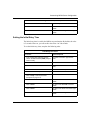
Selecting a Data Encapsulation Method ................................................................1-14
Selecting LLC/SNAP Encapsulation ................................................................1-15
Selecting NULL Encapsulation (VC-Based Multiplexing) ................................1-15
Encapsulation Rules for PVCs ...............................................................................1-16
PVC Access Methods ............................................................................................1-17
Multiple PVCs ..................................................................................................1-17
One PVC .........................................................................................................1-18
Hybrid Access PVCs .......................................................................................1-19
Using Hybrid PVCs for Transparent Bridging ...................................................1-21
SVC Access Methods ............................................................................................1-22
Assigning ATM Addresses .....................................................................................1-22
Entering an ATM Address Network Prefix .......................................................1-23
Entering an ATM Address User Part ................................................................1-23
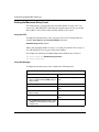
ATM Traffic Parameters ..........................................................................................1-23
Using the PCR .................................................................................................1-24
Using the SCR .................................................................................................1-25
Using the MBS .................................................................................................1-26
ARP and Inverse ARP Support ..............................................................................1-27
ATM Error Checking ...............................................................................................1-27
Simulated Multicast Packet Support .......................................................................1-27
Converting Mb/s to Cells/s .....................................................................................1-27
Classical IP over ATM Concepts ...................................................................................1-28
ATM Address Resolution ........................................................................................1-31
Configuring an ATM Service Record for ATMARP .................................................1-32
Configuring an ATM Address for an Adjacent Host ................................................1-33
ATM LAN Emulation Concepts .....................................................................................1-33
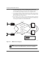
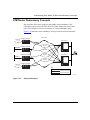
LAN Emulation Connectivity ...................................................................................1-33
LAN Emulation Components ..................................................................................1-34
LAN Emulation Configuration Server ...............................................................1-34
LAN Emulation Clients .....................................................................................1-34
LAN Emulation Server .....................................................................................1-34
Broadcast and Unknown Server ......................................................................1-35
Redundant LES/BUS .............................................................................................1-35
vi
117374-C Rev 00
LAN Emulation States ............................................................................................1-36
Initial State .......................................................................................................1-37
LECS Connect State .......................................................................................1-37
Configure State ................................................................................................1-37
Join State .........................................................................................................1-37
Initial Registration State ...................................................................................1-38
BUS Connect State .........................................................................................1-38
Operational State .............................................................................................1-38
Multi-Protocol over ATM Concepts ...............................................................................1-39
MPOA Logical Components ...................................................................................1-39
MPOA Basic Elements ...........................................................................................1-40
Establishing a Network Cut-Through .....................................................................1-41
ATM Router Redundancy Concepts .............................................................................1-43
PVC Operations and Management Concepts ..............................................................1-44
OAM Loopback ......................................................................................................1-45
OAM Alarms ...........................................................................................................1-45
For More Information ....................................................................................................1-46
Where to Go Next .........................................................................................................1-47
Chapter 2
Understanding MPLS
MPLS General Information .............................................................................................2-2
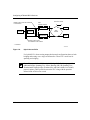
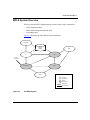
MPLS System Overview .................................................................................................2-3
Label Distribution Entity ...........................................................................................2-4
MPLS Label Management ........................................................................................2-4
Forwarding ...............................................................................................................2-4
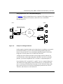
The MPLS Network ........................................................................................................2-5
Label Switching Router ............................................................................................2-6
Label Edge Router ...................................................................................................2-6
Supported Protocols .......................................................................................................2-7
For More Information ......................................................................................................2-7
Where to Go Next ...........................................................................................................2-8
117374-C Rev 00
vii
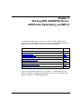
Chapter 3
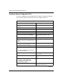
Starting ATM, ATM MPOA Server, ATM Router Redundancy, and MPLS
Starting Configuration Tools ...........................................................................................3-2
Starting ATM Services ....................................................................................................3-2
Using the BCC .........................................................................................................3-2
Adding ATM to the Configuration .......................................................................3-3
Enabling Signaling (LANE and Classical IP Service Records Only) .................3-3
Defining an ATM Service Record .......................................................................3-4
Adding PVCs .....................................................................................................3-5
Adding Protocols to an ATM Service Record .....................................................3-6
Using Site Manager ..................................................................................................3-8
Creating an ATM Circuit .....................................................................................3-8
Defining an ATM Service Record .......................................................................3-9
Enabling Protocols on an ATM Service Record ...............................................3-12
Adding PVCs ...................................................................................................3-14
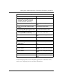
Starting the MPOA Server ............................................................................................3-15
Configuring LAN Emulation Clients ........................................................................3-15
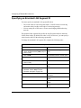
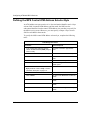
Creating an MPS Service Record ..........................................................................3-17
Adding an MPS to the MPS Service Record ..........................................................3-18
Mapping an MPS to a LEC .....................................................................................3-19
Configuring an SVC Control Connection ...............................................................3-20
Configuring the MPS ..............................................................................................3-22
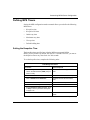
Starting ATM Router Redundancy ................................................................................3-23
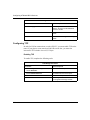
Creating a Group Configuration File ......................................................................3-24
Creating Member Configuration Files ....................................................................3-26
Creating a Primary Configuration File .............................................................3-26
Creating a Secondary Configuration File .........................................................3-27
Downloading Member Configuration Files to the Routers ......................................3-28
Deleting ATM from the Router ......................................................................................3-29
Using the BCC .......................................................................................................3-29
Using Site Manager ................................................................................................3-29
viii
117374-C Rev 00
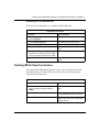
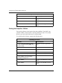
Starting MPLS ..............................................................................................................3-30
Creating an ATM Circuit .........................................................................................3-30
Adding the LDP Session Record ............................................................................3-31
Adding Protocols to an LDP Session Record .........................................................3-32
Adding Protocols to the LDP Session ..............................................................3-32
Adding Protocols to an Existing Record ..........................................................3-33
Adding IP Adjacent Hosts ......................................................................................3-35
Defining IP Static Routes for LDP ..........................................................................3-36
Enabling MLM ........................................................................................................3-37
Configuring TCP ....................................................................................................3-38
Enabling TCP ...................................................................................................3-38
Increasing the TCP Window Size ....................................................................3-39
Deleting MPLS from the Interface .................................................................................3-39
Where to Go Next .........................................................................................................3-40
Chapter 4
Customizing an ATM Interface
Disabling and Reenabling the ATM Driver ......................................................................4-2
Defining the Interface MTU .............................................................................................4-3
Defining the Data Path Notify Function ...........................................................................4-5
Defining the SVC Inactivity Timeout ...............................................................................4-7
Assigning the Framing Mode ..........................................................................................4-9
Defining the Clocking Signal Source ............................................................................4-10
Specifying DS-3 Line Buildout ......................................................................................4-11
Turning DS-3 Scrambling On and Off ...........................................................................4-12
Enabling and Disabling Per-VC Clipping ......................................................................4-14
Disabling and Reenabling an ATM Interface .................................................................4-15
Disabling and Reenabling Signaling on an Interface ....................................................4-17
Autogenerating ATM Addresses ...................................................................................4-18
Enabling or Disabling the Hardware MAC Address Feature ..................................4-18
Entering a MAC Address Override Value ...............................................................4-19
Defining the Maximum Number of VPCs ......................................................................4-21
Defining the Maximum Number of VCCs ......................................................................4-21
Where to Go Next .........................................................................................................4-22
117374-C Rev 00
ix
Chapter 5
Customizing Signaling
Defining Signaling ...........................................................................................................5-2
Disabling and Reenabling Signaling ........................................................................5-3
Assigning the UNI Signaling Protocol Standard .......................................................5-5
Specifying the Maximum Number of SVC Applications ...........................................5-7
Setting Connection Thresholds ................................................................................5-9
Setting the Maximum Number of Point-to-Point Connections ............................5-9
Setting the Maximum Number of Point-to-Multipoint Connections ..................5-10
Setting the Maximum Number of Parties in Multipoint Connections ................5-12
Setting the Minimum Memory Threshold ...............................................................5-13
Defining Signaling Timer Resolution ......................................................................5-14
Defining Signaling Timers .............................................................................................5-15
Defining Retransmissions ......................................................................................5-22
Setting the Number of Allowable Restart Messages .......................................5-22
Setting the Number of Allowable Status Enquiries ..........................................5-23
Disabling and Reenabling Restarts ........................................................................5-24
Pacing Calls ...........................................................................................................5-25
Defining ILMI ................................................................................................................5-26
Disabling and Reenabling ILMI ..............................................................................5-26
Modifying ILMI Timers and Retry Counters ...........................................................5-28
Setting the ILMI Get Request Timer ................................................................5-28
Setting the ILMI Get Request Retry Count ......................................................5-29
Setting the ILMI Get Next Request Timer ........................................................5-30
Setting the ILMI Get Next Request Retry Count ..............................................5-31
Setting the ILMI Set Request Timer ................................................................5-33
Setting the ILMI Set Request Retry Count ......................................................5-34
Defining Control VCs ....................................................................................................5-35
Changing VPI Numbers .........................................................................................5-36
Changing VCI Numbers .........................................................................................5-38
Modifying Control VC Traffic Parameters ...............................................................5-41
Setting the PCR ...............................................................................................5-41
Setting the SCR ...............................................................................................5-45
Setting the MBS ...............................................................................................5-47
x
117374-C Rev 00
Modifying the Maximum AAL CPCS SDU Size ......................................................5-51
Setting the Transmit SDU Size ........................................................................5-51
Setting the Receive SDU Size .........................................................................5-54
Defining SSCOP/Signaling AAL ...................................................................................5-57
Disabling and Reenabling SSCOP/SAAL ..............................................................5-58
Defining the Link Connection Arbitration ................................................................5-59
Modifying SAAL Timers ..........................................................................................5-61
Defining PDU Values ..............................................................................................5-63
Setting the SSCOP Maximum Connection Control Value ................................5-63
Setting the SSCOP Maximum Poll Data Value ................................................5-65
Setting the SSCOP Maximum STAT PDU Value ..............................................5-66
Where to Go Next .........................................................................................................5-68
Chapter 6
Customizing PVC Service Records and PVCs
Disabling and Reenabling a PVC Service Record ..........................................................6-2
Defining the Service Record MTU ..................................................................................6-3
Changing the Service Name ..........................................................................................6-5
Deleting a Service Record ..............................................................................................6-6
Designating a PVC as Hybrid/Bridged ...........................................................................6-7
Disabling and Reenabling a PVC ...................................................................................6-9
Modifying ATM Traffic Parameters ................................................................................6-11
Setting the PCR .....................................................................................................6-11
Setting the SCR .....................................................................................................6-13
Setting the MBS .....................................................................................................6-15
Modifying the Maximum AAL CPCS SDU Size ............................................................6-17
Setting the Transmit SDU Size ...............................................................................6-17
Setting the Receive SDU Size ...............................................................................6-19
Assigning a Data Encapsulation Type ..........................................................................6-20
Changing PVC OAM Parameters .................................................................................6-22
Copying a PVC .............................................................................................................6-23
Deleting a PVC .............................................................................................................6-24
Where to Go Next .........................................................................................................6-26
117374-C Rev 00
xi
Chapter 7
Customizing Classical IP Service Records
Disabling and Reenabling a Classical IP Service Record ..............................................7-2
Disabling and Reenabling User Part Autogeneration .....................................................7-4
Entering an ATM Address Network Prefix ......................................................................7-6
Entering an ATM Address User Part ...............................................................................7-8
Deleting a Service Record ............................................................................................7-10
Where to Go Next .........................................................................................................7-11
Chapter 8
Customizing LAN Emulation Service Records and Clients
Disabling and Reenabling a LANE Service Record ........................................................8-2
Disabling and Reenabling User Part Autogeneration .....................................................8-3
Entering an ATM Address Network Prefix ......................................................................8-5
Entering an ATM Address User Part ...............................................................................8-6
Selecting a LEC Configuration Mode .............................................................................8-8
Assigning an Emulated LAN Name ..............................................................................8-10
Assigning an Emulated LAN Type ................................................................................8-12
Specifying an Emulated LAN Segment ID ....................................................................8-14
Disabling and Reenabling the LANE Client ..................................................................8-15
Specifying an Owner ....................................................................................................8-16
Assigning ATM LES Addresses ....................................................................................8-17
Disabling and Reenabling a LES Entry ..................................................................8-19
Changing the LE Server Name .....................................................................................8-21
Inserting a LES Address Out of Sequence ............................................................8-22
Modifying a LES Entry ...........................................................................................8-23
Deleting a LES Entry ..............................................................................................8-24
Setting the Maximum Data Frame Size ........................................................................8-26
Controlling Unknown Frame Distribution ......................................................................8-28
Setting a Maximum Unknown Frame Count ...........................................................8-28
Specifying a Maximum Unknown Frame Time .......................................................8-30
Modifying LEC Timers and Retry Counters ..................................................................8-32
Setting the Control Timeout ...................................................................................8-32
Disabling and Reenabling the VCC Timeout Period ..............................................8-34
Setting the Maximum Retry Count .........................................................................8-36
Setting the Aging Time ...........................................................................................8-37
xii
117374-C Rev 00
Setting the Forward Delay Time .............................................................................8-39
Specifying the Expected LE_ARP Response Time ................................................8-40
Setting the Path Switching Delay ...........................................................................8-42
Modifying Flush Protocol Variables ...............................................................................8-44
Disabling and Reenabling the Flush Protocol ........................................................8-44
Setting the Flush Timeout ......................................................................................8-46
Specifying a LECS ATM Address .................................................................................8-48
Enabling and Disabling LAN Emulation Version 2 ........................................................8-49
Deleting a Service Record ............................................................................................8-50
Where to Go Next .........................................................................................................8-52
Chapter 9
Customizing MPOA Server Configuration
Disabling and Reenabling the MPOA Service Record ....................................................9-2
Setting the MPS Address Generating Mode ...................................................................9-3
Specifying the MPS Control ATM Address .....................................................................9-4
Setting the Control ATM Address Network Prefix .....................................................9-4
Setting the Control ATM Address User Part .............................................................9-5
Disabling and Reenabling Individual MPOA Servers ......................................................9-6
Specifying the MPS Configuration Mode ........................................................................9-7
Specifying a LECS ATM Address ...................................................................................9-8
Defining the MPS Control ATM Address Selector Byte ................................................9-10
Defining MPS Timers ....................................................................................................9-11
Setting the Keepalive Time ....................................................................................9-11
Setting the Keepalive Lifetime ................................................................................9-12
Setting the Initial Retry Time ..................................................................................9-13
Setting the Maximum Retry Time ...........................................................................9-14
Setting the Give Up Time .......................................................................................9-15
Setting the Default Holding Time ...........................................................................9-16
Defining MPS Cache Values ........................................................................................9-17
Setting the Initial Cache Size .................................................................................9-17
Setting the Maximum Cache Size ..........................................................................9-18
Deleting an Individual MPS ..........................................................................................9-19
Deleting MPOA from the Interface ................................................................................9-20
Where to Go Next .........................................................................................................9-21
117374-C Rev 00
xiii
Chapter 10
Customizing ATM Router Redundancy
Setting the ATM Router Redundancy Monitoring Timer ...............................................10-2
Where to Go Next .........................................................................................................10-3
Chapter 11
Customizing MPLS Configuration
Customizing LDP Parameters ......................................................................................11-2
Disabling and Reenabling LDP ..............................................................................11-2
Changing the Local IP Address ..............................................................................11-3
Specifying a Local TCP Port ..................................................................................11-4
Specifying a Remote IP Address ...........................................................................11-5
Specifying a Remote TCP Port ..............................................................................11-6
Specifying the Routes Configuration Mode ............................................................11-7
Specifying a Hold Time ..........................................................................................11-8
Specifying a Protocol for MPLS Route Configuration .............................................11-9
Enabling and Disabling Aggregation ....................................................................11-10
Disabling and Reenabling MLM Administrative Status ...............................................11-11
Customizing Default VC Parameters ..........................................................................11-12
Disabling and Reenabling Default VC Admin Status ............................................11-12
Specifying the Default VCL VPI Number ..............................................................11-13
Specifying the Default VCL VCI Number .............................................................11-14
Specifying the Default VC VPI Range ..................................................................11-15
Specifying the Default VC VCI Minimum Range ..................................................11-16
Specifying the Default VC VCI Maximum Range .................................................11-17
Modifying Default VC Traffic Parameters ..............................................................11-18
Setting the Default VC Transmit PCR ............................................................11-18
Setting the Default VC Transmit SCR ............................................................11-19
Setting the Default VC Transmit MBS ............................................................11-20
Setting the Default VC Receive PCR .............................................................11-22
Setting the Default VC Receive SCR .............................................................11-22
Setting the Default VC Receive MBS ............................................................11-24
Modifying the Default VC Maximum AAL CPCS SDU Size ..................................11-25
Setting the Transmit SDU Size ......................................................................11-25
Setting the Receive SDU Size .......................................................................11-26
Specifying the AAL Encapsulation Type ...............................................................11-27
xiv
117374-C Rev 00
Specifying the Default VC Transmit QOS Class ...................................................11-28
Specifying the Default VC Receive QOS Class ...................................................11-28
Specifying the Default VC AAL Type ....................................................................11-28
Specifying the Default VC Congestion Indication .................................................11-28
Enabling and Disabling the Default VC Cell Loss Priority ....................................11-28
Enabling and Disabling Default VC Transmit Tagging ..........................................11-28
Enabling and Disabling Default VC Receive Tagging ...........................................11-28
Customizing LDP Static Route Parameters ................................................................11-29
Enabling and Disabling Static Routes ..................................................................11-29
Specifying a Destination Route Prefix ..................................................................11-30
Specifying a Route Mask .....................................................................................11-31
Where to Go Next .......................................................................................................11-33
Appendix A
Site Manager Parameters
Accessing ATM Parameters ........................................................................................... A-2
Using the Window Path ........................................................................................... A-2
Select Connection Type Window ...................................................................... A-2
Edit ATM Connector Window ............................................................................ A-3
Edit MPLS Connector Window ......................................................................... A-4
Using the Menu Path ............................................................................................... A-4
Accessing Global ATM Signaling Attributes ...................................................... A-5
Accessing Global ATM Interface Attributes ....................................................... A-5
ATM Line Parameters .................................................................................................... A-6
ATM Interface Parameters ........................................................................................... A-12
ATM Service Record Parameters ................................................................................ A-15
ATM Virtual Channel Link Parameters ......................................................................... A-21
LAN Emulation Parameters ......................................................................................... A-27
LES Parameters .......................................................................................................... A-37
ATM Signaling Parameters .......................................................................................... A-39
ATM ILMI Signaling Parameters .................................................................................. A-55
Signaling and ILMI Control VC Parameters ................................................................. A-58
ATM Signaling AAL Parameters ................................................................................... A-63
MPOA Parameters ....................................................................................................... A-67
ATM Router Redundancy Parameter ........................................................................... A-75
OAM Parameters ......................................................................................................... A-76
117374-C Rev 00
xv
MPLS Parameters ....................................................................................................... A-79
LDP Parameters .................................................................................................... A-79
MLM Parameter ..................................................................................................... A-83
Static Route Parameters ....................................................................................... A-83
Default VC Parameters ......................................................................................... A-84
NHRP Parameters ....................................................................................................... A-94
ATMARP Parameters ................................................................................................. A-102
Adjacent Host Parameters ......................................................................................... A-104
Appendix B
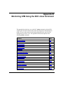
Monitoring ATM Using the BCC show Command
show atm interfaces ....................................................................................................... B-2
show atm line ................................................................................................................. B-3
show atm services ......................................................................................................... B-6
show atm signaling ........................................................................................................ B-6
show atm stats vcs ........................................................................................................ B-7
show atm vcs ................................................................................................................. B-8
show classical-ip configuration ...................................................................................... B-9
show classical-ip interface ............................................................................................. B-9
show classical-ip stats ................................................................................................. B-10
show classical-ip table ................................................................................................. B-10
show dsx3 circuits ....................................................................................................... B-11
show dsx3 current ....................................................................................................... B-12
show dsx3 history ........................................................................................................ B-15
show lane clients ......................................................................................................... B-19
show lane configuration ............................................................................................... B-20
show lane data-vcs ...................................................................................................... B-20
show lane le-arp .......................................................................................................... B-21
show lane le-rd-arp ...................................................................................................... B-22
show lane les ............................................................................................................... B-23
show lane macs ........................................................................................................... B-23
show lane servers ........................................................................................................ B-24
show lane stats ............................................................................................................ B-25
show sonet circuits ...................................................................................................... B-26
show sonet current ...................................................................................................... B-27
show sonet history ....................................................................................................... B-30
xvi
117374-C Rev 00
Appendix C
Configuring NHRP for ATM Services
NHRP Overview ............................................................................................................ C-2
NHRP Message Exchange ..................................................................................... C-2
Configuring NHRP on an Unconfigured ATM Interface .................................................. C-3
Adding NHRP to an Existing ATM Interface ................................................................... C-6
Editing an NHRP Record ............................................................................................... C-8
Disabling an NHRP Record ........................................................................................... C-9
Deleting NHRP .............................................................................................................. C-9
Index
117374-C Rev 00
xvii
Figures
Figure 1-1.
ATM Cell ...................................................................................................1-2
Figure 1-2.
ATM Cell Header ......................................................................................1-3
Figure 1-3.
ATM Transmission Components ...............................................................1-5
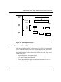
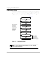
Figure 1-4.
B-ISDN ATM Protocol Reference Model ..................................................1-6
Figure 1-5.
ATM Adaptation Layer 5 ...........................................................................1-9
Figure 1-6.
Multiple PVCs per Service Record ........................................................1-17
Figure 1-7.
One PVC per Service Record ................................................................1-19
Figure 1-8.
Hybrid Access PVCs ..............................................................................1-20
Figure 1-9.
Example of a Bridged Network ..............................................................1-21
Figure 1-10. ATM Address Components ....................................................................1-22
Figure 1-11. IP Local Area Network ...........................................................................1-29
Figure 1-12. IP Logical IP Subnet ..............................................................................1-30
Figure 1-13. LAN Emulation States ............................................................................1-36
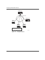
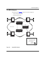
Figure 1-14. MPOA with Cut-Through VC ..................................................................1-42
Figure 1-15. Router Redundancy ...............................................................................1-43
Figure 2-1.
The MPLS System ...................................................................................2-3
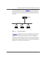
Figure 2-2.
Sample MPLS Network ............................................................................2-5
Figure 5-1.
SVC/PVC Signaling Protocol Stack .........................................................5-2
Figure 5-2.
SVC/PVC Signaling Protocol Stack .......................................................5-57
117374-C Rev 00
xix
Tables
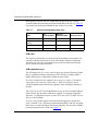
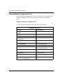
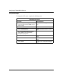
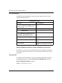
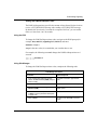
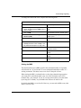
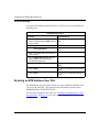
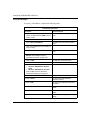
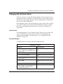
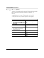
Table 1-1.
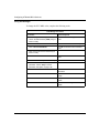
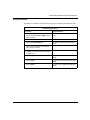
Maximum Bandwidth by Media Type ........................................................1-8
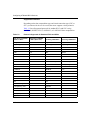
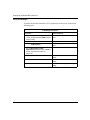
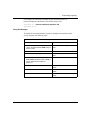
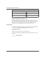
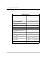
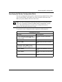
Table 1-2.
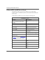
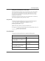
Protocols Supported for Standard PVCs and SVCs .............................1-10
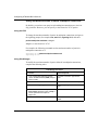
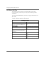
Table 1-3.
Locating and Using Site Manager Protocol Menus ................................1-12
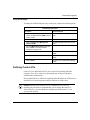
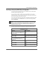
Table 1-4.
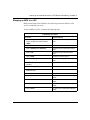
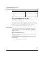
Assigning Data Encapsulation to Individual PVCs .................................1-16
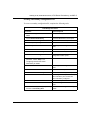
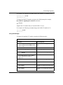
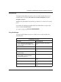
Table 3-1.
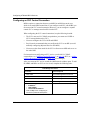
Service Record Protocol Support ............................................................3-6
Table 3-2.
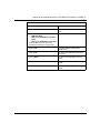
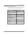
Valid Data Encapsulation Types for PVCs and SVCs ..............................3-9
Table 4-1.
Supported Framing Modes for ATM Interfaces .........................................4-9
Table 5-1.
Signaling Timer Descriptions ................................................................5-15
Table 5-2.
Valid PCR Ranges .................................................................................5-41
Table 5-3.
Valid SCR Ranges .................................................................................5-45
Table 5-4.
SSCOP/SAAL Timer Descriptions ........................................................5-61
Table 6-1.
Valid PCR Ranges .................................................................................6-11
Table 6-2.
Valid SCR Ranges .................................................................................6-13
117374-C Rev 00
xxi
Preface
This guide describes asynchronous transfer mode (ATM) and Multiprotocol Label
Switching (MPLS) and what you do to start and customize these services on a Bay
Networks® router.
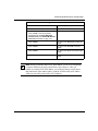
You can use the Bay Command Console (BCC™) or Site Manager to configure
ATM on a router. BCC supports some ATM features. However, some features are
not supported and must be configured using Site Manager. In this guide, you will
find instructions for using both the BCC and Site Manager.
To configure MPLS, you must use Site Manager.
Before You Begin
Before using this guide, you must complete the following procedures. For a new
router:
•
Install the router (see the installation guide that came with your router).
•
Connect the router to the network and create a pilot configuration file (see
Quick-Starting Routers).
Make sure that you are running the latest version of Bay Networks BayRS™ and
Site Manager software. For information about upgrading BayRS and Site
Manager, see the upgrading guide for your version of BayRS.
117374-C Rev 00
xxiii
Configuring ATM and MPLS Services
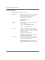
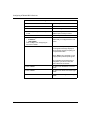
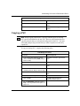
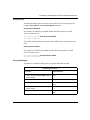
Text Conventions
This guide uses the following text conventions:
angle brackets (< >)
Indicate that you choose the text to enter based on the
description inside the brackets. Do not type the
brackets when entering the command.
Example: If the command syntax is:
ping <ip_address>, you enter:
ping 192.32.10.12
bold text
Indicates text that you need to enter and command
names and options.
Example: Enter show ip {alerts | routes}
Example: Use the dinfo command.
braces ({})
Indicate required elements in syntax descriptions
where there is more than one option. You must choose
only one of the options. Do not type the braces when
entering the command.
Example: If the command syntax is:
show ip {alerts | routes}, you must enter either:
show ip alerts or show ip routes.
brackets ([ ])
Indicate optional elements in syntax descriptions. Do
not type the brackets when entering the command.
Example: If the command syntax is:
show ip interfaces [-alerts], you can enter either:
show ip interfaces or show ip interfaces -alerts.
xxiv
117374-C Rev 00
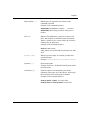
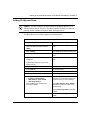
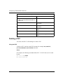
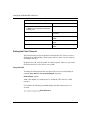
Preface
ellipsis points (. . . )
Indicate that you repeat the last element of the
command as needed.
Example: If the command syntax is:
ethernet/2/1 [<parameter> <value>] . . ., you enter
ethernet/2/1 and as many parameter-value pairs as
needed.
italic text
Indicates file and directory names, new terms, book
titles, and variables in command syntax descriptions.
Where a variable is two or more words, the words are
connected by an underscore.
Example: If the command syntax is:
show at <valid_route>
valid_route is one variable and you substitute one value
for it.
screen text
Indicates system output, for example, prompts and
system messages.
Example: Set Bay Networks Trap Monitor Filters
separator ( > )
Shows menu paths.
Example: Protocols > IP identifies the IP option on the
Protocols menu.
vertical line ( | )
Separates choices for command keywords and
arguments. Enter only one of the choices. Do not type
the vertical line when entering the command.
Example: If the command syntax is:
show ip {alerts | routes}, you enter either:
show ip alerts or show ip routes, but not both.
117374-C Rev 00
xxv
Configuring ATM and MPLS Services
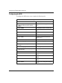
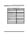
Acronyms
xxvi
AAL
ATM adaptation layer
ABR
available bit rate
AFI
authority and format identifier
AIS
alarm indication signal
ALC
adaptation layer controller
ARE
ATM Routing Engine
ARP
Address Resolution Protocol
ATM
asynchronous transfer mode
BFE
Blacker front-end encryption
B-ISDN
Broadband Integrated Services Digital Network
BUS
broadcast and unknown server
CLP
cell loss priority
CPCS
common part convergence sublayer
CS
convergence sublayer
CSU
channel service unit
DCE
data communication equipment
DDN
Defense Data Network
DSU
data service unit
DTE
data terminal equipment
ELAN
emulated local area network
ER
error recovery
FIB
forwarding information base
HEC
header error control
IETF
Internet Engineering Task Force
ILI
Intelligent Link Interface
ILMI
Interim Local Management Interface
IP
Internet Protocol
117374-C Rev 00
Preface
117374-C Rev 00
IPX
Internetwork Packet Exchange
ITU-T
International Telecommunication Union - Telecommunication
Standardization Sector
LANE
local area network emulation
LDP
label distribution protocol
LE
LAN emulation
LEC
LAN emulation client
LECS
LAN emulation configuration server
LER
label edge router
LES
LAN emulation server
LIS
logical IP subnet
LLC
Logical Link Control
LUNI
LAN emulation UNI
MAC
media access control
MBS
maximum burst size
MCR
minimum cell rate
MCS
multicast server
MIB
management information base
MPC
Multi-Protocol over ATM client
MPLS
Multiprotocol Label Switching
MPOA
Multi-Protocol over ATM
MPS
MPOA server
MTU
maximum transmission unit
NHRP
Next Hop Resolution Protocol
NML
Native Mode LAN
NMS
network management station
NNI
network-to-network interface
OAM
Operations and Management
OAM&P
Operations, Administration, Maintenance and Provisioning
xxvii
Configuring ATM and MPLS Services
xxviii
OC-3
Optical Carrier-level 3
OSI
Open Systems Interconnection
OSPF
Open Shortest Path First
PCR
peak cell rate
PD
poll data
PDN
Public Data Network
PDU
protocol data unit
PHY
physical [layer]
PMD
physical medium dependent
PT
payload type
PVC
permanent virtual circuit
RDI
remote defect indication
RIP
Routing Information Protocol
RS
resynchronization
SAAL
signaling AAL
SAP
service access point
SAR
segmentation and reassembly
SCR
sustainable cell rate
SD
sequenced data
SDU
service data unit
SMDS
Switched Multimegabit Data Service
SNAP
Subnetwork Access Protocol
SNMP
Simple Network Management Protocol
SONET/SDH
Synchronous Optical Network/Synchronous Digital Hierarchy
SPE
synchronous payload envelope
SRM
System Resource Module
SSCOP
Service Specific Connection Oriented Protocol
SSCS
service specific convergence sublayer
STP
shielded twisted pair
117374-C Rev 00
Preface
SVC
switched virtual circuit
TOH
transport overhead
UNI
user-to-network interface
UTP
unshielded twisted pair
VBR
variable bit rate
VC
virtual circuit
VCC
virtual channel connection
VCI
virtual channel identifier
VCL
virtual channel link
VPC
virtual path connection
VPI
virtual path identifier
WAN
wide area network
Bay Networks Technical Publications
You can now print Bay Networks technical manuals and release notes free,
directly from the Internet. Go to support.baynetworks.com/library/tpubs/. Find the
Bay Networks product for which you need documentation. Then locate the
specific category and model or version for your hardware or software product.
Using Adobe Acrobat Reader, you can open the manuals and release notes, search
for the sections you need, and print them on most standard printers. You can
download Acrobat Reader free from the Adobe Systems Web site,
www.adobe.com.
You can purchase Bay Networks documentation sets, CDs, and selected technical
publications through the Bay Networks Collateral Catalog. The catalog is located
on the World Wide Web at support.baynetworks.com/catalog.html and is divided
into sections arranged alphabetically:
117374-C Rev 00
•
The “CD ROMs” section lists available CDs.
•
The “Guides/Books” section lists books on technical topics.
•
The “Technical Manuals” section lists available printed documentation sets.
xxix
Configuring ATM and MPLS Services
Make a note of the part numbers and prices of the items that you want to order.
Use the “Marketing Collateral Catalog description” link to place an order and to
print the order form.
How to Get Help
For product assistance, support contracts, information about educational services,
and the telephone numbers of our global support offices, go to the following URL:
http://www.baynetworks.com/corporate/contacts/
In the United States and Canada, you can dial 800-2LANWAN for assistance.
xxx
117374-C Rev 00
Chapter 1
Understanding ATM, MPOA,
ATM Router Redundancy, and OAM
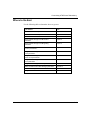
This chapter describes the concepts underlying ATM and, where appropriate, the
specific ways Bay Networks implements these concepts on its routers. It contains
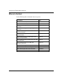
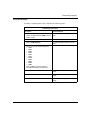
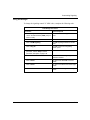
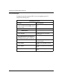
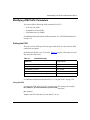
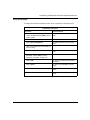
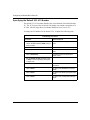
the following information:
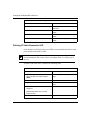
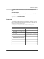
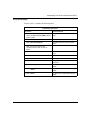
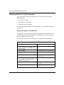
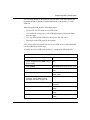
117374-C Rev 00
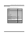
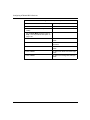
Topic
Page
ATM General Information
1-2
Classical IP over ATM Concepts
1-28
ATM LAN Emulation Concepts
1-33
Multi-Protocol over ATM Concepts
1-39
ATM Router Redundancy Concepts
1-43
PVC Operations and Management Concepts
1-44
For More Information
1-46
Where to Go Next
1-47
1-1
Configuring ATM and MPLS Services
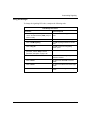
ATM General Information
Asynchronous transfer mode (ATM) is a connection-oriented, cell-based
technology that relays traffic across a Broadband Integrated Services Digital
Network (B-ISDN). ATM provides a cost-effective way of transmitting voice,
video, and data across a network.
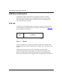
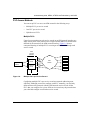
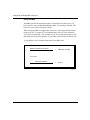
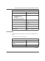
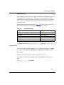
ATM Cells
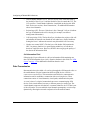
An ATM cell is a fixed-length packet of 53 bytes. It consists of a 5-byte header
containing address information and a fixed, 48-byte information field. Figure 1-1
shows a diagram of an ATM cell.
48-byte
information field
5-byte
header
ATM0001A
Figure 1-1.
ATM Cell
This fixed-length cell size allows you to predict network delays, making ATM
suitable for carrying real-time information (for example, voice and video) as well
as data.
ATM allows the network to operate at a much higher rate than typical
packet-switching protocols (for example, X.25), because it provides no error
protection or flow control. Instead, ATM relies on the source and destination
devices to perform error-recovery functions such as retransmission of lost packets.
1-2
117374-C Rev 00
Understanding ATM, MPOA, ATM Router Redundancy, and OAM
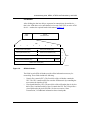
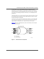
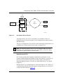
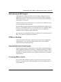
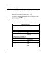
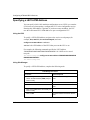
Cell Header
After dividing the data into 48-byte segments for transmission, the end device -that is, the ATM data service unit/channel service unit (DSU/CSU) or native ATM
device -- attaches the required header information (Figure 1-2).
48-byte
information field
5-byte
header
Bits
1
2
3
4
5
6
7
8
Generic flow control (GFC)
Virtual path identifier (VPI)
1
Virtual path identifier (VPI)
Virtual channel identifier (VCI)
2
Virtual channel identifier (VCI)
Virtual channel identifier (VCI)
Payload type (PT)
Header error control (HEC)
3
Cell loss
priority
Bytes
4
5
ATM0002A
Figure 1-2.
ATM Cell Header
The fields in each ATM cell header provide all the information necessary for
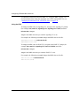
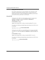
networking. These fields include the following:
117374-C Rev 00
•
Generic flow control (GFC): The first 4 bits of the cell header contain the
GFC. The GFC controls traffic flow onto the ATM network by controlling the
user-to-network interface (UNI).
•
Virtual path identifier (VPI): The next 8 bits of the cell header (that is, the last
half of byte 1 and the first half of byte 2) contain the VPI. The VPI specifies a
virtual path on the physical ATM link. See the next section, “Data
Transmission,” for additional information about virtual paths.
1-3
Configuring ATM and MPLS Services
•
Virtual channel identifier (VCI): The next 16 bits of the cell header (that is,
the last half of byte 2, byte 3, and the first half of byte 4) contain the VCI. The
VCI specifies a virtual channel within the virtual path on the physical ATM
link. See the next section, “Data Transmission,” for additional information
about virtual channels.
•
Payload type (PT): The next 3 bits (that is, bits 5 through 7 of byte 4) indicate
the type of information the cell is carrying (for example, user data or
management information).
•
Cell loss priority (CLP): The last bit of byte 4 indicates the priority of the cell
and whether the network can discard the cell under heavy traffic conditions.
Setting the bit to 1 indicates the network may discard the cell if necessary.
•
Header error control (HEC): The last byte of the header field contains the
HEC. Its primary function is to guard against misdelivery of cells due to
header or single-bit errors. However, the HEC does not gauge the quality of
the data in the information field.
Cell Information Field
Following the 5-byte cell header is a 48-byte information field containing user
data. The ATM adaptation layer (AAL) organizes the data in this field. See “ATM
Layers” on page 1-6 for additional information about the AAL.
Data Transmission
Data transmission (also called cell switching) through the ATM network relies on
the establishment of logical connections between ATM devices. ATM is a
connection-oriented service. This means that an ATM device cannot transmit
information until it establishes a connection with a receiving device. These
connections consist of virtual channels, virtual paths, and transmission paths.
A virtual channel is a logical connection between two communicating ATM
devices. Each virtual channel can carry a different protocol or traffic type. The
virtual channel transports cells that have a common identifier, the VCI, that is part
of the cell header. You can establish virtual channels permanently or set them up
dynamically, allowing the network to adjust itself to the traffic demand.
1-4
117374-C Rev 00
Understanding ATM, MPOA, ATM Router Redundancy, and OAM
A virtual path is a set of virtual channels between a common source and
destination. The virtual channels in a virtual path are logically associated with a
common identifier, the virtual path identifier (VPI), that is part of the cell header.
You can base cell switching on either the VPI alone, or on a combination of the
VPI and VCI.
Virtual paths enable you to separate network transport functions into those related
to an individual logical connection (virtual channel) and those related to a group
of logical connections (virtual path).
A transmission path is a physical connection that comprises several virtual paths,
each virtual path containing several virtual channels. The transmission path can
support multiple virtual paths across a single connection to the network.
Figure 1-3 shows the relationships between the virtual channel, the virtual path,
and the transmission path.
Transmission Path
VC
VP
VP
VC
VC
VP
VP
VC
VC
VP
VP
VC
VP = Virtual path
VC = Virtual channel
ATM0006A
Figure 1-3.
117374-C Rev 00
ATM Transmission Components
1-5
Configuring ATM and MPLS Services
Permanent and Switched Virtual Connections
Virtual channels and virtual paths allow you to establish virtual channel links
(VCLs). You can create VCLs as either permanent virtual circuits (PVCs) or
switched virtual circuits (SVCs). After you establish a PVC, you can transfer
information over it at any time. SVCs activate, through signaling and network
switching, only when there is information ready for transmission.
ATM Layers
The B-ISDN protocol reference model, on which ATM is based, consists of four
layers (Figure 1-4). Each layer communicates only with the layer directly above it
and the layer directly below it.
Higher protocol layer
Convergence sublayer (CS)
Segmentation and reassembly sublayer (SAR)
ATM
adaptation
layer
(AAL)
ATM layer
Transmission convergence sublayer
Physical medium dependent sublayer (PMD)
Physical
layer
(PHY)
ATM0003A
Figure 1-4.
1-6
B-ISDN ATM Protocol Reference Model
117374-C Rev 00
Understanding ATM, MPOA, ATM Router Redundancy, and OAM
The following layers relate directly to how Bay Networks routers support ATM:
•
•
•
Physical layer
ATM layer
ATM adaptation layer (AAL)
Physical Layer
In a Bay Networks Backbone Node (BN®) router, Intelligent Link Interface (ILI)
pairs provide access and processing. An ILI pair consists of a link module and a
processor module that work together to process and transmit information over a
network. Bay Networks provides an ATM Routing Engine (ARE) link module in
conjunction with an ARE processor.
In addition, Bay Networks provides a hub version of the ATM ARE ILI pair, the
Model 5782 ATM router. This single hub module, incorporating the ILI functions
of both the link module and processor module, resides in a System 5000BH
chassis. See Using the Model 5782 ATM Virtual Network Router for more
information.
The ILI pair and the Model 5782 ATM router are functionally identical, and you
configure them in much the same way. Unless otherwise noted, the remainder of
this guide treats the router ILI pair and the Model 5782 as if they were the same.
Depending on the ATM router type, you can connect directly to an ATM network
over any of the following physical interfaces:
117374-C Rev 00
•
Optical carrier level 3 (OC-3)
•
Digital service level 3 (DS-3)
•
E-3 (the European equivalent of the North American DS-3)
1-7
Configuring ATM and MPLS Services
Although Bay Networks uses raw bandwidth to describe line rates, inherent
overhead within the media limits maximum bandwidth for the line. Use Table 1-1
to determine the maximum bandwidth for the media you are using.
Table 1-1.
Maximum Bandwidth by Media Type
Media
Raw
Bandwidth (Mb/s)
Maximum
Bandwidth (Mb/s)
Maximum Cells/s
OC-3 SONET/SDH
155
149.76
353207
DS-3 (Cbit and M23
framing)
44.736
40.704
96000
E-3 (G.832 framing)
34.368
33.920
80000
E-3 (G.751 framing)
34.368
30.528
72000
ATM Layer
The ATM layer defines how two nodes transmit information between them. It is
concerned with the format and size of the cells and the contents of the headers.
The addresses of the cells are meaningful only to the two adjacent local nodes
(that is, usually not to the end nodes).
ATM Adaptation Layer
The ATM adaptation layer (AAL) converts upper-layer protocol data into formats
that are compatible with the requirements of the ATM layer, enabling ATM to
handle different types of information within the same format.
The AAL is divided into two sublayers: the convergence sublayer (CS) and the
segmentation and reassembly (SAR) sublayer. These two sublayers convert
variable-length messages into 48-byte segments, while ensuring the integrity of
the data.
The CCITT (now ITU-T) has defined different types of AALs to handle different
kinds of traffic. Bay Networks ATM routers support a CS function compatible
with AAL 5, as defined in Section 1 of the CCITT (now ITU-T) B-ISDN Protocol
Reference Model (PRM).
In AAL 5, only a trailer attaches to the data from the upper-layer protocols to
create a CS PDU. AAL 5 divides the protocol data unit (PDU) into a 48-octet SAR
PDU; however, it does not add an SAR header and trailer. This 48-octet SAR PDU
becomes the payload of the ATM cell (Figure 1-5).
1-8
117374-C Rev 00
Understanding ATM, MPOA, ATM Router Redundancy, and OAM
Service data unit (SDU)
Service
class
AAL 5
convergence
sublayer
SDU
Trailer
AAL
layer
AAL 5
SAR
layer
SAR PDU
SAR PDU
SAR PDU
ATM cell
ATM
layer
ATM cell
ATM cell
Note: AAL 5 does not attach an SAR header or trailer to the PDU.
ATM0005A
Figure 1-5.
ATM Adaptation Layer 5
Service Records and Virtual Circuits
ATM devices communicate using virtual circuits (VCs). These VCs transmit and
receive ATM cells containing upper-layer protocols. Bay Networks ATM routers
use service records to provide a way of creating logical interfaces (within the
physical ATM interface) for these upper-layer protocols. In essence, these service
records allow you to:
117374-C Rev 00
•
Organize multiple VCs into logical groups.
•
Create direct point-to-point connections.
•
Assign, delete, and modify upper-layer protocols for just one PVC or for a
group of VCs at any given time.
1-9
Configuring ATM and MPLS Services
Supported Protocols
Depending on the data encapsulation type and virtual connection type (PVC or
SVC) you choose for the service record, the router supports various protocols.
Table 1-2 lists all supported protocols for standard PVCs and SVCs using
LLC/SNAP, NLPID, NULL, LANE 802.3, or LANE 802.5 data encapsulation.
Table 1-2.
Protocols Supported for Standard PVCs and SVCs
PVC Using LLC/SNAP,
NLPID, or NULL
SVC Using LLC/SNAP
or NULL (RFC 1577)
SVC Using LANE 802.3
SVC Using LANE 802.5
Bridge
IP
Bridge
Bridge
Spanning Tree
RIP
Spanning Tree
Native Mode LAN
BGP
Native Mode LAN
IP
OSPF
RIP
IPv6
IP
Spanning Tree
IP
RIP
RIP
OSPF
EGP
BGP
BootP
BGP
OSPF
OSPF
BootP
BootP
Router Discovery
IGMP
IGMP
DVMRP
DVMRP
IPX
RIP/SAP
Source Routing
SR Spanning Tree
Translate/LB
NetBIOS
NetBIOS
LLC2
DECnet IV
DECnet IV
DLSw
VINES
VINES
APPN
IPX
IPX
RIP/SAP
OSI
Source Routing
RIP/SAP
XNS
RIP (XNS)
SR Spanning Tree
AppleTalk
Translate/LB
LLC2
XNS
DLSw
RIP (XNS)
AppleTalk
1-10
117374-C Rev 00
Understanding ATM, MPOA, ATM Router Redundancy, and OAM
Caution: Ethernet and token ring emulated LANs can support different
protocols. When adding a protocol to a LANE service record with an
unspecified emulated LAN type, ensure that the protocols you add are
supported by the emulated LAN (Ethernet or token ring) that you want to join.
Things to Remember
When enabling protocols on a service record, keep the following in mind:
•
A PVC service record requires that you add at least one PVC for the service
record to operate.
•
Each ATM service record globally controls:
-- All protocols for any standard PVCs and SVCs that it contains
-- All nonbridging protocols for any hybrid PVCs that it contains
117374-C Rev 00
•
Selecting LANE to run on an SVC service record defines that service record
as belonging to an emulated LAN. Any protocols on that service record
operate as if they were running over a traditional Ethernet or token ring LAN.
•
When running IP over a NULL encapsulated PVC service record, you must
change the Address Resolution parameter to None. You must then add an IP
adjacent host with the MAC address equal to the VPI/VCI of the PVC. See
Configuring IP Services for information about the Address Resolution
parameter.
1-11
Configuring ATM and MPLS Services
Rules for Editing Protocols
Depending on the type of virtual circuit you are using, Site Manager requires you
to add additional protocols, or delete and edit existing protocols, from specific
protocol menus.
Use Table 1-3 to locate the appropriate protocol menu for each access mode.
Table 1-3.
Locating and Using Site Manager Protocol Menus
Site Manager Menu Location
ATM Service Records List window
ATM Virtual Channel Link window
PVCs and SVCs
9
Hybrid PVCs Only
9†
9*
* For nonbridging protocols
†For bridging protocols
Remember, hybrid PVCs use their service record configurations for nonbridging
protocols and their individual configurations for bridging protocols.
Data Encapsulation Methods
Bay Networks ATM routers support multiprotocol encapsulation (as defined in
RFC 1483), enabling the router to multiplex (combine) and demultiplex (separate)
bridged or routed protocol data units (PDUs).
For transmission, the encapsulation process adds a header from 2 to 8 octets in
length to the PDU to allow decoding. The decoding process determines the proper
service access point (SAP).
When receiving information, the encapsulation method evaluates the header to
determine whether the PDU is a valid routed or bridged cell. If it is valid, the
encapsulation method then strips the header from the cell and passes the cell to the
appropriate SAP for routing or bridging.
1-12
117374-C Rev 00
Understanding ATM, MPOA, ATM Router Redundancy, and OAM
You can choose from four data encapsulation types:
•
LANE
•
LLC/SNAP
•
NULL
•
NLPID
How you assign a data encapsulation type and which type takes precedence
depends on the virtual circuit type and, for PVCs, the order in which you assign
the encapsulation type.
Each ATM device must encapsulate PDUs before sending them to the SAR
sublayer.
LANE Encapsulation
LANE provides Ethernet (IEEE 802.3) or token ring (IEEE 802.5) encapsulation
of ATM PDUs for transmission over an emulated LAN. You can assign LANE
encapsulation to SVCs only.
LLC/SNAP Encapsulation
Logical Link Control/Subnetwork Access Protocol (LLC/SNAP; RFC 1483)
allows multiplexing of multiple protocols over a single ATM virtual circuit. In this
approach, an IEEE 802.2 Logical Link Control (LLC) header prefixes each PDU.
You can assign LLC/SNAP encapsulation to:
•
PVC service records
•
SVC service records
•
Individual PVCs
Note: Assigning LLC/SNAP to an SVC service record automatically uses the
technology defined in RFC 1577, Classical IP and ARP over ATM. For
information about RFC 1577, see “Classical IP over ATM Concepts” on
page 1-28.
117374-C Rev 00
1-13
Configuring ATM and MPLS Services
NULL Encapsulation
RFC 1483 refers to NULL encapsulation as “VC-based multiplexing.” This
method performs upper-layer protocol multiplexing implicitly using ATM virtual
circuits. You can assign NULL encapsulation to:
•
PVC service records
•
SVC service records
•
Individual PVCs that are also members of an LLC/SNAP service record
Note: Assigning NULL to an SVC service record automatically uses the
technology defined in RFC 1577, Classical IP and ARP over ATM. For
information about RFC 1577, see “Classical IP over ATM Concepts” on
page 1-28.
NLPID Encapsulation
You can use Network Layer Protocol ID (NLPID; RFC 1490) in an ATM
environment for frame relay/ATM internetworking. You can assign NLPID
encapsulation to PVC service records.
Selecting a Data Encapsulation Method
Generally speaking, the designers of these data encapsulation methods envisioned
that NULL encapsulation would dominate in environments where the dynamic
creation of large numbers of ATM VCs is fast and economical. These conditions
usually exist in private ATM networks.
LLC/SNAP encapsulation is an alternative for environments in which it is not
practical to have a separate VC for each carried protocol (for example, if the ATM
network supports only PVCs, or if billing depends heavily on the number of
simultaneous virtual circuits).
The choice of multiplexing methods that two ATM stations use to exchange
connectionless network traffic depends on the type of virtual circuit involved:
•
1-14
For PVCs, you select the multiplexing method when you manually configure
the connection.
117374-C Rev 00
Understanding ATM, MPOA, ATM Router Redundancy, and OAM
•
For SVCs, the stations themselves negotiate the multiplexing method by
sending B-ISDN signaling messages. These messages include “low-layer
compatibility” information that allows negotiation of AAL5 and the carried
(encapsulated) protocol.
Note: Routed and bridged PDUs are always encapsulated within the payload
field of the AAL5 CPCS PDU, regardless of the selected multiplexing method.
Selecting LLC/SNAP Encapsulation
When the same virtual circuit carries several protocols, select LLC/SNAP
encapsulation. LLC/SNAP encapsulation attaches an LLC/SNAP header before
the PDU. This header includes information that the receiving ATM station needs
to properly process the incoming PDU. For bridged PDUs, this header also
includes the type of the bridged media.
Selecting NULL Encapsulation (VC-Based Multiplexing)
In NULL encapsulation, the carried network protocol is identified implicitly by
the virtual circuit connecting the two ATM stations. Because each protocol must
travel over a separate virtual circuit, there is no need to include explicit
multiplexing information in the payload of the PDU. For this reason, the
bandwidth requirements and processing overhead remain minimal.
You can either manually configure the carried protocol or let the signaling
procedures negotiate it dynamically during call establishment.
NULL encapsulated cells do not receive a header in a routed environment. In a
bridged environment, the content of the PDU itself includes the necessary
information for bridging the multiplexed protocols.
117374-C Rev 00
1-15
Configuring ATM and MPLS Services
Encapsulation Rules for PVCs
How you assign data encapsulation to individual PVCs depends to a degree on the
data encapsulation type you assigned to the service record that contains those
PVCs. Table 1-4 provides suggestions for assigning data encapsulation to PVCs
and hybrid PVCs that reside on these service records.
Table 1-4.
Assigning Data Encapsulation to Individual PVCs
Service Record Data
Encapsulation Type
Individual PVC Data
Encapsulation Type
Hybrid PVC Data
Encapsulation Type
LLC/SNAP
NULL or LLC/SNAP
LLC/SNAP
NULL
NULL or LLC/SNAP
LLC/SNAP
NLPID
NLPID
NLPID
When assigning a data encapsulation type to a PVC or group of PVCs, keep the
following in mind:
1-16
•
When you add a PVC, it reads and uses the data encapsulation type specified
in its ATM service record.
•
You can globally assign a data encapsulation type to all nonhybrid PVCs in a
particular service record, or you can assign a data encapsulation type to
individual group PVCs.
•
If you change the data encapsulation value for the service record, all new
PVCs that you add to that service record use the new value.
•
You must assign a data encapsulation type to hybrid-mode PVCs individually.
You cannot assign data encapsulation to a hybrid-mode PVC using the service
record.
•
When you use the copy function, the new PVC uses the data encapsulation
type of the existing PVC.
•
When running IP over a NULL encapsulated PVC service record, you must
change the Address Resolution parameter to None. You must then add an IP
adjacent host with the MAC address equal to the VPI/VCI of the PVC. See
Configuring IP Services for information about the Address Resolution
parameter.
117374-C Rev 00
Understanding ATM, MPOA, ATM Router Redundancy, and OAM
PVC Access Methods
You can set up PVCs to access an ATM network in the following ways:
•
Multiple PVCs per service record
•
One PVC per service record
•
Hybrid access PVCs
Multiple PVCs
Upper-layer protocols treat each service record on an ATM network interface as a
single access point. These protocols use a single network address to send all traffic
destined for the network to the ATM network interface. Figure 1-6 shows a
conceptual drawing of multiple PVCs accessing an ATM network through each
service record.
ATM
physical
interface
Site A
Service
record
Upper-layer
protocol
Service
record
PVC
PVC
PVC
Site B
ATM
network
PVC
PVC
Site C
Site D
Site E
ATM0018B
Figure 1-6.
Multiple PVCs per Service Record
Configuring multiple PVCs per service record uses network addressing most
efficiently. Although you need to configure each PVC manually, you need only
define and associate protocols with the ATM network service record. All the
PVCs that you configure for a given ATM service record carry the protocols that
you select and configure to run on that service record.
117374-C Rev 00
1-17
Configuring ATM and MPLS Services
Note: When you configure multiple PVCs per service record, all PVCs use the
data encapsulation type that you set for the ATM service record. See “Data
Encapsulation Methods” on page 1-12 for more information.
A configuration using multiple PVCs per service record works best in either fully
meshed environments or in nonmeshed environments where systems not directly
connected to each other have no need to communicate. You can configure multiple
PVCs per service record as long as you do not need to separate protocols by PVC
(that is, all PVCs accept the same protocols).
There are, however, ways to configure upper-layer protocols, such as IP or
Internetwork Packet Exchange (IPX), to allow systems in nonmeshed networks to
fully communicate. See the documentation for these protocols for more
information.
One PVC
A configuration using one PVC per service record works the same way as one
using multiple PVCs per service record. When you define only one PVC per
service record, upper-layer protocols treat the ATM network as a series of direct
point-to-point connections, viewing each PVC as an individual network interface.
You can configure each PVC with different protocols and parameter settings. This
allows you to connect to different network sites using, for example, different types
of data encapsulation (Figure 1-7).
1-18
117374-C Rev 00
Understanding ATM, MPOA, ATM Router Redundancy, and OAM
ATM
physical
interface
Upper layer
protocol
Service
record
PVC
Service
record
PVC
ATM
network
Site A
Site B
ATM0020A
Figure 1-7.
One PVC per Service Record
Assigning one PVC per service record allows you to dedicate a PVC to a
particular protocol, but at the expense of some configuration overhead, memory,
and address space.
This type of configuration is best suited to small, nonmeshed configurations or to
configurations in which protocols must reside on separate PVCs.
Note: The maximum number of PVCs you can configure in this way varies,
depending on the configuration of the router, the number of protocols running
on the circuits, and the number of routing entries.
Hybrid Access PVCs
PVCs do not typically allow bridging in nonmeshed environments. If your
network combines bridging and routing over the same interface, you need to use
the service record portion of each PVC for routing, while at the same time
allowing bridging to operate. To do this, you must define the PVC as a hybrid/
bridged VC.
Defining the PVC as a hybrid/bridged VC allows the bridge to view each PVC as
a separate bridge interface while allowing the routing protocols to view all PVCs
as part of the same interface (Figure 1-8).
117374-C Rev 00
1-19
Configuring ATM and MPLS Services
Bridge protocol sees two interfaces
to the network
ATM
network interface
Direction of data
Hybrid PVC
Routing
protocol
Site A
I
I
ATM
network
Bridge
protocol
I
Hybrid PVC
Site B
Routing protocol sees
one interface to the network
I = Interface
ATM0012B
Figure 1-8.
Hybrid Access PVCs
Use hybrid PVCs when creating nonmeshed network configurations that use both
bridging and routing over a single ATM interface. These PVCs work best for
spanning tree bridging.
Note: When you define a PVC as a hybrid/bridged VC, Site Manager provides
additional Bridge, Spanning Tree, Source Routing (SR), SR Spanning Tree,
Translational/Learning bridge (Translate/LB), and Native Mode LAN (NML)
protocol options. These protocols run on the PVC along with the protocols
defined in the ATM service record.
1-20
117374-C Rev 00
Understanding ATM, MPOA, ATM Router Redundancy, and OAM
Using Hybrid PVCs for Transparent Bridging
In Figure 1-9, traffic is bridged between site A and site B. The bridge (router 1) is
running on the ATM network interface, and its PVCs are not defined as
hybrid/bridged VCs.
Site A
Site B
Router 2
Bridge port sees one
path to Sites A and B
A
C
Router 1
E
ATM
network
Router 3
B
D
F
ATM0013A
Figure 1-9.
Example of a Bridged Network
In this example, when the bridge receives data from site A and does not recognize
the destination address, it tries to direct traffic through another bridge port.
However, because the PVCs are not defined as hybrid/bridged VCs, the ATM
bridge port views the paths to site A and site B as the same.
A bridge does not send the same data over the bridge port from which it just
received the data, so the bridge cannot direct the data to site B. To resolve this
problem, you need to designate the PVCs on router 1 as hybrid/bridged VCs.
If you define the PVCs as hybrid VCs, each PVC acts as a separate bridge port.
This enables the bridge running on the ATM interface to view the traffic from
site A as arriving on a different port from that of site B. When the bridge sends
data, it now has access to all its ports, including the port that accesses site B.
Therefore, data from site A can reach site B.
117374-C Rev 00
1-21
Configuring ATM and MPLS Services
SVC Access Methods
SVCs use signaling messages to dynamically establish, maintain, and clear a
switched virtual connection at the UNI. These messages (as defined by the Q.2931
standard for signaling protocols) allow the router to assess the availability of an
ATM end point (device), establish a connection with that device, maintain that
connection for the duration of data transfer, and then clear the connection when
the transfer is complete.
Assigning ATM Addresses
An ATM address is composed of a network prefix and a user part. Bay Networks
routers use the autogeneration feature to create the user part of the ATM address
by combining the MAC address of the ATM interface with a unique selector byte
to create unique addresses (Figure 1-10). You can also enter ATM addresses
manually.
ATM address
390000000000000000000000000000A20CA98F00
Network prefix
39000000000000000000000000
User part
0000A20CA98F00
MAC address
Selector
byte
0000A20CA98F
00
ATM0037A
Figure 1-10.
1-22
ATM Address Components
117374-C Rev 00
Understanding ATM, MPOA, ATM Router Redundancy, and OAM
Entering an ATM Address Network Prefix
The ATM address network prefix specifies the ATM domain of which the service
record is a part. This 13-byte portion of the ATM address can range from
XX000000000000000000000000 to XXFFFFFFFFFFFFFFFFFFFFFFFF.
The XX byte must contain a value of 39, 45, or 47. These values define the
authority and format identifier (AFI). The AFI byte identifies the group
responsible for allocating the prefix and the format the prefix uses. For more
information about the AFI byte, refer to the ATM Forum UNI specification.
Entering an ATM address network prefix is optional. If you do not enter a network
prefix in the specified range, the service record accepts the first prefix value that it
receives from the switch.
Entering an ATM Address User Part
The ATM address user part (suffix) consists of a 6-byte end-station identifier and a
1-byte selector field. This 7-byte portion of the ATM address can range from
00000000000000 to FEFFFFFFFFFFFF.
You can either allow the router to generate this value automatically, or you can
enter the value manually.
ATM Traffic Parameters
The ATM User-Network Interface Specification defines the following traffic
parameters:
•
Peak cell rate (PCR) -- The upper traffic rate limit for an individual VC
•
Sustainable cell rate (SCR) -- The upper bound on the conforming average
rate of an individual PVC or control VC
•
Maximum burst size (MBS) -- The maximum length of a cell stream allowed
on a particular VC
These parameters help to prioritize and control the traffic on each VC. How you
configure your ATM traffic parameters depends on the characteristics of the
individual connections that you want to set up (for example, the desired maximum
cell rate, average cell rate, and burst size).
117374-C Rev 00
1-23
Configuring ATM and MPLS Services
You can change ATM traffic parameters several times before deciding on a
particular set. The following sections describe the traffic parameters and provide
some basic guidelines for customizing them on an ATM PVC or ATM control VC
(that is, the signaling VC or ILMI VC).
Note: You do not need to manually configure traffic parameters for SVCs (as
you must for PVCs and control VCs), because SVCs dynamically negotiate
these parameters before sending data.
Using the PCR
The PCR specifies the upper traffic limit, in cells/second, that the ATM
connection can support.
How you set the PCR depends on:
•
The optical transmission rate of your ATM device
•
The amount of traffic you expect on a particular VC
•
The rate you want for each VC
When setting the PCR, keep the following considerations in mind:
1-24
•
Each VC can have its own PCR.
•
The PCR cannot exceed the maximum rate for the physical media. For
example, you cannot exceed 149.76 Mb/s for an OC-3c line.
•
The PCR specifies the desired rate for the attached physical media (that is,
OC-3c, DS-3, or E-3). It does not specify the rate for the ATM network as a
whole. For example, you can specify a full 149.76 Mb/s for each PVC or
control VC on an OC-3c connection. However, if the VC ultimately connects
to a lower-speed link (for example, T1 or E1), your PCR is limited to the
maximum rate for that media.
•
ATM VCs may fail to operate with PCR values lower than 128 cells/s.
•
The E-3 framing mode setting affects the maximum PCR setting.
117374-C Rev 00
Understanding ATM, MPOA, ATM Router Redundancy, and OAM
Using the SCR
The SCR is the upper bound on the conforming average rate of an individual PVC
or control VC. The average rate is the number of cells transmitted over the link
divided by the duration of the connection. The duration of the connection is the
total amount of time it takes from connection setup to connection release.
The SCR allows you to define future cell flow on a PVC or control VC in greater
detail than by using only the PCR. The SCR controls the rate over time -- not at a
specific instant of time -- and can help you use your network resources more
efficiently. In other words, the SCR allows sufficient bandwidth for operation, but
does not allow a bandwidth as high as the PCR.
The SCR value maps directly to an MCR (minimum cell rate) value. In other
words, when you configure the SCR on a device, you actually configure the upper
bound of an average rate. Like the SCR, the MCR defines the minimum amount of
guaranteed bandwidth allowed for PVCs and control VCs on the ATM line. The
MCR (that is, SCR) not only controls the rate over time, it guarantees this rate.
When setting the SCR, keep the following considerations in mind:
117374-C Rev 00
•
The SCR maps directly to the MCR.
•
The MCR provides guaranteed bandwidth for PVCs and control VCs while
allowing sufficient bandwidth for SVCs to operate.
•
To be useful, the SCR must not exceed the PCR.
•
If you know the user average rate, set the SCR approximately 10 percent
higher than this value.
•
ATM VCs may fail to operate with SCR values lower than 128 cells/s.
•
Entering 0 for the SCR turns off this function and specifies that the ATM
router uses “best effort” for SCR.
•
The E-3 framing mode setting affects the maximum SCR setting.
1-25
Configuring ATM and MPLS Services
Using the MBS
The MBS specifies the maximum number of sequential cells allowed on a VC
before that VC must relinquish bandwidth to other VCs waiting to transmit. This
burst occurs at or close to the peak cell rate.
When setting the MBS, we suggest that you select a value larger than the largest
packet your PVC or control VC can transmit (that is, the size of the maximum
AAL CPCS transmit SDU). For example, if your VC accepts packets that are less
than 4608 bytes long (PVC default), set your MBS value between 45 and 50 cells.
As a guideline, use this formula to determine your MBS value:
Maximum packet size (in bytes)
48 bytes/cell
=
MBS value (in cells)
=
96 cells
For example:
4608 bytes (default)
48 bytes/cell
ATM0016A
1-26
117374-C Rev 00
Understanding ATM, MPOA, ATM Router Redundancy, and OAM
ARP and Inverse ARP Support
ATM supports the Address Resolution Protocol (ARP), enabling the router to
dynamically resolve IP network layer protocol-to-VPI/VCI address mappings.
ATM learns the address of the virtual circuit by detecting the virtual circuit that
delivered the ARP response.
ATM also supports Inverse ARP. However, you can use Inverse ARP only if both
the local and remote routers support it.
Bay Networks uses both proprietary and standard ARP and Inverse ARP for PVCs
that run IP. The method that the PVC uses depends on how you configure address
resolution for the IP interface. See Configuring IP Services for additional
information about configuring address resolution.
Bay Networks uses standard ARP and Inverse ARP for SVCs running classical IP
(RFC 1577) and SVCs running LAN emulation.
ATM Error Checking
ATM verifies that the VPI/VCI is valid with respect to the PVCs configured for
the ATM circuit. It also verifies the header format. ATM verifies valid SVC
connection through signaling messages.
Simulated Multicast Packet Support
Simulated multicasting is generally used in certain address resolution techniques
and for applications that require the delivery of identical information to multiple
recipients. Bay Networks ATM routers simulate multicasting by sending a copy of
the multicast or broadcast packet to every available virtual circuit on a particular
logical interface.
Converting Mb/s to Cells/s
Several ATM traffic parameters require you to enter values in cells per second
(cells/s). To convert to cells/s, divide the number of bits/s by 424 (the number of
bits per ATM cell).
117374-C Rev 00
1-27
Configuring ATM and MPLS Services
Number of bits/second
Number of bits/ATM cell
=
Number of cells/second
=
235,849 cells/s
For example:
100,000,000 bits/s
424 bits/cell
ATM0021A
Classical IP over ATM Concepts
RFC 1577, Classical IP and ARP over ATM, describes an administrative entity
within an ATM network called a logical IP subnet (LIS). Each ATM LIS consists
of multiple network devices -- hosts and routers -- connected to the ATM network
and configured with interfaces to the same IP subnet.
Each LIS operates and communicates independently in an ATM network. A host
connected to an ATM network communicates directly with other hosts in its own
LIS. To communicate with hosts in another LIS, the host must use an IP router.
This router can connect to multiple LISs.
An ATM LIS must meet the following requirements:
1-28
•
All members of the LIS (hosts and routers) must have the same IP network/
subnet address and mask.
•
All members must be directly connected to the ATM network using SVCs.
•
All members must access hosts outside the LIS through a router.
•
All members must be able to communicate by means of ATM with every other
member of the LIS (that is, the virtual connection topology must be fully
meshed).
117374-C Rev 00
Understanding ATM, MPOA, ATM Router Redundancy, and OAM
An ATM LIS can replace an IP LAN. In Figure 1-11, for example, three IP host
systems and an IP router have interfaces to an Ethernet LAN. To communicate
with each other on the LAN, the devices use the MAC addresses that they obtain
using ARP or static routes. For communication beyond the LAN, the devices use
IP addresses.
Router
140.250.200.1
00 00 A2 00 00 01
140.250.200.0
Host
A
Host
B
140.250.200.2
00 00 A2 00 10 20
140.250.200.3
00 00 A2 00 10 30
Host
C
140.250.200.4
00 00 A2 00 10 40
ATM0035A
Figure 1-11.
IP Local Area Network
In Figure 1-12, an ATM network replaces the LAN interfaces, creating a LIS. For
communication within the LIS, the devices use ATM addresses obtained using
ATMARP; for communication beyond the LIS, the devices use IP addresses.
For example, to send a message to host B, host A uses host B’s ATM address. To
send a message to a host beyond the LIS, host A uses an IP address to identify the
remote host and sends the message to the local router (router A), using the router’s
ATM address. The router then forwards the message.
117374-C Rev 00
1-29
Configuring ATM and MPLS Services
ATMARP client
Router A
ATM network
ATMARP server
Router B
Host
A
Host
B
Host
C
Key
SVC supporting ATM LIS
ATM0037A
Figure 1-12.
1-30
IP Logical IP Subnet
117374-C Rev 00
Understanding ATM, MPOA, ATM Router Redundancy, and OAM
ATM Address Resolution
An address resolution protocol defines a mechanism that enables an IP router to
use the IP address of a network device to learn the physical address of that device.
An Ethernet LAN uses ARP as its address resolution scheme. A LIS uses an
address resolution scheme called ATMARP as defined by RFC 1577.
On a LAN, defined as a broadcast medium, a router obtains the physical address
of a network device by broadcasting an ARP request. In a LIS, which uses a
nonbroadcast ATM medium, a router sends an ATMARP request to an ATMARP
server.
Each IP interface on the LIS opens a VC to the ATMARP server and registers its
IP address and ATM address (Figure 1-12 on page 1-30). Using this information,
the server builds and maintains a table that maps LIS IP addresses to ATM
addresses.
A router that needs the ATM address of a host on the LIS sends an ATMARP
request to the server. When the server returns a response containing the address,
the router extracts the ATM address of the host from the response and opens an
SVC directly to the host using ATM UNI signaling.
If the server does not have an entry for the requested IP address, it returns a
negative acknowledgment, signifying that the destination is unreachable.
117374-C Rev 00
1-31
Configuring ATM and MPLS Services
Configuring an ATM Service Record for ATMARP
When configuring a service record to act as an ATMARP client or server:
•
Define a classical IP service record.
-- Specify SVC as the virtual circuit type for the service record. All network
devices on a LIS must connect over SVCs.
-- Specify LLC/SNAP or NULL as the encapsulation type for the service
record. RFC 1577 defines LLC/SNAP as the encapsulation type for
ATMARP.
For more information about how to create an SVC service record to run
classical IP, see Chapter 3, “Starting ATM, ATM MPOA Server, ATM Router
Redundancy, and MPLS.”
•
Add IP and IP routing protocols to the circuit.
•
Configure ATMARP Mode as either a client or a server.
For a description of the ATM-specific IP parameters necessary for classical IP
ATMARP operation over ATM, see “ATMARP Parameters” on page A-102.
For full compatibility with RFC 1577, you may have to specify a maximum
transmission unit (MTU) size of 9188 bytes. See “Defining the Interface MTU”
on page 4-3 (for the BCC) or the Site Manager Interface MTU parameter
description on page A-6 for additional information about setting the MTU size.
When configuring the router as a client, you must define the server switch address.
The client sends ATMARP requests to the server switch address.
Note: If you remove and replace a link module that is configured as an
ATMARP client, the client loses connectivity until the ATMARP server
registration refresh interval for that client expires (900-second default). This
loss of connectivity occurs only when the client is configured to autogenerate
the ATM address user part (see “Disabling and Reenabling User Part
Autogeneration” on page 7-4 for additional information about autogenerating
ATM addresses).
1-32
117374-C Rev 00
Understanding ATM, MPOA, ATM Router Redundancy, and OAM
Configuring an ATM Address for an Adjacent Host
An adjacent host is a network device on the local LIS. You must configure an
ATM address for all hosts on the LIS that do not use ATMARP.
For a description of the IP parameters required for creating adjacent hosts in a
classical IP over ATM environment, see “Adjacent Host Parameters” on
page A-104.
For more information about adding, editing, and deleting adjacent hosts, see
Configuring IP Services.
ATM LAN Emulation Concepts
LAN emulation allows virtual communication of traditional LAN devices and
applications over an ATM network. An ATM network can run one or more
emulated LANs. However, each emulated LAN is independent of the others and
devices cannot communicate directly across emulated LAN boundaries.
Note: Communication between emulated LANs is possible through routers
and bridges only (possibly implemented on the same end station).
This section provides general information about LAN emulation as described by
the ATM Forum. For more information about LAN emulation, refer to the ATM
Forum document LAN Emulation Over ATM (Version 1.0).
For instructions on how to customize LAN emulation on your ATM router, see
Chapter 8, “Customizing LAN Emulation Service Records and Clients.”
LAN Emulation Connectivity
An emulated LAN can provide Ethernet (IEEE 802.3) or token ring (IEEE 802.5)
connectivity. With an emulated Ethernet or token ring network over ATM,
software applications can interact as if they were connected to a traditional LAN.
117374-C Rev 00
1-33
Configuring ATM and MPLS Services
LAN Emulation Components
Each ATM domain contains a LAN emulation configuration server (LECS). Each
emulated LAN comprises a group of LAN emulation clients (LECs), a LAN
emulation server (LES), and a broadcast and unknown server (BUS). These
servers provide specific LAN emulation services.
LAN Emulation Configuration Server
The LAN emulation configuration server (LECS) assigns individual LE clients to
different emulated LANs. The LECS does this by giving the client the ATM
address of the LAN emulation server (LES). This method allows you to assign a
client to an emulated LAN based on the client’s physical location (ATM address)
or the identity of a LAN destination it represents.
LAN Emulation Clients
The LAN emulation client (LE client or LEC) is the interface, or virtual portion of
an interface, through which an end station forwards data, resolves addresses, and
provides other control functions. The LE client provides the MAC-level emulated
Ethernet or token ring service interface to the upper-layer protocol. It also controls
the LAN emulation UNI (LUNI) interface when communicating with other
devices on the emulated LAN.
The LE client uses the configuration protocol to obtain information from the
LECS. This protocol allows the LE client to locate the LES and set up a
bidirectional, control direct virtual channel connection. The LE client
automatically obtains all of the necessary configuration data (including the LES
address) from the LECS.
LAN Emulation Server
The LES controls and coordinates LE client access to the emulated LAN. When
an LE client joins an emulated LAN, it registers its ATM address with the LES.
When the LES obtains the ATM address of the LE client, it also obtains the
client’s physical location (from the MAC address or route descriptor).
LE clients query the LES to obtain the ATM address associated with a specific
MAC address or route descriptor. After an LE client receives the ATM address of
the LE client it wants to reach, the individual clients communicate directly.
1-34
117374-C Rev 00
Understanding ATM, MPOA, ATM Router Redundancy, and OAM
Broadcast and Unknown Server
To emulate a traditional LAN, the emulated LAN must provide the connectionless
data delivery of a shared network to its LE clients and be able to handle broadcast
and multicast data. The broadcast and unknown server (BUS) fulfills this
requirement by distributing all broadcast, multicast, and unknown traffic to and
from all LE clients on an emulated LAN.
For example, when an LE client sets up its initial configuration, it obtains the
MAC address of the BUS from the LES. Using this MAC address, the LE client
sets up a multicast send virtual channel connection (VCC) to the BUS. In turn, the
BUS registers the LE client as part of its emulated LAN.
To broadcast data, an LE client uses the multicast send VCC to transmit
information to the BUS. The BUS then retransmits the data, through multiple
point-to-point connections or one point-to-multipoint connection, to each LE
client on the emulated LAN.
Redundant LES/BUS
Bay Networks ATM routers support LAN emulation server (LES) and broadcast
and unknown server (BUS) redundancy. This redundancy reduces the risk of
network failure by overcoming a single point of failure in accessing the LES.
117374-C Rev 00
1-35
Configuring ATM and MPLS Services
LAN Emulation States
As defined in the ATM Forum LAN Emulation Over ATM specification, LE clients
enter various states of communication while attempting to join an emulated LAN.
These states (referred to as “phases” by the ATM Forum) indicate the progress of
an LE client as it connects with an emulated LAN (Figure 1-13).
Initial state (1)
LECS connect state (2)
After experiencing
any failure, or
terminating its
connection to the
emulated LAN,
the LE client
returns to the
initial state.
Configure state (3)
Join state (4)
Initial registration state (5)
BUS connect state (6)
Operational state (7)
If the LE client
loses the BUS
connection, it can
attempt to reconnect.
ATM0034A
Figure 1-13.
LAN Emulation States
Note: The numbers that follow each state appear in the ATM LEC status
record (wfAtmLecStatusEntry).
1-36
117374-C Rev 00
Understanding ATM, MPOA, ATM Router Redundancy, and OAM
The following sections briefly describe each LAN emulation state. Refer to the
ATM Forum LAN Emulation Over ATM specification for more information about
LAN emulation states.
Initial State
An LE client always starts in the initial state before attempting to connect to the
LECS.
LECS Connect State
An LE client enters the LECS connect state when it attempts to connect to the
LECS.
Configure State
An LE client enters the configure state when it attempts to retrieve the necessary
information (that is, the ATM address of the LES, LAN type, LAN name,
Maximum MTU, and various timeout values) required to join an emulated LAN.
Join State
An LE client enters the join state when it attempts to join an emulated LAN.
Joining an emulated LAN requires that the LE client:
•
Set up a control VCC to communicate with the LES.
•
Send a join request (containing the client MAC address) to the LES.
•
Accept a control distributed VCC to receive control data from the LES.
•
Receive a valid join response from the LES containing a LAN emulation
client ID (LECID).
Note: Only one ATM LE client per Bay Networks ATM router can join an
emulated LAN at any point in time. However, you can always move a LAN
emulation client to the appropriate emulated LAN using network management
software.
117374-C Rev 00
1-37
Configuring ATM and MPLS Services
Initial Registration State
An LE client enters the initial registration state when it attempts to register
multiple MAC addresses with the LES.
Note: The router LE client provides the MAC address only for its own ATM
interface. Because it does not register multiple MAC addresses, the router
never enters this state. The router LE client acts as a proxy for bridge MAC
addresses not learned on this circuit.
BUS Connect State
An LE client enters the BUS connect state when it attempts to set up a VCC to the
BUS.
Operational State
An LE client enters the operational state after successfully completing the
requirements to join an emulated LAN.
1-38
117374-C Rev 00
Understanding ATM, MPOA, ATM Router Redundancy, and OAM
Multi-Protocol over ATM Concepts
As defined by the ATM Forum, Multi-Protocol over ATM (MPOA) maps routed
and bridged traffic flows to ATM SVCs, thus mitigating the performance
limitations imposed by hop-by-hop routing of individual packets. This technique
of mapping identifiable traffic flows to virtual channels creates network
“shortcuts” between source and destination, and is generally referred to as
cut-through or zero-hop routing.
Cut-through routing is based on the fact that, in most cases, data transfer occurs at
a steady rate of flow. For example, data or file transfer from one legacy Ethernet
LAN to a remote counterpart usually involves multiple frames. A file transfer of
approximately 45 KB requires about 30 Ethernet frames, all addressed to the same
destination.
In an MPOA environment, it is possible to identify the recipient from addressing
data contained within the first frame and to establish an SVC to the recipient.
Then all 30 or so frames can be broken down into approximately 900 ATM cells
and transmitted to the recipient via the virtual channel provided by the SVC.
Network performance improves as the cells follow a predetermined direct path, in
contrast to the hop-by-hop routing of the Ethernet frames. Network performance
improves markedly in the case of steady-stream deterministic data flows, such as
video.
MPOA Logical Components
MPOA operations are based on logical components, which can be implemented in
various configurations of hardware and software. MPOA logical components
include the following:
•
MPOA client
The MPOA client (MPC) resides in an ATM edge device adjacent to the
router. BayRS does not provide MPC functionality. The primary function of
the MPC is to act, in ATM terminology, as an ingress or egress point for traffic
using network cut-throughs.
117374-C Rev 00
1-39
Configuring ATM and MPLS Services
The MPC monitors traffic flows between a local source and remote
destinations. When traffic volume between a source and a destination exceeds
a preconfigured threshold level (for example x packets to the same network
layer address in y seconds), the MPC attempts to set up an SVC between the
source and destination workstations.
In attempting to set up an SVC, the MPC first looks in a local cache of
network layer-to-ATM address mappings. If the MPC finds the destination
address in its local cache, it immediately begins to establish the SVC. If it fails
to locate the destination address in the local cache, it generates an MPOA
address resolution request to an adjacent MPOA server.
•
MPOA router
The MPOA router is a collection of logical functions that map network layer
addresses to ATM addresses. The MPOA router maintains tables of adjacent
network layer (IP), MAC layer, and ATM addresses, in addition to standard
routing tables derived from a routing protocol (generally OSPF or RIP).
MPOA routers communicate over NHRP to map network layer addresses to
ATM addresses. BayRS provides MPOA router functionality to map IP
addresses to their ATM counterparts.
•
MPOA server
The MPOA server (MPS) is a logical function that mediates between local
MPCs and the MPOA router. It receives MPOA address resolution requests
from MPCs and passes them to the MPOA routing function. The MPOA
router, using NHRP, resolves the address and passes the requested ATM
address back to the MPS. The MPS, in turn, forwards the resolved address to
the requesting MPC. BayRS provides MPOA server functionality.
MPOA Basic Elements
MPOA services are dependent on three basic elements:
•
LANE
LANE (LAN emulation) provides transparent support for legacy LANs in an
ATM topology. LANE enables intrasubnet communication, and MPOA
provides intersubnet communication.
1-40
117374-C Rev 00
Understanding ATM, MPOA, ATM Router Redundancy, and OAM
•
Next Hop Resolution Protocol (NHRP)
NHRP is a sophisticated address resolution protocol that maps network layer
addresses (for example, IP addresses) to NBMA addresses (in the case of
BayRS, ATM addresses). For instructions on configuring an NHRP server, see
Appendix C, “Configuring NHRP for ATM Services.”
•
Virtual router
A virtual router is a set of network devices and associated software that
collectively provides the functionality of multiprotocol routed networks.
Establishing a Network Cut-Through
MPOA components and elements function together to establish an SVC between a
source host and a destination host (Figure 1-14).
1.
A local MPC monitors traffic flow and maintains a count of packets addressed
over a specific interval to remote hosts. When the count exceeds a threshold
value, the MPC attempts to establish an SVC to the host.
To establish the virtual connection, the MPC needs the ATM address of the
host.
2.
The MPS first checks a local address resolution cache to map the known
network layer address with an ATM equivalent.
3.
If the cache search fails, the MPC issues an MPOA resolution request to the
local MPS function resident on the adjacent router.
4.
The local MPS hands the resolution request to the MPOA router component.
5.
The MPOA router generates an NHRP address resolution request for the ATM
address of the destination host. Standard routing protocols move the NHRP
request through the network toward the destination host. Eventually, the
NHRP request reaches the egress router, that is, the router that serves the host.
6.
The egress router forwards the request to the remote MPS.
7.
The remote MPS provides the ATM address of the destination host to the
remote MPOA router.
If the destination host is connected to a legacy LAN, the MPS provides the
ATM address of the router that connects to the legacy LAN. If the destination
host is ATM-attached, the MPS provides the ATM address of the destination
host.
117374-C Rev 00
1-41
Configuring ATM and MPLS Services
8.
The remote MPOA router generates an NHRP address resolution reply
containing the ATM address provided by the MPS. Standard routing protocols
move the NHRP reply through the network to the local MPOA router.
9.
After caching the address resolution information, the MPOA router sends the
resolved address to the MPS, which, in turn, sends the resolved address to the
MPC that initiated the resolution process.
10. The local MPC caches the address resolution information and now establishes
an SVC, either directly to the destination host (if that host is an ATM device),
or to the egress router that serves the destination host.
ATM network
ATM MPS
ATM MPC
10BASE-T
ELAN 1
ELAN 2
ATM MPS
ELAN 3
ELAN 4
ATM MPC
10BASE-T
Key
Cut-through VC
Logical connection
NHRP control VC
ATM0055A
Figure 1-14.
MPOA with Cut-Through VC
Note: Creating a separate NHRP control VC is optional. If you configure
NHRP on each LEC, the control information passes over the emulated LAN.
1-42
117374-C Rev 00
Understanding ATM, MPOA, ATM Router Redundancy, and OAM
ATM Router Redundancy Concepts
Bay Networks ATM routers support warm standby router redundancy. This
redundancy protects a network from the irrecoverable failure of an entire ATM
router. You configure routers to be members of a router redundancy group.
Figure 1-15 illustrates router redundancy in a Bay Networks ATM environment.
Centillion 100 switch
ATM network
Token ring
ATM router 1
ELAN 1
Centillion 100 switch
100BASE-T
ELAN 2
Centillion 100 switch
ATM router 2
ELAN 3
10BASE-T
ELAN 4
Centillion 100 switch
Token ring
Key
Physical connection
Logical connection
ATM00002
Figure 1-15.
117374-C Rev 00
Router Redundancy
1-43
Configuring ATM and MPLS Services
Router redundancy requires at least two routers to be members of a router
redundancy group. One router acts as the primary router and provides normal
routing/bridging services. The other router acts as the secondary, backup router
and takes over if the primary router fails.
All members of an ATM router redundancy group must have the following
characteristics:
•
Be the same ATM router type, for example, BCN®, BLN®, or System 5000™.
•
Have the same hardware configuration, including CPU and interface module
types, and slot and port locations of the backed-up interfaces.
•
Have the same software configuration. That is, you must be running the same
router software version and have the same loadable modules configured.
•
Contain both a primary configuration file and a secondary configuration file.
•
Have at least one legacy LAN connection between the routers in the
redundancy group.
Note: Bay Networks recommends at least two legacy LAN connections
between routers in the redundancy group.
PVC Operations and Management Concepts
In most ATM networks, if a PVC fails, the remote device does not receive
notification of the failure at the ATM layer. Instead, the device receives this
information from a non-ATM source such as a routing protocol that operates
above the ATM layer. The PVC Operations and Management (OAM) feature
provides a mechanism by which ATM devices can receive prompt failure
information.
PVC OAM has two methods of detecting PVC failure: loopback and alarms. You
can use either of these methods separately or both methods together. When using
OAM loopback cells, the time can decrease to only a few seconds; when using
OAM alarms, the detection is almost instantaneous.
1-44
117374-C Rev 00
Understanding ATM, MPOA, ATM Router Redundancy, and OAM
OAM Loopback
The OAM loopback method uses loopback cells to detect a lost connection. When
OAM loopback is enabled, the PVC sends loopback cells at a designated interval.
If a remote device does not return loopback responses, and the PVC loses a
specified number of cells, the service record alerts the upper-layer protocol that
the link is down. The PVC continues to send OAM loopback cells over the service
record. When it receives a specified number of OAM loopback responses, it
declares the link operational and begins sending traffic again.
Note: For OAM loopback to function properly, you must configure it on all
PVCs on an interface. Link status is based on the OAM loopback status of all
PVCs on the interface.
OAM Alarms
If the ATM router connects to an ATM switch that uses OAM alarms, you can
enable alarm detection on the ATM router. With OAM alarms enabled, when the
router receives an alarm indication signal (AIS) alarm from the switch, it alerts the
upper-layer protocol that the ATM link is down; it does not wait for an OAM
loopback response from the remote device.
After receiving an AIS alarm, the router sends a remote defect indication (RDI)
response to the switch to indicate that it received the alarm. The switch continues
to send AIS alarms until the link is operational again. If the router does not receive
an AIS alarm for 3 seconds, it declares the link operational and begins sending
traffic again.
117374-C Rev 00
1-45
Configuring ATM and MPLS Services
For More Information
For more information about ATM, refer to the following documents:
ATM Forum. ATM User-Network Interface Specification. Version 3.0. September
1993.
ATM Forum. LAN Emulation Over ATM. Version 1.0. January 1995.
Bellcore Document SR-NWT-001763, Issue 1. Preliminary Report on Broadband
ISDN Transfer Protocols. December 1990.
———, FA-NWT-001109. Broadband ISDN Transport Network Elements
Framework Generic Criteria. December 1990.
———, FA-NWT-001110. Broadband ISDN Switching System Framework
Generic Criteria. December 1990.
De Prycker, M. Asynchronous Transfer Mode: Solution for Broadband ISDN. Ellis
Horwood Limited, 1991.
Grossman, D., E. Hoffman, F. Liaw, A. Malis, A. Mankin, and M. Perez. ATM
Signaling Support for IP over ATM. RFC 1755. Network Working Group.
February 1995.
Handel, R., and M. Huber. Integrated Broadband Networks: An Introduction to
ATM-Based Networks. Reading, Mass.: Addison-Wesley, 1991.
Heinanen, J. Multiprotocol Encapsulation over ATM Adaptation Layer 5.
RFC 1483. Network Working Group. July 1993.
ITU-T. B-ISDN -- ATM Adaptation Layer -- Service Specific Connection Oriented
Protocol (SSCOP). Final Draft. March 10, 1994.
Laubach, M. Classical IP and ARP over ATM. RFC 1577. Network Working
Group. January 1994.
1-46
117374-C Rev 00
Understanding ATM, MPOA, ATM Router Redundancy, and OAM
Where to Go Next
Use the following table to determine where to go next.
If you want to
Go to
Learn about MPLS concepts.
Chapter 2
Start ATM or MPLS.
Chapter 3
Change default settings for ATM interface
parameters.
Chapter 4
Change default settings for ATM signaling
parameters.
Chapter 5
Change default settings for ATM PVC service record Chapter 6
and PVC parameters.
117374-C Rev 00
Change default settings for classical IP service
record parameters.
Chapter 7
Change default settings for LAN Emulation client
service record parameters.
Chapter 8
Change default settings for Multi-Protocol over ATM
server parameters.
Chapter 9
Change default settings for the ATM router
redundancy parameter.
Chapter 10
Change default settings for MPLS parameters.
Chapter 11
Obtain information about Site Manager parameters.
Appendix A
Monitor ATM using the BCC show commands.
Appendix B
Configure NHRP for MPOA services.
Appendix C
1-47
Chapter 2
Understanding MPLS
This chapter describes the concepts underlying MPLS and, where appropriate, the
specific ways Bay Networks implements these concepts on its routers. It contains
the following information:
117374-C Rev 00
Topic
Page
MPLS General Information
2-2
The MPLS Network
2-5
Supported Protocols
2-7
For More Information
2-7
Where to Go Next
2-8
2-1
Configuring ATM and MPLS Services
MPLS General Information
Multiprotocol Label Switching (MPLS) is an emerging Internet Engineering Task
Force (IETF) standard that is currently in draft form. Its primary goal is to provide
a standardized solution that supercedes existing proprietary solutions for
integrating label-swapping and forwarding with network layer routing. MPLS
works in an environment where traditional network layer routing protocols (for
example, OSPF and BGP) are used to maintain the routing topology and
forwarding information base (FIB) for each router.
In connectionless networks (those using connectionless network layer protocols),
as a packet travels from one hop to another, each router must determine where to
forward the packet based on the individual packet header. This decision process
can be broken down into two major tasks: classifying a set of packets as part of a
forwarding equivalence class (FEC) and mapping each FEC to a next hop.
By classifying a set of packets as part of an FEC, the router uses the same
forwarding criteria for each packet. All packets that belong to a particular FEC
and that travel from a particular node follow the same path. This group of packets
is called a “stream.” A packet stream is a group of packets that follows the same
path to a destination. In a conventional IP network, each router hop examines each
packet to determine its destination.
Using MPLS, the examination of the packet is done only once. The first router
assigns a label that defines the specific packet stream. Each intervening router
then forwards packets based on the fixed-length labels. Labels reside in the label
information base (LIB), which contains both inbound and outbound labels
associated with inbound and outbound interfaces.
Looking up a label is faster than interpreting the destination of an individual
packet and routing data based on that destination. By assigning labels to packets
or packet streams, the transmission speed of your network increases.
2-2
117374-C Rev 00
Understanding MPLS
MPLS System Overview
The Bay Networks MPLS implementation consists of three major components:
•
Label distribution entity
•
MPLS label management (MLM) entity
•
Forwarding entity
Figure 2-1 illustrates the basic MPLS system architecture.
OSPF/RIP
Routing
table
MIB
IP
LDP
Forwarding
MLM
Other
interfaces
Driver
Key
External
component
MPLS
component
Data path
Control path
ATM0058A
Figure 2-1.
117374-C Rev 00
The MPLS System
2-3
Configuring ATM and MPLS Services
Label Distribution Entity
The label distribution entity is essentially the implementation of the label
distribution protocol (LDP). LDP is the set of procedures and messages by which
label-switching routers (LSRs) establish label-switched paths (LSPs) through a
network. LDP establishes these paths by mapping network layer routing
information directly to data link layer switched paths.
LDP associates a packet stream with a specific LSP and assign the LSP a specific
label. The label information is distributed between the LSRs and LERs to
maintain stream mapping information.
MPLS Label Management
The MPLS label management (MLM) entity communicates with LDP. It is
responsible for:
•
Establishing the default VC (0/32)
•
Responding to requests from LDP (for example, requests for a label and
establishing VC communications)
•
Communicating with the ATM driver to set up and tear down VCs
Forwarding
The forwarding entity encapsulates and decapsulates the data that it sends and
receives over the MPLS interface.
Outbound data is delivered to the encapsulation process by the higher layers and
delivered to the lower-level driver for transmission to the MPLS network.
Inbound data is received from the MPLS network by the lower-level driver and
delivered to the decapsulation process, where it is stripped of layer 2 protocol
headers. The decapsulation process then passes the inbound data to higher layers
for further processing.
2-4
117374-C Rev 00
Understanding MPLS
The MPLS Network
The MPLS network (Figure 2-2) consists of two major components:
•
Label switching router (LSR)
•
Label edge router (LER)
100BASE-T
100BASE-T
LSR
LER
LER
LSR
MPLS network
LSR
100BASE-T
10BASE-T
LER
LER
Key
Label-switching router (LSR)
Label edge router (LER)
Virtual connection
10BASE-T
100BASE-T
ATM0057A
Figure 2-2.
117374-C Rev 00
Sample MPLS Network
2-5
Configuring ATM and MPLS Services
Label Switching Router
A label-switching router (LSR) is a router that contains all label-switching
interfaces. The LSR controls MPLS forwarding in the MPLS network. An LSR
performs table lookup on received packets and, based on the packet label,
forwards the packet or packet stream to the specified outgoing interface. The LSR
swaps the labels of the packet headers before transmitting the packets to the
MPLS network.
Note: An ATM LSR currently consists of an ATM switching device that works
in conjunction with a UNIX Ultrasparc workstation running Solaris and LDP.
For information about how to configure an ATM LSR, refer to the
documentation provided with your switching device.
Label Edge Router
A label edge router (LER) is an LSR that resides between the IP and MPLS
networks. This router performs two generalized functions:
•
It receives non-MPLS traffic, labels that traffic, and forwards it to another
label-switching interface.
•
It receives labeled MPLS traffic, strips the label from the packets, and
forwards the traffic over a non-MPLS interface.
Note: This guide describes how to configure the LER. For information about
how to start MPLS on the router, see “Starting MPLS” on page 3-30. For
information about how to customize the ATM router interface for MPLS, see
Chapter 11, “Customizing MPLS Configuration.”
2-6
117374-C Rev 00
Understanding MPLS
Supported Protocols
MPLS supports the following protocols:
•
IP
•
RIP
•
BGP
•
OSPF
For More Information
For more information about MPLS, refer to the following documents:
Black, D. Switching Solutions Expanding Networks. Draft document. Expected
publication date, 1999.
“LDP Specification,” Andersson, Doolan, Feldman, Fredette, Thomas, work in
progress, Internet Draft <draft-ietf-mpls-ldp-01.txt>. August, 1998.
“Multiprotocol Label Switching Architecture,” Callon, Rosen, Viswanathan, work
in progress, Internet Draft <draft-ietf-mpls-arch-01.txt>. March, 1998.
117374-C Rev 00
2-7
Configuring ATM and MPLS Services
Where to Go Next
Use the following table to determine where to go next.
If you want to
Go to
Learn about ATM concepts.
Chapter 1
Start ATM or MPLS.
Chapter 3
Change default settings for ATM interface
parameters.
Chapter 4
Change default settings for ATM signaling
parameters.
Chapter 5
Change default settings for ATM PVC service record Chapter 6
and PVC parameters.
2-8
Change default settings for classical IP service
record parameters.
Chapter 7
Change default settings for LAN Emulation client
service record parameters.
Chapter 8
Change default settings for Multi-Protocol over ATM
server parameters.
Chapter 9
Change default settings for the ATM router
redundancy parameter.
Chapter 10
Change default settings for MPLS parameters.
Chapter 11
Obtain information about Site Manager parameters.
Appendix A
Monitor ATM using the BCC show commands.
Appendix B
Configure NHRP for MPOA services.
Appendix C
117374-C Rev 00
Chapter 3
Starting ATM, ATM MPOA Server,
ATM Router Redundancy, and MPLS
This chapter describes how to create a basic ATM or MPLS configuration by
specifying values for required parameters only and accepting default values for all
other parameters. This chapter contains the following information:
Topic
Page
Starting Configuration Tools
3-2
Starting ATM Services
3-2
Starting the MPOA Server
3-15
Starting ATM Router Redundancy
3-23
Deleting ATM from the Router
3-29
Starting MPLS
3-30
Deleting MPLS from the Interface
3-39
Where to Go Next
3-40
For overview information about ATM, see Chapter 1, “Understanding ATM,
MPOA, ATM Router Redundancy, and OAM.” For overview information about
MPLS, see Chapter 2, “Understanding MPLS.”
117374-C Rev 00
3-1
Configuring ATM and MPLS Services
Starting Configuration Tools
Before configuring ATM, refer to the following user guides for instructions on
how to start and use the Bay Networks configuration tool of your choice.
Configuration Tool
User Guide
Bay Command Console (BCC)
Using the Bay Command Console
Site Manager
Configuring and Managing Routers with
Site Manager
Starting ATM Services
You can use the BCC or Site Manager to start ATM on the router using default
values for all parameters.
Using the BCC
To start ATM on a router using the BCC:
3-2
1.
Add ATM to the configuration.
2.
Enable ATM signaling (if you plan to define either a LANE or classical IP
service record).
3.
Define an ATM service record.
4.
If you defined a PVC service record, add at least one virtual circuit to that
service record.
5.
Enable protocols on the ATM service record.
117374-C Rev 00
Starting ATM, ATM MPOA Server, ATM Router Redundancy, and MPLS
Adding ATM to the Configuration
To add ATM to the configuration, navigate to the top-level prompt and enter:
atm slot <slot_number> [module <module_number>] connector
<connector_number>
slot_number is the number of the chassis slot containing the link module.
module_number is a convention used for other routers within the System 5000
chassis. You need only enter a module number when configuring an ATM router
in the System 5000 chassis (that is, the Model 5782 Centillion Multiprotocol
Engine). The module number for the ATM router is always 1.
connector_number is the number of a connector on the link module.
Note: The top-level prompt for BCC configuration on the System 5000
platform is “stack.” However, the remainder of this guide uses the “box”
prompt associated with the BN platform in its examples.
For example, the following command adds ATM to the BN configuration on
slot 5, connector 1:
box# atm slot 5 connector 1
atm/5/1#
Enabling Signaling (LANE and Classical IP Service Records Only)
To enable signaling on an ATM interface, navigate to the ATM prompt and enter:
signaling
For example, the following command enables signaling on slot 5, connector 1:
atm/5/1# signaling
signaling/5/1#
117374-C Rev 00
3-3
Configuring ATM and MPLS Services
Defining an ATM Service Record
Using the BCC, you can define PVC, classical IP, and LANE service records.
Defining PVC Service
To define a PVC service record, navigate to the ATM interface prompt and enter:
pvc-service <service_name> encapsulation <encapsulation_type>
service_name is a unique text string that you assign to the service record.
encapsulation_type is the data encapsulation type that you want the PVC service
record to use.
For example, the following command defines a PVC service record with the name
“boston” on ATM slot 5, connector 1:
atm/5/1# pvc-service boston encapsulation llc-snap
pvc-service/boston#
Note: You must add at least one PVC to a PVC service record. Go to “Adding
PVCs” on page 3-5 for instructions.
Defining Classical IP Service
To define a classical IP service record, navigate to the ATM interface prompt and
enter:
classical-ip-service <service_name> encapsulation <encapsulation_type>
service_name is a unique text string that you assign to the service record.
encapsulation_type is the data encapsulation type that you want the classical IP
service record to use.
For example, the following command defines a classical IP service record with the
name “dallas” on ATM slot 5, connector 1:
atm/5/1# classical-ip-service dallas encapsulation llc-snap
classical-ip-service/dallas#
3-4
117374-C Rev 00
Starting ATM, ATM MPOA Server, ATM Router Redundancy, and MPLS
Defining LEC Service
To define a LAN emulation client (LEC) service record, navigate to the ATM
interface prompt and enter:
lec-service <service_name> encapsulation <encapsulation_type>
service_name is a unique text string that you assign to the service record.
encapsulation_type is the data encapsulation type that you want the LEC service
record to use.
For example, the following command defines a LEC service record with the name
“newyork” on ATM slot 5, connector 1:
atm/5/1# lec-service newyork encapsulation lec
lec-service/newyork#
Adding PVCs
You must add at least one PVC to a PVC service record for that service record to
operate. A PVC is defined by its VPI/VCI pair.
A virtual path is a set of virtual channels between a common source and
destination. The virtual channels within a virtual path logically associate with a
common identifier. This identifier is called the virtual path identifier (VPI) and is
part of the cell header.
A virtual channel is a logical connection between two communicating ATM
entities. Each virtual channel can carry a different protocol or traffic type. The
virtual channel transports cells that have a common identifier. The identifier is
called the virtual channel identifier (VCI) and is part of the cell header.
Note: ATM does not allow duplicate VPI/VCI pairs on the same physical
interface (that is, on the same link module). However, duplicate VPI/VCI pairs
can exist on different physical interfaces (that is, on different link modules).
117374-C Rev 00
3-5
Configuring ATM and MPLS Services
To add a PVC to a PVC service record, navigate to the ATM PVC service prompt
and enter:
pvc vpi <vpi_number> vci <vci_number>
vpi_number identifies the virtual path of the PVC. The header can contain a
maximum of 8 VPI bits for a UNI connection. This bit range allows for path
identifiers from 0 to 255.
vci_number identifies the virtual channel of the PVC. The header can contain a
maximum of 16 VCI bits. This bit range allows for channel identifiers from 32 to
65535.
Note: Following the recommendation of the ATM Forum, virtual channel
identifiers from 0 to 31 are reserved for signaling and added functionality.
For example, the following command adds PVC 0/130 to the configuration on
PVC service record boston:
pvc-service/boston# pvc vpi 0 vci 130
pvc/0/130#
Adding Protocols to an ATM Service Record
The BCC currently supports only IP and IPX configuration over ATM. Table 3-1
indicates which service records support the IP and IPX protocols.
Table 3-1.
3-6
Service Record Protocol Support
Service Record Type
IP
IPX
pvc-service
9
9
classical-ip-service
9
lec-service
9
9
117374-C Rev 00
Starting ATM, ATM MPOA Server, ATM Router Redundancy, and MPLS
Adding IP
To add IP to a service record, navigate to the ATM service record prompt (for
classical IP or LEC service records), or the ATM PVC to which you want to add
IP, and enter:
ip address <address> mask <mask>
address and mask are a valid IP address and its associated subnet mask, expressed
in either dotted-decimal notation or in bit notation.
For example, the following command configures an IP address of 2.2.2.2 and a
subnet mask of 255.255.255.0 on ATM PVC 0/130:
pvc/0/130# ip address 2.2.2.2 mask 255.255.255.0
ip/2.2.2.2/255.255.255.0#
Adding IPX
To add IPX to a service record, navigate to the ATM service record prompt (for
LEC service records), or the ATM PVC to which you want to add IPX, and enter:
ipx address <address>
address is a valid IPX address expressed in either dotted-decimal notation or in
bit notation.
For example, the following command configures an IPX address of 0000001a on
ATM PVC 0/130:
pvc/0/130# ipx address 0000001a
ipx/0000001a#
117374-C Rev 00
3-7
Configuring ATM and MPLS Services
Using Site Manager
To start ATM on a router using Site Manager:
1.
Create an ATM circuit.
2.
Define an ATM service record.
3.
Enable protocols on the ATM service record.
4.
If you defined a PVC service record, add at least one virtual circuit to that
service record.
Creating an ATM Circuit
To create an ATM circuit, complete the following tasks:
Site Manager Procedure
You do this
System responds
1. In the Configuration Manager window,
click on an ATM link module interface
(ATM1).
The Add Circuit window opens.
2. Click on OK to accept the default circuit
name.
The Select Connection Type window
opens.
3. Click on ATM.
The Initial ATM Signaling Config window
opens.
4. Click on OK to accept the default settings. The Edit ATM Connector window opens.
5. Go to the next section to define a service
record on the circuit.
Note: Accepting the defaults in the Initial ATM Signaling Config window
enables signaling on the interface. If you are running only PVCs on the
interface, you do not need signaling enabled.
3-8
117374-C Rev 00
Starting ATM, ATM MPOA Server, ATM Router Redundancy, and MPLS
Defining an ATM Service Record
The Configuration Manager allows you to define service records for a specific
data encapsulation type. Depending on the data encapsulation type you choose,
the Configuration Manager also allows you to select a PVC or SVC connection
type for that service record.
Caution: You cannot edit the Data Encapsulation Type or Virtual Connection
Type parameters after you assign them to a service record. However, you can
edit the Data Encapsulation Type for individual PVCs.
Table 3-2 identifies which data encapsulation types you can apply to permanent
and switched virtual circuits. For an explanation of the different data
encapsulation types, and rules for assigning data encapsulation, see Chapter 1,
“Understanding ATM, MPOA, ATM Router Redundancy, and OAM.”
Table 3-2.
Valid Data Encapsulation Types for PVCs and SVCs
Data Encapsulation Type
Permanent Virtual Circuit
9
LANE
117374-C Rev 00
Switched Virtual Circuit
LLC/SNAP
9
NLPID
9
NULL
9
9
9
3-9
Configuring ATM and MPLS Services
Adding a Service Record for PVCs
Note: The values for some parameters are contingent on the values of others.
If you change one parameter, you must press the Enter or Tab key to advance
from one parameter cell to another. Pressing either key acknowledges any
changes to a parameter. If you neglect this step, the Configuration Manager
may not provide the appropriate option for other parameters.
To add a service record for PVCs, complete the following tasks:
Site Manager Procedure
You do this
System responds
1. In the Configuration Manager window,
click on an ATM link module interface
(ATM1).
The Select Connection Type window
opens.
2. Click on ATM.
The Edit ATM Connector window opens.
3. Click on Service Attributes.
The ATM Service Records List window
opens.
4. Click on Add.
The ATM Service Record Parameters
window opens.
5. Set the Data Encapsulation Type
parameter to LLC/SNAP, NLPID, or NULL.
Click on Help or see the parameter
description on page A-16.
6. Press the Enter or Tab key to advance to
the Virtual Connection Type parameter.
7. Change the Virtual Connection Type
parameter to PVC. Click on Help or see
the parameter description on page A-16.
8. Click on OK.
The Select Protocols window opens.
9. Go to “Enabling Protocols on an ATM
Service Record” on page 3-12.
3-10
117374-C Rev 00
Starting ATM, ATM MPOA Server, ATM Router Redundancy, and MPLS
Adding a Service Record for Classical IP
To add a service record for classical IP, complete the following tasks:
Site Manager Procedure
You do this
System responds
1. In the Configuration Manager window,
click on an ATM link module interface
(ATM1).
The Select Connection Type window
opens.
2. Click on ATM.
The Edit ATM Connector window opens.
3. Click on Service Attributes.
The ATM Service Records List window
opens.
4. Click on Add.
The ATM Service Record Parameters
window opens.
5. Set the Data Encapsulation Type
parameter to LLC/SNAP or NULL. Click
on Help or see the parameter description
on page A-16.
6. Click on OK.
The Select Protocols window opens.
7. Go to “Enabling Protocols on an ATM
Service Record” on page 3-12.
Adding a Service Record for LANE
To add a service record for LANE, complete the following tasks:
Site Manager Procedure
You do this
System responds
1. In the Configuration Manager window,
click on an ATM link module interface
(ATM1).
The Select Connection Type window
opens.
2. Click on ATM.
The Edit ATM Connector window opens.
3. Click on Service Attributes.
The ATM Service Records List window
opens.
4. Click on Add.
The ATM Service Record Parameters
window opens.
(continued)
117374-C Rev 00
3-11
Configuring ATM and MPLS Services
Site Manager Procedure (continued)
You do this
System responds
5. Click on OK.
The Select Protocols window opens.
6. Go to the next section, “Enabling Protocols
on an ATM Service Record.”
Enabling Protocols on an ATM Service Record
Depending on the data encapsulation type and virtual connection type (PVC or
SVC) that you choose for the service record, the router supports various protocols.
You can select and configure protocols immediately after you create a service
record, or you can exit the Select Protocols window and add protocols at a later
time.
Adding Protocols Immediately After Creating a Service Record
To add protocols to a service record immediately after creating it, complete the
following tasks:
Site Manager Procedure
You do this
System responds
1. In the Select Protocols window, click on
the protocols you want to add.
A check mark appears in the box for each
protocol that you select.
2. Click on OK.
For each protocol you select, the
Configuration Manager displays a
protocol-specific window prompting you
for required information.
Click on Help for any parameter, or see
the appropriate protocol-specific guide.
3-12
117374-C Rev 00
Starting ATM, ATM MPOA Server, ATM Router Redundancy, and MPLS
Adding Protocols to an Existing Service Record
To add protocols to an existing service record, complete the following tasks:
Site Manager Procedure
You do this
System responds
1. In the Configuration Manager window,
click on an ATM link module interface
(ATM1).
The Select Connection Type window
opens.
2. Click on ATM.
The Edit ATM Connector window opens.
3. Click on Service Attributes.
The ATM Service Records List window
opens.
4. Click on the service record to which you
want to add protocols.
The Protocols menu selection becomes
active.
5. Click on Protocols.
The Protocols menu opens.
6. Choose Add/Delete.
The Select Protocols window opens.
7. Click on the protocols that you want to
add.
A check mark appears in the box for each
protocol that you select.
8. Click on OK.
For each protocol you select, the
Configuration Manager displays a
protocol-specific window prompting you
for required information.
Click on Help for any parameter, or see
the appropriate protocol-specific guide.
117374-C Rev 00
3-13
Configuring ATM and MPLS Services
Adding PVCs
You must add at least one virtual circuit to a PVC service record for that service
record to operate. When you finish configuring the protocols for a PVC service
record, the ATM Virtual Channel Link window opens.
To add a PVC to a PVC service record, complete the following tasks:
Site Manager Procedure
You do this
System responds
1. In the Configuration Manager window,
click on an ATM link module interface
(ATM1).
The Select Connection Type window
opens.
2. Click on ATM.
The Edit ATM Connector window opens.
3. Click on Service Attributes.
The ATM Service Records List window
opens.
4. Click on the PVC service record to which
you want to add a virtual circuit.
5. Click on PVC.
The ATM Virtual Channel Link window
opens.
6. Click on Add.
The ATM Virtual Channel Link
Parameters window opens.
7. Set the VPI Number parameter. Click on
Help or see the parameter description on
page A-21.
8. Set the VCI Number parameter. Click on
Help or see the parameter description on
page A-22.
3-14
9. Click on OK.
You return to the ATM Virtual Channel
Link window.
10. Click on Done.
You return to the ATM Service Records
List window.
11. Click on Done.
You return to the Edit ATM Connector
window.
12. Click on Done.
You return to the Select Connection Type
window.
13. Click on Done.
You return to the Configuration Manager
window.
117374-C Rev 00
Starting ATM, ATM MPOA Server, ATM Router Redundancy, and MPLS
Starting the MPOA Server
To start the ATM Multi-Protocol over ATM server (MPS), you must perform the
following steps:
1.
Configure any LAN emulation service records and clients that you want to
operate using MPOA. Ensure that you configure IP and NHRP on the LECs
you want to run MPOA.
2.
Create an MPS service record.
3.
Add an MPS to the MPS service record.
4.
Map each LEC to the desired MPS.
5.
Create an SVC control connection between each MPS in your network
(optional)
The following sections provide instructions for each of these steps. For general
information about MPOA, see “Multi-Protocol over ATM Concepts” on
page 1-39.
Configuring LAN Emulation Clients
For instructions on creating a LANE service record and client, see “Defining LEC
Service” on page 3-5 (BCC) or “Adding a Service Record for LANE” on
page 3-11 (Site Manager).
Note: For a LAN emulation client to operate over MPOA, the LAN Emulation
Version 2 parameter must be enabled for that client. MPOA does this
automatically when you map a LEC to an MPS.
117374-C Rev 00
3-15
Configuring ATM and MPLS Services
After you create a LEC service record, the Add Protocols window opens. To add
IP, RIP, and NHRP to the LEC service record, complete the following tasks:
Site Manager Procedure
You do this
System responds
1. Click on IP.
A checkmark appears in the IP box.
2. Click on RIP.
A checkmark appears in the RIP box
3. Click on NHRP.
A checkmark appears in the NHRP box.
4. Click on OK.
The IP Configuration window opens.
5. Set the following parameters:
• IP Address
• Subnet Mask
• Transmit Bcast Address
Click on Help or see Configuring IP
Services for parameter descriptions.
6. Click on OK.
The ATM ARP Configuration window
opens.
7. Set the following parameters:
• ATM ARP Mode
• ARP Server ATM Address Network
Prefix
• ARP Server ATM Address User Part
Click on Help or see the parameter
descriptions beginning on page A-102.
3-16
8. Click on OK.
The NHRP Network Configuration
window opens.
9. Click on OK.
You return to the ATM Service Records
List window.
10. Click on Done.
You return to the Edit ATM Connector
window.
11. Click on Done.
You return to the Select Connection Type
window.
12. Click on Done.
You return to the Configuration Manager
window.
117374-C Rev 00
Starting ATM, ATM MPOA Server, ATM Router Redundancy, and MPLS
Creating an MPS Service Record
To run MPS over ATM, you must create an MPS service record that ATM
recognizes. The MPS service record is the base on which you add MPOA servers
(MPSs).
To create an MPS service record, complete the following tasks:
Site Manager Procedure
You do this
System responds
1. In the Configuration Manager window,
click on an ATM link module interface
(ATM1).
The Select Connection Type window
opens.
2. Click on ATM.
The Edit ATM Connector window opens.
3. Click on MPOA Server Attributes.
The MPOA Server Parameters window
opens.
4. Click on OK.
The MPOA Service Record window
opens.
5. Got to the next section, “Adding an MPS to
the MPS Service Record,” to add an MPS
to the MPOA service record, or go to the
next step to exit this procedure.
6. Click on Done.
You return to the Edit ATM Connector
window.
7. Click on Done.
You return to the Select Connection Type
window.
8. Click on Done.
You return to the Configuration Manager
window.
By default, when you enter and then exit the MPOA Service Record window, you
automatically create and enable the MPOA service record using the default
settings. You need only enter and exit this window one time to create and enable
the MPOA service record. However, for MPOA to operate, you must add at least
one MPS to the service record.
Note: You can currently have only one MPOA service record per ATM
interface. However, this service record can contain up to four MPOA servers.
117374-C Rev 00
3-17
Configuring ATM and MPLS Services
Adding an MPS to the MPS Service Record
To run MPS over ATM, you must create an MPS service record that ATM
recognizes. However, for MPOA to operate, you must add at least one MPS to the
service record.
To add an MPS to an MPS service record, complete the following tasks:
Site Manager Procedure
You do this
System responds
1. In the Configuration Manager window,
click on an ATM link module interface
(ATM1).
The Select Connection Type window
opens.
2. Click on ATM.
The Edit ATM Connector window opens.
3. Click on MPOA Server Attributes.
The MPOA Server Parameters window
opens.
4. Click on OK.
The MPOA Service Record window
opens.
5. Click on MPS.
The MPS List window opens.
6. Click on Add.
The MPS Configuration Parameters
window opens.
7. Click on OK.
You return to the MPS List window. The
MPS List window shows the added MPS.
8. Repeat steps 6 and 7 to add additional
MPOA servers.
9. Got to the next section, “Mapping an MPS
to a LEC,” to map the MPS to a specific
LEC, or go to the next step to exit this
procedure.
3-18
10. Click on Done.
You return to the MPOA Service Record
window.
11. Click on Done.
You return to the Edit ATM Connector
window.
12. Click on Done.
You return to the Select Connection Type
window.
13. Click on Done.
You return to the Configuration Manager
window.
117374-C Rev 00
Starting ATM, ATM MPOA Server, ATM Router Redundancy, and MPLS
Mapping an MPS to a LEC
MPS operates using LAN emulation. You must map (associate) MPSs to LEC
service records that you create.
To map an MPS to a LEC, complete the following tasks:
Site Manager Procedure
You do this
System responds
1. In the Configuration Manager window,
click on an ATM link module interface
(ATM1).
The Select Connection Type window
opens.
2. Click on ATM.
The Edit ATM Connector window opens.
3. Click on MPOA Server Attributes.
The MPOA Server Parameters window
opens.
4. Click on OK.
The MPOA Service Record window
opens.
5. Click on MPS.
The MPS List window opens.
6. Click on Mapping.
The LEC MPS Mapping List window
opens.
7. Click on any LEC that you want to map to
the MPS.
8. Click on Mapping.
Site Manager maps the LEC to the MPS.
9. Repeat steps 8 and 9 to map any
additional LECs.
117374-C Rev 00
10. Click on Done.
You return to the MPS List window.
11. Click on Done.
You return to the MPOA Service Record
window.
12. Click on Done.
You return to the Edit ATM Connector
window.
13. Click on Done.
You return to the Select Connection Type
window.
14. Click on Done.
You return to the Configuration Manager
window.
3-19
Configuring ATM and MPLS Services
Configuring an SVC Control Connection
MPOA requires a connection between each MPS in an MPOA network over
which it can send NHRP control data. If you configure each LEC with NHRP, you
do not need an SVC control connection. However, you can configure a separate
control SVC to manage control traffic from the LEC.
When configuring the SVC control connection, keep the following in mind:
•
The SVCs must use LLC/SNAP encapsulation (you cannot use NLPID or
NULL encapsulation on the SVC).
•
You must configure the SVC with IP and NHRP.
•
Bay Networks recommends that you configure the SVC to run RIP (to avoid
manually configuring adjacent hosts for each MPS).
•
You must set the client mode for the SVC to client on one MPS and server on
the other MPS.
For instructions on configuring an SVC service record with LLC/SNAP
encapsulation, see “Defining Classical IP Service” on page 3-4 (BCC) or “Adding
a Service Record for Classical IP” on page 3-11 (Site Manager).
After you create an SVC service record, the Add Protocols window opens. To add
IP, NHRP, and RIP to an SVC service record, complete the following tasks:
Site Manager Procedure
You do this
System responds
1. Click on IP.
A check mark appears in the IP box.
2. Click on RIP.
A check mark appears in the RIP box
3. Click on NHRP.
A check mark appears in the NHRP box.
4. Click on OK.
The IP Configuration window opens.
5. Set the following parameters:
• IP Address
• Subnet Mask
• Transmit Bcast Address
Click on Help or see Configuring IP
Services for parameter descriptions.
(continued)
3-20
117374-C Rev 00
Starting ATM, ATM MPOA Server, ATM Router Redundancy, and MPLS
Site Manager Procedure (continued)
You do this
System responds
6. Click on OK.
The ATM ARP Configuration window
opens.
7. Set the following parameters:
• ATM ARP Mode
• ARP Server ATM Address Network
Prefix
• ARP Server ATM Address User Part
Click on Help or see the parameter
descriptions beginning on page A-102.
117374-C Rev 00
8. Click on OK.
The NHRP Network Configuration
window opens.
9. Click on OK.
You return to the ATM Service Records
List window.
10. Click on Done.
You return to the Edit ATM Connector
window.
11. Click on Done.
You return to the Select Connection Type
window.
12. Click on Done.
You return to the Configuration Manager
window.
3-21
Configuring ATM and MPLS Services
Configuring the MPS
To configure the MPS on the router, complete the following tasks:
Site Manager Procedure
You do this
System responds
1. In the Configuration Manager window,
click on an ATM link module interface
(ATM1).
The Select Connection Type window
opens.
2. Click on ATM.
The Edit ATM Connector window opens.
3. Click on MPOA Server Attributes.
The MPOA Server Parameters window
opens.
4. Click on OK.
The MPOA Service Record window
opens.
5. Click on MPS.
The MPS List window opens.
6. Click on Add.
The MPS Configuration Parameters
window opens.
7. Click on OK.
You return to the MPS List window.
8. Click on Mapping.
The LEC MPS Mapping List window
opens.
9. Click on any LEC that you want to map to
the MPS.
10. Click on Mapping.
Site Manager maps the LEC to the MPS.
11. Repeat steps 8 and 9 to map any
additional LECs.
3-22
12. Click on Done.
You return to the MPS List window.
13. Click on Done.
You return to the MPOA Service Record
window.
14. Click on Done.
You return to the Edit ATM Connector
window.
15. Click on Done.
You return to the Select Connection Type
window.
16. Click on Done.
You return to the Configuration Manager
window.
117374-C Rev 00
Starting ATM, ATM MPOA Server, ATM Router Redundancy, and MPLS
Starting ATM Router Redundancy
This section describes how to start ATM router redundancy. For more information
about ATM router redundancy, see “ATM Router Redundancy Concepts” on
page 1-43. For general information about router redundancy and detailed
descriptions of router redundancy parameters, see Configuring Interface and
Router Redundancy.
Note: You can configure router redundancy in Site Manager local mode only.
To configure router redundancy, you first create a template router redundancy
group configuration file. After creating this group configuration file, you then use
it to create each member configuration file twice: once as a primary file, which the
router uses when it boots as the primary member of the redundancy group, and
again as a secondary file, which the router uses in its role as a secondary member.
Note: The Clear function allows you to clear all protocols from all circuits on
which you configured router redundancy. The Clear function does not,
however, delete the configured router redundancy information.
The Clear function is useful when converting a primary router redundancy
configuration file to a secondary configuration file, because a typical
secondary configuration does not include any of the protocols contained in the
primary configuration.
117374-C Rev 00
3-23
Configuring ATM and MPLS Services
Creating a Group Configuration File
To create a redundancy group configuration file template, complete the following
steps. All group members will use the values you configure in this file.
Site Manager Procedure
You do this
System responds
1. In the Site Manager window, choose
Tools.
The Tools menu opens.
2. Choose Router Redundancy.
The Router Redundancy menu opens.
3. Choose Group Configuration.
The file selection window opens.
4. Enter template.cfg as the file name.
5. Click on OK.
The Select Router Model window opens.
6. Select a router and click on Confirm.
The Configuration Manager window
opens.
7. Click on an empty slot.
The Module List window opens.
The Configuration Manager window
8. Choose a LAN module (for example,
Ethernet, token ring, or FDDI) and click on opens.
OK.
9. Click on the connector you want to
configure for router redundancy.
The Add Circuit window opens.
10. Click on OK.
The Select Protocols window opens.
11. Select Router Redundancy.
You can also select other protocols that
you want to configure.
12. Click on OK.
Site Manager asks if you want to add
VLAN circuits.
13. Click on No.
The Router Redundancy Circuit window
opens.
14. Set the Primary MAC Address
parameter. Click on Help or see
Configuring Interface and Router
Redundancy for details.
15. Click on OK.
The R.R. Group Global Parameters
Configuration window opens.
(continued)
3-24
117374-C Rev 00
Starting ATM, ATM MPOA Server, ATM Router Redundancy, and MPLS
Site Manager Procedure (continued)
You do this
System responds
16. Set the Bid Duration parameter to at least
90 seconds. Click on Help or see the
parameter description in Configuring
Interface and Router Redundancy.
17. Click on OK.
The Configuration Manager window
opens.
18. Click on the slot that contains the ATM
module.
The Module List window opens.
19. Choose the ATM module type that resides The Configuration Manager window
on the router and click on OK.
opens.
20. Click on the ATM1 connector that you want The Add Circuit window opens.
to configure for router redundancy.
21. Click on OK.
The Select Connection Type window
opens.
22. Click on ATM.
The Initial ATM Signaling Config window
opens.
23. Click on OK.
The Edit ATM Connector window opens.
24. Click on Configure ATM Router
Redundancy.
The Router Redundancy Circuit window
opens.
25. Click on OK.
You return to the Edit ATM Connector
window.
26. Click on Done.
You return to the Select Connection Type
window.
27. Click on Done.
You return to the Configuration Manager
window.
28. Click on File.
The File menu opens.
29. Choose Save.
You return to the Configuration Manager
window.
For detailed descriptions of router redundancy parameters not described in this
section, see Configuring Interface and Router Redundancy.
117374-C Rev 00
3-25
Configuring ATM and MPLS Services
Creating Member Configuration Files
After creating a group configuration file, you use that file to create a primary and
secondary configuration file for each member of an ATM router redundancy
group.
Creating a Primary Configuration File
To create a primary configuration file, complete the following tasks:
Site Manager Procedure
You do this
System responds
1. In the Site Manager window, choose
Tools.
The Tools menu opens.
2. Choose Router Redundancy.
The Router Redundancy menu opens.
3. Choose Member Configuration.
The file selection window opens.
4. Select the group configuration file,
template.cfg.
3-26
5. Click on Open File.
The Configuration Manager window
opens.
6. Choose Protocols.
The Protocols menu opens.
7. Choose Router Redundancy.
The Router Redundancy menu opens.
8. Choose Member Configuration.
The R.R. Member Global Parameters
Configuration window opens.
9. Click on OK.
The Configuration Manager window
opens.
10. Choose File.
The File menu opens.
11. Choose Save As.
The Save Configuration File window
opens.
12. Enter a file name (for example, alpha.pri)
and click on Primary Save.
You return to the Configuration Manager
window.
117374-C Rev 00
Starting ATM, ATM MPOA Server, ATM Router Redundancy, and MPLS
Creating a Secondary Configuration File
To create a secondary configuration file, complete the following tasks:
Site Manager Procedure
You do this
System responds
1. In the Site Manager window, choose
Tools.
The Tools menu opens.
2. Choose Router Redundancy.
The Router Redundancy menu opens.
3. Choose Member Configuration.
The file selection window opens.
4. Select the primary configuration file.
5. Click on Open File.
The Configuration Manager window
opens.
6. Choose Protocols.
The Protocols menu opens.
7. Choose Router Redundancy.
The Router Redundancy menu opens.
8. Choose Member Configuration.
The R.R. Member Global Parameters
Configuration window opens.
9. Set the Primary Configuration File Path
parameter. Click on Help or see
Configuring Interface and Router
Redundancy for details.
10. Click on OK.
The Configuration Manager window
opens.
11. Choose Protocols.
The Protocols menu opens.
12. Choose Router Redundancy.
The Router Redundancy menu opens.
13. Choose Clear.
Site Manager clears all protocols except
router redundancy from circuits with
router redundancy configured.
14. Choose File.
The File menu opens.
15. Choose Save As.
The Save Configuration File window
opens.
16. Enter a file name (for example, alpha.sec) You return to the Configuration Manager
and click on Secondary Save.
window.
117374-C Rev 00
3-27
Configuring ATM and MPLS Services
Downloading Member Configuration Files to the Routers
After creating a primary and secondary configuration file for each member of an
ATM router redundancy group, you must download those files to each router.
See Configuring and Managing Routers with Site Manager for instructions on
downloading files.
When downloading the configuration files, keep the following in mind:
•
Bay Networks recommends that the routers all have the same primary and
secondary configurations.
•
You should name the secondary configuration file config. The router boots
using the config file if it restarts.
•
Each router must have a unique member ID.
•
Each router should have a unique priority.
If the primary and secondary routers have identical configurations, you can repeat
the primary and secondary file configurations, using a different member ID. If the
configurations differ, you can modify the nonredundant parts of the configuration
before saving the configuration file.
3-28
117374-C Rev 00
Starting ATM, ATM MPOA Server, ATM Router Redundancy, and MPLS
Deleting ATM from the Router
You can use the BCC or Site Manager to delete ATM from the router.
Using the BCC
To delete ATM from the router, navigate to the ATM prompt and enter:
delete
For example, the following command deletes ATM from slot 5, connector 1:
atm/5/1# delete
box#
Using Site Manager
To delete ATM from the router using Site Manager, complete the following tasks:
Site Manager Procedure
117374-C Rev 00
You do this
System responds
1. In the Configuration Manager window,
click on Protocols.
The Protocols menu opens.
2. Choose ATM.
The ATM menu opens.
3. Choose Delete ATM.
Site Manager asks whether you really
want to delete ATM.
4. Click on OK.
Site Manager deletes ATM from the
router. You return to the Configuration
Manager window.
3-29
Configuring ATM and MPLS Services
Starting MPLS
To start MPLS on a router using Site Manager:
1.
Create an ATM circuit.
2.
Add the LDP session record.
3.
Enable IP and any other appropriate protocols on the LDP session.
4.
Add IP adjacent hosts.
5.
Define IP static route information for LDP (required if you plan to use IP
static routes).
6.
Enable MLM.
7.
Configure TCP on the router.
Creating an ATM Circuit
MPLS operates only over an ATM circuit for the current release. You must create
an ATM circuit before you can configure MPLS.
To create an ATM circuit, complete the following tasks:
Site Manager Procedure
You do this
System responds
1. In the Configuration Manager window,
click on an ATM link module interface
(ATM1).
The Add Circuit window opens.
2. Click on OK to accept the default circuit
name.
The Select Connection Type window
opens.
3. Go to the following section, “Adding the
LDP Session Record,“ or go to step 4 to
exit this procedure.
4. Click on Done.
3-30
You return to the Configuration Manager
window.
117374-C Rev 00
Starting ATM, ATM MPOA Server, ATM Router Redundancy, and MPLS
Adding the LDP Session Record
After you create an ATM circuit over which MPLS can operate, you must add an
LDP session record to that circuit. For information about creating an ATM circuit,
see “Creating an ATM Circuit” on page 3-30
Note: This release supports only one LDP session record per ATM interface.
To add an LDP session record, complete the following tasks:
Site Manager Procedure
You do this
System responds
1. In the Configuration Manager window,
click on an ATM link module interface
(ATM1).
The Add Circuit window opens.
2. Click on OK to accept the default circuit
name.
The Select Connection Type window
opens.
3. Click on MPLS.
The Edit MPLS Connector window opens.
4. Click on LDP.
The LDP Session Records List window
opens.
5. Click on Add.
The LDP Session Record Parameters
window opens.
6. Set the following parameters:
• Local IP Address
• Remote IP Address
Click on Help or see the parameter
descriptions beginning on page A-79.
7. Click on OK.
The Default VC Record Parameters
window opens.
8. Click on OK.
The Select Protocols window opens.
9. Go to the following section, “Adding
Protocols to the LDP Session,” or go to
step 10 to exit this procedure.
10. Click on Cancel.
You return to the LDP Session Records
List window.
(continued)
117374-C Rev 00
3-31
Configuring ATM and MPLS Services
Site Manager Procedure (continued)
You do this
System responds
11. Click on Done.
You return to the Edit MPLS Connector
window.
12. Click on Done.
You return to the Select Connection Type
window.
13. Click on Done.
You return to the Configuration Manager
window.
Adding Protocols to an LDP Session Record
You can either add protocols immediately after you create an LDP session, or you
can add protocols to an existing LDP session at any time.
Adding Protocols to the LDP Session
To add protocols to an LDP session record, complete the following tasks:
Site Manager Procedure
You do this
System responds
1. In the Select Protocols window, click on IP. A check mark appears in the box for IP.
2. Click on any other protocols that you want A check mark appears in the box for each
to add.
additional protocol you select.
3. Click on OK.
The IP Configuration window opens.
4. Set the following parameters:
• IP Address
• Subnet Mask
Click on Help or see Configuring IP
Services for details.
The IP address should match the local IP
address that you configured for the LDP
session.
(continued)
3-32
117374-C Rev 00
Starting ATM, ATM MPOA Server, ATM Router Redundancy, and MPLS
Site Manager Procedure (continued)
You do this
System responds
5. Click on OK.
For each additional protocol you selected,
the Configuration Manager displays a
protocol-specific window prompting you
for required information.
Click on Help for any parameter, or see
the appropriate protocol-specific guide.
After completing all required protocol
configuration, you return to the LDP
Session Records List window.
6. Click on Done.
You return to the Edit MPLS Connector
window.
7. Click on Done.
You return to the Select Connection Type
window.
8. Click on Done.
You return to the Configuration Manager
window.
Adding Protocols to an Existing Record
To add protocols to an existing LDP session record, complete the following tasks:
Site Manager Procedure
You do this
System responds
1. In the Configuration Manager window,
click on an ATM link module interface
(ATM1).
The Select Connection Type window
opens.
2. Click on MPLS.
The Edit MPLS Connector window opens.
3. Click on LDP.
The LDP Session Records List window
opens.
4. Click on the session record that you
configured.
The Protocols menu selection becomes
active.
(Site Manager supports only one LDP
session record.)
5. Click on Protocols.
The Protocols menu opens.
(continued)
117374-C Rev 00
3-33
Configuring ATM and MPLS Services
Site Manager Procedure (continued)
You do this
System responds
6. Choose Add/Delete.
The Select Protocols window opens.
7. Click on IP.
A check mark appears in the box for IP.
8. Click on any other protocols that you want A check mark appears in the box for each
to add.
additional protocol that you select.
9. Click on OK.
The IP Configuration window opens.
10. Set the following parameters:
• IP Address
• Subnet Mask
Click on Help or see Configuring IP
Services for details.
The IP address should match the local IP
address that you configured for the LDP
session.
11. Click on OK.
For each additional protocol you select,
the Configuration Manager displays a
protocol-specific window prompting you
for required information.
Click on Help for any parameter, or see
the appropriate protocol-specific guide.
After completing all required protocol
configuration, you return to the LDP
Session Records List window.
3-34
12. Click on Done.
You return to the Edit MPLS Connector
window.
13. Click on Done.
You return to the Select Connection Type
window.
14. Click on Done.
You return to the Configuration Manager
window.
117374-C Rev 00
Starting ATM, ATM MPOA Server, ATM Router Redundancy, and MPLS
Adding IP Adjacent Hosts
Caution: You must configure IP adjacent hosts at the MPLS interface level.
The adjacencies must be specific to the MPLS interface for MPLS to function
properly. Do not configure IP adjacent hosts at the global level.
To add IP adjacencies to LDP, complete the following tasks:
Site Manager Procedure
You do this
System responds
1. In the Configuration Manager window,
click on an ATM link module interface
(ATM1).
The Select Connection Type window
opens.
2. Click on MPLS.
The Edit MPLS Connector window opens.
3. Click on LDP.
The LDP Session Records List window
opens.
4. Click on the session record that you
configured.
The Protocols menu selection becomes
active.
(Site Manager supports only one LDP
session record.)
5. Click on Protocols.
The Protocols menu opens.
6. Choose Edit IP.
The IP menu opens.
7. Choose Adjacent Hosts.
The IP Adjacent Hosts window opens.
8. Click on Add.
The IP Configuration window opens.
9. Set the following parameters:
• IP Adjacent Host Address
• MAC Address, DLCI, VPI/VCI
• Host Encapsulation
Click on Help or see Configuring IP
Services for details.
Set the IP Adjacent Host Address
parameter to the next-hop IP address of
the LSR to which you are connecting.
Set the MAC Address, DLCI, VPI/VCI
parameter to the VPI/VCI value of the
LDP default VC.
Set the Host Encapsulation parameter
to SNAP.
10. Click on OK.
You return to the IP Adjacent Hosts
window.
(continued)
117374-C Rev 00
3-35
Configuring ATM and MPLS Services
Site Manager Procedure (continued)
You do this
System responds
11. Click on Done.
You return to the LDP Session Records
List window.
12. Click on Done.
You return to the Edit MPLS Connector
window.
13. Click on Done.
You return to the Select Connection Type
window.
14. Click on Done.
You return to the Configuration Manager
window.
Defining IP Static Routes for LDP
If you intend to use IP static routes over MPLS, you must define the IP static route
prefix and the route mask for LDP.
Note: You can configure IP static routes before or after you configure MPLS.
For information on static routes or how to configure them, see Configuring IP
Services.
To define LDP static routes, complete the following tasks:
Site Manager Procedure
You do this
System responds
1. In the Configuration Manager window,
click on an ATM link module interface
(ATM1).
The Select Connection Type window
opens.
2. Click on MPLS.
The Edit MPLS Connector window opens.
3. Click on LDP.
The LDP Session Records List window
opens.
4. Click on the session record that you
configured.
(Site Manager allows only one LDP
session record.)
5. Click on Static Route.
The LDP Static Route List window opens.
(continued)
3-36
117374-C Rev 00
Starting ATM, ATM MPOA Server, ATM Router Redundancy, and MPLS
Site Manager Procedure (continued)
You do this
System responds
6. Click on Add.
The Static Route Parameters window
opens.
7. Set the following parameters:
• Destination Route Prefix
• Route Mask
Click on Help or see the parameter
descriptions beginning on page A-84.
8. Click on OK.
You return to the LDP Static Route List
window.
9. Click on Done.
You return to the LDP Session Records
List window.
10. Click on Done.
You return to the Edit MPLS Connector
window.
11. Click on Done.
You return to the Select Connection Type
window.
12. Click on Done.
You return to the Configuration Manager
window.
Enabling MLM
In order for MPLS to operate properly over ATM, you must enable MLM on the
interface.
To enable MLM, complete the following tasks:
Site Manager Procedure
You do this
System responds
1. In the Configuration Manager window,
click on an ATM link module interface
(ATM1).
The Select Connection Type window
opens.
2. Click on MPLS.
The Edit MPLS Connector window opens.
3. Click on MLM.
The MLM Parameters window opens.
(continued)
117374-C Rev 00
3-37
Configuring ATM and MPLS Services
Site Manager Procedure (continued)
You do this
System responds
4. Click on Apply.
Site Manager enables MLM on the
interface. You return to the Edit MPLS
Connector window.
5. Click on Done.
You return to the Select Connection Type
window.
6. Click on Done.
You return to the Configuration Manager
window.
Configuring TCP
In order for LDP to communicate over the ATM VC, you must enable TCP on the
router. If you plan to create more than 200 LSPs on one slot, you must also
increase the TCP window size to 65,535 bytes.
Enabling TCP
To enable TCP, complete the following tasks:
Site Manager Procedure
3-38
You do this
System responds
1. In the Configuration Manager window,
choose Protocols.
The Protocols menu opens.
2. Choose Global Protocols.
The Global Protocols menu opens.
3. Choose TCP.
The TCP menu opens.
4. Choose Create TCP.
Site Manager enables TCP. You return to
the Configuration Manager window.
117374-C Rev 00
Starting ATM, ATM MPOA Server, ATM Router Redundancy, and MPLS
Increasing the TCP Window Size
To increase the TCP window size, complete the following tasks:
Site Manager Procedure
You do this
System responds
1. In the Configuration Manager window,
choose Protocols.
The Protocols menu opens.
2. Choose Global Protocols.
The Global Protocols menu opens.
3. Choose TCP.
The TCP menu opens.
4. Choose Global.
The Edit TCP Global Parameters window
opens.
5. Set the Max. Window Size (bytes)
parameter to 65,535 bytes. Click on Help
or see Configuring IP Services for details.
6. Choose OK.
You return to the Configuration Manager
window.
Deleting MPLS from the Interface
You cannot delete MPS globally from the router; you must delete it from each
individual interface. To delete MPLS from the Interface using Site Manager,
complete the following tasks:
Site Manager Procedure
117374-C Rev 00
You do this
System responds
1. In the Configuration Manager window,
click on an ATM link module interface
(ATM1).
The Select Connection Type window
opens.
2. Click on Delete MPLS.
Site Manager asks whether you really
want to delete MPLS from the interface.
3. Click on Yes.
Site Manager deletes MPLS from the
interface. You return to the Configuration
Manager window.
3-39
Configuring ATM and MPLS Services
Where to Go Next
Use the following table to determine where to go next.
If you want to
Go to
Learn about ATM concepts.
Chapter 1
Learn about MPLS concepts.
Chapter 2
Change default settings for ATM interface
parameters.
Chapter 4
Change default settings for ATM signaling
parameters.
Chapter 5
Change default settings for ATM PVC service record Chapter 6
and PVC parameters.
3-40
Change default settings for classical IP service
record parameters.
Chapter 7
Change default settings for LAN Emulation client
service record parameters.
Chapter 8
Change default settings for Multi-Protocol over ATM
server parameters.
Chapter 9
Change default settings for the ATM router
redundancy parameter.
Chapter 10
Change default settings for MPLS parameters.
Chapter 11
Obtain information about Site Manager parameters.
Appendix A
Monitor ATM using the BCC show commands.
Appendix B
Configure NHRP for MPOA services.
Appendix C
117374-C Rev 00
Chapter 4
Customizing an ATM Interface
When you start ATM on the router, all parameters use their default values.
Depending on the requirements of your network, you may want to change some of
these values. This chapter describes how to customize interface (or “line”) details
and includes the following information:
117374-C Rev 00
Topic
Page
Disabling and Reenabling the ATM Driver
4-2
Defining the Interface MTU
4-3
Defining the Data Path Notify Function
4-5
Defining the SVC Inactivity Timeout
4-7
Assigning the Framing Mode
4-9
Defining the Clocking Signal Source
4-10
Specifying DS-3 Line Buildout
4-11
Turning DS-3 Scrambling On and Off
4-12
Enabling and Disabling Per-VC Clipping
4-14
Disabling and Reenabling an ATM Interface
4-15
Disabling and Reenabling Signaling on an Interface
4-17
Autogenerating ATM Addresses
4-18
Defining the Maximum Number of VPCs
4-21
Defining the Maximum Number of VCCs
4-21
Where to Go Next
4-22
4-1
Configuring ATM and MPLS Services
Disabling and Reenabling the ATM Driver
By default, when you create an ATM circuit, the line driver is enabled. You can
disable and reenable the line driver for the specific connector without removing
the physical line from the ATM receptacle.
Using the BCC
To disable the line driver, navigate to the atm prompt (for example,
box; atm/11/1) and enter:
state disabled
For example, the following command disables the line driver on the ATM
connector:
atm/11/1# state disabled
atm/11/1#
To reenable the line driver, navigate to the prompt and enter:
state enabled
For example, the following command reenables the line driver on the ATM
connector:
atm/11/1# state enabled
atm/11/1#
4-2
117374-C Rev 00
Customizing an ATM Interface
Using Site Manager
To disable or reenable the line driver, complete the following tasks:
Site Manager Procedure
You do this
System responds
1. In the Configuration Manager window,
click on the ATM link module interface
(ATM1) that you want to disable or
reenable.
The Select Connection Type window
opens.
2. Click on Line Attributes.
The ATM/ARE Line Driver Attributes
window opens.
3. Set the Enable parameter. Click on Help
or see the parameter description on
page A-6.
4. Click on OK.
You return to the Select Connection Type
window.
5. Click on Done.
You return to the Configuration Manager
window.
Defining the Interface MTU
The maximum transmission unit (MTU) is the largest possible unit of data that the
physical medium can transmit. By default, the interface allows an MTU size of
4608 octets. This value can handle most packet sizes. However, you can set the
MTU to any value from 1 to 9188 octets.
Using the BCC
To modify the interface MTU, navigate to the atm prompt (for example,
box; atm/11/1) and enter:
mtu <integer>
integer is the MTU size in octets.
For example, the following command sets the MTU size to 9188 octets:
atm/11/1# mtu 9188
atm/11/1#
117374-C Rev 00
4-3
Configuring ATM and MPLS Services
Using Site Manager
To modify the MTU value, complete the following tasks:
Site Manager Procedure
You do this
System responds
1. In the Configuration Manager window,
The Select Connection Type window
click on the ATM interface (ATM1) that you opens.
want to modify.
2. Click on Line Attributes.
The ATM/ARE Line Driver Attributes
window opens.
3. Set the MTU parameter. Click on Help or
see the parameter description on
page A-6.
4-4
4. Click on OK.
You return to the Select Connection Type
window.
5. Click on Done.
You return to the Configuration Manager
window.
117374-C Rev 00
Customizing an ATM Interface
Defining the Data Path Notify Function
The data path notify function specifies whether the router disables the interface
between the driver and the higher-level software (the data path interface) when
you disconnect the cable from the ATM interface.
If you enable this function (the default), when you disconnect the cable from the
interface, the router disables the data path interface after a time you specify.
If you disable this function, the router does not disable the data path interface and
continues to send information to the higher-level software.
When you enable the data path notify function, you can also change how long you
want the ATM router to wait before disabling the data path interface. By default,
when the state of the physical interface changes from operational to
nonoperational, the router waits 1 second. However, you can set this timer to any
value from 0 to 3600 seconds.
Using the BCC
To disable the data path notify function, navigate to the atm prompt (for example,
box; atm/11/1) and enter:
dp-notify disabled
For example, the following command disables the data path notify function on the
ATM interface:
atm/11/1# dp-notify disabled
atm/11/1#
To reenable the data path notify function, navigate to the atm prompt and enter:
dp-notify enabled
To change the data path notify timeout value, navigate to the atm prompt and
enter:
dp-notify-timeout <integer>
integer is the amount of time (in seconds) that the router can wait before the data
path notify function activates.
117374-C Rev 00
4-5
Configuring ATM and MPLS Services
For example, the following command sequence reenables the data path notify
function on the ATM interface and sets the data path notify timeout value to 2400
seconds:
atm/11/1# dp-notify enabled
atm/11/1# dp-notify-timeout 2400
atm/11/1#
Using Site Manager
To disable or reenable the data path notify function or to change the data path
notify timeout value, complete the following tasks:
Site Manager Procedure
You do this
System responds
1. In the Configuration Manager window,
The Select Connection Type window
click on the ATM interface (ATM1) that you opens.
want to modify.
2. Click on Line Attributes.
The ATM/ARE Line Driver Attributes
window opens.
3. Set the Data Path Enable parameter.
Click on Help or see the parameter
description on page A-7.
4. Set the Data Path Notify Timeout
parameter. Click on Help or see the
parameter description on page A-7.
4-6
5. Click on OK.
You return to the Select Connection Type
window.
6. Click on Done.
You return to the Configuration Manager
window.
117374-C Rev 00
Customizing an ATM Interface
Defining the SVC Inactivity Timeout
When you enable the SVC inactivity timeout function (the default), the router
automatically terminates any SVCs that have not received or transmitted any cells.
If you disable the SVC inactivity timeout function, all SVCs on the line remain
open until you close them by another method.
When enabled, the SVC inactivity timeout function also requires a timer value.
This timer value specifies how long you want the ATM router to wait before
disabling inactive SVCs. By default, if the router does not receive or transmit any
cells for 1200 seconds, the inactive SVCs are disabled. However, you can set this
timer to any value from 60 to 3600 seconds.
Using the BCC
To disable the SVC inactivity timeout function, navigate to the atm prompt (for
example, box; atm/11/1) and enter:
vc-inactivity-control disabled
For example, the following command disables the SVC inactivity timeout
function on the ATM interface:
atm/11/1# vc-inactivity-control disabled
atm/11/1#
To reenable the SVC inactivity timeout function, navigate to the atm prompt and
enter:
vc-inactivity-control enabled
To change the SVC inactivity timeout value, navigate to the atm prompt and enter:
vc-inactivity-timeout <integer>
integer is the amount of time (in seconds) that the router can wait before it
disables inactive SVCs.
For example, the following command sequence reenables the SVC inactivity
timeout function on the ATM interface and sets the SVC inactivity timeout value
to 2400 seconds:
atm/11/1# vc-inactivity-control enabled
atm/11/1# vc-inactivity-timeout 2400
atm/11/1#
117374-C Rev 00
4-7
Configuring ATM and MPLS Services
Using Site Manager
To enable or disable the SVC inactivity timeout function or to modify the SVC
inactivity timeout parameter, complete the following tasks:
Site Manager Procedure
You do this
System responds
1. In the Configuration Manager window,
The Select Connection Type window
click on the ATM interface (ATM1) that you opens.
want to modify.
2. Click on Line Attributes.
The ATM/ARE Line Driver Attributes
window opens.
3. Set the SVC Inactivity Timeout Enable
parameter. Click on Help or see the
parameter description on page A-8.
4. Set the SVC Inactivity Timeout (Secs)
parameter. Click on Help or see the
parameter description on page A-8.
4-8
5. Click on OK.
You return to the Select Connection Type
window.
6. Click on Done.
You return to the Configuration Manager
window.
117374-C Rev 00
Customizing an ATM Interface
Assigning the Framing Mode
You can assign various framing modes to an ATM line, depending on the interface
type your device uses. Refer to Table 4-1 to match the appropriate framing modes
to the correct interface type. You can assign the following transceiver framing
modes to the ATM line.
By default, the ATM line uses SONET framing for OC-3 interfaces, Cbit framing
for DS-3 interfaces, and G.832 framing for E-3 interfaces.
Table 4-1.
Supported Framing Modes for ATM Interfaces
Framing Mode
Interface
Type
OC-3
SDH
SONET
9
DS3_CBIT
E3_G751
E3_G832
CBITnofallback
ClearChannel
9
9
DS-3
9
9
E-3
9
9
Using the BCC
To change the framing mode, navigate to the atm prompt (for example,
box; atm/11/1) and enter:
framing-mode <mode>
mode is one of the following framing modes:
•
sdh
•
g832
•
sonet
•
cbitnofallback
•
cbit
•
clearchannel
•
g751
For example, the following command sets the framing mode to SDH:
atm/11/1# framing-mode sdh
atm/11/1#
117374-C Rev 00
4-9
Configuring ATM and MPLS Services
Using Site Manager
To assign the framing mode to an ATM line, complete the following tasks:
Site Manager Procedure
You do this
System responds
1. In the Configuration Manager window,
The Select Connection Type window
click on the ATM interface (ATM1) that you opens.
want to modify.
2. Click on Line Attributes.
The ATM/ARE Line Driver Attributes
window opens.
3. Set the Framing Mode parameter. Click
on Help or see the parameter description
on page A-9.
4. Click on OK.
You return to the Select Connection Type
window.
5. Click on Done.
You return to the Configuration Manager
window.
Defining the Clocking Signal Source
You can specify either an internal or external clocking source for time signals.
Internal clocking uses the router clock; external clocking uses the line clock.
Using the BCC
To change the source of the ATM clocking signal, navigate to the atm prompt (for
example, box; atm/11/1) and enter:
clock-signal-source <source>
source is either internal (default) or external.
For example, the following command changes the ATM clocking signal source to
external:
atm/11/1# clock-signal-source external
atm/11/1#
4-10
117374-C Rev 00
Customizing an ATM Interface
Using Site Manager
To change the clocking signal source for the ATM line, complete the following
tasks:
Site Manager Procedure
You do this
System responds
1. In the Configuration Manager window,
The Select Connection Type window
click on the ATM interface (ATM1) that you opens.
want to modify.
2. Click on Line Attributes.
The ATM/ARE Line Driver Attributes
window opens.
3. Set the Clocking Signal Source
parameter. Click on Help or see the
parameter description on page A-9.
4. Click on OK.
You return to the Select Connection Type
window.
5. Click on Done.
You return to the Configuration Manager
window.
Specifying DS-3 Line Buildout
On modules that use a DS-3 interface, you can specify how the router conditions
signals to migrate attenuation. Specify a short line (the default) for a line less than
225 feet (ft) long. Specify a long line for a line length of 225 ft or more.
Using the BCC
To change the DS-3 line buildout, navigate to the atm prompt (for example, box;
atm/11/1) and enter:
ds3-line-build-out <length>
length is either short (default) or long.
For example, the following command changes the DS-3 line buildout to long:
atm/11/1# ds3-line-build-out long
atm/11/1#
117374-C Rev 00
4-11
Configuring ATM and MPLS Services
Using Site Manager
To modify the DS-3 line buildout, complete the following tasks:
Site Manager Procedure
You do this
System responds
1. In the Configuration Manager window,
click on the ATM link module interface
(ATM1) that you want to modify.
The Select Connection Type window
opens.
2. Click on Line Attributes.
The ATM/ARE Line Driver Attributes
window opens.
3. Set the DS3 Line Build Out parameter.
Click on Help or see the parameter
description on page A-10.
4. Click on OK.
You return to the Select Connection Type
window.
5. Click on Done.
You return to the Configuration Manager
window.
Turning DS-3 Scrambling On and Off
Some ATM network equipment can exhibit sensitivity to certain bit patterns (for
example, 101010... or 000000...). This sensitivity can cause problems on the ATM
network. Turning on the DS-3 scrambling function (the default setting)
randomizes the bit pattern in the cell payload sufficiently to guarantee cell
synchronization.
Although some equipment can operate with scrambling disabled, Bay Networks
recommends that you scramble the cell payload.
Caution: ATM devices with different settings for scrambling cannot
communicate. For example, if you configure a router to enable scrambling and
configure a hub to disable scrambling, the router and hub cannot communicate.
4-12
117374-C Rev 00
Customizing an ATM Interface
Using the BCC
To turn off DS-3 scrambling, navigate to the atm prompt (for example,
box; atm/11/1) and enter:
scrambling off
For example, the following command turns off scrambling on the ATM connector:
atm/11/1# scrambling off
atm/11/1#
To turn scrambling back on, navigate to the atm prompt and enter:
scrambling on
For example, the following command turns the ATM connector scrambling back
on:
atm/11/1# scrambling on
atm/11/1#
Using Site Manager
To turn DS-3 scrambling on or off, complete the following tasks:
Site Manager Procedure
You do this
System responds
1. In the Configuration Manager window,
click on the ATM link module interface
(ATM1) that you want to modify.
The Select Connection Type window
opens.
2. Click on Line Attributes.
The ATM/ARE Line Driver Attributes
window opens.
3. Set the DS3 Scrambling parameter. Click
on Help or see the parameter description
on page A-10.
117374-C Rev 00
4. Click on OK.
You return to the Select Connection Type
window.
5. Click on Done.
You return to the Configuration Manager
window.
4-13
Configuring ATM and MPLS Services
Enabling and Disabling Per-VC Clipping
Per-VC clipping provides an added traffic-shaping option that allows you to
modify how your ATM line responds to oversubscribed traffic. By default, per-VC
clipping is disabled on a line. However, you can enable or disable per-VC clipping
at any time.
When enabled, this option clips frames intended for an oversubscribed VC when
the number of frames in memory exceeds a predetermined limit.
Note: Changing the state of this parameter tears down all active VCs on the
interface. The new state takes effect after VC connections are reestablished.
Using the BCC
To enable per-VC clipping, navigate to the atm prompt (for example,
box; atm/11/1) and enter:
clipping enabled
For example, the following command enables per-VC clipping on the ATM
interface:
atm/11/1# clipping enabled
atm/11/1#
To disable per-VC clipping, navigate to the atm prompt and enter:
clipping disabled
For example, the following command disables per-VC clipping on the ATM
interface:
atm/11/1# clipping disabled
atm/11/1#
4-14
117374-C Rev 00
Customizing an ATM Interface
Using Site Manager
To enable or disable per-VC clipping, complete the following tasks:
Site Manager Procedure
You do this
System responds
1. In the Configuration Manager window,
click on the ATM link module interface
(ATM1) that you want to modify.
The Select Connection Type window
opens.
2. Click on Line Attributes.
The ATM/ARE Line Driver Attributes
window opens.
3. Set the Per-VC Clipping parameter. Click
on Help or see the parameter description
on page A-11.
4. Click on OK.
You return to the Select Connection Type
window.
5. Click on Done.
You return to the Configuration Manager
window.
Disabling and Reenabling an ATM Interface
By default, the ATM interface is enabled when you create the circuit. However,
you can disable or reenable the interface at any time.
When the interface is enabled, traffic can flow over the interface. When the
interface is disabled, traffic cannot flow over the interface.
Using the BCC
To disable the ATM logical interface, navigate to the ATM interface prompt (for
example, box; atm/11/1; atm-interface/11/1) and enter:
state disabled
For example, the following command disables the ATM interface:
atm-interface/11/1# state disabled
atm-interface/11/1#
117374-C Rev 00
4-15
Configuring ATM and MPLS Services
To reenable the ATM interface, navigate to the ATM interface prompt and enter:
state enabled
For example, the following command reenables the ATM interface:
atm-interface/11/1# state enabled
atm-interface/11/1#
Using Site Manager
To disable or reenable the ATM interface, complete the following tasks:
Site Manager Procedure
You do this
System responds
1. In the Configuration Manager window,
click on the ATM link module interface
(ATM1) that you want to modify.
The Select Connection Type window
opens.
2. Click on Interface Attributes.
The ATM Interface Attributes window
opens.
3. Set the Administrative State parameter.
Click on Help or see the parameter
description on page A-12.
4-16
4. Click on Done.
You return to the Select Connection Type
window.
5. Click on Done.
You return to the Configuration Manager
window.
117374-C Rev 00
Customizing an ATM Interface
Disabling and Reenabling Signaling on an Interface
By enabling ATM signaling (the default setting), you can configure switched
features (for example, SVCs and LAN emulation) on the interface. If you do not
intend to configure any switched features on the interface (that is, you want the
interface to run only PVCs), disabling ATM signaling makes additional system
resources available.
To disable or reenable signaling on the ATM interface, complete the following
tasks:
Site Manager Procedure
You do this
System responds
1. In the Configuration Manager window,
click on the ATM link module interface
(ATM1) that you want to modify.
The Select Connection Type window
opens.
2. Click on Interface Attributes.
The ATM Interface Attributes window
opens.
3. Set the Enable ATM Signaling parameter.
Click on Help or see the parameter
description on page A-12.
117374-C Rev 00
4. Click on Done.
You return to the Select Connection Type
window.
5. Click on Done.
You return to the Configuration Manager
window.
4-17
Configuring ATM and MPLS Services
Autogenerating ATM Addresses
You can automatically generate the user part (suffix) of SVC ATM addresses.
When autogenerating this portion of the ATM addresses, you can use either the
ATM hardware MAC address or a MAC address override value as the end-station
identifier.
Enabling or Disabling the Hardware MAC Address Feature
If enabled, the hardware MAC address feature uses the MAC address of the ATM
interface when automatically generating the ATM address user part. Disabling this
feature uses the MAC address override value (see the next section) when
automatically generating the ATM address user part.
Note: If you disable the hardware MAC address feature, you must enter a
MAC address override value.
Using the BCC
To disable the hardware MAC address feature, navigate to the ATM interface
prompt (for example, box; atm/11/1; atm-interface/11/1) and enter:
use-hardware-mac disabled
For example, the following command disables the use of the hardware MAC
address:
atm-interface/11/1# use-hardware-mac disabled
atm-interface/11/1#
To reenable the hardware MAC address feature, navigate to the ATM interface
prompt and enter:
use-hardware-mac enabled
For example, the following command reenables the use of the hardware MAC
address:
atm-interface/11/1# use-hardware-mac enabled
atm-interface/11/1#
4-18
117374-C Rev 00
Customizing an ATM Interface
Using Site Manager
To disable or reenable the use of the hardware MAC address, complete the
following tasks:
Site Manager Procedure
You do this
System responds
1. In the Configuration Manager window,
click on an ATM link module interface
(ATM1).
The Select Connection Type window
opens.
2. Click on Interface Attributes.
The ATM Interface Attributes window
opens.
3. Set the Use Hardware MAC Address
parameter. Click on Help or see the
parameter description on page A-13.
4. Click on Done.
You return to the Select Connection Type
window.
5. Click on Done.
You return to the Configuration Manager
window.
Entering a MAC Address Override Value
The MAC address override value redefines the hardware MAC address for the
interface. It also defines the end-station identifier for the interface when
automatically generating the user part (suffix) of an SVC ATM address.
Using a MAC address override value is very helpful when you want to hot-swap
ATM link modules. For example, when hot-swapping ATM link modules, you can
enter the MAC address of the original ATM link module as the MAC address
override value for the new ATM link module. This allows you to keep the
information already configured on the existing ATM link module while
maintaining the integrity of the existing client information on the network.
117374-C Rev 00
4-19
Configuring ATM and MPLS Services
Using the BCC
To change the MAC address override value, navigate to the ATM interface prompt
(for example, box; atm/11/1; atm-interface/11/1) and enter:
mac-override <mac_address>
mac_address is the MAC address you want this interface to use.
For example, the following command changes the MAC address for the ATM
interface:
atm-interface/11/1# mac-override 000011111aaa
atm-interface/11/1#
Using Site Manager
To change the MAC address that the ATM interface uses, complete the following
tasks:
Site Manager Procedure
You do this
System responds
1. In the Configuration Manager window,
click on the ATM link module interface
(ATM1) that you want to modify.
The Select Connection Type window
opens.
2. Click on Interface Attributes.
The ATM Interface Attributes window
opens.
3. Set the MAC Address Override
parameter. Click on Help or see the
parameter description on page A-14.
4-20
4. Click on Done.
You return to the Select Connection Type
window.
5. Click on Done.
You return to the Configuration Manager
window.
117374-C Rev 00
Customizing an ATM Interface
Defining the Maximum Number of VPCs
You can define the maximum number of virtual path connections (VPCs) that the
ATM interface can have.
To change the maximum number of VPCs, navigate to the ATM interface prompt
(for example, box; atm/11/1; atm-interface/11/1) and enter:
vpcs-maximum <integer>
integer is the maximum number of VPCs the ATM interface can use.
For example, the following command limits the number of VPCs to 128:
atm-interface/11/1# vpcs-maximum 128
atm-interface/11/1#
Defining the Maximum Number of VCCs
You can define the maximum number of virtual channel connections (VCCs) that
each ATM virtual path can have.
To change the maximum number of VCCs, navigate to the ATM interface prompt
(for example, box; atm/11/1; atm-interface/11/1) and enter:
vccs-maximum <integer>
integer is the maximum number of VCCs each virtual path can use.
For example, the following command limits the number of VCCs to 128:
atm-interface/11/1# vccs-maximum 128
atm-interface/11/1#
117374-C Rev 00
4-21
Configuring ATM and MPLS Services
Where to Go Next
Use the following table to determine where to go next.
If you want to
Go to
Learn about ATM concepts.
Chapter 1
Learn about MPLS concepts.
Chapter 2
Start ATM or MPLS.
Chapter 3
Change default settings for ATM signaling
parameters.
Chapter 5
Change default settings for ATM PVC service record Chapter 6
and PVC parameters.
4-22
Change default settings for classical IP service
record parameters.
Chapter 7
Change default settings for LAN Emulation client
service record parameters.
Chapter 8
Change default settings for Multi-Protocol over ATM
server parameters.
Chapter 9
Change default settings for the ATM router
redundancy parameter.
Chapter 10
Change default settings for MPLS parameters.
Chapter 11
Obtain information about Site Manager parameters.
Appendix A
Monitor ATM using the BCC show commands.
Appendix B
Configure NHRP for MPOA services.
Appendix C
117374-C Rev 00
Chapter 5
Customizing Signaling
When you start ATM on the router, all parameters use their default values.
Depending on the requirements of your network, you may want to change some of
these values. This chapter describes how to customize signaling details and
includes the following information:
117374-C Rev 00
Topic
Page
Defining Signaling
5-2
Defining Signaling Timers
5-15
Defining ILMI
5-26
Defining Control VCs
5-35
Defining SSCOP/Signaling AAL
5-57
Where to Go Next
5-68
5-1
Configuring ATM and MPLS Services
Defining Signaling
ATM signaling allows the router to dynamically establish, maintain, and clear a
switched virtual connection at the UNI. Using a series of messages, as defined by
the Q.2931 standard for signaling protocol (Figure 5-1), the router:
1. Assesses the availability of an ATM end point (device)
2. Establishes a connection with that device
3. Maintains that connection for the duration of the data transfer
4. Clears the connection when the transfer is complete
Protocol
Q.2931
Data
encapsulation
Q.SAAL
ATM adaptation layer
(AAL5)
ATM layer
Physical layer
ATM0039A
Figure 5-1.
SVC/PVC Signaling Protocol Stack
Bay Networks ATM routers support ATM signaling functions as defined in the
ATM Forum ATM User-Network Interface specification (Versions 3.0 and 3.1).
5-2
117374-C Rev 00
Customizing Signaling
Disabling and Reenabling Signaling
By default, signaling is enabled on an interface when you create the signaling
object (BCC) or when you create the circuit (Site Manager). However, you can
disable and reenable signaling on an interface at any time.
Note: Disabling ATM signaling on an interface automatically sets the data
encapsulation type to LLC/SNAP and the virtual connection type to PVC for
any new service records.
Using the BCC
To disable signaling, navigate to the signaling prompt (for example,
box; atm/11/1; signaling/11/1) and enter:
state disabled
For example, the following command disables signaling on the ATM connector:
signaling/11/1# state disabled
signaling/11/1#
To reenable signaling, navigate to the signaling prompt and enter:
state enabled
For example, the following command reenables signaling on the ATM connector:
signaling/11/1# state enabled
signaling/11/1#
117374-C Rev 00
5-3
Configuring ATM and MPLS Services
Using Site Manager
To disable or reenable signaling, complete the following tasks:
Site Manager Procedure
You do this
System responds
1. In the Configuration Manager window,
The Select Connection Type window
click on the ATM interface (ATM1) that you opens.
want to modify.
2. Click on ATM.
The Edit ATM Connector window opens.
3. Click on ATM Signaling.
The ATM Signaling Parameters window
opens.
4. Set the Enable parameter. Click on Help
or see the parameter description on
page A-39.
5-4
5. Click on Done.
You return to the Edit ATM Connector
window.
6. Click on Done.
You return to the Select Connection Type
window.
7. Click on Done.
You return to the Configuration Manager
window.
117374-C Rev 00
Customizing Signaling
Assigning the UNI Signaling Protocol Standard
The UNI signaling protocol standard specifies how the interface defines Service
Specific Connection Oriented Protocol (SSCOP) frames. The ATM Forum
Versions 3.0 and 3.1 methods of defining SSCOP frames are incompatible.
You must assign the same protocol standard for both the router interface and the
switch interface to which this interface connects. Accept the default, ATM Forum
UNI Version 3.0, if the switch interface uses ATM Forum UNI Version 3.0 to
define SSCOP frames. Change the UNI signaling standard to UNI Version 3.1 if
the switch interface uses ATM Forum UNI Version 3.1 to define SSCOP frames.
Using the BCC
To change the UNI version, navigate to the signaling prompt (for example,
box; atm/11/1; signaling/11/1) and enter:
uni-version <version>
version is the UNI signaling version, either v30 (default) or v31.
For example, the following command changes the UNI signaling protocol
standard to Version 3.1.
signaling/11/1# uni-version v31
signaling/11/1#
117374-C Rev 00
5-5
Configuring ATM and MPLS Services
Using Site Manager
To change the UNI version, complete the following tasks:
Site Manager Procedure
You do this
System responds
1. In the Configuration Manager window,
The Select Connection Type window
click on the ATM interface (ATM1) that you opens.
want to modify.
2. Click on ATM.
The Edit ATM Connector window opens.
3. Click on ATM Signaling.
The ATM Signaling Parameters window
opens.
4. Set the Protocol Standard parameter.
Click on Help or see the parameter
description on page A-40.
5-6
5. Click on Done.
You return to the Edit ATM Connector
window.
6. Click on Done.
You return to the Select Connection Type
window.
7. Click on Done.
You return to the Configuration Manager
window.
117374-C Rev 00
Customizing Signaling
Specifying the Maximum Number of SVC Applications
You can specify the maximum number of SVC applications that you want to
operate on the circuit. The number of applications corresponds to the number of
LANE or IP (RFC 1577) clients allowed for the circuit.
By default, you can have up to 20 SVC applications on the circuit. However, you
can specify a value from 1 to 32767.
Using the BCC
To change the maximum number of SVC applications, navigate to the signaling
prompt (for example, box; atm/11/1; signaling/11/1) and enter:
svc-applications-maximum <integer>
integer is a value from 1 to 32767.
For example, the following command sets the maximum number of SVC
applications on the ATM circuit to 100.
signaling/11/1# svc-applications-maximum 100
signaling/11/1#
117374-C Rev 00
5-7
Configuring ATM and MPLS Services
Using Site Manager
To modify the maximum number of SVC applications on the circuit, complete the
following tasks:
Site Manager Procedure
You do this
System responds
1. In the Configuration Manager window,
The Select Connection Type window
click on the ATM interface (ATM1) that you opens.
want to modify.
2. Click on ATM.
The Edit ATM Connector window opens.
3. Click on ATM Signaling.
The ATM Signaling Parameters window
opens.
4. Set the Max Number of SVC
Applications parameter. Click on Help or
see the parameter description on
page A-40.
5-8
5. Click on Done.
You return to the Edit ATM Connector
window.
6. Click on Done.
You return to the Select Connection Type
window.
7. Click on Done.
You return to the Configuration Manager
window.
117374-C Rev 00
Customizing Signaling
Setting Connection Thresholds
Connection thresholds allow you to control the number of point-to-point
connections, point-to-multipoint connections, and parties in a multipoint
connection allowed on the circuit at any given time.
Setting the Maximum Number of Point-to-Point Connections
By default, you can have up to 1000 simultaneous point-to-point connections on a
circuit at any given time. However, you can specify a value from 0 to 32767
connections.
Using the BCC
To change the maximum number of point-to-point connections, navigate to the
signaling prompt (for example, box; atm/11/1; signaling/11/1) and enter:
point-to-point-maximum <integer>
integer is a value from 0 to 32767.
For example, the following command sets the maximum number of point-to-point
connections on the ATM circuit to 2000:
signaling/11/1# point-to-point-maximum 2000
signaling/11/1#
117374-C Rev 00
5-9
Configuring ATM and MPLS Services
Using Site Manager
To modify the maximum number of point-to-point connections on the circuit,
complete the following tasks:
Site Manager Procedure
You do this
System responds
1. In the Configuration Manager window,
The Select Connection Type window
click on the ATM interface (ATM1) that you opens.
want to modify.
2. Click on ATM.
The Edit ATM Connector window opens.
3. Click on ATM Signaling.
The ATM Signaling Parameters window
opens.
4. Set the Max Point to Point Connections
parameter. Click on Help or see the
parameter description on page A-41.
5. Click on Done.
You return to the Edit ATM Connector
window.
6. Click on Done.
You return to the Select Connection Type
window.
7. Click on Done.
You return to the Configuration Manager
window.
Setting the Maximum Number of Point-to-Multipoint Connections
By default, you can have up to 40 simultaneous point-to-multipoint connections
on a circuit at any given time. However, you can specify a value from 0 to 32767
connections.
Using the BCC
To change the maximum number of point-to-multipoint connections, navigate to
the signaling prompt (for example, box; atm/11/1; signaling/11/1) and enter:
point-to-multipoint-maximum <integer>
integer is a value from 0 to 32767.
5-10
117374-C Rev 00
Customizing Signaling
For example, the following command sets the maximum number of
point-to-multipoint connections on the ATM circuit to 100:
signaling/11/1# point-to-multipoint-maximum 100
signaling/11/1#
Using Site Manager
To modify the maximum number of point-to-multipoint connections on the
circuit, complete the following tasks:
Site Manager Procedure
You do this
System responds
1. In the Configuration Manager window,
The Select Connection Type window
click on the ATM interface (ATM1) that you opens.
want to modify.
2. Click on ATM.
The Edit ATM Connector window opens.
3. Click on ATM Signaling.
The ATM Signaling Parameters window
opens.
4. Set the Max Point to Multipoint
Connections parameter. Click on Help or
see the parameter description on
page A-41.
117374-C Rev 00
5. Click on Done.
You return to the Edit ATM Connector
window.
6. Click on Done.
You return to the Select Connection Type
window.
7. Click on Done.
You return to the Configuration Manager
window.
5-11
Configuring ATM and MPLS Services
Setting the Maximum Number of Parties in Multipoint Connections
By default, you can have one party in each multipoint connection on a circuit at
any given time. However, you can specify a value from 0 to 32767 parties.
Using the BCC
To change the maximum number of parties in multipoint connections, navigate to
the signaling prompt (for example, box; atm/11/1; signaling/11/1) and enter:
parties-multipoint-maximum <integer>
integer is a value from 0 to 32767.
For example, the following command sets the maximum number of parties in
multipoint connections to 2:
signaling/11/1# parties-multipoint-maximum 2
signaling/11/1#
Using Site Manager
To modify the maximum number of parties allowed in multipoint connections,
complete the following tasks:
Site Manager Procedure
You do this
System responds
1. In the Configuration Manager window,
The Select Connection Type window
click on the ATM interface (ATM1) that you opens.
want to modify.
2. Click on ATM.
The Edit ATM Connector window opens.
3. Click on ATM Signaling.
The ATM Signaling Parameters window
opens.
4. Set the Max Parties in Multipoint
Connections parameter. Click on Help or
see the parameter description on
page A-42.
5. Click on Done.
You return to the Edit ATM Connector
window.
(continued)
5-12
117374-C Rev 00
Customizing Signaling
Site Manager Procedure (continued)
You do this
System responds
6. Click on Done.
You return to the Select Connection Type
window.
7. Click on Done.
You return to the Configuration Manager
window.
Setting the Minimum Memory Threshold
The minimum memory threshold defines the minimum percentage of buffer
memory required to enable a new call. The default value is 20 percent, but you can
specify a percentage from 10 to 100 percent in increments of 10 (for example, 10
percent, 30 percent, and so on).
Using the BCC
To change the minimum memory threshold, navigate to the signaling prompt (for
example, box; atm/11/1; signaling/11/1) and enter:
minimum-memory-threshold <value>
value is a percentage from 10 to 100 (in increments of 10).
For example, the following command sets the minimum memory threshold value
to 30 percent:
signaling/11/1# minimum-memory-threshold 30
signaling/11/1#
Using Site Manager
To change the minimum memory threshold, complete the following tasks:
Site Manager Procedure
You do this
System responds
1. In the Configuration Manager window,
The Select Connection Type window
click on the ATM interface (ATM1) that you opens.
want to modify.
2. Click on ATM.
The Edit ATM Connector window opens.
(continued)
117374-C Rev 00
5-13
Configuring ATM and MPLS Services
Site Manager Procedure (continued)
You do this
System responds
3. Click on ATM Signaling.
The ATM Signaling Parameters window
opens.
4. Set the Min Memory Threshold
parameter. Click on Help or see the
parameter description on page A-42.
5. Click on Done.
You return to the Edit ATM Connector
window.
6. Click on Done.
You return to the Select Connection Type
window.
7. Click on Done.
You return to the Configuration Manager
window.
Defining Signaling Timer Resolution
The signaling timer resolution specifies how much time has elapsed (in tenths of a
second) between successive timer events.
Using the BCC
To change the signaling timer resolution, navigate to the signaling prompt (for
example, box; atm/11/1; signaling/11/1) and enter:
signaling-timer-resolution <value>
value is the amount of time (in tenths of a second) that you want the signaling
timer resolution to use.
For example, the following command sets the signaling timer resolution to 2048:
signaling/11/1# signaling-timer-resolution 2048
signaling/11/1#
5-14
117374-C Rev 00
Customizing Signaling
Defining Signaling Timers
Caution: Bay Networks strongly recommends that you use default timer
values. These values work properly under most ATM network conditions.
However, if you do change any of the timer values, you must also change the
values at the other end of the UNI (that is, at the local ATM switch).
You can change the default values for signaling timers. Table 5-1 provides the
BCC name, Site Manager name, default value, range, and description for each
timer.
Table 5-1.
Signaling Timer Descriptions
BCC
Name
Site
Manager
Name
Default
Value
Range
Description
setup-tx-timer
T303
4
1 to 24
Specifies the Setup Sent timer value (in seconds).
This timer begins when the circuit initiates a call/
connection request by sending a SETUP message
over the signaling VC.
The Setup Sent timer stops when the circuit
receives a CONNECT message (indicating
connection), a CALL PROCEEDING message
(indicating that the network received the SETUP
message), or a RELEASE COMPLETE message
(indicating the rejection of the SETUP message)
from the network.
If the circuit does not receive one of these
messages within the allotted time, it transmits the
SETUP message again. If the circuit still does not
receive a response, it clears the connection.
(continued)
117374-C Rev 00
5-15
Configuring ATM and MPLS Services
Table 5-1.
Signaling Timer Descriptions (continued)
BCC
Name
Site
Manager
Name
Default
Value
Range
Description
release-tx-timer
T308
30
1 to 180
Specifies the Release Sent timer value (in
seconds). This timer begins when the circuit sends
a RELEASE message to initiate clearing of an SVC.
Sending a RELEASE message places the network
in the Release Request state.
The Release Sent timer stops when the circuit
receives from the network either a RELEASE
message (that is, both the circuit and the network
sent RELEASE messages at the same time) or a
RELEASE COMPLETE message.
If the timer expires before the circuit receives one of
these messages, the circuit transmits the RELEASE
message again. If the circuit still does not receive a
response, the circuit releases the call reference and
begins a restart procedure.
datalink-connecttimer
T309
10
1 to 540
Specifies the SAAL Data Link Connect timer value
(in seconds). This timer begins when a signaling
AAL malfunction occurs.
The SAAL Data Link Connect timer stops when the
circuit reestablishes SAAL (that is, when the circuit
sends an AAL-ESTABLISH-REQUEST and
receives an AAL-ESTABLISH-CONFIRM message).
If the timer expires before the circuit can reestablish
SAAL, the circuit clears the connection.
call-proceedingrx-timer
T310
10
1 to 60
Specifies the Call Proceeding Received timer value
(in seconds). This timer begins when the circuit
receives a CALL PROCEEDING message from the
network.
If the signaling VC does not receive a CONNECT or
RELEASE message before this timer expires, it
clears the connection for that virtual circuit.
(continued)
5-16
117374-C Rev 00
Customizing Signaling
Table 5-1.
Signaling Timer Descriptions (continued)
BCC
Name
Site
Manager
Name
Default
Value
Range
Description
connect-tx-timer
T313
4
1 to 24
Specifies the Connect Sent timer value (in
seconds). This timer begins when the circuit sends
a CONNECT message to the network.
The Connect Sent timer stops when the circuit
receives a CONNECT ACKNOWLEDGE message
from the network (indicating the completion of the
ATM connection for that interface).
If the timer expires before the circuit receives a
CONNECT ACKNOWLEDGE message, the circuit
clears the connection.
restart-request-txinterface-timer
T316
120
1 to 720
Specifies the Restart Request Sent on Interface
timer value (in seconds). This timer begins when
the circuit sends a RESTART message to the
network. The circuit uses the RESTART message to
return all VCs on the interface to the idle condition.
The Restart Request Sent on Interface timer stops
when the circuit receives a RESTART
ACKNOWLEDGE message from the network.
If the timer expires before the circuit receives a
RESTART ACKNOWLEDGE message, the circuit
can retransmit the RESTART message (see
“Setting the Number of Allowable Restart
Messages” on page 5-22). If the circuit still does not
receive a response, the circuit enters the null state
until the appropriate maintenance action is taken.
(continued)
117374-C Rev 00
5-17
Configuring ATM and MPLS Services
Table 5-1.
Signaling Timer Descriptions (continued)
BCC
Name
restart-request-txchannel-timer
Site
Manager
Name
Default
Value
Range
Description
T316c
120
1 to 720
Specifies the Restart Request Sent on Channel
timer value (in seconds). This timer begins when
the circuit sends a RESTART message to the
network. The circuit uses the RESTART message to
return this individual VC on the interface to the idle
condition.
The Restart Request Sent on Channel timer stops
when the circuit receives a RESTART
ACKNOWLEDGE message from the network.
If the timer expires before the circuit receives a
RESTART ACKNOWLEDGE message, the circuit
can retransmit the RESTART message (see
“Setting the Number of Allowable Restart
Messages” on page 5-22). If the circuit still does not
receive a response, the circuit enters the null state
until the appropriate maintenance action is taken.
status-enquiry-txtimer
T322
4
1 to 24
Specifies the Status Enquiry Sent timer value (in
seconds). This timer begins when the circuit sends
a STATUS ENQUIRY message to the network. This
message checks the validity of a call by requesting
the call state (that is, active, in progress, or null).
The Status Enquiry Sent timer stops when the
circuit receives a STATUS message from the
network.
If the timer expires before the circuit receives a
STATUS message, the circuit can retransmit the
STATUS ENQUIRY message (see “Setting the
Number of Allowable Status Enquiries” on
page 5-23). If the circuit still does not receive a
response, the circuit clears the call.
(continued)
5-18
117374-C Rev 00
Customizing Signaling
Table 5-1.
Signaling Timer Descriptions (continued)
BCC
Name
Site
Manager
Name
Default
Value
Range
Description
disconnect-timer
TDisc
4
1 to 180
Specifies the SAAL Data Link Disconnect timer
value (in seconds). This internal timer alerts upper
layers that the link is down. The timer begins if the
entire link goes down for any reason.
When the link goes down, the SAAL sends a
DISCONNECT REQUEST message to the
upper-layer application manager. The SAAL sends
a disconnect request every time the SAAL Data
Link Disconnect timer expires and continues to
send this message until the link becomes
operational.
drop-party-txtimer
T398
4
1 to 24
Specifies the Drop Party Sent timer value (in
seconds). This timer applies to multipoint
connections only and begins when the circuit sends
a DROP PARTY message to a party (the receiver of
the message) on the network.
The Drop Party Sent timer stops when the circuit
receives a DROP PARTY ACKNOWLEDGE
message (indicating that the end point used for the
party has been released) or a RELEASE message
(indicating that the end point used for the party has
been released and there are no remaining parties).
(continued)
117374-C Rev 00
5-19
Configuring ATM and MPLS Services
Table 5-1.
Signaling Timer Descriptions (continued)
BCC
Name
add-party-txtimer
Site
Manager
Name
Default
Value
Range
Description
T399
14
1 to 84
Specifies the Add Party Sent timer value (in
seconds). This timer applies to multipoint
connections only and begins when the circuit sends
an ADD PARTY message to a party (the receiver of
the message) on the network.
The Add Party Sent timer stops when the circuit
receives an ADD PARTY ACKNOWLEDGE
message (indicating the connection to the party), an
ADD PARTY REJECT message (indicating the
inability to add the party), or a RELEASE message
(indicating the inability to add the party and the
absence of any remaining parties).
If the timer expires before the circuit receives an
ADD PARTY ACKNOWLEDGE, ADD PARTY
REJECT, or RELEASE message, the circuit clears
the party.
Using the BCC
To change a timer value, navigate to the signaling timers prompt (for example,
box; atm/11/1; signaling/11/1; timers/11/1) and enter:
<timer_name> <integer>
timer_name is the BCC name for the timer (see Table 5-1 for the names and
descriptions of signaling timers).
integer is the time value (in seconds) that you want the timer to use.
For example, the following command changes the disconnect timer to 8 seconds:
timers/11/1# disconnect-timer 8
timers/11/1#
5-20
117374-C Rev 00
Customizing Signaling
Using Site Manager
To change a signaling timer value, complete the following tasks:
Site Manager Procedure
You do this
System responds
1. In the Configuration Manager window,
The Select Connection Type window
click on the ATM interface (ATM1) that you opens.
want to modify.
2. Click on ATM.
The Edit ATM Connector window opens.
3. Click on ATM Signaling.
The ATM Signaling Parameters window
opens.
4. Set one or more of the following timers:
• T303
• T308
• T309
• T310
• T313
• T316
• T316c
• T322
• TDisc
• T398
• T399
Click on Help or see the parameter
descriptions beginning on page A-45.
117374-C Rev 00
5. Click on Done.
You return to the Edit ATM Connector
window.
6. Click on Done.
You return to the Select Connection Type
window.
7. Click on Done.
You return to the Configuration Manager
window.
5-21
Configuring ATM and MPLS Services
Defining Retransmissions
The ATM circuit can retransmit a specified number of RESTART and STATUS
ENQUIRY messages before it considers the link down. You can control how many
of these messages the circuit retransmits.
Setting the Number of Allowable Restart Messages
By default, the circuit can retransmit three RESTART messages before it
considers the link down. However, you can set the number of RESTART messages
that the circuit can send to a value from 1 to 100.
Using the BCC
To change the number of times the ATM circuit can retransmit RESTART
messages, navigate to the signaling timer prompt (for example,
box; atm/11/1; signaling/11/1; timers/11/1) and enter:
restarts-retransmitted <integer>
integer is the number of times a circuit can retransmit RESTART messages.
For example, the following command changes the number of times to 8:
timers/11/1# restarts-retransmitted 8
timers/11/1#
Using Site Manager
To change the number of times the circuit can retransmit RESTART messages,
complete the following tasks:
Site Manager Procedure
You do this
System responds
1. In the Configuration Manager window,
The Select Connection Type window
click on the ATM interface (ATM1) that you opens.
want to modify.
2. Click on ATM.
The Edit ATM Connector window opens.
3. Click on ATM Signaling.
The ATM Signaling Parameters window
opens.
(continued)
5-22
117374-C Rev 00
Customizing Signaling
Site Manager Procedure (continued)
You do this
System responds
4. Set the Num Restarts ReXmitted
parameter. Click on Help or see the
parameter description on page A-53.
5. Click on Done.
You return to the Edit ATM Connector
window.
6. Click on Done.
You return to the Select Connection Type
window.
7. Click on Done.
You return to the Configuration Manager
window.
Setting the Number of Allowable Status Enquiries
By default, the circuit can retransmit three STATUS ENQUIRY messages before it
considers the link down. However, you can set the number of STATUS ENQUIRY
messages that the circuit can send to a value from 1 to 100.
Using the BCC
To change the number of times the ATM circuit can retransmit STATUS
ENQUIRY messages, navigate to the signaling timer prompt (for example,
box; atm/11/1; signaling/11/1; timers/11/1) and enter:
status-enquiries <integer>
integer is the number of times a circuit can retransmit STATUS ENQUIRY
messages.
For example, the following command changes the number of times to 8:
timers/11/1# status-enquiries 8
timers/11/1#
117374-C Rev 00
5-23
Configuring ATM and MPLS Services
Using Site Manager
To change the number of times the circuit can retransmit STATUS ENQUIRY
messages, complete the following tasks:
Site Manager Procedure
You do this
System responds
1. In the Configuration Manager window,
The Select Connection Type window
click on the ATM interface (ATM1) that you opens.
want to modify.
2. Click on ATM.
The Edit ATM Connector window opens.
3. Click on ATM Signaling.
The ATM Signaling Parameters window
opens.
4. Set the Num Stat Enquiries ReXmitted
parameter. Click on Help or see the
parameter description on page A-54.
5. Click on Done.
You return to the Edit ATM Connector
window.
6. Click on Done.
You return to the Select Connection Type
window.
7. Click on Done.
You return to the Configuration Manager
window.
Disabling and Reenabling Restarts
By default, signaling sends restart messages automatically when a link comes up
from being in a down state. However, you can specify whether or not you want
signaling to send these restarts messages.
To disable automatic restart messages, navigate to the signaling prompt (for
example, box; atm/11/1; signaling/11/1) and enter:
send-restart disabled
For example, the following command disables restart messages on the ATM
connector:
signaling/11/1# send-restart disabled
signaling/11/1#
5-24
117374-C Rev 00
Customizing Signaling
To reenable automatic restart messages, navigate to the signaling prompt and
enter:
send-restart enabled
For example, the following command reenables restart messages on the ATM
connector:
signaling/11/1# send-restart enabled
signaling/11/1#
Pacing Calls
You can define how the circuit paces its calls. By default, this feature is set to 0
(off); the circuit transmits call setups at line rate. However, you can set this value
from 0 to 2,147,483,647 calls per second.
To change how the circuit paces its calls, complete the following tasks:
Site Manager Procedure
You do this
System responds
1. In the Configuration Manager window,
The Select Connection Type window
click on the ATM interface (ATM1) that you opens.
want to modify.
2. Click on ATM.
The Edit ATM Connector window opens.
3. Click on ATM Signaling.
The ATM Signaling Parameters window
opens.
4. Set the Num Messages/Sec for Call
Pacing parameter. Click on Help or see
the parameter description on page A-54.
117374-C Rev 00
5. Click on Done.
You return to the Edit ATM Connector
window.
6. Click on Done.
You return to the Select Connection Type
window.
7. Click on Done.
You return to the Configuration Manager
window.
5-25
Configuring ATM and MPLS Services
Defining ILMI
In a switched ATM network, an ATM device must register its ATM address with
an ATM switch. The router uses the Interim Local Management Interface (ILMI)
to send and receive initial registration data to and from an ATM switch. Using a
series of ILMI SNMP set and get commands, the router:
1. Initializes its ATM address table for the interface (the switch also initializes its
address table for the interface)
2. Receives the ATM address network prefix from the switch
3. Combines this network prefix with its own user part (suffix)
4. Transmits the entire address to the switch
Disabling and Reenabling ILMI
By default, ILMI is enabled on an interface when you enable signaling. However,
you can disable and reenable ILMI on an interface at any time.
Using the BCC
To disable ILMI, navigate to the ILMI prompt (for example,
box; atm/11/1; signaling/11/1; ilmi/11/1) and enter:
ilmi disabled
For example, the following command disables ILMI on the ATM connector:
ilmi/11/1# ilmi disabled
ilmi/11/1#
To reenable ILMI, navigate to the ILMI prompt and enter:
ilmi enabled
For example, the following command reenables ILMI on the ATM connector:
ilmi/11/1# ilmi enabled
ilmi/11/1#
5-26
117374-C Rev 00
Customizing Signaling
Using Site Manager
To disable or reenable ILMI on an interface, complete the following tasks:
Site Manager Procedure
You do this
System responds
1. In the Configuration Manager window,
The Select Connection Type window
click on the ATM interface (ATM1) that you opens.
want to modify.
2. Click on ATM.
The Edit ATM Connector window opens.
3. Click on Interim Local Management
Interface (ILMI).
The ATM ILMI Signaling Parameters
window opens.
4. Set the Enable parameter. Click on Help
or see the parameter description on
page A-55.
117374-C Rev 00
5. Click on Done.
You return to the Edit ATM Connector
window.
6. Click on Done.
You return to the Select Connection Type
window.
7. Click on Done.
You return to the Configuration Manager
window.
5-27
Configuring ATM and MPLS Services
Modifying ILMI Timers and Retry Counters
You can modify the following timers and their associated counters for ILMI:
•
ILMI Get Request timer and retry count
•
ILMI Get Next Request timer and retry count
•
ILMI Set Request timer and retry count
Setting the ILMI Get Request Timer
The ILMI Get Request timer specifies the amount of time allowed for the circuit
to receive a GET_RESPONSE message after sending a GET_REQUEST
message. By default, the circuit waits 3 seconds for a response. However, you can
set this timer to a value from 1 to 120 seconds.
Using the BCC
To change the ILMI Get Request timer value, navigate to the ILMI prompt (for
example, box; atm/11/1; signaling/11/1; ilmi/11/1) and enter:
get-timer <integer>
integer is the time value (in seconds) that you want the timer to use.
For example, the following command changes the ILMI Get Request timer to 6
seconds:
ilmi/11/1# get-timer 6
ilmi/11/1#
5-28
117374-C Rev 00
Customizing Signaling
Using Site Manager
To change the ILMI Get Request timer value, complete the following tasks:
Site Manager Procedure
You do this
System responds
1. In the Configuration Manager window,
The Select Connection Type window
click on the ATM interface (ATM1) that you opens.
want to modify.
2. Click on ATM.
The Edit ATM Connector window opens.
3. Click on Interim Local Management
Interface (ILMI).
The ATM ILMI Signaling Parameters
window opens.
4. Set the ILMI Get Timer parameter. Click
on Help or see the parameter description
on page A-56.
5. Click on Done.
You return to the Edit ATM Connector
window.
6. Click on Done.
You return to the Select Connection Type
window.
7. Click on Done.
You return to the Configuration Manager
window.
Setting the ILMI Get Request Retry Count
The ILMI Get Request retry count specifies the number of times the circuit can
retransmit the ILMI GET_REQUEST message before it considers the link down.
By default, the circuit can retransmit three ILMI GET_REQUEST messages.
However, you can set the number of retries to a value from 1 to 100.
Using the BCC
To change the ILMI Get Request retry count value, navigate to the ILMI prompt
(for example, box; atm/11/1; signaling/11/1; ilmi/11/1) and enter:
get-retry-count <integer>
integer is the count value that you want the timer to use.
117374-C Rev 00
5-29
Configuring ATM and MPLS Services
For example, the following command changes the ILMI Get Request retry count
to 6:
ilmi/11/1# get-retry-count 6
ilmi/11/1#
Using Site Manager
To change the ILMI Get Request retry count value, complete the following tasks:
Site Manager Procedure
You do this
System responds
1. In the Configuration Manager window,
The Select Connection Type window
click on the ATM interface (ATM1) that you opens.
want to modify.
2. Click on ATM.
The Edit ATM Connector window opens.
3. Click on Interim Local Management
Interface (ILMI).
The ATM ILMI Signaling Parameters
window opens.
4. Set the ILMI Get Retry Count parameter.
Click on Help or see the parameter
description on page A-57.
5. Click on Done.
You return to the Edit ATM Connector
window.
6. Click on Done.
You return to the Select Connection Type
window.
7. Click on Done.
You return to the Configuration Manager
window.
Setting the ILMI Get Next Request Timer
The ILMI Get Next Request timer specifies the amount of time allowed for the
circuit to receive a GET_NEXT_RESPONSE message after sending a
GET_NEXT_REQUEST message. By default, the circuit waits 3 seconds for a
response. However, you can set this timer to a value from 1 to 120 seconds.
Using the BCC
To change the ILMI Get Next Request timer value, navigate to the ILMI prompt
(for example, box; atm/11/1; signaling/11/1; ilmi/11/1) and enter:
get-next-timer <integer>
5-30
117374-C Rev 00
Customizing Signaling
integer is the time value (in seconds) that you want the timer to use.
For example, the following command changes the ILMI Get Next Request timer
to 6 seconds:
ilmi/11/1# get-next-timer 6
ilmi/11/1#
Using Site Manager
To change the ILMI Get Next Request timer value, complete the following tasks:
Site Manager Procedure
You do this
System responds
1. In the Configuration Manager window,
The Select Connection Type window
click on the ATM interface (ATM1) that you opens.
want to modify.
2. Click on ATM.
The Edit ATM Connector window opens.
3. Click on Interim Local Management
Interface (ILMI).
The ATM ILMI Signaling Parameters
window opens.
4. Set the ILMI Get Next Timer parameter.
Click on Help or see the parameter
description on page A-57.
5. Click on Done.
You return to the Edit ATM Connector
window.
6. Click on Done.
You return to the Select Connection Type
window.
7. Click on Done.
You return to the Configuration Manager
window.
Setting the ILMI Get Next Request Retry Count
The ILMI Get Next Request retry count specifies the number of times the circuit
can retransmit the ILMI GET_NEXT_REQUEST message before it considers the
link down. By default, the circuit can retransmit three ILMI
GET_NEXT_REQUEST messages. However, you can set the number of retries to
a value from 1 to 100.
117374-C Rev 00
5-31
Configuring ATM and MPLS Services
Using the BCC
To change the ILMI Get Next Request retry count value, navigate to the ILMI
prompt (for example, box; atm/11/1; signaling/11/1; ilmi/11/1) and enter:
get-next-retry-count <integer>
integer is the count value that you want the timer to use.
For example, the following command changes the ILMI Get Next Request retry
count to 6:
ilmi/11/1# get-next-retry-count 6
ilmi/11/1#
Using Site Manager
To change the ILMI Get Next Request retry count value, complete the following
tasks:
Site Manager Procedure
You do this
System responds
1. In the Configuration Manager window,
The Select Connection Type window
click on the ATM interface (ATM1) that you opens.
want to modify.
2. Click on ATM.
The Edit ATM Connector window opens.
3. Click on Interim Local Management
Interface (ILMI).
The ATM ILMI Signaling Parameters
window opens.
4. Set the ILMI Get Next Retry Count
parameter. Click on Help or see the
parameter description on page A-57.
5-32
5. Click on Done.
You return to the Edit ATM Connector
window.
6. Click on Done.
You return to the Select Connection Type
window.
7. Click on Done.
You return to the Configuration Manager
window.
117374-C Rev 00
Customizing Signaling
Setting the ILMI Set Request Timer
The ILMI Set Request timer specifies the amount of time allowed for the circuit to
receive a SET_RESPONSE message after sending a SET_REQUEST message.
By default, the circuit waits 3 seconds for a response. However, you can set this
timer to a value from 1 to 120 seconds.
Using the BCC
To change the ILMI Set Request timer value, navigate to the ILMI prompt (for
example, box; atm/11/1; signaling/11/1; ilmi/11/1) and enter:
set-timer <integer>
integer is the time value (in seconds) that you want the timer to use.
For example, the following command changes the ILMI Set Request timer to 6
seconds:
ilmi/11/1# set-timer 6
ilmi/11/1#
Using Site Manager
To change the ILMI Set Request timer value, complete the following tasks:
Site Manager Procedure
You do this
System responds
1. In the Configuration Manager window,
The Select Connection Type window
click on the ATM interface (ATM1) that you opens.
want to modify.
2. Click on ATM.
The Edit ATM Connector window opens.
3. Click on Interim Local Management
Interface (ILMI).
The ATM ILMI Signaling Parameters
window opens.
4. Set the ILMI Set Timer parameter. Click
on Help or see the parameter description
on page A-58.
5. Click on Done.
You return to the Edit ATM Connector
window.
(continued)
117374-C Rev 00
5-33
Configuring ATM and MPLS Services
Site Manager Procedure (continued)
You do this
System responds
6. Click on Done.
You return to the Select Connection Type
window.
7. Click on Done.
You return to the Configuration Manager
window.
Setting the ILMI Set Request Retry Count
The ILMI Set Request retry count specifies the number of times the circuit can
retransmit the ILMI SET_REQUEST message before it considers the link down.
By default, the circuit can retransmit three ILMI SET_REQUEST messages.
However, you can set the number of retries to a value from 1 to 100.
Using the BCC
To change the ILMI Set Request retry count value, navigate to the ILMI prompt
(for example, box; atm/11/1; signaling/11/1; ilmi/11/1) and enter:
set-retry-count <integer>
integer is the count value that you want the timer to use.
For example, the following command changes the ILMI Set Request retry count
value to 6:
ilmi/11/1# set-retry-count 6
ilmi/11/1#
5-34
117374-C Rev 00
Customizing Signaling
Using Site Manager
To change the ILMI Set Request retry count value, complete the following tasks:
Site Manager Procedure
You do this
System responds
1. In the Configuration Manager window,
The Select Connection Type window
click on the ATM interface (ATM1) that you opens.
want to modify.
2. Click on ATM.
The Edit ATM Connector window opens.
3. Click on Interim Local Management
Interface (ILMI).
The ATM Signaling Parameters window
opens.
4. Set the ILMI Set Retry Count parameter.
Click on Help or see the parameter
description on page A-58.
5. Click on Done.
You return to the Edit ATM Connector
window.
6. Click on Done.
You return to the Select Connection Type
window.
7. Click on Done.
You return to the Configuration Manager
window.
Defining Control VCs
Control VCs are dedicated VPI/VCI pairs reserved for signaling and ILMI
messages. These VCs remain in an operational state as long as signaling is
enabled on the ATM interface.
Having dedicated PVCs defined for signaling and ILMI allows the ATM router to
send and receive initial registration data to and from an ATM switch.
Caution: Because most ATM devices use standard VPI/VCI pairs for
signaling, Bay Networks recommends that you not change the control VC
values. However, you can redefine the signaling and ILMI control VCs for
your specific network.
117374-C Rev 00
5-35
Configuring ATM and MPLS Services
Changing VPI Numbers
By default, the VPI for both the signaling and ILMI control VC is 0. However,
you can change the VPI number to any value from 0 to 255.
Using the BCC
To change the signaling VPI number, navigate to the signaling prompt (for
example, box; atm/11/1; signaling/11/1) and enter:
vpi <integer>
integer is the VPI number that you want the signaling VC to use.
For example, the following command changes the signaling VPI number to 8:
signaling/11/1# vpi 8
signaling/11/1#
To change the ILMI VPI number, navigate to the ILMI prompt (for example,
box; atm/11/1; signaling/11/1; ilmi/11/1) and enter:
vpi <integer>
integer is the VPI number that you want the ILMI VC to use.
For example, the following command changes the ILMI VPI number to 8:
ilmi/11/1# vpi 8
ilmi/11/1#
5-36
117374-C Rev 00
Customizing Signaling
Using Site Manager
To change the signaling VPI number, complete the following tasks:
Site Manager Procedure
You do this
System responds
1. In the Configuration Manager window,
The Select Connection Type window
click on the ATM interface (ATM1) that you opens.
want to modify.
2. Click on ATM.
The Edit ATM Connector window opens.
3. Click on ATM Signaling.
The ATM Signaling Parameters window
opens.
4. Click on Sig VC.
The ATM Control VC for Signaling
window opens.
5. Set the VPI parameter. Click on Help or
see the parameter description on
page A-43.
117374-C Rev 00
6. Click on Done.
You return to the ATM Signaling
Parameters window.
7. Click on Done.
You return to the Edit ATM Connector
window.
8. Click on Done.
You return to the Select Connection Type
window.
9. Click on Done.
You return to the Configuration Manager
window.
5-37
Configuring ATM and MPLS Services
To change the ILMI VPI number, complete the following tasks:
Site Manager Procedure
You do this
System responds
1. In the Configuration Manager window,
The Select Connection Type window
click on the ATM interface (ATM1) that you opens.
want to modify.
2. Click on ATM.
The Edit ATM Connector window opens.
3. Click on Interim Local Management
Interface (ILMI).
The ATM ILMI Signaling Parameters
window opens.
4. Click on ILMI VC.
The ATM Control VC for ILMI window
opens.
5. Set the ILMI VPI parameter. Click on Help
or see the parameter description on
page A-55.
6. Click on Done.
You return to the ATM ILMI Signaling
Parameters window.
7. Click on Done.
You return to the Edit ATM Connector
window.
8. Click on Done.
You return to the Select Connection Type
window.
9. Click on Done.
You return to the Configuration Manager
window.
Changing VCI Numbers
By default, the VCI for the signaling control VC is 5 and the VCI for the ILMI
control VC is 16. However, you can change the VCI number to any value from 1
to 65535.
Using the BCC
To change the signaling VCI number, navigate to the signaling prompt (for
example, box; atm/11/1; signaling/11/1) and enter:
vci <integer>
integer is the VCI number that you want the signaling VC to use.
5-38
117374-C Rev 00
Customizing Signaling
For example, the following command changes the signaling VCI number to 32:
signaling/11/1# vci 32
signaling/11/1#
To change the ILMI VCI number, navigate to the ILMI prompt (for example,
box; atm/11/1; signaling/11/1; ilmi/11/1) and enter:
vci <integer>
integer is the VCI number that you want the ILMI VC to use.
For example, the following command changes the ILMI VCI number to 32:
ilmi/11/1# vci 32
ilmi/11/1#
Using Site Manager
To change the signaling VCI number, complete the following tasks:
Site Manager Procedure
You do this
System responds
1. In the Configuration Manager window,
The Select Connection Type window
click on the ATM interface (ATM1) that you opens.
want to modify.
2. Click on ATM.
The Edit ATM Connector window opens.
3. Click on ATM Signaling.
The ATM Signaling Parameters window
opens.
4. Click on Sig VC.
The ATM Control VC for Signaling
window opens.
5. Set the VCI parameter. Click on Help or
see the parameter description on
page A-44.
117374-C Rev 00
6. Click on Done.
You return to the ATM Signaling
Parameters window.
7. Click on Done.
You return to the Edit ATM Connector
window.
8. Click on Done.
You return to the Select Connection Type
window.
9. Click on Done.
You return to the Configuration Manager
window.
5-39
Configuring ATM and MPLS Services
To change the ILMI VCI number, complete the following tasks:
Site Manager Procedure
You do this
System responds
1. In the Configuration Manager window,
The Select Connection Type window
click on the ATM interface (ATM1) that you opens.
want to modify.
2. Click on ATM.
The Edit ATM Connector window opens.
3. Click on Interim Local Management
Interface (ILMI).
The ATM ILMI Signaling Parameters
window opens.
4. Click on ILMI VC.
The ATM Control VC for ILMI window
opens.
5. Set the ILMI VCI parameter. Click on Help
or see the parameter description on
page A-56.
5-40
6. Click on Done.
You return to the ATM ILMI Signaling
Parameters window.
7. Click on Done.
You return to the Edit ATM Connector
window.
8. Click on Done.
You return to the Select Connection Type
window.
9. Click on Done.
You return to the Configuration Manager
window.
117374-C Rev 00
Customizing Signaling
Modifying Control VC Traffic Parameters
You can modify the following traffic parameters for both the signaling and the
ILMI control VCs:
•
Peak cell rate (PCR)
•
Sustainable cell rate (SCR)
•
Maximum burst size (MBS)
For additional information about traffic parameters, see “ATM Traffic Parameters”
on page 1-23.
Setting the PCR
The peak cell rate (PCR) specifies the upper traffic limit, in cells/s, that the ATM
connection can support.
By default, the PCR is set to 4716 cells/s. Table 5-2 lists the valid ranges for each
Bay Networks ATM router.
Table 5-2.
Valid PCR Ranges
ATM Router
Range (Cells/s)
ATM ARE OC-3 SONET/SDH ILI pairs
128 to 353,207
Model 5782 Centillion MPE
128 to 353,207
ATM ARE DS-3 ILI pairs
128 to 96,000
ATM ARE E-3 ILI pairs; G.832 framing mode
128 to 80,000
ATM ARE E-3 ILI pairs; G.751 framing mode
128 to 72,000
For additional information about the PCR, see “Using the PCR” on page 1-24.
117374-C Rev 00
5-41
Configuring ATM and MPLS Services
Using the BCC
To change the PCR value for the signaling VC, navigate to the signaling VC
prompt (for example, box; atm/11/1; signaling/11/1; signaling-vc/11/1/0/5) and
enter:
pcr <integer>
integer is the PCR value that you want the signaling VC to use.
For example, the following command changes the PCR value to 8000:
signaling-vc/11/1/0/5# pcr 8000
signaling-vc/11/1/0/5#
To change the PCR value for the ILMI VC, navigate to the ILMI VC prompt (for
example, box; atm/11/1; signaling/11/1; ilmi-vc/11/1/0/16) and enter:
pcr <integer>
integer is the PCR value that you want the ILMI VC to use.
For example, the following command changes the ILMI VC PCR value to 8000:
ilmi-vc/11/1/0/16# pcr 8000
ilmi-vc/11/1/0/16#
5-42
117374-C Rev 00
Customizing Signaling
Using Site Manager
To change the signaling PCR value, complete the following tasks:
Site Manager Procedure
You do this
System responds
1. In the Configuration Manager window,
The Select Connection Type window
click on the ATM interface (ATM1) that you opens.
want to modify.
2. Click on ATM.
The Edit ATM Connector window opens.
3. Click on ATM Signaling.
The ATM Signaling Parameters window
opens.
4. Click on Sig VC.
The ATM Control VC for Signaling
window opens.
5. Set the Xmit Peak Cell Rate (cells/s)
parameter. Click on Help or see the
parameter description on page A-59.
117374-C Rev 00
6. Click on Done.
You return to the ATM Signaling
Parameters window.
7. Click on Done.
You return to the Edit ATM Connector
window.
8. Click on Done.
You return to the Select Connection Type
window.
9. Click on Done.
You return to the Configuration Manager
window.
5-43
Configuring ATM and MPLS Services
To change the ILMI PCR value, complete the following tasks:
Site Manager Procedure
You do this
System responds
1. In the Configuration Manager window,
The Select Connection Type window
click on the ATM interface (ATM1) that you opens.
want to modify.
2. Click on ATM.
The Edit ATM Connector window opens.
3. Click on Interim Local Management
Interface (ILMI).
The ATM ILMI Signaling Parameters
window opens.
4. Click on ILMI VC.
The ATM Control VC for ILMI window
opens.
5. Set the Xmit Peak Cell Rate (cells/s)
parameter. Click on Help or see the
parameter description on page A-59.
5-44
6. Click on Done.
You return to the ATM ILMI Signaling
Parameters window.
7. Click on Done.
You return to the Edit ATM Connector
window.
8. Click on Done.
You return to the Select Connection Type
window.
9. Click on Done.
You return to the Configuration Manager
window.
117374-C Rev 00
Customizing Signaling
Setting the SCR
The sustainable cell rate (SCR) is the upper bound on the conforming average rate
of an individual PVC or control VC. The average rate is the number of cells
transmitted over the link divided by the duration of the connection. The duration
of the connection is the total amount of time it takes from connection setup to
connection release.
By default, the SCR is set to 4716 cells/s. Table 5-3 lists the valid ranges for each
Bay Networks ATM router. To disable the SCR, set the value to 0.
Table 5-3.
Valid SCR Ranges
ATM Router
Range (Cells/s)
ATM ARE OC-3 SONET/SDH ILI pairs
0, 128 to 353,207
Model 5782
0, 128 to 353,207
ATM ARE DS-3 ILI pairs
0, 128 to 96,000
ATM ARE E-3 ILI pairs; G.832 framing mode
0, 128 to 80,000
ATM ARE E-3 ILI pairs; G.751 framing mode
0, 128 to 72,000
For additional information about the SCR, see “Using the SCR” on page 1-25.
Using the BCC
To change the SCR value for signaling VCs, navigate to the signaling VC prompt
(for example, box; atm/11/1; signaling/11/1; signaling-vc/11/1/0/5) and enter:
scr <integer>
integer is the SCR value that you want the signaling VC to use.
For example, the following command changes the signaling VC SCR value to
8000:
signaling-vc/11/1/0/5# scr 8000
signaling-vc/11/1/0/5#
117374-C Rev 00
5-45
Configuring ATM and MPLS Services
To change the ILMI SCR value, navigate to the ILMI VC prompt (for example,
box; atm/11/1; signaling/11/1; ilmi-vc/11/1/0/16) and enter:
scr <integer>
integer is the SCR value that you want the ILMI VC to use.
For example, the following command changes the ILMI VC SCR value to 8000:
ilmi-vc/11/1/0/16# scr 8000
ilmi-vc/11/1/0/16#
Using Site Manager
To change the signaling SCR value, complete the following tasks:
Site Manager Procedure
You do this
System responds
1. In the Configuration Manager window,
The Select Connection Type window
click on the ATM interface (ATM1) that you opens.
want to modify.
2. Click on ATM.
The Edit ATM Connector window opens.
3. Click on ATM Signaling.
The ATM Signaling Parameters window
opens.
4. Click on Sig VC.
The ATM Control VC for Signaling
window opens.
5. Set the Xmit Sustainable Cell Rate
(cells/s) parameter. Click on Help or see
the parameter description on page A-60.
5-46
6. Click on Done.
You return to the ATM Signaling
Parameters window.
7. Click on Done.
You return to the Edit ATM Connector
window.
8. Click on Done.
You return to the Select Connection Type
window.
9. Click on Done.
You return to the Configuration Manager
window.
117374-C Rev 00
Customizing Signaling
To change the ILMI SCR value, complete the following tasks:
Site Manager Procedure
You do this
System responds
1. In the Configuration Manager window,
The Select Connection Type window
click on the ATM interface (ATM1) that you opens.
want to modify.
2. Click on ATM.
The Edit ATM Connector window opens.
3. Click on Interim Local Management
Interface (ILMI).
The ATM ILMI Signaling Parameters
window opens.
4. Click on ILMI VC.
The ATM Control VC for ILMI window
opens.
5. Set the Xmit Sustainable Cell Rate
(cells/s) parameter. Click on Help or see
the parameter description on page A-60.
6. Click on Done.
You return to the ATM ILMI Signaling
Parameters window.
7. Click on Done.
You return to the Edit ATM Connector
window.
8. Click on Done.
You return to the Select Connection Type
window.
9. Click on Done.
You return to the Configuration Manager
window.
Setting the MBS
The maximum burst size (MBS) specifies the maximum number of sequential
cells allowed on a VC before that VC must relinquish bandwidth to other VCs
waiting to transmit. This burst occurs at or close to the peak cell rate.
When setting the MBS, you should select a value larger than the largest packet
your control VC can transmit (that is, the size of the maximum AAL CPCS
transmit SDU). For example, if your VC accepts packets that are less than 4608
bytes long (PVC default), set your MBS value between 45 and 50 cells.
By default, the MBS is set to 40 cells. However, you can set the MBS to any value
from 1 to 65535 cells.
117374-C Rev 00
5-47
Configuring ATM and MPLS Services
For additional information about the MBS, see “Using the MBS” on page 1-26.
For information about setting the maximum AAL CPCS transmit SDU size, see
“Modifying the Maximum AAL CPCS SDU Size” on page 5-51.
Using the BCC
To change the MBS value for signaling VCs, navigate to the signaling VC prompt
(for example, box; atm/11/1; signaling/11/1; signaling-vc/11/1/0/5) and enter:
tx-burst-size <integer>
integer is the MBS value that you want the signaling VC to use.
For example, the following command changes the MBS value to 80 cells:
signaling-vc/11/1/0/5# tx-burst-size 80
signaling-vc/11/1/0/5#
To change the MBS value for ILMI VCs, navigate to the ILMI VC prompt (for
example, box; atm/11/1; signaling/11/1; ilmi-vc/11/1/0/16) and enter:
tx-burst-size <integer>
integer is the MBS value that you want the ILMI VC to use.
For example, the following command changes the MBS value to 80 cells:
ilmi-vc/11/1/0/16# tx-burst-size 80
ilmi-vc/11/1/0/16#
5-48
117374-C Rev 00
Customizing Signaling
Using Site Manager
To change the signaling control VC MBS value, complete the following tasks:
Site Manager Procedure
You do this
System responds
1. In the Configuration Manager window,
The Select Connection Type window
click on the ATM interface (ATM1) that you opens.
want to modify.
2. Click on ATM.
The Edit ATM Connector window opens.
3. Click on ATM Signaling.
The ATM Signaling Parameters window
opens.
4. Click on Sig VC.
The ATM Control VC for Signaling
window opens.
5. Set the Xmit Burst Size (cells)
parameter. Click on Help or see the
parameter description on page A-61.
117374-C Rev 00
6. Click on Done.
You return to the ATM Signaling
Parameters window.
7. Click on Done.
You return to the Edit ATM Connector
window.
8. Click on Done.
You return to the Select Connection Type
window.
9. Click on Done.
You return to the Configuration Manager
window.
5-49
Configuring ATM and MPLS Services
To change the ILMI control VC MBS value, complete the following tasks:
Site Manager Procedure
You do this
System responds
1. In the Configuration Manager window,
The Select Connection Type window
click on the ATM interface (ATM1) that you opens.
want to modify.
2. Click on ATM.
The Edit ATM Connector window opens.
3. Click on Interim Local Management
Interface (ILMI).
The ATM ILMI Signaling Parameters
window opens.
4. Click on ILMI VC.
The ATM Control VC for ILMI window
opens.
5. Set the Xmit Burst Size (cells)
parameter. Click on Help or see the
parameter description on page A-61.
5-50
6. Click on Done.
You return to the ATM ILMI Signaling
Parameters window.
7. Click on Done.
You return to the Edit ATM Connector
window.
8. Click on Done.
You return to the Select Connection Type
window.
9. Click on Done.
You return to the Configuration Manager
window.
117374-C Rev 00
Customizing Signaling
Modifying the Maximum AAL CPCS SDU Size
The maximum AAL CPCS SDU value defines the maximum packet size you
intend the control VC to transmit or receive.
Setting the Transmit SDU Size
Bay Networks suggests that you accept the default value of 4608 bytes for the
maximum AAL CPCS SDU size that the control VC supports in the transmit
direction. Most packet sizes fall well within this limit. However, you can set the
transmit SDU size to any value from 1 to 65,535 bytes.
Using the BCC
To change the transmit SDU size for the signaling control VC, navigate to the
signaling VC prompt (for example, box; atm/11/1; signaling/11/1;
signaling-vc/11/1/0/5) and enter:
tx-sdu-maximum <integer>
integer is the maximum SDU size that you want the signaling VC to transmit.
For example, the following command changes the maximum transmit SDU size to
65,535 bytes:
signaling-vc/11/1/0/5# tx-sdu-maximum 65535
signaling-vc/11/1/0/5#
To change the transmit SDU size for the ILMI control VC, navigate to the ILMI
VC prompt (for example, box; atm/11/1; signaling/11/1; ilmi-vc/11/1/0/16) and
enter:
tx-sdu-maximum <integer>
integer is the maximum SDU size that you want the ILMI VC to transmit.
For example, the following command changes the maximum transmit SDU size to
65,535 bytes:
ilmi-vc/11/1/0/16# tx-sdu-maximum 65535
ilmi-vc/11/1/0/16#
117374-C Rev 00
5-51
Configuring ATM and MPLS Services
Using Site Manager
To change the maximum transmit SDU size for the signaling control VC,
complete the following tasks:
Site Manager Procedure
You do this
System responds
1. In the Configuration Manager window,
The Select Connection Type window
click on the ATM interface (ATM1) that you opens.
want to modify.
2. Click on ATM.
The Edit ATM Connector window opens.
3. Click on ATM Signaling.
The ATM Signaling Parameters window
opens.
4. Click on Sig VC.
The ATM Control VC for Signaling
window opens.
5. Set the Maximum AAL CPCS Transmit
SDU Size parameter. Click on Help or see
the parameter description on page A-62.
5-52
6. Click on Done.
You return to the ATM Signaling
Parameters window.
7. Click on Done.
You return to the Edit ATM Connector
window.
8. Click on Done.
You return to the Select ConnectionType
window.
9. Click on Done.
You return to the Configuration Manager
window.
117374-C Rev 00
Customizing Signaling
To change the maximum transmit SDU size for the ILMI control VC, complete
the following tasks:
Site Manager Procedure
You do this
System responds
1. In the Configuration Manager window,
The Select Connection Type window
click on the ATM interface (ATM1) that you opens.
want to modify.
2. Click on ATM.
The Edit ATM Connector window opens.
3. Click on Interim Local Management
Interface (ILMI).
The ATM ILMI Signaling Parameters
window opens.
4. Click on ILMI VC.
The ATM Control VC for ILMI window
opens.
5. Set the Maximum AAL CPCS Transmit
SDU Size parameter. Click on Help or see
the parameter description on page A-62.
117374-C Rev 00
6. Click on Done.
You return to the ATM ILMI Signaling
Parameters window.
7. Click on Done.
You return to the Edit ATM Connector
window.
8. Click on Done.
You return to the Select Connection Type
window.
9. Click on Done.
You return to the Configuration Manager
window.
5-53
Configuring ATM and MPLS Services
Setting the Receive SDU Size
Bay Networks suggests that you accept the default value of 4608 bytes for the
maximum AAL CPCS SDU size that the control VC supports in the receive
direction. Most packet sizes fall well within this limit. However, you can set the
receive SDU size to any value from 1 to 65,535 bytes.
Using the BCC
To change the receive SDU size for the signaling control VC, navigate to the
signaling VC prompt (for example, box; atm/11/1; signaling/11/1;
signaling-vc/11/1/0/5) and enter:
rx-sdu-maximum <integer>
integer is the maximum SDU size that you want the signaling VC to receive.
For example, the following command changes the maximum receive SDU size to
65,535 bytes:
signaling-vc/11/1/0/5# rx-sdu-maximum 65535
signaling-vc/11/1/0/5#
To change the receive SDU size for the ILMI control VC, navigate to the ILMI
VC prompt (for example, box; atm/11/1; signaling/11/1; ilmi-vc/11/1/0/16) and
enter:
rx-sdu-maximum <integer>
integer is the maximum SDU size that you want the ILMI VC to receive.
For example, the following command changes the maximum receive SDU size to
65,535 bytes:
ilmi-vc/11/1/0/16# rx-sdu-maximum 65535
ilmi-vc/11/1/0/16#
5-54
117374-C Rev 00
Customizing Signaling
Using Site Manager
To change the maximum receive SDU size for the signaling control VC, complete
the following tasks:
Site Manager Procedure
You do this
System responds
1. In the Configuration Manager window,
The Select Connection Type window
click on the ATM interface (ATM1) that you opens.
want to modify.
2. Click on ATM.
The Edit ATM Connector window opens.
3. Click on ATM Signaling.
The ATM Signaling Parameters window
opens.
4. Click on Sig VC.
The ATM Control VC for Signaling
window opens.
5. Set the Maximum AAL CPCS Receive
SDU Size parameter. Click on Help or see
the parameter description on page A-62.
117374-C Rev 00
6. Click on Done.
You return to the ATM Signaling
Parameters window.
7. Click on Done.
You return to the Edit ATM Connector
window.
8. Click on Done.
You return to the Select Connection Type
window.
9. Click on Done.
You return to the Configuration Manager
window.
5-55
Configuring ATM and MPLS Services
To change the maximum receive SDU size for the ILMI control VC, complete the
following tasks:
Site Manager Procedure
You do this
System responds
1. In the Configuration Manager window,
The Select Connection Type window
click on the ATM interface (ATM1) that you opens.
want to modify.
2. Click on ATM.
The Edit ATM Connector window opens.
3. Click on Interim Local Management
Interface (ILMI).
The ATM ILMI Signaling Parameters
window opens.
4. Click on ILMI VC.
The ATM Control VC for ILMI window
opens.
5. Set the Maximum AAL CPCS Receive
SDU Size parameter. Click on Help or see
the parameter description on page A-62.
5-56
6. Click on Done.
You return to the ATM ILMI Signaling
Parameters window.
7. Click on Done.
You return to the Edit ATM Connector
window.
8. Click on Done.
You return to the Select Connection Type
window.
9. Click on Done.
You return to the Configuration Manager
window.
117374-C Rev 00
Customizing Signaling
Defining SSCOP/Signaling AAL
As defined by the ATM Forum, the SSCOP (or Q.SAAL) resides between the
ATM adaptation layer and the Q.2931 signaling layer. SSCOP/SAAL reliably
transports signaling messages between peer Q.2931 entities over the ATM
adaptation layer (Figure 5-2).
Protocol
Q.2931
Data
encapsulation
Q.SAAL
ATM adaptation layer
(AAL5)
ATM layer
Physical layer
ATM0039A
Figure 5-2.
SVC/PVC Signaling Protocol Stack
Bay Networks routers support SSCOP/SAAL functions as defined in the ATM
Forum ATM User-Network Interface specification (Versions 3.0 and 3.1).
117374-C Rev 00
5-57
Configuring ATM and MPLS Services
Disabling and Reenabling SSCOP/SAAL
By default, SSCOP/SAAL is enabled on an interface when you create the circuit.
However, you can disable or reenable this signaling on an interface at any time.
Using the BCC
To disable SSCOP on the interface, navigate to the SSCOP prompt (for example,
box; atm/11/1; signaling/11/1; sscop/11/1) and enter:
state disabled
For example, the following command disables SSCOP on the ATM interface:
sscop/11/1# state disabled
sscop/11/1#
To reenable SSCOP, navigate to the SSCOP prompt and enter:
state enabled
For example, the following command reenables SSCOP on the ATM interface:
sscop/11/1# state enabled
sscop/11/1#
5-58
117374-C Rev 00
Customizing Signaling
Using Site Manager
To disable or reenable SSCOP, complete the following tasks:
Site Manager Procedure
You do this
System responds
1. In the Configuration Manager window,
The Select Connection Type window
click on the ATM interface (ATM1) that you opens.
want to modify.
2. Click on ATM.
The Edit ATM Connector window opens.
3. Click on Signaling AAL (SAAL).
The ATM Signaling AAL Records List
window opens.
4. Set the Enable parameter. Click on Help
or see the parameter description on
page A-63.
5. Click on Done.
You return to the Edit ATM Connector
window.
6. Click on Done.
You return to the Select Connection Type
window.
7. Click on Done.
You return to the Configuration Manager
window.
Defining the Link Connection Arbitration
Link connection arbitration defines whether SSCOP/SAAL initiates link
connections (active, the default value) or waits for connections (passive).
Using the BCC
To make link connection arbitration passive, navigate to the SSCOP prompt (for
example, box; atm/11/1; signaling/11/1; sscop/11/1) and enter:
link-connect-arbitration passive
For example, the following command specifies that SSCOP waits for connections:
sscop/11/1# link-connect-arbitration passive
sscop/11/1#
117374-C Rev 00
5-59
Configuring ATM and MPLS Services
To change link connection arbitration to active, navigate to the SSCOP prompt
and enter:
link-connect-arbitration active
For example, the following command specifies that SSCOP initiates connections:
sscop/11/1# link-connect-arbitration active
sscop/11/1#
Using Site Manager
To set the SSCOP link arbitration state, complete the following tasks:
Site Manager Procedure
You do this
System responds
1. In the Configuration Manager window,
The Select Connection Type window
click on the ATM interface (ATM1) that you opens.
want to modify.
2. Click on ATM.
The Edit ATM Connector window opens.
3. Click on Signaling AAL (SAAL).
The ATM Signaling AAL Records List
window opens.
4. Set the Link Connection Arbitration
parameter. Click on Help or see the
parameter description on page A-63.
5-60
5. Click on Done.
You return to the Edit ATM Connector
window.
6. Click on Done.
You return to the Select Connection Type
window.
7. Click on Done.
You return to the Configuration Manager
window.
117374-C Rev 00
Customizing Signaling
Modifying SAAL Timers
Note: Bay Networks recommends that you leave these timers set to their
default values unless instructed to change them by Bay Networks Customer
Service or your switch provider.
You can change the default values for SSCOP/SAAL timers. For each timer,
Table 5-4 provides the BCC name, Site Manager name, default value, range, and
description.
Table 5-4.
SSCOP/SAAL Timer Descriptions
BCC Name
Site
Manager
Name
Default
Value
Range
Description
poll-timer
Poll Timer
7
1 to 120
Specifies the SSCOP poll timer value (in tenths of a
second). This value sets the allowable time between
POLL PDU transmissions.
The poll timer ensures that the receiver continues to
return a solicited status (STAT) PDU to the sender on a
regular basis. The timely receipt of STAT PDUs restarts
the poll timer and allows for more efficient transmission
error recovery.
keep-alivetimer
Keep Alive
Timer
20
1 to 120
Specifies the SSCOP keep alive timer value (in tenths of
a second). This value sets the allowable time between
POLL PDU transmissions if there are no pending
sequence data (SD) PDUs.
The keep alive timer is generally greater than the poll
timer and greater than the length of one round-trip delay.
(continued)
117374-C Rev 00
5-61
Configuring ATM and MPLS Services
Table 5-4.
BCC Name
no-responsetimer
SSCOP/SAAL Timer Descriptions (continued)
Site
Manager
Name
No
Response
Timer
Default
Value
Range
Description
70
1 to 120
Specifies the SSCOP no response timer value (in tenths
of a second). This value sets the allowable time between
the receipt of STAT PDUs.
So as not to interrupt the flow of data, SSCOP does not
require a reply to every POLL PDU. This can cause
problems in detecting a failed connection. To alleviate
this problem, the no response timer runs parallel to the
poll timer. If both the no response timer and the poll
timer expire, SSCOP clears the connection.
The no response timer value must equal at least the sum
of the keep alive timer plus the length of one round-trip
delay.
connectioncontrol-timer
Connection 10
Control
Timer
1 to 120
Specifies the SSCOP connection control (CC) timer
value (in tenths of a second). This value sets the
allowable time between the transmission of begin
(BGN), END, resynchronization (RS), and error recovery
(ER) PDUs, as long as the sender has not received an
acknowledgment to any of these PDUs.
The CC timer must equal at least the length of one
round-trip delay.
Using the BCC
To change an SSCOP timer value, navigate to the SSCOP prompt (for example,
box; atm/11/1; signaling/11/1; sscop/11/1) and enter:
<timer_name> <integer>
timer_name is the BCC name for the timer (see Table 5-4 for the names and
descriptions of SSCOP timers).
integer is the time value (in tenths of a second) that you want the timer to use.
For example, the following command changes the poll timer to 2 seconds.
sscop/11/1# poll-timer 20
sscop/11/1#
5-62
117374-C Rev 00
Customizing Signaling
Using Site Manager
To change an SSCOP/SAAL timer value, complete the following tasks:
Site Manager Procedure
You do this
System responds
1. In the Configuration Manager window,
The Select Connection Type window
click on the ATM interface (ATM1) that you opens.
want to modify.
2. Click on ATM.
The Edit ATM Connector window opens.
3. Click on Signaling AAL (SAAL).
The ATM Signaling AAL Records List
window opens.
4. Set one or more of the following
parameters:
• Poll Timer
• Keep Alive Timer
• No Response Timer
• Connection Control Timer
Click on Help or see the parameter
descriptions beginning on page A-64.
5. Click on Done.
You return to the Edit ATM Connector
window.
6. Click on Done.
You return to the Select Connection Type
window.
7. Click on Done.
You return to the Configuration Manager
window.
Defining PDU Values
SSCOP/SAAL allows you to customize several values that control PDUs.
Setting the SSCOP Maximum Connection Control Value
The SSCOP maximum connection control value sets the maximum number of
times the sender can transmit a BGN, END, RS, or ER PDU.
By default, the sender can transmit up to four of these messages. However, you
can set this parameter to any value from 1 to 20 messages.
117374-C Rev 00
5-63
Configuring ATM and MPLS Services
Using the BCC
To change the maximum connection control value, navigate to the SSCOP prompt
(for example, box; atm/11/1; signaling/11/1; sscop/11/1) and enter:
connect-control-maximum <integer>
integer is the count value that you want the controller to use.
For example, the following command changes the maximum connection control
value to 6:
sscop/11/1# connect-control-maximum 6
sscop/11/1#
Using Site Manager
To change the maximum connection control value, complete the following tasks:
Site Manager Procedure
You do this
System responds
1. In the Configuration Manager window,
The Select Connection Type window
click on the ATM interface (ATM1) that you opens.
want to modify.
2. Click on ATM.
The Edit ATM Connector window opens.
3. Click on Signaling AAL (SAAL).
The ATM Signaling AAL Records List
window opens.
4. Set the Max Connection Control
parameter. Click on Help or see the
parameter description on page A-66.
5-64
5. Click on Done.
You return to the Edit ATM Connector
window.
6. Click on Done.
You return to the Select Connection Type
window.
7. Click on Done.
You return to the Configuration Manager
window.
117374-C Rev 00
Customizing Signaling
Setting the SSCOP Maximum Poll Data Value
The SSCOP maximum poll data value sets the maximum value of the poll data
state variable before transmitting a POLL PDU. The poll data state variable
increments upon transmission of a sequenced data PDU and resets to 0 upon
transmission of a POLL PDU.
By default, the maximum poll data value sets the poll data state to 25. However,
you can set this parameter to any value from 1 to 120.
Using the BCC
To change the maximum poll data value, navigate to the SSCOP prompt (for
example, box; atm/11/1; signaling/11/1; sscop/11/1) and enter:
pd-before-poll-maximum <integer>
integer is the count value that you want the controller to use.
For example, the following command changes the maximum poll data value to 50:
sscop/11/1# pd-before-poll-maximum 50
sscop/11/1#
Using Site Manager
To change the maximum poll data value, complete the following tasks:
Site Manager Procedure
You do this
System responds
1. In the Configuration Manager window,
The Select Connection Type window
click on the ATM interface (ATM1) that you opens.
want to modify.
2. Click on ATM.
The Edit ATM Connector window opens.
3. Click on Signaling AAL (SAAL).
The ATM Signaling AAL Records List
window opens.
4. Set the Max PD Before Poll parameter.
Click on Help or see the parameter
description on page A-66.
5. Click on Done.
You return to the Edit ATM Connector
window.
(continued)
117374-C Rev 00
5-65
Configuring ATM and MPLS Services
Site Manager Procedure (continued)
You do this
System responds
6. Click on Done.
You return to the Select Connection Type
window.
7. Click on Done.
You return to the Configuration Manager
window.
Setting the SSCOP Maximum STAT PDU Value
The SSCOP maximum STAT PDU value sets the maximum number of list
elements allowed in a STAT PDU.
The sending device uses this value for segmentation purposes. When the number
of list elements exceeds this value, the STAT message segments. As a general rule,
the default value, 67, causes the STAT PDU to fill six ATM cells using
AAL 5. You can set this value to any odd integer from 3 to 119.
Using the BCC
To change the maximum number of list elements allowed in a STAT PDU,
navigate to the SSCOP prompt (for example, box; atm/11/1; signaling/11/1;
sscop/11/1) and enter:
stat-pdu-elements-maximum <integer>
integer is the maximum number of elements (any odd number from 3 to 119)
allowed in a STAT PDU.
For example, the following command changes the maximum number of STAT
PDU elements to 81:
sscop/11/1# stat-pdu-elements-maximum 81
sscop/11/1#
5-66
117374-C Rev 00
Customizing Signaling
Using Site Manager
To change the maximum number of list elements allowed in a STAT PDU,
complete the following tasks:
Site Manager Procedure
You do this
System responds
1. In the Configuration Manager window,
The Select Connection Type window
click on the ATM interface (ATM1) that you opens.
want to modify.
2. Click on ATM.
The Edit ATM Connector window opens.
3. Click on Signaling AAL (SAAL).
The ATM Signaling AAL Records List
window opens.
4. Set the Max STAT PDU Elements
parameter. Click on Help or see the
parameter description on page A-67.
117374-C Rev 00
5. Click on Done.
You return to the Edit ATM Connector
window.
6. Click on Done.
You return to the Select Connection Type
window.
7. Click on Done.
You return to the Configuration Manager
window.
5-67
Configuring ATM and MPLS Services
Where to Go Next
Use the following table to determine where to go next.
If you want to
Go to
Learn about ATM concepts.
Chapter 1
Learn about MPLS concepts.
Chapter 2
Start ATM or MPLS.
Chapter 3
Change default settings for ATM interface
parameters.
Chapter 4
Change default settings for ATM PVC service record Chapter 6
and PVC parameters.
5-68
Change default settings for classical IP service
record parameters.
Chapter 7
Change default settings for LAN Emulation client
service record parameters.
Chapter 8
Change default settings for Multi-Protocol over ATM
server parameters.
Chapter 9
Change default settings for the ATM router
redundancy parameter.
Chapter 10
Change default settings for MPLS parameters.
Chapter 11
Obtain information about Site Manager parameters.
Appendix A
Monitor ATM using the BCC show commands.
Appendix B
Configure NHRP for MPOA services.
Appendix C
117374-C Rev 00
Chapter 6
Customizing PVC Service
Records and PVCs
When you start ATM on the router, all parameters use their default values.
Depending on the requirements of your network, you may want to change some of
these values.
This chapter describes how to customize PVC service record parameters and how
to define the PVCs that operate on PVC service records. It includes the following
information:
117374-C Rev 00
Topic
Page
Disabling and Reenabling a PVC Service Record
6-2
Defining the Service Record MTU
6-3
Deleting a Service Record
6-6
Designating a PVC as Hybrid/Bridged
6-7
Disabling and Reenabling a PVC
6-9
Modifying ATM Traffic Parameters
6-11
Modifying the Maximum AAL CPCS SDU Size
6-17
Assigning a Data Encapsulation Type
6-20
Changing PVC OAM Parameters
6-22
Copying a PVC
6-23
Deleting a PVC
6-24
Where to Go Next
6-26
6-1
Configuring ATM and MPLS Services
This chapter describes how to customize existing PVC service records and PVCs.
For instructions on how to define a new PVC service record and PVC, see
Chapter 3, “Starting ATM, ATM MPOA Server, ATM Router Redundancy, and
MPLS.”
Disabling and Reenabling a PVC Service Record
By default, you enable a service record when you add it to the interface. However,
you can disable and reenable a specific service record at any time. Disable the
service record to stop traffic flow over it and any of its VCs. Otherwise, enable the
service record.
Using the BCC
To disable a PVC service record, navigate to the service record prompt (for
example, box; atm/11/1; pvc-service/boston) and enter:
state disabled
For example, the following command disables the PVC service record:
pvc-service/boston# state disabled
pvc-service/boston#
To reenable a PVC service record, navigate to the prompt and enter:
state enabled
For example, the following command reenables the PVC service record:
pvc-service/boston# state enabled
pvc-service/boston#
6-2
117374-C Rev 00
Customizing PVC Service Records and PVCs
Using Site Manager
To disable or reenable a PVC service record, complete the following tasks:
Site Manager Procedure
You do this
System responds
1. In the Configuration Manager window,
The Select Connection Type window
click on the ATM interface (ATM1) that you opens.
want to modify.
2. Click on ATM.
The Edit ATM Connector window opens.
3. Click on Service Attributes.
The ATM Service Records List window
opens.
4. Click on the PVC service record that you
want to modify.
5. Set the Enable/Disable parameter. Click
on Help or see the parameter description
on page A-15.
6. Click on Done.
You return to the Edit ATM Connector
window.
7. Click on Done.
You return to the Select Connection Type
window.
8. Click on Done.
You return to the Configuration Manager
window.
Defining the Service Record MTU
The MTU is the largest possible unit of data that the PVC service record can
transmit. By default, the service record allows an MTU size of 4608 octets. This
value can handle most packet sizes.
The MTU size is typically determined by the driver. However, you can override
the driver default to accommodate connection to devices that require different
MTU sizes. You can set the MTU to any value from 1 to 9188 octets.
Note: Some ATM devices do not negotiate MTU size. When connecting to
such a device, Bay Networks recommends that you specify an MTU size of
9188 octets for full compatibility with RFC 1577.
117374-C Rev 00
6-3
Configuring ATM and MPLS Services
Using the BCC
To change the MTU value of the ATM service record, navigate to the service
record prompt (for example, box; atm/11/1; pvc-service/boston) and enter:
mtu <integer>
integer is the MTU size in octets that you want the PVC service record to use.
For example, the following command sets the service record MTU size to 9188
octets:
pvc-service/boston# mtu 9188
pvc-service/boston#
Using Site Manager
To change the MTU size for a service record, complete the following tasks:
Site Manager Procedure
You do this
System responds
1. In the Configuration Manager window,
The Select Connection Type window
click on the ATM interface (ATM1) that you opens.
want to modify.
2. Click on ATM.
The Edit ATM Connector window opens.
3. Click on Service Attributes.
The ATM Service Records List window
opens.
4. Click on the PVC service record that you
want to modify.
5. Set the MTU parameter. Click on Help or
see the parameter description on
page A-20.
6-4
6. Click on Done.
You return to the Edit ATM Connector
window.
7. Click on Done.
You return to the Select Connection Type
window.
8. Click on Done.
You return to the Configuration Manager
window.
117374-C Rev 00
Customizing PVC Service Records and PVCs
Changing the Service Name
The service name is a value that uniquely defines each service record you create.
In the BCC, you enter the service name when you create the service record. You
cannot change that name. To use a different service name, you must create a new
service record.
In Site Manager, however, the router arbitrarily assigns a unique value to each
service record you create. You can accept the value that the router assigns, or
change that value to any alphanumeric string. However, each service record must
have a unique service name.
Using the BCC
You cannot change the service name in the BCC after you use it to create a service
record. To use a different service name, you must create a new service record. For
information about creating a service record using the BCC, see “Defining an ATM
Service Record” on page 3-4.
Using Site Manager
To change the service name, complete the following tasks:
Site Manager Procedure
You do this
System responds
1. In the Configuration Manager window,
The Select Connection Type window
click on the ATM interface (ATM1) that you opens.
want to modify.
2. Click on ATM.
The Edit ATM Connector window opens.
3. Click on Service Attributes.
The ATM Service Records List window
opens.
4. Click on the service record that you want
to modify.
5. Set the Service Name parameter. Click on
Help or see the parameter description on
page A-21.
6. Click on Done.
You return to the Edit ATM Connector
window.
(continued)
117374-C Rev 00
6-5
Configuring ATM and MPLS Services
Site Manager Procedure (continued)
You do this
System responds
7. Click on Done.
You return to the Select Connection Type
window.
8. Click on Done.
You return to the Configuration Manager
window.
Deleting a Service Record
You can use the BCC or Site Manager to delete a PVC service record.
Using the BCC
To delete a PVC service record, navigate to the service record prompt (for
example, box; atm/11/1; pvc-service/boston) and enter:
delete
For example, the following command deletes PVC service record boston:
pvc-service/boston# delete
atm/11/1#
Using Site Manager
To delete a PVC service record, complete the following tasks:
Site Manager Procedure
You do this
System responds
1. In the Configuration Manager window,
The Select Connection Type window
click on the ATM interface (ATM1) that you opens.
want to modify.
2. Click on ATM.
The Edit ATM Connector window opens.
3. Click on Service Attributes.
The ATM Service Records List window
opens.
4. Click on the PVC service record that you
want to delete.
5. Click on Delete.
Site Manager deletes the service record.
(continued)
6-6
117374-C Rev 00
Customizing PVC Service Records and PVCs
Site Manager Procedure (continued)
You do this
System responds
6. Click on Done.
You return to the Edit ATM Connector
window.
7. Click on Done.
You return to the Select Connection Type
window.
8. Click on Done.
You return to the Configuration Manager
window.
Designating a PVC as Hybrid/Bridged
PVCs do not typically allow for bridging in nonmeshed environments. If your
network combines bridging and routing over the same interface, you need to use
the service record portion of each PVC for routing, while at the same time
allowing bridging to operate. To do this, you must define the PVC as a hybrid/
bridged VC.
By default, a PVC does not operate as a hybrid/bridged VC. However, you can
configure any PVC to operate as one.
Note: When you define a PVC as a hybrid/bridged VC, Site Manager provides
additional Bridge, Spanning Tree, Source Routing (SR), SR Spanning Tree,
Translational/Learning bridge (Translate/LB), and Native Mode LAN (NML)
protocol options. These protocols run on the PVC along with the protocols
defined in the ATM service record.
For more information about PVC access methods, including hybrid access, see
“PVC Access Methods” on page 1-17.
117374-C Rev 00
6-7
Configuring ATM and MPLS Services
To designate a PVC as hybrid/bridged, complete the following tasks:
Site Manager Procedure
You do this
System responds
1. In the Configuration Manager window,
The Select Connection Type window
click on the ATM interface (ATM1) that you opens.
want to modify.
2. Click on ATM.
The Edit ATM Connector window opens.
3. Click on Service Attributes.
The ATM Service Records List window
opens.
4. Click on the PVC service record that you
want to modify.
5. Click on PVC.
The ATM Virtual Channel Link window
opens.
6. Set the Hybrid/Bridged VC parameter.
Click on Help or see the parameter
description on page A-22.
6-8
7. Click on Done.
You return to the ATM Service Records
List window.
8. Click on Done.
You return to the Edit ATM Connector
window.
9. Click on Done.
You return to the Select Connection Type
window.
10. Click on Done.
You return to the Configuration Manager
window.
117374-C Rev 00
Customizing PVC Service Records and PVCs
Disabling and Reenabling a PVC
By default, a PVC is enabled (Up) when you add it to the service record. However,
you can disable or reenable the PVC at any time.
When the PVC is enabled, traffic can flow over it. When the PVC is disabled,
traffic cannot flow over it.
Using the BCC
To disable a PVC, navigate to the PVC prompt (for example, box; atm/11/1;
pvc-service/boston; pvc/11/1/0/32) and enter:
state disabled
For example, the following command disables the PVC:
pvc/11/1/0/32# state disabled
pvc/11/1/0/32#
To reenable the PVC, navigate to the PVC prompt and enter:
state enabled
For example, the following command reenables the PVC:
pvc/11/1/0/32# state enabled
pvc/11/1/0/32#
Using Site Manager
To disable or reenable a PVC, complete the following tasks:
Site Manager Procedure
You do this
System responds
1. In the Configuration Manager window,
The Select Connection Type window
click on the ATM interface (ATM1) that you opens.
want to modify.
2. Click on ATM.
The Edit ATM Connector window opens.
3. Click on Service Attributes.
The ATM Service Records List window
opens.
(continued)
117374-C Rev 00
6-9
Configuring ATM and MPLS Services
Site Manager Procedure (continued)
You do this
System responds
4. Click on the PVC service record that you
want to modify.
5. Click on PVC.
The ATM Virtual Channel Link window
opens.
6. Click on the PVC that you want to modify.
7. Set the Administrative State parameter.
Click on Help or see the parameter
description on page A-23.
6-10
8. Click on Done.
You return to the ATM Service Records
List window.
9. Click on Done.
You return to the Edit ATM Connector
window.
10. Click on Done.
You return to the Select Connection Type
window.
11. Click on Done.
You return to the Configuration Manager
window.
117374-C Rev 00
Customizing PVC Service Records and PVCs
Modifying ATM Traffic Parameters
You can modify the following traffic parameters for PVCs:
•
Peak cell rate (PCR)
•
Sustainable cell rate (SCR)
•
Maximum burst size (MBS)
For additional information about traffic parameters, see “ATM Traffic Parameters”
on page 1-23.
Setting the PCR
The peak cell rate (PCR) specifies the upper traffic limit, in cells/s, that the ATM
connection can support.
By default, the PCR is set to 4716 cells/s. Table 6-1 lists the valid ranges for each
Bay Networks ATM router.
Table 6-1.
Valid PCR Ranges
ATM Router
Range (Cells/s)
ATM ARE OC-3 SONET/SDH ILI pairs
128 to 353,207
Model 5782 VNR
128 to 353,207
ATM ARE DS-3 ILI pairs
128 to 96,000
ATM ARE E-3 ILI pairs; G.832 framing mode
128 to 80,000
ATM ARE E-3 ILI pairs; G.751 framing mode
128 to 72,000
For additional information about the PCR, see “Using the PCR” on page 1-24.
Using the BCC
To change the PCR value for a PVC, navigate to the PVC prompt (for example,
box; atm/11/1; pvc-service/boston; pvc/11/1/0/32) and enter:
pcr <integer>
integer is the PCR value that you want the PVC to use.
117374-C Rev 00
6-11
Configuring ATM and MPLS Services
For example, the following command changes the PVC PCR value to 8000:
pvc/11/1/0/32# pcr 8000
pvc/11/1/0/32#
Using Site Manager
To change the PVC PCR value, complete the following tasks:
Site Manager Procedure
You do this
System responds
1. In the Configuration Manager window,
The Select Connection Type window
click on the ATM interface (ATM1) that you opens.
want to modify.
2. Click on ATM.
The Edit ATM Connector window opens.
3. Click on Service Attributes.
The ATM Service Records List window
opens.
4. Click on the PVC service record that you
want to modify.
5. Click on PVC.
The ATM Virtual Channel Link window
opens.
6. Click on the PVC that you want to modify.
7. Set the Xmit Peak Cell Rate (cells/s)
parameter. Click on Help or see the
parameter description on page A-23.
6-12
8. Click on Done.
You return to the ATM Service Records
List window.
9. Click on Done.
You return to the Edit ATM Connector
window.
10. Click on Done.
You return to the Select Connection Type
window.
11. Click on Done.
You return to the Configuration Manager
window.
117374-C Rev 00
Customizing PVC Service Records and PVCs
Setting the SCR
The sustainable cell rate (SCR) is the upper bound on the conforming average rate
of an individual PVC or control VC. The average rate is the number of cells
transmitted over the link divided by the duration of the connection. The duration
of the connection is the total amount of time it takes from connection setup to
connection release.
By default, the SCR is set to 4716 cells/s. Table 6-2 lists the valid ranges for each
Bay Networks ATM router. To disable the SCR, set the value to 0.
Table 6-2.
Valid SCR Ranges
ATM Router
Range (Cells/s)
ATM ARE OC-3 SONET/SDH ILI pairs
0, 128 to 353,207
Model 5782
0, 128 to 353,207
ATM ARE DS-3 ILI pairs
0, 128 to 96,000
ATM ARE E-3 ILI pairs; G.832 framing mode
0, 128 to 80,000
ATM ARE E-3 ILI pairs; G.751 framing mode
0, 128 to 72,000
For additional information about the SCR, see “Using the SCR” on page 1-25.
Using the BCC
To change the PVC SCR value, navigate to the PVC prompt (for example,
box; atm/11/1; pvc-service/boston; pvc/11/1/0/32) and enter:
scr <integer>
integer is the SCR value that you want the PVC to use.
For example, the following command changes the PVC SCR value to 8000:
pvc/11/1/0/32# scr 8000
pvc/11/1/0/32#
117374-C Rev 00
6-13
Configuring ATM and MPLS Services
Using Site Manager
To change the PVC SCR value, complete the following tasks:
Site Manager Procedure
You do this
System responds
1. In the Configuration Manager window,
The Select Connection Type window
click on the ATM interface (ATM1) that you opens.
want to modify.
2. Click on ATM.
The Edit ATM Connector window opens.
3. Click on Service Attributes.
The ATM Service Records List window
opens.
4. Click on the PVC service record that you
want to modify
5. Click on PVC.
The ATM Virtual Channel Link window
opens.
6. Click on the PVC that you want to modify.
7. Set the Xmit Sustainable Cell Rate
(cells/s) parameter. Click on Help or see
the parameter description on page A-24.
6-14
8. Click on Done.
You return to the ATM Service Records
List window.
9. Click on Done.
You return to the Edit ATM Connector
window.
10. Click on Done.
You return to the Select Connection Type
window.
11. Click on Done.
You return to the Configuration Manager
window.
117374-C Rev 00
Customizing PVC Service Records and PVCs
Setting the MBS
The maximum burst size (MBS) specifies the maximum number of sequential
cells allowed on a VC before that VC must relinquish bandwidth to other VCs
waiting to transmit. This burst occurs at or close to the peak cell rate.
When setting the MBS, you should select a value larger than the largest packet
that the PVC can transmit (that is, the size of the maximum AAL CPCS transmit
SDU). For example, if your PVC accepts packets that are less than 4608 bytes
long (PVC default), set your MBS value between 45 and 50 cells.
By default, the MBS is set to 40 cells. However, you can set the MBS to any value
from 1 to 65,535 cells.
For additional information about the MBS, see “Using the MBS” on page 1-26.
For information about setting the maximum AAL CPCS transmit SDU size, see
“Modifying the Maximum AAL CPCS SDU Size” on page 6-17.
Using the BCC
To change the PVC MBS value, navigate to the PVC prompt (for example,
box; atm/11/1; pvc-service/boston; pvc/11/1/0/32) and enter:
tx-burst-size <integer>
integer is the MBS value that you want the PVC to use.
For example, the following command changes the PVC MBS value to 80 cells:
pvc/11/1/0/32# tx-burst-size 80
pvc/11/1/0/32#
117374-C Rev 00
6-15
Configuring ATM and MPLS Services
Using Site Manager
To change the PVC MBS value, complete the following tasks:
Site Manager Procedure
You do this
System responds
1. In the Configuration Manager window,
The Select Connection Type window
click on the ATM interface (ATM1) that you opens.
want to modify.
2. Click on ATM.
The Edit ATM Connector window opens.
3. Click on Service Attributes.
The ATM Service Records List window
opens.
4. Click on the PVC service record that you
want to modify.
5. Click on PVC.
The ATM Virtual Channel Link window
opens.
6. Click on the PVC that you want to modify.
7. Set the Xmit Burst Size (cells)
parameter. Click on Help or see the
parameter description on page A-25.
6-16
8. Click on Done.
You return to the ATM Service Records
List window.
9. Click on Done.
You return to the Edit ATM Connector
window.
10. Click on Done.
You return to the Select Connection Type
window.
11. Click on Done.
You return to the Configuration Manager
window.
117374-C Rev 00
Customizing PVC Service Records and PVCs
Modifying the Maximum AAL CPCS SDU Size
The maximum AAL common part convergence sublayer (CPCS) service data unit
(SDU) value defines the maximum packet size you intend the PVC to transmit or
receive.
Setting the Transmit SDU Size
Bay Networks suggests that you accept the default value of 4608 bytes for the
maximum AAL CPCS SDU size that the VC supports in the transmit direction.
Most packet sizes fall well within this limit. However, you can set the transmit
SDU size to any value from 1 to 65,535 bytes.
Using the BCC
To change the transmit SDU size for the PVC, navigate to the PVC prompt (for
example, box; atm/11/1; pvc-service/boston; pvc/11/1/0/32) and enter:
tx-sdu-maximum <integer>
integer is the maximum SDU size that you want the PVC to transmit.
For example, the following command changes the maximum transmit SDU size to
65,535 bytes:
pvc/11/1/0/32# tx-sdu-maximum 65535
pvc/11/1/0/32#
117374-C Rev 00
6-17
Configuring ATM and MPLS Services
Using Site Manager
To change the maximum transmit SDU size for a PVC, complete the following
tasks:
Site Manager Procedure
You do this
System responds
1. In the Configuration Manager window,
The Select Connection Type window
click on the ATM interface (ATM1) that you opens.
want to modify.
2. Click on ATM.
The Edit ATM Connector window opens.
3. Click on Service Attributes.
The ATM Service Records List window
opens.
4. Click on the PVC service record that you
want to modify.
5. Click on PVC.
The ATM Virtual Channel Link window
opens.
6. Click on the PVC that you want to modify.
7. Set the Maximum AAL CPCS Transmit
SDU Size parameter. Click on Help or see
the parameter description on page A-25.
6-18
8. Click on Done.
You return to the ATM Service Records
List window.
9. Click on Done.
You return to the Edit ATM Connector
window.
10. Click on Done.
You return to the Select Connection Type
window.
11. Click on Done.
You return to the Configuration Manager
window.
117374-C Rev 00
Customizing PVC Service Records and PVCs
Setting the Receive SDU Size
Bay Networks suggests that you accept the default value of 4608 bytes for the
maximum AAL CPCS SDU size that the PVC supports in the receive direction.
Most packet sizes fall well within this limit. However, you can set the receive
SDU size to any value from 1 to 65,535 bytes.
Using the BCC
To change the receive SDU size for the PVC, navigate to the PVC prompt (for
example, box; atm/11/1; pvc-service/boston; pvc/11/1/0/32) and enter:
rx-sdu-maximum <integer>
integer is the maximum SDU size that you want the PVC to receive.
For example, the following command changes the maximum receive SDU size to
65,535 bytes:
pvc/11/1/0/32# rx-sdu-maximum 65535
pvc/11/1/0/32#
Using Site Manager
To change the maximum receive SDU size for a PVC, complete the following
tasks:
Site Manager Procedure
You do this
System responds
1. In the Configuration Manager window,
The Select Connection Type window
click on the ATM interface (ATM1) that you opens.
want to modify.
2. Click on ATM.
The Edit ATM Connector window opens.
3. Click on Service Attributes.
The ATM Service Records List window
opens.
4. Click on the PVC service record that you
want to modify
5. Click on PVC.
The ATM Virtual Channel Link window
opens.
6. Click on the PVC that you want to modify.
(continued)
117374-C Rev 00
6-19
Configuring ATM and MPLS Services
Site Manager Procedure (continued)
You do this
System responds
7. Set the Maximum AAL CPCS Receive
SDU Size parameter. Click on Help or see
the parameter description on page A-26.
8. Click on Done.
You return to the ATM Service Records
List window.
9. Click on Done.
You return to the Edit ATM Connector
window.
10. Click on Done.
You return to the Select Connection Type
window.
11. Click on Done.
You return to the Configuration Manager
window.
Assigning a Data Encapsulation Type
You can choose LLC/SNAP (the default value), NULL, or NLPID data
encapsulation to operate on the PVC. Assigning the data encapsulation type at the
PVC level overrides the encapsulation type assigned at the service record level.
Note: If you select NULL, the router interprets this as virtual, channel-based
multiplexing, which is not supported for bridging.
For additional information about assigning data encapsulation types, see “Data
Encapsulation Methods” on page 1-12.
Using the BCC
To change the data encapsulation for a PVC, navigate to the PVC prompt (for
example, box; atm/11/1; pvc-service/boston; pvc/11/1/0/32) and enter:
encapsulation <type>
type is one of the following data encapsulation types:
6-20
•
llc/snap
•
null
•
nlpid
117374-C Rev 00
Customizing PVC Service Records and PVCs
For example, the following command changes the data encapsulation type for the
PVC to NLPID encapsulation:
pvc/11/1/0/32# encapsulation nlpid
pvc/11/1/0/32#
Using Site Manager
To change the PVC data encapsulation type, complete the following tasks:
Site Manager Procedure
You do this
System responds
1. In the Configuration Manager window,
The Select Connection Type window
click on the ATM interface (ATM1) that you opens.
want to modify.
2. Click on ATM.
The Edit ATM Connector window opens.
3. Click on Service Attributes.
The ATM Service Records List window
opens.
4. Click on the PVC service record that you
want to modify.
5. Click on PVC.
The ATM Virtual Channel Link window
opens.
6. Click on the PVC that you want to modify.
7. Set the Data Encapsulation Type
parameter. Click on Help or see the
parameter description on page A-26.
117374-C Rev 00
8. Click on Done.
You return to the ATM Service Records
List window.
9. Click on Done.
You return to the Edit ATM Connector
window.
10. Click on Done.
You return to the Select Connection Type
window.
11. Click on Done.
You return to the Configuration Manager
window.
6-21
Configuring ATM and MPLS Services
Changing PVC OAM Parameters
The Operations and Management (OAM) feature provides a mechanism by which
ATM devices can receive prompt notification of PVC failures. OAM uses special
loopback cells or alarms to detect PVC failures. These mechanisms decrease the
amount of time between an actual PVC failure and when the router is aware of this
failure. When using OAM loopback cells, the time can decrease to only a few
seconds; when using OAM alarms, the detection is almost instantaneous.
To change the PVC OAM parameters, complete the following tasks:
Site Manager Procedure
You do this
System responds
The Select Connection Type window
1. In the Configuration Manager window,
click on the ATM interface (ATM1) that you opens.
want to modify.
2. Click on ATM.
The Edit ATM Connector window opens.
3. Click on Service Attributes.
The ATM Service Records List window
opens.
4. Click on the PVC service record that you
want to modify.
5. Click on PVC.
The ATM Virtual Channel Link window
opens.
6. Click on the PVC that you want to modify.
7. Set one or more of the following
parameters:
• OAM Loopback Enable
• OAM Loopback Cell Interval
• OAM Threshold 1
• OAM Threshold 2
• OAM Alarm Enable
See the parameter descriptions beginning
on page A-76.
8. Click on Apply.
9. Click on Done.
You return to the ATM Service Records
List window.
10. Click on Done.
You return to the Edit ATM Connector
window.
(continued)
6-22
117374-C Rev 00
Customizing PVC Service Records and PVCs
Site Manager Procedure (continued)
You do this
System responds
11. Click on Done.
You return to the Select Connection Type
window.
12. Click on Done.
You return to the Configuration Manager
window.
Copying a PVC
Note: When copying a hybrid PVC, the copy function copies all existing
PVC-specific information to the new PVC. However, this function does not
copy the protocols that you selected and configured for that PVC. You must
select and configure any protocols that you want to operate over the newly
copied PVC.
To copy an existing PVC, complete the following tasks:
Site Manager Procedure
You do this
System responds
1. In the Configuration Manager window,
The Select Connection Type window
click on the ATM interface (ATM1) that you opens.
want to modify.
2. Click on ATM.
The Edit ATM Connector window opens.
3. Click on Service Attributes.
The ATM Service Records List window
opens.
4. Click on the PVC service record
containing the PVC that you want to copy.
5. Click on PVC.
The ATM Virtual Channel Link window
opens.
6. Click on the PVC that you want to copy.
7. Click on Copy.
The ATM Virtual Channel Link
Parameters window opens.
8. Set the VPI Number parameter. Click on
Help or see the parameter description on
page A-21.
(continued)
117374-C Rev 00
6-23
Configuring ATM and MPLS Services
Site Manager Procedure (continued)
You do this
System responds
9. Set the VCI Number parameter. Click on
Help or see the parameter description on
page A-22.
10. Click on OK.
You return to the ATM Virtual Channel
Link window.
11. Click on Done.
You return to the ATM Service Records
List window.
12. Click on Done.
You return to the Edit ATM Connector
window.
13. Click on Done.
You return to the Select Connection Type
window.
14. Click on Done.
You return to the Configuration Manager
window.
Deleting a PVC
You can use the BCC or Site Manager to delete a PVC.
Using the BCC
To delete a PVC, navigate to the PVC prompt (for example, box; atm/11/1;
pvc-service/boston; pvc/11/1/0/32) and enter:
delete
For example, the following command deletes PVC 11/1/0/32 from service record
boston:
pvc/11/1/0/32# delete
pvc-service/boston#
6-24
117374-C Rev 00
Customizing PVC Service Records and PVCs
Using Site Manager
To delete a PVC, complete the following tasks:
Site Manager Procedure
You do this
System responds
1. In the Configuration Manager window,
The Select Connection Type window
click on the ATM interface (ATM1) that you opens.
want to modify.
2. Click on ATM.
The Edit ATM Connector window opens.
3. Click on Service Attributes.
The ATM Service Records List window
opens.
4. Click on the PVC service record
containing the PVC that you want to
delete.
5. Click on PVC.
The ATM Virtual Channel Link window
opens.
6. Click on the PVC that you want to delete.
117374-C Rev 00
7. Click on Delete.
Site Manager deletes the PVC.
8. Click on Done.
You return to the ATM Service Records
List window.
9. Click on Done.
You return to the Edit ATM Connector
window.
10. Click on Done.
You return to the Select Connection Type
window.
11. Click on Done.
You return to the Configuration Manager
window.
6-25
Configuring ATM and MPLS Services
Where to Go Next
Use the following table to determine where to go next.
6-26
If you want to
Go to
Learn about ATM concepts.
Chapter 1
Learn about MPLS concepts.
Chapter 2
Start ATM or MPLS.
Chapter 3
Change default settings for ATM interface
parameters.
Chapter 4
Change default settings for ATM signaling
parameters.
Chapter 5
Change default settings for classical IP service
record parameters.
Chapter 7
Change default settings for LAN Emulation client
service record parameters.
Chapter 8
Change default settings for Multi-Protocol over ATM
server parameters.
Chapter 9
Change default settings for the ATM router
redundancy parameter.
Chapter 10
Change default settings for MPLS parameters.
Chapter 11
Obtain information about Site Manager parameters.
Appendix A
Monitor ATM using the BCC show commands.
Appendix B
Configure NHRP for MPOA services.
Appendix C
117374-C Rev 00
Chapter 7
Customizing Classical IP Service Records
When you start ATM on the router, all parameters use their default values.
Depending on the requirements of your network, you may want to change some of
these values.
This chapter describes how to customize ATM classical IP service record
parameters and includes the following information:
Topic
Page
Disabling and Reenabling a Classical IP Service Record
7-2
Disabling and Reenabling User Part Autogeneration
7-4
Entering an ATM Address Network Prefix
7-6
Entering an ATM Address User Part
7-8
Deleting a Service Record
7-10
Where to Go Next
7-11
For general information about classical IP, see “Classical IP over ATM Concepts”
on page 1-28.
117374-C Rev 00
7-1
Configuring ATM and MPLS Services
Disabling and Reenabling a Classical IP Service Record
By default, you enable a classical IP service record when you add it to the
interface. However, you can disable or reenable a specific service record at any
time. Disable the service record to stop traffic flow over it and any of its VCs.
Otherwise, enable the service record.
Using the BCC
To disable a classical IP service record, navigate to the service record prompt (for
example, box; atm/11/1; classical-ip-service/dallas) and enter:
state disabled
For example, the following command disables the service record:
classical-ip-service/dallas# state disabled
classical-ip-service/dallas#
To reenable the service record, navigate to the prompt and enter:
state enabled
For example, the following command reenables the service record:
classical-ip-service/dallas# state enabled
classical-ip-service/dallas#
7-2
117374-C Rev 00
Customizing Classical IP Service Records
Using Site Manager
To disable or reenable a classical IP service record, complete the following tasks:
Site Manager Procedure
You do this
System responds
1. In the Configuration Manager window,
The Select Connection Type window
click on the ATM interface (ATM1) that you opens.
want to modify.
2. Click on ATM.
The Edit ATM Connector window opens.
3. Click on Service Attributes.
The ATM Service Records List window
opens.
4. Click on the classical IP service record
that you want to modify.
5. Set the Enable/Disable parameter. Click
on Help or see the parameter description
on page A-15.
117374-C Rev 00
6. Click on Done.
You return to the Edit ATM Connector
window.
7. Click on Done.
You return to the Select Connection Type
window.
8. Click on Done.
You return to the Configuration Manager
window.
7-3
Configuring ATM and MPLS Services
Disabling and Reenabling User Part Autogeneration
By default, when you add an SVC service record (that is, a LANE or classical IP
service record), the user part autogeneration feature is enabled. However, you can
disable or reenable this feature on an individual service record at any time.
For information about setting the end-station identifier for user part
autogeneration, see “Autogenerating ATM Addresses” on page 4-18.
Using the BCC
To disable the user part autogeneration feature, navigate to the service record
prompt (for example, box; atm/11/1; classical-ip-service/dallas) and enter:
autogenerate disabled
For example, the following command disables user part autogeneration on the
service record:
classical-ip-service/dallas# autogenerate disabled
classical-ip-service/dallas#
To reenable user part autogeneration on the service record, navigate to the prompt
and enter:
autogenerate enabled
For example, the following command reenables user part autogeneration on the
service record:
classical-ip-service/dallas# autogenerate enabled
classical-ip-service/dallas#
7-4
117374-C Rev 00
Customizing Classical IP Service Records
Using Site Manager
To disable or reenable user part autogeneration on a classical IP service record,
complete the following tasks:
Site Manager Procedure
You do this
System responds
1. In the Configuration Manager window,
The Select Connection Type window
click on the ATM interface (ATM1) that you opens.
want to modify.
2. Click on ATM.
The Edit ATM Connector window opens.
3. Click on Service Attributes.
The ATM Service Records List window
opens.
4. Click on the classical IP service record
that you want to modify.
5. Set the User Part Autogeneration
parameter. Click on Help or see the
parameter description on page A-17.
117374-C Rev 00
6. Click on Done.
You return to the Edit ATM Connector
window.
7. Click on Done.
You return to the Select Connection Type
window.
8. Click on Done.
You return to the Configuration Manager
window.
7-5
Configuring ATM and MPLS Services
Entering an ATM Address Network Prefix
The ATM address network prefix specifies the ATM domain of which the service
record is a part. This 13-byte portion of the ATM address can range from
XX000000000000000000000000 to XXFFFFFFFFFFFFFFFFFFFFFFFF.
The XX byte must contain 39, 45, or 47. These values define the authority and
format identifier (AFI). The AFI byte identifies the group responsible for
allocating the prefix and the format the prefix uses. For more information about
the AFI byte, refer to the ATM Forum UNI specification.
Entering an ATM address network prefix is optional. If you do not enter a network
prefix in the specified range, the service record accepts the first prefix value that it
receives from the switch.
Using the BCC
To assign an ATM address network prefix to a classical IP service record, navigate
to the service record prompt (for example, box; atm/11/1;
classical-ip-service/dallas) and enter:
network-prefix <address>
address is the ATM address network prefix that you want the VCs on the service
record to use.
For example, the following command defines the ATM address network prefix on
the service record as 39000000000000000000000000:
classical-ip-service/dallas# network-prefix 39000000000000000000000000
classical-ip-service/dallas#
7-6
117374-C Rev 00
Customizing Classical IP Service Records
Using Site Manager
To assign an ATM address network prefix to a classical IP service record,
complete the following tasks:
Site Manager Procedure
You do this
System responds
1. In the Configuration Manager window,
The Select Connection Type window
click on the ATM interface (ATM1) that you opens.
want to modify.
2. Click on ATM.
The Edit ATM Connector window opens.
3. Click on Service Attributes.
The ATM Service Records List window
opens.
4. Click on the classical IP service record
that you want to modify.
5. Set the ATM Addr Net Prefix parameter.
Click on Help or see the parameter
description on page A-18.
117374-C Rev 00
6. Click on Done.
You return to the Edit ATM Connector
window.
7. Click on Done.
You return to the Select Connection Type
window.
8. Click on Done.
You return to the Configuration Manager
window.
7-7
Configuring ATM and MPLS Services
Entering an ATM Address User Part
The ATM address user part (suffix) consists of a 6-byte end-station identifier and a
1-byte selector field. This 7-byte portion of the ATM address can range from
00000000000000 to FEFFFFFFFFFFFF.
You can either autogenerate this value (see “Disabling and Reenabling User Part
Autogeneration” on page 7-4) or you can enter the value manually.
Using the BCC
To assign an ATM address user part to a classical IP service record, navigate to the
service record prompt (for example, box; atm/11/1; classical-ip-service/dallas)
and enter:
user-suffix <address>
address is the ATM address user part that you want the VCs on the service record
to use.
For example, the following command defines the ATM address user part on the
service record as 00000000000001:
classical-ip-service/dallas# user-suffix 00000000000001
classical-ip-service/dallas#
7-8
117374-C Rev 00
Customizing Classical IP Service Records
Using Site Manager
To assign an ATM address user part to a classical IP service record, complete the
following tasks:
Site Manager Procedure
You do this
System responds
1. In the Configuration Manager window,
The Select Connection Type window
click on the ATM interface (ATM1) that you opens.
want to modify.
2. Click on ATM.
The Edit ATM Connector window opens.
3. Click on Service Attributes.
The ATM Service Records List window
opens.
4. Click on the classical IP service record
that you want to modify.
5. Set the ATM Addr User Part parameter.
Click on Help or see the parameter
description on page A-17.
117374-C Rev 00
6. Click on Done.
You return to the Edit ATM Connector
window.
7. Click on Done.
You return to the Select Connection Type
window.
8. Click on Done.
You return to the Configuration Manager
window.
7-9
Configuring ATM and MPLS Services
Deleting a Service Record
You can use the BCC or Site Manager to delete a classical IP service record.
Using the BCC
To delete a classical IP service record, navigate to the service record prompt
(for example, box; atm/11/1; classical-ip-service/dallas) and enter:
delete
For example, the following command deletes classical IP service record dallas:
classical-ip-service/dallas# delete
atm/11/1#
Using Site Manager
To delete a classical IP service record, complete the following tasks:
Site Manager Procedure
You do this
System responds
1. In the Configuration Manager window,
The Select Connection Type window
click on the ATM interface (ATM1) that you opens.
want to modify.
2. Click on ATM.
The Edit ATM Connector window opens.
3. Click on Service Attributes.
The ATM Service Records List window
opens.
4. Click on the classical IP service record
that you want to delete.
7-10
5. Click on Delete.
Site Manager deletes the service record.
6. Click on Done.
You return to the Edit ATM Connector
window.
7. Click on Done.
You return to the Select Connection Type
window.
8. Click on Done.
You return to the Configuration Manager
window.
117374-C Rev 00
Customizing Classical IP Service Records
Where to Go Next
Use the following table to determine where to go next.
If you want to
Go to
Learn about ATM concepts.
Chapter 1
Learn about MPLS concepts.
Chapter 2
Start ATM or MPLS.
Chapter 3
Change default settings for ATM interface
parameters.
Chapter 4
Change default settings for ATM signaling
parameters.
Chapter 5
Change default settings for ATM PVC service record Chapter 6
and PVC parameters.
117374-C Rev 00
Change default settings for LAN Emulation client
service record parameters.
Chapter 8
Change default settings for Multi-Protocol over ATM
server parameters.
Chapter 9
Change default settings for the ATM router
redundancy parameter.
Chapter 10
Change default settings for MPLS parameters.
Chapter 11
Obtain information about Site Manager parameters.
Appendix A
Monitor ATM using the BCC show commands.
Appendix B
Configure NHRP for MPOA services.
Appendix C
7-11
Chapter 8
Customizing LAN Emulation
Service Records and Clients
When you start ATM on the router, all parameters use their default values.
Depending on the requirements of your network, you may want to change some of
these values.
This chapter describes how to customize an existing LANE service record and the
LAN emulation client (LEC) that operates on that service record. It includes the
following information:
Topic
Page
Disabling and Reenabling a LANE Service Record
8-2
Disabling and Reenabling User Part Autogeneration
8-3
Entering an ATM Address Network Prefix
8-5
Entering an ATM Address User Part
8-6
Selecting a LEC Configuration Mode
8-8
Assigning an Emulated LAN Name
8-10
Assigning an Emulated LAN Type
8-12
Specifying an Emulated LAN Segment ID
8-14
Disabling and Reenabling the LANE Client
8-15
Specifying an Owner
8-16
Assigning ATM LES Addresses
8-17
Setting the Maximum Data Frame Size
8-26
Controlling Unknown Frame Distribution
8-28
Modifying LEC Timers and Retry Counters
8-32
(continued)
117374-C Rev 00
8-1
Configuring ATM and MPLS Services
Topic
Page
Modifying Flush Protocol Variables
8-44
Specifying a LECS ATM Address
8-48
Enabling and Disabling LAN Emulation Version 2
8-49
Deleting a Service Record
8-50
Where to Go Next
8-52
For information about how to define a new LANE service record, see Chapter 3,
“Starting ATM, ATM MPOA Server, ATM Router Redundancy, and MPLS.”
Disabling and Reenabling a LANE Service Record
By default, you enable a service record when you add it to the interface. However,
you can disable and reenable a specific service record at any time. Enable the
service record to allow traffic to flow over it and any of its VCs. Otherwise,
disable the service record.
Using the BCC
To disable a LANE service record, navigate to the LANE service record prompt
(for example, box; atm/11/1; lec-service/newyork) and enter:
state disabled
For example, the following command disables the LANE service record newyork:
lec-service/newyork# state disabled
lec-service/newyork#
To reenable the LANE service record, navigate to the LANE service record
prompt and enter:
state enabled
For example, the following command reenables the LANE service record
newyork:
lec-service/newyork# state enabled
lec-service/newyork#
8-2
117374-C Rev 00
Customizing LAN Emulation Service Records and Clients
Using Site Manager
To disable or reenable a LANE service record, complete the following tasks:
Site Manager Procedure
You do this
System responds
1. In the Configuration Manager window,
The Select Connection Type window
click on the ATM interface (ATM1) that you opens.
want to modify.
2. Click on ATM.
The Edit ATM Connector window opens.
3. Click on Service Attributes.
The ATM Service Records List window
opens.
4. Click on the LANE service record that you
want to modify.
5. Set the Enable/Disable parameter. Click
on Help or see the parameter description
on page A-15.
6. Click on Done.
You return to the Edit ATM Connector
window.
7. Click on Done.
You return to the Select Connection Type
window.
8. Click on Done.
You return to the Configuration Manager
window.
Disabling and Reenabling User Part Autogeneration
By default, when you add an SVC service record (that is, a LANE or classical IP
service record), the user part autogeneration feature is enabled. However, you can
disable or reenable this feature on an individual service record at any time.
For information about setting the end-station identifier for user part
autogeneration, see “Autogenerating ATM Addresses” on page 4-18.
Using the BCC
To disable the user part autogeneration feature, navigate to the LANE service
record prompt (for example, box; atm/11/1; lec-service/newyork) and enter:
autogenerate disabled
117374-C Rev 00
8-3
Configuring ATM and MPLS Services
For example, the following command disables user part autogeneration on the
service record newyork:
lec-service/newyork# autogenerate disabled
lec-service/newyork#
To reenable user part autogeneration on the service record, navigate to the LANE
service record prompt and enter:
autogenerate enabled
For example, the following command reenables user part autogeneration on the
service record newyork:
lec-service/newyork# autogenerate enabled
lec-service/newyork#
Using Site Manager
To disable or reenable user part autogeneration on a LANE service record,
complete the following tasks:
Site Manager Procedure
You do this
System responds
1. In the Configuration Manager window,
The Select Connection Type window
click on the ATM interface (ATM1) that you opens.
want to modify.
2. Click on ATM.
The Edit ATM Connector window opens.
3. Click on Service Attributes.
The ATM Service Records List window
opens.
4. Click on the LANE service record that you
want to modify.
5. Set the User Part Autogeneration
parameter. Click on Help or see the
parameter description on page A-17.
8-4
6. Click on Done.
You return to the Edit ATM Connector
window.
7. Click on Done.
You return to the Select Connection Type
window.
8. Click on Done.
You return to the Configuration Manager
window.
117374-C Rev 00
Customizing LAN Emulation Service Records and Clients
Entering an ATM Address Network Prefix
The ATM address network prefix specifies the ATM domain of which the service
record is a part. This 13-byte portion of the ATM address can range from
XX000000000000000000000000 to XXFFFFFFFFFFFFFFFFFFFFFFFF.
The XX byte must contain 39, 45, or 47. These values define the authority and
format identifier (AFI). The AFI byte identifies the group responsible for
allocating the prefix and the format the prefix uses. For more information about
the AFI byte, refer to the ATM Forum UNI specification.
Entering an ATM address network prefix is optional. If you do not enter a network
prefix in the specified range, the service record accepts the first prefix value that it
receives from the switch.
Using the BCC
To assign an ATM address network prefix to a service record, navigate to the
service record prompt (for example, box; atm/11/1; lec-service/newyork) and
enter:
network-prefix <address>
address is the ATM address network prefix that you want the service record to
use.
For example, the following command defines the ATM address network prefix on
the service record as 39000000000000000000000000:
lec-service/newyork# network-prefix 39000000000000000000000000
lec-service/newyork#
117374-C Rev 00
8-5
Configuring ATM and MPLS Services
Using Site Manager
To assign an ATM address network prefix to a LANE service record, complete the
following tasks:
Site Manager Procedure
You do this
System responds
1. In the Configuration Manager window,
The Select Connection Type window
click on the ATM interface (ATM1) that you opens.
want to modify.
2. Click on ATM.
The Edit ATM Connector window opens.
3. Click on Service Attributes.
The ATM Service Records List window
opens.
4. Click on the LANE service record that you
want to modify.
5. Set the ATM Addr Net Prefix parameter.
Click on Help or see the parameter
description on page A-18.
6. Click on Done.
You return to the Edit ATM Connector
window.
7. Click on Done.
You return to the Select Connection Type
window.
8. Click on Done.
You return to the Configuration Manager
window.
Entering an ATM Address User Part
The ATM address user part (suffix) consists of a 6-byte end-station identifier and a
1-byte selector field. This 7-byte portion of the ATM address can range from
00000000000000 to FEFFFFFFFFFFFF.
You can either autogenerate this value (see “Disabling and Reenabling User Part
Autogeneration” on page 8-3) or you can enter the value manually.
8-6
117374-C Rev 00
Customizing LAN Emulation Service Records and Clients
Using the BCC
To assign an ATM address user part to a service record, navigate to the service
record prompt (for example, box; atm/11/1; lec-service/newyork) and enter:
user-part <address>
address is the ATM address user part that you want the VCs on the service record
to use.
For example, the following command defines the ATM address user part on the
service record as 00000000000001.
lec-service/newyork# user-part 00000000000001
lec-service/newyork#
Using Site Manager
To assign an ATM address user part to a LANE service record, complete the
following tasks:
Site Manager Procedure
You do this
System responds
1. In the Configuration Manager window,
The Select Connection Type window
click on the ATM interface (ATM1) that you opens.
want to modify.
2. Click on ATM.
The Edit ATM Connector window opens.
3. Click on Service Attributes.
The ATM Service Records List window
opens.
4. Click on the LANE service record that you
want to modify.
5. Set the ATM Addr User Part parameter.
Click on Help or see the parameter
description on page A-17.
117374-C Rev 00
6. Click on Done.
You return to the Edit ATM Connector
window.
7. Click on Done.
You return to the Select Connection Type
window.
8. Click on Done.
You return to the Configuration Manager
window.
8-7
Configuring ATM and MPLS Services
Selecting a LEC Configuration Mode
A LEC can run in either automatic or manual mode. In automatic mode (the
default selection), the LE client uses the LAN emulation server (LES) address it
receives from the LAN emulation configuration server (LECS) to join an ELAN.
You can bypass the LECS by choosing manual mode. For manual mode, you must
specify the LES address and the LAN type of the ELAN you want the LE client to
join. For information about LAN types, see “Assigning an Emulated LAN Type”
on page 8-12. For information about configuring the LES address, see “Assigning
ATM LES Addresses” on page 8-17.
Using the BCC
To change the LEC configuration mode, navigate to the service record prompt (for
example, box; atm/11/1; lec-service/newyork) and enter:
config-mode <mode>
mode is the configuration mode that you want the LEC to use, either manual or
automatic.
For example, the following command changes the LEC configuration mode to
manual:
lec-service/newyork# config-mode manual
lec-service/newyork#
8-8
117374-C Rev 00
Customizing LAN Emulation Service Records and Clients
Using Site Manager
To change the LEC configuration mode, complete the following tasks:
Site Manager Procedure
You do this
System responds
1. In the Configuration Manager window,
The Select Connection Type window
click on the ATM interface (ATM1) that you opens.
want to modify.
2. Click on ATM.
The Edit ATM Connector window opens.
3. Click on Service Attributes.
The ATM Service Records List window
opens.
4. Click on the LANE service record that you
want to modify.
5. Click on LEC.
The LAN Emulation Parameters window
opens.
6. Set the Configuration Mode parameter.
Click on Help or see the parameter
description on page A-28.
117374-C Rev 00
7. Click on OK.
You return to the ATM Service Records
List window.
8. Click on Done.
You return to the Edit ATM Connector
window.
9. Click on Done.
You return to the Select Connection Type
window.
10. Click on Done.
You return to the Configuration Manager
window.
8-9
Configuring ATM and MPLS Services
Assigning an Emulated LAN Name
Emulated LAN (ELAN) names are optional values that provide administrative
assistance when you need to distinguish a LEC as belonging to one of several
ELANs. You can specify an ELAN name up to 128 alphanumeric characters.
If you choose not to enter an ELAN name, the LECS assigns the LE client to an
ELAN for this domain. However, because some switches do not support a default
emulated LAN, Bay Networks recommends that you assign an ELAN name to the
LEC.
Using the BCC
To assign an emulated LAN name, navigate to the service record prompt (for
example, box; atm/11/1; lec-service/newyork) and enter:
emulated-lan-name <value>
value is the alphanumeric string that identifies the emulated LAN that you want
this LEC to join.
For example, the following command assigns the LEC to the emulated LAN
marketing:
lec-service/newyork# emulated-lan-name marketing
lec-service/newyork#
8-10
117374-C Rev 00
Customizing LAN Emulation Service Records and Clients
Using Site Manager
To assign an emulated LAN name to a LEC, complete the following tasks:
Site Manager Procedure
You do this
System responds
1. In the Configuration Manager window,
The Select Connection Type window
click on the ATM interface (ATM1) that you opens.
want to modify.
2. Click on ATM.
The Edit ATM Connector window opens.
3. Click on Service Attributes.
The ATM Service Records List window
opens.
4. Click on the LANE service record that you
want to modify.
5. Click on LEC.
The LAN Emulation Parameters window
opens.
6. Set the Emulated LAN Name parameter.
Click on Help or see the parameter
description on page A-30.
117374-C Rev 00
7. Click on OK.
You return to the ATM Service Records
List window.
8. Click on Done.
You return to the Edit ATM Connector
window.
9. Click on Done.
You return to the Select Connection Type
window.
10. Click on Done.
You return to the Configuration Manager
window.
8-11
Configuring ATM and MPLS Services
Assigning an Emulated LAN Type
The emulated LAN type specifies the data frame format that the LEC uses when it
joins an emulated LAN. ATM allows you to choose from three emulated LAN
types: unspecified (the default), IEEE 802.3, or IEEE 802.5.
When you assign unspecified as the LAN type, the client obtains the ELAN type
from the LECS when it joins an emulated LAN. When you assign IEEE 802.3 or
IEEE 802.5, the client joins only Ethernet or token ring ELANs (respectively).
Note: If you set the LE client to run in manual configuration mode (see
“Selecting a LEC Configuration Mode” on page 8-8), you must specify an
ELAN type of IEEE 802.3 or IEEE 802.5.
Using the BCC
To change the emulated LAN type, navigate to the service record prompt (for
example, box; atm/11/1; lec-service/newyork) and enter:
lan-type <value>
value is the type of ELAN that you want this LEC to join: unspecified, ieee8023,
or ieee8025.
For example, the following command allows the LEC to join only Ethernet
(IEEE 802.3) emulated LANs:
lec-service/newyork# lan-type ieee8023
lec-service/newyork#
8-12
117374-C Rev 00
Customizing LAN Emulation Service Records and Clients
Using Site Manager
To change the emulated LAN type for a LANE client, complete the following
tasks:
Site Manager Procedure
You do this
System responds
1. In the Configuration Manager window,
The Select Connection Type window
click on the ATM interface (ATM1) that you opens.
want to modify.
2. Click on ATM.
The Edit ATM Connector window opens.
3. Click on Service Attributes.
The ATM Service Records List window
opens.
4. Click on the LANE service record that you
want to modify.
5. Click on LEC.
The LAN Emulation Parameters window
opens.
6. Set the Emulated LAN Type parameter.
Click on Help or see the parameter
description on page A-28.
117374-C Rev 00
7. Click on OK.
You return to the ATM Service Records
List window.
8. Click on Done.
You return to the Edit ATM Connector
window.
9. Click on Done.
You return to the Select Connection Type
window.
10. Click on Done.
You return to the Configuration Manager
window.
8-13
Configuring ATM and MPLS Services
Specifying an Emulated LAN Segment ID
You must specify an emulated LAN segment ID when:
•
The LANE client is a token ring end station. A LANE client is a token ring
end station when it resides at the edge of a token ring network.
•
You are routing IP or IPX across a source route bridging (SRB) token ring
network.
The emulated LAN segment ID specifies the ring ID (in decimal) on which the
LANE client resides. By default, this value is set to 0. However, you can specify a
value from 0 to 4095 for the token ring segment ID.
To change the emulated LAN segment ID, complete the following tasks:
Site Manager Procedure
You do this
System responds
1. In the Configuration Manager window,
The Select Connection Type window
click on the ATM interface (ATM1) that you opens.
want to modify.
2. Click on ATM.
The Edit ATM Connector window opens.
3. Click on Service Attributes.
The ATM Service Records List window
opens.
4. Click on the LANE service record that you
want to modify.
5. Click on LEC.
The LAN Emulation Parameters window
opens.
6. Set the Emulated LAN Segment ID
parameter. Click on Help or see the
parameter description on page A-35.
8-14
7. Click on OK.
You return to the ATM Service Records
List window.
8. Click on Done.
You return to the Edit ATM Connector
window.
9. Click on Done.
You return to the Select Connection Type
window.
10. Click on Done.
You return to the Configuration Manager
window.
117374-C Rev 00
Customizing LAN Emulation Service Records and Clients
Disabling and Reenabling the LANE Client
By default, the LANE client is enabled on a service record when you assign
LANE data encapsulation to that service record. However, you can disable or
reenable the LANE client on a service record at any time.
To disable or reenable a LANE client, complete the following tasks:
Site Manager Procedure
You do this
System responds
1. In the Configuration Manager window,
The Select Connection Type window
click on the ATM interface (ATM1) that you opens.
want to modify.
2. Click on ATM.
The Edit ATM Connector window opens.
3. Click on Service Attributes.
The ATM Service Records List window
opens.
4. Click on the LANE service record that you
want to modify.
5. Click on LEC.
The LAN Emulation Parameters window
opens.
6. Set the Enable parameter. Click on Help
or see the parameter description on
page A-27.
117374-C Rev 00
7. Click on OK.
You return to the ATM Service Records
List window.
8. Click on Done.
You return to the Edit ATM Connector
window.
9. Click on Done.
You return to the Select Connection Type
window.
10. Click on Done.
You return to the Configuration Manager
window.
8-15
Configuring ATM and MPLS Services
Specifying an Owner
Specifying a LEC owner is optional. This entry (up to 128 alphanumeric
characters) provides administrative assistance when distinguishing among LECs.
To specify a LEC owner, complete the following tasks:
Site Manager Procedure
You do this
System responds
1. In the Configuration Manager window,
The Select Connection Type window
click on the ATM interface (ATM1) that you opens.
want to modify.
2. Click on ATM.
The Edit ATM Connector window opens.
3. Click on Service Attributes.
The ATM Service Records List window
opens.
4. Click on the LANE service record that you
want to modify.
5. Click on LEC.
The LAN Emulation Parameters window
opens.
6. Set the Owner parameter. Click on Help
or see the parameter description on
page A-27.
8-16
7. Click on OK.
You return to the ATM Service Records
List window.
8. Click on Done.
You return to the Edit ATM Connector
window.
9. Click on Done.
You return to the Select Connection Type
window.
10. Click on Done.
You return to the Configuration Manager
window.
117374-C Rev 00
Customizing LAN Emulation Service Records and Clients
Assigning ATM LES Addresses
LE clients use the LAN emulation server (LES) to establish the control direct
VCC. The LEC must know the LES address to obtain this information before it
can join an emulated LAN. The LES address consists of a user part and a network
prefix.
If you select manual configuration mode, you must enter at least one LES address
(see “Selecting a LEC Configuration Mode” on page 8-8). If you select automatic
configuration mode, you do not need to enter a LES address. The LE client
receives the LES ATM address from the LAN emulation configuration server
(LECS).
You can configure a prioritized list of up to four LES addresses per LAN
emulation client. After you assign the list of addresses, the LEC references the list
and attempts to access the first LES address entry you created. If this attempt is
unsuccessful, the LEC attempts to connect to the next LES address, and so on.
When the LEC reaches the last address in the list, it starts again at the beginning of
the list until it successfully joins an emulated LAN.
Using the BCC
To specify a LES address, navigate to the service record prompt (for example,
box; atm/11/1; lec-service/newyork) and enter:
les name <name> address <address>
name is a text string that you assign to identify the LES.
address is the full LES ATM address.
For example, the following command creates a LES with the name primary and
the address 3900000000000000000000000000000000abcdef.
lec-service/newyork# les name primary address 39000000000000000000
00000000000000abcdef
les/primary#
117374-C Rev 00
8-17
Configuring ATM and MPLS Services
Using Site Manager
To specify a LES address, complete the following tasks:
Site Manager Procedure
You do this
System responds
1. In the Configuration Manager window,
The Select Connection Type window
click on the ATM interface (ATM1) that you opens.
want to modify.
2. Click on ATM.
The Edit ATM Connector window opens.
3. Click on Service Attributes.
The ATM Service Records List window
opens.
4. Click on the LANE service record that you
want to modify.
5. Click on LEC.
The LAN Emulation Parameters window
opens.
6. Set the Configuration Mode parameter to
Manual. Click on Help or see the
parameter description on page A-28.
7. Click on LES.
The ATM LES List window opens.
8. Click on Add.
The LANE Redundancy window opens.
9. Set the following parameters:
• LE Server ATM Address Network
Prefix
• LE Server ATM Address User Part
Click on Help or see the parameter
descriptions beginning on page A-37.
8-18
10. Click on OK.
You return to the ATM LES List window.
11. Click on Done.
You return to the LAN Emulation
Parameters window.
12. Click on OK.
You return to the ATM Service Records
List window.
13. Click on Done.
You return to the Edit ATM Connector
window.
14. Click on Done.
You return to the Select Connection Type
window.
15. Click on Done.
You return to the Configuration Manager
window.
117374-C Rev 00
Customizing LAN Emulation Service Records and Clients
Disabling and Reenabling a LES Entry
By default, you enable a LES entry when you add it to the service record.
However, you can disable or reenable a specific LES entry at any time. You enable
the LES entry to allow a LEC to access that address for information. Otherwise,
disable the LES entry.
Using the BCC
To disable a LES entry, navigate to the LES prompt (for example, box; atm/11/1;
lec-service/newyork; les/primary) and enter:
state disabled
For example, the following command disables the LES primary:
les/primary# state disabled
les/primary#
To reenable a LES entry, navigate to the LES prompt and enter:
state enabled
For example, the following command reenables the LES primary:
les/primary# state enabled
les/primary#
117374-C Rev 00
8-19
Configuring ATM and MPLS Services
Using Site Manager
To disable or reenable a LES entry, complete the following tasks:
Site Manager Procedure
You do this
System responds
1. In the Configuration Manager window,
The Select Connection Type window
click on the ATM interface (ATM1) that you opens.
want to modify.
2. Click on ATM.
The Edit ATM Connector window opens.
3. Click on Service Attributes.
The ATM Service Records List window
opens.
4. Click on the LANE service record that you
want to modify.
5. Click on LEC.
The LAN Emulation Parameters window
opens.
6. Click on LES.
The ATM LES List window opens.
7. Click on the LES that you want to modify.
8. Set the Enable parameter. Click on Help
or see the parameter description on
page A-37.
8-20
9. Click on Done.
You return to the LAN Emulation
Parameters window.
10. Click on OK.
You return to the ATM Service Records
List window.
11. Click on Done.
You return to the Edit ATM Connector
window.
12. Click on Done.
You return to the Select Connection Type
window.
13. Click on Done.
You return to the Configuration Manager
window.
117374-C Rev 00
Customizing LAN Emulation Service Records and Clients
Changing the LE Server Name
The LE server name is a value that uniquely defines each LAN emulation server
(LES) that you create. In the BCC, you enter the LE server name when you create
the LES. You cannot change that name. To use a different name, you must add a
new LE server to the configuration.
In Site Manager, however, the router arbitrarily assigns a unique value to each LE
server that you add. You can accept the value that the router assigns, or change
that value to any alphanumeric string. However, each LE server must have a
unique name.
Using the BCC
You cannot change the LE server name in the BCC after you use it to add a LES.
To use a different name, you must add a new LES to the configuration. For
information about adding a LES using the BCC, see “Assigning ATM LES
Addresses” on page 8-17.
Using Site Manager
To change the LE server name, complete the following tasks:
Site Manager Procedure
You do this
System responds
1. In the Configuration Manager window,
The Select Connection Type window
click on the ATM interface (ATM1) that you opens.
want to modify.
2. Click on ATM.
The Edit ATM Connector window opens.
3. Click on Service Attributes.
The ATM Service Records List window
opens.
4. Click on the LANE service record that you
want to modify.
5. Click on LEC.
The LAN Emulation Parameters window
opens.
6. Click on LES.
The ATM LES List window opens.
7. Set the LE Service Name parameter.
Click on Help or see the parameter
description on page A-38.
(continued)
117374-C Rev 00
8-21
Configuring ATM and MPLS Services
Site Manager Procedure (continued)
You do this
System responds
8. Click on Done.
You return to the Edit ATM Connector
window.
9. Click on Done.
You return to the Select Connection Type
window.
10. Click on Done.
You return to the Configuration Manager
window.
Inserting a LES Address Out of Sequence
Note: You cannot insert a LES address out of sequence using the BCC. The
BCC uses the first LES that you enter as the primary, the second LES as the
secondary, and so on.
Using Site Manager, you can insert a LES address between two existing LES
addresses by completing the following tasks:
Site Manager Procedure
You do this
System responds
1. In the Configuration Manager window,
The Select Connection Type window
click on the ATM interface (ATM1) that you opens.
want to modify.
2. Click on ATM.
The Edit ATM Connector window opens.
3. Click on Service Attributes.
The ATM Service Records List window
opens.
4. Click on the LANE service record that you
want to modify.
5. Click on LEC.
The LAN Emulation Parameters window
opens.
6. Click on LES.
The ATM LES List window opens.
7. Click on the LES address in the list after
which you want to add the new address.
The settings for this LES appear in the
parameter boxes.
8. Click on Add After.
The LANE Redundancy window opens.
(continued)
8-22
117374-C Rev 00
Customizing LAN Emulation Service Records and Clients
Site Manager Procedure (continued)
You do this
System responds
9. Set the following parameters:
• LE Server ATM Address Network
Prefix
• LE Server ATM Address User Part
Click on Help or see the parameter
descriptions beginning on page A-37.
10. Click on OK.
You return to the ATM LES List window.
11. Click on Done.
You return to the LAN Emulation
Parameters window.
12. Click on OK.
You return to the ATM Service Records
List window.
13. Click on Done.
You return to the Edit ATM Connector
window.
14. Click on Done.
You return to the Select Connection Type
window.
15. Click on Done.
You return to the Configuration Manager
window.
Modifying a LES Entry
You can modify the parameters associated with a LES entry at any time. To
modify a LES entry, complete the following tasks:
Site Manager Procedure
You do this
System responds
1. In the Configuration Manager window,
The Select Connection Type window
click on the ATM interface (ATM1) that you opens.
want to modify.
2. Click on ATM.
The Edit ATM Connector window opens.
3. Click on Service Attributes.
The ATM Service Records List window
opens.
4. Click on the LANE service record that you
want to modify.
(continued)
117374-C Rev 00
8-23
Configuring ATM and MPLS Services
Site Manager Procedure (continued)
You do this
System responds
5. Click on LEC.
The LAN Emulation Parameters window
opens.
6. Click on LES.
The ATM LES List window opens.
7. Click on the LES that you want to modify.
8. Set one or more of the following
parameters:
• Enable
• LE Server ATM Address Network
Prefix
• LE Server ATM Address User Part
Click on Help or see the parameter
descriptions beginning on page A-37.
9. Click on Done.
You return to the LAN Emulation
Parameters window.
10. Click on OK.
You return to the ATM Service Records
List window.
11. Click on Done.
You return to the Edit ATM Connector
window.
12. Click on Done.
You return to the Select Connection Type
window.
13. Click on Done.
You return to the Configuration Manager
window.
Deleting a LES Entry
You can delete a LES entry at any time.
Using the BCC
To delete a LES, navigate to the LES prompt (for example, box; atm/11/1;
lec-service/newyork; les/primary) and enter:
delete
For example, the following command deletes the LES primary:
les/primary# delete
lec-service/newyork#
8-24
117374-C Rev 00
Customizing LAN Emulation Service Records and Clients
Using Site Manager
To delete a LES address, complete the following tasks:
Site Manager Procedure
You do this
System responds
1. In the Configuration Manager window,
The Select Connection Type window
click on the ATM interface (ATM1) that you opens.
want to modify.
2. Click on ATM.
The Edit ATM Connector window opens.
3. Click on Service Attributes.
The ATM Service Records List window
opens.
4. Click on the LANE service record that you
want to modify.
5. Click on LEC.
The LAN Emulation Parameters window
opens.
6. Click on LES.
The ATM LES List window opens.
7. Click on the LES address that you want to The settings for this LES appear in the
delete.
parameter boxes.
8. Click on Delete.
117374-C Rev 00
9. Click on Done.
You return to the LAN Emulation
Parameters window.
10. Click on OK.
You return to the ATM Service Records
List window.
11. Click on Done.
You return to the Edit ATM Connector
window.
12. Click on Done.
You return to the Select Connection Type
window.
13. Click on Done.
You return to the Configuration Manager
window.
8-25
Configuring ATM and MPLS Services
Setting the Maximum Data Frame Size
The maximum data frame size is the largest frame that the LE client can:
•
Send on the multicast send VCC.
•
Receive on the multicast forward VCC.
•
Send and receive on data direct VCCs.
When you accept the default, unspecified, the LEC obtains the maximum data
frame size when it joins an ELAN. However, you can limit the maximum data
frame size that the LEC can transmit or receive to 1516 octets.
Using the BCC
To change the maximum data frame size, navigate to the service record prompt
(for example, box; atm/11/1; lec-service/newyork) and enter:
maximum-data-frame-size <value>
value is the maximum data frame size that you want the LEC to transmit, either
unspecified or 1516.
For example, the following command changes the maximum data frame size to
1516 octets:
lec-service/newyork# maximum-data-frame-size 1516
lec-service/newyork#
8-26
117374-C Rev 00
Customizing LAN Emulation Service Records and Clients
Using Site Manager
To change the maximum data frame size, complete the following tasks:
Site Manager Procedure
You do this
System responds
1. In the Configuration Manager window,
The Select Connection Type window
click on the ATM interface (ATM1) that you opens.
want to modify.
2. Click on ATM.
The Edit ATM Connector window opens.
3. Click on Service Attributes.
The ATM Service Records List window
opens.
4. Click on the LANE service record that you
want to modify.
5. Click on LEC.
The LAN Emulation Parameters window
opens.
6. Set the Maximum Data Frame Size
parameter. Click on Help or see the
parameter description on page A-29.
117374-C Rev 00
7. Click on OK.
You return to the ATM Service Records
List window.
8. Click on Done.
You return to the Edit ATM Connector
window.
9. Click on Done.
You return to the Select Connection Type
window.
10. Click on Done.
You return to the Configuration Manager
window.
8-27
Configuring ATM and MPLS Services
Controlling Unknown Frame Distribution
A frame is considered unknown when the LE client does not recognize the
destination MAC address. An unknown frame goes to the broadcast and unknown
server (BUS) for distribution. Setting unknown frame variables helps to limit
unknown frame traffic to the BUS.
To control the distribution of unknown frames, you can specify the following:
•
Maximum number of unknown frames that the LEC can send
•
Amount of time allowed to send the unknown frames to the BUS
Setting a Maximum Unknown Frame Count
By default, a LEC can send only one unknown frame to the BUS within a
specified unknown frame time (see the next section, “Specifying a Maximum
Unknown Frame Time”). However, you can allow a LEC to send up to 10
unknown frames to the BUS within the maximum unknown frame time.
Using the BCC
To change the maximum unknown frame count value, navigate to the service
record prompt (for example, box; atm/11/1; lec-service/newyork) and enter:
maximum-unknown-frame <value>
value is the maximum number of unknown frames (from 1 to 10) that the LEC can
send to the BUS within the maximum unknown frame time.
For example, the following command changes the maximum unknown frame
count to 5:
lec-service/newyork# maximum-unknown-frame 5
lec-service/newyork#
8-28
117374-C Rev 00
Customizing LAN Emulation Service Records and Clients
Using Site Manager
To change the maximum unknown frame count, complete the following tasks:
Site Manager Procedure
You do this
System responds
1. In the Configuration Manager window,
The Select Connection Type window
click on the ATM interface (ATM1) that you opens.
want to modify.
2. Click on ATM.
The Edit ATM Connector window opens.
3. Click on Service Attributes.
The ATM Service Records List window
opens.
4. Click on the LANE service record that you
want to modify.
5. Click on LEC.
The LAN Emulation Parameters window
opens.
6. Set the Max Unknown Frame Count
parameter. Click on Help or see the
parameter description on page A-31.
117374-C Rev 00
7. Click on OK.
You return to the ATM Service Records
List window.
8. Click on Done.
You return to the Edit ATM Connector
window.
9. Click on Done.
You return to the Select Connection Type
window.
10. Click on Done.
You return to the Configuration Manager
window.
8-29
Configuring ATM and MPLS Services
Specifying a Maximum Unknown Frame Time
The unknown frame time specifies the maximum amount of time allowed to send
unknown frames to the BUS. For instructions on setting the unknown frame count,
see “Setting a Maximum Unknown Frame Count” on page 8-28. By default, the
LEC can send the allowable number of unknown frames for a maximum of 1
second. However, you can specify up to 60 seconds for the maximum unknown
frame time.
For example, if you accept the default values for the unknown frame count and
frame time, a LEC can send one unknown frame within 1 second for any given
MAC address without having to initiate the Address Resolution Protocol (ARP) to
resolve that MAC address.
Using the BCC
To change the maximum unknown frame time, navigate to the service record
prompt (for example, box; atm/11/1; lec-service/newyork) and enter:
maximum-unknown-frame-time <value>
value is the maximum amount of time allowed (from 1 to 60 seconds) to send the
number of unknown frames.
For example, the following command changes the maximum unknown frame time
to 10 seconds:
lec-service/newyork# maximum-unknown-frame-time 5
lec-service/newyork#
8-30
117374-C Rev 00
Customizing LAN Emulation Service Records and Clients
Using Site Manager
To change the maximum unknown frame time, complete the following tasks:
Site Manager Procedure
You do this
System responds
1. In the Configuration Manager window,
The Select Connection Type window
click on the ATM interface (ATM1) that you opens.
want to modify.
2. Click on ATM.
The Edit ATM Connector window opens.
3. Click on Service Attributes.
The ATM Service Records List window
opens.
4. Click on the LANE service record that you
want to modify.
5. Click on LEC.
The LAN Emulation Parameters window
opens.
6. Set the Max Unknown Frame Time
parameter. Click on Help or see the
parameter description on page A-31.
117374-C Rev 00
7. Click on OK.
You return to the ATM Service Records
List window.
8. Click on Done.
You return to the Edit ATM Connector
window.
9. Click on Done.
You return to the Select Connection Type
window.
10. Click on Done.
You return to the Configuration Manager
window.
8-31
Configuring ATM and MPLS Services
Modifying LEC Timers and Retry Counters
You can modify the following timers and counters for each LEC:
•
Control timeout
•
VCC timeout period
•
Maximum retry count
•
Aging time
•
Forward delay time
•
Expected LE_ARP response time
•
Path switching delay
Setting the Control Timeout
The control timeout parameter specifies the timeout period used for most request/
response control frame interactions. The default timeout is 5 seconds, but you can
set it to any value from 5 to 32,767 seconds.
Using the BCC
To change the control timeout, navigate to the service record prompt (for example,
box; atm/11/1; lec-service/newyork) and enter:
control-timeout <value>
value is the timeout period you want the LEC to use for control frame interactions.
For example, the following command changes the control timeout to 10 seconds:
lec-service/newyork# control-timeout 10
lec-service/newyork#
8-32
117374-C Rev 00
Customizing LAN Emulation Service Records and Clients
Using Site Manager
To change the control timeout, complete the following tasks:
Site Manager Procedure
You do this
System responds
1. In the Configuration Manager window,
The Select Connection Type window
click on the ATM interface (ATM1) that you opens.
want to modify.
2. Click on ATM.
The Edit ATM Connector window opens.
3. Click on Service Attributes.
The ATM Service Records List window
opens.
4. Click on the LANE service record that you
want to modify.
5. Click on LEC.
The LAN Emulation Parameters window
opens.
6. Set the Control Timeout parameter. Click
on Help or see the parameter description
on page A-30.
117374-C Rev 00
7. Click on OK.
You return to the ATM Service Records
List window.
8. Click on Done.
You return to the Edit ATM Connector
window.
9. Click on Done.
You return to the Select Connection Type
window.
10. Click on Done.
You return to the Configuration Manager
window.
8-33
Configuring ATM and MPLS Services
Disabling and Reenabling the VCC Timeout Period
When you enable the VCC timeout period (the default setting), the LEC can
release any unused data direct or multicast send VCCs after the VCC timeout
period expires. The ATM drivers provide a VCC timeout period of 20 minutes. If
you disable the VCC timeout period, the LEC does not release any unused data
direct or multicast send VCCs.
Using the BCC
To disable the VCC timeout period, navigate to the service record prompt (for
example, box; atm/11/1; lec-service/newyork) and enter:
vcc-timeout disabled
For example, the following command disables the VCC timeout period on LANE
service record newyork:
lec-service/newyork# vcc-timeout disabled
lec-service/newyork#
To reenable the VCC timeout period, navigate to the service record prompt and
enter:
vcc-timeout enabled
For example, the following command reenables the VCC timeout period on
LANE service record newyork:
lec-service/newyork# vcc-timeout enabled
lec-service/newyork#
8-34
117374-C Rev 00
Customizing LAN Emulation Service Records and Clients
Using Site Manager
To disable or reenable the VCC timeout period, complete the following tasks:
Site Manager Procedure
You do this
System responds
1. In the Configuration Manager window,
The Select Connection Type window
click on the ATM interface (ATM1) that you opens.
want to modify.
2. Click on ATM.
The Edit ATM Connector window opens.
3. Click on Service Attributes.
The ATM Service Records List window
opens.
4. Click on the LANE service record that you
want to modify.
5. Click on LEC.
The LAN Emulation Parameters window
opens.
6. Set the VCC Timeout Period Enable
parameter. Click on Help or see the
parameter description on page A-32.
117374-C Rev 00
7. Click on OK.
You return to the ATM Service Records
List window.
8. Click on Done.
You return to the Edit ATM Connector
window.
9. Click on Done.
You return to the Select Connection Type
window.
10. Click on Done.
You return to the Configuration Manager
window.
8-35
Configuring ATM and MPLS Services
Setting the Maximum Retry Count
The maximum retry count specifies the maximum number of times a LEC can
retry an LE_ARP_REQUEST (following the original request) for any given frame
MAC address. You can allow either one (the default) or two retries.
Using the BCC
To change the maximum retry count, navigate to the service record prompt (for
example, box; atm/11/1; lec-service/newyork) and enter:
maximum-retry-count <value>
value is the maximum number of times (1 or 2) that you want the LEC to retry an
LE_ARP_REQUEST for any given frame MAC address.
For example, the following command changes the maximum retry count to 2:
lec-service/newyork# maximum-retry-count 2
lec-service/newyork#
Using Site Manager
To change the maximum retry count, complete the following tasks:
Site Manager Procedure
You do this
System responds
1. In the Configuration Manager window,
The Select Connection Type window
click on the ATM interface (ATM1) that you opens.
want to modify.
2. Click on ATM.
The Edit ATM Connector window opens.
3. Click on Service Attributes.
The ATM Service Records List window
opens.
4. Click on the LANE service record that you
want to modify.
5. Click on LEC.
The LAN Emulation Parameters window
opens.
6. Set the Max Retry Count parameter. Click
on Help or see the parameter description
on page A-32.
(continued)
8-36
117374-C Rev 00
Customizing LAN Emulation Service Records and Clients
Site Manager Procedure (continued)
You do this
System responds
7. Click on OK.
You return to the ATM Service Records
List window.
8. Click on Done.
You return to the Edit ATM Connector
window.
9. Click on Done.
You return to the Select Connection Type
window.
10. Click on Done.
You return to the Configuration Manager
window.
Setting the Aging Time
The aging time specifies the maximum amount of time that a LEC can maintain an
entry in its LE_ARP cache without having to verify the relationship of that entry.
By default, the LEC maintains entries for 300 seconds. However, you can set the
aging time to a value from 10 to 300 seconds.
Using the BCC
To change the aging time, navigate to the service record prompt (for example,
box; atm/11/1; lec-service/newyork) and enter:
aging-time <value>
value is the number of seconds (from 10 to 300) that you want the LEC to
maintain LE_ARP cache entries.
For example, the following command changes the aging time to 150 seconds:
lec-service/newyork# aging-time 150
lec-service/newyork#
117374-C Rev 00
8-37
Configuring ATM and MPLS Services
Using Site Manager
To change the aging time, complete the following tasks:
Site Manager Procedure
You do this
System responds
1. In the Configuration Manager window,
The Select Connection Type window
click on the ATM interface (ATM1) that you opens.
want to modify.
2. Click on ATM.
The Edit ATM Connector window opens.
3. Click on Service Attributes.
The ATM Service Records List window
opens.
4. Click on the LANE service record that you
want to modify.
5. Click on LEC.
The LAN Emulation Parameters window
opens.
6. Set the Aging Time parameter. Click on
Help or see the parameter description on
page A-33.
8-38
7. Click on OK.
You return to the ATM Service Records
List window.
8. Click on Done.
You return to the Edit ATM Connector
window.
9. Click on Done.
You return to the Select Connection Type
window.
10. Click on Done.
You return to the Configuration Manager
window.
117374-C Rev 00
Customizing LAN Emulation Service Records and Clients
Setting the Forward Delay Time
As long as there are no changes occurring in the network topology, the forward
delay time parameter specifies the maximum amount of time that a LEC can
maintain an entry in its LE_ARP cache without having to verify the relationship
of that entry.
By default, the LEC maintains entries for 15 seconds, as long as the network
topology does not change. However, you can set the forward delay time to a value
from 4 to 30 seconds.
Using the BCC
To change the forward delay time, navigate to the service record prompt (for
example, box; atm/11/1; lec-service/newyork) and enter:
forward-delay-time <value>
value is the number of seconds (from 4 to 30) that you want the LEC to maintain
LE_ARP cache entries.
For example, the following command changes the forward delay time to 15
seconds:
lec-service/newyork# forward-delay-time 15
lec-service/newyork#
Using Site Manager
To change the forward delay time, complete the following tasks:
Site Manager Procedure
You do this
System responds
1. In the Configuration Manager window,
The Select Connection Type window
click on the ATM interface (ATM1) that you opens.
want to modify.
2. Click on ATM.
The Edit ATM Connector window opens.
3. Click on Service Attributes.
The ATM Service Records List window
opens.
4. Click on the LANE service record that you
want to modify.
(continued)
117374-C Rev 00
8-39
Configuring ATM and MPLS Services
Site Manager Procedure (continued)
You do this
System responds
5. Click on LEC.
The LAN Emulation Parameters window
opens.
6. Set the Forward Delay Time parameter.
Click on Help or see the parameter
description on page A-33.
7. Click on OK.
You return to the ATM Service Records
List window.
8. Click on Done.
You return to the Edit ATM Connector
window.
9. Click on Done.
You return to the Select Connection Type
window.
10. Click on Done.
You return to the Configuration Manager
window.
Specifying the Expected LE_ARP Response Time
The expected LE_ARP response time specifies the amount of time that the LEC
expects an ARP request and ARP response cycle to take. The LEC uses this value
during retries and verifications.
By default, the LEC expects an ARP request and ARP response cycle to take a
maximum of 3 seconds. However, you can set the LE_ARP response time to a
value from 1 to 30 seconds.
Using the BCC
To change the expected LE_ARP response time, navigate to the LANE service
record prompt (for example, box; atm/11/1; lec-service/newyork) and enter:
arp-response-time <value>
value is the number of seconds (from 1 to 30) that the LEC expects an ARP
request and ARP response cycle to take.
For example, the following command changes the expected LE_ARP response
time to 15 seconds:
lec-service/newyork# arp-response-time 15
lec-service/newyork#
8-40
117374-C Rev 00
Customizing LAN Emulation Service Records and Clients
Using Site Manager
To change the expected LE_ARP response time, complete the following tasks:
Site Manager Procedure
You do this
System responds
1. In the Configuration Manager window,
The Select Connection Type window
click on the ATM interface (ATM1) that you opens.
want to modify.
2. Click on ATM.
The Edit ATM Connector window opens.
3. Click on Service Attributes.
The ATM Service Records List window
opens.
4. Click on the LANE service record that you
want to modify.
5. Click on LEC.
The LAN Emulation Parameters window
opens.
6. Set the Expected LE_ARP Response
Time parameter. Click on Help or see the
parameter description on page A-33.
117374-C Rev 00
7. Click on OK.
You return to the ATM Service Records
List window.
8. Click on Done.
You return to the Edit ATM Connector
window.
9. Click on Done.
You return to the Select Connection Type
window.
10. Click on Done.
You return to the Configuration Manager
window.
8-41
Configuring ATM and MPLS Services
Setting the Path Switching Delay
The path switching delay specifies the amount of time that the LEC waits after
sending a frame over an existing VCC before it switches to a new VCC (this
applies to multicast and data direct VCCs).
You can use the path switching delay parameter to bypass the flush protocol.
When you disable the flush protocol, the data for a specific MAC address
automatically begins flowing over a new VCC when the path switching delay time
elapses. (For instructions on disabling the flush protocol, see “Modifying Flush
Protocol Variables” on page 8-44.)
By default, the LEC waits a maximum of 6 seconds after sending a frame over an
existing VCC before it switches to a new VCC. However, you can set the path
switching delay to a value from 1 to 8 seconds.
Using the BCC
To change the path switching delay, navigate to the LANE service record prompt
(for example, box; atm/11/1; lec-service/newyork) and enter:
path-switching-delay <value>
value is the number of seconds (from 1 to 8) that you want the LEC to wait after
sending a frame over an existing VCC before switching to a new VCC.
For example, the following command changes the path switching delay to 8
seconds:
lec-service/newyork# path-switching-delay 8
lec-service/newyork#
8-42
117374-C Rev 00
Customizing LAN Emulation Service Records and Clients
Using Site Manager
To change the path switching delay, complete the following tasks:
Site Manager Procedure
You do this
System responds
1. In the Configuration Manager window,
The Select Connection Type window
click on the ATM interface (ATM1) that you opens.
want to modify.
2. Click on ATM.
The Edit ATM Connector window opens.
3. Click on Service Attributes.
The ATM Service Records List window
opens.
4. Click on the LANE service record that you
want to modify.
5. Click on LEC.
The LAN Emulation Parameters window
opens.
6. Set the Path Switching Delay parameter.
Click on Help or see the parameter
description on page A-34.
117374-C Rev 00
7. Click on OK.
You return to the ATM Service Records
List window.
8. Click on Done.
You return to the Edit ATM Connector
window.
9. Click on Done.
You return to the Select Connection Type
window.
10. Click on Done.
You return to the Configuration Manager
window.
8-43
Configuring ATM and MPLS Services
Modifying Flush Protocol Variables
The flush protocol ensures that data destined for a particular MAC address arrives
in sequence. This means that after the LEC issues a flush request, the flush
protocol drops any cells it receives for the particular MAC address until:
•
The LEC receives a flush response from that MAC address.
•
The flush timeout expires for that MAC address.
If the client receives a flush response from the MAC address, the cells for this
MAC address begin flowing over a new virtual circuit. However, if the flush
timeout expires for this MAC address, the cells begin flowing to the BUS.
Disabling and Reenabling the Flush Protocol
You can disable or reenable the flush protocol for any LEC.
When enabled (the default), the flush protocol drops cells with the current
destination MAC address until the LEC receives a flush response for that MAC
address or the flush timeout expires (see “Setting the Flush Timeout” on
page 8-46).
When the flush protocol is disabled, cells containing the destination MAC address
are dropped until the path switching delay times out. After the path switching
delay time elapses, the data automatically begins flowing over a new virtual
circuit.
8-44
117374-C Rev 00
Customizing LAN Emulation Service Records and Clients
Using the BCC
To disable the flush protocol, navigate to the LANE service record prompt (for
example, box; atm/11/1; lec-service/newyork) and enter:
flush-protocol disabled
For example, the following command disables the flush protocol on LANE
service record newyork:
lec-service/newyork# flush-protocol disabled
lec-service/newyork#
To reenable the flush protocol, navigate to the LANE service record prompt and
enter:
flush-protocol enabled
For example, the following command reenables the flush protocol on LANE
service record newyork:
lec-service/newyork# flush-protocol enabled
lec-service/newyork#
Using Site Manager
To disable or reenable the flush protocol, complete the following tasks:
Site Manager Procedure
You do this
System responds
1. In the Configuration Manager window,
The Select Connection Type window
click on the ATM interface (ATM1) that you opens.
want to modify.
2. Click on ATM.
The Edit ATM Connector window opens.
3. Click on Service Attributes.
The ATM Service Records List window
opens.
4. Click on the LANE service record that you
want to modify.
5. Click on LEC.
The LAN Emulation Parameters window
opens.
(continued)
117374-C Rev 00
8-45
Configuring ATM and MPLS Services
Site Manager Procedure (continued)
You do this
System responds
6. Set the Flush Protocol parameter. Click
on Help or see the parameter description
on page A-35.
7. Click on OK.
You return to the ATM Service Records
List window.
8. Click on Done.
You return to the Edit ATM Connector
window.
9. Click on Done.
You return to the Select Connection Type
window.
10. Click on Done.
You return to the Configuration Manager
window.
Setting the Flush Timeout
The flush timeout specifies the amount of time that the LEC waits to receive a
flush response (after sending a flush request) before it takes recovery action by
switching to the BUS.
By default, the LEC waits 4 seconds for a flush response. However, you can set
the flush timeout to a value from 1 to 4 seconds.
Using the BCC
To change the flush timeout value, navigate to the service record prompt (for
example, box; atm/11/1; lec-service/newyork) and enter:
flush-timeout <value>
value is the number of seconds (from 1 to 4) that the LEC waits for a flush
response.
For example, the following command changes the flush timeout value to 2
seconds:
lec-service/newyork# flush-timeout 2
lec-service/newyork#
8-46
117374-C Rev 00
Customizing LAN Emulation Service Records and Clients
Using Site Manager
To change the flush timeout value, complete the following tasks:
Site Manager Procedure
You do this
System responds
1. In the Configuration Manager window,
The Select Connection Type window
click on the ATM interface (ATM1) that you opens.
want to modify.
2. Click on ATM.
The Edit ATM Connector window opens.
3. Click on Service Attributes.
The ATM Service Records List window
opens.
4. Click on the LANE service record that you
want to modify.
5. Click on LEC.
The LAN Emulation Parameters window
opens.
6. Set the Flush Timeout parameter. Click
on Help or see the parameter description
on page A-34.
117374-C Rev 00
7. Click on OK.
You return to the ATM Service Records
List window.
8. Click on Done.
You return to the Edit ATM Connector
window.
9. Click on Done.
You return to the Select Connection Type
window.
10. Click on Done.
You return to the Configuration Manager
window.
8-47
Configuring ATM and MPLS Services
Specifying a LECS ATM Address
You can specify which LAN emulation configuration server (LECS) you want the
LE client to use when opening a configuration VCC to the configuration service.
Entering this ATM address is optional; if you do not enter an address, the LEC
uses the well-known LECS ATM address to open a configuration VCC.
Using the BCC
To specify a LECS ATM address, navigate to the service record prompt (for
example, box; atm/11/1; lec-service/newyork) and enter:
config-server-atm-address <address>
address is the ATM address of the LECS that you want the LEC to use.
For example, the following command specifies the LECS address
3900000000000000000000000000000000000001 for LANE service record
newyork:
lec-service/newyork# config-server-atm-address 390000000000000000000
0000000000000000001
lec-service/newyork#
Using Site Manager
To specify a LECS ATM address, complete the following tasks:
Site Manager Procedure
You do this
System responds
1. In the Configuration Manager window,
The Select Connection Type window
click on the ATM interface (ATM1) that you opens.
want to modify.
2. Click on ATM.
The Edit ATM Connector window opens.
3. Click on Service Attributes.
The ATM Service Records List window
opens.
4. Click on the LANE service record that you
want to modify.
5. Click on LEC.
The LAN Emulation Parameters window
opens.
(continued)
8-48
117374-C Rev 00
Customizing LAN Emulation Service Records and Clients
Site Manager Procedure (continued)
You do this
System responds
6. Set the LE Config Server ATM Address
parameter. Click on Help or see the
parameter description on page A-36.
7. Click on OK.
You return to the ATM Service Records
List window.
8. Click on Done.
You return to the Edit ATM Connector
window.
9. Click on Done.
You return to the Select Connection Type
window.
10. Click on Done.
You return to the Configuration Manager
window.
Enabling and Disabling LAN Emulation Version 2
By default, LAN Emulation Version 2 is disabled on a service record. However,
you can enable or disable this function at any time.
If the LEC operates in an MPOA environment, you must enable the LAN
Emulation Version 2 function. Otherwise, disable the function.
To enable or disable the LAN Emulation Version 2 function, complete the
following tasks:
Site Manager Procedure
You do this
System responds
1. In the Configuration Manager window,
The Select Connection Type window
click on the ATM interface (ATM1) that you opens.
want to modify.
2. Click on ATM.
The Edit ATM Connector window opens.
3. Click on Service Attributes.
The ATM Service Records List window
opens.
4. Click on the LANE service record that you
want to modify.
(continued)
117374-C Rev 00
8-49
Configuring ATM and MPLS Services
Site Manager Procedure (continued)
You do this
System responds
5. Click on LEC.
The LAN Emulation Parameters window
opens.
6. Set the LAN Emulation Version 2
parameter. Click on Help or see the
parameter description on page A-36.
7. Click on OK.
You return to the ATM Service Records
List window.
8. Click on Done.
You return to the Edit ATM Connector
window.
9. Click on Done.
You return to the Select Connection Type
window.
10. Click on Done.
You return to the Configuration Manager
window.
Deleting a Service Record
You can use the BCC or Site Manager to delete a LANE service record.
Using the BCC
To delete a LANE service record, navigate to the service record prompt (for
example, box; atm/11/1; lec-service/newyork) and enter:
delete
For example, the following command deletes the LANE service record newyork:
lec-service/newyork# delete
atm/11/1#
8-50
117374-C Rev 00
Customizing LAN Emulation Service Records and Clients
Using Site Manager
To delete a LANE service record, complete the following tasks:
Site Manager Procedure
You do this
System responds
1. In the Configuration Manager window,
The Select Connection Type window
click on the ATM interface (ATM1) that you opens.
want to modify.
2. Click on ATM.
The Edit ATM Connector window opens.
3. Click on Service Attributes.
The ATM Service Records List window
opens.
4. Click on the LAN emulation service record
that you want to delete.
117374-C Rev 00
5. Click on Delete.
Site Manager deletes the service record.
6. Click on Done.
You return to the Edit ATM Connector
window.
7. Click on Done.
You return to the Select Connection Type
window.
8. Click on Done.
You return to the Configuration Manager
window.
8-51
Configuring ATM and MPLS Services
Where to Go Next
Use the following table to determine where to go next.
If you want to
Go to
Learn about ATM concepts.
Chapter 1
Learn about MPLS concepts.
Chapter 2
Start ATM or MPLS.
Chapter 3
Change default settings for ATM interface
parameters.
Chapter 4
Change default settings for ATM signaling
parameters.
Chapter 5
Change default settings for ATM PVC service record Chapter 6
and PVC parameters.
8-52
Change default settings for classical IP service
record parameters.
Chapter 7
Change default settings for Multi-Protocol over ATM
server parameters.
Chapter 9
Change default settings for the ATM router
redundancy parameter.
Chapter 10
Change default settings for MPLS parameters.
Chapter 11
Obtain information about Site Manager parameters.
Appendix A
Monitor ATM using the BCC show commands.
Appendix B
Configure NHRP for MPOA services.
Appendix C
117374-C Rev 00
Chapter 9
Customizing MPOA Server Configuration
Bay Networks supports Multi-Protocol over ATM (MPOA) server configuration.
MPOA is the ATM Forum standard that specifies a way to efficiently transport
intersubnet, unicast data in a LANE environment. For general information about
the Bay Networks implementation of MPOA, see “Multi-Protocol over ATM
Concepts” on page 1-39.
This chapter describes how to customize an MPOA server configuration and
includes the following information:
Topic
Page
Disabling and Reenabling the MPOA Service Record
9-2
Setting the MPS Address Generating Mode
9-3
Specifying the MPS Control ATM Address
9-4
Disabling and Reenabling Individual MPOA Servers
9-6
Specifying the MPS Configuration Mode
9-7
Specifying a LECS ATM Address
9-8
Defining the MPS Control ATM Address Selector Byte
9-10
Defining MPS Timers
9-11
Defining MPS Cache Values
9-17
Deleting an Individual MPS
9-19
Deleting MPOA from the Interface
9-20
Where to Go Next
9-21
You must create an MPOA service record before you can customize an MPS. For
information about creating an MPOA service record and starting the MPOA
server, see “Starting the MPOA Server” on page 3-15.
117374-C Rev 00
9-1
Configuring ATM and MPLS Services
Disabling and Reenabling the MPOA Service Record
The router uses the information in the MPOA service record when creating an
MPS. By default, the MPOA service record is enabled when you enter and exit the
MPOA Service Record window. However, you can disable or reenable the MPOA
service record at any time. Enable the MPOA service record to allow MPOA
servers to operate on this interface. Otherwise, disable the MPOA service record.
To disable or reenable the MPOA service record, complete the following tasks:
Site Manager Procedure
You do this
System responds
1. In the Configuration Manager window,
The Select Connection Type window
click on the ATM interface (ATM1) that you opens.
want to modify.
2. Click on ATM.
The Edit ATM Connector window opens.
3. Click on MPOA Server Attributes.
The MPOA Service Record window
opens.
4. Set the Enable/Disable parameter. Click
on Help or see the parameter description
on page A-67.
9-2
5. Click on Done.
You return to the Edit ATM Connector
window.
6. Click on Done.
You return to the Select Connection Type
window.
7. Click on Done.
You return to the Configuration Manager
window.
117374-C Rev 00
Customizing MPOA Server Configuration
Setting the MPS Address Generating Mode
You can set the MPS address generating mode to either automatic or manual
mode. In automatic mode (the default selection), the router bases the ATM address
on the ILMI address registration.
You can bypass the ILMI address registration by choosing manual mode. In
manual mode, you must specify the MPS control ATM address (see “Specifying
the MPS Control ATM Address” on page 9-4).
To set the MPS address generating mode, complete the following tasks:
Site Manager Procedure
You do this
System responds
1. In the Configuration Manager window,
The Select Connection Type window
click on the ATM interface (ATM1) that you opens.
want to modify.
2. Click on ATM.
The Edit ATM Connector window opens.
3. Click on MPOA Server Attributes.
The MPOA Service Record window
opens.
4. Set the MPS Address Generate Mode
parameter. Click on Help or see the
parameter description on page A-68.
5. Click on Done.
You return to the Edit ATM Connector
window.
6. Click on Done.
You return to the Select Connection Type
window.
7. Click on Done.
You return to the Configuration Manager
window.
Note: This parameter also appears in the MPS List window and the MPS
Configuration Parameters window. The parameter appears in these locations
for display purposes only. You must configure this parameter at the service
record level.
117374-C Rev 00
9-3
Configuring ATM and MPLS Services
Specifying the MPS Control ATM Address
To exist within the ATM environment, the MPS must be part of a service record.
In automatic mode, the MPS uses the information from the service record to
obtain address information from the ILMI address registration. In manual mode,
however, you must assign the ATM address that the MPS uses.
To fully specify the MPS control ATM address, you must set the following address
parameters:
•
Control ATM address network prefix
•
Control ATM address user part
Note: These parameters also appears in the MPS List window for display
purposes only. You must configure the control ATM address at the service
record level.
Setting the Control ATM Address Network Prefix
The control ATM address network prefix specifies the ATM domain of which the
MPS is a part. This 13-byte portion of the ATM address can range from
XX000000000000000000000000 to XXFFFFFFFFFFFFFFFFFFFFFFFF.
The XX byte must contain 39, 45, or 47. These values define the authority and
format identifier (AFI). The AFI byte identifies the group responsible for
allocating the prefix and the format the prefix uses. For more information about
the AFI byte, refer to the ATM Forum UNI specification.
Entering an ATM address network prefix is optional. If you do not enter a network
prefix in the specified range, the MPS accepts the first prefix value that it receives
from the switch.
Note: Each MPS obtains its ATM network prefix from the network prefix
assigned to the MPOA service record. This means that all MPOA servers that
you add to an MPOA service record will have the same ATM network prefix.
9-4
117374-C Rev 00
Customizing MPOA Server Configuration
To specify the control ATM address network prefix, complete the following tasks:
Site Manager Procedure
You do this
System responds
1. In the Configuration Manager window,
The Select Connection Type window
click on the ATM interface (ATM1) that you opens.
want to modify.
2. Click on ATM.
The Edit ATM Connector window opens.
3. Click on MPOA Server Attributes.
The MPOA Service Record window
opens.
4. Set the Ctrl ATM Addr Network Prefix
parameter. Click on Help or see the
parameter description on page A-68.
5. Click on Done.
You return to the Edit ATM Connector
window.
6. Click on Done.
You return to the Select Connection Type
window.
7. Click on Done.
You return to the Configuration Manager
window.
Setting the Control ATM Address User Part
The control ATM address user part consists of a 6-byte end-station identifier and a
1-byte selector field. This 7-byte portion of the ATM address can range from
00000000000000 to FEFFFFFFFFFFFF.
To set the control ATM address user part, complete the following tasks:
Site Manager Procedure
You do this
System responds
1. In the Configuration Manager window,
The Select Connection Type window
click on the ATM interface (ATM1) that you opens.
want to modify.
2. Click on ATM.
The Edit ATM Connector window opens.
3. Click on MPOA Server Attributes.
The MPOA Service Record window
opens.
(continued)
117374-C Rev 00
9-5
Configuring ATM and MPLS Services
Site Manager Procedure (continued)
You do this
System responds
4. Set the Ctrl ATM Addr User Part
parameter. Click on Help or see the
parameter description on page A-69.
5. Click on Done.
You return to the Edit ATM Connector
window.
6. Click on Done.
You return to the Select Connection Type
window.
7. Click on Done.
You return to the Configuration Manager
window.
Disabling and Reenabling Individual MPOA Servers
By default, though it is not operational until fully configured, an MPOA server is
enabled when you add it to an ATM interface. However, you can disable or
reenable individual MPOA servers at any time. Enable MPOA servers to allow
mapping between LAN emulation clients and that server. Otherwise, disable the
MPOA server.
To disable or reenable MPS mapped circuits, complete the following tasks:
Site Manager Procedure
You do this
System responds
1. In the Configuration Manager window,
The Select Connection Type window
click on the ATM interface (ATM1) that you opens.
want to modify.
2. Click on ATM.
The Edit ATM Connector window opens.
3. Click on MPOA Server Attributes.
The MPOA Service Record window
opens.
4. Click on MPS.
The MPS List window opens.
5. Click on the MPS that you want to modify.
6. Set the Enable/Disable parameter. Click
on Help or see the parameter description
on page A-69.
(continued)
9-6
117374-C Rev 00
Customizing MPOA Server Configuration
Site Manager Procedure (continued)
You do this
System responds
7. Click on Done.
You return to the MPOA Service Record
window.
8. Click on Done.
You return to the Edit ATM Connector
window.
9. Click on Done.
You return to the Select Connection Type
window.
10. Click on Done.
You return to the Configuration Manager
window.
Specifying the MPS Configuration Mode
The MPS configuration mode determines whether the MPS obtains configuration
parameters (for example, timers) from the LAN emulation configuration server
(LECS) or from the settings you provide.
You can set the MPS configuration mode to either automatic or manual. In
automatic mode (the default selection), the MPS uses the configuration
parameters it receives from the LECS. You can set the LECS ATM address that
the MPS uses (see “Specifying a LECS ATM Address” on page 9-8) or you can let
the MPS use the well-known LECS address to obtain this information.
You can bypass the LECS by choosing manual mode. In manual mode, you must
accept the timer defaults or change these values (see “Defining MPS Timers” on
page 9-11).
To change the MPS configuration mode, complete the following tasks:
Site Manager Procedure
You do this
System responds
1. In the Configuration Manager window,
The Select Connection Type window
click on the ATM interface (ATM1) that you opens.
want to modify.
2. Click on ATM.
The Edit ATM Connector window opens.
(continued)
117374-C Rev 00
9-7
Configuring ATM and MPLS Services
Site Manager Procedure (continued)
You do this
System responds
3. Click on MPOA Server Attributes.
The MPOA Service Record window
opens.
4. Click on MPS.
The MPS List window opens.
5. Click on the MPS that you want to modify.
6. Set the MPS Config Mode parameter.
Click on Help or see the parameter
description on page A-70.
7. Click on Done.
You return to the MPOA Service Record
window.
8. Click on Done.
You return to the Edit ATM Connector
window.
9. Click on Done.
You return to the Select Connection Type
window.
10. Click on Done.
You return to the Configuration Manager
window.
Specifying a LECS ATM Address
You can specify which LECS you want the MPS to use when obtaining parameter
information. Entering this ATM address is optional; if you do not enter an address,
the MPS uses the well-known LECS ATM address to open a configuration VCC.
To specify a LECS ATM address, complete the following tasks:
Site Manager Procedure
You do this
System responds
1. In the Configuration Manager window,
The Select Connection Type window
click on the ATM interface (ATM1) that you opens.
want to modify.
2. Click on ATM.
The Edit ATM Connector window opens.
3. Click on MPOA Server Attributes.
The MPOA Service Record window
opens.
4. Click on MPS.
The MPS List window opens.
(continued)
9-8
117374-C Rev 00
Customizing MPOA Server Configuration
Site Manager Procedure (continued)
You do this
System responds
5. Click on the MPS that you want to modify.
6. Set the LECS ATM Address parameter.
Click on Help or see the parameter
descriptions for the LECS ATM Addr
Network Prefix and LECS ATM Address
User Part parameters on page A-70.
7. Click on Done.
You return to the MPOA Service Record
window.
8. Click on Done.
You return to the Edit ATM Connector
window.
9. Click on Done.
You return to the Select Connection Type
window.
10. Click on Done.
You return to the Configuration Manager
window.
Note: When you initially add a LECS ATM address, you do so by configuring
a separate ATM network prefix and ATM user part. However, when you
modify an existing LECS ATM address, you need only change one parameter
that contains the entire address (that is, both the ATM network prefix and the
ATM user part suffix portion of the LECS address).
117374-C Rev 00
9-9
Configuring ATM and MPLS Services
Defining the MPS Control ATM Address Selector Byte
An ATM address user part consists of a 6-byte end-station identifier and a 1-byte
selector field. In manual ATM address generate mode, the MPS uses the
end-station identifier from the control ATM address user part that you specify for
the MPOA service record. However, you must specify a unique 1-byte selector
field for each MPS in the network.
To specify the MPS control ATM address selector byte, complete the following
tasks:
Site Manager Procedure
You do this
System responds
1. In the Configuration Manager window,
The Select Connection Type window
click on the ATM interface (ATM1) that you opens.
want to modify.
2. Click on ATM.
The Edit ATM Connector window opens.
3. Click on MPOA Server Attributes.
The MPOA Service Record window
opens.
4. Click on MPS.
The MPS List window opens.
5. Click on Add.
The MPS Configuration Parameters
window opens.
6. Set the MPS Ctrl ATM Address Selector
Byte parameter. Click on Help or see the
parameter description on page A-71.
9-10
7. Click on Done.
You return to the MPS List window.
8. Click on Done.
You return to the MPOA Service Record
window.
9. Click on Done.
You return to the Edit ATM Connector
window.
10. Click on Done.
You return to the Select Connection Type
window.
11. Click on Done.
You return to the Configuration Manager
window.
117374-C Rev 00
Customizing MPOA Server Configuration
Defining MPS Timers
Setting the MPS configuration mode to manual allows you to define the following
MPS timers:
•
Keep alive time
•
Keep alive life time
•
Initial retry time
•
Maximum retry time
•
Give up time
•
Default holding time
Setting the Keepalive Time
The keepalive time specifies how often the MPS must transmit MPOA
KEEP_ALIVE packets. By default, the value is 10 seconds. However, you can set
the keepalive time to any value from 1 to 300 seconds.
To set the keepalive time, complete the following tasks:
Site Manager Procedure
You do this
System responds
1. In the Configuration Manager window,
The Select Connection Type window
click on the ATM interface (ATM1) that you opens.
want to modify.
2. Click on ATM.
The Edit ATM Connector window opens.
3. Click on MPOA Server Attributes.
The MPOA Service Record window
opens.
4. Click on MPS.
The MPS List window opens.
5. Click on the MPS that you want to modify.
6. Set the Keep Alive Time parameter. Click
on Help or see the parameter description
on page A-72.
7. Click on Done.
You return to the MPOA Service Record
window.
(continued)
117374-C Rev 00
9-11
Configuring ATM and MPLS Services
Site Manager Procedure (continued)
You do this
System responds
8. Click on Done.
You return to the Edit ATM Connector
window.
9. Click on Done.
You return to the Select Connection Type
window.
10. Click on Done.
You return to the Configuration Manager
window.
Setting the Keepalive Lifetime
The keepalive lifetime is the length of time that an MPOA Client (MPC) can
consider a KEEP_ALIVE packet as valid. By default, the value is 35 seconds.
However, you can set this value from 3 to 1000 seconds.
To set the keepalive lifetime, complete the following tasks:
Site Manager Procedure
You do this
System responds
1. In the Configuration Manager window,
The Select Connection Type window
click on the ATM interface (ATM1) that you opens.
want to modify.
2. Click on ATM.
The Edit ATM Connector window opens.
3. Click on MPOA Server Attributes.
The MPOA Service Record window
opens.
4. Click on MPS.
The MPS List window opens.
5. Click on the MPS that you want to modify.
6. Set the Keep Alive Life Time parameter.
Click on Help or see the parameter
description on page A-73.
7. Click on Done.
You return to the MPOA Service Record
window.
8. Click on Done.
You return to the Edit ATM Connector
window.
(continued)
9-12
117374-C Rev 00
Customizing MPOA Server Configuration
Site Manager Procedure (continued)
You do this
System responds
9. Click on Done.
You return to the Select Connection Type
window.
10. Click on Done.
You return to the Configuration Manager
window.
Setting the Initial Retry Time
The initial retry time is used by the MPOA retry mechanism. By default, the value
is 5 seconds. However, you can set this value from 1 to 300 seconds.
To set the initial retry time, complete the following tasks:
Site Manager Procedure
You do this
System responds
1. In the Configuration Manager window,
The Select Connection Type window
click on the ATM interface (ATM1) that you opens.
want to modify.
2. Click on ATM.
The Edit ATM Connector window opens.
3. Click on MPOA Server Attributes.
The MPOA Service Record window
opens.
4. Click on MPS.
The MPS List window opens.
5. Click on the MPS that you want to modify.
6. Set the Initial Retry Time parameter.
Click on Help or see the parameter
description on page A-73.
117374-C Rev 00
7. Click on Done.
You return to the MPOA Service Record
window.
8. Click on Done.
You return to the Edit ATM Connector
window.
9. Click on Done.
You return to the Select Connection Type
window.
10. Click on Done.
You return to the Configuration Manager
window.
9-13
Configuring ATM and MPLS Services
Setting the Maximum Retry Time
The maximum retry time is used by the MPOA retry mechanism. By default, the
value is 5 seconds. However, you can set this value from 1 to 300 seconds.
To set the maximum retry time, complete the following tasks:
Site Manager Procedure
You do this
System responds
1. In the Configuration Manager window,
The Select Connection Type window
click on the ATM interface (ATM1) that you opens.
want to modify.
2. Click on ATM.
The Edit ATM Connector window opens.
3. Click on MPOA Server Attributes.
The MPOA Service Record window
opens.
4. Click on MPS.
The MPS List window opens.
5. Click on the MPS that you want to modify.
6. Set the Maximum Retry Time parameter.
Click on Help or see the parameter
description on page A-73.
9-14
7. Click on Done.
You return to the MPOA Service Record
window.
8. Click on Done.
You return to the Edit ATM Connector
window.
9. Click on Done.
You return to the Select Connection Type
window.
10. Click on Done.
You return to the Configuration Manager
window.
117374-C Rev 00
Customizing MPOA Server Configuration
Setting the Give Up Time
The give up time is the minimum amount of time that the MPS must wait before
giving up on a pending resolution request. By default, the value is 40 seconds.
However, you can set this value from 5 to 300 seconds.
To set the give up time, complete the following tasks:
Site Manager Procedure
You do this
System responds
1. In the Configuration Manager window,
The Select Connection Type window
click on the ATM interface (ATM1) that you opens.
want to modify.
2. Click on ATM.
The Edit ATM Connector window opens.
3. Click on MPOA Server Attributes.
The MPOA Service Record window
opens.
4. Click on MPS.
The MPS List window opens.
5. Click on the MPS that you want to modify.
6. Set the Give Up Time parameter. Click on
Help or see the parameter description on
page A-74.
117374-C Rev 00
7. Click on Done.
You return to the MPOA Service Record
window.
8. Click on Done.
You return to the Edit ATM Connector
window.
9. Click on Done.
You return to the Select Connection Type
window.
10. Click on Done.
You return to the Configuration Manager
window.
9-15
Configuring ATM and MPLS Services
Setting the Default Holding Time
The default holding time is the time for which the client considers the resolution
reply valid. By default, the value is 20 minutes. However, you can set this value
from 1 to 120 minutes.
To set the default holding time, complete the following tasks:
Site Manager Procedure
You do this
System responds
1. In the Configuration Manager window,
The Select Connection Type window
click on the ATM interface (ATM1) that you opens.
want to modify.
2. Click on ATM.
The Edit ATM Connector window opens.
3. Click on MPOA Server Attributes.
The MPOA Service Record window
opens.
4. Click on MPS.
The MPS List window opens.
5. Click on the MPS that you want to modify.
6. Set the Default Holding Time parameter.
Click on Help or see the parameter
description on page A-74.
9-16
7. Click on Done.
You return to the MPOA Service Record
window.
8. Click on Done.
You return to the Edit ATM Connector
window.
9. Click on Done.
You return to the Select Connection Type
window.
10. Click on Done.
You return to the Configuration Manager
window.
117374-C Rev 00
Customizing MPOA Server Configuration
Defining MPS Cache Values
The MPS can contain cache information upon initialization and can accumulate
this information during its operation. Bay Networks provides control over this
cache information.
Caution: The cache parameters use memory resources. Use caution when
setting higher values.
Setting the Initial Cache Size
The initial cache size specifies the maximum number of cache units that the MPS
can keep upon initialization. By default, the MPS can have a maximum initial
cache size of 100. However, you can set the initial cache size to any value from 50
to 500.
To set the initial cache size, complete the following tasks:
Site Manager Procedure
You do this
System responds
1. In the Configuration Manager window,
The Select Connection Type window
click on the ATM interface (ATM1) that you opens.
want to modify.
2. Click on ATM.
The Edit ATM Connector window opens.
3. Click on MPOA Server Attributes.
The MPOA Service Record window
opens.
4. Click on MPS.
The MPS List window opens.
5. Click on the MPS that you want to modify.
6. Set the Initial Cache Size parameter.
Click on Help or see the parameter
description on page A-74.
7. Click on Done.
You return to the MPOA Service Record
window.
8. Click on Done.
You return to the Edit ATM Connector
window.
(continued)
117374-C Rev 00
9-17
Configuring ATM and MPLS Services
Site Manager Procedure (continued)
You do this
System responds
9. Click on Done.
You return to the Select Connection Type
window.
10. Click on Done.
You return to the Configuration Manager
window.
Setting the Maximum Cache Size
The maximum cache size specifies the maximum number of cache units that the
MPS can store at any time. By default, the MPS can have a maximum cache size
of 500. However, you can set the maximum cache size to any value from 50 to
500.
To set the maximum cache size, complete the following tasks:
Site Manager Procedure
You do this
System responds
1. In the Configuration Manager window,
The Select Connection Type window
click on the ATM interface (ATM1) that you opens.
want to modify.
2. Click on ATM.
The Edit ATM Connector window opens.
3. Click on MPOA Server Attributes.
The MPOA Service Record window
opens.
4. Click on MPS.
The MPS List window opens.
5. Click on the MPS that you want to modify.
6. Set the Maximum Cache Size parameter.
Click on Help or see the parameter
description on page A-75.
9-18
7. Click on Done.
You return to the MPOA Service Record
window.
8. Click on Done.
You return to the Edit ATM Connector
window.
9. Click on Done.
You return to the Select Connection Type
window.
10. Click on Done.
You return to the Configuration Manager
window.
117374-C Rev 00
Customizing MPOA Server Configuration
Deleting an Individual MPS
To delete an individual MPS, complete the following tasks:
Site Manager Procedure
You do this
System responds
1. In the Configuration Manager window,
The Select Connection Type window
click on the ATM interface (ATM1) that you opens.
want to modify.
2. Click on ATM.
The Edit ATM Connector window opens.
3. Click on MPOA Server Attributes.
The MPOA Service Record window
opens.
4. Click on MPS.
The MPS List window opens.
5. Click on the MPS that you want to delete.
117374-C Rev 00
6. Click on Delete.
Site Manager deletes the MPS.
7. Click on Done.
You return to the MPOA Service Record
window.
8. Click on Done.
You return to the Edit ATM Connector
window.
9. Click on Done.
You return to the Select Connection Type
window.
10. Click on Done.
You return to the Configuration Manager
window.
9-19
Configuring ATM and MPLS Services
Deleting MPOA from the Interface
To delete MPOA from the interface entirely, you must delete the MPOA service
record. To delete the MPOA service record, complete the following tasks:
Site Manager Procedure
You do this
System responds
1. In the Configuration Manager window,
The Select Connection Type window
click on the ATM interface (ATM1) that you opens.
want to modify.
9-20
2. Click on ATM.
The Edit ATM Connector window opens.
3. Click on MPOA Server Attributes.
The MPOA Service Record window
opens.
4. Click on Delete.
Site Manager asks whether you really
want to delete MPOA from this interface.
5. Click on Yes.
Site Manager deletes the service record.
6. Click on Done.
You return to the Edit ATM Connector
window.
7. Click on Done.
You return to the Select Connection Type
window.
8. Click on Done.
You return to the Configuration Manager
window.
117374-C Rev 00
Customizing MPOA Server Configuration
Where to Go Next
Use the following table to determine where to go next.
If you want to
Go to
Learn about ATM concepts.
Chapter 1
Learn about MPLS concepts.
Chapter 2
Start ATM or MPLS.
Chapter 3
Change default settings for ATM interface
parameters.
Chapter 4
Change default settings for ATM signaling
parameters.
Chapter 5
Change default settings for ATM PVC service record Chapter 6
and PVC parameters.
117374-C Rev 00
Change default settings for classical IP service
record parameters.
Chapter 7
Change default settings for LAN Emulation client
service record parameters.
Chapter 8
Change default settings for the ATM router
redundancy parameter.
Chapter 10
Change default settings for MPLS parameters.
Chapter 11
Obtain information about Site Manager parameters.
Appendix A
Monitor ATM using the BCC show commands.
Appendix B
Configure NHRP for MPOA services.
Appendix C
9-21
Chapter 10
Customizing ATM Router Redundancy
Bay Networks routers support warm standby router redundancy. This type of
redundancy protects a network from the irrecoverable failure of an entire router.
For general information about router redundancy, see “ATM Router Redundancy
Concepts” on page 1-43.
This chapter describes how to customize an ATM router redundancy
configuration.
117374-C Rev 00
10-1
Configuring ATM and MPLS Services
Setting the ATM Router Redundancy Monitoring Timer
Bay Networks ATM router redundancy uses only one ATM-specific Site Manager
parameter: ATM Monitoring Timer.
Note: For instructions on how to start ATM router redundancy, see “Starting
ATM Router Redundancy” on page 3-23. For instructions on how to customize
all other router redundancy parameters, see Configuring Interface and Router
Redundancy.
The ATM monitoring timer specifies the amount of time in milliseconds (ms) that
the secondary router waits before beginning the process of becoming the primary
router. By default, if the primary router experiences a loss of signal, it waits
3000 ms for the signal to return. If the signal does not return within that time, the
secondary router begins the process of becoming the primary router.
You can set the ATM monitoring timer to any value from 1 to 65,535 ms.
To set the ATM monitoring timer, complete the following tasks:
Site Manager Procedure
You do this
System responds
1. In the Configuration Manager window,
The Select Connection Type window
click on the ATM interface (ATM1) that you opens.
want to modify.
2. Click on ATM.
The Edit ATM Connector window opens.
3. Click on Configure ATM Router
Redundancy.
The Router Redundancy Circuit window
opens.
4. Set the ATM Monitoring Timer
parameter. Click on Help or see the
parameter description on page A-75.
10-2
5. Click on OK.
You return to the Edit ATM Connector
window.
6. Click on Done.
You return to the Select Connection Type
window.
7. Click on Done.
You return to the Configuration Manager
window.
117374-C Rev 00
Customizing ATM Router Redundancy
Where to Go Next
Use the following table to determine where to go next.
If you want to
Go to
Learn about ATM concepts.
Chapter 1
Learn about MPLS concepts.
Chapter 2
Start ATM or MPLS.
Chapter 3
Change default settings for ATM interface
parameters.
Chapter 4
Change default settings for ATM signaling
parameters.
Chapter 5
Change default settings for ATM PVC service record Chapter 6
and PVC parameters.
117374-C Rev 00
Change default settings for classical IP service
record parameters.
Chapter 7
Change default settings for LAN Emulation client
service record parameters.
Chapter 8
Change default settings for Multi-Protocol over ATM
server parameters.
Chapter 9
Change default settings for MPLS parameters.
Chapter 11
Obtain information about Site Manager parameters.
Appendix A
Monitor ATM using the BCC show commands.
Appendix B
Configure NHRP for MPOA services.
Appendix C
10-3
Chapter 11
Customizing MPLS Configuration
Bay Networks supports Multiprotocol Label Switching (MPLS). MPLS allows for
the association of routes or aggregations of routes to a specific label. This label is
assigned and managed by the Label Distribution Protocol (LDP). For general
information about MPLS, see Chapter 2, “Understanding MPLS.”
This chapter describes how to customize an MPLS configuration and includes the
following information:
Topic
Page
Customizing LDP Parameters
11-2
Disabling and Reenabling MLM Administrative Status
11-11
Customizing Default VC Parameters
11-12
Customizing LDP Static Route Parameters
11-29
Where to Go Next
11-33
For information about starting MPLS, see “Starting MPLS” on page 3-30.
117374-C Rev 00
11-1
Configuring ATM and MPLS Services
Customizing LDP Parameters
LDP is the set of procedures and messages by which label-switching routers
(LSRs) establish label-switched paths (LSPs) through a network. LDP establishes
these paths by mapping network layer routing information directly to data link
layer switched paths.
You can customize the default values for LDP parameters, as described in the
following sections.
Disabling and Reenabling LDP
By default, you enable LDP when you add an LDP session to the interface.
However, you can disable and reenable the LDP session at any time. Enable the
session to allow MPLS LDP to operate over the interface. Disable the session to
turn off MPLS LDP on the interface.
To disable or reenable LDP, complete the following tasks:
Site Manager Procedure
You do this
System responds
1. In the Configuration Manager window,
The Select Connection Type window
click on the ATM interface (ATM1) that you opens.
want to modify.
2. Click on MPLS.
The Edit MPLS Connector window opens.
3. Click on LDP.
The LDP Session Records List window
opens.
4. Set the Enable/Disable parameter. Click
on Help or see the parameter description
on page A-79.
11-2
5. Click on Done.
You return to the Edit MPLS Connector
window.
6. Click on Done.
You return to the Select Connection Type
window.
7. Click on Done.
You return to the Configuration Manager
window.
117374-C Rev 00
Customizing MPLS Configuration
Changing the Local IP Address
The local IP address identifies the local IP address that LDP uses to establish the
TCP connection to the LSR.
The default address, 0.0.0.0, is useful only under specific circumstances (for
example, when using circuitless IP). In most cases, you must enter a valid IP
address for this interface in dotted-decimal notation. If you started MPLS with the
default IP address of 0.0.0.0, you can change the address.
Note: Bay Networks recommends that you use the IP address that you used
when configuring the IP protocol on this interface.
To change the local IP address, complete the following tasks:
Site Manager Procedure
You do this
System responds
1. In the Configuration Manager window,
The Select Connection Type window
click on the ATM interface (ATM1) that you opens.
want to modify.
2. Click on MPLS.
The Edit MPLS Connector window opens.
3. Click on LDP.
The LDP Session Records List window
opens.
4. Specify the Local IP Address parameter.
Click on Help or see the parameter
description on page A-79.
117374-C Rev 00
5. Click on Done.
You return to the Edit MPLS Connector
window.
6. Click on Done.
You return to the Select Connection Type
window.
7. Click on Done.
You return to the Configuration Manager
window.
11-3
Configuring ATM and MPLS Services
Specifying a Local TCP Port
The local TCP port number specifies the TCP port that LDP on the label edge
router (LER) uses to establish the TCP connection to the label-switching router
(LSR).
Accept the default, 8192, or enter a TCP port number from 1 to 65,535.
To change the local TCP port number, complete the following tasks:
Site Manager Procedure
You do this
System responds
1. In the Configuration Manager window,
The Select Connection Type window
click on the ATM interface (ATM1) that you opens.
want to modify.
2. Click on MPLS.
The Edit MPLS Connector window opens.
3. Click on LDP.
The LDP Session Records List window
opens.
4. Set the Local TCP Port parameter. Click
on Help or see the parameter description
on page A-80.
11-4
5. Click on Done.
You return to the Edit MPLS Connector
window.
6. Click on Done.
You return to the Select Connection Type
window.
7. Click on Done.
You return to the Configuration Manager
window.
117374-C Rev 00
Customizing MPLS Configuration
Specifying a Remote IP Address
The remote IP address parameter specifies the IP address of the interface on the
label-switching router (LSR) that LDP on the label edge router (LER) uses to
establish the TCP connection.
The default address, 0.0.0.0, is useful only under specific circumstances (for
example, when using circuitless IP). In most cases, you must enter a valid IP
address for this interface in dotted-decimal notation. If you started MPLS with the
default IP address of 0.0.0.0, you can change the address.
Note: Bay Networks recommends that you use the IP address that you used
when configuring the IP protocol on the remote interface.
To change the remote IP address, complete the following tasks:
Site Manager Procedure
You do this
System responds
1. In the Configuration Manager window,
The Select Connection Type window
click on the ATM interface (ATM1) that you opens.
want to modify.
2. Click on MPLS.
The Edit MPLS Connector window opens.
3. Click on LDP.
The LDP Session Records List window
opens.
4. Set the Remote IP Address parameter.
Click on Help or see the parameter
description on page A-80.
117374-C Rev 00
5. Click on Done.
You return to the Edit MPLS Connector
window.
6. Click on Done.
You return to the Select Connection Type
window.
7. Click on Done.
You return to the Configuration Manager
window.
11-5
Configuring ATM and MPLS Services
Specifying a Remote TCP Port
The remote TCP port number specifies the remote TCP port of the label-switching
router (LSR) that the label edge router (LER) uses to establish the TCP
connection.
Accept the default, 8192, or enter a TCP port number from 1 to 65,535.
To change the remote TCP port number, complete the following tasks:
Site Manager Procedure
You do this
System responds
1. In the Configuration Manager window,
The Select Connection Type window
click on the ATM interface (ATM1) that you opens.
want to modify.
2. Click on MPLS.
The Edit MPLS Connector window opens.
3. Click on LDP.
The LDP Session Records List window
opens.
4. Set the Remote TCP Port parameter.
Click on Help or see the parameter
description on page A-80.
11-6
5. Click on Done.
You return to the Edit MPLS Connector
window.
6. Click on Done.
You return to the Select Connection Type
window.
7. Click on Done.
You return to the Configuration Manager
window.
117374-C Rev 00
Customizing MPLS Configuration
Specifying the Routes Configuration Mode
The routes configuration mode specifies what kind of route table LDP uses. When
you accept the default, Auto, MPLS uses either the OSPF or RIP route table.
When you specify Manual, LDP uses static routes.
Note: The routes configuration mode takes precedence over the protocol that
you set (see “Specifying a Protocol for MPLS Route Configuration” on page
11-9”). This means that when you set the routes configuration mode to
Manual, LDP disregards the protocol setting.
To specify the routes configuration mode, complete the following tasks:
Site Manager Procedure
You do this
System responds
1. In the Configuration Manager window,
The Select Connection Type window
click on the ATM interface (ATM1) that you opens.
want to modify.
2. Click on MPLS.
The Edit MPLS Connector window opens.
3. Click on LDP.
The LDP Session Records List window
opens.
4. Set the Routes Configuration Mode
parameter. Click on Help or see the
parameter description on page A-81.
117374-C Rev 00
5. Click on Done.
You return to the Edit MPLS Connector
window.
6. Click on Done.
You return to the Select Connection Type
window.
7. Click on Done.
You return to the Configuration Manager
window.
11-7
Configuring ATM and MPLS Services
Specifying a Hold Time
The hold time specifies the number of seconds that LDP can wait without
receiving a keepalive packet from its peer entity before considering the LDP
session down.
You can accept the default hold time, 40 seconds, or specify a hold time from 1 to
240 seconds.
To specify a hold time, complete the following tasks:
Site Manager Procedure
You do this
System responds
1. In the Configuration Manager window,
The Select Connection Type window
click on the ATM interface (ATM1) that you opens.
want to modify.
2. Click on MPLS.
The Edit MPLS Connector window opens.
3. Click on LDP.
The LDP Session Records List window
opens.
4. Set the Hold Time parameter. Click on
Help or see the parameter description on
page A-81.
11-8
5. Click on Done.
You return to the Edit MPLS Connector
window.
6. Click on Done.
You return to the Select Connection Type
window.
7. Click on Done.
You return to the Configuration Manager
window.
117374-C Rev 00
Customizing MPLS Configuration
Specifying a Protocol for MPLS Route Configuration
You can specify the protocol that LDP uses to configure routes or allow LDP to
use both a protocol and IP static routes.
Accept the default, OSPF, for OSPF routing. Specify RIP to use the routing
information protocol. When using either the OSPF or RIP setting, LDP does not
use any of the IP static routes in the route table.
To use static routes based on the entries in the forwarding information base (FIB)
along with OSPF, specify HYBRIDOSPF. To use static routes along with RIP,
specify HYBRIDRIP.
Note: The routes configuration mode takes precedence over the protocol that
you set (see “Specifying the Routes Configuration Mode” on page 11-7”). This
means that when you set the routes configuration mode to Manual, LDP
disregards the protocol setting.
To specify a protocol for route configuration, complete the following tasks:
Site Manager Procedure
You do this
System responds
1. In the Configuration Manager window,
The Select Connection Type window
click on the ATM interface (ATM1) that you opens.
want to modify.
2. Click on MPLS.
The Edit MPLS Connector window opens.
3. Click on LDP.
The LDP Session Records List window
opens.
4. Set the Protocol parameter. Click on Help
or see the parameter description on
page A-82.
117374-C Rev 00
5. Click on Done.
You return to the Edit MPLS Connector
window.
6. Click on Done.
You return to the Select Connection Type
window.
7. Click on Done.
You return to the Configuration Manager
window.
11-9
Configuring ATM and MPLS Services
Enabling and Disabling Aggregation
The Aggregation parameter specifies whether or not the label edge router (LER)
recognizes label-switched paths (LSPs) aggregated (combined) over one VC.
Aggregation allows the same label (or VPI/VCI) for many LSPs. Using the same
label for many LSPs is analogous to using the same next-hop address for multiple
routes.
Accept the default, Disable, if the LSR is not configured to send (or does not
support) aggregated LSPs. Enable aggregation if the LSR sends aggregated LSPs.
To enable or disable aggregation, complete the following tasks:
Site Manager Procedure
You do this
System responds
1. In the Configuration Manager window,
The Select Connection Type window
click on the ATM interface (ATM1) that you opens.
want to modify.
2. Click on MPLS.
The Edit MPLS Connector window opens.
3. Click on LDP.
The LDP Session Records List window
opens.
4. Set the Aggregation parameter. Click on
Help or see the parameter description on
page A-82.
11-10
5. Click on Done.
You return to the Edit MPLS Connector
window.
6. Click on Done.
You return to the Select Connection Type
window.
7. Click on Done.
You return to the Configuration Manager
window.
117374-C Rev 00
Customizing MPLS Configuration
Disabling and Reenabling MLM Administrative Status
MPLS label management (MLM) communicates with LDP. It is responsible for
the following:
•
Establishing the default VC (0/32)
•
Responding to requests from LDP (for example, requests for a label and
establishing VC communications)
•
Communicating with the ATM driver to set up and tear down VCs
By default, MLM is enabled when you apply the default setting. You can disable
and reenable MLM.
To disable or reenable MLM, complete the following tasks:
Site Manager Procedure
You do this
System responds
1. In the Configuration Manager window,
The Select Connection Type window
click on the ATM interface (ATM1) that you opens.
want to modify.
2. Click on MPLS.
The Edit MPLS Connector window opens.
3. Click on MLM.
The MLM Parameters window opens.
4. Set the Admin Status parameter. Click on
Help or see the parameter description on
page A-83.
117374-C Rev 00
5. Click on Done.
You return to the Edit MPLS Connetor
window.
6. Click on Done.
You return to the Select Connection Type
window.
7. Click on Done.
You return to the Configuration Manager
window.
11-11
Configuring ATM and MPLS Services
Customizing Default VC Parameters
The LDP uses a default VC to communication between peers within the MPLS
network. The following parameters define the default VC.
Disabling and Reenabling Default VC Admin Status
When you start MPLS, the default VC is enabled on the interface. To disable or
reenable the default VC, complete the following tasks:
Site Manager Procedure
You do this
System responds
1. In the Configuration Manager window,
The Select Connection Type window
click on the ATM interface (ATM1) that you opens.
want to modify.
2. Click on MPLS.
The Edit MPLS Connector window opens.
3. Click on LDP.
The LDP Session Records List window
opens.
4. Click on Default VC.
The Default VC Record Parameters
window opens.
5. Set the Admin Status parameter. Click on
Help or see the parameter description on
page A-84.
11-12
6. Click on OK.
You return to the LDP Session Records
List window.
7. Click on Done.
You return to the Edit MPLS Connector
window.
8. Click on Done.
You return to the Select Connection Type
window.
9. Click on Done.
You return to the Configuration Manager
window.
117374-C Rev 00
Customizing MPLS Configuration
Specifying the Default VCL VPI Number
The default VCL VPI number identifies the virtual path of the MPLS default VC.
The VPI is part of the cell header. The header can contain a maximum of 8 VPI
bits for a UNI connection. This bit range allows for path identifiers from 0 to 255.
To specify a VPI number for the default VCL, complete the following tasks:
Site Manager Procedure
You do this
System responds
1. In the Configuration Manager window,
The Select Connection Type window
click on the ATM interface (ATM1) that you opens.
want to modify.
2. Click on MPLS.
The Edit MPLS Connector window opens.
3. Click on LDP.
The LDP Session Records List window
opens.
4. Click on Default VC.
The Default VC Record Parameters
window opens.
5. Set the Default Vcl VPI parameter. Click
on Help or see the parameter description
on page A-85.
117374-C Rev 00
6. Click on OK.
You return to the LDP Session Records
List window.
7. Click on Done.
You return to the Edit MPLS Connector
window.
8. Click on Done.
You return to the Select Connection Type
window.
9. Click on Done.
You return to the Configuration Manager
window.
11-13
Configuring ATM and MPLS Services
Specifying the Default VCL VCI Number
The default VCL VCI number identifies the virtual channel of the MPLS default
VC. The VCI is part of the cell header. The header can contain a maximum of 16
VCI bits. This bit range allows for channel identifiers from 32 to 65,535.
To change theVCI number for the default VCL, complete the following tasks:
Site Manager Procedure
You do this
System responds
1. In the Configuration Manager window,
The Select Connection Type window
click on the ATM interface (ATM1) that you opens.
want to modify.
2. Click on MPLS.
The Edit MPLS Connector window opens.
3. Click on LDP.
The LDP Session Records List window
opens.
4. Click on Default VC.
The Default VC Record Parameters
window opens.
5. Set the Default Vcl VCI parameter. Click
on Help or see the parameter description
on page A-85.
11-14
6. Click on OK.
You return to the LDP Session Records
List window.
7. Click on Done.
You return to the Edit MPLS Connector
window.
8. Click on Done.
You return to the Select Connection Type
window.
9. Click on Done.
You return to the Configuration Manager
window.
117374-C Rev 00
Customizing MPLS Configuration
Specifying the Default VC VPI Range
The default VC VPI range identifies the virtual path that MPLS can use when
creating SVCs. The VPI is part of the cell header. The header can contain a
maximum of 8 VPI bits for a UNI connection. This bit range allows for path
identifiers from 0 to 255.
To specify a VPI range number, complete the following tasks:
Site Manager Procedure
You do this
System responds
1. In the Configuration Manager window,
The Select Connection Type window
click on the ATM interface (ATM1) that you opens.
want to modify.
2. Click on MPLS.
The Edit MPLS Connector window opens.
3. Click on LDP.
The LDP Session Records List window
opens.
4. Click on Default VC.
The Default VC Record Parameters
window opens.
5. Set the VC Range VPI parameter. Click on
Help or see the parameter description on
page A-85.
117374-C Rev 00
6. Click on OK.
You return to the LDP Session Records
List window.
7. Click on Done.
You return to the Edit MPLS Connector
window.
8. Click on Done.
You return to the Select Connection Type
window.
9. Click on Done.
You return to the Configuration Manager
window.
11-15
Configuring ATM and MPLS Services
Specifying the Default VC VCI Minimum Range
The default VC VCI minimum range identifies the lowest virtual channel number
that MPLS can use when creating SVCs. The VCI is part of the cell header. The
header can contain a maximum of 16 VCI bits. This bit range allows for channel
identifiers from 32 to 65,535.
To specify a minimum VCI number, complete the following tasks:
Site Manager Procedure
You do this
System responds
1. In the Configuration Manager window,
The Select Connection Type window
click on the ATM interface (ATM1) that you opens.
want to modify.
2. Click on MPLS.
The Edit MPLS Connector window opens.
3. Click on LDP.
The LDP Session Records List window
opens.
4. Click on Default VC.
The Default VC Record Parameters
window opens.
5. Set the Vc Range Minimum VCI
parameter. Click on Help or see the
parameter description on page A-86.
11-16
6. Click on OK.
You return to the LDP Session Records
List window.
7. Click on Done.
You return to the Edit MPLS Connector
window.
8. Click on Done.
You return to the Select Connection Type
window.
9. Click on Done.
You return to the Configuration Manager
window.
117374-C Rev 00
Customizing MPLS Configuration
Specifying the Default VC VCI Maximum Range
The default VC VCI maximum range identifies the largest virtual channel number
that MPLS can use when creating SVCs. The VCI is part of the cell header. The
header can contain a maximum of 16 VCI bits. This bit range allows for channel
identifiers from 32 to 65,535.
To specify a maximum VCI number, complete the following tasks:
Site Manager Procedure
You do this
System responds
1. In the Configuration Manager window,
The Select Connection Type window
click on the ATM interface (ATM1) that you opens.
want to modify.
2. Click on MPLS.
The Edit MPLS Connector window opens.
3. Click on LDP.
The LDP Session Records List window
opens.
4. Click on Default VC.
The Default VC Record Parameters
window opens.
5. Set the Vc Range Maximum VCI
parameter. Click on Help or see the
parameter description on page A-86.
117374-C Rev 00
6. Click on OK.
You return to the LDP Session Records
List window.
7. Click on Done.
You return to the Edit MPLS Connector
window.
8. Click on Done.
You return to the Select Connection Type
window.
9. Click on Done.
You return to the Configuration Manager
window.
11-17
Configuring ATM and MPLS Services
Modifying Default VC Traffic Parameters
You can modify the following transmit and receive traffic parameters for the
MPLS default VC:
•
Peak cell rate (PCR)
•
Sustainable cell rate (SCR)
•
Maximum burst size (MBS)
For additional information about traffic parameters, see “ATM Traffic Parameters”
on page 1-23.
Setting the Default VC Transmit PCR
The transmit peak cell rate (PCR) specifies the upper traffic limit, in cells/s, that
the MPLS egress connection can submit. The default value, 0, indicates that the
PCR is attempting to run at line rate.
To change the transmit PCR for the default VC, complete the following tasks:
Site Manager Procedure
You do this
System responds
1. In the Configuration Manager window,
The Select Connection Type window
click on the ATM interface (ATM1) that you opens.
want to modify.
2. Click on MPLS.
The Edit MPLS Connector window opens.
3. Click on LDP.
The LDP Session Records List window
opens.
4. Click on Default VC.
The Default VC Record Parameters
window opens.
5. Set the Xmt Peak Cell Rate parameter.
Click on Help or see the parameter
description on page A-86.
6. Click on OK.
You return to the LDP Session Records
List window.
7. Click on Done.
You return to the Edit MPLS Connector
window.
(continued)
11-18
117374-C Rev 00
Customizing MPLS Configuration
Site Manager Procedure (continued)
You do this
System responds
8. Click on Done.
You return to the Select Connection Type
window.
9. Click on Done.
You return to the Configuration Manager
window.
Setting the Default VC Transmit SCR
The transmit sustainable cell rate (SCR) specifies the upper limit of the ATM
connection conforming average rate on the transmitting side. The average rate
equals the total number of cells transmitted, divided by the duration of the
connection. The default value, 0, indicates that the transmit SCR is off.
Using the SCR, you can define the future cell flow of a VC in greater detail than
by using only the peak cell rate.
The SCR maps directly to the minimum cell rate (MCR). The MCR defines the
minimum amount of guaranteed bandwidth allowed for the default VC on the
ATM line.
When setting the SCR, keep the following in mind:
•
To be useful, the SCR must not exceed the PCR.
•
If you know the average rate, set the SCR approximately 10 percent higher
than this value.
•
VCs may fail to operate with SCR values lower than 128 cells/s.
•
Entering 0 for the SCR turns off this function.
After you determine the transmission rate of your ATM device, set the sustainable
cell rate within the specified range.
117374-C Rev 00
11-19
Configuring ATM and MPLS Services
To change the transmit SCR for the default VC, complete the following tasks:
Site Manager Procedure
You do this
System responds
1. In the Configuration Manager window,
The Select Connection Type window
click on the ATM interface (ATM1) that you opens.
want to modify.
2. Click on MPLS.
The Edit MPLS Connector window opens.
3. Click on LDP.
The LDP Session Records List window
opens.
4. Click on Default VC.
The Default VC Record Parameters
window opens.
5. Set the Xmit Sustainable Cell Rate
parameter. Click on Help or see the
parameter description on page A-87.
6. Click on OK.
You return to the LDP Session Records
List window.
7. Click on Done.
You return to the Edit MPLS Connector
window.
8. Click on Done.
You return to the Select Connection Type
window.
9. Click on Done.
You return to the Configuration Manager
window.
Setting the Default VC Transmit MBS
The transmit maximum burst size (MBS) specifies the maximum number of
sequential cells that the default VC can transmit at the peak cell rate before the VC
must relinquish bandwidth to other VCs. By default, the MBS is set to 40 cells.
However, you can set the MBS to any value from 1 to 65,535.
When you set the MBS, you should select a value larger than the largest packet
that the default VC can transmit (that is, the size of the Maximum AAL CPCS
Transmit SDU). For example, if your VC accepts packets that are less than 4608
bytes long, set your MBS value from 45 to 50 cells.
11-20
117374-C Rev 00
Customizing MPLS Configuration
To change the transmit burst size for the default VC, complete the following tasks:
Site Manager Procedure
You do this
System responds
1. In the Configuration Manager window,
The Select Connection Type window
click on the ATM interface (ATM1) that you opens.
want to modify.
2. Click on MPLS.
The Edit MPLS Connector window opens.
3. Click on LDP.
The LDP Session Records List window
opens.
4. Click on Default VC.
The Default VC Record Parameters
window opens.
5. Set the Xmit Burst Size parameter. Click
on Help or see the parameter description
on page A-88.
117374-C Rev 00
6. Click on OK.
You return to the LDP Session Records
List window.
7. Click on Done.
You return to the Edit MPLS Connector
window.
8. Click on Done.
You return to the Select Connection Type
window.
9. Click on Done.
You return to the Configuration Manager
window.
11-21
Configuring ATM and MPLS Services
Setting the Default VC Receive PCR
The transmit peak cell rate (PCR) specifies the upper traffic limit, in cells/s, that
the MPLS ingress connection can accept. The default value, 0, indicates that the
PCR is attempting to run at line rate.
To change the receive PCR for the default VC, complete the following tasks:
Site Manager Procedure
You do this
System responds
1. In the Configuration Manager window,
The Select Connection Type window
click on the ATM interface (ATM1) that you opens.
want to modify.
2. Click on MPLS.
The Edit MPLS Connector window opens.
3. Click on LDP.
The LDP Session Records List window
opens.
4. Click on Default VC.
The Default VC Record Parameters
window opens.
5. Set the Rcv Peak Cell Rate parameter.
Click on Help or see the parameter
description on page A-89.
6. Click on OK.
You return to the LDP Session Records
List window.
7. Click on Done.
You return to the Edit MPLS Connector
window.
8. Click on Done.
You return to the Select Connection Type
window.
9. Click on Done.
You return to the Configuration Manager
window.
Setting the Default VC Receive SCR
The receive sustainable cell rate (SCR) specifies the upper limit of the ATM
connection conforming average rate on the receiving side. The average rate equals
the total number of cells transmitted, divided by the duration of the connection.
The default value, 0, indicates that the transmit SCR is off.
Using the SCR, you can define the future cell flow of a VC in greater detail than
by using only the peak cell rate.
11-22
117374-C Rev 00
Customizing MPLS Configuration
The SCR maps directly to the minimum cell rate (MCR). The MCR defines the
minimum amount of guaranteed bandwidth allowed for the default VC on the
ATM line.
When setting the SCR, keep the following in mind:
•
To be useful, the SCR must not exceed the PCR.
•
If you know the average rate, set the SCR approximately 10 percent higher
than this value.
•
VCs may fail to operate with SCR values lower than 128 cells/s.
•
Entering 0 for the SCR turns off this function.
After you determine the transmission rate of your ATM device, set the sustainable
cell rate within the specified range.
To change the receive SCR for the default VC, complete the following tasks:
Site Manager Procedure
You do this
System responds
1. In the Configuration Manager window,
The Select Connection Type window
click on the ATM interface (ATM1) that you opens.
want to modify.
2. Click on MPLS.
The Edit MPLS Connector window opens.
3. Click on LDP.
The LDP Session Records List window
opens.
4. Click on Default VC.
The Default VC Record Parameters
window opens.
5. Set the Rcv Sustainable Cell Rate
parameter. Click on Help or see the
parameter description on page A-89.
117374-C Rev 00
6. Click on OK.
You return to the LDP Session Records
List window.
7. Click on Done.
You return to the Edit MPLS Connector
window.
8. Click on Done.
You return to the Select Connection Type
window.
9. Click on Done.
You return to the Configuration Manager
window.
11-23
Configuring ATM and MPLS Services
Setting the Default VC Receive MBS
The receive maximum burst size (MBS) specifies the maximum number of
sequential cells that the default VC can receive at the peak cell rate before the VC
must relinquish bandwidth to other VCs.
When you set the MBS, you should select a value larger than the largest packet
that your default VC can receive (that is, the size of the Maximum AAL CPCS
transmit SDU). For example, if your VC accepts packets that are less than 4608
bytes long, set your MBS value from 45 to 50 cells.
To change the receive MBS for the default VC, complete the following tasks:
Site Manager Procedure
You do this
System responds
1. In the Configuration Manager window,
The Select Connection Type window
click on the ATM interface (ATM1) that you opens.
want to modify.
2. Click on MPLS.
The Edit MPLS Connector window opens.
3. Click on LDP.
The LDP Session Records List window
opens.
4. Click on Default VC.
The Default VC Record Parameters
window opens.
5. Set the Rcv Burst Size parameter. Click
on Help or see the parameter description
on page A-90.
11-24
6. Click on OK.
You return to the LDP Session Records
List window.
7. Click on Done.
You return to the Edit MPLS Connector
window.
8. Click on Done.
You return to the Select Connection Type
window.
9. Click on Done.
You return to the Configuration Manager
window.
117374-C Rev 00
Customizing MPLS Configuration
Modifying the Default VC Maximum AAL CPCS SDU Size
The maximum AAL CPCS SDU value defines the maximum packet size in bytes
that you intend the default VC to transmit or receive.
Setting the Transmit SDU Size
The maximum AAL CPCS transmit SDU size specifies the maximum packet size
in bytes that you intend this VC to transmit. Bay Networks recommends that you
accept the default value of 4608 bytes. Most packets fall well within this limit.
To change the transmit AAL CPCS SDU size, complete the following tasks:
Site Manager Procedure
You do this
System responds
1. In the Configuration Manager window,
The Select Connection Type window
click on the ATM interface (ATM1) that you opens.
want to modify.
2. Click on MPLS.
The Edit MPLS Connector window opens.
3. Click on LDP.
The LDP Session Records List window
opens.
4. Click on Default VC.
The Default VC Record Parameters
window opens.
5. Set the AAL Cpcs Transmit Sdu Size
parameter. Click on Help or see the
parameter description on page A-91.
117374-C Rev 00
6. Click on OK.
You return to the LDP Session Records
List window.
7. Click on Done.
You return to the Edit MPLS Connector
window.
8. Click on Done.
You return to the Select Connection Type
window.
9. Click on Done.
You return to the Configuration Manager
window.
11-25
Configuring ATM and MPLS Services
Setting the Receive SDU Size
The maximum AAL CPCS receive SDU size specifies the maximum packet size
in bytes that you intend this VC to receive. Bay Networks recommends that you
accept the default value of 4608 bytes. Most packets fall well within this limit.
To change the receive AAL CPCS SDU size, complete the following tasks:
Site Manager Procedure
You do this
System responds
1. In the Configuration Manager window,
The Select Connection Type window
click on the ATM interface (ATM1) that you opens.
want to modify.
2. Click on MPLS.
The Edit MPLS Connector window opens.
3. Click on LDP.
The LDP Session Records List window
opens.
4. Click on Default VC.
The Default VC Record Parameters
window opens.
5. Set the AAL Cpcs Receive Sdu Size
parameter. Click on Help or see the
parameter description on page A-91.
11-26
6. Click on OK.
You return to the LDP Session Records
List window.
7. Click on Done.
You return to the Edit MPLS Connector
window.
8. Click on Done.
You return to the Select Connection Type
window.
9. Click on Done.
You return to the Configuration Manager
window.
117374-C Rev 00
Customizing MPLS Configuration
Specifying the AAL Encapsulation Type
The AAL encapsulation type specifies the data encapsulation type for the default
VC and all VC connections. The default encapsulation type is LLCENCAPS.
To change the AAL encapsulation type, complete the following tasks:
Site Manager Procedure
You do this
System responds
1. In the Configuration Manager window,
The Select Connection Type window
click on the ATM interface (ATM1) that you opens.
want to modify.
2. Click on MPLS.
The Edit MPLS Connector window opens.
3. Click on LDP.
The LDP Session Records List window
opens.
4. Click on Default VC.
The Default VC Record Parameters
window opens.
5. Set the AAL Encaps Type parameter.
Click on Help or see the parameter
description on page A-92.
117374-C Rev 00
6. Click on OK.
You return to the LDP Session Records
List window.
7. Click on Done.
You return to the Edit MPLS Connector
window.
8. Click on Done.
You return to the Select Connection Type
window.
9. Click on Done.
You return to the Configuration Manager
window.
11-27
Configuring ATM and MPLS Services
Specifying the Default VC Transmit QOS Class
This parameter is a placeholder for future releases; it does not currently perform
any function on the router. Accept the default, CLASS3, for this parameter.
Specifying the Default VC Receive QOS Class
This parameter is a placeholder for future releases; it does not currently perform
any function on the router. Accept the default, CLASS3, for this parameter.
Specifying the Default VC AAL Type
This parameter is a placeholder for future releases; it does not currently perform
any function on the router. Accept the default, TYPE5, for this parameter.
Specifying the Default VC Congestion Indication
This parameter is a placeholder for future releases; it does not currently perform
any function on the router. Accept the default, OFF, for this parameter.
Enabling and Disabling the Default VC Cell Loss Priority
This parameter is a placeholder for future releases; it does not currently perform
any function on the router. Accept the default, OFF, for this parameter.
Enabling and Disabling Default VC Transmit Tagging
This parameter is a placeholder for future releases; it does not currently perform
any function on the router. Accept the default, OFF, for this parameter.
Enabling and Disabling Default VC Receive Tagging
This parameter is a placeholder for future releases; it does not currently perform
any function on the router. Accept the default, OFF, for this parameter.
11-28
117374-C Rev 00
Customizing MPLS Configuration
Customizing LDP Static Route Parameters
A static route is a manually configured route that specifies the transmission path
that a datagram must follow, based on the datagram’s destination address. A static
route specifies a transmission path to another network. You configure a static route
when you want to restrict datagrams to paths you specifically configure. MPLS
can use static routes to distribute LDP information throughout the MPLS network.
If you intend to use IP static routes over MPLS, you must define the IP static route
prefix and the route mask for LDP. Defining the route prefix and mask does not
configure the static route. Instead, these parameters provide information to LDP
about the static routes that you configure.
Note: You can configure IP static routes before or after you configure MPLS.
For information on static routes or how to configure them, see Configuring IP
Services.
The following parameters define the use of static routes by MPLS.
Enabling and Disabling Static Routes
By default, static routes are disabled on the MPLS interface. Accept the default,
Disable, if you do not want MPLS to use LDP static routes over the interface.
Specify Enable for MPLS to use LDP static routes over the interface.
To enable and disable LDP static routes, complete the following tasks:
Site Manager Procedure
You do this
System responds
1. In the Configuration Manager window,
The Select Connection Type window
click on the ATM interface (ATM1) that you opens.
want to modify.
2. Click on MPLS.
The Edit MPLS Connector window opens.
3. Click on LDP.
The LDP Session Records List window
opens.
4. Click on Static Route.
The LDP Static Route List window opens.
(continued)
117374-C Rev 00
11-29
Configuring ATM and MPLS Services
Site Manager Procedure (continued)
You do this
System responds
5. Select the static route that you want to
modify.
6. Set the Enable/Disable parameter. Click
on Help or see the parameter description
on page A-83.
7. Click on OK.
You return to the LDP Static Route List
window.
8. Click on Done.
You return to the LDP Session Records
List window.
9. Click on Done.
You return to the Edit MPLS Connector
window.
10. Click on Done.
You return to the Select Connection Type
window.
11. Click on Done.
You return to the Configuration Manager
window.
Specifying a Destination Route Prefix
The destination route prefix is a form of classless inter-domain routing address.
The route prefix specifies the IP address of the destination network that you want
to statically configure.
An example of a route prefix is 141.251.69.0, where the network portion is
represented by first three octets (141.251.69) and the host portion by any value
that appears in the last octet (0).
To specify a destination route prefix, complete the following tasks:
Site Manager Procedure
You do this
System responds
1. In the Configuration Manager window,
The Select Connection Type window
click on the ATM interface (ATM1) that you opens.
want to modify.
2. Click on MPLS.
The Edit MPLS Connector window opens.
(continued)
11-30
117374-C Rev 00
Customizing MPLS Configuration
Site Manager Procedure (continued)
You do this
System responds
3. Click on LDP.
The LDP Session Records List window
opens.
4. Click on Static Route.
The LDP Static Route List window opens.
5. Select the static route that you want to
modify.
6. Set the Destination Route Prefix
parameter. Click on Help or see the
parameter description on page A-84.
7. Click on OK.
You return to the LDP Static Route List
window.
8. Click on Done.
You return to the LDP Session Records
List window.
9. Click on Done.
You return to the Edit MPLS Connector
window.
10. Click on Done.
You return to the Select Connection Type
window.
11. Click on Done.
You return to the Configuration Manager
window.
Specifying a Route Mask
The destination route mask specifies the IP route mask that you want the route
prefix to use.
To specify the route mask, complete the following tasks:
Site Manager Procedure
You do this
System responds
1. In the Configuration Manager window,
The Select Connection Type window
click on the ATM interface (ATM1) that you opens.
want to modify.
2. Click on MPLS.
The Edit MPLS Connector window opens.
3. Click on LDP.
The LDP Session Records List window
opens.
(continued)
117374-C Rev 00
11-31
Configuring ATM and MPLS Services
Site Manager Procedure (continued)
You do this
System responds
4. Click on Static Route.
The LDP Static Route List window opens.
5. Click on the static route that you want to
modify.
6. Set the Route Mask parameter. Click on
Help or see the parameter description on
page A-84.
11-32
7. Click on OK.
You return to the LDP Static Route List
window.
8. Click on Done.
You return to the LDP Session Records
List window.
9. Click on Done.
You return to the Edit MPLS Connector
window.
10. Click on Done.
You return to the Select Connection Type
window.
11. Click on Done.
You return to the Configuration Manager
window.
117374-C Rev 00
Customizing MPLS Configuration
Where to Go Next
Use the following table to determine where to go next.
If you want to
Go to
Learn about ATM concepts.
Chapter 1
Learn about MPLS concepts.
Chapter 2
Start ATM or MPLS.
Chapter 3
Change default settings for ATM interface
parameters.
Chapter 4
Change default settings for ATM signaling
parameters.
Chapter 5
Change default settings for ATM PVC service record Chapter 6
and PVC parameters.
117374-C Rev 00
Change default settings for classical IP service
record parameters.
Chapter 7
Change default settings for LAN Emulation client
service record parameters.
Chapter 8
Change default settings for Multi-Protocol over ATM
server parameters.
Chapter 9
Change default settings for the ATM router
redundancy parameter.
Chapter 10
Obtain information about Site Manager parameters.
Appendix A
Monitor ATM using the BCC show commands.
Appendix B
Configure NHRP for MPOA services.
Appendix C
11-33
Appendix A
Site Manager Parameters
After you enable an ATM circuit, you can use Site Manager to edit ATM and
MPLS parameters. Many ATM parameters are interdependent; how you edit some
parameters depends on how you set others.
This appendix contains the Site Manager parameter descriptions for ATM and
MPLS services. You can display the same information using Site Manager online
Help.
This appendix contains the following information:
Topic
Page
Accessing ATM Parameters
A-2
ATM Line Parameters
A-6
ATM Interface Parameters
A-12
ATM Service Record Parameters
A-15
ATM Virtual Channel Link Parameters
A-21
LAN Emulation Parameters
A-27
LES Parameters
A-37
ATM Signaling Parameters
A-39
ATM ILMI Signaling Parameters
A-55
Signaling and ILMI Control VC Parameters
A-58
ATM Signaling AAL Parameters
A-63
MPOA Parameters
A-67
ATM Router Redundancy Parameter
A-75
OAM Parameters
A-76
(continued)
117374-C Rev 00
A-1
Configuring ATM and MPLS Services
Topic
Page
MPLS Parameters
A-79
NHRP Parameters
A-94
ATMARP Parameters
A-102
Adjacent Host Parameters
A-104
Accessing ATM Parameters
You can access ATM parameters using either:
•
A window path (ATM and MPLS)
•
A menu path (ATM only)
Both of these paths begin at the Configuration Manager window.
The window path provides detailed information about individual ATM interfaces.
The menu path provides global information about all interfaces on the router.
Using the Window Path
ATM uses three main windows to access ATM and MPLS parameters: the Select
Connection Type window, the Edit ATM Connector window, and the Edit MPLS
Connector window.
Select Connection Type Window
To display the Select Connection Type window, click on an ATM link module
interface (labeled ATM1) in the Configuration Manager window.
Note: You cannot run both ATM and MPLS on the same ATM interface.
A-2
117374-C Rev 00
Site Manager Parameters
From the Select Connection Type window, you can do any of the following:
•
Access ATM parameters.
•
Access MPLS parameters.
•
Access interface parameters.
•
Access line parameters.
•
Delete ATM or MPLS from the interface.
Edit ATM Connector Window
The Edit ATM Connector window acts as a control access point for all ATM
parameters. This window provides information specific to each individual ATM
interface.
For any given interface, the Edit ATM Connector window provides the following
attribute buttons:
•
Service Attributes
•
MPOA Server Attributes
•
ATM Signaling
•
Signaling AAL (SAAL)
•
Interim Local Management Interface (ILMI)
•
Configure ATM Router Redundancy
By clicking on any of these buttons, you can access and edit the parameters
associated with that specific ATM interface (connector).
To access parameters from the Edit ATM Connector window:
1.
In the Configuration Manager window, click on an ATM link module
interface (labeled ATM1).
The Select Connection Type window opens.
2.
Click on ATM.
The Edit ATM Connector window opens.
3.
117374-C Rev 00
Click on the appropriate attribute category.
A-3
Configuring ATM and MPLS Services
Edit MPLS Connector Window
The Edit MPLS Connector window acts as a control access point for all MPLS
parameters. This window provides information specific to each individual MPLS
interface.
For any given interface, the Edit MPLS Connector window provides two buttons:
•
LDP
•
MLM
By clicking on one of these buttons, you can access and edit the parameters
associated with that specific MPLS interface.
To access parameters from the Edit MPLS Connector window:
1.
In the Configuration Manager window, click on an ATM link module
interface (labeled ATM1).
The Select Connection Type window opens.
2.
Click on MPLS.
The Edit MPLS Connector window opens.
3.
Click on the appropriate attribute category.
Using the Menu Path
The Protocols menu in the Configuration Manager window provides global
interface and signaling information about every ATM interface on the router. For
example, if you configure four ATM link modules on the router, and you select
Protocols > ATM > Interfaces, the ATM Interface List window displays all four
ATM interfaces that you configured on the router.
Note: The Protocols menu does not provide access to MPLS parameters. You
must access these parameters using the window path.
A-4
117374-C Rev 00
Site Manager Parameters
Accessing Global ATM Signaling Attributes
To access global ATM signaling attributes:
1.
In the Configuration Manager window, click on Protocols.
2.
Click on ATM.
3.
Click on ATM Signaling.
The ATM Signaling Records List window opens.
Accessing Global ATM Interface Attributes
To access global ATM interface attributes:
1.
In the Configuration Manager window, click on Protocols.
2.
Click on ATM.
3.
Click on Interfaces.
The ATM Interface List window opens.
Note: Because MPLS uses ATM to operate, the ATM Interface List window
also displays MPLS interfaces. However, you cannot edit MPLS interface
parameters from this window.
117374-C Rev 00
A-5
Configuring ATM and MPLS Services
ATM Line Parameters
The type of ATM link module you use determines the line details you can edit.
This section describes how to edit the line details for ATM ARE link modules and
the Model 5782 ATM router.
Parameter: Enable
Path:
Default:
Options:
Function:
Instructions:
MIB Object ID:
Configuration Manager > Circuits > Edit Circuits > Edit > Line Attributes
Enable
Enable | Disable
Enables or disables the line driver.
Select Enable or Disable.
1.3.6.1.4.1.18.3.4.23.3.2.1.2
Parameter: Interface MTU
Configuration Manager > Circuits > Edit Circuits > Edit > Line Attributes
4608
1 to 9188
Specifies the largest packet size (in octets) that the router can transmit on this
interface.
Instructions: Enter a value that is appropriate for the network.
MIB Object ID: 1.3.6.1.4.1.18.3.4.23.3.2.1.9
Path:
Default:
Options:
Function:
A-6
117374-C Rev 00
Site Manager Parameters
Parameter: Data Path Enable
Path:
Default:
Options:
Function:
Configuration Manager > Circuits > Edit Circuits > Edit > Line Attributes
Enable
Enable | Disable
Specifies whether or not the router disables the interface between the driver and
the higher-level software (the data path interface) when you disconnect the
cable from the ATM module.
If you select Enable, then when you disconnect the cable from the ATM module,
the router disables the data path interface after the time you specify with the
Data Path Notify Timeout parameter.
If you select Disable, the router does not disable the data path interface when
you disconnect the cable from the ATM module.
Instructions: Select Enable or Disable. If you select Enable, be sure to enter an appropriate
value for the Data Path Notify Timeout parameter.
MIB Object ID: 1.3.6.1.4.1.18.3.4.23.3.2.1.11
Parameter: Data Path Notify Timeout
Path:
Default:
Options:
Function:
Configuration Manager > Circuits > Edit Circuits > Edit > Line Attributes
1 second
0 to 3600 seconds
Specifies the time that the router waits before disabling the data path interface
when you disconnect the cable from the ATM module, providing that you set the
Data Path Enable parameter to Enable.
Instructions: Accept the default or enter an appropriate value.
MIB Object ID: 1.3.6.1.4.1.18.3.4.23.3.2.1.12
117374-C Rev 00
A-7
Configuring ATM and MPLS Services
Parameter: SVC Inactivity Timeout Enable
Path:
Default:
Options:
Function:
Configuration Manager > Circuits > Edit Circuits > Edit > Line Attributes
Enable
Enable | Disable
If you select Enable, the router disables any switched virtual circuits (SVCs) on
which the router receives or transmits no cells for the number of seconds you
specify using the SVC Inactivity Timeout (Secs) parameter.
If you select Disable, the router keeps SVCs open unless you close them by
another method.
Instructions: Select Enable or Disable.
MIB Object ID: 1.3.6.1.4.1.18.3.4.23.3.2.1.13
Parameter: SVC Inactivity Timeout (Secs)
Path:
Default:
Options:
Function:
Configuration Manager > Circuits > Edit Circuits > Edit > Line Attributes
1200 seconds
60 to 3600 seconds
If the router receives or transmits no cells on an SVC for this number of
seconds, it closes the SVC, providing that you set the SVC Inactivity Timeout
Enable parameter to Enable.
Instructions: Enter an appropriate time, and be sure to set the SVC Inactivity Timeout Enable
parameter to Enable.
MIB Object ID: 1.3.6.1.4.1.18.3.4.23.3.2.1.14
A-8
117374-C Rev 00
Site Manager Parameters
Parameter: Framing Mode
Path: Configuration Manager > Circuits > Edit Circuits > Edit > Line Attributes
Default: SONET (for OC-3 lines) | DS3_CBIT (for DS-3 lines) | E3_G832 (for E-3 lines)
Options: SDH | SONET | DS3_CBIT | CBITNOFALLBACK | CLEARCHANNEL |
E3_G751 | E3_G832
Function: Specifies the transceiver mode for the physical interface.
Instructions: Select a transceiver mode as follows:
• SDH or SONET for OC-3 modules
• DS3_CBIT, CBITNOFALLBACK, or CLEARCHANNEL for DS-3 modules
• E3_G751 or E3_G832 for E-3 modules
MIB Object ID: 1.3.6.1.4.1.18.3.4.23.3.2.1.17
Parameter: Clocking Signal Source
Path:
Default:
Options:
Function:
Configuration Manager > Circuits > Edit Circuits > Edit > Line Attributes
Internal
Loop | Internal
Specifies whether the platform uses its internal clock or derives timing signals
externally from an incoming clock on this interface.
Instructions: Select Loop to use external timing signals from an incoming clock; select
Internal to use the clock in the platform.
MIB Object ID: 1.3.6.1.4.1.18.3.4.23.3.2.1.18
117374-C Rev 00
A-9
Configuring ATM and MPLS Services
Parameter: DS3 Line Build Out
Path:
Default:
Options:
Function:
Configuration Manager > Circuits > Edit Circuits > Edit > Line Attributes
Short
Short | Long
Conditions router signals to mitigate attenuation, which depends on the physical
length of the line.
You can set this parameter only for DS-3 modules.
Instructions: Select Short for lines shorter than 225 ft; select Long for lines 225 ft or longer.
MIB Object ID: 1.3.6.1.4.1.18.3.4.23.3.2.1.23
Parameter: DS3 Scrambling
Path:
Default:
Options:
Function:
Configuration Manager > Circuits > Edit Circuits > Edit > Line Attributes
On
On | Off
If you select On, the platform randomizes cell payload sufficiently to guarantee
cell synchronization. If you select Off, cell synchronization problems could
occur.
Note that ATM devices with different settings for scrambling cannot
communicate. For example, if you configure a router to enable scrambling and
configure a hub to disable scrambling, the router and the hub cannot
communicate.
You can set this parameter only when using DS-3 modules.
Instructions: Select On or Off. If you select On, be sure to enable scrambling for all devices
on the network. If you select Off, be sure to disable scrambling for all devices on
the network.
MIB Object ID: 1.3.6.1.4.1.18.3.4.23.3.2.1.22
A-10
117374-C Rev 00
Site Manager Parameters
Parameter: Per-VC Clipping
Path:
Default:
Options:
Function:
Instructions:
Configuration Manager > Circuits > Edit Circuits > Edit > Line Attributes
Disable
Enable | Disable
Enables or disables cell clipping on a per-VC basis.
Accept the default, Disable, for normal VC clipping. Enable this parameter if
you want to clip cells on a per-VC basis.
MIB Object ID: 1.3.6.1.4.1.18.3.4.23.3.1.1.17
117374-C Rev 00
A-11
Configuring ATM and MPLS Services
ATM Interface Parameters
Interface parameters define the state of the ATM interface.
Parameter: Administrative State
Configuration Manager > Circuits > Edit Circuits > Edit > Interface Attributes
Up
Up | Down
Specifies whether this interface is enabled or disabled.
Accept the default, Up, if you want traffic to flow over this interface. Set the
state to Down if you do not want traffic to flow over this interface.
MIB Object ID: 1.3.6.1.4.1.18.3.4.23.1.1.1.3
Path:
Default:
Options:
Function:
Instructions:
Parameter: Enable ATM Signaling
Path:
Default:
Options:
Function:
Configuration Manager > Circuits > Edit Circuits > Edit > Interface Attributes
Enable
Enable | Disable
Specifies whether ATM signaling is enabled or disabled for this interface.
Signaling allows you to configure switched features (for example, SVCs and
LANE) on the interface.
If you do not intend to configure any switched features on this interface (that is,
you want this interface to run only PVCs), disabling this parameter makes
additional system resources available.
Instructions: Accept the default, Enable, if you want to enable signaling on this interface. Set
the state to Disable if you want to disable signaling on this interface.
MIB Object ID: 1.3.6.1.4.1.18.3.4.23.1.1.1.16
A-12
117374-C Rev 00
Site Manager Parameters
Parameter: Use Hardware MAC Address
Path:
Default:
Options:
Function:
Configuration Manager > Circuits > Edit Circuits > Edit > Interface Attributes
Enable
Enable | Disable
Specifies whether or not to use the hardware MAC address for this interface.
When enabled, the Configuration Manager uses the ATM hardware MAC
address of the link module as the end-station identifier when automatically
generating the user part (suffix) of an SVC service record ATM address.
When disabled, the Configuration Manager uses the value specified in the MAC
Address Override parameter to assign the end-station identifier when
automatically generating the user part (suffix) of an SVC service record ATM
address.
Instructions: Accept the default, Enable, if you want to use the MAC address of the ATM
interface when automatically generating the end-station identifier portion of the
ATM address user part.
Set this parameter to Disable if you want to use the MAC Address Override
value when automatically generating the end-station identifier portion of the
ATM address user part.
If you set this parameter to Disable, you must enter a value for the MAC
Address Override parameter.
MIB Object ID: 1.3.6.1.4.1.18.3.4.23.1.1.1.18
117374-C Rev 00
A-13
Configuring ATM and MPLS Services
Parameter: MAC Address Override
Path:
Default:
Options:
Function:
Configuration Manager > Circuits > Edit Circuits > Edit > Interface Attributes
None
Any valid MAC address
Specifies the hardware MAC address for this interface. Also defines the
end-station identifier for this interface when automatically generating the user
part (suffix) of an SVC service record ATM address.
Using the MAC Address Override parameter is very helpful when you want to
hot-swap ATM link modules.
For example, when hot-swapping ATM link modules, you can enter the MAC
address of the original ATM link module as the MAC Address Override value
for the new ATM link module. This allows you to keep the information already
configured on the existing ATM link module while maintaining the integrity of
the existing client information on the network.
Instructions: Enter a valid MAC address.
MIB Object ID: 1.3.6.1.4.1.18.3.4.23.1.1.1.19
A-14
117374-C Rev 00
Site Manager Parameters
ATM Service Record Parameters
Service record parameters define the ATM service records for an interface. The
ATM Service Records List window also provides access to the following:
•
PVC parameters (PVC service records only) in the ATM Virtual Channel Link
window
•
A list of all SVCs on that service record (SVC service records only) in the
ATM Switched Virtual Circuit List window
•
LEC parameters (SVC service records using LANE data encapsulation) in the
LAN Emulation Parameters window
Parameter: Enable/Disable
Path: Configuration Manager > Circuits > Edit Circuits > Edit > ATM > Service
Attributes
Default: Enable
Options: Enable | Disable
Function: Enables or disables this service record.
Instructions: Accept the default, Enable, if you want traffic to flow on this service record and
its VCs. Set to Disable if you do not want traffic to flow on this service record or
any of its VCs.
MIB Object ID: 1.3.6.1.4.1.18.3.4.23.1.2.1.2
117374-C Rev 00
A-15
Configuring ATM and MPLS Services
Parameter: Data Encapsulation Type
Path: Configuration Manager > Circuits > Edit Circuits > Edit > ATM > Service
Attributes > Add
Default: LANE (signaling enabled) or LLC/SNAP (signaling disabled)
Options: LANE | LLC/SNAP | NLPID | NULL
Function: Identifies the data encapsulation type for this service record.
Select a data encapsulation type as follows:
• LLC/SNAP, NLPID, or NULL for service records containing PVCs
• LLC/SNAP for service records containing hybrid PVCs
• LANE for service records containing SVCs over which you want to run LAN
emulation
• LLC/SNAP or NULL for service records containing SVCs over which you
want to run classical IP (RFC 1577)
If you select NULL, the router interprets this as virtual, channel-based
multiplexing, which is not supported for bridging.
Instructions: Select a data encapsulation type.
MIB Object ID: 1.3.6.1.4.1.18.3.4.23.1.2.1.5
Parameter: Virtual Connection Type
Path: Configuration Manager > Circuits > Edit Circuits > Edit > ATM > Service
Attributes > Add
Default: SVC (signaling enabled) or PVC (signaling disabled)
Options: PVC | SVC
Function: Identifies the virtual connection type of this service record.
Instructions: Accept the default, SVC, if you want the service record to contain switched
virtual circuits. Select PVC if you want the service record to contain permanent
virtual circuits.
MIB Object ID: 1.3.6.1.4.1.18.3.4.23.1.2.1.7
A-16
117374-C Rev 00
Site Manager Parameters
Parameter: User Part Autogeneration
Path: Configuration Manager > Circuits > Edit Circuits > Edit > ATM > Service
Attributes > Add
and
Default:
Options:
Function:
Instructions:
MIB Object ID:
Configuration Manager > Circuits > Edit Circuits > Edit > ATM > Service
Attributes
Enable
Enable | Disable
Enables or disables autogeneration of the ATM address user part. Depending on
the settings in the ATM Interface Attributes window, the ATM address user part
is either the hardware MAC address or a MAC address override value.
Accept the default, Enable, if you want the router to automatically generate the
ATM address user part for the SVC service record.
1.3.6.1.4.1.18.3.4.23.1.2.1.11
Parameter: ATM Addr User Part
Path: Configuration Manager > Circuits > Edit Circuits > Edit > ATM > Service
Attributes > Add
and
Configuration Manager > Circuits > Edit Circuits > Edit > ATM > Service
Attributes
Default: None
Options: 00000000000000 to FEFFFFFFFFFFFF
Function: The router allows you to autogenerate this parameter (see the User Part
Autogeneration parameter on A-17). Depending on the settings in the ATM
Interface Attributes window, this parameter autogenerates this address using
either:
• The 6-byte hardware MAC address of the ATM interface
• A MAC address override value that you specify
In both cases, autogeneration creates a unique selector byte for each service
record on the interface.
Instructions: Accept the default for autogeneration, or enter a value in the range specified.
MIB Object ID: 1.3.6.1.4.1.18.3.4.23.1.2.1.9
117374-C Rev 00
A-17
Configuring ATM and MPLS Services
Parameter: ATM Addr Net Prefix (Optional)
Path: Configuration Manager > Circuits > Edit Circuits > Edit > ATM > Service
Attributes > Add
and
Configuration Manager > Circuits > Edit Circuits > Edit > ATM > Service
Attributes
Default: None
Options: XX000000000000000000000000 to XXFFFFFFFFFFFFFFFFFFFFFFFF
where XX = 39, 45, or 47
Function: Specifies the network prefix of the ATM address for this service record. The
network prefix specifies the ATM domain of which this service record is a part.
The XX byte must contain 39, 45, or 47. These values define the authority and
format identifier (AFI). The AFI byte identifies the group responsible for
allocating the prefix and the format the prefix uses. For more information about
the AFI byte, see the ATM Forum UNI specification.
Instructions: Setting this parameter is optional. If you do not enter an ATM address network
prefix in the range specified above, the service record accepts the first prefix
value that it receives from the switch.
MIB Object ID: 1.3.6.1.4.1.18.3.4.23.1.2.1.8
A-18
117374-C Rev 00
Site Manager Parameters
Parameter: Emulated LAN Name
Path: Configuration Manager > Circuits > Edit Circuits > Edit > ATM > Service
Attributes > Add
Configuration Manager > Circuits > Edit Circuits > Edit > ATM > Service
Attributes > LEC
Default: Default ELAN
Options: Leave blank or enter up to 128 alphanumeric characters
Function: Specifies the name of the emulated LAN that this LE client joins when it joins
an emulated LAN. Clients that use automatic configuration mode use this
parameter in their LE_CONFIGURE_REQUEST frames. Clients that use
manual configuration mode use this parameter in their LE_JOIN_REQUEST
frames.
Entering an ELAN name is optional. If you choose not to enter an ELAN name,
the LAN emulation configuration server (LECS) assigns the LE client to an
ELAN for this domain. However, because some switches do not support a
default emulated LAN, Bay Networks recommends that you assign an ELAN
name to the LE client.
Instructions: Either leave this parameter blank or enter an ELAN name (up to 128
alphanumeric characters) that identifies the emulated LAN you want this client
to join.
MIB Object ID: 1.3.6.1.4.1.18.3.5.9.5.20.1.1.8
117374-C Rev 00
A-19
Configuring ATM and MPLS Services
Parameter: Emulated LAN Type
Path: Configuration Manager > Circuits > Edit Circuits > Edit > ATM > Service
Attributes > Add
Configuration Manager > Circuits > Edit Circuits > Edit > ATM > Service
Attributes > LEC
Default: Unspecified
Options: Unspecified | IEEE8023 | IEEE8025
Function: Specifies the data frame format this client uses when it joins an emulated LAN.
Clients that use automatic configuration mode use this parameter in their
LE_CONFIGURE_REQUEST frames to specify the LAN type. Clients that use
manual configuration mode use this parameter in their LE_JOIN_REQUEST
frames to specify the LAN type.
If you select manual configuration mode, you must set the emulated LAN type
to either IEEE8023 or IEEE8025.
Instructions: Accept the default, Unspecified, if you want the client to obtain the LAN type
from the LECS when it joins an emulated LAN. Select IEEE8023 if you want
the client to join only Ethernet emulated LANs. Select IEEE8025 if you want
the client to join only token ring emulated LANs.
MIB Object ID: 1.3.6.1.4.1.18.3.5.9.5.20.1.1.6
Parameter: MTU
Path: Configuration Manager > Circuits > Edit Circuits > Edit > ATM > Service
Attributes
Default: 4608
Options: 0 to 9188
Function: Specifies the MTU, in bytes, that this service record can send. The MTU size is
typically determined by the driver. However, this parameter allows you to
override the driver default to accommodate connection to devices that require
different MTU sizes.
Instructions: Accept the default or enter an MTU size for this service record.
MIB Object ID: 1.3.6.1.4.1.18.3.4.23.1.2.1.12
A-20
117374-C Rev 00
Site Manager Parameters
Note: Some ATM devices do not negotiate MTU size. When connecting to
such a device, Bay Networks recommends that you specify an MTU size of
9188 octets for full compatibility with RFC 1577.
Parameter: Service Name
Path: Configuration Manager > Circuits > Edit Circuits > Edit > ATM > Service
Attributes
Default: Numeric value assigned by the router.
Options: Any alphanumeric string.
Function: Assigns a unique name to the service record.
Instructions: Accept the service name provide by the router or change the service name to
rename the service record.
MIB Object ID: 1.3.6.1.4.1.18.3.4.23.1.2.1.15
ATM Virtual Channel Link Parameters
ATM virtual channel link parameters define PVCs in a PVC service record.
Note: ATM does not allow duplicate VPI/VCI pairs on the same physical
interface. However, duplicate VPI/VCI pairs can exist on different physical
interfaces.
Parameter: VPI Number
Path: Configuration Manager > Circuits > Edit Circuits > Edit > ATM > Service
Attributes > PVC > Add
Default: None
Options: 0 to 255
Function: Identifies the virtual path of the PVC. The VPI is part of the cell header. The
header can contain a maximum of 8 VPI bits for a UNI connection. This bit
range allows for path identifiers from 0 to 255.
Instructions: Enter a value from 0 to 255.
MIB Object ID: 1.3.6.1.4.1.18.3.4.23.1.5.1.3
117374-C Rev 00
A-21
Configuring ATM and MPLS Services
Parameter: VCI Number
Path: Configuration Manager > Circuits > Edit Circuits > Edit > ATM > Service
Attributes > PVC > Add
Default: None
Options: 32 to 65535
Function: Identifies the virtual channel of the PVC. The VCI is part of the cell header. The
header can contain a maximum of 16 VCI bits. This bit range allows for path
identifiers from 0 to 65535.
Instructions: Enter a value from 32 to 65535.
MIB Object ID: 1.3.6.1.4.1.18.3.4.23.1.5.1.4
Note: Following the recommendation of the ATM Forum, virtual channel
identifiers from 0 to 31 are reserved for signaling and added functionality.
Parameter: Hybrid/Bridged VC
Path: Configuration Manager > Circuits > Edit Circuits > Edit > ATM > Service
Attributes > PVC
Default: No
Options: Yes | No
Function: Specifies whether the PVC is set to hybrid access mode.
Instructions: Accept the default, No, if you want the PVC to work in group access mode only.
Set to Yes if you want the PVC to operate as a hybrid VC.
For more information about the group and hybrid access modes, see “PVC
Access Methods” on page 1-17.
MIB Object ID: 1.3.6.1.4.1.18.3.4.23.1.5.1.25
A-22
117374-C Rev 00
Site Manager Parameters
Parameter: Administrative State
Path: Configuration Manager > Circuits > Edit Circuits > Edit > ATM > Service
Attributes > PVC
Default: Up
Options: Up | Down
Function: Specifies the administrative state of the PVC. The Up state indicates that traffic
flow is enabled on this PVC. The Down state indicates that traffic flow is
disabled on this PVC.
Instructions: Accept the default, Up, if you want traffic to flow on this PVC. Set the state to
Down if you do not want traffic to flow on this PVC.
MIB Object ID: 1.3.6.1.4.1.18.3.4.23.1.5.1.5
Parameter: Xmit Peak Cell Rate (cells/s)
Path: Configuration Manager > Circuits > Edit Circuits > Edit > ATM > Service
Attributes > PVC
Default: 2358
Options: 128 to 353207 (ATM ARE OC-3 SONET/SDH ILI pairs and
Model 5782 ATM routers)
128 to 96000 (ATM ARE DS-3 ILI pairs)
128 to 80000 (ATM ARE E-3 ILI pairs; G.832 framing mode)
128 to 72000 (ATM ARE E-3 ILI pairs; G.751 framing mode)
Function: Specifies the upper traffic limit, in cells/s, that the ATM connection can submit.
How you set the peak cell rate depends on:
• The optical transmission rate of your ATM device
• The amount of traffic you expect on a particular VC
• The rate you want for each VC
Instructions: After you determine the transmission rate of your ATM device, set the peak cell
rate within the specified range.
MIB Object ID: 1.3.6.1.4.1.18.3.4.23.1.5.1.8
117374-C Rev 00
A-23
Configuring ATM and MPLS Services
Parameter: Xmit Sustainable Cell Rate (cells/s)
Path: Configuration Manager > Circuits > Edit Circuits > Edit > ATM > Service
Attributes > PVC
Default: 2358
Options: 0, 128 to 353207 (ATM ARE OC-3 SONET/SDH ILI pairs and
Model 5782 ATM routers)
0, 128 to 96000 (ATM ARE DS-3 ILI pairs)
0, 128 to 80000 (ATM ARE E-3 ILI pairs; G.832 framing mode)
0, 128 to 72000 (ATM ARE E-3 ILI pairs; G.751 framing mode)
Function: Specifies the upper limit of the ATM connection conforming average rate. The
average rate equals the total number of cells transmitted, divided by the duration
of the connection.
Using the sustainable cell rate (SCR), you can define the future cell flow of a
VC in greater detail than by using only the peak cell rate.
For ATM ARE ILI pairs and Model 5782 ATM routers, the SCR maps directly
to the minimum cell rate (MCR). The MCR defines the minimum amount of
guaranteed bandwidth allowed for PVCs and control VCs on the ATM line.
When setting the SCR, keep the following in mind:
• The SCR maps directly to the MCR.
• The MCR provides guaranteed bandwidth for PVCs and control VCs while
allowing sufficient bandwidth for SVCs to operate.
• To be useful, the SCR must not exceed the PCR.
• If you know the average rate, set the SCR approximately 10 percent higher
than this value.
• VCs may fail to operate with SCR values lower than 128 cells/s.
• Entering 0 for the SCR turns off this function.
• The E-3 framing mode setting affects the maximum SCR.
Instructions: After you determine the transmission rate of your ATM device, set the
sustainable cell rate within the specified range. Enter 0 to turn off this function.
MIB Object ID: 1.3.6.1.4.1.18.3.4.23.1.5.1.9
A-24
117374-C Rev 00
Site Manager Parameters
Parameter: Xmit Burst Size (cells)
Path: Configuration Manager > Circuits > Edit Circuits > Edit > ATM > Service
Attributes > PVC
Default: 40
Options: 1 to 65535
Function: Specifies the maximum number of sequential cells allowed on a VC, at the peak
cell rate, before the VC must relinquish bandwidth to other VCs.
When you set the MBS, you should select a value larger than the largest packet
your PVC or control VC can transmit (that is, the Maximum AAL CPCS
Transmit SDU size). For example, if your VC accepts packets that are less than
2358 bytes long (PVC default), set your MBS value from 45 to 50 cells.
Instructions: Set a value in the specified range.
MIB Object ID: 1.3.6.1.4.1.18.3.4.23.1.5.1.10
Parameter: Maximum AAL CPCS Transmit SDU Size
Path: Configuration Manager > Circuits > Edit Circuits > Edit > ATM > Service
Attributes > PVC
Default: 4608
Options: 1 to 65535
Function: Specifies the maximum AAL CPCS SDU size, in bytes, that this VC supports in
the transmit direction.
Instructions: Enter an octet value that represents the maximum packet size that you intend
this VC to transmit. Bay Networks recommends that you accept the default
value of 4608 bytes. Most packets fall well within this limit.
MIB Object ID: 1.3.6.1.4.1.18.3.4.23.1.5.1.17
117374-C Rev 00
A-25
Configuring ATM and MPLS Services
Parameter: Maximum AAL CPCS Receive SDU Size
Path: Configuration Manager > Circuits > Edit Circuits > Edit > ATM > Service
Attributes > PVC
Default: 4608
Options: 1 to 65535
Function: Specifies the maximum AAL CPCS SDU size, in bytes, that this VC supports in
the receive direction.
Instructions: Enter an octet value that represents the maximum packet size that you intend
this VC to receive. Bay Networks recommends that you accept the default value
of 4608 bytes. Most packets fall well within this limit.
MIB Object ID: 1.3.6.1.4.1.18.3.4.23.1.5.1.18
Parameter: Data Encapsulation Type
Path: Configuration Manager > Circuits > Edit Circuits > Edit > ATM > Service
Attributes > PVC
Default: LLC/SNAP
Options: LLC/SNAP | NLPID | NULL
Function: Specifies the type of data encapsulation that you want this PVC to use. Select
LLC/SNAP, NLPID, or NULL data encapsulation for:
• All PVCs on a service record
• Hybrid PVCs
Instructions: Bay Networks recommends selecting LLC/SNAP. If you select NULL, the
router interprets this as virtual, channel-based multiplexing, which is not
supported for bridging.
MIB Object ID: 1.3.6.1.4.1.18.3.4.23.1.5.1.19
A-26
117374-C Rev 00
Site Manager Parameters
LAN Emulation Parameters
LAN emulation parameters define LAN emulation clients in a LANE service
record.
Parameter: Enable
Path: Configuration Manager > Circuits > Edit Circuits > Edit > ATM > Service
Attributes > LEC
Default: Enable
Options: Enable | Disable
Function: Enables or disables LAN emulation on this service record.
Instructions: Accept the default, Enable, if you want LAN emulation to remain enabled on
this service record. Select Disable if you do not want LAN emulation enabled on
this service record.
MIB Object ID: 1.3.6.1.4.1.18.3.5.9.5.20.1.1.2
Parameter: Owner
Path: Configuration Manager > Circuits > Edit Circuits > Edit > ATM > Service
Attributes > LEC
Default: None
Options: Leave blank or enter up to 128 alphanumeric characters
Function: Identifies this LAN emulation client. This parameter is optional.
Instructions: Either leave this parameter blank or enter a text string (up to 128 alphanumeric
characters) to identify this LAN emulation client.
MIB Object ID: 1.3.6.1.4.1.18.3.5.9.5.20.1.1.4
117374-C Rev 00
A-27
Configuring ATM and MPLS Services
Parameter: Configuration Mode
Path: Configuration Manager > Circuits > Edit Circuits > Edit > ATM > Service
Attributes > LEC
Default: Automatic
Options: Automatic | Manual
Function: Indicates whether this LAN emulation client configures automatically (that is,
uses information from the LECS) or manually (that is, uses information from the
LAN Emulation Parameters window).
Instructions: Accept the default, Automatic, if you want this client to configure automatically.
Select Manual if you do not want the router to autoconfigure.
MIB Object ID: 1.3.6.1.4.1.18.3.5.9.5.20.1.1.5
Parameter: Emulated LAN Type
Path: Configuration Manager > Circuits > Edit Circuits > Edit > ATM > Service
Attributes > LEC
Default: Unspecified
Options: Unspecified | IEEE8023 | IEEE8025
Function: Specifies the data frame format this client uses when it joins an emulated LAN.
Clients that use automatic configuration mode use this parameter in their
LE_CONFIGURE_REQUEST frames to specify the LAN type. Clients that use
manual configuration mode use this parameter in their LE_JOIN_REQUEST
frames to specify the LAN type.
If you select manual configuration mode, you must set the emulated LAN type
to either IEEE8023 or IEEE8025.
Instructions: Accept the default, Unspecified, if you want the client to obtain the LAN type
from the LAN emulation configuration server (LECS) when it joins an emulated
LAN. Select IEEE8023 if you want the client to join only Ethernet emulated
LANs. Select IEEE8025 if you want the client to join only token ring emulated
LANs.
MIB Object ID: 1.3.6.1.4.1.18.3.5.9.5.20.1.1.6
A-28
117374-C Rev 00
Site Manager Parameters
Parameter: Maximum Data Frame Size
Path: Configuration Manager > Circuits > Edit Circuits > Edit > ATM > Service
Attributes > LEC
Default: Unspecified
Options: Unspecified | 1516
Function: Specifies the maximum data frame size (in octets) that this client uses when it
joins an emulated LAN. Clients that use automatic configuration mode use this
parameter in their LE_CONFIGURE_REQUEST frames. Clients that use
manual configuration mode use this parameter in their LE_JOIN_REQUEST
frames.
Accept the default, Unspecified, if you want the client to obtain the maximum
data frame size when it joins an emulated LAN. Select 1516 if you want to
designate the maximum data frame size that this client can:
• Send on the multicast send VCC.
• Receive on the multicast forward VCC.
• Send and receive on data direct VCCs.
Selecting manual configuration mode automatically sets the maximum data
frame size to 1516.
Instructions: Accept the default, Unspecified, or select 1516.
MIB Object ID: 1.3.6.1.4.1.18.3.5.9.5.20.1.1.7
117374-C Rev 00
A-29
Configuring ATM and MPLS Services
Parameter: Emulated LAN Name
Path: Configuration Manager > Circuits > Edit Circuits > Edit > ATM > Service
Attributes > LEC
Default: Default ELAN
Options: Leave blank or enter up to 128 alphanumeric characters
Function: Specifies the name of the emulated LAN that this LE client joins when it joins
an emulated LAN. Clients that use automatic configuration mode use this
parameter in their LE_CONFIGURE_REQUEST frames. Clients that use
manual configuration mode use this parameter in their LE_JOIN_REQUEST
frames.
Entering an ELAN name is optional. If you choose not to enter an ELAN name,
the LAN emulation configuration server (LECS) assigns the LE client to an
ELAN for this domain. However, because some switches do not support a
default emulated LAN, Bay Networks recommends that you assign an ELAN
name to the LE client.
Instructions: Either leave this parameter blank or enter an ELAN name (up to 128
alphanumeric characters) that identifies the emulated LAN you want this client
to join.
MIB Object ID: 1.3.6.1.4.1.18.3.5.9.5.20.1.1.8
Parameter: Control Timeout
Path: Configuration Manager > Circuits > Edit Circuits > Edit > ATM > Service
Attributes > LEC
Default: 5
Options: 5 to 32767
Function: Specifies the timeout period used for timing out most request/response control
frame interactions.
Instructions: Accept the default, 5, or enter a value from 5 to 32767.
MIB Object ID: 1.3.6.1.4.1.18.3.5.9.5.20.1.1.10
A-30
117374-C Rev 00
Site Manager Parameters
Parameter: Max Unknown Frame Count
Path: Configuration Manager > Circuits > Edit Circuits > Edit > ATM > Service
Attributes > LEC
Default: 1
Options: 1 to 10
Function: Specifies the maximum number of unknown frames an LE client can send
within the interval specified with the Max Unknown Frame Time parameter. A
frame is considered unknown when the LE client does not recognize the
destination MAC address. In this case, the unknown frame goes to the BUS for
distribution.
Instructions: Accept the default, 1, or enter a value from 1 to 10.
MIB Object ID: 1.3.6.1.4.1.18.3.5.9.5.20.1.1.11
Parameter: Max Unknown Frame Time
Path: Configuration Manager > Circuits > Edit Circuits > Edit > ATM > Service
Attributes > LEC
Default: 1
Options: 1 to 60
Function: Specifies the maximum amount of time (in seconds) allowed to send the number
of unknown frames specified with the Max Unknown Frame Count parameter.
For example, if you use the defaults for these parameters, a LAN emulation
client can one unknown frame within 1 second for any given MAC address
without having to initiate the Address Resolution Protocol (ARP) to resolve that
MAC address.
Instructions: Accept the default, 1, or enter a value from 1 to 60.
MIB Object ID: 1.3.6.1.4.1.18.3.5.9.5.20.1.1.12
117374-C Rev 00
A-31
Configuring ATM and MPLS Services
Parameter: VCC Timeout Period Enable
Path: Configuration Manager > Circuits > Edit Circuits > Edit > ATM > Service
Attributes > LEC
Default: Enable
Options: Enable | Disable
Function: Disables or reenables the virtual channel connection (VCC) timeout period.
When you enable this parameter, a LAN emulation client can release any unused
data direct or multicast send VCCs after the VCC timeout period expires. The
ATM drivers support a timeout period of 20 minutes.
Instructions: Accept the default, Enable, if you want this LAN emulation client to release
unused data direct or multicast send VCCs after the VCC timeout period
expires. Select Disable if you do not want this LAN emulation client to release
unused data direct or multicast send VCCs after the timeout period expires.
MIB Object ID: 1.3.6.1.4.1.18.3.5.9.5.20.1.1.13
Parameter: Max Retry Count
Path: Configuration Manager > Circuits > Edit Circuits > Edit > ATM > Service
Attributes > LEC
Default: 1
Options: 1 or 2
Function: Specifies the maximum number of times a LAN emulation client can retry an
LE_ARP_REQUEST (following the original request) for a given frame MAC
address.
Instructions: Accept the default, 1, or enter 2 as the new value.
MIB Object ID: 1.3.6.1.4.1.18.3.5.9.5.20.1.1.14
A-32
117374-C Rev 00
Site Manager Parameters
Parameter: Aging Time
Path: Configuration Manager > Circuits > Edit Circuits > Edit > ATM > Service
Attributes > LEC
Default: 300
Options: 10 to 300
Function: Specifies the maximum amount of time (in seconds) that a LAN emulation
client can maintain an entry in its LAN emulation ARP cache without verifying
the relationship of that entry.
Instructions: Accept the default, 300, or enter a value from 10 to 300.
MIB Object ID: 1.3.6.1.4.1.18.3.5.9.5.20.1.1.15
Parameter: Forward Delay Time
Path: Configuration Manager > Circuits > Edit Circuits > Edit > ATM > Service
Attributes > LEC
Default: 15
Options: 4 to 30
Function: When there are no changes occurring in the network topology, this parameter
specifies the maximum amount of time (in seconds) that a LAN emulation client
can maintain an entry in its LAN emulation ARP cache without verifying the
relationship of that entry.
Instructions: Accept the default, 15, or enter a value from 4 to 30.
MIB Object ID: 1.3.6.1.4.1.18.3.5.9.5.20.1.1.16
Parameter: Expected LE_ARP Response Time
Path: Configuration Manager > Circuits > Edit Circuits > Edit > ATM > Service
Attributes > LEC
Default: 3
Options: 1 to 30
Function: Specifies the amount of time (in seconds) that the LAN emulation client expects
an ARP request and ARP response cycle to take. The LAN emulation client uses
this value during retries and verifications.
Instructions: Accept the default, 3, or enter a value from 1 to 30.
MIB Object ID: 1.3.6.1.4.1.18.3.5.9.5.20.1.1.1
117374-C Rev 00
A-33
Configuring ATM and MPLS Services
Parameter: Flush Timeout
Path: Configuration Manager > Circuits > Edit Circuits > Edit > ATM > Service
Attributes > LEC
Default: 4
Options: 1 to 4
Function: Specifies the amount of time (in seconds) that the LAN emulation client waits to
receive a flush response (after sending a flush request) before it takes recovery
action by switching to the BUS.
Instructions: Accept the default, 4, or enter a value from 1 to 4.
MIB Object ID: 1.3.6.1.4.1.18.3.5.9.5.20.1.1.18
Parameter: Path Switching Delay
Path: Configuration Manager > Circuits > Edit Circuits > Edit > ATM > Service
Attributes > LEC
Default: 6
Options: 1 to 8
Function: Specifies the amount of time (in seconds) that the LAN emulation client waits
after sending a frame over an existing VCC before it switches to a new VCC
(this applies to multicast and data direct VCCs). You can use this parameter to
bypass the flush protocol (that is, when you disable the Flush Protocol
parameter, the data for a specific MAC address automatically begins flowing
over a new VCC when the path switching delay time elapses).
Instructions: Accept the default, 6, or enter a value from 1 to 8.
MIB Object ID: 1.3.6.1.4.1.18.3.5.9.5.20.1.1.19
A-34
117374-C Rev 00
Site Manager Parameters
Parameter: Emulated LAN Segment ID
Path: Configuration Manager > Circuits > Edit Circuits > Edit > ATM > Service
Attributes > LEC
Default: 0
Options: 0 to 4095
Function: Specifies the ring ID (in decimal) on which this token ring client resides. You
need only set this parameter for IEEE 802.5 LANE clients that are:
• Token ring end stations
• Routing IP or IPX across an SRB token ring network
Instructions: Accept the default, 0, or enter a value from 0 to 4095.
MIB Object ID: 1.3.6.1.4.1.18.3.5.9.5.20.1.1.20
Parameter: Flush Protocol
Path: Configuration Manager > Circuits > Edit Circuits > Edit > ATM > Service
Attributes > LEC
Default: Enable
Options: Enable | Disable
Function: Enables or disables the flush protocol on this LE client.
The flush protocol ensures that data destined for a particular MAC address
arrives in sequence. Following a flush request, the flush protocol drops cells for
this MAC address while waiting for:
• The flush response from that MAC address
• The flush timeout to expire for that MAC address
If the client receives a flush response for the MAC address, the cells for this
MAC address begin flowing over a new virtual circuit. However, if the flush
timeout expires for this MAC address, the cells begin flowing to the BUS.
When disabled, cells containing the same MAC address are dropped while
waiting for the Path Switching Delay parameter to time out. After the path
switching delay time elapses, the data automatically begins flowing over a new
virtual circuit.
Instructions: Accept the default, Enable, if you want the flush protocol to operate on this
LAN emulation client. Select Disable if you do not want the flush protocol to
operate on this LAN emulation client.
MIB Object ID: 1.3.6.1.4.1.18.3.5.9.5.20.1.1.25
117374-C Rev 00
A-35
Configuring ATM and MPLS Services
Parameter: LE Config Server ATM Address
Path: Configuration Manager > Circuits > Edit Circuits > Edit > ATM > Service
Attributes > LEC
Default: None
Options: Any valid LAN emulation configuration server (LECS) ATM address
Function: Specifies the LECS ATM address. Entering an address for this parameter is
optional. If you do not enter an address, the LE client uses the well-known
LECS ATM address to open a configuration VCC to the configuration service.
Instructions: Leave blank or enter the ATM address of the LECS.
MIB Object ID: 1.3.6.1.4.1.18.3.5.9.5.20.1.1.30
Parameter: LAN Emulation Version 2
Path: Configuration Manager > Circuits > Edit Circuits > Edit > ATM > Service
Attributes > LEC
Default: Disable
Options: Enable | Disable
Function: Enables and disables LAN emulation Version 2.
Instructions: Accept the default, Disable, if this LAN emulation client operates in a standard
LAN emulation network. Select Enable if you want this LAN emulation client
to operate in an MPOA network.
MIB Object ID: 1.3.6.1.4.1.18.3.5.9.5.20.1.1.30
A-36
117374-C Rev 00
Site Manager Parameters
LES Parameters
LAN emulation server (LES) parameters define LAN emulation servers for LANE
clients.
Parameter: Enable
Path: Configuration Manager > Circuits > Edit Circuits > Edit > ATM > Service
Attributes > LEC > LES
Default: Enable
Options: Enable | Disable
Function: Enables or disables the chosen LAN emulation server (LES) on this service
record.
Instructions: Accept the default, Enable, if you want the LAN emulation client to use this
LES address in the specified order of preference. Select Disable if you do not
want the LAN emulation client to consider this LES address.
MIB Object ID: 1.3.6.1.4.1.18.3.5.9.5.20.10.1.2
Parameter: LE Server ATM Address Network Prefix
Path: Configuration Manager > Circuits > Edit Circuits > Edit > ATM > Service
Attributes > LEC > LES
Default: 39000000000000000000000000
Options: XX000000000000000000000000 to XXFFFFFFFFFFFFFFFFFFFFFFFF
where XX = 39, 45, or 47
Function: Specifies the network prefix of the ATM address for this LAN emulation server
(LES). The network prefix specifies the ATM domain of which this LES is a
part.
The XX byte must be 39, 45, or 47. This value defines the authority and format
identifier (AFI). The AFI byte identifies the group responsible for allocating the
prefix and the format the prefix uses. For more information about the AFI byte,
see the ATM Forum UNI specification.
Instructions: Accept the default network prefix, or if the LES resides in a different ATM
domain, enter the network prefix for that domain.
MIB Object ID: 1.3.6.1.4.1.18.3.5.9.5.20.10.1.5
117374-C Rev 00
A-37
Configuring ATM and MPLS Services
Parameter: LE Server ATM Address User Part
Path: Configuration Manager > Circuits > Edit Circuits > Edit > ATM > Service
Attributes > LEC > LES
Default: None
Options: 00000000000000 to FFFFFFFFFFFFFF
Function: Specifies the user part (suffix) of the ATM address for a LAN emulation server
(LES) on your network. The user part suffix consists of a 6-byte end-station
identifier and a 1-byte selector field.
The user part and the network prefix form a complete ATM address.
Instructions: Enter the ATM address user part of the LES.
MIB Object ID: 1.3.6.1.4.1.18.3.5.9.5.20.10.1.5
Parameter: LE Server Name
Path: Configuration Manager > Circuits > Edit Circuits > Edit > ATM > Service
Attributes > LEC > LES
Default: Numeric value assigned by the router.
Options: Any alphanumeric string.
Function: Assigns a unique name to the LAN emulation server (LES).
Instructions: Accept the LES name provide by the router or change the name to rename the
server.
MIB Object ID: 1.3.6.1.4.1.18.3.5.9.5.20.10.1.6
A-38
117374-C Rev 00
Site Manager Parameters
ATM Signaling Parameters
ATM signaling parameters define the connection and timer limits the router uses
to set up, maintain, and clear a switched connection.
The ATM Signaling Parameters window also provides access to the signaling VC
parameters. The signaling VC provides a dedicated VPI (0) and VCI (5) for ATM
signaling functions.
For control VC parameter descriptions, see “Signaling and ILMI Control VC
Parameters” on A-58.
Parameter: Enable
Path: Configuration Manager > Protocols > ATM > ATM Signaling
and
Configuration Manager > Circuits > Edit Circuits > Edit > ATM > ATM
Signaling
Default: Enable
Options: Enable | Disable
Function: Enables or disables ATM signaling on this interface.
When you disable signaling on the interface, the ATM Service Record
Parameters window automatically sets the Data Encapsulation Type parameter
to LLC/SNAP and the Virtual Connection Type parameter to PVC.
Instructions: Accept the default, Enable, if you want signaling to remain enabled on this
interface. Set to Disable if you do not want signaling enabled on this interface.
MIB Object ID: 1.3.6.1.4.1.18.3.4.23.1.7.1.2
117374-C Rev 00
A-39
Configuring ATM and MPLS Services
Parameter: Protocol Standard
Path: Configuration Manager > Protocols > ATM > ATM Signaling
and
Default:
Options:
Function:
Instructions:
MIB Object ID:
Configuration Manager > Circuits > Edit Circuits > Edit > ATM > ATM
Signaling
UNI_V30
UNI_V30 | UNI_V31
Specifies how the interface defines Service Specific Connection Oriented
Protocol (SSCOP) frames. Version 3.0 and Version 3.1 SSCOP frames are
incompatible.
You must assign the same protocol standard for both the router interface and the
switch. Accept the default, UNI_V30, if the switch uses UNI Version 3.0 to
define SSCOP frames. Select UNI_V31 if the switch uses UNI Version 3.1 to
define SSCOP frames.
1.3.6.1.4.1.18.3.4.23.1.7.1.15
Parameter: Max Number of SVC Applications
Path: Configuration Manager > Protocols > ATM > ATM Signaling
and
Default:
Options:
Function:
Instructions:
MIB Object ID:
A-40
Configuration Manager > Circuits > Edit Circuits > Edit > ATM > ATM
Signaling
20
1 to 32767
Specifies the maximum number of SVC applications allowed for this circuit.
The number of SVC applications corresponds to the number of LAN emulation
or IP (RFC 1577) clients allowed for the circuit.
Accept the default, 20, or enter a value from 1 to 32767.
1.3.6.1.4.1.18.3.4.23.1.7.1.6
117374-C Rev 00
Site Manager Parameters
Parameter: Max Point to Point Connections
Path: Configuration Manager > Protocols > ATM > ATM Signaling
and
Default:
Options:
Function:
Instructions:
MIB Object ID:
Configuration Manager > Circuits > Edit Circuits > Edit > ATM > ATM
Signaling
1000
0 to 32767
Specifies the maximum number of simultaneous point-to-point connections
allowed for this circuit.
Accept the default, 1000, or enter a value from 0 to 32767.
1.3.6.1.4.1.18.3.4.23.1.7.1.7
Parameter: Max Point to Multipoint Connections
Path: Configuration Manager > Protocols > ATM > ATM Signaling
and
Default:
Options:
Function:
Instructions:
MIB Object ID:
117374-C Rev 00
Configuration Manager > Circuits > Edit Circuits > Edit > ATM > ATM
Signaling
40
0 to 32767
Specifies the maximum number of simultaneous point-to-multipoint
connections allowed for this circuit.
Accept the default, 40, or enter a value from 0 to 32767.
1.3.6.1.4.1.18.3.4.23.1.7.1.8
A-41
Configuring ATM and MPLS Services
Parameter: Max Parties in Multipoint Connections
Path: Configuration Manager > Protocols > ATM > ATM Signaling
and
Default:
Options:
Function:
Instructions:
MIB Object ID:
Configuration Manager > Circuits > Edit Circuits > Edit > ATM > ATM
Signaling
1
0 to 32767
Specifies the maximum number of simultaneous parties in a point-to-multipoint
connection allowed for this circuit.
Accept the default, 1, or enter a value from 0 to 32767.
1.3.6.1.4.1.18.3.4.23.1.7.1.9
Parameter: Min Memory Threshold
Path: Configuration Manager > Protocols > ATM > ATM Signaling
and
Default:
Options:
Function:
Instructions:
MIB Object ID:
A-42
Configuration Manager > Circuits > Edit Circuits > Edit > ATM > ATM
Signaling
20%
10% | 20% | 30% | 40% | 50% | 60% | 70% | 80% | 90% | 100%
Specifies the minimum percentage of buffer memory necessary to enable a new
call.
Accept the default, 20%, or select another percentage.
1.3.6.1.4.1.18.3.4.23.1.7.1.11
117374-C Rev 00
Site Manager Parameters
Parameter: VPI
Path: Configuration Manager > Protocols > ATM > ATM Signaling
and
Default:
Options:
Function:
Instructions:
MIB Object ID:
Configuration Manager > Circuits > Edit Circuits > Edit > ATM > ATM
Signaling
0
0 to 255
Specifies the virtual path identifier (VPI) for the signaling VC. The signaling
VC is a dedicated VPI/VCI pair reserved for signaling messages.
Accept the default value, 0, or enter a value from 0 to 255.
1.3.6.1.4.1.18.3.4.23.1.7.1.13
Caution: The signaling VC (0/5) and the ILMI VC (0/16) are reserved. These
VCs remain in an operational state as long as signaling is enabled on the ATM
interface. Because most ATM devices use these VPI/VCI pairs for signaling,
Bay Networks recommends that you not change these values.
117374-C Rev 00
A-43
Configuring ATM and MPLS Services
Parameter: VCI
Path: Configuration Manager > Protocols > ATM > ATM Signaling
and
Default:
Options:
Function:
Instructions:
MIB Object ID:
Configuration Manager > Circuits > Edit Circuits > Edit > ATM > ATM
Signaling
5
1 to 65535
Specifies the virtual channel identifier (VCI) for the signaling VC. The
signaling VC is a dedicated VPI/VCI pair reserved for signaling messages.
Accept the default, 5, or enter a value from 1 to 65535.
1.3.6.1.4.1.18.3.4.23.1.7.1.14
Caution: The signaling VC (0/5) and the ILMI VC (0/16) are reserved. These
VCs remain in an operational state as long as signaling is enabled on the ATM
interface. Because most ATM devices use these VPI/VCI pairs for signaling,
Bay Networks recommends that you not change these values.
A-44
117374-C Rev 00
Site Manager Parameters
Parameter: T303
Path: Configuration Manager > Protocols > ATM > ATM Signaling
and
Configuration Manager > Circuits > Edit Circuits > Edit > ATM > ATM
Signaling
Default: 4
Options: 1 to 24
Function: Specifies the Setup Sent timer value (in seconds). This timer begins when the
circuit initiates a call/connection request by sending a SETUP message over the
signaling VC.
The Setup Sent timer stops when the circuit receives a CONNECT message
(indicating connection), a CALL PROCEEDING message (indicating that the
network received the SETUP message), or a RELEASE COMPLETE message
(indicating the rejection of the SETUP message) from the network.
If the circuit does not receive one of these messages within the allotted time, it
transmits the SETUP message again. If the circuit still does not receive a
response, it clears the connection.
Instructions: Accept the default, 4, or enter a value from 1 to 24.
MIB Object ID: 1.3.6.1.4.1.18.3.4.23.1.7.1.25
117374-C Rev 00
A-45
Configuring ATM and MPLS Services
Parameter: T308
Path: Configuration Manager > Protocols > ATM > ATM Signaling
and
Configuration Manager > Circuits > Edit Circuits > Edit > ATM > ATM
Signaling
Default: 30
Options: 1 to 180
Function: Specifies the Release Sent timer value (in seconds). This timer begins when the
circuit sends a RELEASE message to initiate clearing of an SVC. Sending a
RELEASE message places the network in the Release Request state.
The Release Sent timer stops when the circuit receives either a RELEASE
message (that is, both the circuit and the network sent RELEASE messages at
the same time) or a RELEASE COMPLETE message from the network.
If the timer expires before the circuit receives one of these messages, the circuit
transmits the RELEASE message again. If the circuit still does not receive a
response, the circuit releases the call reference and begins a restart procedure.
Instructions: Accept the default, 30, or enter a value from 1 to 180.
MIB Object ID: 1.3.6.1.4.1.18.3.4.23.1.7.1.26
A-46
117374-C Rev 00
Site Manager Parameters
Parameter: T309
Path: Configuration Manager > Protocols > ATM > ATM Signaling
and
Configuration Manager > Circuits > Edit Circuits > Edit > ATM > ATM
Signaling
Default: 10
Options: 1 to 540
Function: Specifies the SAAL Data Link Connect timer value (in seconds). This timer
begins when a signaling AAL malfunction occurs.
The SAAL Data Link Connect timer stops when the circuit reestablishes SAAL
(that is, when the circuit sends an AAL-ESTABLISH-REQUEST and receives
an AAL-ESTABLISH-CONFIRM message).
If the timer expires before the circuit can reestablish SAAL, the circuit clears the
connection.
Instructions: Accept the default, 10, or enter a value from 1 to 540.
MIB Object ID: 1.3.6.1.4.1.18.3.4.23.1.7.1.27
Parameter: T310
Path: Configuration Manager > Protocols > ATM > ATM Signaling
and
Configuration Manager > Circuits > Edit Circuits > Edit > ATM > ATM
Signaling
Default: 10
Options: 1 to 60
Function: Specifies the Call Proceeding Received timer value (in seconds). This timer
begins when the circuit receives a CALL PROCEEDING message from the
network.
If the router does not receive a CONNECT or RELEASE message before this
timer expires, it clears the connection for that virtual circuit.
Instructions: Accept the default, 10, or enter a value from 1 to 60.
MIB Object ID: 1.3.6.1.4.1.18.3.4.23.1.7.1.28
117374-C Rev 00
A-47
Configuring ATM and MPLS Services
Parameter: T313
Path: Configuration Manager > Protocols > ATM > ATM Signaling
and
Configuration Manager > Circuits > Edit Circuits > Edit > ATM > ATM
Signaling
Default: 4
Options: 1 to 24
Function: Specifies the Connect Sent timer value (in seconds). This timer begins when the
circuit sends a CONNECT message to the network.
The Connect Sent timer stops when the circuit receives a CONNECT
ACKNOWLEDGE message from the network (indicating the completion of the
ATM connection for that interface).
If the timer expires before the circuit receives a CONNECT ACKNOWLEDGE
message, the circuit clears the connection.
Instructions: Accept the default, 4, or enter a value from 1 to 24.
MIB Object ID: 1.3.6.1.4.1.18.3.4.23.1.7.1.29
A-48
117374-C Rev 00
Site Manager Parameters
Parameter: T316
Path: Configuration Manager > Protocols > ATM > ATM Signaling
and
Configuration Manager > Circuits > Edit Circuits > Edit > ATM > ATM
Signaling
Default: 120
Options: 1 to 720
Function: Specifies the Restart Request Sent on Interface timer value (in seconds). This
timer begins when the circuit sends a RESTART message to the network. The
circuit uses the RESTART message to return all VCs on the interface to the idle
condition.
The Restart Request Sent on Interface timer stops when the circuit receives a
RESTART ACKNOWLEDGE message from the network.
If the timer expires before the circuit receives a RESTART ACKNOWLEDGE
message, the circuit can transmit as many RESTART messages as specified with
the Num Restarts ReXmitted parameter (see the parameter description on A-53).
If the circuit still does not receive a response, the circuit enters the null state
until the appropriate maintenance action is taken.
Instructions: Accept the default, 120, or enter a value from 1 to 720.
MIB Object ID: 1.3.6.1.4.1.18.3.4.23.1.7.1.30
117374-C Rev 00
A-49
Configuring ATM and MPLS Services
Parameter: T316c
Path: Configuration Manager > Protocols > ATM > ATM Signaling
and
Configuration Manager > Circuits > Edit Circuits > Edit > ATM > ATM
Signaling
Default: 120
Options: 1 to 720
Function: Specifies the Restart Request Sent on Channel timer value (in seconds). This
timer begins when the circuit sends a RESTART message to the network. The
circuit uses the RESTART message to return this individual VC on the interface
to the idle condition.
The Restart Request Sent on Channel timer stops when the circuit receives a
RESTART ACKNOWLEDGE message from the network.
If the timer expires before the circuit receives a RESTART ACKNOWLEDGE
message, the circuit can transmit as many RESTART messages as specified with
the Num Restarts ReXmitted parameter (see the parameter description on A-53).
If the circuit still does not receive a response, the circuit enters the null state
until the appropriate maintenance action is taken.
Instructions: Accept the default, 120, or enter a value from 1 to 720.
MIB Object ID: 1.3.6.1.4.1.18.3.4.23.1.7.1.31
A-50
117374-C Rev 00
Site Manager Parameters
Parameter: T322
Path: Configuration Manager > Protocols > ATM > ATM Signaling
and
Configuration Manager > Circuits > Edit Circuits > Edit > ATM > ATM
Signaling
Default: 4
Options: 1 to 24
Function: Specifies the Status Enquiry Sent timer value (in seconds). This timer begins
when the circuit sends a STATUS ENQUIRY message to the network. This
message checks the validity of a call by requesting the call state (that is, active,
in progress, or null). The Status Enquiry Sent timer stops when the circuit
receives a STATUS message from the network.
If the timer expires before the circuit receives a STATUS message, the circuit
can transmit as many STATUS ENQUIRY messages as specified with the Num
Stat Enquiries ReXmitted parameter (see the parameter description on A-54). If
the circuit still does not receive a response, the circuit clears the call.
Instructions: Accept the default, 4, or enter a value from 1 to 24.
MIB Object ID: 1.3.6.1.4.1.18.3.4.23.1.7.1.32
117374-C Rev 00
A-51
Configuring ATM and MPLS Services
Parameter: TDisc
Path: Configuration Manager > Protocols > ATM > ATM Signaling
and
Configuration Manager > Circuits > Edit Circuits > Edit > ATM > ATM
Signaling
Default: 4
Options: 1 to 180
Function: Specifies the SAAL Data Link Disconnect timer value (in seconds). This
internal timer alerts upper layers that the link is down. The timer begins if the
entire link goes down for any reason.
When the link goes down, the SAAL sends a DISCONNECT REQUEST
message to the upper-layer application manager. The SAAL sends a disconnect
request every time the SAAL Data Link Disconnect timer expires and continues
to send this message until the link becomes operational.
Instructions: Accept the default, 4, or enter a value from 1 to 180.
MIB Object ID: 1.3.6.1.4.1.18.3.4.23.1.7.1.33
Parameter: T398
Path: Configuration Manager > Protocols > ATM > ATM Signaling
and
Configuration Manager > Circuits > Edit Circuits > Edit > ATM > ATM
Signaling
Default: 4
Options: 1 to 24
Function: Specifies the Drop Party Sent timer value (in seconds). This timer applies to
multipoint connections only and begins when the circuit sends a DROP PARTY
message to a party (the receiver of the message) on the network.
The Drop Party Sent timer stops when the circuit receives a DROP PARTY
ACKNOWLEDGE message (indicating that the end point used for the party has
been released) or a RELEASE message (indicating that the end point used for
the party has been released and there are no remaining parties).
Instructions: Accept the default, 4, or enter a value from 1 to 24.
MIB Object ID: 1.3.6.1.4.1.18.3.4.23.1.7.1.34
A-52
117374-C Rev 00
Site Manager Parameters
Parameter: T399
Path: Configuration Manager > Protocols > ATM > ATM Signaling
and
Configuration Manager > Circuits > Edit Circuits > Edit > ATM > ATM
Signaling
Default: 14
Options: 1 to 84
Function: Specifies the Add Party Sent timer value (in seconds). This timer applies to
multipoint connections only and begins when the circuit sends an ADD PARTY
message to a party (the receiver of the message) on the network.
The Add Party Sent timer stops when the circuit receives an ADD PARTY
ACKNOWLEDGE message (indicating the connection to the party), an ADD
PARTY REJECT message (indicating the inability to add the party), or a
RELEASE message (indicating the inability to add the party and the absence of
any remaining parties).
If the timer expires before the circuit receives an ADD PARTY
ACKNOWLEDGE, ADD PARTY REJECT, or RELEASE message, the circuit
clears the party.
Instructions: Accept the default, 14, or enter a value from 1 to 84.
MIB Object ID: 1.3.6.1.4.1.18.3.4.23.1.7.1.35
Parameter: Num Restarts ReXmitted
Path: Configuration Manager > Protocols > ATM > ATM Signaling
and
Default:
Options:
Function:
Instructions:
MIB Object ID:
117374-C Rev 00
Configuration Manager > Circuits > Edit Circuits > Edit > ATM > ATM
Signaling
3
1 to 100
Specifies the number of RESTART messages retransmitted before the link is
considered down.
Accept the default, 3, or enter a value from 1 to 100.
1.3.6.1.4.1.18.3.4.23.1.7.1.36
A-53
Configuring ATM and MPLS Services
Parameter: Num Stat Enquiries ReXmitted
Path: Configuration Manager > Protocols > ATM > ATM Signaling
and
Default:
Options:
Function:
Instructions:
MIB Object ID:
Configuration Manager > Circuits > Edit Circuits > Edit > ATM > ATM
Signaling
3
1 to 100
Specifies the number of STATUS ENQUIRY messages retransmitted before the
link is considered down.
Accept the default, 3, or enter a value from 1 to 100.
1.3.6.1.4.1.18.3.4.23.1.7.1.37
Parameter: Num Messages/Sec for Call Pacing
Path: Configuration Manager > Protocols > ATM > ATM Signaling
and
Default:
Options:
Function:
Instructions:
MIB Object ID:
A-54
Configuration Manager > Circuits > Edit Circuits > Edit > ATM > ATM
Signaling
0
0 to 2147483647
Specifies the maximum number of signaling messages the interface can transmit
per second. The default value, 0, turns off this feature.
Accept the default value, 0, or enter a value from 1 to 2147483647.
1.3.6.1.4.1.18.3.4.23.1.7.1.40
117374-C Rev 00
Site Manager Parameters
ATM ILMI Signaling Parameters
ILMI signaling parameters define the SNMP timers and retry limits for
registration with the ATM switch. For control VC parameter descriptions, see
“Signaling and ILMI Control VC Parameters” on A-58.
Parameter: Enable
Path: Configuration Manager > Circuits > Edit Circuits > Edit > ATM > Interim
Local Management Interface (ILMI)
Default: Enable
Options: Enable | Disable
Function: Enables or disables ILMI on this interface.
Instructions: Accept the default, Enable, if you want ILMI to remain enabled on this
interface. Select Disable if you do not want ILMI enabled on this interface.
MIB Object ID: 1.3.6.1.4.1.18.3.4.23.1.9.1.2
Parameter: ILMI VPI
Path: Configuration Manager > Circuits > Edit Circuits > Edit > ATM > Interim
Local Management Interface (ILMI)
Default: 0
Options: 0 to 255
Function: Specifies the virtual path identifier (VPI) for the ILMI VC.
Instructions: Accept the default, 0, or enter a value from 0 to 255.
MIB Object ID: 1.3.6.1.4.1.18.3.4.23.1.9.1.8
Caution: The signaling VC (0/5) and the ILMI VC (0/16) are reserved. These
VCs remain in an operational state as long as signaling is enabled on the ATM
interface. Because most ATM devices use these VPI/VCI pairs for signaling,
Bay Networks recommends that you not change these values.
117374-C Rev 00
A-55
Configuring ATM and MPLS Services
Parameter: ILMI VCI
Path: Configuration Manager > Circuits > Edit Circuits > Edit > ATM > Interim
Local Management Interface (ILMI)
Default: 16
Options: 1 to 65535
Function: Specifies the virtual channel identifier (VCI) for the ILMI VC.
Instructions: Accept the default, 16, or enter a value from 1 to 65535.
MIB Object ID: 1.3.6.1.4.1.18.3.4.23.1.9.1.9
Caution: The signaling VC (0/5) and the ILMI VC (0/16) are reserved. These
VCs remain in an operational state as long as signaling is enabled on the ATM
interface. Because most ATM devices use these VPI/VCI pairs for signaling,
Bay Networks recommends that you not change these values.
Parameter: ILMI Get Timer
Path: Configuration Manager > Circuits > Edit Circuits > Edit > ATM > Interim
Local Management Interface (ILMI)
Default: 3
Options: 1 to 120
Function: Specifies the ILMI Get Request timer value (in seconds). The Get Request timer
sets the amount of time allowed to receive a GET_RESPONSE message after
sending a GET_REQUEST message.
Instructions: Accept the default, 3, or enter a value from 1 to 120.
MIB Object ID: 1.3.6.1.4.1.18.3.4.23.1.9.1.13
A-56
117374-C Rev 00
Site Manager Parameters
Parameter: ILMI Get Retry Count
Path: Configuration Manager > Circuits > Edit Circuits > Edit > ATM > Interim
Local Management Interface (ILMI)
Default: 3
Options: 1 to 100
Function: Specifies the number of retransmissions of the ILMI GET_REQUEST message
before the link is considered down.
Instructions: Accept the default, 3, or enter a value from 1 to 100.
MIB Object ID: 1.3.6.1.4.1.18.3.4.23.1.9.1.14
Parameter: ILMI Get Next Timer
Path: Configuration Manager > Circuits > Edit Circuits > Edit > ATM > Interim
Local Management Interface (ILMI)
Default: 3
Options: 1 to 120
Function: Specifies the ILMI Get Next Request timer value (in seconds). The Get Next
Request timer sets the amount of time allowed to receive a
GET_NEXT_RESPONSE message after sending a GET_NEXT_REQUEST
message.
Instructions: Accept the default, 3, or enter a value from 1 to 120.
MIB Object ID: 1.3.6.1.4.1.18.3.4.23.1.9.1.15
Parameter: ILMI Get Next Retry Count
Path: Configuration Manager > Circuits > Edit Circuits > Edit > ATM > Interim
Local Management Interface (ILMI)
Default: 3
Options: 1 to 100
Function: Specifies the number of retransmissions of the ILMI GET_NEXT_REQUEST
message before the link is considered down.
Instructions: Accept the default, 3, or enter a value from 1 to 100.
MIB Object ID: 1.3.6.1.4.1.18.3.4.23.1.9.1.16
117374-C Rev 00
A-57
Configuring ATM and MPLS Services
Parameter: ILMI Set Timer
Path: Configuration Manager > Circuits > Edit Circuits > Edit > ATM > Interim
Local Management Interface (ILMI)
Default: 3
Options: 1 to 120
Function: Specifies the ILMI Set Request timer value (in seconds). The Set Request timer
sets the amount of time allowed to receive a SET_RESPONSE message after
sending a SET_REQUEST message.
Instructions: Accept the default, 3, or enter a value from 1 to 120.
MIB Object ID: 1.3.6.1.4.1.18.3.4.23.1.9.1.17
Parameter: ILMI Set Retry Count
Path: Configuration Manager > Circuits > Edit Circuits > Edit > ATM > Interim
Local Management Interface (ILMI)
Default: 3
Options: 1 to 100
Function: Specifies the number of retransmissions of the ILMI SET_REQUEST message
before the link is considered down.
Instructions: Accept the default, 3, or enter a value from 1 to 100.
MIB Object ID: 1.3.6.1.4.1.18.3.4.23.1.9.1.18
Signaling and ILMI Control VC Parameters
The parameters for signaling and ILMI control VCs are identical.
A-58
117374-C Rev 00
Site Manager Parameters
Parameter: Xmit Peak Cell Rate (cells/s)
Path: Configuration Manager > Protocols > ATM > ATM Signaling > Sig VC
or
Configuration Manager > Circuits > Edit Circuits > Edit > ATM > Interim
Local Management Interface (ILMI) > ILMI VC
Default: 4716
Options: 128 to 353207 (ATM ARE OC-3 SONET/SDH ILI pairs and
Model 5782 ATM routers)
128 to 96000 (ATM ARE DS-3 ILI pairs)
128 to 80000 (ATM ARE E-3 ILI pairs; G.832 framing mode)
128 to 72000 (ATM ARE E-3 ILI pairs; G.751 framing mode)
Function: Specifies the upper traffic limit, in cells/s, that the ATM connection can support.
How you set the peak cell rate depends on:
• The optical transmission rate of your ATM device
• The amount of traffic you expect on a particular VC
• The rate you want for each VC
Instructions: After you determine the transmission rate of your ATM device, set the peak cell
rate within the specified range.
MIB Object ID: 1.3.6.1.4.1.18.3.4.23.1.5.1.8
117374-C Rev 00
A-59
Configuring ATM and MPLS Services
Parameter: Xmit Sustainable Cell Rate (cells/s)
Path: Configuration Manager > Protocols > ATM > ATM Signaling > Sig VC
or
Configuration Manager > Circuits > Edit Circuits > Edit > ATM > Interim
Local Management Interface (ILMI) > ILMI VC
Default: 4716
Options: 0, 128 to 353207 (ATM ARE OC-3 SONET/SDH ILI pairs and
Model 5782 ATM routers)
0, 128 to 96000 (ATM ARE DS-3 ILI pairs)
0, 128 to 80000 (ATM ARE E-3 ILI pairs; G.832 framing mode)
0, 128 to 72000 (ATM ARE E-3 ILI pairs; G.751 framing mode)
Function: Specifies the upper limit of the ATM connection conforming average rate. The
average rate equals the total number of cells transmitted, divided by the duration
of the connection.
Using the sustainable cell rate (SCR), you can define the future cell flow of a
VC in greater detail than by using only the peak cell rate.
The SCR maps directly to the minimum cell rate (MCR). The MCR defines the
minimum amount of guaranteed bandwidth allowed for PVCs and control VCs
on the ATM line.
When setting the SCR, keep the following in mind:
• The SCR maps directly to the MCR.
• The MCR provides guaranteed bandwidth for PVCs and control VCs while
allowing sufficient bandwidth for SVCs to operate.
• To be useful, the SCR must not exceed the PCR.
• If you know the average rate, set the SCR approximately 10 percent higher
than this value.
• VCs may fail to operate with SCR values lower than 128 cells/s.
• Entering 0 for the SCR turns off this function.
• The E-3 framing mode setting affects the maximum SCR.
Instructions: After you determine the transmission rate of your ATM device, set the
sustainable cell rate within the specified range. Enter 0 to turn off this function.
MIB Object ID: 1.3.6.1.4.1.18.3.4.23.1.5.1.9
A-60
117374-C Rev 00
Site Manager Parameters
Parameter: Xmit Burst Size (cells)
Path: Configuration Manager > Protocols > ATM > ATM Signaling > Sig VC
or
Configuration Manager > Circuits > Edit Circuits > Edit > ATM > Interim
Local Management Interface (ILMI) > ILMI VC
Default: 40
Options: 1 to 65535
Function: Specifies the maximum number of sequential cells allowed on a VC, at the peak
cell rate, before the VC must relinquish bandwidth to other VCs.
When setting the MBS, you should select a value larger than the largest packet
that your control VC can transmit (that is, the Maximum AAL CPCS Transmit
SDU Size). For example, if your VC accepts packets that are less than 2358
bytes long (PVC default), set your MBS value from 45 to 50 cells.
Instructions: Set a value in the specified range.
MIB Object ID: 1.3.6.1.4.1.18.3.4.23.1.5.1.10
117374-C Rev 00
A-61
Configuring ATM and MPLS Services
Parameter: Maximum AAL CPCS Transmit SDU Size
Path: Configuration Manager > Protocols > ATM > ATM Signaling > Sig VC
or
Default:
Options:
Function:
Instructions:
MIB Object ID:
Configuration Manager > Circuits > Edit Circuits > Edit > ATM > Interim
Local Management Interface (ILMI) > ILMI VC
4608
1 to 65535
Specifies the maximum AAL CPCS SDU size, in bytes, that this VC supports in
the transmit direction.
Enter the maximum packet size that you intend this VC to transmit. Bay
Networks recommends that you accept the default value of 4608 bytes. Most
packets fall well within this limit.
1.3.6.1.4.1.18.3.4.23.1.5.1.17
Parameter: Maximum AAL CPCS Receive SDU Size
Path: Configuration Manager > Protocols > ATM > ATM Signaling > Sig VC
or
Default:
Options:
Function:
Instructions:
MIB Object ID:
A-62
Configuration Manager > Circuits > Edit Circuits > Edit > ATM > Interim
Local Management Interface (ILMI) > ILMI VC
4608
1 to 65535
Specifies the maximum AAL CPCS SDU size, in bytes, that this VC supports in
the receive direction.
Enter the maximum packet size that you intend this VC to receive. Bay
Networks recommends that you accept the default value of 4608 bytes. Most
packets fall well within this limit.
1.3.6.1.4.1.18.3.4.23.1.5.1.18
117374-C Rev 00
Site Manager Parameters
ATM Signaling AAL Parameters
Signaling AAL (SAAL) parameters define the connection and timer settings the
router uses to maintain a switched connection. SAAL provides reliable transport
of signaling messages within the ATM protocol reference model.
Parameter: Enable
Path: Configuration Manager > Circuits > Edit Circuits > Edit > ATM > Signaling
AAL (SAAL)
Default: Enable
Options: Enable | Disable
Function: Enables or disables SAAL on this interface.
Instructions: Accept the default, Enable, if you want SAAL to remain enabled on this
interface. Select Disable if you do not want SAAL enabled on this interface.
MIB Object ID: 1.3.6.1.4.1.18.3.4.23.1.8.1.2
Parameter: Link Connection Arbitration
Path: Configuration Manager > Circuits > Edit Circuits > Edit > ATM > Signaling
AAL (SAAL)
Default: Active
Options: Active | Passive
Function: Determines whether SAAL initiates link connections or waits for connections.
Instructions: Accept the default, Active, if you want this interface to initiate connections.
Select Passive if you do not want this interface to initiate connections.
MIB Object ID: 1.3.6.1.4.1.18.3.4.23.1.8.1.8
117374-C Rev 00
A-63
Configuring ATM and MPLS Services
Parameter: Poll Timer
Path: Configuration Manager > Circuits > Edit Circuits > Edit > ATM > Signaling
AAL (SAAL)
Default: 7
Options: 1 to 120
Function: Specifies the Service Specific Connection Oriented Protocol (SSCOP) poll
timer value (in tenths of a second). This value sets the allowable time between
poll protocol data unit (PDU) transmissions.
The poll timer ensures that the receiver continues to return a solicited status
(STAT) PDU to the sender on a regular basis. The timely receipt of STAT PDUs
restarts the poll timer and allows for more efficient transmission error recovery.
Instructions: Accept the default, 7, or enter a value from 1 to 120.
MIB Object ID: 1.3.6.1.4.1.18.3.4.23.1.8.1.9
Parameter: Keep Alive Timer
Path: Configuration Manager > Circuits > Edit Circuits > Edit > ATM > Signaling
AAL (SAAL)
Default: 20
Options: 1 to 120
Function: Specifies the SSCOP keepalive timer value (in tenths of a second). This value
sets the allowable time between poll PDU transmissions if there are no pending
sequence data (SD) PDUs.
The keepalive timer is generally greater than the poll timer and greater than the
length of one round-trip delay.
Instructions: Accept the default, 20, or enter a value from 1 to 120.
MIB Object ID: 1.3.6.1.4.1.18.3.4.23.1.8.1.10
A-64
117374-C Rev 00
Site Manager Parameters
Parameter: No Response Timer
Path: Configuration Manager > Circuits > Edit Circuits > Edit > ATM > Signaling
AAL (SAAL)
Default: 70
Options: 1 to 120
Function: Specifies the SSCOP no response timer value (in tenths of a second). This value
sets the allowable time between the receipt of STAT PDUs.
So as not to interrupt the flow of data, SSCOP does not require a reply to every
poll PDU. This can cause problems in detecting a failed connection. To alleviate
this problem, the no response timer runs parallel to the poll timer. If both the no
response timer and the poll timer expire, SSCOP clears the connection.
The no response timer value must equal at least the sum of the keepalive timer
plus the length of one round-trip delay.
Instructions: Accept the default, 70, or enter a value from 1 to 120.
MIB Object ID: 1.3.6.1.4.1.18.3.4.23.1.8.1.11
Parameter: Connection Control Timer
Path: Configuration Manager > Circuits > Edit Circuits > Edit > ATM > Signaling
AAL (SAAL)
Default: 10
Options: 1 to 120
Function: Specifies the SSCOP connection control (CC) timer value (in tenths of a
second). This value sets the allowable time between the transmission of begin
(BGN), END, resynchronization (RS), and error recovery (ER) PDUs, so long
as the sender has not received an acknowledgment to any of these PDUs.
The CC timer must equal at least the length of one round-trip delay.
Instructions: Accept the default, 10, or enter a value from 1 to 120.
MIB Object ID: 1.3.6.1.4.1.18.3.4.23.1.8.1.12
117374-C Rev 00
A-65
Configuring ATM and MPLS Services
Parameter: Max Connection Control
Path: Configuration Manager > Circuits > Edit Circuits > Edit > ATM > Signaling
AAL (SAAL)
Default: 4
Options: 1 to 20
Function: Specifies the SSCOP maximum connection control value. This value sets the
maximum number of times the sender can transmit a BGN, END, RS, or ER
PDU.
Instructions: Accept the default, 4, or enter a value from 1 to 20.
MIB Object ID: 1.3.6.1.4.1.18.3.4.23.1.8.1.13
Parameter: Max PD Before Poll
Path: Configuration Manager > Circuits > Edit Circuits > Edit > ATM > Signaling
AAL (SAAL)
Default: 25
Options: 1 to 120
Function: Specifies the SSCOP maximum poll data (PD) value. This value sets the
maximum value of the poll data state variable before transmitting a poll PDU.
The poll data state variable increments upon transmission of a sequenced data
(SD) PDU and resets to 0 upon transmission of a poll PDU.
Instructions: Accept the default, 25, or enter a value from 1 to 120.
MIB Object ID: 1.3.6.1.4.1.18.3.4.23.1.8.1.14
A-66
117374-C Rev 00
Site Manager Parameters
Parameter: Max STAT PDU Elements
Path: Configuration Manager > Circuits > Edit Circuits > Edit > ATM > Signaling
AAL (SAAL)
Default: 67
Options: Odd integer from 3 to 119
Function: Specifies the SSCOP maximum STAT PDU value. This value sets the maximum
number of list elements allowed in a STAT PDU.
The sending device uses the value of this parameter for segmentation purposes.
When the number of list elements exceeds this value, the STAT message
segments. As a general rule, the default value, 67, causes the STAT PDU to fill
six ATM cells using AAL 5.
Instructions: Accept the default, 67, or enter an odd integer from 3 to 119.
MIB Object ID: 1.3.6.1.4.1.18.3.4.23.1.8.1.15
MPOA Parameters
This section describes the MPOA parameters for configuring an ATM MPOA
server (MPS).
Parameter: Enable/Disable
Path: Configuration Manager > Circuits > Edit Circuits > Edit > ATM > MPOA
Server Attributes
Default: Enable
Options: Enable | Disable
Function: Enables or disables the MPOA service record on this interface.
Instructions: Accept the default, Enable, if you want the MPOA service record to remain
enabled on this interface. Select Disable if you do not want the MPOA service
record enabled on this interface.
MIB Object ID: 1.3.6.1.4.1.18.3.5.9.10.1.1.2
117374-C Rev 00
A-67
Configuring ATM and MPLS Services
Parameter: MPS Address Generate Mode
Path: Configuration Manager > Circuits > Edit Circuits > Edit > ATM > MPOA
Server Attributes
Default: Automatic
Options: Automatic | Manual
Function: Specifies whether the MPS uses address information it receives from the
well-known LECS (automatic mode) or uses address information that you
specify (manual mode).
Instructions: Accept the default, Automatic, if you want the server to use address information
it receives from the well-known LECS. Select Manual if you want the server to
use the address information that you specify.
MIB Object ID: 1.3.6.1.4.1.18.3.5.9.10.1.1.7
Parameter: Ctrl ATM Addr Network Prefix (Optional)
Path: Configuration Manager > Circuits > Edit Circuits > Edit > ATM > MPOA
Server Attributes
Default: None
Options: XX000000000000000000000000 to XXFFFFFFFFFFFFFFFFFFFFFFFF
where XX = 39, 45, or 47
Function: Specifies the network prefix of the ATM address for this MPOA service record.
The network prefix specifies the ATM domain of which any MPOA server will
be a member. The router uses the MPOA service record address information as a
base when creating a new MPS.
The XX byte must be 39, 45, or 47. This value defines the authority and format
identifier (AFI). The AFI byte identifies the group responsible for allocating the
prefix and the format the prefix uses. For more information about the AFI byte,
see the ATM Forum UNI specification.
The router configures this value for you in automatic mode. You have the option
of configuring this value in manual mode.
Instructions: Enter a network prefix (manual mode only).
MIB Object ID: 1.3.6.1.4.1.18.3.5.9.10.2.5
A-68
117374-C Rev 00
Site Manager Parameters
Parameter: Ctrl ATM Addr User Part
Path: Configuration Manager > Circuits > Edit Circuits > Edit > ATM > MPOA
Server Attributes
Default: None
Options: 00000000000000 to FFFFFFFFFFFFFF
Function: Specifies the user part (suffix) of the ATM address for the MPOA service
record. The user part suffix consists of a 6-byte end-station identifier and a
1-byte selector field. The router uses the MPOA service record address
information as a base when creating a new MPS.
The router configures this value for you in automatic mode. You must configure
this value in manual mode.
Instructions: Enter an ATM address user part (manual mode only).
MIB Object ID: 1.3.6.1.4.1.18.3.5.9.10.2.5
Parameter: Enable/Disable
Path: Configuration Manager > Circuits > Edit Circuits > Edit > ATM > MPOA
Server Attributes > MPS
Default: Enable
Options: Enable | Disable
Function: Enables or disables the selected MPS.
Instructions: Accept the default, Enable, if you want the MPS to remain enabled on this
interface. Select Disable if you do not want the MPS enabled on this interface.
MIB Object ID: 1.3.6.1.4.1.18.3.5.9.10.1.1.2
117374-C Rev 00
A-69
Configuring ATM and MPLS Services
Parameter: MPS Config Mode
Path: Configuration Manager > Circuits > Edit Circuits > Edit > ATM > MPOA
Server Attributes > MPS
Default: Automatic
Options: Automatic | Manual
Function: Specifies whether the MPS configures automatically (that is, uses timer
information from the LECS) or manually (that is, uses timer information from
the MPS List window).
Instructions: Accept the default, Automatic, if you want the server to configure automatically.
Select Manual if you do not want the server to autoconfigure.
MIB Object ID: 1.3.6.1.4.1.18.3.5.9.10.2.1.4
Parameter: LECS ATM Addr Network Prefix
Path: Configuration Manager > Circuits > Edit Circuits > Edit > ATM > MPOA
Server Attributes > MPS > Add
Default: None
Options: XX000000000000000000000000 to XXFFFFFFFFFFFFFFFFFFFFFFFF
where XX = 39, 45, or 47
Function: Specifies the network prefix of the ATM address for the LECS that you want the
MPOA server to use. The network prefix specifies the ATM domain of which
this MPOA server is a part.
The XX byte must be 39, 45, or 47. This value defines the authority and format
identifier (AFI). The AFI byte identifies the group responsible for allocating the
prefix and the format the prefix uses. For more information about the AFI byte,
see the ATM Forum UNI specification.
Instructions: Enter the network prefix for the LECS you want the MPS to use.
MIB Object ID: 1.3.6.1.4.1.18.3.5.9.10.2.1.15
A-70
117374-C Rev 00
Site Manager Parameters
Parameter: LECS ATM Address User Part
Path: Configuration Manager > Circuits > Edit Circuits > Edit > ATM > MPOA
Server Attributes > MPS > Add
Default: None
Options: 00000000000000 to FFFFFFFFFFFFFF
Function: Specifies the user part (suffix) of the LECS. The user part suffix consists of a
6-byte end-station identifier and a 1-byte selector field.
The user part and the network prefix form a complete ATM address.
Instructions: Enter the ATM address user part of the LECS that you want the MPS to use.
MIB Object ID: 1.3.6.1.4.1.18.3.5.9.10.2.1.15
Parameter: MPS Address Generate Mode
Path: Configuration Manager > Circuits > Edit Circuits > Edit > ATM > MPOA
Server Attributes > MPS
Default: Automatic
Options: Automatic | Manual
Function: Display only. You can configure this parameter only at the service record level.
Instructions: None
MIB Object ID: 1.3.6.1.4.1.18.3.5.9.10.1.7
Parameter: MPS Ctrl ATM Address Selector Byte
Path: Configuration Manager > Circuits > Edit Circuits > Edit > ATM > MPOA
Server Attributes > MPS > Add
Default: None
Options: 00 to FF
Function: Specifies a 1-byte selector field for the MPS. You need only configure this
parameter when the control ATM address generate mode is manual.
The MPS uses the end-station identifier of the service record control ATM
address user part. However, each MPS must have a unique selector field value.
Instructions: Enter a unique 1-byte selector field for the MPS.
MIB Object ID: 1.3.6.1.4.1.18.3.5.9.10.2.5
117374-C Rev 00
A-71
Configuring ATM and MPLS Services
Parameter: Ctrl ATM Addr Network Prefix (Optional)
Path: Configuration Manager > Circuits > Edit Circuits > Edit > ATM > MPOA
Server Attributes > MPS
Default: None
Options: XX000000000000000000000000 to XXFFFFFFFFFFFFFFFFFFFFFFFF
where XX = 39, 45, or 47
Function: Display only. You can configure this parameter only at the service record level.
Instructions: None
MIB Object ID: 1.3.6.1.4.1.18.3.5.9.10.2.5
Parameter: Ctrl ATM Addr User Part
Path: Configuration Manager > Circuits > Edit Circuits > Edit > ATM > MPOA
Server Attributes > MPS
Default: None
Options: 00000000000000 to FFFFFFFFFFFFFF
Function: Display only. You can configure this parameter only at the service record level.
Instructions: None
MIB Object ID: 1.3.6.1.4.1.18.3.5.9.10.2.5
Parameter: Keep Alive Time
Path: Configuration Manager > Circuits > Edit Circuits > Edit > ATM > MPOA
Server Attributes > MPS
Default: 10
Options: 1 to 300
Function: Specifies how often (in seconds) the MPS must transmit MPOA KEEP_ALIVE
packets.
Instructions: Accept the default, 10, or enter a value from 1 to 300.
MIB Object ID: 1.3.6.1.4.1.18.3.5.9.10.2.1.6
A-72
117374-C Rev 00
Site Manager Parameters
Parameter: Keep Alive Life Time
Path: Configuration Manager > Circuits > Edit Circuits > Edit > ATM > MPOA
Server Attributes > MPS
Default: 35
Options: 3 to 1000
Function: Specifies the length of time (in seconds) that an MPS can consider a
KEEP_ALIVE packet as valid.
Instructions: Accept the default, 35, or enter a value from 3 to 1000.
MIB Object ID: 1.3.6.1.4.1.18.3.5.9.10.2.1.7
Parameter: Initial Retry Time
Path: Configuration Manager > Circuits > Edit Circuits > Edit > ATM > MPOA
Server Attributes > MPS
Default: 5
Options: 1 to 300
Function: Specifies the initial retry time (in seconds) used by the MPOA retry mechanism.
Instructions: Accept the default, 5, or enter a value from 1 to 300.
MIB Object ID: 1.3.6.1.4.1.18.3.5.9.10.2.1.8
Parameter: Maximum Retry Time
Path: Configuration Manager > Circuits > Edit Circuits > Edit > ATM > MPOA
Server Attributes > MPS
Default: 5
Options: 1 to 300
Function: Specifies the maximum retry time (in seconds) used by the MPOA retry
mechanism.
Instructions: Accept the default, 5, or enter a value from 1 to 300.
MIB Object ID: 1.3.6.1.4.1.18.3.5.9.10.2.1.9
117374-C Rev 00
A-73
Configuring ATM and MPLS Services
Parameter: Give Up Time
Path: Configuration Manager > Circuits > Edit Circuits > Edit > ATM > MPOA
Server Attributes > MPS
Default: 40
Options: 5 to 300
Function: Specifies the maximum amount of time that the MPS must wait before giving up
on a pending resolution request.
Instructions: Accept the default, 40, or enter a value from 5 to 300.
MIB Object ID: 1.3.6.1.4.1.18.3.5.9.10.2.1.10
Parameter: Default Holding Time
Path: Configuration Manager > Circuits > Edit Circuits > Edit > ATM > MPOA
Server Attributes > MPS
Default: 20
Options: 1 to 120
Function: Specifies the time (in minutes) used in NHRP resolution replies.
Instructions: Accept the default, 20, or enter a value from 1 to 120.
MIB Object ID: 1.3.6.1.4.1.18.3.5.9.10.2.1.11
Parameter: Initial Cache Size
Path: Configuration Manager > Circuits > Edit Circuits > Edit > ATM > MPOA
Server Attributes > MPS
Default: 100
Options: 50 to 500
Function: Specifies the maximum amount of cache information that the MPS can keep
upon initialization.
Instructions: Accept the default, 100, or enter a value from 50 to 500.
MIB Object ID: 1.3.6.1.4.1.18.3.5.9.10.2.1.13
A-74
117374-C Rev 00
Site Manager Parameters
Parameter: Maximum Cache Size
Path: Configuration Manager > Circuits > Edit Circuits > Edit > ATM > MPOA
Server Attributes > MPS
Default: 500
Options: 50 to 500
Function: Specifies the maximum amount of cache information that the MPS can store at
any time.
Instructions: Accept the default, 500, or enter a value from 50 to 500.
MIB Object ID: 1.3.6.1.4.1.18.3.5.9.10.2.1.14
ATM Router Redundancy Parameter
This section describes the ATM Monitoring Timer parameter for implementing
ATM router redundancy. For information about all other router redundancy
parameters, see Configuring Interface and Router Redundancy.
Parameter: ATM Monitoring Timer
Path: Configuration Manager > Circuits > Edit Circuits > Edit > ATM > Configure
ATM Router Redundancy
Default: 3000
Options: 1 to 65535
Function: Specifies the amount of time in milliseconds (ms) that the secondary router
waits before beginning the process of becoming the primary router. By default,
if the router experiences a loss of signal, it waits 3000 ms for the signal to
return. If the signal does not return within that time, the secondary router begins
the process of becoming the primary router.
Instructions: Accept the default, 3000, or enter another value.
MIB Object ID: 1.3.6.1.4.1.18.3.5.17.1.34
117374-C Rev 00
A-75
Configuring ATM and MPLS Services
OAM Parameters
This section describes ATM PVC Operations and Management (OAM)
parameters.
Parameter: OAM Loopback Enable
Path: Configuration Manager > Circuits > Edit Circuits > Edit > ATM > Service
Attributes > PVC
Default: Disable
Options: Enable | Disable
Function: Specifies whether or not the ATM PVC sends OAM loopback cells.
Instructions: Select Enable if you want the ATM PVC to send OAM loopback cells. Select
Disable if you do not want the ATM PVC to send OAM loopback cells.
MIB Object ID: 1.3.6.1.4.1.18.3.4.23.1.5.1.31
Note: You must configure OAM loopback on all PVCs on a service record for
the feature to function properly. Service record status is based on the OAM
loopback status of all PVCs on the service record.
Parameter: OAM Loopback Cell Interval
Path: Configuration Manager > Circuits > Edit Circuits > Edit > ATM > Service
Attributes > PVC
Default: 5
Options: 1 to 255 seconds
Function: Specifies the OAM loopback cell interval in seconds. This value specifies how
often an ATM PVC sends an OAM loopback cell in the data stream.
Instructions: Specify an interval from 1 to 255 seconds.
MIB Object ID: 1.3.6.1.4.1.18.3.4.23.1.5.1.32
A-76
117374-C Rev 00
Site Manager Parameters
Parameter: OAM Threshold 1
Path: Configuration Manager > Circuits > Edit Circuits > Edit > ATM > Service
Attributes > PVC
Default: 1
Options: 1 to 255
Function: Specifies the number of cells that the PVC can lose after not receiving an OAM
loopback response before declaring that the PVC service record is not
operational.
Instructions: Specify a threshold value from 1 to 255 cells.
MIB Object ID: 1.3.6.1.4.1.18.3.4.23.1.5.1.33
Parameter: OAM Threshold 2
Path: Configuration Manager > Circuits > Edit Circuits > Edit > ATM > Service
Attributes > PVC
Default: 2
Options: 1 to 255
Function: Specifies the number of OAM loopback response cells that the PVC service
record must receive before declaring that the PVC is operational again.
Instructions: Specify a threshold value from 1 to 255 cells.
MIB Object ID: 1.3.6.1.4.1.18.3.4.23.1.5.1.34
117374-C Rev 00
A-77
Configuring ATM and MPLS Services
Parameter: OAM Alarm Enable
Path: Configuration Manager > Circuits > Edit Circuits > Edit > ATM > Service
Attributes > PVC
Default: Disable
Options: Enable | Disable
Function: When enabled, this parameter tells the upper-layer protocol that the PVC has
received an OAM alarm and that the service record is down. When disabled,
OAM alarms are ignored and no message is sent to the upper-layer protocol.
Instructions: Select Enable if the connecting switch has OAM alarm capability, and if you
want the ATM PVC to notify the upper-layer protocol of any OAM alarms.
Select Disable if the connecting switch does not have OAM alarm capability, or
if you do not want the ATM PVC to notify the upper-layer protocol of any OAM
alarms.
MIB Object ID: 1.3.6.1.4.1.18.3.4.23.1.5.1.35
A-78
117374-C Rev 00
Site Manager Parameters
MPLS Parameters
This section describes MPLS parameters. MPLS parameters include:
•
LDP parameters
•
MLM parameter
•
Static route parameters
•
Default VC parameters
LDP Parameters
The following parameters define the LDP.
Parameter: Enable/Disable
Configuration Manager > Circuits > Edit Circuits > Edit > MPLS > LDP
Enable
Enable | Disable
Enables or disables the Label Distribution Protocol (LDP) for this MPLS
interface.
Instructions: Accept the default, Enable, to allow MPLS LDP to operate over the interface.
Disable the session to turn off MPLS LDP on the interface.
MIB Object ID: 1.3.6.1.4.1.18.3.5.9.15.1.1.2
Path:
Default:
Options:
Function:
Parameter: Local IP Address
Configuration Manager > Circuits > Edit Circuits > Edit > MPLS > LDP
0.0.0.0
Any valid IP address
Identifies the local IP address that LDP uses to establish the TCP connection to
the LSR.
Instructions: Enter the IP address in dotted-decimal notation. Bay Networks recommends that
you use the IP address that you used when configuring the IP protocol on this
interface. You can, however, accept the default value, 0.0.0.0, under specific
circumstances (for example, if you are using circuitless IP).
MIB Object ID: 1.3.6.1.4.1.18.3.5.9.15.1.1.6
Path:
Default:
Options:
Function:
117374-C Rev 00
A-79
Configuring ATM and MPLS Services
Parameter: Local TCP Port
Path:
Default:
Options:
Function:
Configuration Manager > Circuits > Edit Circuits > Edit > MPLS > LDP
8192
1 to 65535
Specifies the TCP port number that LDP on the label edge router (LER) uses to
establish the TCP connection to the label-switching router (LSR).
Instructions: Accept the default, 8192, or enter a TCP port number from 1 to 65,535.
MIB Object ID: 1.3.6.1.4.1.18.3.5.9.15.1.1.7
Parameter: Remote IP Address
Path:
Default:
Options:
Function:
Configuration Manager > Circuits > Edit Circuits > Edit > MPLS > LDP
0.0.0.0
Any valid IP address
Specifies the IP address of the interface on the label-switching router (LSR) that
LDP on the label edge router (LER) uses to establish the TCP connection.
Instructions: Enter the IP address in dotted-decimal notation. Bay Networks recommends that
you use the IP address that you used when configuring the IP protocol on the
remote interface. You can, however, accept the default value, 0.0.0.0, under
specific circumstances (for example, if you are using circuitless IP).
MIB Object ID: 1.3.6.1.4.1.18.3.5.9.15.1.1.8
Parameter: Remote TCP Port
Path:
Default:
Options:
Function:
Configuration Manager > Circuits > Edit Circuits > Edit > MPLS > LDP
8192
1 to 65535
Specifies the remote TCP port number of the label-switching router (LSR) that
the label edge router (LER) uses to establish the TCP connection.
Instructions: Accept the default, 8192, or enter a TCP port number from 1 to 65,535.
MIB Object ID: 1.3.6.1.4.1.18.3.5.9.15.1.1.9
A-80
117374-C Rev 00
Site Manager Parameters
Parameter: Routes Configuration Mode
Path:
Default:
Options:
Function:
Configuration Manager > Circuits > Edit Circuits > Edit > MPLS > LDP
AUTO
AUTO | MANUAL
Specifies what kind of route table LDP uses. When you accept the default, Auto,
MPLS uses either the OSPF or RIP route table. When you specify Manual, LDP
uses static routes.
Instructions: Accept the default, AUTO, if you want MPLS to configure routes using OSPF
or RIP. Specify MANUAL if you want MPLS to use static routes.
MIB Object ID: 1.3.6.1.4.1.18.3.5.9.15.1.1.10
Note: The routes configuration mode takes precedence over the protocol you
set (see “Protocol” on page A-82). This means that when you set the routes
configuration mode to Manual, LDP disregards the protocol setting.
Parameter: Hold Time
Path:
Default:
Options:
Function:
Configuration Manager > Circuits > Edit Circuits > Edit > MPLS > LDP
40
1 to 240
Specifies the number of seconds that LDP can wait without receiving a
keepalive packet from its peer entity before considering the LDP session down.
Instructions: Accept the default hold time, 40 seconds, or specify a hold time from 1 to 240
seconds.
MIB Object ID: 1.3.6.1.4.1.18.3.5.9.15.1.1.11
117374-C Rev 00
A-81
Configuring ATM and MPLS Services
Parameter: Protocol
Path:
Default:
Options:
Function:
Configuration Manager > Circuits > Edit Circuits > Edit > MPLS > LDP
OSPF
OSPF | RIP | OTHER
Specifies the protocol that LDP uses to configure routes or allows LDP to use
both a protocol and IP static routes.
Instructions: Accept the default, OSPF, for OSPF routing. Specify RIP to use the Routing
Information Protocol. By using either the OSPF or RIP setting, LDP does not
use any of the IP static routes in the route table.
To use static routes based on the entries in the forwarding information base
(FIB) along with OSPF, specify HYBRIDOSPF. To use static routes along with
RIP, specify HYBRIDRIP.
MIB Object ID: 1.3.6.1.4.1.18.3.5.9.15.1.1.12
Note: The routes configuration mode takes precedence over the protocol you
set (see “Routes Configuration Mode” on page A-81). This means that when
you set the routes configuration mode to Manual, LDP disregards the protocol
setting.
Parameter: Aggregation
Path:
Default:
Options:
Function:
Configuration Manager > Circuits > Edit Circuits > Edit > MPLS > LDP
Disable
Enable | Disable
Specifies whether or not the label edge router (LER) recognizes label-switched
paths (LSPs) aggregated (combined) over one VC.
Instructions: Accept the default, Disable, if the LSR is not configured to send (or does not
support) aggregated LSPs. Enable aggregation if the LSR sends aggregated
LSPs.
MIB Object ID: 1.3.6.1.4.1.18.3.5.9.15.1.1.13
A-82
117374-C Rev 00
Site Manager Parameters
MLM Parameter
The following parameter defines MLM.
Parameter: Admin Status
Path:
Default:
Options:
Function:
Instructions:
MIB Object ID:
Configuration Manager > Circuits > Edit Circuits > Edit > MPLS > MLM
Enable
Enable | Disable
Enables or disables MPLS label management (MLM).
Accept the default, Enable, to run MLM. Specify Disable to turn off MLM.
1.3.6.1.4.1.18.3.5.9.16.1.1.1.2
Static Route Parameters
The following parameters define MPLS static routes.
Parameter: Enable/Disable
Path: Configuration Manager > Circuits > Edit Circuits > Edit > MPLS > LDP >
Static Route
Default: Disable
Options: Enable | Disable
Function: Enables or disables LDP static routes.
Instructions: Accept the default, Disable, if you do not want MPLS to use LDP static routes
over the interface. Specify Enable for MPLS to use LDP static routes over the
interface.
MIB Object ID: 1.3.6.1.4.1.18.3.5.9.15.3.1.2
117374-C Rev 00
A-83
Configuring ATM and MPLS Services
Parameter: Destination Route Prefix
Path: Configuration Manager > Circuits > Edit Circuits > Edit > MPLS > LDP >
Static Route
Default: 0.0.0.0
Options: Any valid IP destination route prefix
Function: Specifies the IP address of the destination network that you want to statically
configure.
Instructions: Enter a route prefix that specifies the destination network that you want to
statically configure.
MIB Object ID: 1.3.6.1.4.1.18.3.5.9.15.3.1.5
Parameter: Route Mask
Path: Configuration Manager > Circuits > Edit Circuits > Edit > MPLS > LDP >
Static Route
Default: 0.0.0.0
Options: Any valid subnetwork mask.
Function: Specifies the route mask that you want the route prefix to use.
Instructions: Enter an appropriate subnetwork mask.
MIB Object ID: 1.3.6.1.4.1.18.3.5.9.15.3.1.6
Default VC Parameters
The following parameters define the default MPLS VC.
Parameter: Admin Status
Path: Configuration Manager > Circuits > Edit Circuits > Edit > MPLS > LDP >
Default VC
Default: Enable
Options: Enable | Disable
Function: Enables or disables the default VC.
Instructions: Accept the default, Enable, for the default VC to operate. Specify Disable to
turn off the default VC.
MIB Object ID: 1.3.6.1.4.1.18.3.5.9.16.1.3.1.2
A-84
117374-C Rev 00
Site Manager Parameters
Parameter: Default Vcl VPI
Path: Configuration Manager > Circuits > Edit Circuits > Edit > MPLS > LDP >
Default VC
Default: 0
Options: 0 to 255
Function: Identifies the virtual path of the MPLS default VC. The VPI is part of the cell
header. The header can contain a maximum of 8 VPI bits for a UNI connection.
This bit range allows for path identifiers from 0 to 255.
Instructions: Enter a value from 0 to 255.
MIB Object ID: 1.3.6.1.4.1.18.3.5.9.16.1.3.1.5
Parameter: Default Vcl VCI
Path: Configuration Manager > Circuits > Edit Circuits > Edit > MPLS > LDP >
Default VC
Default: 32
Options: 32 to 65535
Function: Identifies the virtual channel of the MPLS default VC. The VCI is part of the
cell header. The header can contain a maximum of 16 VCI bits. This bit range
allows for channel identifiers from 32 to 65,535.
Instructions: Enter a value from 32 to 65535.
MIB Object ID: 1.3.6.1.4.1.18.3.5.9.16.1.3.1.6
Parameter: Vc Range VPI
Path: Configuration Manager > Circuits > Edit Circuits > Edit > MPLS > LDP >
Default VC
Default: 0
Options: 0 to 255
Function: Identifies the virtual path that MPLS can use when creating SVCs. The VPI is
part of the cell header. The header can contain a maximum of 8 VPI bits for a
UNI connection. This bit range allows for path identifiers from 0 to 255.
Instructions: Enter a value from 0 to 255.
MIB Object ID: 1.3.6.1.4.1.18.3.5.9.16.1.3.1.7
117374-C Rev 00
A-85
Configuring ATM and MPLS Services
Parameter: Vc Range Minimum VCI
Path: Configuration Manager > Circuits > Edit Circuits > Edit > MPLS > LDP >
Default VC
Default: 33
Options: 32 to 65535
Function: Identifies the lowest virtual channel number that MPLS can use when creating
SVCs. The VCI is part of the cell header. The header can contain a maximum of
16 VCI bits. This bit range allows for channel identifiers from 32 to 65,535.
Instructions: Enter a value from 32 to 65535.
MIB Object ID: 1.3.6.1.4.1.18.3.5.9.16.1.3.1.8
Parameter: Vc Range Maximum VCI
Path: Configuration Manager > Circuits > Edit Circuits > Edit > MPLS > LDP >
Default VC
Default: 65535
Options: 32 to 65535
Function: Identifies the largest virtual channel number that MPLS can use when creating
SVCs. The VCI is part of the cell header. The header can contain a maximum of
16 VCI bits. This bit range allows for channel identifiers from 32 to 65,535.
Instructions: Enter a value from 32 to 65535.
MIB Object ID: 1.3.6.1.4.1.18.3.5.9.16.1.3.1.9
Parameter: Xmt Peak Cell Rate
Path: Configuration Manager > Circuits > Edit Circuits > Edit > MPLS > LDP >
Default VC
Default: 0
Options: 128 to 353207
Function: Specifies the upper traffic limit, in cells/s, that the MPLS egress connection can
submit. The default value, 0, indicates that the PCR is attempting to run at line
rate.
Instructions: Set the peak cell rate within the specified range.
MIB Object ID: 1.3.6.1.4.1.18.3.5.9.16.1.3.1.10
A-86
117374-C Rev 00
Site Manager Parameters
Parameter: Xmt Sustainable Cell Rate
Path: Configuration Manager > Circuits > Edit Circuits > Edit > MPLS > LDP >
Default VC
Default: 0
Options: 0, 128 to 353207
Function: Specifies the upper limit of the ATM connection conforming average rate on the
transmitting side. The average rate equals the total number of cells transmitted,
divided by the duration of the connection. The default value, 0, indicates that the
transmit SCR is off.
Using the sustainable cell rate (SCR), you can define the future cell flow of a
VC in greater detail than by using only the peak cell rate.
The SCR maps directly to the minimum cell rate (MCR). The MCR defines the
minimum amount of guaranteed bandwidth allowed for the default VC on the
ATM line.
When setting the SCR, keep the following in mind:
• To be useful, the SCR must not exceed the PCR.
• If you know the average rate, set the SCR approximately 10 percent higher
than this value.
• VCs may fail to operate with SCR values lower than 128 cells/s.
• Entering 0 for the SCR turns off this function.
Instructions: After you determine the transmission rate of your ATM device, set the
sustainable cell rate within the specified range. Enter 0 to turn off this function.
MIB Object ID: 1.3.6.1.4.1.18.3.5.9.16.1.3.11
117374-C Rev 00
A-87
Configuring ATM and MPLS Services
Parameter: Xmt Burst Size
Path: Configuration Manager > Circuits > Edit Circuits > Edit > MPLS > LDP >
Default VC
Default: 40
Options: 1 to 65535
Function: Specifies the maximum number of sequential cells that the default VC can
transmit at the peak cell rate before the VC must relinquish bandwidth to other
VCs.
When you set the MBS, you should select a value larger than the largest packet
your default VC can transmit (that is, the Maximum AAL CPCS Transmit SDU
size). For example, if your VC accepts packets that are less than 4608 bytes
long, set your MBS value from 45 to 50 cells.
Instructions: Set a value in the specified range.
MIB Object ID: 1.3.6.1.4.1.18.3.5.9.16.1.3.1.12
Parameter: Xmt QOS Class
Path: Configuration Manager > Circuits > Edit Circuits > Edit > MPLS > LDP >
Default VC
Default: CLASS3
Options: CLASS0 | CLASS1 | CLASS2 | CLASS3
Function: This parameter is a placeholder for future releases; it does not currently perform
any function on the router.
Instructions: Accept the default, CLASS3, for this parameter.
MIB Object ID: 1.3.6.1.4.1.18.3.5.9.16.1.3.1.13
A-88
117374-C Rev 00
Site Manager Parameters
Parameter: Rcv Peak Cell Rate
Path: Configuration Manager > Circuits > Edit Circuits > Edit > MPLS > LDP >
Default VC
Default: 4716
Options: 128 to 353207
Function: Specifies the upper traffic limit, in cells/s, that the MPLS ingress connection can
accept. The default value, 0, indicates that the PCR is attempting to run at line
rate.
Instructions: Set the peak cell rate within the specified range.
MIB Object ID: 1.3.6.1.4.1.18.3.5.9.16.1.3.1.14
Parameter: Rcv Sustainable Cell Rate
Path: Configuration Manager > Circuits > Edit Circuits > Edit > MPLS > LDP >
Default VC
Default: 4716
Options: 0, 128 to 353207
Function: Specifies the upper limit of the ATM connection conforming average rate on the
receiving side. The average rate equals the total number of cells transmitted,
divided by the duration of the connection. The default value, 0, indicates that the
transmit SCR is off.
Using the sustainable cell rate (SCR), you can define the future cell flow of a
VC in greater detail than by using only the peak cell rate.
The SCR maps directly to the minimum cell rate (MCR). The MCR defines the
minimum amount of guaranteed bandwidth allowed for the default VC on the
ATM line.
When setting the SCR, keep the following in mind:
• To be useful, the SCR must not exceed the PCR.
• If you know the average rate, set the SCR approximately 10 percent higher
than this value.
• VCs may fail to operate with SCR values lower than 128 cells/s.
• Entering 0 for the SCR turns off this function.
Instructions: After you determine the transmission rate of your ATM device, set the
sustainable cell rate within the specified range. Enter 0 to turn off this function.
MIB Object ID: 1.3.6.1.4.1.18.3.5.9.16.1.3.1.15
117374-C Rev 00
A-89
Configuring ATM and MPLS Services
Parameter: Rcv Burst Size
Path: Configuration Manager > Circuits > Edit Circuits > Edit > MPLS > LDP >
Default VC
Default: 40
Options: 1 to 65535
Function: Specifies the maximum number of sequential cells that the default VC can
receive at the peak cell rate before the VC must relinquish bandwidth to other
VCs.
When you set the MBS, you should select a value larger than the largest packet
that your default VC can transmit (that is, the Maximum AAL CPCS Transmit
SDU size). For example, if your VC accepts packets that are less than 4608
bytes long, set your MBS value from 45 to 50 cells.
Instructions: Set a value in the specified range.
MIB Object ID: 1.3.6.1.4.1.18.3.5.9.16.1.3.1.16
Parameter: Rcv QOS Class
Path: Configuration Manager > Circuits > Edit Circuits > Edit > MPLS > LDP >
Default VC
Default: CLASS3
Options: CLASS0 | CLASS1 | CLASS2 | CLASS3
Function: This parameter is a placeholder for future releases; it does not currently perform
any function on the router.
Instructions: Accept the default, CLASS3, for this parameter.
MIB Object ID: 1.3.6.1.4.1.18.3.5.9.16.1.3.1.17
A-90
117374-C Rev 00
Site Manager Parameters
Parameter: AAL Type
Path: Configuration Manager > Circuits > Edit Circuits > Edit > MPLS > LDP >
Default VC
Default: TYPE5
Options: TYPE1 | TYPE34 | TYPE5 | OTHER | UNKNOWN
Function: This parameter is a placeholder for future releases; it does not currently perform
any function on the router.
Instructions: Accept the default, TYPE5, for this parameter.
MIB Object ID: 1.3.6.1.4.1.18.3.5.9.16.1.3.1.18
Parameter: AAL Cpcs Transmit Sdu Size
Path: Configuration Manager > Circuits > Edit Circuits > Edit > MPLS > LDP >
Default VC
Default: 4608
Options: 1 to 65535
Function: Specifies the maximum packet size in bytes that you intend this VC to transmit.
Instructions: Enter the maximum packet size that you intend this VC to transmit. Bay
Networks recommends that you accept the default value of 4608 bytes. Most
packets fall within this limit.
MIB Object ID: 1.3.6.1.4.1.18.3.5.9.16.1.3.1.19
Parameter: AAL Cpcs Receive Sdu Size
Path: Configuration Manager > Circuits > Edit Circuits > Edit > MPLS > LDP >
Default VC
Default: 4608
Options: 1 to 65535
Function: Specifies the maximum packet size in bytes that you intend this VC to receive.
Instructions: Enter the maximum packet size that you intend this VC to receive. Bay
Networks recommends that you accept the default value of 4608 bytes. Most
packets fall well within this limit.
MIB Object ID: 1.3.6.1.4.1.18.3.5.9.16.1.3.1.20
117374-C Rev 00
A-91
Configuring ATM and MPLS Services
Parameter: AAL Encaps Type
Path: Configuration Manager > Circuits > Edit Circuits > Edit > MPLS > LDP >
Default VC
Default: LLCENCAPS
Options: UNKNOWN | LLCENCAPS | NULL | OTHER
Function: Specifies the data encapsulation type for the default VC and all VC connections.
Instructions: Accept the default, LLCENCAPS, or select a data encapsulation type.
MIB Object ID: 1.3.6.1.4.1.18.3.5.9.16.1.3.1.21
Parameter: Congestion Indication
Path: Configuration Manager > Circuits > Edit Circuits > Edit > MPLS > LDP >
Default VC
Default: OFF
Options: OFF | ON
Function: This parameter is a placeholder for future releases; it does not currently perform
any function on the router.
Instructions: Accept the default, OFF, for this parameter.
MIB Object ID: 1.3.6.1.4.1.18.3.5.9.16.1.3.1.22
Parameter: Cell Loss Priority
Path: Configuration Manager > Circuits > Edit Circuits > Edit > MPLS > LDP >
Default VC
Default: OFF
Options: OFF | ON
Function: This parameter is a placeholder for future releases; it does not currently perform
any function on the router.
Instructions: Accept the default, OFF, for this parameter.
MIB Object ID: 1.3.6.1.4.1.18.3.5.9.16.1.3.1.23
A-92
117374-C Rev 00
Site Manager Parameters
Parameter: Xmt Tagging
Path: Configuration Manager > Circuits > Edit Circuits > Edit > MPLS > LDP >
Default VC
Default: OFF
Options: OFF | ON
Function: This parameter is a placeholder for future releases; it does not currently perform
any function on the router.
Instructions: Accept the default, OFF, for this parameter.
MIB Object ID: 1.3.6.1.4.1.18.3.5.9.16.1.3.1.24
Parameter: Rcv Tagging
Path: Configuration Manager > Circuits > Edit Circuits > Edit > MPLS > LDP >
Default VC
Default: OFF
Options: OFF | ON
Function: This parameter is a placeholder for future releases; it does not currently perform
any function on the router.
Instructions: Accept the default, OFF, for this parameter.
MIB Object ID: 1.3.6.1.4.1.18.3.5.9.16.1.3.1.25
117374-C Rev 00
A-93
Configuring ATM and MPLS Services
NHRP Parameters
This section describes the NHRP parameters for MPOA.
Parameter: NHRP Request Path
Path:
Default:
Options:
Function:
Configuration Manager > Protocols > IP > NHRP > NhrpNetTable
Routed
None
Specifies the method that the NHRP client uses to find the next-hop NHRP
server.
Instructions: Retain the default value. Static NHRP configuration is not supported in the
current BayRS release.
MIB Object ID: 1.3.6.1.4.1.18.3.5.3.23.1.1.4
Parameter: Client Enable
Path:
Default:
Options:
Function:
Instructions:
Configuration Manager > Protocols > IP > NHRP > NhrpNetTable
Enable
Enable | Disable
Enables or disables the NHRP client entity on this ATM interface.
Select Disable to disable the NHRP client entity. Accept the default, Enable, to
enable the NHRP client entity.
MIB Object ID: 1.3.6.1.4.1.18.3.5.3.23.1.1.5
Parameter: Client Reg Interval
Path:
Default:
Options:
Function:
Configuration Manager > Protocols > IP > NHRP > NhrpNetTable
25
1 to 65535
Specifies the registration interval, in seconds, for the NHRP client entity. The
registration interval determines how often the NHRP client generates NHRP
registration requests to refresh and update its next-hop cache.
Instructions: In most configurations, accept the default value. If using other than default
values, ensure that this value is smaller than the value of the Client Hold Time
parameter.
MIB Object ID: 1.3.6.1.4.1.18.3.5.3.23.1.1.6
A-94
117374-C Rev 00
Site Manager Parameters
Parameter: Client Hold Time
Path:
Default:
Options:
Function:
Configuration Manager > Protocols > IP > NHRP > NhrpNetTable
30
1 to 200
Specifies the length of time, in seconds, during which client information is
valid.
Instructions: In most configurations, accept the default value. To ensure that you always have
recent client information, specify a low value. Such a low value, however, will
cause additional network traffic, because more frequent NHRP registration
requests result. If you specify a higher value, network traffic will decrease at the
expense of less current cache information. If using other than default values,
ensure that this value is greater than the value of the Client Reg Interval
parameter.
MIB Object ID: 1.3.6.1.4.1.18.3.5.3.23.1.1.7
Parameter: Client Request Timeout
Path:
Default:
Options:
Function:
Configuration Manager > Protocols > IP > NHRP > NhrpNetTable
3
1 to 100
Specifies the maximum amount of time that the NHRP client waits to receive a
reply from an NHRP server.
Instructions: In most configurations, accept the default value. If using other than the default
value, specify a value large enough to account for propagation delays between
the NHRP client and remote NHRP servers, as well as any other typical
processing delays.
MIB Object ID: 1.3.6.1.4.1.18.3.5.3.23.1.1.8
117374-C Rev 00
A-95
Configuring ATM and MPLS Services
Parameter: Client Request Retry
Path:
Default:
Options:
Function:
Configuration Manager > Protocols > IP > NHRP > NhrpNetTable
3
1 to 20
Specifies the number of times that the NHRP client generates NHRP
registration requests. If an NHRP registration response is not received after the
specified number of attempts, the NHRP client returns an error indication to the
local requesting entity (that is, the MPS).
Instructions: In most configurations, accept the default value. If using other than the default
value, keep in mind that higher values may degrade application responsiveness.
MIB Object ID: 1.3.6.1.4.1.18.3.5.3.23.1.1.9
Parameter: Client Max Pending Request Entries
Path:
Default:
Options:
Function:
Configuration Manager > Protocols > IP > NHRP > NhrpNetTable
100
1 to 100
Specifies the maximum number of pending requests that the NHRP client will
accept from the local requesting entity (that is, the MPS).
Instructions: In most configurations, accept the default value. Ensure that you have sufficient
memory space to accommodate the number of pending requests that you
specify.
MIB Object ID: 1.3.6.1.4.1.18.3.5.3.23.1.1.10
Parameter: Server Enable
Path:
Default:
Options:
Function:
Instructions:
Configuration Manager > Protocols > IP > NHRP > NhrpNetTable
Enable
Enable | Disable
Enables or disables the NHRP server entity on this ATM interface.
In virtually all configurations, accept the default value. Select Disable to disable
the NHRP server entity. Accept the default, Enable, to enable the NHRP server
entity.
MIB Object ID: 1.3.6.1.4.1.18.3.5.3.23.1.1.11
A-96
117374-C Rev 00
Site Manager Parameters
Parameter: Server Forward Enable
Path:
Default:
Options:
Function:
Configuration Manager > Protocols > IP > NHRP > NhrpNetTable
Enable
Enable | Disable
Enables or disables NHRP server request forwarding to other NHRP servers if
the requested address resolution is not cached locally.
Instructions: In virtually all configurations, accept the default value. Select Disable to disable
NHRP request forwarding. Accept the default, Enable, to enable NHRP request
forwarding.
MIB Object ID: 1.3.6.1.4.1.18.3.5.3.23.1.1.12
Parameter: Server Max Next Hop Entries
Path:
Default:
Options:
Function:
Configuration Manager > Protocols > IP > NHRP > NhrpNetTable
5
1 to 20
Specifies the maximum number of next-hop entries that the server will keep. If
the NHRP resolution reply message has more entries, the last entries will be
discarded.
Instructions: In most configurations, accept the default value. Setting a higher value may
adversely affect performance.
MIB Object ID: 1.3.6.1.4.1.18.3.5.3.23.1.1.13
Parameter: Server Max Pending Request Entries
Path:
Default:
Options:
Function:
Instructions:
Configuration Manager > Protocols > IP > NHRP > NhrpNetTable
100
1 to 100
Specifies the maximum number of pending requests that the router will queue.
In most configurations, accept the default value. Ensure that you have sufficient
memory space to accommodate the number of pending requests that you
specify.
MIB Object ID: 1.3.6.1.4.1.18.3.5.3.23.1.1.14
117374-C Rev 00
A-97
Configuring ATM and MPLS Services
Parameter: DNS Proxy Port
Path:
Default:
Options:
Function:
Instructions:
Configuration Manager > Protocols > IP > NHRP > NhrpNetTable
500
1 to 32550
Specifies the DNS proxy port for QoS translation queries.
Accept the default value or, if the proxy port resides on a different proxy server,
specify that port number.
MIB Object ID: 1.3.6.1.4.1.18.3.5.3.23.1.1.17
Parameter: Override NBMA Address
Path:
Default:
Options:
Function:
Configuration Manager > Protocols > IP > NHRP > NhrpNetTable
Disable
Enable | Disable
Specifies whether the router overrides source NBMA (ATM) addresses in client
registration messages with the NBMA address associated with the source
protocol address.
Instructions: In most configurations, accept the default value. Select Enable to force the
router to override the source NBMA address associated with the source protocol
address. Otherwise, accept the default value, Disable, to cause the router to use
the source NBMA address.
MIB Object ID: 1.3.6.1.4.1.18.3.5.3.23.1.1.18
A-98
117374-C Rev 00
Site Manager Parameters
Parameter: Bogus NBMA Address
Path:
Default:
Options:
Function:
Configuration Manager > Protocols > IP > NHRP > NhrpNetTable
None
An alphanumeric string up to 20 characters in length
Specifies the value that the router compares with the source NBMA (ATM)
address to determine whether the source NBMA address is valid. If the NBMA
address is not valid, the router maps the source protocol address to the
corresponding NBMA address using DNS.
Instructions: In most configurations, accept the default value. If using other than the default,
enter an alphanumeric string that represents the NBMA address associated with
the source protocol address.
MIB Object ID: 1.3.6.1.4.1.18.3.5.3.23.1.1.19
Parameter: Max Next Hop Cache Size
Path:
Default:
Options:
Function:
Instructions:
Configuration Manager > Protocols > IP > NHRP > NhrpNetTable
16
16 to 1024
Specifies the maximum size of the next-hop cache.
In most configurations, accept the default value. Specifying a higher value uses
more buffer space, resulting in less memory for other system requirements.
MIB Object ID: 1.3.6.1.4.1.18.3.5.3.23.1.1.20
Parameter: Max QOS Cache Size
Path:
Default:
Options:
Function:
Configuration Manager > Protocols > IP > NHRP > NhrpNetTable
16
16 to 1024
Specifies the maximum number of socket pair to filter and flow specification
mapping entries to be held in the QoS cache.
Instructions: In most configurations, accept the default value. Specifying a higher value uses
more buffer space, resulting in less memory for other system requirements.
MIB Object ID: 1.3.6.1.4.1.18.3.5.3.23.1.1.21
117374-C Rev 00
A-99
Configuring ATM and MPLS Services
Parameter: Max Addr Translation Cache Size
Path:
Default:
Options:
Function:
Configuration Manager > Protocols > IP > NHRP > NhrpNetTable
16
16 to 1024
Specifies the maximum number of IP-to-NBMA (ATM) address mapping
entries to be cached in the address translation cache.
Instructions: In most configurations, accept the default value. Specifying a higher value uses
more buffer space, resulting in less memory for other system requirements.
MIB Object ID: 1.3.6.1.4.1.18.3.5.3.23.1.1.22
Parameter: Server Load Balancing
Path:
Default:
Options:
Function:
Configuration Manager > Protocols > IP > NHRP > NhrpNetTable
Disable
Enable | Disable
Enables or disables round-robin cycling of next-hop entries in the next-hop
cache for a load balancing effect among client applications that use the data.
Instructions: In most configurations, accept the default value, Disable, to disable round-robin
cycling of next-hop entries. Select Enable to implement round-robin cycling.
MIB Object ID: 1.3.6.1.4.1.18.3.5.3.23.1.1.23
Parameter: Server Negative Caching
Path:
Default:
Options:
Function:
Configuration Manager > Protocols > IP > NHRP > NhrpNetTable
Enable
Enable | Disable
Enables or disables negative caching of DNS records. Negative caching refers
to the capability of the NHRP server to remember that certain DNS records
could not be found and thus avoid continuously querying the DNS server for
unavailable data.
Instructions: In most configurations, accept the default value, Enable, to enable negative
caching. Otherwise, select Disable to disable negative caching.
MIB Object ID: 1.3.6.1.4.1.18.3.5.3.23.1.1.24
A-100
117374-C Rev 00
Site Manager Parameters
Parameter: Server Negative TTL
Path:
Default:
Options:
Function:
Configuration Manager > Protocols > IP > NHRP > NhrpNetTable
10
1 to 65535
Specifies the length of time, in seconds, that the NHRP server will remember
that a particular DNS record does not exist before it queries the DNS server
again.
Instructions: In most configurations, accept the default value. Otherwise, enter a value up to
65535 seconds.
MIB Object ID: 1.3.6.1.4.1.18.3.5.3.23.1.1.25
Parameter: Enable
Path:
Default:
Options:
Function:
Instructions:
Configuration Manager > Protocols > IP > NHRP > Interfaces
Enable
Enable | Disable
Enables or disables NHRP on an ATM interface.
Accept the default value, Enable, to enable NHRP on the ATM interface. Select
Disable to disable NHRP on the interface.
MIB Object ID: 1.3.6.1.4.1.18.3.5.3.23.2.1.2
117374-C Rev 00
A-101
Configuring ATM and MPLS Services
ATMARP Parameters
This section describes ATM-specific IP parameters for implementing classical IP
over ATM. For additional information about ATMARP, see Configuring IP
Services.
Parameter: ATM ARP Mode
Path:
Default:
Options:
Function:
Instructions:
MIB Object ID:
Configuration Manager > Protocols > IP > Interfaces
Client
Client | Server
Specifies whether ATMARP is running as a client or server on this interface.
You must configure one ATMARP server for each LIS you define.
1.3.6.1.4.1.18.3.5.3.2.1.4.1.112
Parameter: ARP Server ATM Address Network Prefix
Path: Configuration Manager > Protocols > IP > Interfaces
Default: None
Options: XX000000000000000000000000 to XXFFFFFFFFFFFFFFFFFFFFFFFF
where XX = 39, 45, or 47
Function: Specifies the ATM address network prefix of the ATMARP server on your
network. The network prefix and the user part form a complete ATM address.
The XX byte must contain 39, 45, or 47. These values define the authority and
format identifier (AFI). The AFI byte identifies the group responsible for
allocating the prefix and the format the prefix uses. For more information about
the AFI byte, see the ATM Forum UNI specification.
Instructions: Enter the ATM address network prefix of the ATMARP server on your network.
MIB Object ID: 1.3.6.1.4.1.18.3.5.3.2.1.4.1.113
A-102
117374-C Rev 00
Site Manager Parameters
Parameter: ARP Server ATM Address User Part
Path:
Default:
Options:
Function:
Configuration Manager > Protocols > IP > Interfaces
None
00000000000000 to FEFFFFFFFFFFFF
Specifies the user part (suffix) of the ATM address for the ATMARP server on
your network. The user part suffix consists of a 6-byte end-station identifier and
a 1-byte selector field. The user part and the network prefix form a complete
ATM address.
Instructions: Enter the ATM address user part of the ATMARP server for your network.
MIB Object ID: 1.3.6.1.4.1.18.3.5.3.2.1.4.1.113
Parameter: Registration Refresh Interval
Path: Configuration Manager > Protocols > IP > Interfaces
Default: 900 seconds for a client
1200 seconds for a server
Options: Any interval (in seconds)
Function: For a client, this parameter specifies the interval between registration refreshes.
For a server, this parameter specifies the duration for which the registration is
valid.
Instructions: Determine whether ATMARP is running as a client or server on this interface
and enter an appropriate value.
MIB Object ID: 1.3.6.1.4.1.18.3.5.3.2.1.4.1.115
117374-C Rev 00
A-103
Adjacent Host Parameters
This section describes ATM IP parameters for creating adjacent hosts in a
classical IP over ATM environment. For additional information about adjacent
hosts, see Configuring IP Services.
Parameter: Enable
Path:
Default:
Options:
Function:
Instructions:
Configuration Manager > Protocols > IP > Adjacent Hosts
Enable
Enable | Disable
Specifies the state (active or inactive) of the adjacent host in the IP routing table.
Select Disable to make the adjacent host record inactive in the IP routing table;
the IP router will not consider this adjacent host.
Select Enable to make the adjacent host record active again in the IP routing
table.
MIB Object ID: 1.3.6.1.4.1.18.3.5.3.2.1.6.1.2
Parameter: IP Adjacent Host Address
Path:
Default:
Options:
Function:
Configuration Manager > Protocols > IP > Adjacent Hosts
None
Any valid IP address
Specifies the IP address of the device that you want to configure as an adjacent
host.
Instructions: Enter the IP address in dotted-decimal notation.
MIB Object ID: 1.3.6.1.4.1.18.3.5.3.2.1.6.1.3
Parameter: Next Hop Interface Addr
Path:
Default:
Options:
Function:
Instructions:
MIB Object ID:
Configuration Manager > Protocols > IP > Adjacent Hosts
0.0.0.0
Any valid IP address
Specifies the IP address of the router’s network interface to the adjacent host.
Enter the IP address in dotted-decimal notation.
1.3.6.1.4.1.18.3.5.3.2.1.6.1.4
Site Manager Parameters
Parameter: MAC Address
Path:
Default:
Options:
Function:
Configuration Manager > Protocols > IP > Adjacent Hosts
None
Depend on the data link you selected
Specifies the MAC address of the adjacent host. This value can be any of the
following:
• A 48-bit physical address
• A 64-bit SMDS address
• An ATM VPI/VCI pair (for ATM PVCs)
• The ATM address of the ATM interface (for ATM SVCs)
Instructions: Enter the MAC address as a 12-digit hexadecimal number (canonical format), a
32-digit hexadecimal number (SMDS), a VPI/VCI pair (for example, 0/32), or a
40-digit ATM address (for example,
390000000000000000000000000000A20037B801).
MIB Object ID: 1.3.6.1.4.1.18.3.5.3.2.1.6.1.6
Parameter: Host Encapsulation
Path:
Default:
Options:
Function:
Instructions:
Configuration Manager > Protocols > IP > Adjacent Hosts
Ethernet
Ethernet | SNAP | PDN | DDN | SNAPIP | NULL
Specifies the adjacent host’s encapsulation method.
Select Ethernet or SNAP if you are defining a point-to-point network interface,
or if the adjacent host resides on an Ethernet. For an X.25 interface, select
Public Data Network (PDN) or Defense Data Network (DDN). For an adjacent
host on an ATM logical IP subnet, select SNAP. (SNAPIP and NULL also
specify host encapsulation methods for ATM networks.)
MIB Object ID: 1.3.6.1.4.1.18.3.5.3.2.1.6.1.7
117374-C Rev 00
A-105
Appendix B
Monitoring ATM Using the BCC show Command
This appendix describes how to use the BCC show command to obtain ATM,
LANE, and classical IP statistical data from the management information base
(MIB). The type and amount of data displayed depend on the specific ATM
settings that you want to view. This appendix includes descriptions of the
following show commands:
Command
Page
show atm interfaces
B-2
show atm line
B-3
show atm services
B-6
show atm signaling
B-6
show atm stats vcs
B-7
show atm vcs
B-8
show classical-ip configuration
B-9
show classical-ip interface
B-9
show classical-ip stats
B-10
show classical-ip table
B-10
show dsx3 circuits
B-11
show dsx3 current
B-12
show dsx3 history
B-15
show lane clients
B-19
show lane configuration
B-20
show lane data-vcs
B-20
show lane le-arp
B-21
(continued)
117374-C Rev 00
B-1
Configuring ATM and MPLS Services
Command
Page
show lane le-rd-arp
B-22
show lane les
B-23
show lane macs
B-23
show lane servers
B-24
show lane stats
B-25
show sonet circuits
B-26
show sonet current
B-27
show sonet history
B-30
show atm interfaces
The show atm interfaces command displays the ATM interface table. This table contains
information about all ATM interfaces on the router or specific information based on the
filters you use.
This command allows for the following command filters (flags) and filter arguments:
-slot <slot>[/<connector>]
Displays information about the specified slot or slot/connector pair
only.
-enabled
Displays information for only those interfaces enabled on the router
or on the specified slot or slot/connector pair.
-disabled
Displays information for only those interfaces disabled on the router
or on the specified slot or slot/connector pair.
The output includes the following information:
B-2
Slot
Slot number on which the interface resides.
Conn
Connector number of the interface.
Circuit
Circuit name assigned to the interface.
State
State of the ATM line: Up, Down, Init (initializing), Disabled, or
Absent.
VPCs
Maximum number of virtual path connections supported by the ATM
interface.
VCCs
Maximum number of virtual channel connections supported by the
ATM interface.
117374-C Rev 00
Monitoring ATM Using the BCC show Command
Addr Type
Type of ATM address configured for use by the ATM interface:
Private, NSAP E.164, Native E.164, Other, Null, or NotDefined.
Signaling
Whether signaling is enabled or disabled on the ATM interface.
Sig Version
The signaling standard configured for the ATM interface: UNI3.0 or
UNI3.1.
show atm line
The show atm line command displays information about the ATM Adaptation Layer
Controller (ALC) link module service.
The show atm line command supports the following subcommand options:
errors
phy errors
phy config
stats
In addition, you can specify any of the following filters (flags) with the above
subcommand options:
-slot <slot>[/<connector>]
Displays ATM line information for the specified slot or
slot/connector pair only.
-enabled
Displays ATM line information for enabled ATM lines only.
-disabled
Displays ATM line information for disabled ATM lines only.
-sample
Displays a snapshot of ATM line information taken at 10-second
intervals.
117374-C Rev 00
B-3
Configuring ATM and MPLS Services
errors [-enabled | -disabled] [-slot <slot> | -slot <slot>/<connector>] [-sample]
Displays the ATM module physical interface errors table for the ATM routing engine
(ARE).
The output includes the following line receive error statistics:
Slot
Slot number on which the ATM physical interface resides.
Conn
Connector number of the physical interface.
Circuit
Circuit name assigned to the interface.
Invalid Headers
Number of received cells dropped because of incorrect header
format.
Over Sized SPDUs
Number of packets dropped because their size was greater than the
MTU specified for the interface.
Crc Errors
Cyclical redundancy check errors.
Crc10 Errors
Number of OAM cells dropped because they had an invalid CRC-10.
Rx Lack of Rsrcs
Number of packets dropped because no host buffers were available
to hold the incoming data.
phy config [-enabled | -disabled] [-slot <slot> | -slot <slot>/<connector>]
[-sample]
Displays the ATM module physical interface table for the ATM routing engine (ARE).
The output includes the following physical interface statistics:
B-4
Slot
Slot number on which the ATM physical interface resides.
Conn
Connector number of the physical interface.
Circuit
Circuit name assigned to the interface.
Phy State
Physical state of the ATM line (Up or Down).
Speed (Mbps)
Estimate of the interface's current bandwidth: 155,520,000 Mb/s,
140,000,000 Mb/s, 100,000,000 Mb/s, 44,736,000 Mb/s, or
34,368,000 Mb/s.
Type
Interface type: OC-3 MM (multimode), OC-3 SM (single mode),
DS-3, or E-3.
Framing Mode
Transceiver mode: SDH, SONET, CBIT, M23, G751, or G832.
117374-C Rev 00
Monitoring ATM Using the BCC show Command
phy errors [-enabled | -disabled] [-slot <slot> | -slot <slot>/<connector>]
[-sample]
Displays the ATM module physical interface errors table for the ATM routing engine
(ARE).
The output includes the following physical interface error statistics:
Slot
Slot number on which the ATM physical interface resides.
Conn
Connector number of the physical interface.
Circuit
Circuit name assigned to the interface.
Tc. Alarm State
State of the driver: Up, Down, Init (initializing), Download
(downloading), Config (configuring), or Not Present. Note that this
parameter does not represent the state of the physical interface.
HEC Detected
Number of uncorrectable header error check (HEC) errors detected.
HEC Corrected
Number of correctable HEC errors detected.
Out of Cell Delineation
Number of times an out-of-cell delineation occurs. An out-of-cell
delineation occurs when 7 consecutive ATM cells have HEC errors.
stats [-enabled | -disabled] [-slot <slot> | -slot <slot>/<connector>] [-sample]
Displays the ATM module I/O statistics table for the ATM routing engine (ARE).
The output includes the following module I/O statistics:
Slot
Slot number on which the ATM physical interface resides.
Conn
Connector number of the physical interface.
Circuit
Circuit name assigned to the interface.
Received Packets
Number of packets received at the transceiver receive interface that
have not been discarded.
Transmitted Packets
Number of packets transmitted at the transceiver transmit interface.
Invalid Headers
Number of invalid headers detected by the transceiver interface.
Rx CRC Errors
Number of receive CRC errors detected by the transceiver interface.
Total Errors
Total number of errors detected by the transceiver interface.
117374-C Rev 00
B-5
Configuring ATM and MPLS Services
show atm services
The show atm services command displays all ATM service record instances or a subset
of service record instances, along with the AAL data encapsulation type, state, VC type,
and ATM address (a combination of network prefix and user part).
This command allows for the following command filters (flags) and filter arguments:
-slot <slot>[/<connector>]
Displays information about the specified slot or slot/connector pair
only.
-service <servicename>
Displays information about the specified service record only.
The output includes the following information:
Service
Service name associated with this service record.
Encaps
Encapsulation type of this VC: LAN Emulation, LLC/SNAP, NLPID,
or NULL.
State
State of the ATM line: Up, Down, Init (initializing), Reject, or Absent.
Type
Type of virtual circuit: PVC or SVC.
ATM Address
ATM address of this service record. This parameter applies only to
SVC service records.
show atm signaling
The show atm signaling command displays all ATM interfaces, whether or not they have
signaling enabled or disabled, and what version of signaling they are running.
This command allows for the following command filters (flags) and filter arguments:
-slot <slot>[/<connector>]
Displays information about the specified slot or slot/connector pair
only.
-service <servicename>
Displays information about the specified service record only.
The output includes the following information:
B-6
Slot/<Module>/Conn
The slot, module, and connector number of the ATM circuit.
Signaling
Whether signaling is enabled or disabled on the interface.
Sig Version
The signaling version that the interface is using.
117374-C Rev 00
Monitoring ATM Using the BCC show Command
show atm stats vcs
The show atm stats vcs command displays the ATM interface VC statistics table for the
ATM routing engine (ARE). This table contains statistical information for all ATM VCs
on the router or specific information based on the filters you use.
This command allows for the following command filters (flags) and filter arguments:
-slot <slot>[/<connector>]
Displays statistical information about the specified slot or
slot/connector pair only.
-service <servicename>
Displays statistical information about the specified service record
only.
-vpi
Displays statistical information for the specified virtual path
identifier (VPI) only.
-vci
Displays statistical information for the specified virtual channel
identifier (VCI) only.
The output includes the following information:
Service
Name of the service record containing the virtual channel (VC).
VPI
Virtual path identifier (VPI) of the VC.
VCI
Virtual channel identifier (VCI) of the VC.
Cells Tx
Number of assigned ATM layer cells transmitted at the transceiver
transmit interface (T-count).
Cells Rx
Number of ATM layer cells received at the transceiver receive
interface that were not discarded (R-count).
Packets TX
Number of packets transmitted at the transceiver transmit interface.
Packets Rx
Number of packets received at the transceiver receive interface that
were not discarded.
117374-C Rev 00
B-7
Configuring ATM and MPLS Services
show atm vcs
The show atm vcs command displays the ATM interface VCL table. This table contains
information about all ATM virtual channel links on the router or specific information
based on the filters you use.
This command allows for the following command filters (flags) and filter arguments:
-slot <slot>[/<connector>]
Displays VC information about the specified slot or slot/connector
pair only.
-service <servicename>
Displays VC information about the specified service record only.
-vpi
Displays VC information for the specified virtual path identifier (VPI)
only.
-vci
Displays VC information for the specified virtual channel identifier
(VCI) only.
The output includes the following information:
B-8
Service
Name of the service record containing the virtual channel (VC).
VPI
Virtual path identifier (VPI) of the VC.
VCI
Virtual channel identifier (VCI) of the VC.
Type
Type of VC: SVC or PVC.
State
State of the ATM line: Up, Down, Init (initializing), Disabled, or
Absent.
Hybrid/Bridged VCs?
Whether this is a hybrid/bridged VC. Yes means the VC operates as
a hybrid access mode VC; No means the VC works in group access
mode only.
AAL
ATM Adaptation Layer type of this VC: AAL5.
Encaps
Encapsulation type of this VC: LLC/SNAP, NULL, LANE8023,
LANE8025, NLPID, Unknown, or OTHER.
Xmt PCR
Transmit peak cell rate (PCR) for this VC (in cells/s).
Xmt SCR
Transmit sustainable cell rate (SCR) for this VC (in cells/s).
117374-C Rev 00
Monitoring ATM Using the BCC show Command
show classical-ip configuration
The show classical-ip configuration command displays information for all classical IP
interfaces on the ATM router or for one specific IP address. This command allows for the
following command filter (flag) and filter argument:
-ipaddr <ip_address>
Displays information about the specified IP address only.
The output includes the following information:
Interface
The IP address of the classical IP interface.
Mode
The mode of the classical IP interface (client or server).
Server Address (if client)
The ATM address of the server with which the classical IP client
communicates.
show classical-ip interface
The show classical-ip interface command displays information for all classical IP
interfaces on the ATM router or for one specific IP address. This command allows for the
following command filter (flag) and filter argument:
-ipaddr <ip_address>
Displays information about the specified IP address only.
The output includes the following information:
Interface
IP address of the classical IP interface.
Address
ATM address of the server with which the classical IP client
communicates.
Server Conn. State
The state of the connection to the ATMARP server.
117374-C Rev 00
B-9
Configuring ATM and MPLS Services
show classical-ip stats
The show classical-ip stats command displays statistics for all classical IP interfaces on
the ATM router or for one specific IP address. This command allows for the following
command filter (flag) and filter argument:
-ipaddr <ip_address>
Displays statistical information about the specified IP address only.
The output includes the following information:
Interface
IP address of the classical IP interface.
Open SVCs
Number of open SVCs.
Calls Attempted
Number of calls ATMARP has attempted.
Calls Succeeded
Number of originated calls that have completed successfully.
Failed May Retry
Number of attempted calls that failed but were retried.
Failed No Retry
Number of attempted calls that failed but were not retried.
Calls Accepted
Number of received calls that were accepted.
show classical-ip table
The show classical-ip table command displays information for each classical IP
interface. This command allows for the following command filter (flag) and filter
argument:
-ipaddr <ip_address>
Displays information about the specified IP address only.
The output includes the following information:
B-10
IP Address
IP address of the classical IP interface.
Life
The interval between registration refreshes; the duration a
registration is considered valid.
ATM Address
ATM address associated with the classical IP client.
Vpi.Vci
VPI/VCI pair associated with the classical IP client.
117374-C Rev 00
Monitoring ATM Using the BCC show Command
show dsx3 circuits
The show dsx3 circuits command displays information about the DSX3 circuits in the
configuration.
The output includes the following information:
Slot/<Module>/Conn
The slot, module, and connector number of the DSX3 circuit.
Circuit
The name of the circuit associated with this line.
Sec into Interval
The number of seconds into the current 15-minute interval.
# of Intervals
The number of complete 15-minute intervals. The value is 96 unless
the interface was brought online within the last 24 hours. In that
case, the value is the number of complete 15-minute intervals since
the interface has been online.
Line Coding
The line coding on this circuit. The line coding options are:
• B3ZS
• HDB3
The line coding specifies patterns of normal bits and bipolar
violations used to replace sequences of zero bits of a certain length.
Line Type Status
The line status of the interface. The possible status values are:
• NoAlarm - no alarm present
• RRAI - receiving yellow remote alarm indication
• TRAI - transmitting yellow remote alarm indication
• RAIS - receiving Alarm Indications Signal (AIS) failure state
• TAIS - transmitting AIS failure state
• LOF - receiving Loss of Frame (LOF) failure state
• LOS - receiving Loss of Signal (LOS) failure state
• Loopback - looping the received signal
• TestCode - receiving a test pattern
• LowSignal - low signal
117374-C Rev 00
B-11
Configuring ATM and MPLS Services
show dsx3 current
The show dsx3 current command displays line, Pbit, Cbit, and Plcp statistics for the
DSX3 circuits in the configuration.
The output includes the following information:
Slot/<Module>/Conn
The slot, module, and connector number of the DSX3 circuit.
Circuit
Name of the circuit associated with this line.
Sec into Interval
The number of seconds into the current 15-minute interval.
# of Intervals
The number of complete 15-minute intervals.
Line Coding
The line coding on this circuit. The line coding options are:
• B3ZS
• HDB3
Line Type Status
The line status of the interface. The possible status values are:
• NoAlarm - no alarm present
• RRAI - receiving yellow remote alarm indication
• TRAI - transmitting yellow remote alarm indication
• RAIS - receiving Alarm Indications Signal (AIS) failure state
• TAIS - transmitting AIS failure state
• LOF - receiving Loss of Frame (LOF) failure state
• LOS - receiving Loss of Signal (LOS) failure state
• Loopback - looping the received signal
• TestCode - receiving a test pattern
• LowSignal - low signal
Line Stats
B-12
Circuit
Name of the circuit associated with this line.
Interval
The current interval.
LESs
The number of line errored seconds (LESs) in the current interval.
An LES is a second in which one or more coding violations occurred
or one or more LOS defects were detected.
SEFSs
The number of severely errored framing seconds (SEFSs) in the
current interval. An SEFS is a second with one or more OOF errors
or an AIS defect.
UASs
The number of unavailable seconds (UASs) in the current interval.
LCVs
The number of line coding violations (LCVs) in the current interval.
A line coding violation is a count of both bipolar violations (BPVs)
and excessive zero (EXZ) error events.
117374-C Rev 00
Monitoring ATM Using the BCC show Command
Pbit Status
Circuit
Name of the circuit associated with this line.
Interval
The current interval.
PESs
The number of P-bit errored seconds (PESs) in the current interval.
A PES is a second with one or more P-bit coding violations,
one or more OOF defects, or a detected incoming AIS. The PES
does not increment when counting UASs.
PSESs
The number of P-bit severely errored seconds (PSESs) in the
current interval. A PSES is a second with 44 or more PCVs, one or
more OOF defects, or a detected incoming AIS. The PSES value
does not increment when counting UASs.
UASs
The number of unavailable seconds (UASs) in the current interval.
PCVs
The number of P-bit coding violations (PCVs) in the current interval.
For all DS3/E3 applications, a coding violation error event is a P-bit
Parity Error event. A P-bit Parity Error event occurs when the DS-3/
E-3 M-frame receives a P-bit code that is not identical to the
corresponding locally calculated code.
Cbit Stats
Circuit
Name of the circuit associated with this line.
Interval
The current interval.
CESs
The number of C-bit errored seconds (CESs) in the current interval.
A CES is a second with one or more CCVs, one or more OOF
defects, or a detected incoming AIS. This count is only for the
C-bit Parity DS3 applications. The CES value does not increment
when counting UASs.
CSESs
The number of C-bit severely errored seconds (CSESs) in the
current interval. A CSES is a second with 44 or more CCVs, one or
more OOF defects, or a detected incoming AIS. This count applies
only to C-bit Parity DS3 applications. The CSES value does not
increment when counting UASs.
UASs
The number of unavailable seconds (UASs) in the current interval.
CCVs
The number of C-bit coding violations (CCVs) in the current interval.
For C-bit Parity and SYNTRAN DS3 applications, this is the count of
coding violations reported via the C-bits. For C-bit Parity, it is a
count of C-bit parity errors occurring in the accumulation interval.
117374-C Rev 00
B-13
Configuring ATM and MPLS Services
FarEnd Cbit Stats
Circuit
Name of the circuit associated with this line.
Interval
The current interval.
CESs
The number of C-bit errored seconds (CESs) in the current interval.
A CES is a second with one or more CCVs, one or more OOF
defects, or a detected incoming AIS. This count is only for C-bit
Parity DS3 applications. The CES value does not increment when
counting UASs.
CSESs
The number of C-bit severely errored seconds (CSESs) in the
current interval. A CSES is a second with 44 or more CCVs, one or
more OOF defects, or a detected incoming AIS. This count applies
only to C-bit Parity DS3 applications. The CSES value does not
increment when counting UASs.
UASs
The number of unavailable seconds (UASs) in the current interval.
CCVs
The number of C-bit coding violations (CCVs) in the current interval.
For C-bit Parity DS3 applications, this is the count of coding
violations reported via the C-bits. For C-bit Parity, it is a count of
C-bit parity errors occurring in the accumulation interval.
DS3 Plcp Stats
B-14
Circuit
Name of the circuit associated with this line.
Interval
The current interval.
SEFSs
The number of severely errored framing seconds (SEFSs) in the
current interval. An SEFS is a second with one or more OOF errors
or an AIS defect.
UASs
The number of unavailable seconds (UASs) in the current interval.
Status
Indicates the line status of the interface. The possible status values
are:
• NoAlarm - no alarm present
• RRAI - receiving yellow remote alarm indication
• TRAI - transmitting yellow remote alarm indication
• RAIS - receiving Alarm Indications Signal (AIS) failure state
• TAIS - transmitting AIS failure state
• LOF - receiving Loss of Frame (LOF) failure state
• LOS - receiving Loss of Signal (LOS) failure state
• Loopback - looping the received signal
• TestCode - receiving a test pattern
• LowSignal - low signal
117374-C Rev 00
Monitoring ATM Using the BCC show Command
show dsx3 history
The show dsx3 history command displays line, Pbit, Cbit, and Plcp statistics for the
DSX3 circuits in the configuration over specific intervals.
The output includes the following information:
Slot/<Module>/Conn
The slot, module, and connector number of the DSX3 circuit.
Circuit
Name of the circuit associated with this line.
Sec into Interval
The number of seconds into the current interval.
# of Intervals
The number of complete intervals.
Line Coding
The line coding on this circuit. The line coding options are:
• B3ZS
• HDB3
Line Type Status
The line status of the interface. The possible status values are:
• NoAlarm - no alarm present
• RRAI - receiving yellow remote alarm indication
• TRAI - transmitting yellow remote alarm indication
• RAIS - receiving Alarm Indications Signal (AIS) failure state
• TAIS - transmitting AIS failure state
• LOF - receiving Loss of Frame (LOF) failure state
• LOS - receiving Loss of Signal (LOS) failure state
• Loopback - looping the received signal
• TestCode - receiving a test pattern
• LowSignal - low signal
117374-C Rev 00
B-15
Configuring ATM and MPLS Services
Line Stats
Circuit
Name of the circuit associated with this line.
Interval
A historical breakdown of intervals, including:
• The current interval (incomplete)
• All but the last two intervals (that is, all intervals except the
current interval and the previous interval)
• The previous interval (that is, the last complete interval)
• All of the intervals (total)
LESs
The number of line errored seconds (LESs) for each interval
category.
SEFSs
The number of severely errored framing seconds (SEFSs) for each
interval category.
UASs
The number of unavailable seconds (UASs) for each interval
category.
LCVs
The number of line coding violations (LCVs) for each interval
category.
Pbit Status
B-16
Circuit
Name of the circuit associated with this line.
Interval
A historical breakdown of intervals, including:
• The current interval (incomplete)
• All but the last two intervals (that is, all intervals except the
current interval and the previous interval)
• The previous interval (that is, the last complete interval)
• All of the intervals (total)
PESs
The number of P-bit errored seconds (PESs) for each interval
category.
PSESs
The number of P-bit severely errored seconds (PSESs) for each
interval category.
UASs
The number of unavailable seconds (UASs) for each interval
category.
PCVs
The number of P-bit coding violations (PCVs) for each interval
category.
117374-C Rev 00
Monitoring ATM Using the BCC show Command
Cbit Stats
Circuit
Name of the circuit associated with this line.
Interval
A historical breakdown of intervals, including:
• The current interval (incomplete)
• All but the last two intervals (that is, all intervals except the
current interval and the previous interval)
• The previous interval (that is, the last complete interval)
• All of the intervals (total)
CESs
The number of C-bit errored seconds (CESs) for each interval
category.
CSESs
The number of C-bit severely errored seconds (CSESs) for each
interval category.
UASs
The number of unavailable seconds (UASs) for each interval
category.
CCVs
The number of C-bit coding violations (CCVs) for each interval
category.
FarEnd Cbit Stats
Circuit
Name of the circuit associated with this line.
Interval
A historical breakdown of intervals, including:
• The current interval (incomplete)
• All but the last two intervals (that is, all intervals except the
current interval and the previous interval)
• The previous interval (that is, the last complete interval)
• All of the intervals (total)
CESs
The number of C-bit errored seconds (CESs) for each interval
category.
CSESs
The number of C-bit severely errored seconds (CSESs) for each
interval category.
UASs
The number of unavailable seconds (UASs) for each interval
category.
CCVs
The number of C-bit coding violations (CCVs) for each interval
category.
117374-C Rev 00
B-17
Configuring ATM and MPLS Services
DS3 Plcp Stats
B-18
Circuit
Name of the circuit associated with this line.
Interval
A historical breakdown of intervals, including:
• The current interval (incomplete)
• All but the last two intervals (that is, all intervals except the
current interval and the previous interval)
• The previous interval (that is, the last complete interval)
• All of the intervals (total)
SEFSs
The number of severely errored framing seconds (SEFSs) for each
interval category.
UASs
The number of unavailable seconds (UASs) for each interval
category.
Status
Indicates the line status of the interface. The possible status values
are:
• NoAlarm - no alarm present
• RRAI - receiving yellow remote alarm indication
• TRAI - transmitting yellow remote alarm indication
• RAIS - receiving Alarm Indications Signal (AIS) failure state
• TAIS - transmitting AIS failure state
• LOF - receiving Loss of Frame (LOF) failure state
• LOS - receiving Loss of Signal (LOS) failure state
• Loopback - looping the received signal
• TestCode - receiving a test pattern
• LowSignal - low signal
117374-C Rev 00
Monitoring ATM Using the BCC show Command
show lane clients
The show lane clients command displays the ATM LAN emulation client running config
info table. This command allows for the following command filter (flag) and filter
argument:
-service <servicename>
Displays information about the specified service record only.
The output includes the following information:
Slot
Slot number on which the LAN emulation client resides.
Conn
Physical port number on which the LAN emulation client resides.
Service
Name of the service record containing the client.
LecID
LEC ID that the LE server (LES) assigns during the join state.
State
State for the LEC: INITIAL, LECSCONNECT, CONFIGURE, JOIN,
INITIAL_REG, BUSCONNECT, or OPERATIONAL.
Fail Code
Status code from the last failed configure or join response.
Cfg Src
Indicates whether this LEC used the LAN emulation configuration
server (LECS) and if so, what method is used to establish the
configuration direct VCC: VIAILMI, KNOWNADR, CFGPVC, or NO
LECS.
LAN type
Data frame format this client is now using: Unspecified, IEEE 802.3,
or IEEE 802.5.
Max Data Frm Size
Maximum data frame size this client is now using: Unspecified,
1516, 4544, 9234, or 18190.
ELAN Name
The name of the emulated LAN (ELAN) that this client last joined.
Proxy
Indicates whether the LEC acts as a proxy when it joins an ATM
emulated LAN: 1 (true) or 2 (false).
Primary addr
ATM address of the LEC.
Cfg Server addr
ATM address of the LAN emulation configuration server.
LE Server addr
ATM address of the LAN emulation server.
117374-C Rev 00
B-19
Configuring ATM and MPLS Services
show lane configuration
The show lane configuration command displays portions of the ATM LAN emulation
client table. This command allows for the following command filter (flag) and filter
argument:
-service <servicename>
Displays information about the specified service record only.
The output includes the following information:
Slot
Slot number on which the LAN emulation client resides.
Conn
Physical port number on which the LAN emulation client resides.
Service
Name of the service record containing the client.
LAN Name
Emulated LAN name this client will use the next time it returns to the
initial state.
LAN Type
Data frame format that this client will use the next time it returns to
the initial state: Unspecified, IEEE 802.3, or IEEE 802.5.
State
State of the LEC: INITIAL, LECSCONNECT, CONFIGURE, JOIN,
INITIAL_REG, BUSCONNECT, or OPERATIONAL.
Mode
The configuration mode of the LAN emulation client: AUTO or
MANUAL.
LECS ATM addr
Configured ATM address of the LAN emulation configuration server.
show lane data-vcs
The show lane data-vcs command displays portions of the ATM LAN emulation client
table. This command allows for the following command filter (flag) and filter argument:
-service <servicename>
Displays information about the specified service record only.
The output includes the following information:
B-20
Slot
Slot number on which the LAN emulation client resides.
Conn
Physical port number on which the LAN emulation client resides.
Service
Name of the service record containing the client.
Data Direct
The VPI/VCI pair that identifies the data direct VCCs (if they exist) at
the point where they connect to this LEC.
117374-C Rev 00
Monitoring ATM Using the BCC show Command
show lane le-arp
The show lane le-arp command displays the ATM LAN emulation client MAC-to-ATM
cache table. This command allows for the following command filter (flag) and filter
argument:
-service <servicename>
Displays information about the specified service record only.
The output includes the following information:
Slot
Slot number on which the LAN emulation client resides.
Conn
Physical port number on which the LAN emulation client resides.
Service
Name of the service record containing the client.
IsRemote
Indicates whether the MAC address belongs to a remote client.
EntryType
Indicates how this table entry was created: LEARNED, LEARNED
CTRL, LEARNED DATA, STATIC VOL, STATIC NONVOL, or
OTHER.
For the router, the LEC always learns this entry using the control
VCC; the entry type is never STATIC.
Status
Row status: ENABLE or DISABLE. For the router, the status is
always ENABLE.
VPI
Virtual path identifier (VPI) associated with this MAC address.
VCI
Virtual channel identifier (VCI) associated with this MAC address.
MAC Address
Remote MAC address.
ATM Address
ATM address representing the MAC address.
117374-C Rev 00
B-21
Configuring ATM and MPLS Services
show lane le-rd-arp
The show lane le-rd-arp command displays the ATM LAN emulation client RD-to-ATM
ARP cache table. This command allows for the following command filter (flag) and filter
argument:
-service <servicename>
Displays information about the specified service record only.
The output includes the following information:
Slot
Slot number on which the LAN emulation client resides.
Conn
Physical port number on which the LAN emulation client resides.
Service
Name of the service record containing the client.
EntryType
Indicates how this table entry was created: LEARNED, LEARNED
CTRL, LEARNED DATA, STATIC VOL, STATIC NONVOL, or
OTHER.
For the router, the LEC always learns this entry using the control
VCC; the entry type is never STATIC.
B-22
Status
Row status: ENABLE or DISABLE. For the router, the status is
always ENABLE.
VPI
The virtual path identifier (VPI) for the LEC.
VCI
The virtual channel identifier (VCI) for the LEC.
SEG ID
The segment ID on which the LEC resides.
Br#
The bridge number on which the LEC resides.
ATM Address
The ATM address associated with the LEC.
117374-C Rev 00
Monitoring ATM Using the BCC show Command
show lane les
The show lane les command displays the ATM LAN emulation servers in the order they
were configured.
The output includes the following information:
Slot/Module/Connector
The slot location of the ATM module within the chassis, the module
number (System 5000 platforms only), and the connector number.
Service
Name of the service record containing the client.
LES Name
Name you assigned to the LAN emulation server entry.
State
State of the LES entry: enabled or disabled.
LES Address
The LAN emulation server ATM address.
show lane macs
The show lane macs command displays the ATM LAN emulation client MAC address
table. This command allows for the following command filter (flag) and filter argument:
-service <servicename>
Displays information about the specified service record only.
The output includes the following information:
Slot
Slot number on which the LAN emulation client resides.
Conn
Physical port number on which the LAN emulation client resides.
Service
Name of the service record containing the client.
MAC Address
The local MAC address on this ATM interface that the LEC uses.
ATM address registered for
MAC address
The ATM address configured for the service record that this LEC
uses.
117374-C Rev 00
B-23
Configuring ATM and MPLS Services
show lane servers
The show lane servers command displays the ATM LAN emulation client server VCC
table. This command allows for the following command filter (flag) and filter argument:
-service <servicename>
Displays information about the specified service record only.
The output includes the following information:
B-24
Slot
Slot number on which the LAN emulation client resides.
Conn
Physical port number on which the LAN emulation client resides.
Service
Name of the service record containing the client.
Config Direct VPI
The virtual path identifier (VPI) that identifies the configuration direct
VCC (if it exists) at the point where it connects to this LEC.
Config Direct VCI
The virtual channel identifier (VCI) that identifies the configuration
direct VCC (if it exists) at the point where it connects to this LEC.
Control Direct VPI
The VPI that identifies the control direct VCC (if it exists) at the point
where it connects to this LEC.
Control Direct VCI
The VCI that identifies the control direct VCC (if it exists) at the point
where it connects to this LEC.
Control Distributed VPI
The VPI that identifies the control distributed VCC (if it exists) at the
point where it connects to this LEC.
Control Distributed VCI
The VCI that identifies the control distributed VCC (if it exists) at the
point where it connects to this LEC.
Multicast Send VPI
The VPI that identifies the multicast send VCC (if it exists) at the
point where it connects to this LEC.
Multicast Send VCI
The VCI that identifies the multicast send VCC (if it exists) at the
point where it connects to this LEC.
Multicast Forward VPI
The VPI that identifies the multicast forward VCC (if it exists) at the
point where it connects to this LEC.
Multicast Forward VCI
The VCI that identifies the multicast forward VCC (if it exists) at the
point where it connects to this LEC.
117374-C Rev 00
Monitoring ATM Using the BCC show Command
show lane stats
The show lane stats command displays the ATM LAN emulation statistics table. This
command allows for the following command filter (flag) and filter argument:
-service <servicename>
Displays statistical information about the specified service record
only.
The output includes the following information:
Slot
Slot number on which the LAN emulation client resides.
Conn
Physical port number on which the LAN emulation client resides.
Service
Name of the service record containing the client.
Req Out
Number of MAC-to-ATM ARP requests this LEC sent over the
logical user-to-network interface (LUNI) associated with this
emulated packet interface.
Req In
Number of MAC-to-ATM ARP requests this LEC received over the
LUNI associated with this emulated packet interface.
ReplyOut
Number of MAC-to-ATM ARP replies this LEC sent over the LUNI
associated with this emulated packet interface.
ReplyIn
Number of MAC-to-ATM ARP replies this LEC received over the
LUNI associated with this emulated packet interface.
FrameOut
Total number of control packets this LEC sent over the LUNI
associated with this emulated packet interface.
FrameIn
Total number of control packets this LEC received over the LUNI
associated with this emulated packet interface.
SVCFails
Number of SVCs this LEC unsuccessfully tried to open.
117374-C Rev 00
B-25
Configuring ATM and MPLS Services
show sonet circuits
The show sonet circuits command displays portions of the SONET entries table.
The output includes the following information:
B-26
Slot/<Module>/Conn
The slot, module, and connector number of the SONET circuit.
Circuit
The name of the circuit associated with this line.
Sec into Interval
The number of seconds into the current 15-minute interval.
# of Intervals
The number of complete 15-minute intervals. The value is 96 unless
the interface was brought online within the last 24 hours. In that
case, the value is the number of complete 15-minute intervals since
the interface has been online.
Line Coding
The line coding on this circuit. The line coding options are:
• B3ZS
• HDB3
The line coding specifies patterns of normal bits and bipolar
violations used to replace sequences of zero bits of a certain length.
Line Type Status
The line status of the interface. The possible status values are:
• NoAlarm - no alarm present
• RRAI - receiving yellow remote alarm indication
• TRAI - transmitting yellow remote alarm indication
• RAIS - receiving Alarm Indications Signal (AIS) failure state
• TAIS - transmitting AIS failure state
• LOF - receiving Loss of Frame (LOF) failure state
• LOS - receiving Loss of Signal (LOS) failure state
• Loopback - looping the received signal
• TestCode - receiving a test pattern
• LowSignal - low signal
117374-C Rev 00
Monitoring ATM Using the BCC show Command
show sonet current
The show sonet current command displays portions of the SONET entries table.
The output includes the following information:
Slot/<Module>/Conn
The slot, module, and connector number of the SONET circuit.
Circuit
Name of the circuit associated with this line.
Sec into Interval
The number of seconds into the current 15-minute interval.
# of Intervals
The number of complete 15-minute intervals.
Line Coding
The line coding on this circuit. The line coding options are:
• B3ZS
• HDB3
Line Type Status
The line status of the interface. The possible status values are:
• NoAlarm - no alarm present
• RRAI - receiving yellow remote alarm indication
• TRAI - transmitting yellow remote alarm indication
• RAIS - receiving Alarm Indications Signal (AIS) failure state
• TAIS - transmitting AIS failure state
• LOF - receiving Loss of Frame (LOF) failure state
• LOS - receiving Loss of Signal (LOS) failure state
• Loopback - looping the received signal
• TestCode - receiving a test pattern
• LowSignal - low signal
Line Stats
Slot/<Module>/Conn
The slot, module, and connector number of the SONET circuit.
Circuit
Name of the circuit associated with this line.
Interval
The current interval.
LESs
The number of line errored seconds (LESs) in the current interval.
An LES is a second in which one or more coding violations occurred
or one or more LOS defects were detected.
SEFSs
The number of severely errored framing seconds (SEFSs) in the
current interval. An SEFS is a second with one or more OOF errors
or an AIS defect.
UASs
The number of unavailable seconds (UASs) in the current interval.
LCVs
The number of line coding violations (LCVs) in the current interval.
A line coding violation is a count of both bipolar violations (BPVs)
and excessive zero (EXZ) error events.
117374-C Rev 00
B-27
Configuring ATM and MPLS Services
Pbit Status
Slot/<Module>/Conn
The slot, module, and connector number of the SONET circuit.
Circuit
Name of the circuit associated with this line.
Interval
The current interval.
PESs
The number of P-bit errored seconds (PESs) in the current interval.
A PES is a second with one or more P-bit coding violations,
one or more OOF defects, or a detected incoming AIS. The PES
does not increment when counting UASs.
PSESs
The number of P-bit severely errored seconds (PSESs) in the
current interval. A PSES is a second with 44 or more PCVs, one or
more OOF defects, or a detected incoming AIS. The PSES value
does not increment when counting UASs.
UASs
The number of unavailable seconds (UASs) in the current interval.
PCVs
The number of P-bit coding violations (PCVs) in the current interval.
For all SONET applications, a coding violation error event is a P-bit
Parity Error event. A P-bit Parity Error event occurs when the
SONET M-frame receives a P-bit code that is not identical to the
corresponding locally calculated code.
Cbit Stats
B-28
Slot/<Module>/Conn
The slot, module, and connector number of the SONET circuit.
Circuit
Name of the circuit associated with this line.
Interval
The current interval.
CESs
The number of C-bit errored seconds (CESs) in the current interval.
A CES is a second with one or more CCVs, one or more OOF
defects, or a detected incoming AIS. This count is only for the
C-bit Parity SONET applications. The CES value does not
increment when counting UASs.
CSESs
The number of C-bit severely errored seconds (CSESs) in the
current interval. A CSES is a second with 44 or more CCVs, one or
more OOF defects, or a detected incoming AIS. This count applies
only to C-bit Parity SONET applications. The CSES value does not
increment when counting UASs.
UASs
The number of unavailable seconds (UASs) in the current interval.
CCVs
The number of C-bit coding violations (CCVs) in the current interval.
For C-bit Parity and SONET applications, this is the count of coding
violations reported via the C-bits. For C-bit Parity, it is a count of
CP-bit parity errors occurring in the accumulation interval.
117374-C Rev 00
Monitoring ATM Using the BCC show Command
FarEnd Cbit Stats
Slot/<Module>/Conn
The slot, module, and connector number of the SONET circuit.
Circuit
Name of the circuit associated with this line.
Interval
The current interval.
CESs
The number of C-bit errored seconds (CESs) in the current interval.
A CES is a second with one or more CCVs, one or more OOF
defects, or a detected incoming AIS. This count is only for C-bit
Parity DS3 applications. The CES value does not increment when
counting UASs.
CSESs
The number of C-bit severely errored seconds (CSESs) in the
current interval. A CSES is a second with 44 or more CCVs, one or
more OOF defects, or a detected incoming AIS. This count applies
only to C-bit Parity DS3 applications. The CSES value does not
increment when counting UASs.
UASs
The number of unavailable seconds (UASs) in the current interval.
CCVs
The number of C-bit coding violations (CCVs) in the current interval.
For C-bit Parity SONET applications, this is the count of coding
violations reported via the C-bits. For C-bit Parity, it is a count of
CP-bit parity errors occurring in the accumulation interval.
DS3 Plcp Stats
Slot/<Module>/Conn
The slot, module, and connector number of the SONET circuit.
Circuit
Name of the circuit associated with this line.
Interval
The current interval.
SEFSs
The number of severely errored framing seconds (SEFSs) in the
current interval. An SEFS is a second with one or more OOF errors
or an AIS defect.
117374-C Rev 00
B-29
Configuring ATM and MPLS Services
UASs
The number of unavailable seconds (UASs) in the current interval.
Status
Indicates the line status of the interface. The possible status values
are:
• NoAlarm - no alarm present
• RRAI - receiving yellow remote alarm indication
• TRAI - transmitting yellow remote alarm indication
• RAIS - receiving Alarm Indications Signal (AIS) failure state
• TAIS - transmitting AIS failure state
• LOF - receiving Loss of Frame (LOF) failure state
• LOS - receiving Loss of Signal (LOS) failure state
• Loopback - looping the received signal
• TestCode - receiving a test pattern
• LowSignal - low signal
show sonet history
The show sonet history command displays portions of the SONET entries table.
The output includes the following information:
B-30
Slot/<Module>/Conn
The slot, module, and connector number of the SONET circuit.
Circuit
Name of the circuit associated with this line.
Sec into Interval
The number of seconds into the current interval.
# of Intervals
The number of complete intervals.
Line Coding
The line coding on this circuit. The line coding options are:
• B3ZS
• HDB3
Line Type Status
The line status of the interface. The possible status values are:
• NoAlarm - no alarm present
• RRAI - receiving yellow remote alarm indication
• TRAI - transmitting yellow remote alarm indication
• RAIS - receiving Alarm Indications Signal (AIS) failure state
• TAIS - transmitting AIS failure state
• LOF - receiving Loss of Frame (LOF) failure state
• LOS - receiving Loss of Signal (LOS) failure state
• Loopback - looping the received signal
• TestCode - receiving a test pattern
• LowSignal - low signal
117374-C Rev 00
Monitoring ATM Using the BCC show Command
Line Stats
Slot/<Module>/Conn
The slot, module, and connector number of the SONET circuit.
Circuit
Name of the circuit associated with this line.
Interval
A historical breakdown of intervals, including:
• The current interval (incomplete)
• All but the last two intervals (that is, all intervals except the
current interval and the previous interval)
• The previous interval (that is, the last complete interval)
• All of the intervals (total)
LESs
The number of line errored seconds (LESs) for each interval
category.
SEFSs
The number of severely errored framing seconds (SEFSs) for each
interval category.
UASs
The number of unavailable seconds (UASs) for each interval
category.
LCVs
The number of line coding violations (LCVs) for each interval
category.
Pbit Status
Slot/<Module>/Conn
The slot, module, and connector number of the SONET circuit.
Circuit
Name of the circuit associated with this line.
Interval
A historical breakdown of intervals, including:
• The current interval (incomplete)
• All but the last two intervals (that is, all intervals except the
current interval and the previous interval)
• The previous interval (that is, the last complete interval)
• All of the intervals (total)
PESs
The number of P-bit errored seconds (PESs) for each interval
category.
PSESs
The number of P-bit severely errored seconds (PSESs) for each
interval category.
UASs
The number of unavailable seconds (UASs) for each interval
category.
PCVs
The number of P-bit coding violations (PCVs) for each interval
category.
117374-C Rev 00
B-31
Configuring ATM and MPLS Services
Cbit Stats
Slot/<Module>/Conn
The slot, module, and connector number of the SONET circuit.
Circuit
Name of the circuit associated with this line.
Interval
A historical breakdown of intervals, including:
• The current interval (incomplete)
• All but the last two intervals (that is, all intervals except the
current interval and the previous interval)
• The previous interval (that is, the last complete interval)
• All of the intervals (total)
CESs
The number of C-bit errored seconds (CESs) for each interval
category.
CSESs
The number of C-bit severely errored seconds (CSESs) for each
interval category.
UASs
The number of unavailable seconds (UASs) for each interval
category.
CCVs
The number of C-bit coding violations (CCVs) for each interval
category.
FarEnd Cbit Stats
B-32
Slot/<Module>/Conn
The slot, module, and connector number of the SONET circuit.
Circuit
Name of the circuit associated with this line.
Interval
A historical breakdown of intervals, including:
• The current interval (incomplete)
• All but the last two intervals (that is, all intervals except the
current interval and the previous interval)
• The previous interval (that is, the last complete interval)
• All of the intervals (total)
CESs
The number of C-bit errored seconds (CESs) for each interval
category.
CSESs
The number of C-bit severely errored seconds (CSESs) for each
interval category.
UASs
The number of unavailable seconds (UASs) for each interval
category.
CCVs
The number of C-bit coding violations (CCVs) for each interval
category.
117374-C Rev 00
Monitoring ATM Using the BCC show Command
SONET Plcp Stats
Slot/<Module>/Conn
The slot, module, and connector number of the SONET circuit.
Circuit
Name of the circuit associated with this line.
Interval
A historical breakdown of intervals, including:
• The current interval (incomplete)
• All but the last two intervals (that is, all intervals except the
current interval and the previous interval)
• The previous interval (that is, the last complete interval)
• All of the intervals (total)
SEFSs
The number of severely errored framing seconds (SEFSs) for each
interval category.
UASs
The number of unavailable seconds (UASs) for each interval
category.
Status
Indicates the line status of the interface. The possible status values
are:
• NoAlarm - no alarm present
• RRAI - receiving yellow remote alarm indication
• TRAI - transmitting yellow remote alarm indication
• RAIS - receiving Alarm Indications Signal (AIS) failure state
• TAIS - transmitting AIS failure state
• LOF - receiving Loss of Frame (LOF) failure state
• LOS - receiving Loss of Signal (LOS) failure state
• Loopback - looping the received signal
• TestCode - receiving a test pattern
• LowSignal - low signal
117374-C Rev 00
B-33
Appendix C
Configuring NHRP for ATM Services
This appendix describes the Bay Networks implementation of the Next Hop
Resolution Protocol (NHRP) within an ATM topology. It contains the following
information:
117374-C Rev 00
Topic
Page
NHRP Overview
C-2
Configuring NHRP on an Unconfigured ATM Interface
C-3
Adding NHRP to an Existing ATM Interface
C-6
Editing an NHRP Record
C-8
Disabling an NHRP Record
C-9
Deleting NHRP
C-9
C-1
Configuring ATM and MPLS Services
NHRP Overview
NHRP is a second-generation address resolution protocol that is described in
IETF <draft-ietf-rolc-nhrp-15.txt>. As defined by the IETF draft, NHRP provides
address resolution services by mapping “internetworking layer addresses and
NBMA subnetwork addresses.” As implemented by Bay Networks, NHRP
resolves IP and ATM addresses.
The IETF draft specifies behavior for NHRP clients and NHRP servers.
•
The NHRP client (NHC) generates NHRP address resolution requests for the
local MPS.
•
The NHRP server (NHS) responds to NHRP address resolution requests by
generating NHRP address resolution replies. For this purpose, the NHS
maintains an address translation cache and a next-hop cache.
NHRP Message Exchange
NHRP address resolution is supported by seven formatted NHRP messages.
•
NHRP resolution request
An NHRP resolution request is generated by an NHC and routed through the
ATM topology. It is functionally equivalent to a standard ARP request in that
it contains the layer 3 and layer 2 address of the originator, the layer 3 address
of the target destination, and a blank field reserved for the layer 2 address of
the target. As implemented by Bay Networks, the NHRP resolution request
contains the IP and ATM addresses of the originator and the IP address of the
target.
•
NHRP resolution reply
An NHRP resolution reply is generated by an NHS in response to an NHRP
resolution request. Like an NHRP resolution request, it is routed through the
ATM topology. It is functionally equivalent to a standard ARP response in that
it replicates the information in the NHRP resolution request and supplies the
requested layer 2 (ATM) address.
•
NHRP registration request
An NHRP registration request is generated by an NHC and directed toward
the local NHS. The NHRP registration request is used to register address
mapping data gathered by the NHC with the NHS. The NHS places mapping
data in its address translation cache.
C-2
117374-C Rev 00
Configuring NHRP for ATM Services
•
NHRP registration reply
An NHRP registration reply is generated by an NHS in response to an NHRP
registration request. It provides positive or negative acknowledgment of data
receipt.
•
NHRP purge request
An NHRP purge request can be generated by either an NHC or an NHS. It
requests the recipient to delete previously cached information which is now
invalid.
•
NHRP purge reply
An NHRP purge reply is generated by either an NHC or an NHS in response
to an NHRP purge request. It provides positive acknowledgment of data
receipt.
•
NHRP error indication
An NHRP error indication can be generated by either an NHC or an NHS. It
conveys error status to the sender of an NHRP message.
Configuring NHRP on an Unconfigured ATM Interface
To configure NHRP on an unconfigured ATM interface, complete the following
tasks:
Site Manager Procedure
You do this
System responds
1. In the Configuration Manager window,
click on the ATM interface (ATM1) on
which you want to add NHRP.
The Add Circuit window opens.
2. Click on OK.
The Select Connection Type window
opens.
3. Click on ATM.
The Initial ATM Signaling Config window
opens.
4. Click on OK.
The Edit ATM Connector window opens.
5. Click on Service Attributes.
The ATM Service Records List window
opens.
(continued)
117374-C Rev 00
C-3
Configuring ATM and MPLS Services
Site Manager Procedure (continued)
You do this
System responds
6. Click on Add.
The ATM Service Record Parameters
window opens.
7. Set the Data Encapsulation parameter to
LANE or LLC/SNAP.
8. Click on OK.
The Select Protocols window opens.
9. Select IP, RIP, and NHRP.
10. Click on OK.
The IP Configuration window opens.
11. Set the following parameters:
• IP Address
• Subnet Mask
• Transmit Bcast Address
Click on Help or see Configuring IP
Services for parameter descriptions.
12. Click on OK.
The ATM ARP Configuration window
opens.
13. Set the following parameters:
• ATM ARP Mode
• ARP Server ATM Address Network
Prefix
• ARP Server ATM Address User Part
Click on Help or see the parameter
descriptions beginning on page A-102.
14. Click on OK.
The NHRP Network Configuration
window opens.
(continued)
C-4
117374-C Rev 00
Configuring NHRP for ATM Services
Site Manager Procedure (continued)
You do this
System responds
15. Set the following parameters, or use
default values:
• NHRP Request Path
• Client Enable
• Client Reg Interval
• Client Hold Time
• Client Request Timeout
• Client Request Retry
• Client Max Pending Request Entries
• Server Enable
• Server Forward Enable
• Server Max Next Hop Entries
• Server Max Pending Request
Entries
• DNS Proxy Port
• Override NBMA Address
• Bogus NBMA Address
• Max Next Hop Cache Size
• Max QOS Cache Size
• Max Addr Translation Cache Size
• Server Load Balancing
• Server Negative Caching
• Server Negative TTL
Click on Help or see the parameter
descriptions beginning on page A-94.
117374-C Rev 00
16. Click on OK.
The ATM Service Records List window
opens and displays a summary of the
NHRP record that you configured.
17. Click on Done.
You return to the Edit ATM Connector
window.
18. Click on Done.
You return to the Select Connection Type
window.
19. Click on Done.
You return to the Configuration Manager
window.
C-5
Configuring ATM and MPLS Services
Adding NHRP to an Existing ATM Interface
To add NHRP to an existing ATM interface, complete the following tasks:
Site Manager Procedure
You do this
System responds
1. In the Configuration Manager window,
click on the ATM interface (ATM1) on
which you want to add NHRP.
The Select Connection Type window
opens.
2. Click on ATM.
The Edit ATM Connector window opens.
3. Click on Service Attributes.
The ATM Service Records List window
opens.
4. Click on the ATM LANE or LLC/SNAP
service record to which you want to add
NHRP.
5. Click on the Protocols menu in the upper
left hand corner of the window.
6. Choose Add/Delete.
The Select Protocols window opens.
7. Select IP, RIP, and NHRP.
8. Click on OK.
The IP Configuration window opens.
9. Set the following parameters:
• IP Address
• Subnet Mask
• Transmit Bcast Address
Click on Help or see Configuring IP
Services for parameter descriptions.
10. Click on OK.
The ATM ARP Configuration window
opens.
11. Set the following parameters:
• ATM ARP Mode
• ARP Server ATM Address Network
Prefix
• ARP Server ATM Address User Part
Click on Help or see the parameter
descriptions beginning on page A-102.
12. Click on OK.
The NHRP Network Configuration
window opens.
(continued)
C-6
117374-C Rev 00
Configuring NHRP for ATM Services
Site Manager Procedure (continued)
You do this
System responds
13. Set the following parameters, or use
default values:
• NHRP Request Path
• Client Enable
• Client Reg Interval
• Client Hold Time
• Client Request Timeout
• Client Request Retry
• Client Max Pending Request Entries
• Server Enable
• Server Forward Enable
• Server Max Next Hop Entries
• Server Max Pending Request
Entries
• DNS Proxy Port
• Override NBMA Address
• Bogus NBMA Address
• Max Next Hop Cache Size
• Max QOS Cache Size
• Max Addr Translation Cache Size
• Server Load Balancing
• Server Negative Caching
• Server Negative TTL
Click on Help or see the parameter
descriptions beginning on page A-94.
117374-C Rev 00
14. Click on OK.
You return to the ATM Service Records
List window which displays a summary of
the NHRP record that you configured.
15. Click on Done.
You return to the Edit ATM Connector
window.
16. Click on Done.
You return to the Select Connection Type
window.
17. Click on Done.
You return to the Configuration Manager
window.
C-7
Configuring ATM and MPLS Services
Editing an NHRP Record
To edit an NHRP record, complete the following tasks:
Site Manager Procedure
You do this
System responds
1. In the Configuration Manager window,
click on Protocols.
The Protocols menu opens.
2. Choose IP.
The IP menu opens.
3. Choose NHRP.
The NHRP menu opens.
4. Choose NhrpNetTable.
The NHRP NetEntry List window opens.
5. Click on the NHRP entry that you want to
edit.
Site Manager displays the current NHRP
entry-specific parameters.
6. Edit the following parameters as required:
• NHRP Request Path
• Client Enable
• Client Reg Interval
• Client Hold Time
• Client Request Timeout
• Client Request Retry
• Client Max Pending Request Entries
• Server Enable
• Server Forward Enable
• Server Max Next Hop Entries
• Server Max Pending Request
Entries
• DNS Proxy Port
• Override NBMA Address
• Bogus NBMA Address
• Max Next Hop Cache Size
• Max QOS Cache Size
• Max Addr Translation Cache Size
• Server Load Balancing
• Server Negative Caching
• Server Negative TTL
Click on Help or see the parameter
descriptions beginning on page A-94.
7. Click on Done.
C-8
You return to the Configuration Manager
window.
117374-C Rev 00
Configuring NHRP for ATM Services
Disabling an NHRP Record
To disable an NHRP record, complete the following tasks:
Site Manager Procedure
You do this
System responds
1. In the Configuration Manager window,
click on Protocols.
The Protocols menu opens.
2. Choose IP.
The IP menu opens.
3. Choose NHRP.
The NHRP menu opens.
4. Choose Interfaces.
The NHRP Interface List window opens.
5. Click on the NHRP interface that you want
to disable.
6. Set the Enable parameter to Disable.
Click on Help or see the parameter
description on page A-101.
7. Click on Done.
You return to the Configuration Manager
window.
Deleting NHRP
To globally delete NHRP, complete the following tasks:
Site Manager Procedure
117374-C Rev 00
You do this
System responds
1. In the Configuration Manager window,
click on Protocols.
The Protocols menu opens
2. Choose IP.
The IP menu opens.
3. Choose NHRP.
The NHRP menu opens.
4. Choose Delete NHRP.
Site Manager prompts whether you want
to delete NHRP.
5. Click on Yes.
You return to the Configuration Manager
window.
C-9
Index
A
AAL CPCS Receive SDU Size
parameter description
control VCs, A-62
MPLS/LDP, A-91
PVCs, A-26
setting
control VCs, 5-54
MPLS/LDP, 11-26
PVCs, 6-19
AAL CPCS Transmit SDU Size
parameter description
control VCs, A-62
MPLS/LDP, A-91
PVCs, A-25
setting
control VCs, 5-51
MPLS/LDP, 11-25
PVCs, 6-17
protocols
to existing LDP session, 3-33
to existing service record, 3-13
to new LDP session, 3-32
to new service record, 3-12
PVCs, 3-14
service records
classical IP, 3-11
LANE, 3-11
PVC, 3-10
address resolution, ATM, 1-31
addresses
assigning, 1-22
autogenerating, 4-18, 7-4, 8-3
parts of, 1-22
adjacent host parameters, descriptions of, A-104
adjacent hosts
adding to LDP, 3-35
AAL Encaps Type parameter, A-92
adjacent hosts, defined, 1-33
AAL Encaps Type, specifying, 11-27
Admin Status (default VC), enabling/disabling, 11-12
AAL Type parameter, A-91
Admin Status parameter (MLM), A-83
AAL, described, 1-8
Admin Status parameter (MPLS default VC), A-84
accessing
ATM networks
PVCs, 1-17 to 1-20
SVCs, 1-22
ATM windows, A-2
Administrative State
assigning to
interfaces, 4-15
PVCs, 6-9
parameter description, A-12, A-23
Add Party Sent timer. See T399
Aggegation, enabling/disabling, 11-10
adding
adjacent hosts to LDP, 3-35
ATM circuit, 3-8, 3-30
ATM to the router, 3-14
LDP session, 3-31
Aggregation parameter, A-82
117374-C Rev 00
Aging Time
parameter description, A-33
setting, 8-37
Index-1
ARP Server ATM Address Network Prefix parameter,
A-102
ARP Server ATM Address User Part parameter, A-103
ARP support, 1-27
ATM
address resolution, 1-31
addresses
assigning, 1-22
autogenerating, 4-18, 7-4, 8-3
MPS control, 9-4
parts of, 1-22
cell
described, 1-2
switching, 1-4
technology, 1-2
circuit, adding, 3-8, 3-30
concepts, 1-2 to 1-6
data transmission, 1-4
deleting from router, 3-29
interface, customizing, 4-1
layers
AAL 5, 1-8
ATM Adaptation Layer (AAL), 1-7
in protocol reference model, 1-6 to 1-8
router redundancy
customizing, 10-1
described, 1-43
parameter, description of, A-75
starting, 3-1, 3-23
signaling support, 5-2
starting
configuration tools, 3-2
router redundancy, 3-23
with BCC, 3-2
with Site Manager, 3-8, 3-30
traffic parameters, modifying
control VCs, 5-41
PVCs, 6-11
windows, accessing, A-2
ATM Addr Net Prefix
entering a value for, 1-23
MPS control, 9-4
parameter description, A-18
service record
classical IP, 7-6
LEC/LANE, 8-5
Index-2
ATM Addr User Part
entering a value for, 1-23
MPS control, 9-5
MPS selector byte, 9-10
parameter description, A-17
service record
classical IP, 7-8
LEC/LANE, 8-6
ATM ARP Mode parameter, A-102
ATM layer, described, 1-8
ATM Monitoring Timer
parameter description, A-75
setting, 10-2
ATMARP
configuring, 1-32
defined, 1-31
parameters, descriptions of, A-102
B
BCC
adding IP with, 3-7
adding IPX with, 3-7
protocols supported, 3-6
show commands, B-1
starting ATM with, 3-2
Bogus NBMA Address parameter (NHRP), A-99
Broadband Integrated Services Digital Network
(B-ISDN), 1-2
broadcast and unknown server (BUS), described, 1-35
Burst Size, setting
control VCs, 5-47
PVCs, 6-15
BUS connect state, LAN emulation, 1-38
C
cache, MPS, 9-17
Call Proceeding Received timer. See T310
calls, pacing, 5-25
Cell Loss Priority parameter, A-92
117374-C Rev 00
cells
converting to, 1-27
header, 1-3
information field, 1-4
classical IP
concepts, 1-28 to 1-31
defining service records for, 3-4
Clear function, router redundancy, 3-23
Client Enable parameter (NHRP), A-94
Client Hold Time parameter (NHRP), A-95
control VCs
customizing
ILMI, 5-54
signaling, 5-54
defining, 5-35
parameters
descriptions of, A-58
Maximum AAL CPCS Receive SDU Size, A-62
Maximum AAL CPCS Transmit SDU Size, A-62
Xmit Sustainable Cell Rate, A-60
traffic parameters, 5-41
Client Max Pending Request Entries parameter
(NHRP), A-96
conventions, text, xxiv
Client Reg Interval parameter (NHRP), A-94
counters, modifying ILMI, 5-28 to 5-34
Client Request Retry parameter (NHRP), A-96
Ctrl ATM Addr Network Prefix parameter, A-68
Client Request Timeout parameter (NHRP), A-95
Ctrl ATM Address Network Prefix parameter, A-72
Clocking Signal Source
defining, 4-10
parameter description, A-9
Ctrl ATM Address Selector Byte parameter, A-71
commands, show, B-1
configuration files, router redundancy
creating group, 3-24
creating member, 3-26
downloading, 3-28
Configuration Manager Protocols menu, using, A-4
Configuration Mode
LEC, selecting, 8-8
parameter description, A-28
selecting, 9-7
configure state, LAN emulation, 1-37
Congestion Indication parameter, A-92
Connect Sent Timer. See T313
Connection Control Timer
parameter description, A-65
setting, 5-63
connections
memory, 5-13
setting thresholds, 5-9
Control Timeout
parameter description, A-30
setting, 8-32
convergence sublayer (CS), described, 1-8
Ctrl ATM Address User Part parameter, A-69, A-72
customizing
control VCs
ILMI, 5-54
signaling, 5-54
default VC, 11-12
ILMI, 5-26 to 5-34
LE clients, 8-48, 9-8
PVCs, 6-1
SAAL, 5-57 to 5-66
SSCOP, 5-57 to 5-67
D
data encapsulation
assigning, PVCs, 6-20
methods of, 1-13
rules for PVCs, 1-16
selecting, 1-14
Data Encapsulation parameter (NHRP), C-4
Data Encapsulation Type
assigning, PVCs, 6-20
parameter description
PVCs, A-26
service record, A-16
data frame size, setting, 8-26
Data Link Connection timer. See T309
117374-C Rev 00
Index-3
Data Link Disconnect timer. See TDisc
Data Path Enable, parameter description, A-7
Data Path Notify Timeout
parameter description, A-7
specifying, 4-5
data path notify, enabling/disabling, 4-5
data transmission, described, 1-4
Default Holding Time
parameter description, A-74
setting, 9-16
Emulated LAN Name
entering, 8-10
parameter description, A-19, A-30
Emulated LAN Segment ID
parameter description, A-35
specifying, 8-14
Emulated LAN Type
defining, 8-12
parameter description, A-20, A-28
Enable ATM Signaling parameter, A-12
Destination Route Prefix parameter, A-84
Enable parameter
adjacent host, A-104
ILMI
description, A-55
using, 5-26
LANE
description, A-27
using, 8-15
LES/BUS address, description, A-37
line
description, A-6
using, 4-2
SAAL
description, A-63
using, 5-58
signaling
description, A-39
using, 5-3
SSCOP, using, 5-58
Destination Route Prefix, specifying, 11-30
Enable parameter (NHRP), A-101
DNS Proxy Port parameter (NHRP), A-98
Enable/Disable (LDP) parameter description, A-79
Drop Party Sent Timer. See T398
Enable/Disable (MPLS static routes) parameter
description, A-83
default VC
enabling/disabling, 11-12
MBR, setting, 11-20, 11-24
PCR, setting, 11-22
SCR, setting, 11-19, 11-22
traffic parameters, modifying, 11-18
VCI number, specifying, 11-14
VCI range
maximum, specifying, 11-17
minimum, specifying, 11-16
VPI number, specifying, 11-13
VPI Range, specifying, 11-15
default VC parameters, descriptions of, A-84 to A-93
default VC, customizing, 11-12
Default Vcl VCI parameter, A-85
Default Vcl VPI parameter, A-85
DS3 Line Build Out
parameter description, A-10
specifying, 4-11
DS3 Scrambling
parameter description, A-10
turning on/off, 4-12
E
Edit ATM Connector window, using, A-3
Edit MPLS Connector window, using, A-4
Enable/Disable (MPOA service record)
parameter description, A-67
Enable/Disable (MPS)
parameter description, A-69
Enable/Disable (service record)
parameter description, A-15
using, 6-2, 7-2, 8-2
encapsulation, multiprotocol, 1-12
error checking, 1-27
educational services, xxx
Index-4
117374-C Rev 00
Expected LE_ARP Response Time
parameter description, A-33
specifying, 8-40
hybrid access (PVCs)
described, 1-19 to 1-21
designating, 6-7
Hybrid/Bridged VC parameter, A-22
F
Flush Protocol
defined, 8-44
enabling/disabling, 8-44
parameter description, A-35
I
Flush Timeout
parameter description, A-34
setting, 8-46
ILMI
control VCs, customizing, 5-54
customizing, 5-26 to 5-34
enabling/disabling, 5-26
parameters, descriptions of, A-55
support, 5-26
Forward Delay Time
parameter description, A-33
setting, 8-39
ILMI Get Next Retry Count
parameter description, A-57
setting, 5-31
Framing Mode
assigning, 4-9
parameter description, A-9
ILMI Get Next Timer
parameter description, A-57
setting, 5-30
G
ILMI Get Retry Count
parameter description, A-57
setting, 5-29
generate mode, MPS, 9-3
Get Next Retry Count. See ILMI Get Next Retry Count
Get Next Timer. See ILMI Get Next Timer
Get Retry Count. See ILMI Get Retry Count
Get Timer. See ILMI Get Timer
Give Up Time
parameter description, A-74
setting, 9-15
group configuration files, router redundancy, creating,
3-24
H
Hardware MAC Address
enabling/disabling, 4-18
parameter description, A-13
Hold Time parameter, A-81
Hold Time, specifying, 11-8
Host Encapsulation parameter, A-105
117374-C Rev 00
ILMI Get Timer
parameter description, A-56
setting, 5-28
ILMI Set Retry Count
parameter description, A-58
setting, 5-34
ILMI Set Timer
parameter description, A-58
setting, 5-33
ILMI VCI
changing, 5-38
parameter description, A-56
ILMI VPI
changing, 5-36
parameter description, A-55
Initial Cache Size
parameter description, A-74
setting, 9-17
Initial Registration State, LAN emulation, 1-38
Initial Retry Time
parameter description, A-73
setting, 9-13
Index-5
initial state, LAN emulation, 1-37
Interface MTU
defining, 4-3
parameter description, A-6
See also MTU
interface parameters, descriptions of, A-12 to A-14
interface, enabling/disabling, 4-15
Interim Local Management Interface. See ILMI
Inverse ARP support, 1-27
IP address, LDP, changing, 11-3
IP address, LDP, specifying, 11-5
IP adjacent host
Enable parameter, A-104
Host Encapsulation parameter, A-105
IP Adjacent Host Address parameter, A-104
MAC Address parameter, A-105
Next Hop Interface Addr parameter, A-104
IP Adjacent Host Address parameter, A-104
L
LAN emulation
broadcast and unknown server (BUS), described,
1-35
BUS connect state, 1-38
client. See LEC
components, 1-34
concepts, 1-33 to 1-38
Configuration Server (LECS), described, 1-34
customizing, 8-48, 9-8
enabling protocols for, 1-11
parameters, descriptions of, A-27 to A-36
retry counters, modifying, 8-32 to 8-42
server (LES), described, 1-34
states, 1-36 to 1-38
timers, modifying, 8-32 to 8-42
LAN emulation configuration server, described, 1-34
LAN emulation server. See LES
ISDN protocol model, 1-6
LAN Emulation Version 2
enabling/disabling, 8-49
parameter description, A-36
J
LANE encapsulation, defined, 1-13
See also data encapsulation
IP static routes, defining for LDP, 3-36
join state, LAN emulation, 1-37
K
Keep Alive Life Time
parameter description, A-73
setting, 9-12
Keep Alive Timer
modifying, 5-61
parameter description, A-64, A-72
setting, MPS, 9-11
LDP
adding, 3-31
configuring TCP for, 3-38
traffic parameters, modifying default VC, 11-18
LDP default VC parameters, descriptions of, A-84 to
A-93
LDP parameters, descriptions of, A-79 to A-82
LDP static routes, customizing, 11-29
LE client. See LEC
LE Config Server ATM Address
parameter description, A-36
specifying for LEC, 8-48
LE Server ATM Address Network Prefix parameter,
A-37
LE Server ATM Address User Part parameter, A-38
LE Server ATM Address, entering, 8-17
LE Server Name parameter, A-38
LE server name, changing, 8-21
Index-6
117374-C Rev 00
LEC
configuring for MPS, 3-15
described, 1-34
enabling/disabling, 8-15
LE Server ATM Address, assigning, 8-17
owner, specifying, 8-16
service records, defining, 3-5
LECS address
described, 1-34
specifying for LEC service, 8-48
specifying for MPS, 9-8
LECS ATM Address Network Prefix parameter, A-70
LECS ATM Address User Part parameter, A-71
LECS connect state, LAN emulation, 1-37
LES
assigning, 8-17
deleting, 8-24
described, 1-34
enabling/disabling, 8-19
inserting out of sequence, 8-22
modifying, 8-23
parameters, descriptions of, A-37
redundant, 1-35
line parameters, descriptions of, A-6 to A-11
Link Connection Arbitration
defining, 5-59
parameter description, A-63
LLC/SNAP encapsulation, defined, 1-13
See also data encapsulation
Loca IP Address, changing, 11-3
Local IP Address parameter, A-79
Local TCP Port parameter, A-80
Local TCP Port, specifying, 11-4
M
MAC address
enabling/disabling, 4-18
override value, entering, 4-19
Max Connection Control
parameter description, A-66
setting, 5-63
Max Next Hop Cache Size parameter (NHRP), A-99
Max Number of SVC Applications
parameter description, A-40
specifying, 5-7
Max Parties in Multipoint Connections
parameter description, A-42
setting, 5-12
Max PD Before Poll
parameter description, A-66
setting, 5-65
Max Point to Multipoint Connections
parameter description, A-41
setting, 5-10
Max Point to Point Connections
defining, 5-9
parameter description, A-41
Max QOS Cache Size parameter (NHRP), A-99
Max Retry Count
parameter description, A-32
setting, 8-36
Max STAT PDU Elements
parameter description, A-67
setting, 5-66
Max Unknown Frame Count
parameter description, A-31
setting, 8-28
Max Unknown Frame Time
parameter description, A-31
specifying, 8-30
Maximum AAL CPCS Receive SDU Size
parameter description
control VCs, A-62
PVCs, A-26
setting
control VCs, 5-54
PVCs, 6-19
MAC Address Override parameter, A-14
MAC Address parameter, A-105
Max Addr Translation Cache Size parameter (NHRP),
A-100
117374-C Rev 00
Index-7
Maximum AAL CPCS Transmit SDU Size
parameter description
control VCs, A-62
PVCs, A-25
setting
control VCs, 5-51
PVCs, 6-17
Maximum Burst Size
described, 1-26, 5-47, 6-15
formula for calculating, 5-47, 6-15
MPLS VC, 11-20, 11-24
parameter description
control VCs, A-61
PVCs, A-25
setting
control VCs, 5-47
PVCs, 6-15
Maximum Cache Size
parameter description, A-75
setting, 9-18
Maximum Data Frame Size
parameter description, A-29
setting, 8-26
Maximum Retry Time
parameter description, A-73
setting, 9-14
MPLS
customizing, 11-1
deleting from interface, 3-39
traffic parameters, 11-18
MPLS parameters, descriptions of, A-79
MPOA
deleting, 9-20
described, 1-39
starting, 3-1
MPOA Server. See MPS
MPS
configuration Mode, defining, 9-7
configuring, 3-22
creating SVCs for, 3-20
customizing, 9-1
deleting, 9-19
enabling/disabling, 9-6
starting, 3-15
MPS Config Mode parameter, A-70
MPS Ctrl ATM Address Generating Mode parameter,
A-71
MTU
defining, 4-3, 6-3
parameter description, A-20
multicast packet support, purpose, 1-27
maximum transmission unit. See MTU
multiprotocol encapsulation support, 1-12
MBS. See Maximum Burst Size
Multi-Protocol over ATM. See MPOA
member configuration files, router redundancy,
creating, 3-26
N
menu path, using, A-4
messages, retransmitting, 5-22
Min Memory Threshold parameter, A-42
minimum memory threshold, setting, 5-13
MLM
enabling/disabling, 11-11
initiating, 3-37
MLM parameters, descriptions of, A-83
Monitoring Timer
parameter description, A-75
setting, 10-2
Next Hop Interface Addr parameter, A-104
NHRP parameters, descriptions of, A-94 to A-101
NHRP Request Path parameter, A-94
NLPID
See also data encapsulation
NLPID, defined, 1-14
No Response Timer
modifying, 5-62
parameter description, A-65
NULL encapsulation
See also data encapsulation
NULL encapsulation, defined, 1-14
Num Messages/Sec for Call Pacing parameter, A-54
Index-8
117374-C Rev 00
Num Restarts ReXmitted
parameter description, A-53
setting, 5-22
Per-VC Clipping
enabling/disabling, 4-14
parameter description, A-11
Num Stat Enquiries ReXmitted
parameter description, A-54
setting, 5-23
physical layer, described, 1-7
O
OAM Alarm Enable parameter, A-78
OAM Loopback Cell Interval parameter, A-76
OAM Loopback Enable parameter, A-76
Poll Timer
modifying, 5-61
parameter description, A-64
primary configuration files, router redundancy,
creating, 3-26
product support, xxx
Protocol paramter (MPLS), A-82
OAM parameters, descriptions of, A-76
Protocol Standard
assigning, 5-5
parameter description, A-40
OAM Threshold 1 parameter, A-77
Protocol, specifying, 11-9
OAM Threshold 2 parameter, A-77
protocols
adding
to existing LDP session, 3-33
to existing service record, 3-13
to new LDP session, 3-32
to new service record, 3-12
enabling for
hybrid access (nonbridging), 1-11
LAN emulation, 1-11
PVCs, 3-12, 3-13
specifying for MPLS, 11-9
supported, 1-10, 2-7
OAM parameters, changing, 6-22
operational state, LAN emulation, 1-38
Operations and Management parameters, descriptions
of, A-76
Override NBMA Address parameter (NHRP), A-98
Owner
parameter description, A-27
specifying, 8-16
P
pacing calls, 5-25
publications, Bay Networks, xxix
parameter descriptions, Site Manager, A-1
PVC parameters, descriptions of, A-21 to A-26
parties, defining, 5-9
PVCs
access methods for, 1-17 to 1-20
adding, 3-5, 3-14
and service records, 1-9
copying, 6-23
customizing, 6-1
defining service records for, 3-4
deleting, 6-24
enabling/disabling, 6-9
encapsulation methods, 1-13 to 1-16
hybrid access, 1-19 to 1-21
multiple per service record, 1-17
one per service record, 1-18
Path Switching Delay
parameter description, A-34
setting, 8-42
PCR. See Peak Cell Rate
PDU values, defining, 5-63
Peak Cell Rate
described, 1-24, 5-41, 6-11
MPLS VC, 11-22
setting
control VCs, 5-41
PVCs, 6-11
See also Xmit Peak Cell Rate
117374-C Rev 00
Index-9
R
Rcv Burst Size parameter (MPLS), A-90
Rcv Peak Cell Rate (MPLS), A-89
Rcv QOS Class parameter (MPLS), A-90
Rcv Sustainable Cell Rate (MPLS), A-89
Rcv Tagging parameter, A-93
redundant LESs, 8-17
Registration Refresh Interval parameter, A-103
Release Sent timer. See T308
Remote IP Address parameter, A-80
Remote IP Address, specifying, 11-5
Remote TCP Port parameter, A-80
Remote TCP Port, specifying, 11-6
response time, LE_ARP. See Expected LE_ARP
Response Time
Restart Request Sent on Channel timer. See T316c
Restart Request Sent on Interface timer. See T316
restarts, enabling/disabling, 5-24
retransmissions, defining, 5-22
Route Mask parameter, A-84
Route Mask, specifying, 11-31
route prefix, specifying, 11-30
router redundancy, ATM
customizing, 10-1
described, 1-43
starting, 3-1
router redundancy, requirements, 1-44
Routes Configuration Mode parameter, A-81
Routes Configuration Mode, specifying, 11-7
S
SAAL
customizing, 5-57 to 5-66
Data Link Connect timer. See T309
Data Link Disconnect timer. See TDisc
enabling/disabling, 5-58
parameters, A-63 to A-67
SDU size, setting
receive
control VCs, 5-54
MPLS, 11-26
PVCs, 6-19
transmit
control VCs, 5-51
MPLS, 11-25
PVCs, 6-17
secondary configuration files, creating, 3-27
segmentation and reassembly (SAR) sublayer, 1-8
Select Connection Typre window, using, A-2
selector byte, defining for MPS, 9-10
Server (LES), redundant, 1-35
Server Enable parameter (NHRP), A-96
Server Forward Enable parameter (NHRP), A-97
Server Load Balancing parameter (NHRP), A-100
Server Max Next Hop Entries parameter (NHRP),
A-97
Server Max Pending Request Entries parameter
(NHRP), A-97
Server Negative Caching parameter (NHRP), A-100
Server Negative TTL parameter (NHRP), A-101
Service Name parameter, A-21
service record parameters, descriptions of, A-15 to
A-21
service records
adding (classical IP), 3-11
adding (LANE), 3-11
adding (PVC), 3-10
customizing
classical IP, 7-1
LEC/LANE, 8-1
PVC, 6-1
data encapsulation types for, 3-9
defined, 1-9
defining
classical IP, 3-4
LEC, 3-5
PVC, 3-4
SCR. See Sustainable Cell Rate
Index-10
117374-C Rev 00
deleting
classical IP, 7-10
LEC/LANE, 8-50
MPOA, 9-20
PVC, 6-6
enabling/disabling
classical IP, 7-2
LEC/LANE, 8-2
MPLS/LDP, 11-2
MPOA, 9-2
PVC, 6-2
Set Retry Count. See ILMI Set Retry Count
signaling
customizing, 5-1
enabling initially, 3-3
enabling/disabling, 4-17, 5-3
parameters, descriptions of, A-39 to A-54
support, 5-2
timer resolution, defining, 5-14
VCI, changing, 5-38
VPI, changing, 5-36
Signaling AAL. See SAAL
Site Manager, starting ATM with, 3-8
show atm services command, B-6
SSCOP
connection control, 5-63
customizing, 5-57 to 5-67
enabling/disabling, 5-58
poll data, 5-65
STAT PDU elements, 5-66
support, 5-57
show atm signaling command, B-6
starting ATM services, 3-1
show atm stats vcs command, B-7
static route parameters, descriptions of, A-83
show atm vcs command, B-8
show classical-ip interface command, B-9
static routes
customizing, 11-29
enabling/disabling, 11-29
show classical-ip stats command, B-10
static routes, defining for LDP, 3-36
show classical-ip table command, B-10
Status Enquiry Sent timer. See T322
show commands, B-1
support, Bay Networks, xxx
show dsx3 circuits command, B-11
Sustainable Cell Rate
described, 1-25
setting
control VC, 5-45
MPLS VC, 11-19, 11-22
PVCs, 6-13
Set Timer. See ILMI Set Timer
Setup Sent timer. See T303
show atm interfaces command, B-2
show atm line command, B-3
show classical-ip configuration command, B-9
show dsx3 current command, B-12
show dsx3 history command, B-15
show lane configuration command, B-20
show lane data-vcs command, B-20
show lane le-arp command, B-21
SVC applications, specifying number of, 5-7
show lane macs command, B-23
SVC Inactivity Timeout
enabling/disabling, 4-7
parameter description, A-8
specifying, 4-7
show lane servers command, B-24
SVC Inactivity Timeout Enable parameter, A-8
show lane stats command, B-25
SVCs
access methods, 1-22
and service records, 1-9
encapsulation methods, 1-13 to 1-15
show lane le-rd-arp command, B-22
show lane les command, B-23
show sonet circuits command, B-26
show sonet current command, B-27
show sonet history command, B-30
117374-C Rev 00
Index-11
T
T303
parameter description, A-45
setting, 5-15
T308
parameter description, A-46
setting, 5-16
T309
parameter description, A-47
setting, 5-16
T310
parameter description, A-47
setting, 5-16
T313
parameter description, A-48
setting, 5-17
timers, modifying
ILMI, 5-28 to 5-34
LEC/LANE, 8-32 to 8-42
MPS, 9-11
signaling, 5-15 to 5-21
SSCOP/SAAL, 5-61
See also specific timer
traffic parameters, modifying
control VCs, 5-41
MPLS/LDP, 11-18
PVCs, 6-11
transmission path, defined, 1-5
U
UNI version, assigning, 5-5
unknown frames, controlling, 8-28
T316
parameter description, A-49
setting, 5-17
User Part Autogeneration
enabling/disabling, 7-4, 8-3
parameter description, A-17
T316c
parameter description, A-50
setting, 5-18
V
T322
parameter description, A-51
setting, 5-18
Vc Range Minimum VCI parameter, A-86
Vc Range Maximum VCI parameter, A-86
Vc Range VPI parameter, A-85
T398
parameter description, A-52
setting, 5-19
VCC Timeout Period Enable
enabling/disabling, 8-34
parameter description, A-32
T399
parameter description, A-53
setting, 5-20
VCCs, defining maximum number of, 4-21
TCP port, specifying, 11-4, 11-6
VCI Number parameter, A-22
TCP, configuring for LDP, 3-38
VCI parameter (signaling), A-44
TDisc
parameter description, A-52
setting, 5-19
virtual channel identifier (VCI), defined, 1-4
technical publications, xxix
technical support, xxx
template, group configuration file, creating, 3-23
text conventions, xxiv
thresholds, connection, 5-9
timer resolution, defining, 5-14
Index-12
VCI (signaling)
See also ILMI VCI
virtual channel, defined, 1-4
virtual circuits. See PVCs or SVCs
Virtual Connection Type parameter, A-16
virtual connections, compared, 1-6
virtual path identifier (VPI), defined, 1-5
virtual path, defined, 1-5
VPCs, defining maximum number of, 4-21
117374-C Rev 00
VPI (signaling)
parameter description, A-43
See also ILMI VPI
VPI Number parameter, A-21
VPI/VCI pairs, setting, 3-5
See also VPI Number or VCI Number
W
window path, using, A-2, A-3, A-4
windows, accessing, A-2
X
Xmit Burst Size, parameter description
control VCs, A-61
PVCs, A-25
Xmit Peak Cell Rate, parameter description
control VC, A-59
PVC, A-23
Xmit Sustainable Cell Rate, parameter description
control VC, A-60
PVC, A-24
Xmt Burst Size parameter (MPLS), A-88
Xmt Peak Cell Rate parameter (MPLS), A-86
Xmt QOS Class parameter, A-88
Xmt Sustainable Cell Rate parameter (MPLS), A-87
Xmt Tagging parameter, A-93
117374-C Rev 00
Index-13