1
Part No. P0609345 01
March 15, 2004
Business Communications
Manager
Companion Configuration
Guide
2
Copyright © 2004 Nortel Networks
All rights reserved.
The information in this document is subject to change without notice. The statements, configurations, technical data, and
recommendations in this document are believed to be accurate and reliable, but are presented without express or implied
warranty. Users must take full responsibility for their applications of any products specified in this document. The
information in this document is proprietary to Nortel Networks NA Inc.
Trademarks
NORTEL NETWORKS is a trademark of Nortel Networks.
Microsoft, MS, MS-DOS, Windows, and Windows NT are registered trademarks of Microsoft Corporation.
All other trademarks and registered trademarks are the property of their respective owners.
P0609345 01
Contents
3
Contents
Preface . . . . . . . . . . . . . . . . . . . . . . . . . . . . . . . . . . . . . . . . . . . . . . . . . . . . . . . 9
Before you begin . . . . . . . . . . . . . . . . . . . . . . . . . . . . . . . . . . . . . . . . . . . . . . . . . . . . . . 9
Symbols used in this guide . . . . . . . . . . . . . . . . . . . . . . . . . . . . . . . . . . . . . . . . . . . . . . 9
Text conventions . . . . . . . . . . . . . . . . . . . . . . . . . . . . . . . . . . . . . . . . . . . . . . . . . . . . . 10
How to get help . . . . . . . . . . . . . . . . . . . . . . . . . . . . . . . . . . . . . . . . . . . . . . . . . . . . . . 10
Chapter 1
Installing the Companion system . . . . . . . . . . . . . . . . . . . . . . . . . . . . . . . . . 13
Companion components overview . . . . . . . . . . . . . . . . . . . . . . . . . . . . . . . . . . . . . . . . 14
Hardware installation process map . . . . . . . . . . . . . . . . . . . . . . . . . . . . . . . . . . . . . . . 15
Remote power interconnect (RPI) unit overview . . . . . . . . . . . . . . . . . . . . . . . . . . . . . 16
Mounting the RPI unit . . . . . . . . . . . . . . . . . . . . . . . . . . . . . . . . . . . . . . . . . . . . . . . . . 17
Wiring the base station and connecting the RPI . . . . . . . . . . . . . . . . . . . . . . . . . . . . . 19
Connecting the RPI . . . . . . . . . . . . . . . . . . . . . . . . . . . . . . . . . . . . . . . . . . . . . . . . 20
RPI output connections . . . . . . . . . . . . . . . . . . . . . . . . . . . . . . . . . . . . . . . . . . . . . 21
RPI input connections . . . . . . . . . . . . . . . . . . . . . . . . . . . . . . . . . . . . . . . . . . . . . . 21
RPI-8 BIX wiring chart . . . . . . . . . . . . . . . . . . . . . . . . . . . . . . . . . . . . . . . . . . . . . . 22
RPI-8 BIX wiring chart . . . . . . . . . . . . . . . . . . . . . . . . . . . . . . . . . . . . . . . . . . . . . . 24
Companion base station installation overview . . . . . . . . . . . . . . . . . . . . . . . . . . . . . . . 25
Positioning a Companion base station . . . . . . . . . . . . . . . . . . . . . . . . . . . . . . . . . 26
Attaching a Companion base station . . . . . . . . . . . . . . . . . . . . . . . . . . . . . . . . . . 27
Installing the base station . . . . . . . . . . . . . . . . . . . . . . . . . . . . . . . . . . . . . . . . . . . 27
Registering Companion telephones . . . . . . . . . . . . . . . . . . . . . . . . . . . . . . . . . . . . . . 29
Restarting the system after a software update . . . . . . . . . . . . . . . . . . . . . . . . . . . . . . 29
Installing external antennas and lightning surge protection . . . . . . . . . . . . . . . . . . . . . 30
Read before you install equipment . . . . . . . . . . . . . . . . . . . . . . . . . . . . . . . . . . . . 30
Installing antennas (United States of America) . . . . . . . . . . . . . . . . . . . . . . . . . . . 31
Before you install an outdoor antenna (USA). . . . . . . . . . . . . . . . . . . . . . . . . . . . . 31
Installing an outdoor antenna (USA) . . . . . . . . . . . . . . . . . . . . . . . . . . . . . . . . . . . 32
Installing a lightning surge protector (USA) . . . . . . . . . . . . . . . . . . . . . . . . . . . . . . 34
Installing antennas (Canada) . . . . . . . . . . . . . . . . . . . . . . . . . . . . . . . . . . . . . . . . 35
Outdoor requirements . . . . . . . . . . . . . . . . . . . . . . . . . . . . . . . . . . . . . . . . . . . . . . 35
Installing an indoor directional antenna . . . . . . . . . . . . . . . . . . . . . . . . . . . . . . . . . 36
Installing an indoor omnidirectional antenna (Canada) . . . . . . . . . . . . . . . . . . . . . 37
Installing an outdoor omnidirectional antenna (Canada) . . . . . . . . . . . . . . . . . . . . 38
Installing a lightning surge protector (Canada) . . . . . . . . . . . . . . . . . . . . . . . . . . . 40
Chapter 2
Configuring Companion handsets . . . . . . . . . . . . . . . . . . . . . . . . . . . . . . . . 41
Companion overview . . . . . . . . . . . . . . . . . . . . . . . . . . . . . . . . . . . . . . . . . . . . . . . . . . 42
Business Communications Manager Companion Configuration Guide
4
Contents
Process map: Companion portable handset . . . . . . . . . . . . . . . . . . . . . . . . . . . . . . . . 43
Defining radio data . . . . . . . . . . . . . . . . . . . . . . . . . . . . . . . . . . . . . . . . . . . . . . . . . . . 44
Using Reevaluation to assign cells to base stations . . . . . . . . . . . . . . . . . . . . . . . 44
Programming base station radios . . . . . . . . . . . . . . . . . . . . . . . . . . . . . . . . . . . . . 44
Defining base station cells . . . . . . . . . . . . . . . . . . . . . . . . . . . . . . . . . . . . . . . . . . 45
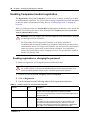
Enabling Companion handset registration . . . . . . . . . . . . . . . . . . . . . . . . . . . . . . . . . . 46
Enabling registration or changing the password . . . . . . . . . . . . . . . . . . . . . . . . . . 46
Using portable DNs to show handset status . . . . . . . . . . . . . . . . . . . . . . . . . . . . . . . . 47
Registering Companion portables . . . . . . . . . . . . . . . . . . . . . . . . . . . . . . . . . . . . . . . . 48
Registering the C3060 handset . . . . . . . . . . . . . . . . . . . . . . . . . . . . . . . . . . . . . . . 48
Confirm that the handset is registered . . . . . . . . . . . . . . . . . . . . . . . . . . . . . . . . . . 49
Registering the C3050 handset . . . . . . . . . . . . . . . . . . . . . . . . . . . . . . . . . . . . . . . 50
Confirm that the handset is registered . . . . . . . . . . . . . . . . . . . . . . . . . . . . . . . . . . 51
Registering a C3020 handset (Canada only) . . . . . . . . . . . . . . . . . . . . . . . . . . . . 52
Confirm that the handset is registered . . . . . . . . . . . . . . . . . . . . . . . . . . . . . . . . . . 52
Deregistering a handset . . . . . . . . . . . . . . . . . . . . . . . . . . . . . . . . . . . . . . . . . . . . . . . 53
Deregistering a portable from the system . . . . . . . . . . . . . . . . . . . . . . . . . . . . . . . 53
Deregistering a C3060 handset . . . . . . . . . . . . . . . . . . . . . . . . . . . . . . . . . . . . . . 54
Deregistering a C3050 handset . . . . . . . . . . . . . . . . . . . . . . . . . . . . . . . . . . . . . . 54
Deregistering a C3020 handset . . . . . . . . . . . . . . . . . . . . . . . . . . . . . . . . . . . . . . 55
Measuring RSSI for the handsets . . . . . . . . . . . . . . . . . . . . . . . . . . . . . . . . . . . . . . . . 55
Measuring undirected RSSI for C3060 handsets. .
Measuring directed RSSI for C3060 handsets. . . .
Measuring undirected RSSI for C3050 handsets. .
Measuring directed RSSI for C3050 handsets. . . .
Measuring undirected RSSI for C3020 handsets. .
Measuring directed RSSI for C3020 handsets. . . .
.......
.......
.......
.......
.......
.......
......
......
......
......
......
......
.......
.......
.......
.......
.......
.......
....
....
....
....
....
....
56
56
57
57
58
58
Companion DN record parameters . . . . . . . . . . . . . . . . . . . . . . . . . . . . . . . . . . . . . . . 59
Handset features and restrictions . . . . . . . . . . . . . . . . . . . . . . . . . . . . . . . . . . . . . . . . 60
Feature access for Companion . . . . . . . . . . . . . . . . . . . . . . . . . . . . . . . . . . . . . . . 61
Language selection . . . . . . . . . . . . . . . . . . . . . . . . . . . . . . . . . . . . . . . . . . . . . . . . 62
Index . . . . . . . . . . . . . . . . . . . . . . . . . . . . . . . . . . . . . . . . . . . . . . . . . . . . . . . . 63
P0609345 01
5
Figures
Figure 1
Process map: Installing Companion support hardware . . . . . . . . . . . . . . . . . . . 15
Figure 2
RPI unit . . . . . . . . . . . . . . . . . . . . . . . . . . . . . . . . . . . . . . . . . . . . . . . . . . . . . . . 16
Figure 3
RPI mounting holes . . . . . . . . . . . . . . . . . . . . . . . . . . . . . . . . . . . . . . . . . . . . . . 17
Figure 4
Opening the RPI cover . . . . . . . . . . . . . . . . . . . . . . . . . . . . . . . . . . . . . . . . . . . . 18
Figure 5
RPI components . . . . . . . . . . . . . . . . . . . . . . . . . . . . . . . . . . . . . . . . . . . . . . . . . 18
Figure 6
RPI connector printed-circuit board . . . . . . . . . . . . . . . . . . . . . . . . . . . . . . . . . . 20
Figure 7
Output connector pinout . . . . . . . . . . . . . . . . . . . . . . . . . . . . . . . . . . . . . . . . . . . 21
Figure 8
Input connector pinout . . . . . . . . . . . . . . . . . . . . . . . . . . . . . . . . . . . . . . . . . . . . 21
Figure 9
Bracket termination board . . . . . . . . . . . . . . . . . . . . . . . . . . . . . . . . . . . . . . . . . 27
Figure 10
Slide the cover on bracket . . . . . . . . . . . . . . . . . . . . . . . . . . . . . . . . . . . . . . . . . 28
Figure 11
Installed antenna and lightning surge protectors (USA) . . . . . . . . . . . . . . . . . . 31
Figure 12
Antenna with antenna bracket (USA) . . . . . . . . . . . . . . . . . . . . . . . . . . . . . . . . . 33
Figure 13
Lightning surge protector and bracket (USA) . . . . . . . . . . . . . . . . . . . . . . . . . . . 34
Figure 14
Indoor directional external antenna (Canada) . . . . . . . . . . . . . . . . . . . . . . . . . . 36
Figure 15
Indoor omnidirectional external antenna (Canada) . . . . . . . . . . . . . . . . . . . . . . 37
Figure 16
Install the outdoor omnidirectional external antenna (Canada) . . . . . . . . . . . . . 39
Figure 17
Install the lightning surge protector (Canada) . . . . . . . . . . . . . . . . . . . . . . . . . . 40
Figure 18
Companion headings . . . . . . . . . . . . . . . . . . . . . . . . . . . . . . . . . . . . . . . . . . . . . 41
Figure 19
Process map: Setting up Companion handsets for registration . . . . . . . . . . . . . 43
Business Communications Manager Companion Configuration Guide
6
P0609345 01
7
Tables
Table 1
RPI Requirements . . . . . . . . . . . . . . . . . . . . . . . . . . . . . . . . . . . . . . . . . . . . . . . 17
Table 2
Cable distances . . . . . . . . . . . . . . . . . . . . . . . . . . . . . . . . . . . . . . . . . . . . . . . . . 19
Table 3
Input wiring . . . . . . . . . . . . . . . . . . . . . . . . . . . . . . . . . . . . . . . . . . . . . . . . . . . . . 22
Table 4
RPI-8 BIX wiring chart . . . . . . . . . . . . . . . . . . . . . . . . . . . . . . . . . . . . . . . . . . . . 22
Table 5
RPI-16 BIX wiring chart . . . . . . . . . . . . . . . . . . . . . . . . . . . . . . . . . . . . . . . . . . . 24
Table 6
Minimum distance between office areas and base stations . . . . . . . . . . . . . . . . 26
Table 7
Clearance for the base stations . . . . . . . . . . . . . . . . . . . . . . . . . . . . . . . . . . . . . 27
Table 8
UTAM messages . . . . . . . . . . . . . . . . . . . . . . . . . . . . . . . . . . . . . . . . . . . . . . . . 29
Table 9
Radio settings . . . . . . . . . . . . . . . . . . . . . . . . . . . . . . . . . . . . . . . . . . . . . . . . . . 44
Table 10
Cell information . . . . . . . . . . . . . . . . . . . . . . . . . . . . . . . . . . . . . . . . . . . . . . . . . 45
Table 11
Handset registration and password information . . . . . . . . . . . . . . . . . . . . . . . . . 46
Table 12
Companion telephone programming . . . . . . . . . . . . . . . . . . . . . . . . . . . . . . . . . 59
Table 13
Features available to a Companion portable handset . . . . . . . . . . . . . . . . . . . . 61
Business Communications Manager Companion Configuration Guide
8
P0609345 01
9
Preface
This guide explains how to install and program Companion base stations and handsets.
Before you begin
This guide assumes the following:
•
•
•
The Business Communications Manager is installed and initialized, and all hardware appears
to be working.
That a site survey has been conducted and the installer has access to these plans.
That all configuration operators have a working knowledge of the Windows operating system
and graphical user interfaces.
Symbols used in this guide
This guide uses symbols to draw your attention to important information. The following symbols
appear in this guide:
Caution: Caution Symbol
Alerts you to conditions where you can damage the equipment.
Danger: Electrical Shock Hazard Symbol
Alerts you to conditions where you can get an electrical shock.
Warning: Warning Symbol
Alerts you to conditions where you can cause the system to fail or work improperly.
Note: Note Symbol
A Note alerts you to important information.
Tip: Tip Symbol
Alerts you to additional information that can help you perform a task.
!
Security Note: This symbol indicates a point of system security where a default should
be changed, or where the administrator needs to make a decision about the level of
security required for the system.
Business Communications Manager Companion Configuration Guide
10
Preface
Text conventions
This guide uses the following text conventions:
angle brackets (< >)
Indicates that you choose the text to enter based on the description
inside the brackets. Do not type the brackets when entering the
command.
Example: If the command syntax is: ping <ip_address>
you enter: ping 192.32.10.12
bold Courier text
Indicates command names and options and text that you need to enter.
Example: Use the dinfo command.
Example: Enter show ip {alerts|routes}.
italic text
Indicates book titles
plain Courier
text
Indicates command syntax and system output, for example, prompts
and system messages.
Example: Set Trap Monitor Filters
FEATURE
HOLD
RELEASE
Indicates that you press the button with the coordinating icon on
whichever set you are using.
How to get help
If you do not see an appropriate number in this list, go to www.Nortelnetworks.com/support.
USA and Canada
Authorized Distributors - ITAS Technical Support
Telephone: 1-800-4NORTEL (1-800-466-7835)
If you already have a PIN Code, you can enter Express Routing Code (ERC) 196#.
If you do not yet have a PIN Code, or for general questions and first line support, you can enter
ERC 338#.
Website: http://www.nortelnetworks.com/support
Presales Support (CSAN)
Telephone: 1-800-4NORTEL (1-800-466-7835)
Use Express Routing Code (ERC) 1063#
EMEA (Europe, Middle East, Africa)
P0609345 01
Preface
11
Technical Support - CTAS
Telephone:
* European Freephone
European Alternative/
United Kingdom
Africa
Israel
00800 800 89009
+44 (0)870-907-9009
+27-11-808-4000
800-945-9779
* Note: Calls are not free from all countries in Europe, Middle East or Africa
Fax: 44-191-555-7980
email: [email protected]
CALA (Caribbean & Latin America)
Technical Support - CTAS
Telephone: 1-954-858-7777
email: [email protected]
APAC (Asia Pacific)
Technical Support - CTAS
Telephone: +61-2-870-8800
Fax: +61 388664644
email: [email protected]
In-country toll free numbers
Australia 1800NORTEL (1800-667-835)
China 010-6510-7770
India 011-5154-2210
Indonesia 0018-036-1004
Japan 0120-332-533
Malaysia 1800-805-380
New Zealand 0800-449-716
Philippines 1800-1611-0063
Singapore 800-616-2004
South Korea 0079-8611-2001
Taiwan 0800-810-500
Thailand 001-800-611-3007
Service Business Centre & Pre-Sales Help Desk +61-2-8870-5511
Business Communications Manager Companion Configuration Guide
12
Preface
P0609345 01
13
Chapter 1
Installing the Companion system
This section describes the process for installing a Companion wireless system.
The following information is based on the following understandings:
•
A site survey has been completed and you have determined the exact locations of the base
stations around your site.
•
You have determined how many handsets you want.
To determine this, you need to know whether your system has a DS30 channel 2/6 or 3/5 split.
•
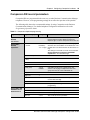
The Companion requires a DSM8 module for every 32 handsets. You can assign a maximum
of 32 Companion handsets per DSM because the Companion system can use both B channels.
You can install a maximum of two DSM8s or one DSM32 for Companion handsets, per
system, providing your system is configured with a DS30 channel 2/6 split. Refer to the
Business Communications Manager Installation and Maintenance Guide for detailed
hardware configuration.
The Companion hardware must be in place and configured before you can use the handsets to
connect to the Business Communications Manager. This section describes the installation of the
various pieces of hardware.
This section contains the following information:
•
“Companion components overview” on page 14
•
“Hardware installation process map” on page 15
•
“Companion components overview” on page 14
•
“Remote power interconnect (RPI) unit overview” on page 16
•
“Mounting the RPI unit” on page 17
•
“Wiring the base station and connecting the RPI” on page 19
•
“Companion base station installation overview” on page 25
•
“Positioning a Companion base station” on page 26
•
“Attaching a Companion base station” on page 27
•
“Installing external antennas and lightning surge protection” on page 30
Business Communications Manager Companion Configuration Guide
14 Chapter 1 Installing the Companion system
Companion components overview
Your Companion portable telephone allows you to leave your desk without missing telephone
calls. The telephones can access most Business Communications Manager business features such
as call forward, call transfer, voice conference, and voice messaging using feature codes.
Business Communications Manager Companion has four main components:
Software - Companion software manages the telephone traffic between Companion base stations
and portable telephones. Base stations connect to the Business Communications Manager in the
same way that Business Communications Manager telephones do. You register the Companion
portable telephones on the system. They do not require any ports on the system. You can connect a
maximum of 60 portable telephones and a maximum of 32 base stations (32 cells) to the system.
Note: If you choose a 3/5 channel split for your system, you cannot assign a module to channel 7.
This limits you to a maximum of 16 base stations, which can support a maximum of 30 handsets.
Companion base stations — Position the base stations around the coverage area to send and
receive calls between the portable telephones and Business Communications Manager. Base
stations use digital radio technology and support handoff and roaming within the coverage area.
The coverage area can be a maximum of 160,000 square meters (1,700,000 square feet) when
using the maximum number of base stations. The base station can use internal or external
antennas. For most installations, the internal antenna will be used. If you need to install external
antennas, refer to “Installing external antennas and lightning surge protection” on page 30.
Companion wireless handsets — Business Communications Manager supports the following
wireless handsets: Companion 3020, Companion C3050 Etiquette, Companion C3050 CT2Plus,
and Companion C3060.
The portable telephones used with your Business Communications Manager system are small,
lightweight units with complete digital performance to provide clear voice quality. Companion
portable telephones feature a three-line, 16-character, alphanumeric display.
Administration and maintenance tools — Programming of the Companion system is easily and
quickly done through the Business Communications Manager Unified Manager. You can assign
portable telephones to the system, check base station parameters, and enable and disable
registration through programming.
Companion Diagnostics software allows you to run diagnostics on the wireless system. You run
the diagnostics using a personal computer located at the customer site or in a remote location.
P0609345 01
Chapter 1 Installing the Companion system 15
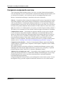
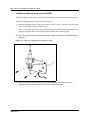
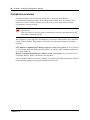
Hardware installation process map
The following figure provides an overview of the process for installing the support hardware for a
Companion wireless system.
Figure 1 Process map: Installing Companion support hardware
Business
Communications
Manager
DSM module
installed and
configured
Restore system
to operation
Configure DN
records for the
handsets
Companion
equipment
Install external
antennas and
lightning protection,
if required
Install remote power
interconnect (RPI)
Install base stations
Connect base stations to DSM
Register Companion sets*
*In the United States, you must enter
a UTAM keycode before you register
the handsets.
Note: Companion wireless availability is region-specific. This option also requires a software
keycode for activation.
Business Communications Manager Companion Configuration Guide
16 Chapter 1 Installing the Companion system
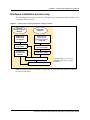
Remote power interconnect (RPI) unit overview
The remote power interconnect unit (RPI) provides remote power for base station support.
The following figure shows a diagram of the RPI.
Figure 2 RPI unit
Caution: The RPI unit must have the DC backup power supplied by a UL listed universal
power supply (UPS).
The UPS must have an output voltage rating of 44 to 52 V DC, with a maximum fault
current limit of 6 A to protect the RPI output wiring. If these requirements are not met, it is
necessary to use class 1 wiring.
Warning: You must install the RPI units inside a building.
The AC outlet powering the RPI must be installed near the equipment and must be easily
accessible.
The length of the RPI cord, from the outside surface of the unit to the plug, must be a
minimum of 1.3 m (4.5 ft) and a maximum of 4.6 m (15 ft).
There are two versions of the RPI unit:
•
The RPI-8 BIX UL supports a maximum of eight base stations.
•
The RPI-16 BIX UL supports a maximum of 16 base stations.
Each RPI has a connection printed-circuit board and either one (RPI-8 BIX UL) or two (RPI-16
BIX UL) power supply units (PSUs). The maximum input power consumption of an RPI is 240 W.
If you use a UPS 48 V dc backup source, the maximum input power requirement of the RPI is
140 W.
You can upgrade an RPI-8 BIX UL to an RPI-16 BIX UL by installing a second PSU to the RPI-8
BIX UL.
P0609345 01
Chapter 1 Installing the Companion system 17
If you distribute the RPIs around the site, the number and type of RPIs depend on where you place
them and how you power the base stations.
To determine how many base stations and how many PSUs you need for the number of base
stations, use the following table:
Table 1 RPI Requirements
Base stations
RPI-16 and RPI-8 required
PSUs required
1–8
1 RPI-8
1 PSU
9–16
1 RPI-16
2 PSUs
17–24
1 RPI-16 and 1 RPI-8
3 PSUs
25–32
2 RPI-16
4 PSUs
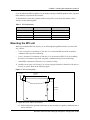
Mounting the RPI unit
When you mount the RPI unit, ensure you are following these guidelines before you start with
step 1 below:
•
Leave a clearance of a minimum of 125 mm (5 in.) around the RPI to provide acceptable
ventilation and to prevent overheating.
•
Leave a clearance of a minimum of 300 mm (12 in.) between two RPIs if you are installing
them above one another, to provide acceptable ventilation and to prevent overheating.
•
Install RPIs a minimum of 300 mm (12 in.) from the ceiling.
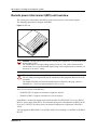
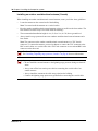
1
Partially screw in two #10 50 mm (2 in.) screws using the keyholes in the back of the unit, at
the top, as a guide. Refer to the following figure.
Figure 3 RPI mounting holes
25 mm
(1 in.)
325 mm
(13 in.)
50 mm
(2 in.)
Keyholes
300 mm
(12 in.)
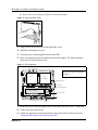
2 Open the cover with a screwdriver.
a
On the latch on the right side of the unit, use the screwdriver to push in, and then down, to
release the latch.
Business Communications Manager Companion Configuration Guide
18 Chapter 1 Installing the Companion system
b
Remove the cover by lifting it up. Refer to the following figure.
Figure 4 Opening the RPI cover
3 Hang the RPI on the two screws and tighten the screws.
4 Install the remaining two screws.
5 Feed the power cord through the bottom of the RPI.
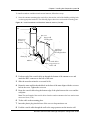
6 Route it through the clip and around the strain relief support. The following figure
shows how to route the power cord.
Figure 5 RPI components
Jumper lead to PSU 2
The RPI-8 has grounding straps and
plates fitted to allow an upgrade to
an RPI-16.
Grounding plates
PSU 1
PSU 2
(if equipped)
Grounding strap
Ferrite rings
Up to
16
inputs
(TCM)
Up to 16 outputs
(TCM + power)
Power supply cabling
Connection board
Clip
Strain relief support
Power cord
7 Route the power cord to the input power socket just to the left of PSU 1, on the left.
8 Connect the plug to the socket.
9 Follow the appropriate wiring instructions in the wiring charts in the next section,
“Wiring the base station and connecting the RPI”.
P0609345 01
Chapter 1 Installing the Companion system 19
CAUTION: Do not apply power to the RPI until its installation and wiring are complete.
10 After the cable is wired correctly, connect the RPI power cord to the ac outlet.
11 Label each RPI.
Wiring the base station and connecting the RPI
The maximum two-way DC loop resistance for power pairs, including interconnections for each
base station, is 75 ohms. You need one or two power pairs between the RPI and the base station.
The number of power pairs depends on the wire size of the power pair and the distance between
the base station and the RPI.
This section contains this information:
•
“Connecting the RPI” on page 20
•
“RPI output connections” on page 21
•
“RPI input connections” on page 21
•
“RPI-8 BIX wiring chart” on page 22
•
“RPI-8 BIX wiring chart” on page 24
Caution: Do not run unprotected power cables outdoors.
The maximum cable distances allowed between the RPI and the base station depend on the size of
wire you use. Refer to the following table.
Table 2 Cable distances
Wire size
Single pair
Double pair
0.6 mm (22 AWG)
800 m (2,500 ft.)
1200 m (4,000 ft.)
0.5 mm (24 AWG)
500 m (1,500 ft.)
1000 m (3,000 ft.)
Caution: When you use two power pairs, connect both pairs with the same polarity.
Business Communications Manager Companion Configuration Guide
20 Chapter 1 Installing the Companion system
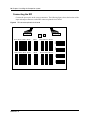
Connecting the RPI
Connect the power pairs to the correct connectors. The following figure shows the location of the
input and output connectors on the RPI connector printed-circuit board.
Figure 6 RPI connector printed-circuit board
0B1X1 0B1X2 0B1X3 0B1X4
0B1X9
0B1X10 0B1X11 0B1X12
0B1X5 0B1X6
OBIX5
OBIX6 0B1X7
OBIX7 0B1X8
OBIX8
0B1X9
OBIX13
0B1X13 OBIX15
0B1X14OBIX16
0B1X15
OBIX14
OBIX9
OBIX10 OBIX11 OBIX12
IBIX4
IBIX4
IBIX3
IBIX2
IBIX2
IBIX3
IBIX2
IBIX1
OBIX1 OBIX2 OBIX3 OBIX4
P0609345 01
Chapter 1 Installing the Companion system 21
RPI output connections
Feed the output pairs in through the bottom of the RPI and route the pairs to the output connectors.
The following figure shows how to route the output pairs. If you use one pair to power a base
station, connect the power pair to -PWR(1) and +PWR(1). If you use two pairs to power a base
station, connect one pair to -PWR(1) and +PWR(1), and the second pair to -PWR(2) and
+PWR(2).
Caution: Ensure both pairs have the same polarity.
If you connect two power pairs with opposite polarities, you can damage the base station
and RPI.
Figure 7 Output connector pinout
OBIXn
OBIXn
-PWR(1)
-PWR(1)
-PWR(2)
TCM
TCM
TCM
TCM
+PWR(2)
+PWR(2)
+PWR(1)
+PWR(1)
RPI input connections
Feed the TCM input pairs from the Business Communications Manager distribution frame through
the top of the RPI and route them to the input connectors (IBIX1 to IBIX4).
The following figure shows how to route the input pairs. The maximum number of input pairs in
an RPI installation is 16.
Figure 8 Input connector pinout
Pin 11
Pin
IBIXn
IBIXn
Pin77 Pin
Pin55 Pin
Pin 33
Pin
Pin
Pin 88 Pin
Pin 66
Pin
Pin 44
Pin
Pin 22
Business Communications Manager Companion Configuration Guide
22 Chapter 1 Installing the Companion system
The table below lists the pinout and signal references.
Table 3 Input wiring
Connector
Pin
IBIX1
1, 2
TCM 1
OBIX1
3, 4
TCM 2
OBIX2
5, 6
TCM 3
OBIX3
IBIX2
IBIX3
IBIX4
Signal
Output connector
7, 8
TCM 4
OBIX4
1, 2
TCM 5
OBIX5
3, 4
TCM 6
OBIX6
5, 6
TCM 7
OBIX7
7, 8
TCM 8
OBIX8
1, 2
TCM 9
OBIX9
3, 4
TCM 10
OBIX10
5, 6
TCM 11
OBIX11
7, 8
TCM 12
OBIX12
1, 2
TCM 13
OBIX13
3, 4
TCM 14
OBIX14
5, 6
TCM 15
OBIX15
7, 8
TCM 16
OBIX16
RPI-8 BIX wiring chart
The following table lists the wiring chart for the RPI-8 BIX.
Table 4 RPI-8 BIX wiring chart
Pin
RPI Connector printed-circuit board
26
1
27
OBIX1
BS1
Label
Wire color
-PWR
White-Blue
Blue-White
TCM
2
Orange-White
28
+PWR
3
30
-PWR
OBIX2
BS2
6
P0609345 01
White-Brown
Brown-White
TCM
5
31
White-Green
Green-White
29
4
White-Orange
White-Slate
Slate-White
+PWR
Red-Blue
Blue-Red
Chapter 1 Installing the Companion system 23
Table 4 RPI-8 BIX wiring chart (Continued)
Pin
RPI Connector printed-circuit board
32
7
33
OBIX3
BS3
Label
Wire color
-PWR
Red-Orange
Orange-Red
TCM
8
Green-Red
34
+PWR
9
36
-PWR
OBIX4
BS4
TCM
+PWR
12
-PWR
OBIX5
BS5
TCM
+PWR
15
-PWR
OBIX6
BS6
TCM
+PWR
18
-PWR
OBIX7
BS7
Yellow-Brown
Brown-Yellow
TCM
20
Yellow-Slate
Slate-Yellow
46
+PWR
21
Violet-Blue
Blue-Violet
47
-PWR
OBIX8
BS8
Violet-Orange
Orange-Violet
TCM
23
24
Yellow-Green
Green-Yellow
44
49
Yellow-Orange
Orange-Yellow
43
48
Yellow-Blue
Blue-Yellow
17
22
Black-Slate
Slate-Black
41
45
Black-Brown
Brown-Black
40
19
Black-Green
Green-Black
14
42
Black-Orange
Orange-Black
38
16
Black-Blue
Blue-Black
37
39
Red-Slate
Slate-Red
11
13
Red-Brown
Brown-Red
35
10
Red-Green
Violet-Green
Green-Violet
+PWR
Violet-Brown
Brown-Violet
Business Communications Manager Companion Configuration Guide
24 Chapter 1 Installing the Companion system
RPI-8 BIX wiring chart
The following table lists the wiring chart for the RPI-16 BIX.
Table 5 RPI-16 BIX wiring chart
Pin
RPI Connector printed-circuit board
26
1
27
OBIX9
BS9
Label
Wire color
-PWR
White-Blue
Blue-White
TCM
2
Orange-White
28
+PWR
3
4
-PWR
OBIX10
BS10
+PWR
6
-PWR
OBIX11
BS11
+PWR
9
-PWR
OBIX12
BS12
+PWR
12
Black-Orange
Orange-Black
38
-PWR
OBIX13
BS13
Black-Green
Green-Black
TCM
14
P0609345 01
Black-Blue
Blue-Black
37
15
Red-Slate
Slate-Red
TCM
11
40
Red-Brown
Brown-Red
35
39
Red-Green
Green-Red
34
13
Red-Orange
Orange-Red
TCM
8
36
Red-Blue
Blue-Red
32
10
White-Slate
Slate-White
31
7
White-Brown
Brown-White
TCM
5
33
White-Green
Green-White
29
30
White-Orange
Black-Brown
Brown-Black
+PWR
Black-Slate
Slate-Black
Chapter 1 Installing the Companion system 25
Table 5 RPI-16 BIX wiring chart (Continued)
Pin
RPI Connector printed-circuit board
41
16
42
OBIX14
BS14
Label
Wire color
-PWR
Yellow-Blue
Blue-Yellow
TCM
17
Orange-Yellow
43
+PWR
18
45
-PWR
OBIX15
BS15
TCM
Yellow-Slate
Slate-Yellow
46
+PWR
21
Violet-Blue
Blue-Violet
47
48
Yellow-Brown
Brown-Yellow
20
22
Yellow-Green
Green-Yellow
44
19
Yellow-Orange
-PWR
OBIX16
BS16
Violet-Orange
Orange-Violet
TCM
23
Violet-Green
Green-Violet
49
+PWR
24
Violet-Brown
Brown-Violet
Companion base station installation overview
Before you install portable equipment, ensure that a site planner determines base station locations
and records the base station information in a provisioning record.
This section includes the detailed information about:
•
“Positioning a Companion base station” on page 26
•
“Attaching a Companion base station” on page 27
•
“Installing the base station” on page 27
Caution: You must install all base stations within 1230 m (4000 ft., TCM wiring length)
of the BCM1000 or base station module.
To optimize seamless hand off, the difference in TCM wiring length between neighboring
base stations must not exceed 300 m (1,000 ft.).
Before you install or move wireless equipment in the United States, check that you have approval
from UTAM Inc.
The United States FCC has appointed UTAM Inc. as the body responsible for coordinating and
verifying the installation or relocation of unlicensed, personal wireless communication devices. To
Business Communications Manager Companion Configuration Guide
26 Chapter 1 Installing the Companion system
comply with UTAM Inc., the system uses keys and credits to control user capacity and to ensure
system location verification. You require these software keys and credits to activate Companion
services. You purchase these credits at the time you place the order.
Positioning a Companion base station
Avoid installing base stations on large concrete or marble columns because these columns affect
radio coverage. If possible, place the base station a minimum of 1 m (40 in.) from these types of
columns. Do not install a base station with the antenna housings near metal objects. Be careful not
to damage existing wiring or panels.
Do not position base stations in ducts, plenums, or hollow spaces used to transport environmental
air except where the duct, plenum or hollow space is created by a suspended ceiling having lay-in
panels. When you need more than one base station in a cell to meet traffic requirements, position
the base stations at the same cell center.
To place all base stations in the same cell center:
•
for the USA, a minimum of 54 in. and a maximum of 9 ft. 9 in. distance between the center of
one base station to the center of another
•
for Canada, a minimum of 9 cm and a maximum of 1.5 m distance from edge to edge
Warning: Never install base stations in rows.
Position base stations away from office areas or areas with high portable telephone traffic. The
table below shows the minimum distance between office areas and base stations. Install the base
station on the ceiling or high on walls to maintain these minimum distances.
Table 6 Minimum distance between office areas and base stations
Number of base stations in the cell Minimum distance between office areas and base stations
1
1 m (40 in.)
2
1.4 m (56 in.)
3
1.8 m (72 in.)
4
2 m (80 in.)
P0609345 01
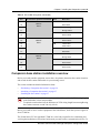
Chapter 1 Installing the Companion system 27
Attaching a Companion base station
Install base stations on a wall or on a ceiling. When installing base stations on a wall, install them
with their covers at the bottom, as shown in the figure below. Allow for clearances around the base
station as indicated in the following table.
Table 7 Clearance for the base stations
Clearance conditions
Canada
USA
Clearance from all other objects
9 cm
3.5 in.
Vertical clearance from base station center to base station center
27 cm
54 in.
Horizontal clearance from base station center to base station center
41 cm
54 in.
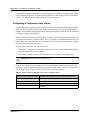
Installing the base station
1
Fasten the bracket into position using two #8 38-mm (1-1/2 in.) screws.
2 Route the cable from the BCM1000 through the top or bottom opening.
3 Wind any excess cable around the posts, then fasten the cable under the strain relief.
4 Connect the wires to the BIX connector on the bracket termination board as shown in
the following figure.
Figure 9 Bracket termination board
TCM
TCM
-PWR(1)
-PWR(1)
-PWR(2)
-PWR(2)
TCM
TCM
+PWR(1)
+PWR(1)
+PWR(2)
+PWR(2)
RJ11
RJ11jack
jack
The polarity of the TCM connections is not important. If you connect the two power pairs to
the bracket terminal board of the base station, you must connect the power pairs with the same
polarity.
CAUTION: Ensure that the RPI is off before connecting power pairs to the base station.
5 Install the base station on the bracket. Snap it into position.
6 Connect the power RJ-11 jumper lead to the RJ-11 jacks on the termination board and
the base station.
Business Communications Manager Companion Configuration Guide
28 Chapter 1 Installing the Companion system
7 For plug top power supplies only, connect the power supply connector to the base
station power connector. Make sure the base station uses a class 2 plug top power
source only.
CAUTION: If you insert the power supply connector in the wrong direction, you can damage
the plug top power supply and the base stations.
Position the power supply connector in the correct direction and push it into place.
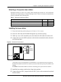
8 In the space provided on the label attached to the lower right corner of the mounting
bracket, record the port number used.
Include the marking information for all of the base stations on the completed installation floor
plans.
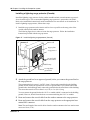
9 Slide the cover on the bracket, using the guide to position it correctly. Refer to the
following figure.
10 Snap it into place.
Figure 10 Slide the cover on bracket
P0609345 01
Chapter 1 Installing the Companion system 29
Registering Companion telephones
To use Companion portable telephones, you must first install radio base stations to transmit and
receive radio signals to and from the portable telephones. See “Companion base station installation
overview” on page 25.
You use a different method to install portable telephones than desktop telephones. There are no
direct connections between the portable telephones and the system.
Do the following:
•
Install the batteries and battery charging units for each portable, using the instructions that
come with the portable.
•
Enter the software keys for Companion in the Business Communications Manager Unified
Manager under Software keys
•
Register every Companion portable for use with the system.
Note: You must register a portable telephone before you can use it. By default, Companion
portable telephones are not assigned extension numbers. The range of portable extensions
available for wireless registration is 565 to 596. For more information about registering and
programming Companion portables, refer to “Configuring Companion handsets” on page 41.
Restarting the system after a software update
If you added a base station that requires a software update, the system begins downloading the
software to the base station. The display shows BS-1 Dload Start.
1
Press CLEAR to clear the message. When the base station software finishes downloading, the
BS-1 Dload Done appears.
2 Press CLEAR to clear the message. Some base stations do not power up at the same
time, and this message repeats at the beginning of each download.
In the United States, after restarting, the display shows one of the messages listed in the following
table:
Table 8 UTAM messages
If display shows
See
UTAM code req’d
System logical identifier (LID) information
UTAM test failed
See alarm codes in the Windows NT event log.
Warning: A loss of unlicensed transition and management for microwave (UTAM)
information occurs when upgrading US Business Communications Manager systems.
You need UTAM Recovery Codes.
Business Communications Manager Companion Configuration Guide
30 Chapter 1 Installing the Companion system
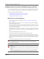
Installing external antennas and lightning surge protection
You can use external antennas to provide a broad range for your Companion system. Ensure that
any external installations comply with local regulations and include lightning surge protection.
This section contains the following procedures:
•
“Installing antennas (United States of America)” on page 31
•
“Installing a lightning surge protector (USA)” on page 34
•
“Installing antennas (Canada)” on page 35
Read before you install equipment
•
You must install the antenna vertically. Refer to “Before you install an outdoor antenna
(USA)” on page 31.
•
Use #8, 12 mm to 50 mm (1/2 in. to 2 in.) screws to install the antenna bracket and lightning
surge protector bracket to the wall.
•
Always ensure that the antenna is clear of any adjacent obstruction or metal objects. If you use
more than one external antenna at a cell center, separate the antennas at by least 1 m (40 in.) to
avoid radio interference problems.
•
When running the coaxial cable inside or outside, be careful not to damage the cable. Damage
to the cable affects its performance. The minimum recommended bending radius is 200 mm
(8 in.).
•
The coaxial cable length must not exceed 10 m (33 ft).
•
Use RG-58AU coaxial cables to connect the antennas to the base stations.
•
You can attach a proprietary extension cable between the lightning surge protector and the
antenna or between the lightning surge protector and the base station. Make sure you keep the
total cable length as short as possible and use only the recommended extension cable when
necessary.
•
You must install a lightning surge protector for each external antenna.
Warning: FCC requirements.
In the United States, the FCC requires that you connect only approved antennas to
Companion base stations.
Caution: Do not install the outdoor antenna or the lightning surge protector during an
electrical storm.
Always turn off the base station power before connecting the coaxial cable of an outdoor
antenna.
Always install the lightning surge protector at the cable entry point into the building.
Connect the lightning surge protector to ground before you connect the coaxial cable.
P0609345 01
Chapter 1 Installing the Companion system 31
Installing antennas (United States of America)
The following points cover special information about installations in the United States of America.
•
The outdoor antenna connectors on the base station are special proprietary BNC connectors.
Refer to “Before you install an outdoor antenna (USA)” on page 31 and “Installing an outdoor
antenna (USA)” on page 32.
•
Antennas are supplied with cables attached and terminated with special proprietary BNC plugs
to join with the connector on the base station. Refer to “Installing an indoor directional
antenna” on page 36.
•
Cables are not supplied with outdoor antennas.
•
You must also install lighting surge protection on outside antenna installations. Refer to
“Installing a lightning surge protector (USA)” on page 34.
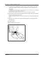
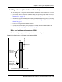
Before you install an outdoor antenna (USA)
The following figure diagrams all the required hardware for installing outdoor antennas.
Figure 11 Installed antenna and lightning surge protectors (USA)
Antenna
Wall
Wall
Antenna
Mounting
Mounting bracket
bracket
Back to
back
Back
to back
proprietary
proprietary
BNC
BNC connectors
connectors
Lightning surge
Lightning surge arrestor
arrestor
withbracket
with mounting
mounting bracket
to base station or proprietary extension cable
to Base Station or proprietary extension cable
Business Communications Manager Companion Configuration Guide
32 Chapter 1 Installing the Companion system
Before you install an outdoor antenna, check the following points:
•
Locate the antenna on the external wall of the building.
•
Keep the outdoor antenna as close as possible to the base station connected to it. The base
station must always be inside the building. The recommended installation height for the
antenna is 13 to 16 ft. above ground.
•
Always install a lightning surge protector between an outdoor antenna and a base station.
Refer to the following figure.
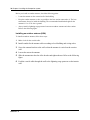
Installing an outdoor antenna (USA)
To install an outdoor antenna, follow these steps:
1
Make a hole for the coaxial cable.
2 Install conduit for the antenna cable according to local building and wiring codes.
3 Screw the antenna bracket to the wall so that the antenna is vertical on the exterior
wall.
4 Loosen the nut on the antenna.
5 Slide the antenna into the slot of the bracket and tighten the nut. Refer to the following
figure.
6 Feed the coaxial cable through the wall to the lightning surge protector on the interior
wall.
P0609345 01
Chapter 1 Installing the Companion system 33
Figure 12 Antenna with antenna bracket (USA)
Wiring information
•
The recommended wire gauge is 6 AWG.
•
Connect the ground lead to the building ground. Do not connect to a ground rod or series of
ground rods.
•
If you cannot connect the ground lead to the building ground, connect the ground lead to the
metal frame of the building. The connection must be no more than six to 10 ft.
•
You can connect the ground lead to the 120 V ac conduit, which is connected to the building
ground. However, using the ac conduit is not the preferred method of installation.
•
The connector between the antenna and the lightning surge protector and between the
lightning surge protector and the base station is a proprietary BNC connector. You must align
the BNC connectors before you can make the connection.
Business Communications Manager Companion Configuration Guide
34 Chapter 1 Installing the Companion system
Installing a lightning surge protector (USA)
Install the lightning surge protector to protect the Companion components from electrical surges.
To install a lightning surge protector, follow these steps:
1
Install the lightning surge protector on the interior wall as close as possible to the entry point
of the coaxial cable from the outdoor antenna.
Before you connect the ground lead to the lightning surge protector, attach the ground lead to
an approved ground. Refer to the Wiring information tips box on the next page.
2 Route and connect the coaxial cable from the outdoor antenna to the lightning surge
protector.
Figure 13 Lightning surge protector and bracket (USA)
3 Route and connect the coaxial cable from the lightning surge protector to the
appropriate base station connector. Refer to the following figure.
P0609345 01
Chapter 1 Installing the Companion system 35
Installing antennas (Canada)
There are three types of external antennas available in Canada:
•
indoor directional antenna (“Installing an indoor directional antenna” on page 36)
•
indoor omnidirectional antenna (“Installing an indoor omnidirectional antenna (Canada)” on
page 37)
•
outdoor omnidirectional antenna (“Installing an outdoor omnidirectional antenna (Canada)”
on page 38).
Each type of installation requires a specific installation technique. As well, you must install a
lightning surge protector for every outdoor antenna installed (“Installing a lightning surge
protector (Canada)” on page 40).
Outdoor requirements
Before you install the antenna, ensure that your plan meets the following requirements:
•
If you are installing an outdoor antenna on a metal surface greater than 18 cm (7 in.) in
diameter, position the antenna perpendicular to the surface.
•
When running the coaxial cable inside or outside, be careful not to damage the cable, which
affects its performance. The minimum recommended bending radius is 20 mm (0.8 in.).
•
Always ensure that the antenna is clear of any adjacent obstruction or metal objects. If you use
more than one outdoor antenna at a cell center, separate the antennas at by least 0.5 m (20 in.)
to avoid radio interference problems.
•
Use RG-58/U coaxial cables to connect the antennas to the base stations.
CAUTION: Use only passive antennas to connect to the Companion base stations.
The coaxial cable you use to connect the external antenna to a Companion base station must have
an impedance of 50 ohms.
Business Communications Manager Companion Configuration Guide
36 Chapter 1 Installing the Companion system
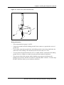
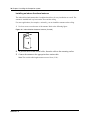
Installing an indoor directional antenna
The indoor directional antenna has a backplate that allows for easy installation on a wall. The
antenna is installed half way between the floor and the ceiling.
For some applications (for example, a stairwell), you can install the antenna on the ceiling.
1
Use four screws at each corner of the antenna. Refer to the following figure.
Figure 14 Indoor directional external antenna (Canada)
2 To prevent stress on the coaxial cable, fasten the cable to the mounting surface.
3 Connect the antenna to the appropriate base station radio.
Note: The coaxial cable length must not exceed 10 m (33 ft.).
P0609345 01
Chapter 1 Installing the Companion system 37
Installing an indoor omnidirectional antenna (Canada)
To install an indoor omnidirectional antenna, use the following guidelines:
•
Use the bracket supplied to install the antenna on a wall or ceiling. This bracket provides the
necessary clearance between the floor or wall and the antenna.
•
Mount the bracket so that the external antenna is vertical. The recommended installation
position on a wall is halfway between the floor and the ceiling.
1
Insert the antenna in the bracket so that the antenna is vertical.
2 Use two screws to install the bracket to the wall or ceiling.
3 To prevent cable stress on the coaxial cable, fasten the cable to the mounting surface
with a clamp.
4 Connect the external antenna to the appropriate base station.
Note: The length of the coaxial cable must not exceed 10 m (33 ft.).
The following figure shows the two methods of installing the indoor omnidirectional external
antenna.
Figure 15 Indoor omnidirectional external antenna (Canada)
mm
3030mm
Co-axial
Co-axial
cable
cable
Cable
Cable
clamp
clamp
Ceiling mount
installation
Ceiling mount installation
Wall mount
installation
Wall mount installation
30
mm
30 mm
Co-axial
Co-axial cable
cable
Cable
Cable clamp
clamp
Business Communications Manager Companion Configuration Guide
38 Chapter 1 Installing the Companion system
Installing an outdoor omnidirectional antenna (Canada)
When installing an outdoor omnidirectional external antenna, ensure you follow these guidelines:
•
Locate the antenna on the external wall of the building.
Note: You must install the antenna on a vertical surface.
•
Keep the outdoor omnidirectional external antenna as close as possible to the base station. The
base station itself must always be located inside the building.
•
The recommended installation height is 4 m (13 ft) to 5 m (16.5 ft) above ground level.
•
Always install a surge protector between an outdoor omnidirectional external antenna and a
base station.
Note: The connector on the outdoor omnidirectional external antenna is a TNC female
connector. To connect the antenna, you need an adapter to connect the TNC connector to the
BNC coaxial cables or a coaxial cable with a TNC male connector on one end and BNC male
connector on the other end.
Caution: Fit lightning protection to the antenna if appropriate.
See “Installing a lightning surge protector (Canada)” on page 40 for more information.
Important points to remember:
• Do not install the external antenna or the lightning surge protector during an electrical
storm.
• Always turn off the base station power before connecting the coaxial cable of an
outdoor antenna.
• Always install the antenna at the cable entry point into the building.
• Connect the lightning surge protector to ground before connecting the coaxial cable.
P0609345 01
Chapter 1 Installing the Companion system 39
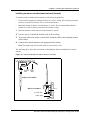
To install an outdoor omnidirectional external antenna, follow these steps:
1
Screw the antenna mounting plate vertically to the exterior wall of the building with lag bolts
or other appropriate hardware. The following figure shows how to fasten the mounting plate.
Figure 16 Install the outdoor omnidirectional external antenna (Canada)
Mast
Mast
Set screw
screw
Set
Exterior wall
Exterior
mounting
plate wall
Connector at
Connector
of
at the
the base
base of
mast
thethe
mast
mounting plate
Shroud
Shroud
Lag bolts (or
appropriate
Lag
bolts or other
mounting hardware
appropriate
mounting
hardware
Plastic
Plasticplug
plug
Cable
Cableties
ties
Co-axial cable to
Co-axial
cable toon
surge protector
surge
protector
interior
wall on
interior wall
2 Feed one end of the coaxial cable up through the bottom of the antenna cover and
attach the BNC connector to the base of the mast.
3 Slide the mast down into the cover until it fits.
4 Rotate the mast until the threaded hole in the base of the mast aligns with the set screw
hole in the cover. Tighten the set screw.
5 Route the coaxial cable along the bottom edge of the plate between the cover and the
wall plate.
Note: The total length of the coaxial cables from the outdoor antenna to the base station must
not exceed 10 m (33 ft.).
6 Tie the cable to the mounting plate.
7 Insert the plastic plug into the base of the cover to keep moisture out.
8 Feed the coaxial cable through the wall to the surge protector on the interior wall.
Business Communications Manager Companion Configuration Guide
40 Chapter 1 Installing the Companion system
Installing a lightning surge protector (Canada)
Install the lightning surge protector for the outdoor omnidirectional external antenna to protect it
from electrical surges. The recommended lightning surge protector is part number A0382082.
Refer to the installation instructions from the manufacturer for more details on its installation. To
install a lightning surge protector, follow these steps:
1
Install the surge protector on the interior wall as close as possible to the entry point of the
coaxial cable from the outdoor antenna.
The following figure shows where to locate the surge protector. Follow the installation
instructions provided with the surge protector.
Figure 17 Install the lightning surge protector (Canada)
Exterior
Exterior
wall
Wall
Interiorwall
Interior
Wall
Copper
Copperplates
plates
Surge protector
protector
Surge
Co-axialcable
cableto
Co-axial
to base
station
Base
Station
Co-axialcable
cableto
Co-axial
to
outdoor
outdoor external
external antenna
antenna
Cable clamps
Cable clamps
Low impedance
impedance
Low
groundlead
lead
ground
2 Attach the ground lead to an approved ground, before you connect the ground lead to
the surge protector.
The recommended wire gauge is 6 AWG (4 mm). Connect the ground lead to the building
ground. Do not connect to a ground rod or series of ground rods. If you cannot connect the
ground lead to the building ground, connect the ground lead to the metal frame of the building.
The connection must be no more than 2 m (6.5 ft.) to 3 m (10 ft.) long.
You can connect the ground lead to the 120 V ac conduit (which is connected to the building
ground). However, Nortel Networks does not recommend using the 120 V ac conduit.
3 Route and connect the coaxial cable from the outdoor antenna to the surge protector.
4 Route and connect the coaxial cable from the surge protector to the appropriate base
station BNC connector.
Note: The total length of the coaxial cables from the outdoor antenna to the base station must
not exceed 10 m (33 ft.).
P0609345 01
41
Chapter 2
Configuring Companion handsets
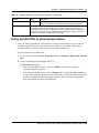
The Companion heading in the Unified Manager allows you to assign Companion portable
telephones to the system, check base station parameters, and enable and disable registration
through programming.
This section includes information about:
•
•
•
•
•
•
•
•
•
•
“Companion overview” on page 42
“Process map: Companion portable handset” on page 43
“Defining radio data” on page 44
“Enabling Companion handset registration” on page 46
“Using portable DNs to show handset status” on page 47
“Registering Companion portables” on page 48
“Deregistering a handset” on page 53
“Measuring RSSI for the handsets” on page 55
“Companion DN record parameters” on page 59
“Handset features and restrictions” on page 60
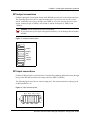
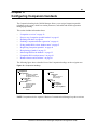
The following figure shows a detailed view of the Companion headings on the navigation tree.
Figure 18 Companion headings
Companion
Registration
Registration enabled
Credits available
Registration password
Portable DNs
DN xxx
DN status
Radio Data
Credits available
Total credits
System LID
Re-evaluation
Status
Radios
Radio xxxx
Radio
Cell assignment
Antenna type
Cells
Cell 01
Cell Radios
Cell neighbors
Cell radio neighbors
NOTE: Companion wireless requires a Business Communications Manager keycode to activate.
Business Communications Manager Companion Configuration Guide
42
Chapter 2 Configuring Companion handsets
Companion overview
Companion handsets interact with base stations that are hardwired to the Business
Communications Manager through a DTM (digital trunk module) media bay module. These
handsets provide you with the mobility to move about your office and continue or initiate
conversations as you move about.
Caution: Companion Wireless systems have specific deployment areas and licensing
requirements.
They also require a site survey prior to deployment to ensure proper distribution of the
base stations around the call site.
The Companion system supports C3050 Etiquette, Companion C3060 Portable, and Companion
C3050 CT2Plus handsets. Each handset comes with a user manual that describes the handset
operation.
Note: Business Communications Manager software version 2.5 or greater: If your system has
a 3/5 DS30 split and Partial Double Density (PDD), you can only add 32 Companion handsets to
your system on Bus 06.
Business Communications Manager software version 3.0 or greater: If your system is set to
Full Double Density (FDD), Companion is not supported.
Once the handsets and base stations are installed, you configure the handsets through the Business
Communications Manager using special Companion DN records.
P0609345 01
Chapter 2 Configuring Companion handsets
43
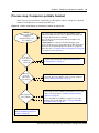
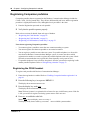
Process map: Companion portable handset
Refer to the process map below, which leads you through the order for setting up Companion
handsets on the Business Communications Manager.
Figure 19 Process map: Setting up Companion handsets for registration
BCM is installed and
configured.
Companion DN records
are configured.
Are the
base stations
installed and
connected?
Have you
set up the
radios in the
base stations?
Has registration
been enabled?
Your system must be set to partial double density (PDD). Install a
DSM16 on DS30 Bus 06 and/or 07, or a DSM32 on DS30 Bus 06,
proving both Bus 06 and 07 are available.
Refer to the Business Communications Manager Installation and
Maintenance Guide.
Companion DNs are configured in the Unified Manager under
Services, Telephony Services, System DNs, Inactive DNs, Companion
DNs. Refer to the Programming Operations Guide for configuration
details. Refer also to “Companion DN record parameters” on page 59
for Companion specific information.
Companion base stations must be mapped and installed to
cover the expected usage area. Refer to “Companion DN
record parameters” on page 59.
Perform a reevaluation to register the base station radios to
the system. Then ensure that the cells are correctly configured.
Refer to “Defining radio data” on page 44.
Enable registration and change the registration password, if
required. This opens the channels for the handsets to connect and
register to the system. Refer to “Enabling Companion handset
registration” on page 46.
To view which DNs are available for registration, refer to DN
headings under Portable DNs. Refer to “Using portable DNs to
show handset status” on page 47
Register each handset.
Refer to “Registering Companion
portables” on page 48.
Business Communications Manager Companion Configuration Guide
44
Chapter 2 Configuring Companion handsets
Defining radio data
The Radio data heading allows you to view the number of credits available, the total number of
credits and the System LID.
This section contains the following information:
•
•
•
“Using Reevaluation to assign cells to base stations” on page 44
“Programming base station radios” on page 44
“Defining base station cells” on page 45
Using Reevaluation to assign cells to base stations
Radio re-evaluation automatically assigns the proper cell configuration to each radio in a base
station. When you add or remove base stations, you must apply Reevaluation to the system.
Follow these steps to apply reevaluation to your Companion system.
1
From Companion, click the Radio data heading.
The Radio data window appears.
2 Beside System SLID, enter the radio ID.
On the navigation menu, click on Re-evaluation.
If the Re-evaluation status reads Required, you can carry out the re-evaluation.
3 On the Configuration menu click Re-eval now or Schedule.
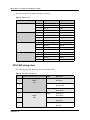
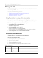
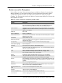
Programming base station radios
The Radios setting allows you to program base station radio settings.
Follow these steps to define the settings.
1
From Companion, click the key beside Radio data.
2 Click the key beside Radios.
3 Choose a radio number from the list.
4 Use the information in the following table to configure the radio.
Table 9 Radio settings
Attribute
Value
Radio
Read-only identification This is the number that identifies the radio base station.
number
Cell assign
Unassigned
Assigned
P0609345 01
Description
This box indicates if the cell has been activated.
Chapter 2 Configuring Companion handsets
45
Table 9 Radio settings (Continued)
Attribute
Value
Description
Antenna type
Internal
External
This is the type of antenna the radio base station is connected to.
A cell is the area covered by one or more radios in close proximity. As you move around your
office while on a call with your portable, the call hands off from one cell to another. A call on a
portable hands off from one cell to another only if Business Communications Manager assigns
those cells as neighbors. Business Communications Manager automatically assigns cell neighbors
and re-evaluates the cell-to-cell configuration when you add or remove base stations.
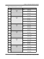
Defining base station cells
Cell programming allows you to examine settings for the cell radio, cell neighbor, and cell radio
neighbor.
Follow these steps to set up cells for your Companion system.
1
Click on the keys beside Services, Telephony services, Companion, Radio data, Cells.
2 Select a cell number (Cell 01 to Cell 32).
3 Use the information in the following table to check cell information.
Table 10 Cell information
Attribute
Value
Description
Cell Radios
<five-digit number>
View the five-digit number of any radios assigned to this cell. For
example, if radio 07012 is in the cell, 07012 assigned appears.
Cell neighbors
<two-digit cell number>
View the two-digit number of any cells that border a particular cell in
a system.
Click the cell number to see the settings: Assigned or Unassigned.
For example, cell 01, Neighbour:03 and Neighbour:04 display. This
means that cells 03 and 04 are assigned as cell neighbors.
Cell radio neighbors <two-digit cell number>
View the two-digit number of any cells that border a particular cell in
a system (the cell neighbors) plus any cells that border the cell
neighbors.
Click the cell number to see the settings: Assigned or Unassigned.
For example, cell 01, Radio neighbour:03, Radio neighbour:04
display, and Radio neighbour:11. Cell 11 does not appear as a cell
neighbor, therefore, it must be a neighbor of cell 03 or 04. Refer to
the example under Cell neighbor.
Business Communications Manager Companion Configuration Guide
46
Chapter 2 Configuring Companion handsets
Enabling Companion handset registration
The Registration heading under Companion, provides access to controls to enable you to allow
or disallow handset registration. You can also enter or change a registration password, that further
protects the system from unauthorized entry. Refer to “Enabling registration or changing the
password”.
When you enable registration, the Portable DNs heading displays the DNs that can be used for the
handsets. These DNs are the same as those found under the Telephony services, System DNs,
Active Companion DNs heading.
Warning: Before you install or move wireless equipment in the United States, check that
you have approval from UTAM Inc.
The United States FCC has appointed UTAM Inc. as the body responsible for
coordinating and verifying the installation or relocation of unlicensed, personal wireless
communication devices. To comply with UTAM Inc., the system uses keys and credits to
control user capacity and to ensure system location verification. You require these
software keys and credits to activate Companion services. You purchase these credits at
the time you place the order.
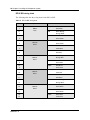
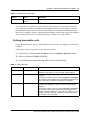
Enabling registration or changing the password
To enable user registration or to change the password, follow these steps:
Warning: Registration should normally be disabled.
For security reasons, and to prevent unauthorized users from being registered to your
system, disable Registration when you have finished registering the portables.
1
Click the keys beside Services, Telephony Services, Companion.
2 Click on Registration.
3 Use the information in the following table to check registration information.
Table 11 Handset registration and password information
Attribute
Value
Description
Registration
Y, N
You must enable registration for the entire Business Communications
Manager system to allow registration of individual portables.
After you have registered the sets, come back and disable registration by
setting this field to N.
Credits available
Read-only.
This field shows the number of credits that are available for handset
registration.
This number must be any positive number to allow portables to be
registered. The number decrements by one with each successful
registration. The number increments when a telephone is deregistered.
More credits can be added by purchasing additional keycodes.
P0609345 01
Chapter 2 Configuring Companion handsets
47
Table 11 Handset registration and password information (Continued)
Attribute
Value
Description
Registration password
<five digits>
Enter the digital code that needs to be identified on the handset to allow
access to the system. This number can be changed, as required.
Tips: You can choose any combination of one to six digits for the password. It is easier
to remember the password if the digits spell a word. Provide this password only to
selected personnel, to prevent unauthorized access to programming. The implications of
such access can include the rearrangement of line assignments, which can affect the
operation of the Business Communications Manager.
Using portable DNs to show handset status
After you enable registration for your Business Communications Manager system, a series of
extension numbers (565 to 596) are automatically available for registration. Check that an
extension number is available before registering a portable telephone to it.
To view registered and available DNs:
1
Click on the keys beside Services, Telephony Services, Companion, Registration, Portable
DNs.
2 Click a portable DN (for example, DN 471).
The DN status box appears.
• If the extension number shows a status of Available, it is ready for registering a
Companion portable telephone.
• If the extension number shows a status of Registered, a Companion portable telephone is
already registered to that extension number. In this case, you can pick a different extension
number, or deregister the current portable telephone. You must perform deregistration
both at the portable and from Unified Manager.
Business Communications Manager Companion Configuration Guide
48
Chapter 2 Configuring Companion handsets
Registering Companion portables
Companion portables that are supported on the Business Communications Manager include the
C3060, C3050, C3020 (Canada only). They all have different dial pad icons, and the registration
procedure is slightly different for each, although the basic procedure is the same:
1
Enter the Registration password on each portable.
2 Verify that the portable operates properly.
Refer to these sections for details about each type of handset:
•
•
•
“Registering the C3060 handset” on page 48
“Registering the C3050 handset” on page 50
“Registering a C3020 handset (Canada only)” on page 52
Notes about registering Companion portables:
•
•
•
•
You cannot register a portable to more than one extension number per system.
You cannot register more than one portable to one extension number.
You can register a portable to more than one system. If a portable telephone is to be used in
more than one Business Communications Manager system, its owner must know which
registration slot number was used to register the portable telephone with each system. Nortel
Networks recommends that users register their most frequently used system in slot 1.
If a portable telephone is lost or broken, deregister it from the system before replacing it with
another portable telephone. Refer to “Deregistering a handset” on page 53.
Registering the C3060 handset
To register each portable with Business Communications Manager:
1
Ensure that registration is enabled. Refer to “Enabling Companion handset registration” on
page 46.
2 Press the following keys, in sequence: MENU***.
The display shows ADMINISTRATION.
3 Press the display key under SYS.
The display shows WIRELESS SYSTEMS.
Note: Wireless Systems is a registration list of names for up to six different systems. If the list
is full, you need to de-register an existing system name to add a new one.
4 Press ADD to establish a radio link.
Note: If ADD does not display, start over at step 1.
The display briefly shows Adding SYSTEM: <next available system number>.
P0609345 01
Chapter 2 Configuring Companion handsets
•
•
49
If the display shows No connection, the radio link was not established.
Note: If more than 30 minutes has elapsed since the last handset registration, you may
need to re-enable the system for registration. Return to step 1.
If a radio link is established, the display shows Pswd:.
5 Enter the registration password.
The display shows WTN:
Note: If you enter the wrong password, the display shows Invld Pswd.
6 Enter the DN record number you want to assign to this handset.
The display shows Enter name.
• If the display shows Invld WTN, then you entered an invalid DN.
• If the display shows Reg failed, the handset failed to register to the system.
• If you try to register a handset to the same system more than one, the display shows the
registered name (Registered as <name>).
7 Using the dialpad, enter a maximum of 16 characters for the system name.
•
•
•
•
More than one letter is represented by most dialpad keys. Press the key the number of
times it takes to display the letter you want.
Press SPACE to add a blank space to the name.
Press BKSP to delete the previous character.
Press the right arrow button if the next letter is on the same button.
8 Press SAVE.
The display shows the registered name.
9 Turn off registration for your system.
Confirm that the handset is registered
Make this simple test to confirm that the handset registered to the system.
1
From the WIRELESS SYSTEMS list, ensure the system you just entered is displayed.
2 Power off the handset.
3 Power on the handset.
•
•
If the handset displays the correct system name proceed with the next step.
If an incorrect system name displays, return to the WIRELESS SYSTEMS list and use the
up and down arrow keys to find the correct system name.
4 Make a call.
•
•
If you hear dial tone and the display shows LINK, dial the number of a working telephone.
If the target telephone rings, registration is confirmed.
If you do not hear dial tone, check that you have selected the correct system or re-register
the handset.
Business Communications Manager Companion Configuration Guide
50
Chapter 2 Configuring Companion handsets
5 Receive a call.
Note: If the portable has the same DN as a desk telephone, ensure that the desk telephones is
idle and Call Forward is deactivated. Ensure that the ringer on the handset is turned on.
• On another telephone in the system, dial the telephone of the registered portable. If the
portable rings, registration is confirmed.
• If the portable does not ring or you do not hear dial tone on the portable, refer to the
Companion handset user guide for troubleshooting tips or contact system technical
support.
Registering the C3050 handset
1
Ensure that registration is enabled. Refer to “Enabling Companion handset registration” on
page 46.
2 Open the handset flap.
The portable displays the current system name or No system selected for two seconds.
3 Press the key labeled System.
The display shows WIRELESS SYSTEMS.
Note: This handset can be registered for a maximum of nine systems.
4 Press ADD to establish a radio link.
Note: If ADD does not display, start over at step 1.
The display briefly shows Adding SYSTEM:#<next available system number>.
•
If the display shows No connection, the radio link was not established.
Note: If more than 30 minutes has elapsed since the last handset registration, you may
need to re-enable the system for registration. Close the flap and return to step 2.
•
If a radio link is established, the display shows Pswd:.
5 Enter the registration password.
The display shows DN:
Note: If you enter the wrong password, the display shows Invld Pswd. In this case, close
the flap and repeat from step 2.
6 Enter the DN record number you want to assign to this handset.
The display shows Enter name.
• If the display shows Invld DN, then you entered an invalid DN.
• If the display shows Reg failed, the handset failed to register to the system.
• If you try to register a handset to the same system more than one, the display shows the
registered name (Registered as <name>).
P0609345 01
Chapter 2 Configuring Companion handsets
51
7 Using the dialpad, enter a maximum of 16 characters for the system name.
•
•
•
•
More than one letter is represented by most dialpad keys. Press the key the number of
times it takes to display the letter you want.
Press SPACE to add a blank space to the name.
Press BKSP to delete the previous character.
Press the right and left arrow buttons to move forward and back.
8 Press SAVE.
The display shows the registered name.
9 Turn off registration for your system.
Confirm that the handset is registered
Make this simple test to confirm that the handset registered to the system.
1
Close, then open the portable flap.
•
•
If the handset displays the correct system name proceed with the next step.
If an incorrect system name displays, return to the WIRELESS SYSTEMS list and use the
up and down arrow keys to find the correct system name.
2 Make a call.
•
•
If you hear dial tone and the display shows LINK, dial the number of a working telephone.
If the target telephone rings, registration is confirmed.
If you do not hear dial tone, check that you have selected the correct system or re-register
the handset.
3 Receive a call.
Note: If the portable has the same DN as a desk telephone, ensure that the desk telephones is
idle and Call Forward is deactivated. Close the handset flap and ensure that the ringer on the
handset is turned on.
• On another telephone in the system, dial the telephone of the registered portable. If the
portable rings, registration is confirmed.
• If the portable does not ring or you do not hear dial tone on the portable, refer to the
Companion handset user guide for troubleshooting tips or contact system technical
support.
Business Communications Manager Companion Configuration Guide
52
Chapter 2 Configuring Companion handsets
Registering a C3020 handset (Canada only)
The following section describes the procedures involved in registering Companion C3020 portable
telephones.
1
Ensure that registration is enabled. Refer to “Enabling Companion handset registration” on
page 46.
2 Press Shift and then press Memory.
3 Press Office.
4 Check the portable display.
•
•
If the portable has space for another system, the display shows Office n:Free.
If the display does not show Office n:Free, follow the procedures in to overwrite the
system number. Then return to this procedure and perform the following step.
5 Press Shift and then press Memory.
The display shows Registering ..., then Pswd:
6 Enter the Registration password.
7 When the display clears and displays DN:, enter the DN for the handset.
The display clears and shows Reg’n complete.
8 Turn off registration for your system.
Confirm that the handset is registered
Make this simple test to confirm that the handset registered to the system.
1
Make a call.
•
•
If you hear dial tone, dial the number of a working telephone. If the target telephone rings,
registration is confirmed.
If you do not hear dial tone, check that you have selected the correct system or re-register
the handset.
2 Receive a call.
Note: If the portable has the same DN as a desk telephone, ensure that the desk telephones is
idle and Call Forward is deactivated. Ensure that the handset flap is closed and the ringer on
the handset is turned on.
• On another telephone in the system, dial the telephone of the registered portable. If the
portable rings, registration is confirmed.
•
P0609345 01
If the portable does not ring or you do not hear dial tone on the portable, refer to the
Companion handset user guide for troubleshooting tips or contact system technical
support.
Chapter 2 Configuring Companion handsets
53
When you distribute the portables, tell the users that the portables are registered and give them the
corresponding extension numbers.
Deregistering a handset
Deregister an extension number from Unified Manager when:
•
•
You must replace the portable due to loss or breakage.
You want to assign the handset to a user with a different telephone number.
This section contains the following information:
•
•
•
•
“Deregistering a portable from the system” on page 53
“Deregistering a C3060 handset” on page 54
“Deregistering a C3050 handset” on page 54
“Deregistering a C3020 handset” on page 55
Deregistering a portable from the system
This procedure only clears the portable registration on the system. You must also deregister from
the portable telephone (“on-the-air” deregistration). For information about deregistering your
portable telephone, refer to the next section and the Companion Portable Telephone User Guide.
1
Click the keys beside Services, Telephony services, Companion, Registration,
Portable DNs.
2 Click a portable DN (for example, DN 471).
The DN status window appears.
3 On the Configuration menu, click Deregister.
Note: This procedure does not clear the registration data in the portable. You must also
deregister from the portable telephone (“on-the-air” deregistration).
For information about deregistering your portable telephone, refer to your Companion
Portable Telephone User Guide.
Business Communications Manager Companion Configuration Guide
54
Chapter 2 Configuring Companion handsets
Deregistering a C3060 handset
This procedure only clears the registration information on the portable. You must also
deregister the portable from the system. Refer to “Deregistering a portable from the system”
on page 53.
1
Press the following keys, in sequence: MENU***.
The display shows ADMINISTRATION.
2 Press the display key under SYS.
The display shows WIRELESS SYSTEMS.
Note: Find the system name on the list using the up and down arrow keys.
3 Press ERASE.
The display shows Erase item?
4 Press OK.
The display shows Deregistering ..., and then Item erased.
Deregistering a C3050 handset
This procedure only clears the registration information on the portable. You must also
deregister the portable from the system. Refer to “Deregistering a portable from the system”
on page 53.
1
Open the flap of the handset.
2 Press the key labeled System.
The display shows WIRELESS Systems.
3 Using the up and down arrow keys, find the system name on the list using the up and
down arrow keys.
4 Press ERASE.
The display shows Erase item?
5 Press OK.
The display shows Deregistering ..., and then Item erased.
P0609345 01
Chapter 2 Configuring Companion handsets
55
Deregistering a C3020 handset
This procedure only clears the registration information on the portable. You must also deregister
the portable from the system. Refer to “Deregistering a portable from the system” on page 53.
1
Press Shift, and then Memory.
2 Press Office.
The display shows Office n:.
3 Press either Shift and then #, or Shift and then * until you display the system you want
to deregister.
4 Press Shift, and then 0.
The display shows Deregister?
5 Press Shift and then 0 again.
The display shows Deregistering ... and then Deregistered.
6 To continue using the portable, press Release.
Measuring RSSI for the handsets
The Receive Signal Strength Indicator (RSSI) is a measurement of the signal strength the Base
Station receives from the portable. The Base Station controls the power transmitting mode of the
portable.
•
Measuring undirected RSSI for handsets:
When the Base Station receives a weak signal, it instructs the portable to transmit in
high-power. When the Base Station receives a strong signal, it instructs the portable to
transmit in low-power.
— C2060: Strongest RSSI value = -35 dBm. Weakest RSSI value = approximately -94 to
-100 dBm. (“Measuring undirected RSSI for C3060 handsets” on page 56)
— C2050: Strongest RSSI value = -45 dBm (USA)/-44 dBm (Canada). Weakest RSSI
value = approximately -94 to -100 dBm. (“Measuring undirected RSSI for
C3050 handsets” on page 57
— C2030: Strongest RSSI value = -44 dBm. Weakest RSSI value = approximately -85 to
-95 dBm. (“Measuring undirected RSSI for C3020 handsets” on page 58)
Note: The Receive Signal Strength indicator overrides normal display. Therefore, you cannot
receive calls while measuring RSSI.
•
Measuring directed RSSI for handsets:
You may want to measure the RSSI between a portable and a specific Base Station radio. For
example, you may suspect that one of the two radios in a Base Station is not working properly.
You can also use directed RSSI to prevent hand-off while you find a cell edge. To measure the
RSSI of a specific radio, you must be in range of two Base Stations—the one you want to
measure and another Base Station.
Business Communications Manager Companion Configuration Guide
56
Chapter 2 Configuring Companion handsets
Note: You cannot measure the directed RSSI of both radios in the Base Station at the same
time.
Before you measure directed RSSI, note the following:
— The five-digit ID of the Base Station radio you want to measure, by mapping the Base
Station location to the TCM port. The first four digits indicate the TCM port to which
the Base Station is connected. The last digit indicates the number of the radio on the
Base Station. For example, the number 03142 on the Base Station is connected to
TCM port 0314, and 2 is the radio number. The five-digit number might be printed on
a label attached to the Base Station mounting bracket.
— The radio IDs of all other Base Stations in the same location.
Measuring undirected RSSI for C3060 handsets
1
Press the Menu button.
The display shows MENU.
2 Press the up and down arrow keys until the display shows Feature request.
3 Press SELCT.
The display shows A-.
4 Press * 8 9 8.
The display shows the cell number, the radio ID of the Base Station to which the portable is
linked, the power mode (high or low), followed by the signal strength and the channel. For
example, 8 15112 H 67 29.
Hand-off occurs normally between the cells.
Note: In this example, the cell is 8, the card is 15, the port is 11, the radio is 2, and the channel
is 29. The signal strength measured by the Base Station is -67 dBm, and the H indicates the
portable is transmitting in high-power mode (an L indicates low-power mode)
5 Power off the handset to end the connection.
Measuring directed RSSI for C3060 handsets
1
Follow steps 1 to 5 of “Measuring undirected RSSI for C3060 handsets”.
•
•
If the display shows the ID of a Base Station neighboring the one you want to measure,
proceed to the next step.
If the display shows the ID of the Base Station you want to measure, move out of the cell
boundary range so that handoff occurs and then continue with the next step.
2 Press the Menu key.
The display shows MENU.
3 Press the up and down arrow keys until the display shows Feature request.
P0609345 01
Chapter 2 Configuring Companion handsets
57
4 Press SELCT.
The display shows A-.
5 Press * 8 9 9.
6 Enter the five-digit ID code for the Base Station radio you want to measure. The
display shows the cell number, the radio ID of the Base Station to which the portable is
linked, the power mode (high or low), followed by the signal strength and the channel.
For example, 8 15112 H 67 29.
Hand-off does not occur as you move between the cell boundaries. The link drops when you
move out of range.
Note: In this example, the cell is 8, the card is 15, the port is 11, the radio is 2, and the channel
is 29. The signal strength measured by the Base Station is -67 dBm, and the H indicates the
portable is transmitting in high-power mode (an L indicates low-power mode).
7 To end the connection, press the Menu button.
Measuring undirected RSSI for C3050 handsets
1
Open the flap on the handset.
2 Press the Line key.
3 Press * 8 9 8.
The portable displays the radio ID of the Base Station to which the portable is linked, followed
by the signal strength and the power mode, for example 03142 - 54 H.
Hand-off occurs normally between the cell boundaries.
In this example, the module is 03, the port is 14, and the radio is 2. The signal strength
measured by the Base Station is -54 dBm, and the H indicates that the portable is transmitting
in high-power mode (an L indicates low-power mode).
4 Close the connection. Press End or close the flap.
Measuring directed RSSI for C3050 handsets
1
Follow steps 1 to 3 in the section “Measuring undirected RSSI for C3050 handsets”.
2 When the portable displays the Base Station ID you want to measure, move out of the
cell boundary range so that hand-off occurs, and then press End.
3 Press Line.
4 Press *899.
5 Enter the five-digit ID code for the Base Station radio you want to measure.
The portable displays this ID followed by the signal strength and the power mode, for example
03142 - 54 H. Hand-off does not occur as you move between the cell boundaries. The link
drops when you move out of range.
Business Communications Manager Companion Configuration Guide
58
Chapter 2 Configuring Companion handsets
In this example, the module is 03, the port is 14, and the radio is 2. The signal strength
measured by the Base Station is -54 dBm, and the H indicates the portable is transmitting in
high-power mode (an L indicates low-power mode).
6 Press End or close the flap to disconnect.
Measuring undirected RSSI for C3020 handsets
1
Press Line. Wait for dial tone.
2 Press * 8 9 8.
The display shows the radio ID of the Base Station to which the portable is linked, followed by
the signal strength, for example 03121 - 67.
In this example, the module is 03, the port is 12, and the radio is 1. The signal strength is
-67dBm.
Hand-off occurs normally.
3 Press Release or close the flap to end the connection.
Measuring directed RSSI for C3020 handsets
1
Follow steps 1 to 3 in the section “Measuring undirected RSSI for C3020 handsets”.
2 Press *899.
3 Enter the five-digit ID code for the Base Station radio you want to measure.
The display shows this ID followed by the signal strength, for example 03121 - 67. If you
have not established a connection with the desired Base Station radio, you hear a tone when
you hold the portable to your ear.
The system drops the link when you move out of range of your Base Station (no
hand-off).
4 Press Release or close the flap to disconnect.
P0609345 01
Chapter 2 Configuring Companion handsets
59
Companion DN record parameters
Companion DNs are programmed in the same way as other Business Communications Manager
telephones. However, some programming settings do not affect the operation of the portable.
The following table shows the recommended settings for using Companion on the Business
Communications Manager. For detailed telephone configuration information refer to the
Programming Operations Guide.
Table 12 Companion telephone programming
Programming level
Programming option
Setting
Notes
System DNs...,
DN XXX,
Line access
Answer DNs
<set DN>
This is the number of the stationary telephone that is
twinned with the handset. When the stationary
telephone gets a call, the Companion mirrors the call.
System DNs...,
DN XXX,
Capabilities
Forward
no answer
Fwd to: <DN> This stops the Companion portable from ringing
when the call is forwarded to its new destination. The
Fwd Delay:
<no. of rings> portable user can still answer the call, but it does not
ring.
The settings for Forward no answer are found under
System DNs/Active Companion DNs/DN##/
Capabilities in the Unified Manager.
Forward on busy
Y
Do not disturb
on busy
N
Handsfree
N
Handsfree answerback None
System DNs.../DN
XXX/Restrictions/
Set Restrictions
Pickup group
<group
number>
A portable can be part of a pickup group and
answers calls ringing at telephones in the same
group when the user enters FEATURE 76.
Paging
Y
Page zone
1
Direct dial
Set 1
Hotline
None
Priority call
Y
Requires special configuration of hardware and
programming
Set lock
Y
Does not apply to portables.
Allow last number
Y
Does not apply to portables.
Allow saved number
Y
Does not apply to portables.
Allow link
Y or N
This can be set to N for portables.
A portable cannot be a Direct dial telephone. It can
use the Direct dial digit.
Business Communications Manager Companion Configuration Guide
60
Chapter 2 Configuring Companion handsets
Handset features and restrictions
Your Companion cordless telephone system uses multiple base stations to provide full coverage
around your office.
As you move from one part of your office to another, your call passes from one base station to the
next.
•
•
•
In rare instances, during a Message session, softkey display prompts on your portable may
disappear. This is a normal condition and is improved by staying within range of a base
station.
While you are moving within range, you may hear a slight clipping during a call. Clipping
occurs as a call is handed off from one base station to the next.
Problems with lost connections are rare, but if you notice an increase in occurrences, your base
stations may need to be moved or reprogrammed. Contact your installer to change the base
station configuration. (In the U.S. you need to obtain UTAM Inc. approval before making
changes to the base station configuration for Companion systems.) For more information, refer
to Business Communications Manager Programming Operations Guide.
Note: If you try to send a message from a desk telephone to a portable telephone, the display
of the desk telephone shows Can’t send msg.
If there is a decrease in voice quality while you are moving with a portable telephone, you may be
moving out of range from a system base station. There are three possible reasons for this:
•
•
•
The base station that covers the area you are moving into is busy or unable to pick up your
call.
Large pieces of furniture or movable partitions block the signal between you and the base
station.
You have moved out of the range covered by your system. To reconnect, retrace your steps
until you are back in range.
P0609345 01
Chapter 2 Configuring Companion handsets
61
Feature access for Companion
It is possible to use many of the same system features available to a Business Communications
Manager telephone on your cordless telephone. For more information about features and the
special codes required to use them, refer to the feature card that came with your portable
telephone. The following table describes the Business Communications Manager call features that
the Companion can access.
Table 13 Features available to a Companion portable handset
Feature
Description
Call Forward
Send calls to another telephone in your system. The display does not indicate
that calls are being forwarded. Hunt Group calls override all Call Forward
features. A Hunt Group extension can be a Call Forward destination.
Call Information
The display shows the name or extension of an internal caller. If your system is
equipped to receive CLASS information (Caller ID), the external call information
appears on the display.
Call Park
Park a call.
Call Park Retrieval
Retrieve a parked call.
Cancel Call Forward
Cancel the Call Forward feature, where calls are automatically sent to another
telephone in the system.
Conference
Create a three-way call.
Directed Call Pickup
Answer any telephone that is ringing in the system. This feature must be
enabled in the system.
Group Pickup
Answer a call ringing on another set within the same pickup group.
Host system signaling
Use link and pause.
Line Pool
Use line pools the same way a desk telephone does.
Mute
Prevent other callers from hearing you. Also, you can mute incoming calls from
ringing on a portable telephone.
Page
Page an individual telephone, several telephones, external speakers, or the
entire system. A Hunt Group extension cannot be in a page zone.
Note: Portable handsets cannot receive pages.
Pause
Program an external autodial sequence to insert a 1.5 second delay.
Prime line
This may be either an Intercom Line, an Assigned Line or a Line Pool.
Handsets without line buttons cannot have a Prime Line assigned.
Privacy
In programming, change the privacy setting for an external line assigned to the
portable. This does not give the ability to change the privacy setting on a call by
call basis.
Release
End a call or programming session.
Speed Dial
System speed dial codes only. No personal speed dial codes. The portable
directory can store up to 50 telephone numbers.
Switching between two
calls
Put one call on hold and speak to another caller.
Transfer
Transfer a call to another telephone.
Transfer using directory
Transfer a call using your portable telephone directory.
Trunk Answer
Answer a ringing call for lines placed in a Service Mode.
Business Communications Manager Companion Configuration Guide
62
Chapter 2 Configuring Companion handsets
Table 13 Features available to a Companion portable handset (Continued)
Feature
Description
Wireless Portable
Language Selection
Change the language of the prompts that appear on the portable telephone
display. Refer to “Language selection”.
Wireless Call Forward No
Answer
Forward a call without ringing. The portable user can answer a call but it does
not ring.
Language selection
The system supports a primary default language and up to three alternate languages, depending on
the system profile.
Press **501
Language - Primary
Press **502
Language - Alternate
Press **503
Language - Alternate 2
Press **504
Language - Alternate 3
P0609345 01
63
Index
A
turn off power 30
U.S. installation 31
updating software 29
wiring length, power 19
wiring RPI 19
administration/maintenance tools 14
antenna
Canada, installation 35
certification 30
Co-axial cable, maximum length 37
directional, installation 36
external 31, 38
external installation 30
indoor 37
indoor directional external antenna, installation 36
indoor installation 36
indoor omni-directional external antenna, installation
37
installation restrictions 35
installation strategy 32
Lightning surge protector 40
lightning surge protector 35
maximum length cable 40
omni-directional 37, 38
outdoor omni-directional external antenna,
installation 38
passive 35
positioning 35
proprietary extension cable 30
RG-58A U coaxial cables 30
U.S. installation 31
antenna type, Companion 44
B
backup power, RPI 16
base station 14
clearances 27
connecting plug-top power supply 28
distances 25
hand-off 25
indoor antenna 36
installation 25
maximum cable 19
minimum distances 26
omnidirectional outdoor antenna 38
positioning 14, 26
powering up 29
proprietary extension cable 30
RG-58/U coaxial cable 35
RG-58A U antenna cable 30
TCM connections 27
termination board 27
BNC connector 31, 33, 40
bracket terminal board 27
BS-1 download 29
C
cables
maximum distance 19
call
switching between 61
Call Forward
cancel, Companion 61
Companion 61
no answer, Companion 62
Call information
Companion 61
Call Park
Companion 61
retrieval, Companion 61
cell
assignment, Companion 44
neighbors, Companion programming 45
radio neighbor, Companion 45
radios, Companion 45
channel split
Companion 14
channel split limitations 14
clearances, Companion base station 27
clipping 60
coaxial cable 30, 35, 40
Companion
antenna type 44
C3050 Etiquette 14
C3050, CT2Plus 14
C3060 14
cell assignment 44
cell neighbors 45
cell radio neighbor 45
cell radios 45
disabling registration 46
double density 42
enable handset registration 46
Business Communications Manager Companion Configuration Guide
64
Index
enabling registration 46
external antenna 38
handset credits 46
handset models 42
handset status 47
licensing 42
lightning surge arrestor 34
radio ID 44
recommended settings 59
register handset 46
registration password 47
UTAM approval 46
Companion 3020 14
Companion Base Station, see base station
Companion software 14
components
RPI 18
conference
Companion 61
copyright 2
cordless telephones
Companion 60
DECT 60
features 61
coverage area, maximum 14
credits, Companion handset 46
D
DECT
cordless handsets 60
handset models 42
licensing 42
diagnostic software 14
Directed Pickup
Companion 61
directional antenna 36
disable
handset registration 46
E
enable
handset registration 46
extensions
portable telephones 29
external antenna 31
external antennas 38
F
FCC
certification, antennas 30
FDD
Companion 42
feature
cordless telephones 61
wireless Call Forward No Answer 62
wireless Portable Language Selection 62
Federal Communications Commission, see FCC
G
Group Pickup
Companion 61
H
hand-off, Companion base station 25
handsets
registering 46
status, Companion 47
host system signaling
Companion 61
Hunt groups
Companion 61
I
illustration 40
indoor antenna 36, 37
input wiring 22
install
base station 27
Companion 13
lightning surge protector 40
L
language
Companion 62
licensing
Companion and DECT 42
lightning protector, installation 30
lightning surge arrestor 31
installation 31
installation in Canada 40
installation in U.S. 34
lightning surge protector 35
limitations
P0609345 01
Index
65
antenna 35
Companion base station 26
channel split 14
Line pool
using, Companion 61
power
Companion RPI
lost calls, troubleshooting 60
power supply
RPI 16
M
minimum distances, Companion base station 26
mute
Companion 61
powering up base station 29
prime line
Companion 61
Privacy
Companion 61
N
process map
configuring lines 43
NetVision
handsets 42
programming the Companion 14
proprietary extension cable 30
O
PSU, RPI requirements 17
obstructing antennas 35
omnidirectional antenna 37, 38
R
out of range 60
radio ID 44
outdoor antennas 30
range 60
re-evaluation, see Companion programming 44
P
register handset 29
page
Companion 61
registration, Companion 46, 48
regulatory information 2
passive antenna 35
release
using, Companion 61
password
Companion 47
Remote Power Interconnect, see RPI
Pause
Companion 61
restrictions
antenna installation 35
PDD
Companion 42
RG-58/U coaxial cable 35
plug-top power supply on base station 28
RJ11 jacks 27
polarity, TCM connections 27
portable handsets 42
Business Communications Manger features 61
Companion components 44
Companion password 47
using 60
voice quality 60
Portable Language Selection 62
portable telephone
Companion 14
Companion installation 29
DN range 29
extension numbers 29
registration 29
positioning
RG-58A U coaxial cables 30
RPI
backup power requirements 16
cabling distance 19
clearance 17
components 18
connecting 20
input connectors 21
input wiring 22
installation 16
maximum cable 19
mounting 17
opening 18
output connectors 21
overheating 17
power supply 16
requirements 17
Business Communications Manager Companion Configuration Guide
66
Index
RPI-16 BIX UL 16
RPI-16 BIX wiring chart 24
RPI-8 BIX UL 16
RPI-8 BIX wiring chart 22
turn off before connecting 27
ventilation 17
wiring 19
input connections 21
output connections 21
wiring charts 22
S
softkey display prompts, troubleshooting 60
speed dial
Companion 61
surge arrestor, Companion (U.S.) 34
surge protector 35
proprietary extension cable 30
warning 30
wire gauge 33
surge protectors 30
switching between calls
Companion 61
T
T7406 42
TCM connections, base station 27
telephones
adding wireless units 13
trademarks 2
transfer
Companion 61
troubleshooting
decrease in voice quality 60
lost calls 60
softkey display prompts 60
trunk answer
Companion 61
U
uninterruptible power supply (see UPS)
UPS, RPI 16
UTAM approval 25
UTAM messages 29
UTAM, Companion keyword 46
P0609345 01
V
voice quality 60
W
wire color 22
wire gauge, surge protector 33
wireless
adding to system 13
base station installation 25
registering handsets, Companion 29
wiring
RPI 19